JP3645829B2 - Image forming method and image forming program - Google Patents
Image forming method and image forming program Download PDFInfo
- Publication number
- JP3645829B2 JP3645829B2 JP2001143209A JP2001143209A JP3645829B2 JP 3645829 B2 JP3645829 B2 JP 3645829B2 JP 2001143209 A JP2001143209 A JP 2001143209A JP 2001143209 A JP2001143209 A JP 2001143209A JP 3645829 B2 JP3645829 B2 JP 3645829B2
- Authority
- JP
- Japan
- Prior art keywords
- frame
- replacement
- transparent
- area
- transmissive
- Prior art date
- Legal status (The legal status is an assumption and is not a legal conclusion. Google has not performed a legal analysis and makes no representation as to the accuracy of the status listed.)
- Expired - Fee Related
Links
Images


Classifications
-
- G—PHYSICS
- G06—COMPUTING; CALCULATING OR COUNTING
- G06T—IMAGE DATA PROCESSING OR GENERATION, IN GENERAL
- G06T11/00—2D [Two Dimensional] image generation
- G06T11/60—Editing figures and text; Combining figures or text
Landscapes
- Physics & Mathematics (AREA)
- General Physics & Mathematics (AREA)
- Engineering & Computer Science (AREA)
- Theoretical Computer Science (AREA)
- Processing Or Creating Images (AREA)
- Image Generation (AREA)
- Controls And Circuits For Display Device (AREA)
- Display Devices Of Pinball Game Machines (AREA)
- Control Of Indicators Other Than Cathode Ray Tubes (AREA)
Description
【0001】
【発明の属する技術分野】
本発明は、オブジェクトを透かして背景を表示させる画像を形成するための画像の表示方法に関する。
【0002】
【従来の技術】
ゲーム画面に表示されるオブジェクトを透かして背景を表示させる技術として、アルファブレンディング法や加算合成等の方法が知られている。コンピュータの処理能力の向上により、個人用のゲーム機の分野においてもこうした画像処理の機能を搭載した機種が増えている。しかしながら、その機能の詳細はゲーム機に要求される能力に応じて種々異なっている。一般に、据え置き型のゲーム機では、高品質の画像を形成するための高度の画像処理機能が競って搭載される一方、携帯型のゲーム機では画像処理の負担の軽減等を目的として画像処理機能を制限する場合がある。そのような制限の一例として、複数の半透明オブジェクトが重なった場合、中間のオブジェクトを無視し、一番手前に描画されるべき半透明オブジェクトのみを一番後の背景画像に合成して描くようにしたゲーム機も存在する。
【0003】
【発明が解決しようとする課題】
ところが、上記のように一番前の半透明オブジェクトのみを背景画像と合成した場合、中間のオブジェクトの描画が省略されて不自然な画像が形成されることがある。例えば、一番手前に半透明の煙がオブジェクトとして表示されるシーンでは、その煙のみが背景画像に合成されるので、煙と背景画像との間に存在するキャラクタ等の描画が省略されてキャラクタがゲーム画面から消滅することがある。
【0004】
一方、画像の合成を行うことなくオブジェクトを透けて見えるようにする方法として、手前に重ねられるべきオブジェクトに透過領域と非透過領域とを1〜数画像ずつ交互に格子を形成するように設定し、透過領域を介して背景画像を観察できるようにした処理も知られている。しかし、この方法では、透過領域や非透過領域の大きさによっては、オブジェクトの透明領域と非透明領域との見え方の相違が目立って画像にざらつき感が生じる欠点がある。
【0005】
そこで、本発明は、背景との合成を行うことなくオブジェクトを半透明状に表示させることができ、しかも、画像の品質を高めることが可能な画像の形成方法及びそれに使用するプログラムを提供することを目的とする。
【0006】
【課題を解決するための手段】
以下、本発明について説明する。なお、本発明の理解を容易にするために添付図面の参照符号を括弧書きにて付記するが、それにより本発明が図示の形態に限定されるものではない。
【0007】
本発明の画像の形成方法は、透過領域(4)と非透過領域(5)とが少なくとも一方向に交互に設けられたオブジェクト(3)を、前記透過領域と前記非透過領域とを少なくとも部分的に交替させながら複数フレームに亘って所定の背景(2)の手前に重ねて描画する画像の形成方法であって、一のフレームとその後の他のフレームとの間における前記オブジェクトの位置の変化を検出し、その変化に基づいて前記透過領域と非透過領域との交替を制御することことにより、上述した課題を解決するものである。
【0008】
この発明によれば、オブジェクトの背景が透過領域を介して観察される一方で、オブジェクトそれ自体が非透過領域によって表現されるので、オブジェクトを半透明状に表示することができる。透過領域と非透過領域とを複数のフレーム間で交替させるので、各領域を固定した場合と比較して透過領域と非透過領域との見え方の相違が目立たないようになる。つまり、透過領域と非透過領域とをそれぞれ固定したときは、手前のオブジェクトもその背景もそれぞれ常に同じ部分が見えるため、ユーザーがその見え方の相違に気付きやすくなり、それが画像のざらつき感として感じ取られる。しかし、本発明の方法によれば、フレーム間で透過領域と非透過領域とを交替させることにより、オブジェクト及びその背景の見えている部分が複数フレーム間で動的に変化することとなる。その結果、ユーザーが透過領域と非透過領域との見え方の相違に気付きにくくなり、ざらつき感が解消される。特に、液晶モニタのように反応速度(表示内容が切り替わる速度)が比較的遅い表示装置にオブジェクト等を表示する場合には、透過領域と非透過領域の交替の周期を短くすることにより、ユーザーが透過領域と非透過領域の区別を全く感じないようになり、手前に配置されたオブジェクトがその全面に亘って半透明状に透けているような印象を受けるようになる。
【0009】
本発明の画像の形成方法は、ゲーム画面のようにオブジェクトが画面内を移動するような場合にも、画面上でオブジェクトが静止している場合にも適用できる。但し、オブジェクトの位置が変化する場合、透過領域及び非透過領域が移動して背景の見える部分が変わることがあり、そのような場合に透過領域と非透過領域とを交替させると却って背景の見える部分の変化が無くなって本発明の効果が相殺されることがある。従って、特にオブジェクトが移動する場合には、一のフレームとその後の他のフレームとの間における前記オブジェクトの位置の変化を検出し、その変化に基づいて前記透過領域と非透過領域との交替を制御することが望ましい。
【0010】
前記交替を制御する処理では、前記一のフレームにおいて前記透過領域と一致した画面上の領域が前記他のフレームにて前記交替がないと仮定した場合に前記透過領域と再度一致する否かを判断し、一致する場合には前記他のフレームにおいて前記交替を実行し、一致しない場合には前記他のフレームにおいて前記交替を実行しないようにしてもよい。この場合には、一のフレームにおいて透過領域と一致していた画面上の領域が他のフレームにおいて非透過領域と一致し、一のフレームにおいて非透過領域と一致していた画面上の領域が他のフレームにおいて透過領域と一致するようになるから、本発明の効果を最大限に発揮させることができる。
【0011】
また、特に前記透過領域と前記非透過領域とが一画素ずつ縦横に交互に設けられている場合には、前記交替を制御する処理において、画面上における前記オブジェクトの位置を示す縦方向及び横方向における座標値を二進数で加算した値を前記一のフレームと前記他のフレームとでそれぞれ算出し、それぞれの加算値における最下位桁が変化していない場合には前記他のフレームにおいて前記交替を実行し、変化している場合には前記他のフレームにおいて前記交替を実行しないようにしてもよい。このような処理を行えば、一のフレームにおいて透過領域と一致した画面上の領域が他のフレームにて前記交替がないと仮定した場合に透過領域と再度一致する否かを簡単に判断できる。
【0012】
なお、前記一のフレームと他のフレームとは連続したフレームであることが望ましい。これによりフレーム毎に透過領域と非透過領域とを交替させるか否かが判断されるので、両領域の交替周期を可能な限り短くして、高度な半透明処理が施された画像と同等の品質の画像を形成できるようになる。
【0013】
また、本発明の画像形成用プログラムは、透過領域(4)と非透過領域(5)とが少なくとも一方向に交互に設けられたオブジェクト(3)を、前記透過領域と前記非透過領域とを少なくとも部分的に交替させながら複数フレームに亘って所定の背景(2)の手前に重ねて描画する処理をコンピュータに実行させるためのプログラムであって、一のフレームとその後の他のフレームとの間における前記オブジェクトの位置の変化を検出し、その変化に基づいて前記透過領域と非透過領域との交替を制御するように構成されたことを特徴とする。
【0014】
このプログラムをコンピュータにて実行することにより、本発明の画像の形成方法を実現することができる。
【0015】
本発明のプログラムは次の態様を含むものでもよい。
【0016】
前記交替を制御する処理では、前記一のフレームにおいて前記透過領域と一致した画面上の領域が前記他のフレームにて前記交替がないと仮定した場合に前記透過領域と再度一致する否かを判断し、一致する場合には前記他のフレームにおいて前記交替を実行し、一致しない場合には前記他のフレームにおいて前記交替を実行しないようにプログラムが構成されてもよい。前記透過領域と前記非透過領域とが一画素ずつ縦横に交互に設けられることを前提として前記プログラムが構成され、前記交替を制御する処理では、画面上における前記オブジェクトの位置を示す縦方向及び横方向における座標値を二進数で加算した値を前記一のフレームと前記他のフレームとでそれぞれ算出し、それぞれの加算値における最下位桁が変化していない場合には前記他のフレームにおいて前記交替を実行し、変化している場合には前記他のフレームにおいて前記交替を実行しないようにプログラムが構成されてもよい。前記一のフレームと他のフレームとが連続したフレームであってもよい。
【0017】
本発明における背景は、本発明に従って透過領域と非透過領域とが設けられたオブジェクトの背後に観察されるべきものであればよく、他のオブジェクト、テクスチャ、その他、種々の要素を背景として扱うことができる。本発明は、オブジェクトの透過領域及び非透過領域の全てが交替される場合に限らず、それらが部分的に交替される場合も含む。透過領域及び非透過領域の全てが、それぞれ部分的に交替されてもよいし、オブジェクトの一部の透過領域及び非透過領域が全面的に又は部分的に交替されてもよい。
【0018】
本発明における画像形成装置は、透過領域と非透過領域とが少なくとも一方向に交互に設けられたオブジェクトを、前記透過領域と前記非透過領域とを少なくとも部分的に交替させながら複数フレームに亘って所定の背景の手前に重ねて描画する画像形成装置であって、一のフレームとその後の他のフレームとの間における前記オブジェクトの位置の変化を検出し、その変化に基づいて前記透過領域と非透過領域との交替を制御することを特徴とする。この画像形成装置によって本発明の画像形成方法を実現することができる。また、本発明の画像形成装置の前記交替を制御する処理では、前記一のフレームにおいて前記透過領域と一致した画面上の領域が前記他のフレームにて前記交替がないと仮定した場合に前記透過領域と再度一致する否かを判断し、一致する場合には前記他のフレームにおいて前記交替を実行し、一致しない場合には前記他のフレームにおいて前記交替を実行しなくてもよい。
【0019】
【発明の実施の形態】
図1は本発明の画像の形成方法の一例を示す図である。図1(a)は仮想的なスクリーン1上に矩形の背景2が描画され、その手前に楕円状のオブジェクト3が描画された様子を示している。また、同図(b)及び(c)は、それぞれMフレーム目又はNフレーム目においてオブジェクト3として描画されるオブジェクト3A,3Bの一部をそれぞれ拡大した様子を示している。スクリーン1はモニタに表示される画面に対応する。なお、以下の説明では、図1(b)、(c)のオブジェクトを区別する必要があるときにそれらをオブジェクト3A,3Bと表記し、両者を区別する必要がないときはオブジェクト3と表記する。また、スクリーン1を基準とした画面上の位置と、オブジェクト3を基準とした位置とをそれぞれ区別するため、スクリーン1に対して適当な位置(図では左下)を原点とする直交二軸座標系X−Yを設定し、これをスクリーン座標系と呼ぶとともに、オブジェクト3の適当な位置を原点とする直交二軸座標系U−Vを設定し、これをオブジェクト座標系と呼ぶ。
【0020】
図1(b)にも示すように、オブジェクト3には透過領域4…4と非透過領域5…5とが格子状に設けられている。透過領域4は透明度が100、つまりは背景が完全に透けて見える部分であり、非透過領域5は透明度が0、つまりは背景が全く見えない部分である。各透過領域4の形状及び大きさは互いに等しく、各非透過領域5の形状及び大きさも互いに等しい。しかも、透過領域4と非透過領域5の形状及び大きさも互いに等しい。すなわち、本実施形態では、オブジェクト3をそのU−V軸の方向(縦横方向)にそれぞれ等間隔に区分し、それらの区分された領域を交互に透過領域4又は非透過領域5として設定して、あたかもチェッカーフラッグ(市松模様)を形成するように透過領域4と非透過領域5とを配置している。なお、透過領域4及び非透過領域5の大きさはそれぞれ任意であるが、オブジェクト3のざらつき感を抑えるためには各領域4,5がなるべく小さいことが望ましい。好適には、各領域4,5をそれぞれ1画素相当の大きさに設定する。
【0021】
上記のように透過領域4及び非透過領域5が設けられたオブジェクト3を背景2の手前に重ねて描画すると、透過領域4を通して背景2が観察される一方で、非透過領域5の部分ではオブジェクト3そのものが観察される。この結果、オブジェクト3が半透明状に表示され、その背後に背景2が観察されるようになる。しかしながら、透過領域4を通して背景2が観察される部分と、非透過領域5によって背景2が隠される部分とが常に一定であると、ユーザーが透過領域4と非透過領域5とにおける画像の見え方の相違に気が付き、その結果として画像のざらつきを感じ取ることがある。
【0022】
そこで、本発明では、図1(c)に示したように、オブジェクト座標系を基準として透過領域4と非透過領域5とを図1(b)のオブジェクト3Aに対して反転させたオブジェクト3Bを用意し、これらのオブジェクト3A,3Bをフレーム間で切り替えて描画することとした。このようにオブジェクト3A,3Bを交互に切り替えて表示すれば、オブジェクト座標系において透過領域4と非透過領域5とが複数フレーム間で交替する。従って、図1(b)のオブジェクト3Aが描画されたフレームにおいて透過領域4と一致していた画面上の領域が、図1(c)のオブジェクト3Bが描画されたフレームでは非透過領域5と一致する。同様にオブジェクト3Aが描画されたフレームでは非透過領域5と一致していた画面上の領域がオブジェクト3Bの描画されたフレームでは透過領域4と一致する。このため、透過領域4を通して背景2が観察される部分と、非透過領域5により背景2が隠される部分とが動的に変化し、ユーザーが透過領域4と非透過領域5との見え方の相違に気付きにくくなる。なお、オブジェクト3A,3Bを切り替える周期は任意に定めてよいが、画像のざらつき感を抑えるにはなるべく短い周期で切り替えることが望ましく、例えば1フレーム毎(1/60秒毎)にオブジェクト3A,3Bを切り替えるとよい。
【0023】
ところで、スクリーン座標系におけるオブジェクト3の位置が一定の場合には上記の通りに一又は所定数のフレーム毎に規則的にオブジェクト3の透過領域4と非透過領域5とを交替させればよい。しかし、オブジェクト3の位置がスクリーン座標系で変化する場合には、その変化を考慮することが望ましい。
【0024】
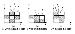
図2(a)〜(c)は、オブジェクト3を切り替えることなくフレーム間で移動させた場合の移動前と移動後の透過領域4と非透過領域5との関係を、スクリーン座標系を基準として示している。但し、オブジェクト3の各領域4,5はそれぞれ1画素相当の領域であり、各フレームにおけるオブジェクト3は4画素の矩形で代表した。便宜上、移動前のオブジェクト3の左下をスクリーン座標系の原点とした。破線は移動前のオブジェクト3を、太線は移動後のオブジェクト3をそれぞれ示している。
【0025】
図2(b)及び(c)の例から明らかなように、フレーム間でオブジェクト3がX軸方向又はY軸方向に1画素だけ移動した場合、その移動に伴って透過領域4と非透過領域5とはスクリーン座標系においてそれぞれ1画素ずつ移動する。従って、オブジェクト3上で透過領域4と非透過領域5とを交替させなくても、移動前に透過領域4と一致していた画面上の領域が移動後は非透過領域5と一致し、移動前に非透過領域5と一致していた画面上の領域が移動後は透過領域4と一致している。従って、これらの場合オブジェクト3A,3Bの切り替えは不要となる。一方、図2(a)から明らかなように、フレーム間でオブジェクト3がX軸方向及びY軸方向にそれぞれ1画素ずつ移動した場合には、上述したような透過領域4と非透過領域5との入れ替えは生じない。従って、この場合には、オブジェクト3A,3Bを切り替えてオブジェクト3上で透過領域4と非透過領域5とを交替させる必要がある。オブジェクト3が2画素以上移動した場合も同様に考えればよい。すなわち、移動前のフレームにおいて透過領域4と一致した画面上の領域が移動後のフレームにて領域4,5の交替がないと仮定した場合に透過領域4と再度一致する否かを判断し、一致する場合には移動後のフレームにおいて領域4,5の交替を実行し、一致しない場合には移動後のフレームにおいて領域4,5の交替を実行しないようにすればよい。
【0026】
オブジェクト3A,3Bを切り替えるか否かの判断は、領域4,5がいずれも1画素で構成されているという前提の下で、フレーム間におけるオブジェクト3のX−Y軸方向の移動量をそれぞれ△X、△Yとしたときに両者の和(△X+△Y)に基づいて行うことができる。すなわち、移動量の和(△X+△Y)を二進数で演算し、その最下位の桁が変化しているときはオブジェクト3A,3Bの切り替えが不要で、変化していないときはオブジェクト3A,3Bの切り替えが必要と判断すればよい。
【0027】
次に、上記の画像形成方法を実現する具体的な装置及び処理方法を図3及び図4を参照して説明する。本発明の画像の形成方法は様々な分野の画像処理において利用できるものであるが、以下では、一例としてコンピュータを利用した携帯型のゲーム機にて本発明の画像形成方法を実施する例を説明する。
【0028】
図3はコンピュータを利用した典型的なゲーム機の制御系のブロック図である。周知のように、コンピュータとしてのゲーム機10は、外部記憶装置(例えば半導体メモリを内蔵したカセット型の記憶装置)23に記録されたゲーム用プログラムに従って所定のゲームを実行する。ゲーム機10は、マイクロプロセッサを主体として構成されたCPU11と、そのCPU11に対する主記憶装置としてのROM12及びRAM13と、CPU11からの指示に基づいて画像処理及び音声処理に適した処理を行う画像処理装置14及びサウンド処理装置16とを有している。ROM12には、ゲーム機10の全体の動作制御に必要なプログラムとしてのオペレーティングシステムが書き込まれる。RAM13には外部記憶装置23から読み取ったゲーム用のプログラムやデータが必要に応じて書き込まれる。画像処理装置14はCPU11からの指示に従ってビデオメモリ15上に所定の画像をレンダリングしたり、そのレンダリングされた画像のデータを所定のビデオ再生信号に変換して所定のタイミングでモニタ19に出力する。モニタ19には好適には液晶モニタが使用される。
【0029】
ゲーム機によっては、画像処理装置14に高度な画像処理演算を実行するグラフィックスアクセラレータ機能が搭載されることもあり、CPU11及び画像処理装置14によってそれぞれどのような処理を負担するかはハードウエアの構成に依存して大きく相違する。そこで、本実施形態では、CPU11及び画像処理装置14を一体のコンピュータとみなして説明を続ける。ビデオメモリ15は画像処理装置14に描画専用のメモリとして設けられた例を示しているが、メインメモリとしてのRAM13上にビデオメモリが確保されてもよい。サウンド処理装置16は、外部記憶装置23から読み出された音声、楽音等のデータや音源データ等を再生してスピーカ20から出力させる。
【0030】
さらに、CPU11にはバス24を介して入力装置22及び通信制御装置24がそれぞれ接続される。通信制御装置24は通信インターフェース25を介して適当な通信手段(例えば携帯電話)と接続され、所定のネットワークを介したデータ通信を制御する。以上の構成はあくまで一例であり、本発明の画像の形成方法が適用されるコンピュータの構成は適宜変更されてよい。
【0031】
外部記憶装置23に記録されるゲーム用プログラムには、画像形成方法を実現するためのオブジェクト描画用プログラムが含まれる。また、外部記憶装置23にはゲーム用プログラムにて使用される各種のデータが記憶されるが、そのデータには上述したオブジェクト3A、3Bを描画するために必要なオブジェクト描画用データが含まれる。例えば、オブジェクト3A,3Bをそれぞれ適当なフォーマットの画像データとして予め用意しておくことができる。
【0032】
オブジェクト描画用プログラムは、1フレームの画像データを生成する処理において、本発明に従ってオブジェクトを描画する必要がある場合に呼び出されてCPU11により実行される。以下、図4を参照してそのオブジェクト描画用プログラムによる処理の概要を説明する。なお、図1及び図2に示した方法によるオブジェクトの描画に拘わる部分以外の処理には公知の技術をそのまま利用することができ、本明細書ではそれらの説明を省略する。
【0033】
図4の処理では、まず次のフレームにおけるオブジェクト3のスクリーン座標系におけるX、Y座標を取得する(ステップS1)。オブジェクト3の位置はゲームの進行状況に基づいて演算される。例えば、プレイヤーが操作するオブジェクト又はそのオブジェクトに関連して位置が定まるべきオブジェクトであれば、入力装置22に対するプレイヤーの操作が参照されてオブジェクトの位置が決まる。次に、オブジェクト3のX,Y座標を二進数で加算し(ステップS2)、求めた値を前回の加算値と比較する(ステップS3)。前回の加算値と今回の加算値との最下位のビットが変化しているか否か判断し(ステップS4)、変化していないときは次のフレームにて描画すべきオブジェクト3を切り替える(ステップS5)。つまり、前回のフレームでオブジェクト3Aが描画された場合は次のフレームでオブジェクト3Bを描画すべきオブジェクトとして選択し、前回のフレームでオブジェクト3Bが描画された場合は次のフレームでオブジェクト3Aを描画すべきオブジェクトとして選択する。この選択結果に基づいてオブジェクト3を描画し(ステップS6)、その後、一つのオブジェクトに対する描画処理を終了する。ステップS4で最下位のビットが変化していると判断したときはステップS5をスキップし、前回のフレームと同一のオブジェクト3をステップS6にて描画する。
【0034】
なお、本実施形態では、オブジェクト3を背景2と合成して描画する半透明処理を使用していないので、上記のように、半透明処理が指定された場合に、一番手前の半透明オブジェクトと背景とを合成するだけで中間のオブジェクトを省略するような描画機能を搭載したゲーム機にこれを適用した場合に好適である。すなわち、図1に示すようにオブジェクト3と背景2との間に他のオブジェクト6が配置された場合、オブジェクト3を半透明オブジェクトとして描画すればオブジェクト6そのものが消えてしまうが、本実施形態ではオブジェクト3を半透明として描く必要がないので、背景2とオブジェクト3との間にオブジェクト6が正しく描画される。オブジェクト6をさらに本発明の方法に従って描画した場合には、オブジェクト6の背後に背景2を観察することができる。
【0035】
以上の実施形態では、透過領域4と非透過領域5との配置が反転する2枚のオブジェクト3A、3Bをそれぞれオブジェクト描画用データとして予め用意し、それらを適宜切り替えて描画する手順を説明したが、本発明はそのような例に限らない。例えば、オブジェクトのデータを演算処理によって生成する場合においても、フレーム間で透過領域と非透過領域とが切り替わるようにそのオブジェクトの生成用のプログラムを調整すれば本発明の画像の形成方法を実施することができる。
【0036】
上記の実施形態では透過領域4及び非透過領域5の形状をそれぞれ矩形としたが、透過領域4と非透過領域5とが交互に配置される限りは矩形以外の形状でもよい。例えばハニカム状に透過領域4と非透過領域5とを並べてもよい。一方向にのみ透過領域4と非透過領域5とを交互に並べてもよい。つまり、透過領域4と非透過領域5とを互いに平行なストライプ状に配置してもよい。このように透過領域4と非透過領域5とを1画素相当以外の大きさに設定した場合には、透過領域と非透過領域との交替を行うか否かの判断において図4に示した方法をそのまま使用することはできない。しかしながら、透過領域と非透過領域とを規則的に配置している限りは、オブジェクトの一部を判断対象として抽出し、一のフレームにおいてその抽出された部分に含まれる透過領域と一致した画面上の領域が他のフレームにて透過領域と非透過領域との交替がないと仮定した場合に再び透過領域と一致する否かを検査し、その結果に基づいて、判断対象として抽出されなかった部分を含めて透過領域と非透過領域とを交替させるか否かを判断すればよい。
【0037】
【発明の効果】
以上に説明したように、本発明によれば、オブジェクトの透過領域と非透過領域とを複数のフレーム間で交替させるので、オブジェクト及びその背景の見えている部分が複数フレーム間で動的に変化するようになり、ユーザーが透過領域と非透過領域との見え方の相違に気付きにくくなって、画像のざらつき感が解消される。これにより、アルファブレンディング法のような合成処理を行わなくても、オブジェクトを半透明状に表示させることができ、しかも、画像の品質も高めることができる。
【図面の簡単な説明】
【図1】本発明の画像の形成方法の概要を示す図。
【図2】図1のオブジェクトの位置の変化と、透過領域及び非透過領域との関係を示す図。
【図3】本発明の画像の形成方法を実現する装置の一例としてのゲーム機のブロック図。
【図4】図3のゲーム機にて実行されるオブジェクト描画処理の手順を示すフローチャート。
【符号の説明】
1 スクリーン
2 背景
3,3A,3B オブジェクト
4 透過領域
5 非透過領域
10 ゲーム機
11 CPU
14 画像処理装置[0001]
BACKGROUND OF THE INVENTION
The present invention relates to an image display method for forming an image for displaying a background through an object.
[0002]
[Prior art]
As techniques for displaying a background through an object displayed on a game screen, methods such as an alpha blending method and addition synthesis are known. Due to improvements in computer processing capabilities, the number of models equipped with such image processing functions is increasing in the field of personal game consoles. However, the details of the functions differ depending on the ability required of the game machine. In general, stationary game machines are equipped with advanced image processing functions for forming high-quality images, while portable game machines have image processing functions for the purpose of reducing the burden of image processing. May be limited. As an example of such a restriction, when multiple semi-transparent objects overlap, ignore the intermediate object and draw only the semi-transparent object that should be drawn in the foreground background image. There is also a game machine.
[0003]
[Problems to be solved by the invention]
However, when only the foremost translucent object is combined with the background image as described above, drawing of the intermediate object may be omitted and an unnatural image may be formed. For example, in a scene where semi-transparent smoke is displayed as an object in the foreground, only that smoke is combined with the background image, so the drawing of characters and the like existing between the smoke and the background image is omitted. May disappear from the game screen.
[0004]
On the other hand, as a method of making an object visible without combining images, a transparent area and a non-transparent area are set to alternately form one or several images on an object to be overlaid. A process is also known in which a background image can be observed through a transmissive region. However, this method has a drawback in that the difference in appearance between the transparent area and the non-transparent area of the object is conspicuous depending on the size of the transmissive area and the non-transparent area, and the image is rough.
[0005]
Accordingly, the present invention provides an image forming method capable of displaying an object in a translucent state without performing synthesis with the background and improving the image quality, and a program used therefor. With the goal.
[0006]
[Means for Solving the Problems]
The present invention will be described below. In order to facilitate understanding of the present invention, reference numerals in the accompanying drawings are appended in parentheses, but the present invention is not limited to the illustrated embodiment.
[0007]
According to the image forming method of the present invention, an object (3) in which a transmissive region (4) and a non-transmissive region (5) are alternately provided in at least one direction is used, and the transmissive region and the non-transmissive region are at least partially formed. Draw over the frame in front of the predetermined background (2) over a plurality of frames.An image forming method for detecting a change in the position of the object between one frame and another frame thereafter, and controlling the change between the transmissive area and the non-transmissive area based on the change.This solves the above-described problems.
[0008]
According to the present invention, since the background of the object is observed through the transmissive area, the object itself is represented by the non-transmissive area, so that the object can be displayed in a translucent state. Since the transmissive region and the non-transmissive region are alternated between a plurality of frames, the difference in appearance between the transmissive region and the non-transmissive region becomes inconspicuous as compared with the case where each region is fixed. In other words, when the transparent area and the non-transparent area are fixed, the same part of the object in the foreground and the background are always visible, making it easier for the user to notice the difference in appearance. I can feel it. However, according to the method of the present invention, the visible portion of the object and its background is dynamically changed between a plurality of frames by alternating the transparent region and the non-transparent region between frames. As a result, it becomes difficult for the user to notice the difference in appearance between the transmissive region and the non-transmissive region, and the feeling of roughness is eliminated. In particular, when an object or the like is displayed on a display device having a relatively slow reaction speed (speed at which display contents are switched), such as a liquid crystal monitor, the user can reduce the period of replacement between the transmissive area and the non-transmissive area. The distinction between the transparent region and the non-transparent region is not felt at all, and the object placed in front is given an impression that it is translucent over the entire surface.
[0009]
The image forming method of the present invention can be applied to a case where an object moves within the screen as in a game screen, and a case where the object is stationary on the screen. However, when the position of the object changes, the transparent area and the non-transparent area may move to change the visible portion of the background. In such a case, if the transparent area and the non-transparent area are switched, the background can be seen instead. There is a case where the effect of the present invention is offset due to no change in the portion. Therefore, especially when the object moves, a change in the position of the object between one frame and the other frame thereafter is detected, and the transmissive area and the non-transmissive area are switched based on the change. It is desirable to control.
[0010]
In the process of controlling the replacement, it is determined whether or not the area on the screen that matches the transparent area in the one frame matches the transparent area again when it is assumed that there is no replacement in the other frame. If they match, the replacement may be executed in the other frame, and if they do not match, the replacement may not be executed in the other frame. In this case, the area on the screen that matches the transparent area in one frame matches the non-transparent area in the other frame, and the area on the screen that matches the non-transparent area in the other frame. In this frame, it matches the transmission region, so that the effect of the present invention can be exhibited to the maximum.
[0011]
In particular, when the transmissive region and the non-transmissive region are alternately provided in the vertical and horizontal directions one pixel at a time, the vertical direction and the horizontal direction indicating the position of the object on the screen in the process of controlling the replacement A value obtained by adding the coordinate values in the binary number is calculated for each of the one frame and the other frame, and when the least significant digit in each addition value is not changed, the replacement is performed in the other frame. If it has been changed, the alternation may not be executed in the other frame. By performing such processing, it is possible to easily determine whether or not the area on the screen that matches the transmissive area in one frame matches the transmissive area again when it is assumed that there is no replacement in another frame.
[0012]
The one frame and the other frame are preferably continuous frames. As a result, it is determined whether or not the transmissive area and the non-transmissive area are switched for each frame. Therefore, the replacement cycle of both areas is shortened as much as possible and is equivalent to an image that has been subjected to advanced translucent processing. A quality image can be formed.
[0013]
The image forming program according to the present invention includes an object (3) in which transparent regions (4) and non-transparent regions (5) are alternately provided in at least one direction., Over a plurality of frames while at least partially alternating the transmissive region and the non-transmissive regionBefore the predetermined background (2)RepeatedlyA program for causing a computer to execute a drawing process,Detects a change in the position of the object between one frame and the other frames thereafter, and controls the change between the transmissive area and the non-transmissive area based on the change.It is comprised so that it may do.
[0014]
By executing this program on a computer, the image forming method of the present invention can be realized.
[0015]
The program of the present invention may include the following aspects.
[0016]
In the process of controlling the replacement, it is determined whether or not the area on the screen that matches the transparent area in the one frame matches the transparent area again when it is assumed that there is no replacement in the other frame. In addition, the program may be configured so that the replacement is executed in the other frame if they match, and the replacement is not executed in the other frames if they do not match. The program is configured on the assumption that the transparent region and the non-transparent region are alternately provided in the vertical and horizontal directions one by one, and in the process of controlling the replacement, the vertical direction and the horizontal direction indicating the position of the object on the screen. A value obtained by adding the coordinate values in the direction in binary numbers is calculated for each of the one frame and the other frame, and when the least significant digit in each addition value is not changed, the replacement is performed in the other frame. The program may be configured not to execute the alternation in the other frame when the change is made. The one frame and another frame may be a continuous frame.
[0017]
The background in the present invention only needs to be observed behind an object provided with a transparent region and a non-transparent region according to the present invention, and other objects, textures, and other various elements are treated as a background. Can do. The present invention is not limited to the case where all of the transparent and non-transparent areas of the object are replaced, but also includes the case where they are partially replaced. All of the transmissive area and the non-transmissive area may be partially replaced, or a part of the transmissive area and the non-transmissive area of the object may be completely or partially replaced.
[0018]
In the image forming apparatus according to the present invention, an object in which transmissive areas and non-transmissive areas are alternately provided in at least one direction is spread over a plurality of frames while at least partially replacing the transmissive areas and the non-transmissive areas. An image forming apparatus that draws an image in front of a predetermined background, detects a change in the position of the object between one frame and another frame thereafter, and determines whether or not the transparent region is It is characterized by controlling the replacement with the transmission region. With this image forming apparatus, the image forming method of the present invention can be realized. Further, in the processing for controlling the replacement of the image forming apparatus according to the present invention, it is assumed that the area on the screen that coincides with the transmission area in the one frame does not have the replacement in the other frame. It is determined whether or not the region matches again. If the region matches, the replacement is performed in the other frame, and if the region does not match, the replacement may not be performed in the other frame.
[0019]
DETAILED DESCRIPTION OF THE INVENTION
FIG. 1 is a diagram showing an example of an image forming method according to the present invention. FIG. 1A shows a state in which a rectangular background 2 is drawn on a
[0020]
As shown in FIG. 1B, the
[0021]
When the
[0022]
Therefore, in the present invention, as shown in FIG. 1C, an object 3B obtained by inverting the
[0023]
By the way, when the position of the
[0024]
2A to 2C show the relationship between the
[0025]
As is clear from the examples of FIGS. 2B and 2C, when the
[0026]
Whether or not the
[0027]
Next, a specific apparatus and processing method for realizing the above-described image forming method will be described with reference to FIGS. The image forming method of the present invention can be used in image processing in various fields. Hereinafter, as an example, an example in which the image forming method of the present invention is implemented in a portable game machine using a computer will be described. To do.
[0028]
FIG. 3 is a block diagram of a control system of a typical game machine using a computer. As is well known, the game machine 10 as a computer executes a predetermined game in accordance with a game program recorded in an external storage device (for example, a cassette-type storage device incorporating a semiconductor memory) 23. The game machine 10 includes a
[0029]
Depending on the game machine, the
[0030]
Furthermore, an input device 22 and a
[0031]
The game program recorded in the
[0032]
The object drawing program is called and executed by the
[0033]
In the process of FIG. 4, first, the X and Y coordinates in the screen coordinate system of the
[0034]
In the present embodiment, since the translucent process for drawing the
[0035]
In the above embodiment, the procedure has been described in which two
[0036]
In the above embodiment, the shapes of the
[0037]
【The invention's effect】
As described above, according to the present invention, the transparent region and the non-transparent region of the object are interchanged between a plurality of frames, so that the visible portion of the object and its background changes dynamically between the plurality of frames. As a result, it becomes difficult for the user to notice the difference in appearance between the transmissive region and the non-transmissive region, and the rough feeling of the image is eliminated. Thus, the object can be displayed in a translucent state without performing a synthesizing process such as the alpha blending method, and the image quality can be improved.
[Brief description of the drawings]
FIG. 1 is a diagram showing an outline of an image forming method of the present invention.
FIG. 2 is a diagram illustrating a relationship between a change in the position of the object in FIG. 1 and a transmissive region and a non-transmissive region.
FIG. 3 is a block diagram of a game machine as an example of an apparatus for realizing the image forming method of the present invention.
4 is a flowchart showing a procedure of object drawing processing executed in the game machine of FIG. 3;
[Explanation of symbols]
1 screen
2 Background
3,3A, 3B object
4 Transmission area
5 Non-transparent area
10 game consoles
11 CPU
14 Image processing device
Claims (10)
Priority Applications (4)
| Application Number | Priority Date | Filing Date | Title |
|---|---|---|---|
| JP2001143209A JP3645829B2 (en) | 2001-05-14 | 2001-05-14 | Image forming method and image forming program |
| DE60212900T DE60212900T2 (en) | 2001-05-14 | 2002-05-09 | Image generation method and computer program therefor |
| EP02253246A EP1258836B1 (en) | 2001-05-14 | 2002-05-09 | Image forming method, and computer program for forming image |
| US10/143,220 US6833841B2 (en) | 2001-05-14 | 2002-05-09 | Image forming method, computer program for forming image, and image forming apparatus |
Applications Claiming Priority (1)
| Application Number | Priority Date | Filing Date | Title |
|---|---|---|---|
| JP2001143209A JP3645829B2 (en) | 2001-05-14 | 2001-05-14 | Image forming method and image forming program |
Publications (2)
| Publication Number | Publication Date |
|---|---|
| JP2002342774A JP2002342774A (en) | 2002-11-29 |
| JP3645829B2 true JP3645829B2 (en) | 2005-05-11 |
Family
ID=18989387
Family Applications (1)
| Application Number | Title | Priority Date | Filing Date |
|---|---|---|---|
| JP2001143209A Expired - Fee Related JP3645829B2 (en) | 2001-05-14 | 2001-05-14 | Image forming method and image forming program |
Country Status (4)
| Country | Link |
|---|---|
| US (1) | US6833841B2 (en) |
| EP (1) | EP1258836B1 (en) |
| JP (1) | JP3645829B2 (en) |
| DE (1) | DE60212900T2 (en) |
Families Citing this family (8)
| Publication number | Priority date | Publication date | Assignee | Title |
|---|---|---|---|---|
| JP2006311057A (en) * | 2005-04-27 | 2006-11-09 | Fujinon Corp | Image processing apparatus |
| US7782340B2 (en) * | 2006-07-10 | 2010-08-24 | Aten International Co., Ltd. | Multiple video signals coexisting system and method thereof |
| US20090058863A1 (en) * | 2007-09-04 | 2009-03-05 | Apple Inc. | Image animation with transitional images |
| JP2010190955A (en) * | 2009-02-16 | 2010-09-02 | Toshiba Corp | Voice synthesizer, method, and program |
| FR2948483B1 (en) * | 2009-07-23 | 2012-02-03 | Airbus Operations Sas | METHOD FOR DISPLAYING AN IMAGE ON A SCREEN OF AN AIRCRAFT |
| US9069433B2 (en) * | 2012-02-10 | 2015-06-30 | Randall Hunt | Method and apparatus for generating chain-link fence design |
| KR101932595B1 (en) | 2012-10-24 | 2018-12-26 | 삼성전자주식회사 | Image processing apparatus and method for detecting translucent objects in image |
| CN112308088A (en) * | 2020-09-16 | 2021-02-02 | 广州忆游科技有限公司 | Method for intelligently screening full-transparent pictures |
Family Cites Families (6)
| Publication number | Priority date | Publication date | Assignee | Title |
|---|---|---|---|---|
| JPS62139081A (en) * | 1985-12-13 | 1987-06-22 | Canon Inc | Formation of synthetic image |
| JP3037161B2 (en) * | 1996-11-08 | 2000-04-24 | 日本電気アイシーマイコンシステム株式会社 | Graphic image display device and graphic image display method |
| US5896131A (en) * | 1997-04-30 | 1999-04-20 | Hewlett-Packard Company | Video raster display with foreground windows that are partially transparent or translucent |
| US6151030A (en) * | 1998-05-27 | 2000-11-21 | Intel Corporation | Method of creating transparent graphics |
| US6088018A (en) * | 1998-06-11 | 2000-07-11 | Intel Corporation | Method of using video reflection in providing input data to a computer system |
| US6483503B1 (en) * | 1999-06-30 | 2002-11-19 | International Business Machines Corporation | Pixel data merging apparatus and method therefor |
-
2001
- 2001-05-14 JP JP2001143209A patent/JP3645829B2/en not_active Expired - Fee Related
-
2002
- 2002-05-09 US US10/143,220 patent/US6833841B2/en not_active Expired - Fee Related
- 2002-05-09 EP EP02253246A patent/EP1258836B1/en not_active Expired - Lifetime
- 2002-05-09 DE DE60212900T patent/DE60212900T2/en not_active Expired - Lifetime
Also Published As
| Publication number | Publication date |
|---|---|
| DE60212900T2 (en) | 2006-11-30 |
| EP1258836B1 (en) | 2006-07-05 |
| US20020167535A1 (en) | 2002-11-14 |
| EP1258836A3 (en) | 2004-03-03 |
| US6833841B2 (en) | 2004-12-21 |
| JP2002342774A (en) | 2002-11-29 |
| EP1258836A2 (en) | 2002-11-20 |
| DE60212900D1 (en) | 2006-08-17 |
Similar Documents
| Publication | Publication Date | Title |
|---|---|---|
| JP3372832B2 (en) | GAME DEVICE, GAME IMAGE PROCESSING METHOD, AND COMPUTER-READABLE RECORDING MEDIUM CONTAINING GAME IMAGE PROCESSING PROGRAM | |
| JP3770497B2 (en) | Portable game machine and game program | |
| JP4382117B2 (en) | Image generating apparatus and method, program, and recording medium | |
| JP4067138B2 (en) | Game device | |
| JP3761559B1 (en) | Image output method | |
| JPWO2008015978A1 (en) | Video display device and video display method | |
| JP2006092156A (en) | Program, information storage medium and image generation device | |
| JP4383241B2 (en) | An image processing system that increases the number of drawn polygons | |
| JP2009031947A (en) | Image generation device, method, program, and recording medium | |
| JP3645829B2 (en) | Image forming method and image forming program | |
| JP3442736B2 (en) | Image processing apparatus, image processing method, and information storage medium | |
| JP2007296218A (en) | Program and device for game image processing | |
| JP3604312B2 (en) | Computer-readable recording medium having recorded video game program, object drawing method in video game, and video game apparatus | |
| JP6527641B2 (en) | Image processing apparatus and superimposed image generation method | |
| US6339430B1 (en) | Video game machine and method for changing texture of models | |
| JP3527672B2 (en) | Computer-readable recording medium recording a three-dimensional computer image processing program, shadow drawing processing method, and video game apparatus | |
| JP2002024849A (en) | Three-dimensional image processing device and readable recording medium with three-dimensional image processing program recorded thereon | |
| JP3502796B2 (en) | 3D model display method and apparatus in video game, game apparatus, and computer-readable recording medium storing 3D model display program for video game | |
| JP4303518B2 (en) | Program, information storage medium, and image generation apparatus | |
| JP3579680B2 (en) | Image processing apparatus and program | |
| JP3729187B2 (en) | Image display device | |
| JP2000185179A (en) | Image processor and recording medium | |
| JP4447417B2 (en) | GAME DEVICE, PROGRAM, AND COMPUTER CONTROL METHOD | |
| JP5464630B2 (en) | Image display device | |
| JP2008234681A (en) | Video game device, image display device and method, moving image display device and method, and recording medium |
Legal Events
| Date | Code | Title | Description |
|---|---|---|---|
| A131 | Notification of reasons for refusal |
Free format text: JAPANESE INTERMEDIATE CODE: A131 Effective date: 20040921 |
|
| A521 | Request for written amendment filed |
Free format text: JAPANESE INTERMEDIATE CODE: A523 Effective date: 20041109 |
|
| TRDD | Decision of grant or rejection written | ||
| A01 | Written decision to grant a patent or to grant a registration (utility model) |
Free format text: JAPANESE INTERMEDIATE CODE: A01 Effective date: 20050201 |
|
| A61 | First payment of annual fees (during grant procedure) |
Free format text: JAPANESE INTERMEDIATE CODE: A61 Effective date: 20050204 |
|
| R150 | Certificate of patent or registration of utility model |
Free format text: JAPANESE INTERMEDIATE CODE: R150 |
|
| S111 | Request for change of ownership or part of ownership |
Free format text: JAPANESE INTERMEDIATE CODE: R313111 |
|
| R350 | Written notification of registration of transfer |
Free format text: JAPANESE INTERMEDIATE CODE: R350 |
|
| FPAY | Renewal fee payment (event date is renewal date of database) |
Free format text: PAYMENT UNTIL: 20090210 Year of fee payment: 4 |
|
| FPAY | Renewal fee payment (event date is renewal date of database) |
Free format text: PAYMENT UNTIL: 20090210 Year of fee payment: 4 |
|
| S531 | Written request for registration of change of domicile |
Free format text: JAPANESE INTERMEDIATE CODE: R313531 |
|
| FPAY | Renewal fee payment (event date is renewal date of database) |
Free format text: PAYMENT UNTIL: 20090210 Year of fee payment: 4 |
|
| R350 | Written notification of registration of transfer |
Free format text: JAPANESE INTERMEDIATE CODE: R350 |
|
| FPAY | Renewal fee payment (event date is renewal date of database) |
Free format text: PAYMENT UNTIL: 20090210 Year of fee payment: 4 |
|
| FPAY | Renewal fee payment (event date is renewal date of database) |
Free format text: PAYMENT UNTIL: 20100210 Year of fee payment: 5 |
|
| FPAY | Renewal fee payment (event date is renewal date of database) |
Free format text: PAYMENT UNTIL: 20110210 Year of fee payment: 6 |
|
| FPAY | Renewal fee payment (event date is renewal date of database) |
Free format text: PAYMENT UNTIL: 20110210 Year of fee payment: 6 |
|
| FPAY | Renewal fee payment (event date is renewal date of database) |
Free format text: PAYMENT UNTIL: 20120210 Year of fee payment: 7 |
|
| FPAY | Renewal fee payment (event date is renewal date of database) |
Free format text: PAYMENT UNTIL: 20130210 Year of fee payment: 8 |
|
| FPAY | Renewal fee payment (event date is renewal date of database) |
Free format text: PAYMENT UNTIL: 20130210 Year of fee payment: 8 |
|
| RD04 | Notification of resignation of power of attorney |
Free format text: JAPANESE INTERMEDIATE CODE: R3D04 |
|
| FPAY | Renewal fee payment (event date is renewal date of database) |
Free format text: PAYMENT UNTIL: 20140210 Year of fee payment: 9 |
|
| R250 | Receipt of annual fees |
Free format text: JAPANESE INTERMEDIATE CODE: R250 |
|
| R250 | Receipt of annual fees |
Free format text: JAPANESE INTERMEDIATE CODE: R250 |
|
| LAPS | Cancellation because of no payment of annual fees |