JP3645748B2 - Solder defect inspection device - Google Patents
Solder defect inspection device Download PDFInfo
- Publication number
- JP3645748B2 JP3645748B2 JP17933899A JP17933899A JP3645748B2 JP 3645748 B2 JP3645748 B2 JP 3645748B2 JP 17933899 A JP17933899 A JP 17933899A JP 17933899 A JP17933899 A JP 17933899A JP 3645748 B2 JP3645748 B2 JP 3645748B2
- Authority
- JP
- Japan
- Prior art keywords
- inspection
- signal
- input
- terminal
- output
- Prior art date
- Legal status (The legal status is an assumption and is not a legal conclusion. Google has not performed a legal analysis and makes no representation as to the accuracy of the status listed.)
- Expired - Fee Related
Links
Images


Landscapes
- Testing Of Short-Circuits, Discontinuities, Leakage, Or Incorrect Line Connections (AREA)
- Tests Of Electronic Circuits (AREA)
Description
【0001】
【発明の属する技術分野】
本発明は、半田付不良検査装置、特に電子デバイスや部品の半田付実装後に半田接続箇所の目視検査が困難な場合、例えばICパッケージの信号入力端子の半田付不良の検査装置に関する。
【0002】
【従来の技術】
最近の電子機器や電子応用機器のエレクトロニクス部分にはIC(半導体集積回路)を多用し、斯るデバイスを回路基板に半田付実装するのが一般的である。
【0003】
斯るエレクトロニクス部分又は回路の半田不良検査方法は、一般にバンダリ(境界)スキャンやX線検査等の量産時に行われる専用の検査装置を用いる。近年、ICデバイス等は実装密度を上げる為にBGA(ボールグリッドアレイ)等の実装が採用されている。BGAでは半田接続箇所がパッケージ底面側であるので、外部から見ることができず目視検査は困難である。しかし、斯るBGA接続された電子デバイス等であっても半田不良検査可能な半田不良検査方法の開発が要求されている。
【0004】
この要求に応える為に、例えば特開平9−26463号公報の「テスト回路を内蔵した集積回路」が提案されている。信号端子が回路基板上の浮遊容量を持つ配線に正常に接続されているときと、接続されていないときとの容量差を充電電流を供給することで測定する。これを論理信号のパルス幅の差に変換して出力することにより半田付欠陥を検知する。
【0005】
また、特開平7−159493号公報の「半導体デバイスの検査方法」には、先ず被検査ピンに入力されるテストデータを記憶素子に入力し、次に記憶素子をシフトレジスタとして構成してテストデータをテスト用ピンに出力させることにより、半田付の良否を特定することを開示している。
【0006】
更に、特開平4−337646号公報の「集積回路」には、1組の入力ピンと出力ピンをスルー状態にした上で、入力ピン側配線に所定の信号を印加して、出力ピン側配線に現れる信号を観測することにより半田付の良否を検査する技術を開示している。
【0007】
更にまた、特開平3−78670号公報の「検査機能付集積回路」には、検査モードになると検査パターン発生器からの検査パターンを、入出力ピンを問わず全ての被検査ピンに出力することにより半田付状態を確認する技術を開示している。
【0008】
最後に、特開平2−99877号公報の「集積回路部品及びその接続検査方法」には、接合検査モード時に各信号端子同士がトランジスタを介して電気的に接続され、基板上で各信号端子毎に引出された配線パターンにプロービングヘッドを圧接し、導通を測定して半田による接合状態を検査する技術を開示している。
【0009】
【発明が解決しようとする課題】
しかし、上述した第1、第3及び第4の従来技術では、被検査端子に他のデバイスの出力端子が接続されていると、自らのテストデータ出力信号と競合する為に他のデバイスを搭載前する前か、他のデバイスを電気的に切離した状態でなければ検査が行えないという問題がある。
【0010】
また、上述した第2及び第3の従来技術では、被検査端子に他のデバイスの出力端子が接続されていると、外部からのテストデータ入力信号と競合を起す為に、他のデバイス搭載前又は他のデバイスを電気的に切離した状態でなければ検査が行えないという問題がある。
【0011】
更に、上述した第3の従来技術では、出力ピンに入力した信号と違うパターンの信号が現れたとしても、入力ピンと出力ピンがスルー状態となっている為に、半田付不良の場所が入力側か出力側か、又は入出力両側かの判別ができないという問題がある。
【0012】
更にまた、上述した第5の従来技術では、外部で導通しているピン同士に対しては、内部を通して導通した場合と区別がつかない為に、検査不可能であるという問題がある。また、被検査端子に接続されている他のデバイスのピン全てを電気的に短絡してしまう為に、他のデバイスを破壊してしまう可能性がある。
【0013】
最後に、上述した第4の従来技術では、同時に複数本の端子を同じパターンのテスト信号で検査する為に、端子同士の短絡が検出できないという問題がある。
【0014】
本発明の第1の目的は、被検査端子に他のデバイスの出力端子が接続されていても、自らのテストデータ出力信号と競合を起こさず、他のデバイスを搭載した後でも他のデバイスを電気的に切離することなく検査実行可能な半田不良検査装置を提供することである。
【0015】
本発明の他の目的は、被検査端子に他のデバイスの出力端子が接続されていても外部からのテストデータ入力信号と競合することなく検査できる半田不良検査装置を提供することである。
【0016】
本発明のその他の目的は、検査の結果、不良が発見された場合に、半田不良の場所が入力側か、出力側か又は両方かの判別が可能である半田不良検査装置を提供することである。
【0017】
本発明の付加的な目的は、外部で導通しているピン同士に対しても不良箇所が検査できる半田不良検査装置を提供することである。
【0018】
本発明の別の目的は、被検査端子に接続されている他のデバイスを破壊することのない半田不良検査装置を提供することである。
【0019】
また、本発明の他の目的は、同時に複数本の端子をテストしても、端子同士の短絡が検出可能である半田不良検査装置を提供することである。
【0020】
【課題を解決するための手段】
前述の課題を解決するため、本発明による半田不良検査装置は、次のような特徴的な構成を採用している。
【0021】
(1) 複数の入力端子及び信号処理部を有する集積回路が回路基板等に正しく半田付けされているか検査する半田不良検査装置において、
前記集積回路は、前記入力端子からの前記信号処理回路に入力される本来外部より供給される複数の入力信号を受け、前記半田不良を検出する検査部と、該検査部の検査モード選択やタイミング制御を行う検査制御信号を出力する検査制御部とを有し、
前記検査部は、検査制御信号により検査モードが選択されると、前記複数の各入力信号と、前記複数の各入力信号に対してプルアップまたはプルダウン処理を施して得られる信号レベルとに基づいて半田不良を検出することを特徴とする半田不良検査装置。
【0022】
(2)前記検査部は、前記入力端子毎の検査結果を保持するフリップフロップを備え、前記検査制御部からの制御信号により1つの出力端子から順次検査結果を出力する上記(1)の半田不良検査装置。
【0023】
(3)前記検査制御部の制御信号は、制御端子を介して前記検査モードを外部より変更可能にする上記(1)の半田不良検査装置。
【0027】
【発明の実施の形態】
以下、本発明による半田不良検査装置の好適実施形態例を添付図を参照して詳細に説明する。
【0028】
図1は、本発明による半田不良検査装置の第1実施形態例を示す。検査対象の集積回路(以下ICという)1、検査対象入力端子5、6、検査制御用入力端子であるTEH7、TEL8、検査結果出力端子SDOUT9及び基準信号出力端子SCOUT10より構成される。
【0029】
IC1内には、このIC1の本来の機能を実行する為の信号処理部2のみならず、入力端子5、6の信号レベルを検査する為の検査部3及び検査制御部4を有する。入力端子5、6と信号処理部2間にはレシーバ11、12が設けられる。また、TEH端子7及びTEL端子8と検査制御部4間には、それぞれレシーバ13、14が設けられている。検査部3には、入力端子5、6が直接接続されると共に検査制御部4の出力が入力され、更にその出力はドライバ15、16を介して、それぞれSDOUT端子9及びSCOUT端子10に出力される。
【0030】
検査部3の検査結果は、SDOUT端子9及びSCOUT端子10を介して観測可能に構成されている。TEH端子7及びTEL端子8は、検査制御部4に接続され、検査モードの変更や検査の開始を示すトリガをIC1の外部から入力する為に使用される。検査制御部4で生成される信号は、検査部3に供給され、検査部3のモード選択やタイミング制御に使用される。
【0031】
次に、図2は、図1中の検査部3の詳細回路構成図である。この検査部3は、フリップフロップ(以下F/Fという)25、35、セレクタ36及びANDゲート37を主要構成要素として有する。F/F25のDin入力端子には、図1の入力端子5がレシーバ(バッファ)11を介して接続される。この入力端子5には、それぞれスイッチングトランジスタ21、22の一端が接続され、他端はそれぞれプルアップ抵抗20及びブルダウン抵抗23を介してVccと接地に接続される。同様に、F/F35のDin入力端子には、レシーバ12を介して入力端子6が接続される。この入力端子6には、スイッチングトランジスタ31、32、プルアップ抵抗30及びブルダウン抵抗33が接続される。
【0032】
レシーバ12の後段にはセレクタ36が接続され、F/F35のDin入力端子には、入力端子6の入力信号又はF/F25のDoutが入力されるようにする。両F/F25、35のCLK(クロック)端子には、CLK信号28が入力される。F/F35のDout出力端子からSDOUT9が出力される。また、ANDゲート37の入力端子には、CLK信号28とSFTE信号47が入力され、出力端子からSCOUT信号10が出力される。また、セレクタ36には選択信号(SFTE)47が入力される。
【0033】
スイッチングトランジスタ21、22、31、32の制御端子には、それぞれTSTH信号48、TSTL信号49が入力され、オン/オフ状態に制御される。スイッチングトランジスタ21、31は、それぞれ入力端子5、6が開放(オープン)状態のときオンとなり、信号レベルをH(ハイ)に維持する。他方、スイッチングトランジスタ22、32は、オンとなるとプルダウン抵抗23、33を介してプルダウンして、対応する入力端子5、6をL(ロー)レベルに維持する。プルアップ/プルダウン抵抗20、23、30、33は約50KΩである。
【0034】
次に、図2の動作を説明する。F/F25、35は、CLK信号28に同期してDin入力端子の状態を保持するD形F/Fであり、図2中には2個のF/Fのみを示すが、入力端子数に対応するF/Fを使用するものとする。そこでセレクタ36は、制御信号SFTE47に基づき、自己の入力端子の入力信号又は前段のF/FのDout出力端子の信号を選択してDin入力端子に入力する。ここで、セレクタ36はF/F25〜35で保持されているデータを最終段のF/F35のDout出力端子からSDOUT出力9としてシリアルデータとして出力される為にF/F25〜35をシフトレジスタとして機能させる働きをする。
【0035】
半田不良検査対象となる入力端子5、6が3本以上存在する場合には、セレクタ36は2段目以降最終段のF/F35までのDin入力端子に1対1で接続する。
【0036】
ANDゲート37は、CLK信号28をセレクタ切替制御用SFTE信号47でマスクすることにより、SDOUT出力9を外部から観測する際の基準(トリガ)信号となるSCOUT出力10を生成する為の回路である。CLK信号28は、検査部3及び検査制御部4の同期をとる為のクロック信号である。
【0037】
次に、図3を参照して、図1中の検査制御部4の詳細回路構成を説明する。この回路4は、検査制御用入力端子TEH7、TEL8にそれぞれ接続されたプルアップ抵抗41、40、XORゲート42、片側に反転入力のついたORゲート43、片側に反転入力のついたANDゲート44、カウンタ45及びNOTゲート(インバータ)46を有する。XORゲート42の出力は、ANDゲート44の非反転入力端子に入力される。ANDゲート44の出力は、クロック(CLK)信号28と共にカウンタ45に入力される。カウンタ45は、SFTE信号47を出力すると共に、この出力をANDゲート44の反転入力端子に入力する。ORゲート43は、TSTH信号48を出力すると共にNOTゲート46で反転してTSTL信号49を出力する。
【0038】
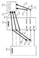
次に、図4に、本発明による半田不良検査方法の例、即ち図1に示すIC1を用いて入力端子の半田不良を検出する方法を説明する。図4中、IC61は、図1のIC1に相当する機能を有するICであり、ピン#1〜#3の3本の入力端子を有するものとする。ピン#3が上述したIC1の入力端子5に対応し、1段目のF/Fに接続されている。ピン#2は、図4で追加された入力端子であり、2段目のF/Fに接続されている。ピン#1は、上述のIC1の入力端子に相当し、最終段F/Fに接続されている。このIC61の前段に外部回路62を配置し、IC61のSDOUT及びSCOUT出力端子66、67にロジックアナライザ63等の測定器を接続する。
【0039】
外部回路62は、IC61の各端子#1〜#3及びCLK端子に必要とする信号を供給する。また、IC61のTEH及びTEL入力にもそれぞれ観測端子64、65を設け、更に接地(GND)端子69を設ける。IC61のTEL入力端子65は接続ケーブル68により接地され、観測端子66、67はそれぞれ接続ケーブル(又はプローグ)70、71によりロジックアナライザ63に接続した状態を図4に示す。
【0040】
次に、図1乃至図4の回路動作を説明する。先ず図1のIC1において、入力端子5、6から供給される信号は、通常状態では、レシーバ11、12を介して信号処理部2に送られて、IC1の本来の信号処理動作を行う。回路基板等に半田付実装されて半田不良検査時には、入力端子5、6の信号状態がレシーバ11、12を介さず直接検査部3へ入力される。検査部3では、送られて来た検査信号にプルアップ又はプルダウンのいずれかの処理を施して、その時の状態をSDOUT信号9を介して外部に出力する。
【0041】
もし、外部より入力端子5、6にHレベルが入力されている場合には、半田不良により正常に信号が送られていなければ検査部3でプルダウン処理を施すことにより該当する信号はLレベルとしてSDOUT出力9を出力する。同様に、外部から入力端子5、6にLレベルが供給されている場合に半田不良により正常に信号を伝えられていないと、検査部3でプルアップ処理をすることにより、該当する信号は、HレベルとしてSDOUT出力9を出力する。入力端子5、6へ入力する検査信号をプルアップ状態又はプルダウン状態のいずれかで検査するかは検査制御部4により判断される。
【0042】
次に、図2を参照して検査部3の動作を説明する。図5にスイッチングトランジスタ(以下単にスイッチという)21、22、31、32の動作状態を示す。スイッチ21、22、31、32は、TSTH信号48又はTSTL信号49がHレベルのとき導通状態となり、入力端子5又は6は、プルアップ抵抗20、30によりVccにプルアップ状態とされるか、プルダウン抵抗21、31により接地レベルにプルダウンされる。これにより、レシーバ11、12の入力端子をプルアップ又はプルダウンする。但し、プルアップ又はプルダウン抵抗20、23、30、33により、入力端子5、6が正常に半田付されている場合には、斯るプルアップ又はプルダウンが入力端子5、6への入力信号レベルに影響することはない。
【0043】
しかし、入力端子5又は6にLレベルが入力される場合、半田付不良があると、スイッチ21、31をオン(導通)とし、プルアップすると、レシーバ11、12にはHレベルが入力されるので、半田不良が検出可能である。逆に、入力端子5、6にHレベルを入力する場合に、スイッチ22、32をオンとしてプルダウンすると、入力端子5、6が半田不良の場合にはレシーバ11、12にはLレベルが入力されるので半田不良が検出できる。
【0044】
尚、スイッチ21、22、31、32の制御信号TSTH48、TSTL49は、同時にHレベルとなることはなく、プルアップとプルダウンとが競合することがないよう、後述する検査制御部4により制御される。
【0045】
次に、図2の検査部3で使用するF/F25、35の動作を図6に示す。レシーバ11、12の入力端子に入力された信号レベルは、クロック(CLK)信号28の立上がりでF/F25、35に保持される。これら入力端子5、6の状態は、次のCLK信号28の立上がりまでの間F/F25に保持される。また、F/F25、35に保持された状態は、Dout出力端子より出力される。図7はセレクタ36の動作を示す。セレクタ36は、制御信号SFTE47がLレベルのとき、レシーバ12の出力をF/F35のDin入力端子に入力する。他方、制御信号SFTE47がHレベルのとき、F/F25のDout出力がF/F35のDin入力端子に入力される。この制御信号SFTE47は、後述する検査制御部4の制御により、通常動作時にはLレベルになっている。
【0046】
従って、最終段のF/F35の状態、即ち入力端子6の検査結果がF/F35のDout出力端子からSDOUT信号9として出力され、図4のロジックアナライザ63等で観測可能である。ここで、前段のF/F25の状態、即ち入力端子5の検査結果を外部より観測する為には、後述する検査制御部4により制御信号SFTE47をHレベルとする。そこで、SFTE47がHレベルの間、セレクタ36の出力には、前段のF/F25のDout出力状態が現れる。これにより、次のCLK信号28の立上がりでF/F25の状態はF/F35に保持され、SDOUT出力9として出力される。このセレクタ36の動作により入力端子5の検査結果が外部から観測可能である。
【0047】
また、シリアルデータであるSDOUT出力9のビット位置を示す為に、ANDゲート37によりセレクタ36の制御信号SFTE47とCLK信号28の論理積を求め、SFTE47がHレベルの間CLK信号28をSCOUT出力10として出力する。これらSDOUT出力9とSCOUT出力10の観測により、何段目のF/Fのデータが出力されているかが判断可能である。
【0048】
次に、図3の検査制御部4の動作を説明する。外部よりTEH入力7及びTEL入力8に何も信号が与えられない場合、プルアップ抵抗40、41によりVccにプルアップされ、両信号状態をHレベルに保つ。この状態では、ORゲート43の出力はHレベルとなるので、TSTH信号48はHレベル、TSTL信号49はLレベルとなる。従って、入力端子5、6のスイッチ21、31がオン、スイッチ22、32がオフとなり、入力端子5、6はプルアップされる。この状態で、図1のIC1は、信号処理部2を使用する本来の動作を行う。
【0049】
次に、図3の検査制御部4のカウンタ45の動作状態を図8に示す。外部からTEH入力7にHレベル、TEL入力8にLレベルが与えられると(TEH入力7がLレベル、TEL入力8がHレベルの場合も同じ)、XORゲート42の出力はHレベルとなる。このとき、通常動作時には、SFTE47はLレベルであるので、ANDゲート44の出力はHレベルとなる。その結果、カウンタ45のCE入力がHレベルとなり、0であったカウント値は、CLK信号28の立上がりで1となる。同時に、カウンタ45のカウント値が0出ないことを示すNOT0出力であるSFTE47がHレベルとなる。カウンタ45は、カウント値が0でないとき、CE入力の状態に無関係にCLK信号28の立上がり毎にカウントアップを続ける。そして、予め設定された最大カウント値Nに到達すると、次のCLK信号28の立上がりでカウント値を0に戻し、NOT0出力(SFTE47)の状態をLレベルにする。上述した最大カウント値Nには、検査対象となる入力端子数に設定しておく。従って、図2の例では、カウント値は0、1、2の3通りの状態を持つことになる。
【0050】
図3の検査制御部4で生成された制御信号SFTE47は、上述の検査部3のSDOUT出力9のシフトアウト動作を行う。また、SCOUT出力10に2つの基準クロックパルスと1つのL、即ちインターバル状態を送出する。また、検出をプルアップ状態を行うことを示す(即ちスイッチ21、31をオン)TSTH48は、ORゲート43により生成され、検査をプルダウン状態で行うことを示す(即ちスイッチ22、32をオン)TSTL49はNOTゲート46より得る。これから明らかな如く、TSTH48とTSTL49とは相補状態であり、いずれか一方がHレベルのとき他方はLレベルである。
【0051】
外部よりTEH入力7をLレベル、TEL入力8にHレベルとすると、ORゲート43の出力、即ちTSTH48はHレベル、NOTゲート46の出力であるTSTL49はLレベルとなる。この状態は、入力端子5、6をプルアップ状態で検査し、外部からこれら入力端子5、6にLレベルが入力されている入力端子の半田不良検査をする為に行われる。
【0052】
逆に、TEH入力7にHレベル、TEL入力8にLレベルを与えるとORゲート43の出力、即ちTSTH48はLレベル、TSTL49はHレベルとなるので、プルダウン状態での半田不良検査を行う。これは、外部から入力端子5、6にHレベルが供給されている場合の半田不良検査をする為に行われる。この動作をまとめて図9に示す。
【0053】
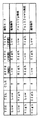
次に、図4の接続図に基づき、本発明による半田不良検査装置を図10のタイミングチャートを参照して説明する。図10中、(a)はフェーズ、(b)はCLK信号、(c)〜(e)はピン#1〜#3、(f)はTEH、(g)はTEL、(h)はピン番号、(i)はSCOUT信号、(j)はSDOUT信号、(k)はカウンタのカウント値、(l)はSFTE、(m)はTSTH及び(n)はTSTLである。
【0054】
リセット中等ある時点においてピン#1〜#3にそれぞれH、L、Hが供給されることが判っている。Hレベルが供給されるピン#1と#3に対してプルダウン検査を実施することを想定している。図10(a)のフェーズb中に電源投入が生じ、検査が開始されたとする。
【0055】
IC61のTEL入力端子65は、GND端子69に接地することによりLレベルが供給されている。また、TEH入力端子64には何も接続されていないので、IC61内部のプルアップによりHレベルとされている。従って、IC61内のTSTH信号48がL、TSTL信号49がHレベルとなり、ピン#1〜#3の入力端子にプルダウン検査が行われる。IC61の入力端子数は3本であるので、カウンタ45の最大カウント値Nは3に設定される。TEH入力がH、TEL入力がLになるとカウントアップが開始され、カウント値(図10の(k)参照)が1〜3の間SFTE(図10の(l)参照)がHとなる。図10中(a)のフェーズc〜e、g〜i、k〜m等がそれに相当する。この例では、TEL入力端子65がGND端子69に接続されている限りカウントアップ動作が継続される。
【0056】
SDOUT出力端子66には、フェーズCでCKK信号28が立上った時点でピン#1〜#3の状態がSCOUT出力端子67のクロックパルスに同期して順次出力される。この時点でのピン#1〜#3には、順番にH、L、Hが供給されている。従って、SDOUT出力の1つ目のパルスの時点、即ちフェーズCでのSDOUT出力はHレベルとなってピン#1の状態を出力する。それ以降は、2つ目のパルス時点、即ちフェーズdではLレベルとなってピン#2の状態を出力する。また、3つ目のパルス時点、即ちフェーズeではHレベルとなってピン#3の状態を出力する。カウント値が0となった時点ではSCOUT出力端子67のパルスがマスクされ、検査と検査の区切りを示す。図10中(h)のピン中にインターバルIとして示す。フェーズf、j、n等がそれに相当する。
【0057】
図10の例では、IC61のピン#1及び#3は、内部でプルダウンを行っているにも拘わらずSDOUT出力の該当部分にはHレベルが出力されている。これは、外部から供給されているHレベルがIC61内に正しく伝達されており、ピン#1、#3には半田不良がないことを意味する。
【0058】
次に、図11のタイミングチャートを参照して、図4の構成においてピン#1に半田不良があった場合の動作を説明する。図11中(a)〜(j)は、図10中の(a)〜(j)と同じである。上述のとおり、SDOUT出力端子66には、フェーズcでCLK信号28の立上がり時点におけるピン#1〜#3の状態がSCOUT出力端子67のクロックパルスに同期して順番に出力される。この時点でのピン#1〜#3には、順番にH、L、Hレベルが供給されている。従って、本来ならSCOUT出力の1つ目のパルスの時点で、即ちフェーズcでSDOUT出力端子66にはHレベルが出力される筈である。しかしピン#1が半田不良である為に外部からHレベルがIC61内に正しく伝達されずIC61内のプルダウンの為にフェーズcで図11(j)に示す如くLレベルとなる。
【0059】
そこで、SDOUT出力端子66の信号をロジックアナライザ63等で観測することで、IC61のピン#1では、外部よりHレベルが供給されているにも拘わらず内部プルダウンによりLレベルとされていることが判明する。従って、IC61のピン#1には、外部信号が正しく供給されず半田不良であることが判断できる。
【0060】
尚、上述の例にあってはTEL端子65をGND端子69に接続してプルダウン検査を行ったが、TEH端子64を接続ケーブル68によりGND端子69に接続して、プルアップ検査を行ってもよい。この場合には、外部よりLレベルが供給されているピン#2に対して半田不良が検査できる。更にまた、上述した例にあっては、検査制御回路4のTEH端子7及びTEL端子8にはプルアップ抵抗41、40を介してVccに常時プルアップされているが、ORゲート43及びNOTゲート46に適切な変更を加えることにより、内部プルダウン又は内部抵抗処理なしとすることも可能であること当業者には自明であろう。
【0061】
次に図12乃至図14を参照して、本発明による半田不良検査方法の第2実施形態例を説明する。図12は、この半田不良検査方法を実施する為の接続図を示す。図4の場合と同様に、IC81、外部回路82及びロジックアナライザ(測定器)83を使用する。IC81はピン#1〜#3、TEH端子84、TEL端子85、CLK端子、SDOUT端子86及びSCOUT端子87を有する。この例では、入力端子に供給される信号がH又はLに一定していない場合の検査方法である。この場合には、IC81のピン#1及び#2を接続ケーブル88、89によりそれぞれTEH端子84、TEL端子85に接続している。また、ロジックアナライザ83には、接続ケーブル(又はプローブ)90〜94を使用してそれぞれIC81のピン#1〜#3、SDOUT端子86及びSCOUT端子87に接続されている。
【0062】
図13は、図12の動作を説明するタイミングチャートであり、図13の(a)〜(n)は、上述した図10の(a)〜(n)と対応する。この例では、IC81のピン#1〜#3に供給される信号がH又はLに一定しない為に検査をプルアップ検査又はプルダウン検査のいずれかに固定した場合には、有効な検査結果が得られない可能性がある。即ち、プルアップ検査では、被検査入力端子にHが供給されている時点のデータしか得られず、プルダウン検査に変更した途端に被検査入力端子にLレベルが供給されている時点のデータしか得られないという場合である。何度か繰り返すうちに有効なデータが得られる可能性はあるが、この構成によると確実に有効なデータを得ることが可能である。
【0063】
図12の構成によると、IC81のピン#1及び#2の状態をそれぞれTEH入力端子84及びTEL入力端子85を介して検査部3に供給することにより、検査タイミング、即ちSFTE信号を生成している。ピン#1及び#2の状態が異なるレベルになったとき、SFTE信号がHレベルとなりSDOUT出力端子86から検査データが出力される。図13中(a)のフェーズc〜e、g〜h、m〜oがそれに該当する。また、TEH入力端子84の状態(図13(f)参照)がLレベルのときはプルアップ検査が行われ、Hレベルのときはプルダウン検査が行われる。従って、TEH入力端子84に接続した入力端子(図12の場合ピン#1)に対する有効な検査結果を確実に得ることができる。図13では、フェーズc及びgでTSTH信号(図13の(m)参照)がHレベルになっており、プルアップ検査が実施されている。フェーズmではTSTH信号がLレベルになっており、プルダウン検査が行われる。図13のSDOUT出力(j)には、IC81のピン#1〜#3が正常に接続されている場合の波形が示される。
【0064】
次に、図14は、図12の接続構成において、IC81のピン#1に半田不良がある場合のタイミングチャートを示す。図14中(a)〜(j)は、図11中の(a)〜(j)に対応する。SDOUT出力(j)をみると、フェーズc、gで本来外部より供給されたLレベルが出力されるべきところ、内部プルアップのHが出力されている。また、フェーズmでは、本来外部から供給されたHレベルが出力されるべきところ、内部プルダウンのLが出力されている。この観測結果に基づき、IC81のピン#1が半田不良であることが判断できる。また、この半田不良検査方法によると、2つのピン(#1、#2)の状態が異なった時点を検査タイミングとしているので、隣接ピン同士の入力端子を用いれば、半田不良が隣接ピン間の半田ブリッジを生じている場合も判断できる。
【0065】
以上、本発明による半田不良検査方法の好適実施形態例を詳述した。しかし、本発明は斯かる特定例のみに限定されるべきではなく、種々の変形変更が可能であることが当業者には容易に理解できよう。
【0066】
【発明の効果】
上述の説明から理解される如く、本発明の半田不良検査装置によると以下の如き種々の顕著な効果が得られる。
【0067】
先ず、テストデータに本来外部より供給される信号を用いるという基本構成に基づき、被検査端子に他のデバイスの出力端子が接続されていても自らのテストデータ出力信号と競合を生じることなく、他のデバイスを搭載した後でも、また他のデバイスを電気的な切離すことなく検査が可能である。
【0068】
また、出力端子には従来の検査装置を適用し、本発明による検査装置を入力端子専用とし、検査の結果不良が見つかった場合、半田不良が入力側か出力側か又は両方かの判別が可能な半田不良検査装置が得られる。
【0069】
更に、本発明の半田不良検査装置によると、IC内部で入力端子をプルアップ又はプルダウン処理し、外部で導通しているピン同士に対しても不良箇所が検査可能である。
【0070】
更にまた、被検査端子に接続されている他のデバイスを破滅することがない。
【0071】
また、2個の端子に供給される信号レベルが異なった時点を検査開始のトリガとし、同時に複数の端子をテストしても端子同士の短絡が検出可能である。
【図面の簡単な説明】
【図1】 本発明による半田不良検査装置を適用するICのブロック図である。
【図2】 図1中の検査部の詳細構成図である。
【図3】 図1中の検査制御部の詳細構成図である。
【図4】 図1のICを用いる本発明による半田不良検査装置の第1実施形態例の構成図である。
【図5】 スイッチングトランジスタの動作状態を示す図である。
【図6】 図2における検査部で使用するフリップフロップの動作を表す図である。
【図7】 図2におけるセレクタの動作を表す図である。
【図8】 図3における検査制御部のカウンタの動作状態を示す図である。
【図9】 検査制御部の動作を示す図である。
【図10】 図4における正常半田付時の動作タイミングチャートである。
【図11】 図4における半田不良時の動作タイミングチャートである。
【図12】 本発明による半田不良検査装置の第2実施形態例の構成図である。
【図13】 図12における正常半田付時の動作タイミングチャートである。
【図14】 図12における半田不良時の動作タイミングチャートである。
【符号の説明】
1、61、81 集積回路(IC)
2 信号処理部
3 検査部
4 検査制御部
5、6 入力端子
7、8 制御端子
9 出力端子
20、21、22、23、30、31、32、
33 プルアップ/プルダウン手段
25、35 フリップフロップ(F/F)
36 セレクタ
63、83 測定器(ロジックアナライザ)[0001]
BACKGROUND OF THE INVENTION
The present invention is a soldering defect inspection.apparatusIn particular, when it is difficult to visually inspect the solder connection location after soldering and mounting electronic devices and components, for example, inspection of defective soldering of signal input terminals of IC packagesapparatusAbout.
[0002]
[Prior art]
It is common to use IC (semiconductor integrated circuit) frequently in the electronics part of recent electronic equipment and electronic application equipment, and solder and mount such a device on a circuit board.
[0003]
Such a solder defect inspection method for an electronic part or circuit uses a dedicated inspection device that is generally used during mass production such as a boundary (boundary) scan or X-ray inspection. In recent years, mounting of BGA (ball grid array) or the like has been adopted for increasing the mounting density of IC devices and the like. In BGA, the solder connection location is on the bottom side of the package, so it cannot be seen from the outside, and visual inspection is difficult. However, it is required to develop a solder defect inspection method capable of inspecting a solder defect even in such an electronic device connected with BGA.
[0004]
In order to meet this requirement, for example, Japanese Patent Application Laid-Open No. 9-26463 proposes an “integrated circuit incorporating a test circuit”. The capacitance difference between when the signal terminal is normally connected to the wiring having the stray capacitance on the circuit board and when it is not connected is measured by supplying the charging current. By converting this into a difference in pulse width of the logic signal and outputting it, a soldering defect is detected.
[0005]
Japanese Patent Laid-Open No. 7-159493 discloses a “semiconductor device inspection method” in which test data input to a pin to be inspected is first input to a storage element, and then the storage element is configured as a shift register. It is disclosed that the quality of soldering is specified by outputting to a test pin.
[0006]
Furthermore, in the “integrated circuit” of Japanese Patent Laid-Open No. 4-337646, a set of input pins and output pins are set to a through state, a predetermined signal is applied to the input pin side wiring, and the output pin side wiring is applied. A technique for inspecting the quality of soldering by observing a signal that appears is disclosed.
[0007]
Furthermore, the "integrated circuit with inspection function" disclosed in Japanese Patent Application Laid-Open No. 3-78670 outputs the inspection pattern from the inspection pattern generator to all the inspected pins regardless of the input / output pins when in the inspection mode. Discloses a technique for confirming the soldering state.
[0008]
Finally, “Integrated circuit components and their connection inspection method” of Japanese Patent Laid-Open No. 2-99877 discloses that each signal terminal is electrically connected via a transistor in the junction inspection mode, and each signal terminal is A technique is disclosed in which a probing head is pressed into contact with a wiring pattern drawn out to measure the continuity and the bonding state by solder is inspected.
[0009]
[Problems to be solved by the invention]
However, in the first, third, and fourth conventional technologies described above, when the output terminal of another device is connected to the terminal to be inspected, another device is mounted to compete with its own test data output signal. There is a problem that the inspection cannot be performed unless the other device is electrically disconnected before or before.
[0010]
In the second and third prior arts described above, if an output terminal of another device is connected to the terminal to be inspected, a conflict occurs with an external test data input signal. Alternatively, there is a problem that inspection cannot be performed unless other devices are electrically disconnected.
[0011]
Furthermore, in the third prior art described above, even if a signal with a different pattern from the signal input to the output pin appears, the input pin and the output pin are in the through state, so that the location of the soldering failure is on the input side. There is a problem that it cannot be determined whether the output side or both sides of the input / output.
[0012]
Furthermore, in the fifth prior art described above, there is a problem that the pins that are electrically connected to the outside cannot be inspected because they cannot be distinguished from the case where the pins are electrically connected through the inside. Moreover, since all the pins of the other device connected to the terminal to be inspected are electrically short-circuited, there is a possibility that the other device is destroyed.
[0013]
Finally, in the fourth prior art described above, there is a problem that a short circuit between the terminals cannot be detected because a plurality of terminals are simultaneously inspected with the test signal of the same pattern.
[0014]
The first object of the present invention is to perform its own test even if the output terminal of another device is connected to the terminal to be inspected.dataSolder defect inspection that does not conflict with the output signal and can be performed without electrically disconnecting other devices even after other devices are mountedapparatusIs to provide.
[0015]
Another object of the present invention is to perform solder defect inspection that can be inspected without competing with an external test data input signal even if the output terminal of another device is connected to the terminal to be inspected.apparatusIs to provide.
[0016]
Another object of the present invention is a solder defect inspection in which, when a defect is found as a result of the inspection, it is possible to determine whether the location of the solder defect is the input side, the output side, or both.apparatusIs to provide.
[0017]
An additional object of the present invention is a solder defect inspection that can inspect a defective portion even between externally conducting pins.apparatusIs to provide.
[0018]
Another object of the present invention is to perform solder defect inspection without destroying other devices connected to the terminals to be inspected.apparatusIs to provide.
[0019]
Another object of the present invention is to detect a defective solder that can detect a short circuit between terminals even if a plurality of terminals are tested at the same time.apparatusTo provideWhenIt is.
[0020]
[Means for Solving the Problems]
In order to solve the above-mentioned problems, the present invention provides a solder defect inspection.DressThe device adopts the following characteristic configuration.
[0021]
(1) In a solder defect inspection apparatus for inspecting whether an integrated circuit having a plurality of input terminals and a signal processing unit is correctly soldered to a circuit board or the like,
The integrated circuit is input to the signal processing circuit from the input terminal.Originally supplied from outsideAn inspection unit that receives a plurality of input signals and detects the solder failure, and an inspection control unit that outputs an inspection control signal for performing inspection mode selection and timing control of the inspection unit,
The inspection unitWhen an inspection mode is selected by an inspection control signal, the plurality of input signals and the plurality of input signalsSignal level obtained by pull-up or pull-down processingWhenA solder defect inspection apparatus characterized by detecting a solder defect based on the above.
[0022]
(2)The solder defect inspection apparatus according to (1), wherein the inspection unit includes a flip-flop that holds an inspection result for each input terminal, and sequentially outputs the inspection result from one output terminal by a control signal from the inspection control unit.
[0023]
(3)The control signal of the inspection control unit is the solder defect inspection apparatus according to (1), wherein the inspection mode can be changed from the outside via a control terminal..
[0027]
DETAILED DESCRIPTION OF THE INVENTION
Hereinafter, solder defect inspection according to the present inventionapparatusThe preferred embodiment will be described in detail with reference to the accompanying drawings.
[0028]
FIG. 1 shows a solder defect inspection according to the present invention.apparatusThe 1st example of an embodiment is shown. An inspection target integrated circuit (hereinafter referred to as IC) 1, inspection
[0029]
The
[0030]
The inspection result of the
[0031]
Next, FIG. 2 is a detailed circuit configuration diagram of the
[0032]
The
[0033]
A TSTH signal 48 and a
[0034]
Next, the operation of FIG. 2 will be described. F /
[0035]
When there are three or
[0036]
The AND gate 37 is a circuit for generating the SCOUT output 10 which becomes a reference (trigger) signal when observing the
[0037]
Next, a detailed circuit configuration of the
[0038]
Next, FIG. 4 illustrates an example of a solder defect inspection method according to the present invention, that is, a method for detecting a solder defect of an input terminal using the
[0039]
The external circuit 62 supplies necessary signals to the
[0040]
Next, the circuit operation of FIGS. 1 to 4 will be described. First, in the
[0041]
If an H level is input to the
[0042]
Next, the operation of the
[0043]
However, when the L level is input to the
[0044]
Note that the control signals TSTH48 and TSTL49 of the
[0045]
Next, the operation of the F /
[0046]
Therefore, the state of the F /
[0047]
Further, in order to indicate the bit position of the
[0048]
Next, the operation of the
[0049]
Next, the operation state of the
[0050]
The
[0051]
When the
[0052]
On the other hand, when the H level is applied to the
[0053]
Next, based on the connection diagram of FIG.apparatusWill be described with reference to the timing chart of FIG. In FIG. 10, (a) is a phase, (b) is a CLK signal, (c) to (e) are
[0054]
It is known that H, L, and H are respectively supplied to the
[0055]
The TEL input terminal 65 of the IC 61 is grounded to the
[0056]
The state of
[0057]
In the example of FIG. 10, the
[0058]
Next, with reference to the timing chart of FIG. 11, the operation when there is a solder failure in
[0059]
Therefore, by observing the signal at the
[0060]
In the above example, the TEL terminal 65 is connected to the
[0061]
Next, a second embodiment of the solder defect inspection method according to the present invention will be described with reference to FIGS. FIG. 12 shows a connection diagram for carrying out this solder defect inspection method. As in the case of FIG. 4, an IC 81, an external circuit 82, and a logic analyzer (measuring instrument) 83 are used. The IC 81 has
[0062]
FIG. 13 is a timing chart for explaining the operation of FIG. 12, and (a) to (n) of FIG. 13 correspond to (a) to (n) of FIG. In this example, since the signal supplied to the
[0063]
According to the configuration of FIG. 12, by supplying the states of
[0064]
Next, FIG. 14 shows a timing chart when there is a solder failure in
[0065]
The preferred embodiment of the solder defect inspection method according to the present invention has been described above in detail. However, it should be readily understood by those skilled in the art that the present invention should not be limited to such specific examples, and that various modifications and changes are possible.
[0066]
【The invention's effect】
As understood from the above description, the solder defect inspection of the present invention.apparatusAccording to the above, various remarkable effects can be obtained as follows.
[0067]
First, based on the basic configuration of using a signal originally supplied from outside for test data, even if the output terminal of another device is connected to the terminal to be inspected, there is no conflict with its own test data output signal. Even after the device is mounted, the inspection can be performed without electrically disconnecting other devices.
[0068]
In addition, conventional inspection is performed on the output terminals.apparatusApply the inspection according to the present inventionapparatusIs used exclusively for input terminals, and if a defect is found as a result of the inspection, it is possible to determine whether the solder defect is the input side, the output side, or bothapparatusIs obtained.
[0069]
Furthermore, the solder defect inspection of the present inventionapparatusAccording to the above, the input terminal is pulled up or pulled down inside the IC, and the defective portion can be inspected with respect to the externally connected pins.
[0070]
Furthermore, other devices connected to the terminal to be inspected are not destroyed.
[0071]
In addition, it is possible to detect a short circuit between terminals even when a plurality of terminals are tested at the same time when a timing at which the signal levels supplied to the two terminals are different is used as a trigger for starting the inspection.
[Brief description of the drawings]
FIG. 1 Inspection of solder defects according to the present inventionapparatusIt is a block diagram of IC which applies.
2 is a detailed configuration diagram of an inspection unit in FIG. 1. FIG.
FIG. 3 is a detailed configuration diagram of an inspection control unit in FIG. 1;
4 is a solder defect inspection according to the present invention using the IC of FIG.apparatusIt is a block diagram of the 1st Embodiment example.
FIG. 5 is a diagram illustrating an operation state of a switching transistor.
6 is a diagram illustrating an operation of a flip-flop used in the inspection unit in FIG. 2. FIG.
7 is a diagram illustrating the operation of the selector in FIG. 2. FIG.
FIG. 8 is a diagram showing an operation state of a counter of the inspection control unit in FIG.
FIG. 9 is a diagram illustrating an operation of an inspection control unit.
10 is an operation timing chart during normal soldering in FIG. 4;
11 is an operation timing chart at the time of solder failure in FIG. 4;
FIG. 12 shows a solder defect inspection according to the present invention.apparatusIt is a block diagram of 2nd Embodiment of this.
13 is an operation timing chart during normal soldering in FIG. 12;
14 is an operation timing chart at the time of solder failure in FIG.
[Explanation of symbols]
1, 61, 81 Integrated circuit (IC)
2 Signal processor
3 Inspection Department
4 Inspection control unit
5, 6 input terminals
7, 8 Control terminal
9 Output terminal
20, 21, 22, 23, 30, 31, 32,
33 Pull-up / pull-down means
25, 35 Flip-flop (F / F)
36 selector
63, 83 Measuring instrument (logic analyzer)
Claims (3)
前記集積回路は、前記入力端子からの前記信号処理回路に入力される本来外部より供給される複数の入力信号を受け、前記半田不良を検出する検査部と、該検査部の検査モード選択やタイミング制御を行う検査制御信号を出力する検査制御部とを有し、
前記検査部は、検査制御信号により検査モードが選択されると、前記複数の各入力信号と、前記複数の各入力信号に対してプルアップ又はプルダウン処理を施して得られる信号レベルとに基づいて半田不良を検出することを特徴とする半田不良検査装置。In a solder defect inspection apparatus for inspecting whether an integrated circuit having a plurality of input terminals and a signal processing unit is correctly soldered to a circuit board or the like,
The integrated circuit receives a plurality of input signals that are originally supplied from the input terminal to the signal processing circuit and that is supplied from the outside , detects the solder failure, and selects an inspection mode and timing of the inspection unit. An inspection control unit that outputs an inspection control signal for performing control,
The inspection unit, the inspection mode is selected by the test control signal, the plurality of the input signals, based on a signal level obtained by performing a pull-up or pull-down process to the plurality of respective input signal A solder defect inspection apparatus characterized by detecting a solder defect.
Priority Applications (1)
| Application Number | Priority Date | Filing Date | Title |
|---|---|---|---|
| JP17933899A JP3645748B2 (en) | 1999-06-25 | 1999-06-25 | Solder defect inspection device |
Applications Claiming Priority (1)
| Application Number | Priority Date | Filing Date | Title |
|---|---|---|---|
| JP17933899A JP3645748B2 (en) | 1999-06-25 | 1999-06-25 | Solder defect inspection device |
Publications (2)
| Publication Number | Publication Date |
|---|---|
| JP2001004706A JP2001004706A (en) | 2001-01-12 |
| JP3645748B2 true JP3645748B2 (en) | 2005-05-11 |
Family
ID=16064103
Family Applications (1)
| Application Number | Title | Priority Date | Filing Date |
|---|---|---|---|
| JP17933899A Expired - Fee Related JP3645748B2 (en) | 1999-06-25 | 1999-06-25 | Solder defect inspection device |
Country Status (1)
| Country | Link |
|---|---|
| JP (1) | JP3645748B2 (en) |
Families Citing this family (2)
| Publication number | Priority date | Publication date | Assignee | Title |
|---|---|---|---|---|
| JP5662092B2 (en) * | 2009-10-27 | 2015-01-28 | 株式会社ソニー・コンピュータエンタテインメント | Electronic parts and inspection system |
| JP6387822B2 (en) * | 2014-12-22 | 2018-09-12 | 株式会社デンソー | Electronic control unit |
Family Cites Families (4)
| Publication number | Priority date | Publication date | Assignee | Title |
|---|---|---|---|---|
| JPH07159493A (en) * | 1993-12-09 | 1995-06-23 | Kawasaki Steel Corp | Inspection method for semiconductor device |
| JPH0823074A (en) * | 1994-07-05 | 1996-01-23 | Mitsubishi Denki Semiconductor Software Kk | Semiconductor integrated device |
| JPH112658A (en) * | 1997-06-13 | 1999-01-06 | Sharp Corp | Semiconductor integrated circuit device |
| JP3237584B2 (en) * | 1997-08-15 | 2001-12-10 | 日本電気株式会社 | FPGA / PLD signal wraparound check circuit |
-
1999
- 1999-06-25 JP JP17933899A patent/JP3645748B2/en not_active Expired - Fee Related
Also Published As
| Publication number | Publication date |
|---|---|
| JP2001004706A (en) | 2001-01-12 |
Similar Documents
| Publication | Publication Date | Title |
|---|---|---|
| KR100512218B1 (en) | Test apparatus | |
| JP2009204329A (en) | Circuit board inspecting system and inspection method | |
| US5487074A (en) | Boundary scan testing using clocked signal | |
| Gillis et al. | Delay test of chip I/Os using LSSD boundary scan | |
| JP3983807B2 (en) | Testable circuit and test method | |
| JP2009250761A (en) | Substrate connection inspection apparatus | |
| JP5105442B2 (en) | Printed circuit board inspection apparatus and inspection method | |
| JP3645748B2 (en) | Solder defect inspection device | |
| JPWO2003032000A1 (en) | LSI inspection method and apparatus, and LSI tester | |
| US6986087B2 (en) | Method and apparatus for improving testability of I/O driver/receivers | |
| JPH0862294A (en) | Semiconductor device and testing method for the semiconductor device | |
| US6442718B1 (en) | Memory module test system with reduced driver output impedance | |
| US6815969B2 (en) | Semiconductor inspection device capable of performing various inspections on a semiconductor device | |
| JPH07159493A (en) | Inspection method for semiconductor device | |
| JP3978269B2 (en) | Test method for printed circuit boards | |
| JP3280126B2 (en) | Printed circuit board test equipment | |
| JPH04329651A (en) | Integrated circuit with built-in tester for evaluating pin connection | |
| Yotsuyanagi et al. | A built-in electrical test circuit for interconnect tests in assembled PCBs | |
| KR20020087931A (en) | A printed circuit assembly with configurable boundary scan paths | |
| JPH0926463A (en) | Integrated circuit with built-in testing circuit | |
| JP3114655B2 (en) | Integrated circuit for test board failure detection of semiconductor integrated circuit | |
| JPH08233905A (en) | Signal line testing circuit | |
| JP4184748B2 (en) | Semiconductor device and AC spec inspection method | |
| Miyabe et al. | A built-in electrical test circuit for detecting open leads in assembled PCB circuits | |
| JP2015141098A (en) | Test board, integrated circuit test method, integrated circuit device, and integrated circuit test system |
Legal Events
| Date | Code | Title | Description |
|---|---|---|---|
| A02 | Decision of refusal |
Free format text: JAPANESE INTERMEDIATE CODE: A02 Effective date: 20040921 |
|
| A521 | Request for written amendment filed |
Free format text: JAPANESE INTERMEDIATE CODE: A523 Effective date: 20041021 |
|
| RD01 | Notification of change of attorney |
Free format text: JAPANESE INTERMEDIATE CODE: A7421 Effective date: 20041021 |
|
| A521 | Request for written amendment filed |
Free format text: JAPANESE INTERMEDIATE CODE: A821 Effective date: 20041021 |
|
| A911 | Transfer to examiner for re-examination before appeal (zenchi) |
Free format text: JAPANESE INTERMEDIATE CODE: A911 Effective date: 20041130 |
|
| TRDD | Decision of grant or rejection written | ||
| A01 | Written decision to grant a patent or to grant a registration (utility model) |
Free format text: JAPANESE INTERMEDIATE CODE: A01 Effective date: 20050118 |
|
| A61 | First payment of annual fees (during grant procedure) |
Free format text: JAPANESE INTERMEDIATE CODE: A61 Effective date: 20050204 |
|
| R150 | Certificate of patent or registration of utility model |
Free format text: JAPANESE INTERMEDIATE CODE: R150 |
|
| S533 | Written request for registration of change of name |
Free format text: JAPANESE INTERMEDIATE CODE: R313533 |
|
| R350 | Written notification of registration of transfer |
Free format text: JAPANESE INTERMEDIATE CODE: R350 |
|
| FPAY | Renewal fee payment (event date is renewal date of database) |
Free format text: PAYMENT UNTIL: 20080210 Year of fee payment: 3 |
|
| FPAY | Renewal fee payment (event date is renewal date of database) |
Free format text: PAYMENT UNTIL: 20090210 Year of fee payment: 4 |
|
| FPAY | Renewal fee payment (event date is renewal date of database) |
Free format text: PAYMENT UNTIL: 20090210 Year of fee payment: 4 |
|
| S531 | Written request for registration of change of domicile |
Free format text: JAPANESE INTERMEDIATE CODE: R313531 |
|
| FPAY | Renewal fee payment (event date is renewal date of database) |
Free format text: PAYMENT UNTIL: 20090210 Year of fee payment: 4 |
|
| R350 | Written notification of registration of transfer |
Free format text: JAPANESE INTERMEDIATE CODE: R350 |
|
| FPAY | Renewal fee payment (event date is renewal date of database) |
Free format text: PAYMENT UNTIL: 20100210 Year of fee payment: 5 |
|
| LAPS | Cancellation because of no payment of annual fees |