JP3638261B2 - Smoke density measuring device - Google Patents
Smoke density measuring device Download PDFInfo
- Publication number
- JP3638261B2 JP3638261B2 JP2001236681A JP2001236681A JP3638261B2 JP 3638261 B2 JP3638261 B2 JP 3638261B2 JP 2001236681 A JP2001236681 A JP 2001236681A JP 2001236681 A JP2001236681 A JP 2001236681A JP 3638261 B2 JP3638261 B2 JP 3638261B2
- Authority
- JP
- Japan
- Prior art keywords
- light
- glass tube
- smoke
- incident
- light source
- Prior art date
- Legal status (The legal status is an assumption and is not a legal conclusion. Google has not performed a legal analysis and makes no representation as to the accuracy of the status listed.)
- Expired - Fee Related
Links
Images


Description
【0001】
【発明の属する技術分野】
本発明は光透過方式による煙の濃度測定装置に関するものである。
【0002】
【従来の技術】
従来、燃焼機関より排出される粒子状物質や大気中の浮遊性粒状物質などの濃度を測定するために、光透過式煙濃度測定装置(スモークメータ)が知られている。従来の光透過式煙濃度測定装置は光源と受光部を対向させて配置し、光源から受光部に到る光路を煙の通路と交差させ、光路中の煙濃度を透過光の減衰率から測定するものである。このような光透過式測定装置では、試料の煙の中を1回だけ透過した光の減衰率から煙濃度を測定する方式であるため、光路と試料煙の通路との交差部(測定領域)が小さく、低濃度に対する感度が低いという欠点があった。この欠点を解消するため測定領域を大きくしようとすれば、装置が大型化することとなる。又交差部が小さいため、煙の温度や密度の時間的な変動が大きく、測定装置の出力値が安定しないという欠点があった。
【0003】
又本発明者は特開平8−43305号において、円筒形のガラス管の円周部に蒸着を行い、その中心軸からわずかに変位させて中心軸に垂直に円筒形のガラス管の側方より平行なレーザ光を照射して測定領域で複数回反射させて煙濃度を測定するようにした煙濃度測定装置を提案している。この円筒形ガラス管での反射回数は円筒ガラス管の中心からのレーザ光の最接近点の距離の関数となっている。この装置によれば、光路長が長くなり高感度で煙濃度を測定することができる。
【0004】
【発明が解決しようとする課題】
このような従来の装置では、理想的な細い平行光をガラス管に向けて照射することができれば、任意の回数だけ測定領域を光が透過できるようにすることができる。しかし実際には入射光はあるビーム幅を有するため、ビームのガラス管の円筒軸側から外側の部分まで夫々の部分より円筒軸の中心までの距離が異なることとなる。従って反射回数が増えるほどレーザビーム部分によりミラー上での反射点のずれが起こり、やがて反射回数の異なる光が重なり合って受光部に入射されることとなる。そのため反射回数の少ない光路長の短い光も同時に受光されることとなって感度低下を起こすという問題点もあった。そのため実用的な反射回数は7回程度であった。
【0005】
本発明はこのような従来の問題点に鑑みてなされたものであって、反射回数を多くすることによって、より高感度で低濃度の煙の濃度を測定することができる煙濃度測定装置を提供することを目的とする。
【0006】
【課題を解決するための手段】
本願の請求項1の発明は、外周面の中心軸に対して対称となる位置に反射膜が形成され、測定対象となる煙が導入される円筒形状のガラス管と、前記ガラス管の中心軸に垂直な入射光軸を有し、前記ガラス管の中心軸上の点を通過しない光を前記ガラス管の側方から反射膜に向けてレーザ光を入射する光源部と、前記光源部より入射され、前記ガラス管の反射膜を多重反射した反射光を受光する受光部と、を具備し、前記光源部は、光源からの光を前記ガラス管の中心軸に垂直な面内で集束し、該光軸上の集束点を、入射光及び全反射光を含む面内で入射光軸に平行な前記ガラス管の直径の中心点より所定の偏差を有する位置とするシリンドリカルレンズを具備することを特徴とするものである。
【0007】
本願の請求項2の発明は、請求項1の煙濃度測定装置において、前記光源部は、前記入射光及び全反射光を含む面内で前記入射光軸に平行な前記ガラス管の直径より所定の偏差を有してレーザ光を入射するものであり、前記光源部のレーザ光の偏差を設定する偏差設定手段を有することを特徴とするものである。
【0008】
このような特徴を有する本発明によれば、円筒形ガラス管にその中心軸に対して対称に反射膜が形成されており、ガラス管に測定すべき煙を導入する。又光源よりこのガラス管の側方から光を入射する。この入射光はシリンドリカルレンズによって円筒軸に垂直な面内のみでガラス管の中心を通過せず、中心に最も近い点で集束させて光を入射して反射膜に照射する。そうすれば中心点からの偏差に応じた回数だけ反射膜によって多重反射し、ガラス管を通過する煙の濃度に応じて光が減衰する。受光部はこの反射光を受光し、その受光レベルに基づいてガラス管を通過する煙の濃度を算出するようにしている。
【0009】
【発明の実施の形態】
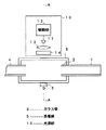
図1は本発明の一実施の形態による煙濃度測定装置の横断面図、図2はその縦断面図である。これらの図に示すように煙濃度測定装置は、試料となる煙、例えばディーゼルエンジン等の排気ガスが加えられるダクト1を有しており、その先端部はノズル2として開放されている。そしてノズル2の外周部を被う透明のガラス管3が設けられ、更にノズル2を通過する煙を吸引するための吸引ダクト4が設けられている。ここでガラス管3は透明で正確な円筒形状を有するものとし、その一部分に反射膜として薄膜が形成されている。この薄膜ミラーは図2に示すように、ガラス管の中心に対して対称に全周の夫々の1/4の範囲に、夫々薄膜ミラー5A,5Bが形成される。これらの薄膜ミラー5はガラス管3の外周から一定の幅Dの範囲で帯状に形成するものとする。尚、吸引ダクト4は大気に直接放出する場合はなくてもよい。
【0010】
さてこのガラス管3の側方には図1,2に示すように光源部10が設けられる。光源部10は例えばレーザダイオード11及びこのレーザダイオード11を駆動する駆動部12を有している。そしてこのレーザ光を平行なレーザ光とするためのコリメートレンズ13及びガラス管3に近接してシリンドリカルレンズ14が設けられる。シリンドリカルレンズ14は図2の円筒軸に垂直(紙面に平行)な面内でのみ集束させ、ガラス管3の中心軸から最短点で焦点を結ぶようにする。こうすればガラス管3の薄膜ミラー5で後述するように繰り返して反射し、ガラス管より出射される。そしてガラス管3から出射されたビームはレンズ15によって受光部に伝達される。
【0011】
受光部は出射光を集束する集束レンズ15、及び集束されたレーザ光を受光して電気信号に変換する光電変換器、例えばフォトダイオード16を有している。フォトダイオード16の出力は増幅器17を介してラッチ部18及び割算器19に与えられる。ラッチ部18は増幅出力を保持するサンプルホールド回路であり、その出力は割算器19に与えられる。割算器19はこれらの入力の割算を行い、その出力を濃度演算部20に与える。濃度演算部20はこの割算出力に基づいてテーブルから濃度を算出するものである。又偏差設定部21は光源部10を図2で上下方向に移動させ、後述する偏差dX を任意の値に設定するものである。
【0012】
次に本実施の形態の動作について説明する。まず駆動部12よりレーザダイオード11を駆動し、レーザ光を発光させる。そしてコリメートレンズ13,シリンドリカルレンズ14により円筒曲率に対して充分細い径を有するレーザビームをガラス管3内の測定領域に照射する。このときダクト1には煙を導かないものとする。こうすれば測定領域にレーザ光が通過しても煙や粉塵によっては減衰することはない。ここでレーザ光は一点鎖線で示すガラス管3の中心点よりわずかに下方に、中心点に最も近い点で所定の偏差dx を持って集束するように薄膜ミラー5Bに向けて照射する。こうすれば中心点から同一距離で焦点を結ぶこととなり、ガラス管3のほぼ対称な位置に入射する。この点から再び反射し、中心点から同一の点データ再び焦点を結んで反射する。こうして徐々に反射位置を変えて同様の動作が繰り返される。又紙面に垂直方向にはガラス管の曲率は影響しないので、光ビームは中心軸を中心として集束位置を変化させて図示のように反射が繰り返される。
【0013】
ここでガラス管3の直径3aと入射レーザ光との偏差をdX とする。ここでガラス管3の外径の半径をr1 、ノズル2の半径をr2 とすると、光ビームの1回の測定光路長dM 及び反射角θは次式で示される。
dM =2×√(r2 2 −dX 2 )
θ= sin-1(dX /r1 )
そして偏差dX を変化させることによって反射回数を任意に選択することができる。測定領域に光が通過するときの通過回数Nは反射回数+1であり、次式で示される。
N=INT{(π/2−θ)/4θ}×2+1
又光の全光路長Lは次式で示される。
L=N・dM
【0014】
このようにすれば反射を繰り返してもガラス管内部の光ビームは徐々に広がることがなく、反射回数を実用上20回以上とすることができる。例えばガラス管の外径r1 を79mmとし、偏差dX を1.6mmとすれば、図3に示すようにミラーの薄膜ミラー5A,5Bによって19回反射して下方の薄膜ミラー5Bより上方に反射される。この反射光は測定領域を20回通過したこととなり、この光をフォトダイオード16によって受光し、反射光のレベルを増幅してラッチ部17に保持しておく。
【0015】
ここで受光レベルは次式で示される。
I=I0 exp(Lβ)
Lは全光路長であり、βは粒子濃度に比例する関数である。I0 は入射光強度である。
【0016】
次いでダクト1に試料となる煙を導入して吸引ダクト4側より吸引し、測定領域を通過させる。この状態で同様にしてレーザ光を測定領域に照射する。こうすれば測定領域をレーザ光が20回通過することとなって煙濃度に応じてレーザ光が減衰するため、この減衰の程度を測定することにより煙濃度が算出できる。この測定領域を粉塵等の煙が通過しているものとすれば、このレーザ光は粉塵の濃度に応じて減衰することとなる。即ちラッチ部18に保持されていた煙を通過させない状態でのレーザ光の強度との比を割算器19によって算出する。割算を行うことによってレーザ光の強度I0 の影響が除かれ、煙の濃度を算出することができる。又光路長Lは一定であるため割算出力からβを算出することができる。割算値に対して粒子濃度をあらかじめ濃度演算部でテーブルとして保持しておいてその値を出力するようにしてもよく、又この関数から濃度を直接算出するようにしてもよい。
【0017】
ここで本実施の形態では入射光をガラス管3の水平な直径3aより偏差dX (ここでは1.6mm)だけ中心より偏差を有するレーザ光としているが、偏差dX の値を変化させることによって入射角θが変化し、この入射角θの変化により通過回数Nが変化することとなる。又全光路長Lも変化する。入射光の偏差dX を適宜変更すれば、全光路長Lを大幅に変化させることができる。従って偏差設定部20によって煙の濃度に対応した偏差dX を設定することによって、全光路長を適宜選択することができ、それによって正確な濃度の測定をすることが可能となる。特に低濃度の場合には全光路長Lを大きくすることによって高精度で濃度測定を行うことができる。
【0018】
尚本実施の形態は図2に示すようにガラス管3の中心を点対称とする2か所に夫々全周の1/4の薄膜ミラーを形成しているが、1/4の範囲に限らず、ガラス管の中心を点対称とした薄膜ミラーを形成するのみで足りる。従って更に多くの範囲又は少ない範囲に薄膜ミラーを形成してもよい。又実際に光が入射し反射する部分にのみ薄膜ミラーを断続的に形成するようにしてもよい。
【0019】
【発明の効果】
以上詳細に説明したように本発明によれば、シリンドリカルレンズを用いることによって多重反射して煙が通過する測定領域で測定光路長を増加させることができる。従って感度が上がり煙濃度が低濃度の場合にも高精度で測定することが可能となる。又正確な形状のガラス管を用いることによって、正確に反射膜が形成できる。従って従来例の煙濃度測定装置に比べて反射回数を大幅に増加させることができ、高感度で測定することができる。更に反射回数を適宜変更することによって、1つの測定装置で低濃度から高濃度までの煙濃度を高精度で測定することができるという効果が得られる。
【図面の簡単な説明】
【図1】本発明の一実施の形態による煙濃度測定装置の横断面図である。
【図2】本発明の一実施の形態による煙濃度測定装置の光軸部分の縦断面図である。
【図3】ガラス管での多重反射の状態を示す図である。
【符号の説明】
1 ダクト
2 ノズル
3 ガラス管
4 吸引ダクト
5,5A,5B 薄膜ミラー
10 光源部
11 レーザダイオード
12 駆動部
13 コリメートレンズ
14 シリンドリカルレンズ
15 集束レンズ
16 フォトダイオード
18 ラッチ部
19 割算器
20 濃度演算部
21 偏差設定部[0001]
BACKGROUND OF THE INVENTION
The present invention relates to a smoke concentration measuring apparatus using a light transmission method.
[0002]
[Prior art]
2. Description of the Related Art Conventionally, a light transmission type smoke concentration measuring device (smoke meter) is known for measuring the concentration of particulate matter discharged from a combustion engine or airborne particulate matter. A conventional light transmission smoke density measuring device is arranged with the light source and light receiving part facing each other, the light path from the light source to the light receiving part intersects with the smoke passage, and the smoke density in the light path is measured from the attenuation rate of the transmitted light To do. In such a light transmission type measuring device, the smoke concentration is measured from the attenuation rate of light that has passed through the sample smoke only once, so the intersection (measurement region) between the light path and the sample smoke path. There was a fault that the sensitivity to low concentration was low. If an attempt is made to enlarge the measurement area in order to eliminate this drawback, the apparatus will be enlarged. In addition, since the crossing portion is small, there is a disadvantage that the temporal variation of the temperature and density of the smoke is large and the output value of the measuring device is not stable.
[0003]
In addition, in the Japanese Patent Application Laid-Open No. 8-43305, the present inventor performs vapor deposition on the circumference of a cylindrical glass tube, and slightly displaces it from the central axis so as to be perpendicular to the central axis from the side of the cylindrical glass tube. A smoke density measuring device has been proposed in which a smoke density is measured by irradiating parallel laser light and reflecting the laser beam multiple times in the measurement region. The number of reflections at this cylindrical glass tube is a function of the distance of the closest point of laser light from the center of the cylindrical glass tube. According to this apparatus, the optical path length becomes long and the smoke density can be measured with high sensitivity.
[0004]
[Problems to be solved by the invention]
In such a conventional apparatus, if the ideal thin parallel light can be irradiated toward the glass tube, the light can be transmitted through the measurement region any number of times. However, since the incident light actually has a certain beam width, the distance from each part to the center of the cylindrical axis is different from the cylindrical axis side to the outer part of the glass tube of the beam. Accordingly, as the number of reflections increases, the reflection point on the mirror shifts due to the laser beam portion, and light with different numbers of reflections eventually overlaps and enters the light receiving unit. For this reason, light with a short optical path length with a small number of reflections is also received at the same time, causing a problem that sensitivity is lowered. Therefore, the practical number of reflections was about seven.
[0005]
The present invention has been made in view of such a conventional problem, and provides a smoke density measuring device capable of measuring the density of smoke with high sensitivity and low density by increasing the number of reflections. The purpose is to do.
[0006]
[Means for Solving the Problems]
The invention of
[0007]
The invention according to
[0008]
According to the present invention having such a feature, the reflection film is formed symmetrically with respect to the central axis of the cylindrical glass tube, and smoke to be measured is introduced into the glass tube. Light is incident from the side of the glass tube from the light source. The incident light does not pass through the center of the glass tube only in a plane perpendicular to the cylindrical axis by the cylindrical lens, but is converged at a point closest to the center and incident on the reflection film. Then, multiple reflections are made by the reflective film a number of times corresponding to the deviation from the center point, and light is attenuated according to the concentration of smoke passing through the glass tube. The light receiving unit receives the reflected light and calculates the density of smoke passing through the glass tube based on the received light level.
[0009]
DETAILED DESCRIPTION OF THE INVENTION
FIG. 1 is a transverse sectional view of a smoke concentration measuring apparatus according to an embodiment of the present invention, and FIG. 2 is a longitudinal sectional view thereof. As shown in these drawings, the smoke concentration measuring apparatus has a
[0010]
As shown in FIGS. 1 and 2, a
[0011]
The light receiving unit includes a focusing lens 15 that focuses the emitted light, and a photoelectric converter, for example, a photodiode 16, that receives the focused laser light and converts it into an electrical signal. The output of the photodiode 16 is supplied to a
[0012]
Next, the operation of the present embodiment will be described. First, the laser diode 11 is driven by the drive unit 12 to emit laser light. The collimating lens 13 and the
[0013]
Here, the deviation between the diameter 3a of the
d M = 2 × √ (r 2 2 −d X 2 )
θ = sin −1 (d X / r 1 )
And it can be arbitrarily selected number of reflections by varying the deviation d X. The number of passes N when light passes through the measurement region is the number of reflections + 1, and is expressed by the following equation.
N = INT {(π / 2−θ) / 4θ} × 2 + 1
The total optical path length L of light is expressed by the following equation.
L = N · d M
[0014]
In this way, even if reflection is repeated, the light beam inside the glass tube does not gradually spread, and the number of reflections can be practically 20 or more. For example, if the outer diameter r 1 of the glass tube is 79 mm and the deviation d X is 1.6 mm, as shown in FIG. 3, it is reflected 19 times by the thin film mirrors 5A and 5B of the mirror and is above the lower thin film mirror 5B. Reflected. This reflected light has passed through the
[0015]
Here, the received light level is expressed by the following equation.
I = I 0 exp (Lβ)
L is the total optical path length and β is a function proportional to the particle concentration. I 0 is the incident light intensity.
[0016]
Next, smoke as a sample is introduced into the
[0017]
Here, in the present embodiment, the incident light is laser light having a deviation dX (1.6 mm in this case) from the horizontal diameter 3a of the
[0018]
In the present embodiment, as shown in FIG. 2, 1/4 thin film mirrors are formed in two places where the center of the
[0019]
【The invention's effect】
As described above in detail, according to the present invention, the measurement optical path length can be increased in the measurement region through which smoke passes through multiple reflections by using the cylindrical lens. Therefore, the sensitivity is increased and measurement can be performed with high accuracy even when the smoke density is low. Further, by using an accurately shaped glass tube, a reflective film can be formed accurately. Therefore, the number of reflections can be significantly increased as compared with the conventional smoke density measuring apparatus, and measurement can be performed with high sensitivity. Further, by appropriately changing the number of reflections, an effect is obtained that the smoke density from a low density to a high density can be measured with high accuracy by one measuring device.
[Brief description of the drawings]
FIG. 1 is a cross-sectional view of a smoke concentration measuring apparatus according to an embodiment of the present invention.
FIG. 2 is a longitudinal sectional view of an optical axis portion of a smoke concentration measuring device according to an embodiment of the present invention.
FIG. 3 is a diagram showing a state of multiple reflection on a glass tube.
[Explanation of symbols]
DESCRIPTION OF
Claims (2)
前記ガラス管の中心軸に垂直な入射光軸を有し、前記ガラス管の中心軸上の点を通過しない光を前記ガラス管の側方から反射膜に向けてレーザ光を入射する光源部と、
前記光源部より入射され、前記ガラス管の反射膜を多重反射した反射光を受光する受光部と、を具備し、
前記光源部は、光源からの光を前記ガラス管の中心軸に垂直な面内で集束し、該光軸上の集束点を、入射光及び全反射光を含む面内で入射光軸に平行な前記ガラス管の直径の中心点より所定の偏差を有する位置とするシリンドリカルレンズを具備することを特徴とする煙濃度測定装置。A cylindrical glass tube in which a reflection film is formed at a position symmetrical with respect to the central axis of the outer peripheral surface, and smoke to be measured is introduced;
A light source unit that has an incident optical axis perpendicular to the central axis of the glass tube, and that emits laser light from a side of the glass tube toward a reflection film that does not pass through a point on the central axis of the glass tube; ,
A light receiving unit that receives the reflected light incident from the light source unit and multiple-reflected on the reflective film of the glass tube,
The light source unit focuses light from the light source in a plane perpendicular to the central axis of the glass tube, and a focusing point on the optical axis is parallel to the incident optical axis in a plane including incident light and total reflected light. A smoke concentration measuring apparatus comprising a cylindrical lens having a predetermined deviation from a center point of the diameter of the glass tube.
Priority Applications (1)
| Application Number | Priority Date | Filing Date | Title |
|---|---|---|---|
| JP2001236681A JP3638261B2 (en) | 2001-08-03 | 2001-08-03 | Smoke density measuring device |
Applications Claiming Priority (1)
| Application Number | Priority Date | Filing Date | Title |
|---|---|---|---|
| JP2001236681A JP3638261B2 (en) | 2001-08-03 | 2001-08-03 | Smoke density measuring device |
Publications (2)
| Publication Number | Publication Date |
|---|---|
| JP2003050202A JP2003050202A (en) | 2003-02-21 |
| JP3638261B2 true JP3638261B2 (en) | 2005-04-13 |
Family
ID=19067904
Family Applications (1)
| Application Number | Title | Priority Date | Filing Date |
|---|---|---|---|
| JP2001236681A Expired - Fee Related JP3638261B2 (en) | 2001-08-03 | 2001-08-03 | Smoke density measuring device |
Country Status (1)
| Country | Link |
|---|---|
| JP (1) | JP3638261B2 (en) |
Cited By (1)
| Publication number | Priority date | Publication date | Assignee | Title |
|---|---|---|---|---|
| US11506586B2 (en) | 2020-08-17 | 2022-11-22 | Carrier Corporation | Photoelectric smoke sensor tube |
Families Citing this family (2)
| Publication number | Priority date | Publication date | Assignee | Title |
|---|---|---|---|---|
| EP1695066A4 (en) * | 2003-12-12 | 2010-02-17 | Elt Inc | Gas sensor |
| FI129342B (en) | 2015-11-11 | 2021-12-15 | Teknologian Tutkimuskeskus Vtt Oy | Low volume multipass cell |
-
2001
- 2001-08-03 JP JP2001236681A patent/JP3638261B2/en not_active Expired - Fee Related
Cited By (1)
| Publication number | Priority date | Publication date | Assignee | Title |
|---|---|---|---|---|
| US11506586B2 (en) | 2020-08-17 | 2022-11-22 | Carrier Corporation | Photoelectric smoke sensor tube |
Also Published As
| Publication number | Publication date |
|---|---|
| JP2003050202A (en) | 2003-02-21 |
Similar Documents
| Publication | Publication Date | Title |
|---|---|---|
| JP2021004888A (en) | Two-dimensional scan type high accuracy lidar using combination of rotary concave mirror and beam steering device | |
| JP2007256281A (en) | Gas sensor | |
| JPH0954278A (en) | Optical device for controlling expanding angle of annular light ray | |
| US20050259261A1 (en) | Sample analyzer | |
| JPH04504908A (en) | Light emitter/receiver | |
| JP2005195588A (en) | Method and device for measuring light absorption or light scattering of biological element | |
| CN109358435B (en) | Device and method for adjusting perpendicularity of double telecentric lenses | |
| JP2012255738A (en) | Optical measuring apparatus | |
| JP5252892B2 (en) | Optical unit | |
| JP3638261B2 (en) | Smoke density measuring device | |
| JP2012242245A (en) | Raman scattering light detection device | |
| JPH0843305A (en) | Smoke density measuring device | |
| JP2001272259A (en) | Flowmeter | |
| JP2009282073A (en) | Intensity modulation method for terahertz wave and intensity modulator for terahertz wave | |
| JP2010091428A (en) | Scanning optical system | |
| JP4029406B2 (en) | Optical analyzer | |
| JP2003164415A (en) | Method and apparatus for obtaining fluorescence spectrum | |
| JP2920122B2 (en) | In-pipe inspection method and in-pipe inspection apparatus | |
| JP7483016B2 (en) | Distance measuring device | |
| JP2006508368A (en) | Optical hydrophone for measuring sound pressure distribution in liquid media | |
| KR102116618B1 (en) | Inspection apparatus for surface of optic specimen and controlling method thereof | |
| CN217162084U (en) | Intraoral image scanner and laser scanning device thereof | |
| WO2022201406A1 (en) | Optical device and method for controlling optical device | |
| CN114062315B (en) | Tunable semiconductor laser absorption spectrum system | |
| WO2022044317A1 (en) | Distance measurement device |
Legal Events
| Date | Code | Title | Description |
|---|---|---|---|
| A131 | Notification of reasons for refusal |
Free format text: JAPANESE INTERMEDIATE CODE: A131 Effective date: 20040824 |
|
| A521 | Written amendment |
Free format text: JAPANESE INTERMEDIATE CODE: A523 Effective date: 20041012 |
|
| TRDD | Decision of grant or rejection written | ||
| A01 | Written decision to grant a patent or to grant a registration (utility model) |
Free format text: JAPANESE INTERMEDIATE CODE: A01 Effective date: 20050105 |
|
| A61 | First payment of annual fees (during grant procedure) |
Free format text: JAPANESE INTERMEDIATE CODE: A61 Effective date: 20050107 |
|
| R150 | Certificate of patent or registration of utility model |
Free format text: JAPANESE INTERMEDIATE CODE: R150 |
|
| LAPS | Cancellation because of no payment of annual fees |