JP3629054B2 - Surface correction coating method for welded can side seam - Google Patents
Surface correction coating method for welded can side seam Download PDFInfo
- Publication number
- JP3629054B2 JP3629054B2 JP31981394A JP31981394A JP3629054B2 JP 3629054 B2 JP3629054 B2 JP 3629054B2 JP 31981394 A JP31981394 A JP 31981394A JP 31981394 A JP31981394 A JP 31981394A JP 3629054 B2 JP3629054 B2 JP 3629054B2
- Authority
- JP
- Japan
- Prior art keywords
- paint
- correction
- side seam
- air
- welded
- Prior art date
- Legal status (The legal status is an assumption and is not a legal conclusion. Google has not performed a legal analysis and makes no representation as to the accuracy of the status listed.)
- Expired - Fee Related
Links
Images


Landscapes
- Details Of Rigid Or Semi-Rigid Containers (AREA)
- Application Of Or Painting With Fluid Materials (AREA)
- Ink Jet (AREA)
Description
【0001】
【産業上の利用分野】
本発明は、飲料缶等に用いられる溶接缶のサイドシームの外面を塗装により補正する方法に関する。
【0002】
【従来の技術】
清涼飲料等の包装用缶としては近年溶接缶が多く用いられているが、溶接缶の接合部であるサイドシームには金属露出部があり、防錆、防食、美観等の点から塗料を塗布して補正することが行われている。一方、前記サイドシームの溶接部には段差があるため一般の塗装では金属露出部が残存することがあり、この部分から錆が発生して美観が損なわれる等の問題が生じる。そのため、塗料を多めにして補正することが行われているが、通常前記サイドシームを上面にして前記缶胴を搬送しているので、塗料が前記缶胴の周方向のサイドシーム以外の箇所に流出して塗料が無駄になるという不都合がある。
【0003】
また、通常缶体の製造業者は、缶体に起因する何らかの不具合が発生したときにその原因の究明や製品の回収等をするために、缶体の製造年月日や製造ライン等のコードマークを缶体に表示している。例えば、従来例として特開平6−156503号公報においてコードマークをサイドシームの金属露出面に印刷することが提案されている。しかし、金属露出面にコードマークを印刷し、その後にサイドシームの補正を行うとコードマークのインクの上に補正塗料を塗布することになり塗料とサイドシームの密着が悪くなるため、レトルト殺菌やその後の冷却等の過酷な熱履歴によっては補正塗料が剥離してこの剥離した箇所から錆が発生するという不都合がある。
【0004】
【発明が解決しようとする課題】
本発明は、溶接缶のサイドシームの外面の補正塗装方法の改良を目的とし、更に詳しくは補正塗料が少なくても確実に補正ができ、サイドシーム部にコードマークを印刷しても補正した塗料が剥離しないサイドシームの外面補正塗装方法を提供することを目的とする。
【0005】
【課題を解決するための手段】
前記目的を達成するために、本発明の溶接缶サイドシームの外面補正塗装方法は、缶胴ブランクを溶接して缶胴を形成し、前記缶胴を軸方向に搬送しながら前記缶胴の溶接部外面に補正塗料を塗布する溶接缶サイドシームの外面補正塗装方法において、前記缶胴を搬送する途中で前記補正塗料を塗布した後、前記缶胴の搬送の上流で前記缶胴の周方向の一方から空気を吐出した後に下流で前記上流とは反対方向から空気を吐出することにより前記缶胴の周方向の両側から前記塗布された塗料に空気を吐出し、前記補正塗料が前記缶胴の周方向へ流出することを防止して前記補正塗料を乾燥させることを特徴とする。
【0007】
また、前記補正塗料の乾燥の後、前記サイドシームの塗装面に前記缶胴の製造に関するコードマークを印刷してもよい。
【0008】
【作用】
本発明の溶接缶サイドシームの外面補正塗装方法によれば、前記補正塗料を塗布した後に前記缶胴の周方向の両側から前記塗布された塗料に空気を吐出するので、前記補正塗料が吐出された空気により中央方向に押されるのでサイドシームから塗料が周方向に流出しない。
【0009】
また、前記補正塗料の乾燥を前記缶胴の搬送の上流で一方から空気を吐出した後に下流で前記上流とは反対方向から空気を吐出することにより行うため、上流と下流で吐出された空気が互いに干渉しない。
【0010】
また、前記補正塗料の乾燥の後、前記サイドシームの塗装面に前記缶胴の製造に関するコードマークを印刷したときは、補正塗料と金属部分の間にコードマークのインクを介することなく金属露出部分に補正塗料が直接塗布される。
【0011】
【実施例】
次に、添付の図面を参照しながら本発明の溶接缶サイドシームの外面補正塗装方法の実施例について説明する。図1は本実施例における補正塗料の塗布及びその乾燥の状態を示す説明的平面図、図2は図1のII−II断面図、図3は図1のIII−III断面図、図4は図1のIV−IV断面図、図5は図1のV−V断面図である。
【0012】
先ず、本実施例における各部の構成について説明する。本実施例では、缶胴1は溶接缶であり、この缶胴1のサイドシーム2に補正塗料4を塗布するアウトサイドシームストライプガン(以下OSSガンと省略する)3を缶胴1の搬送路上に配設し、このOSSガン3から約10cmの距離をおいて缶胴1の進行方向の下流に缶胴1の周方向の一方から空気6を吐出する第1エアノズル5を配設し、その下流に第1エアノズル5とは反対方向から空気8を吐出する第2エアノズル7を配設し、その下流にインク10を吐出して缶胴1の製造履歴等を表示するコードマーク印刷するインクジェットプリンタヘッド9を配設している。
【0013】
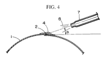
缶胴1は錫めっき鋼板又は錫ニッケルめっき鋼板製で、サイドシーム2以外の外面は内容物を表示するための印刷が施されており、サイドシーム2は金属面が露出している。塗料4には一般にエポキシ樹脂系塗料が多く用いられており、本実施例ではエポキシ・尿素系樹脂を用いている。その粘度はNo.4フォードカップ、25°Cで15秒であり、加熱残分はサンプル1.0g当たり160°C−30分で20%であり、比重は20°Cで0.936であり、乾燥塗膜量は40〜60mg/100cm2 である。第1エアノズル5及び第2エアノズル7は、図1に示すように缶胴1の進行方向に向かって幅広く形成し、0.1Kg/cm2 の圧力で空気6,8を吐出している。また、空気6,8を図3及び図4に示すように水平方向に角度αをつけて吐出しており、本実施例では20°である。角度αはあまり角度をつけすぎると塗料4が逆に周方向に流出してしまい、あまり角度をつけないと塗料4を押しながらその表面を乾燥するのに適さないため、10°〜30°が好ましい。また、第1エアノズル5及び第2エアノズル7を缶胴1の進行方向に互いにオフセットして配設し空気6と空気8が互いに干渉しないようにしている。また、本実施例では空気6,8にホットエアを用いている。
【0014】
また、インクジェットプリンタヘッド9は、その先端をサイドシーム2が通過する軌道の約10mm上方に配設し、サイドシーム2の表面に塗装された塗料4の表面にインク10を吐出できるようにしている。インク10はメチルエチルケトン,メタノール,樹脂及び染料からなるものを使用している。
【0015】
次に、本実施例の方法について説明する。先ず、図示しない溶接装置により溶接された缶胴1は、図示しない搬送装置により図1の矢印の示す方向に搬送される。次に、OSSガン3により塗料4をサイドシーム2の外面に吐出し、金属露出面を全て塗料4で覆う。このとき、塗料4は上述の如く加熱残分が20%であり80%が溶剤なので、図2に示すように缶胴1の周方向に流動して集まっておりその表面は乾燥していない。
【0016】
次に第1エアノズル5により空気6を吐出する。この空気6により塗料4は図3に示すように第1エアノズル5の反対側に押され、同時に第1エアノズル5側の塗料は塗料4の境界線から徐々に乾燥していく。また、本実施例では、図3に示すようにサイドシームの溶接部の缶胴ブランクの端部が外側に重なっている方向から空気6を吐出するようにしている。これは、この反対方向から先に空気を吐出するとサイドシーム2の溶接部の段差の角部2aの塗料が薄くなってしまうおそれがあるためである。
【0017】
次に第2エアノズル7により第1エアノズル5とは反対側から空気8を吐出する。この空気8により塗料4は図4に示すように第2エアノズル7とは反対側に押されるが、第1エアノズル5側の塗料4は乾燥途中なのでサイドシーム2の周方向の中心付近に塗料4が集まり、塗料4の全体が乾燥していく。塗料4の全体が乾燥すると、図5に示すようにサイドシーム2の周方向の中心付近がやや厚めに塗装されるので、サイドシーム2の溶接部の段差は塗料4によって十分に被覆される。
【0018】
次に、図5に示すように、インクジェットプリンタヘッド9によりインク10を吐出して缶胴1の製造履歴を表示するコードマークを乾燥した塗料4の表面に印刷する。このように、コードマークを補正塗装の後に行っているので、塗料4は表面が金属であるサイドシーム2に直接塗布されてサイドシーム2との密着が良くなり、その後のレトルト処理等の過酷な熱履歴によっても塗料4が剥がれることがない。また、本実施例で用いたインク10で印刷するときは塗料4の残留溶剤が約30%以下でないとインク10が塗料4中に拡散してコードマークが不鮮明になる。従って、第2エアノズル7からインクジェットプリンタヘッド9までの距離は塗料4の乾燥速度や搬送速度或いは吐出する空気6,8の温度等を考慮して定める。本実施例では塗料4を塗布した後、第1及び第2エアノズル5,7により空気6,8を吐出して塗料4を乾燥しており、更に空気6,8にはホットエアを用いているので塗料4の乾燥が迅速に行われるため、サイドシームの補正塗装設備にインクジェットプリンタヘッド9を設けることができる。
【0019】
【発明の効果】
本発明の溶接缶サイドシームの外面補正塗装方法によれば、補正塗料をサイドシームの補正に必要な量だけ吐出するため塗料がが周方向に流出しないので、塗料の使用量を低減することができる。
【0020】
前記補正塗料の乾燥を前記缶胴の搬送の上流で一方から空気を吐出した後に下流で前記上流とは反対方向から空気を吐出することにより行っているため、上流と下流で吐出された空気が互いに干渉しないので、周方向の両側から同時に空気を吐出したときのように気流が乱れて塗装表面が乱れることがない。
【0021】
また、前記補正塗料の乾燥の後、前記サイドシームの塗装面に前記缶胴の製造に関するコードマークを印刷したときは、補正塗料と金属部分の間にコードマークのインクを介することなく金属露出部分に補正塗料が直接塗布されるので、補正塗料とサイドシームの密着がよく、その後にレトルト処理等の過酷な熱履歴によっても補正塗料が剥離しない。
【図面の簡単な説明】
【図1】本発明の一実施例における補正塗料の塗布及びその乾燥の状態を示す説明的平面図。
【図2】図1のII−II断面図。
【図3】図1のIII−III断面図。
【図4】図1のIV−IV断面図。
【図5】図1のV−V断面図。
【符号の説明】
1…缶胴、2…サイドシーム、3…OSSガン、4…塗料、5…第1エアノズル、6…空気、7…第2エアノズル、8…空気、9…インクジェットプリンタヘッド、10…インク。[0001]
[Industrial application fields]
The present invention relates to a method for correcting an outer surface of a side seam of a welding can used for a beverage can or the like by painting.
[0002]
[Prior art]
In recent years, welded cans are often used as packaging cans for soft drinks, etc., but the side seams that are welded joints have exposed metal parts, and paints are applied to prevent rust, corrosion, and beauty. It has been corrected. On the other hand, since there is a step in the welded portion of the side seam, a metal exposed portion may remain in general coating, and problems such as rusting from this portion and loss of aesthetics arise. Therefore, correction is made with a larger amount of paint, but since the can body is usually transported with the side seam as the upper surface, the paint is placed in a place other than the side seam in the circumferential direction of the can body. There is an inconvenience that the paint flows out and is wasted.
[0003]
In addition, when a manufacturer of a can body usually finds out the cause of a malfunction caused by the can body and collects the product, the code mark of the production date of the can body, the production line, etc. Is displayed on the can body. For example, as a conventional example, Japanese Patent Laid-Open No. 6-156503 proposes printing a code mark on a metal exposed surface of a side seam. However, if the code mark is printed on the exposed metal surface and then the side seam correction is performed, the correction paint is applied on the ink of the code mark, resulting in poor adhesion between the paint and the side seam. Depending on a severe heat history such as subsequent cooling, there is a disadvantage that the correction paint is peeled off and rust is generated from the peeled off part.
[0004]
[Problems to be solved by the invention]
The present invention aims to improve the correction coating method for the outer surface of the side seam of a welding can. More specifically, the correction can be surely performed even if the correction coating is small, and the coating is corrected even if a code mark is printed on the side seam. An object of the present invention is to provide a side seam outer surface correction coating method that does not peel off.
[0005]
[Means for Solving the Problems]
In order to achieve the above object, according to the outer surface correction coating method of a welded can side seam of the present invention, a can body blank is welded to form a can body, and the can body is welded while transporting the can body in the axial direction. In the outer surface correction coating method of a welded can side seam in which a correction paint is applied to the outer surface of the part, after the correction paint is applied in the course of transporting the can body, the circumferential direction of the can body is upstream of the transport of the can body. After discharging air from one side, air is discharged from both sides in the circumferential direction of the can body by discharging air from the opposite direction to the upstream downstream, and the correction paint is applied to the can body The correction coating material is dried by preventing it from flowing out in the circumferential direction.
[0007]
Further, after the correction paint is dried, a code mark relating to the manufacture of the can body may be printed on the painted surface of the side seam.
[0008]
[Action]
According to the outer surface correction coating method of the welded can side seam of the present invention, after applying the correction paint, air is discharged from both sides in the circumferential direction of the can body to the applied paint, so that the correction paint is discharged. Since the air is pushed toward the center, the paint does not flow out from the side seam in the circumferential direction.
[0009]
Further, the correction paint line by drying and the can body upstream in the upstream downstream after discharging the air from one of the transport of the discharged air from the opposite direction of Utame, air discharged by the upstream and downstream Do not interfere with each other.
[0010]
In addition, when the code mark relating to the manufacture of the can body is printed on the painted surface of the side seam after the correction paint is dried, the exposed metal portion without the code mark ink between the correction paint and the metal portion. The corrective paint is applied directly to.
[0011]
【Example】
Next, an embodiment of the outer surface correction coating method for welded can side seams according to the present invention will be described with reference to the accompanying drawings. FIG. 1 is an explanatory plan view showing the state of application of a correction paint and its drying state in this embodiment, FIG. 2 is a sectional view taken along line II-II in FIG. 1, FIG. 3 is a sectional view taken along line III-III in FIG. 1 is a sectional view taken along the line IV-IV in FIG. 1, and FIG. 5 is a sectional view taken along the line V-V in FIG.
[0012]
First, the structure of each part in a present Example is demonstrated. In this embodiment, the can body 1 is a welded can, and an outside seam stripe gun (hereinafter abbreviated as OSS gun) 3 for applying the
[0013]
The can body 1 is made of a tin-plated steel plate or a tin-nickel plated steel plate, and the outer surface other than the
[0014]
Further, the
[0015]
Next, the method of the present embodiment will be described. First, the can body 1 welded by a welding device (not shown) is transported in a direction indicated by an arrow in FIG. 1 by a transport device (not shown). Next, the
[0016]
Next,
[0017]
Next,
[0018]
Next, as shown in FIG. 5, the
[0019]
【The invention's effect】
According to the outer surface correction coating method for a welded can side seam of the present invention, since the coating material is discharged in an amount necessary for correcting the side seam, the coating material does not flow out in the circumferential direction. it can.
[0020]
Because doing by discharging air from the opposite direction to the upstream downstream after discharging the air from one drying of the correction paint upstream of the conveyance of the can body, the air discharged by the upstream and downstream Since they do not interfere with each other, the air flow is disturbed and the coating surface is not disturbed as when air is simultaneously discharged from both sides in the circumferential direction.
[0021]
In addition, when the code mark relating to the manufacture of the can body is printed on the painted surface of the side seam after the correction paint is dried, the exposed metal portion without the code mark ink between the correction paint and the metal portion. Since the correction coating is directly applied to the surface, the correction coating and the side seam are in close contact with each other, and the correction coating is not peeled off even by a severe heat history such as a retort treatment.
[Brief description of the drawings]
FIG. 1 is an explanatory plan view showing a state of application of a correction paint and its drying state in one embodiment of the present invention.
2 is a cross-sectional view taken along the line II-II in FIG.
3 is a cross-sectional view taken along the line III-III in FIG.
4 is a cross-sectional view taken along the line IV-IV in FIG.
5 is a cross-sectional view taken along the line VV in FIG.
[Explanation of symbols]
DESCRIPTION OF SYMBOLS 1 ... Can body, 2 ... Side seam, 3 ... OSS gun, 4 ... Paint, 5 ... 1st air nozzle, 6 ... Air, 7 ... 2nd air nozzle, 8 ... Air, 9 ... Inkjet printer head, 10 ... Ink.
Claims (2)
前記缶胴を搬送する途中で前記補正塗料を塗布した後、前記缶胴の搬送の上流で前記缶胴の周方向の一方から空気を吐出した後に下流で前記上流とは反対方向から空気を吐出することにより前記缶胴の周方向の両側から前記塗布された塗料に空気を吐出し、
前記補正塗料が前記缶胴の周方向へ流出することを防止して前記補正塗料を乾燥させることを特徴とする溶接缶サイドシームの外面補正塗装方法。In the outer surface correction coating method of a welded can side seam that forms a can body by welding a can body blank, and applies a correction paint to the outer surface of the welded portion of the can body while conveying the can body in the axial direction.
After applying the correction paint in the middle of transporting the can body, the air is discharged from one of the circumferential directions of the can body upstream of the transport of the can body, and then the air is discharged downstream from the opposite direction to the upstream. By discharging air to the applied paint from both sides in the circumferential direction of the can body,
An outer surface correction coating method for a welding can side seam, wherein the correction coating is prevented from flowing out in a circumferential direction of the can body and the correction coating is dried.
Priority Applications (1)
| Application Number | Priority Date | Filing Date | Title |
|---|---|---|---|
| JP31981394A JP3629054B2 (en) | 1994-12-22 | 1994-12-22 | Surface correction coating method for welded can side seam |
Applications Claiming Priority (1)
| Application Number | Priority Date | Filing Date | Title |
|---|---|---|---|
| JP31981394A JP3629054B2 (en) | 1994-12-22 | 1994-12-22 | Surface correction coating method for welded can side seam |
Publications (2)
| Publication Number | Publication Date |
|---|---|
| JPH08173890A JPH08173890A (en) | 1996-07-09 |
| JP3629054B2 true JP3629054B2 (en) | 2005-03-16 |
Family
ID=18114493
Family Applications (1)
| Application Number | Title | Priority Date | Filing Date |
|---|---|---|---|
| JP31981394A Expired - Fee Related JP3629054B2 (en) | 1994-12-22 | 1994-12-22 | Surface correction coating method for welded can side seam |
Country Status (1)
| Country | Link |
|---|---|
| JP (1) | JP3629054B2 (en) |
Families Citing this family (24)
| Publication number | Priority date | Publication date | Assignee | Title |
|---|---|---|---|---|
| EP2259664B1 (en) | 2004-07-21 | 2017-10-18 | Mevion Medical Systems, Inc. | A programmable radio frequency waveform generator for a synchrocyclotron |
| EP2389981A3 (en) | 2005-11-18 | 2012-03-07 | Still River Systems, Inc. | Charged particle radiation therapy |
| US8003964B2 (en) | 2007-10-11 | 2011-08-23 | Still River Systems Incorporated | Applying a particle beam to a patient |
| US8581523B2 (en) | 2007-11-30 | 2013-11-12 | Mevion Medical Systems, Inc. | Interrupted particle source |
| US8933650B2 (en) | 2007-11-30 | 2015-01-13 | Mevion Medical Systems, Inc. | Matching a resonant frequency of a resonant cavity to a frequency of an input voltage |
| US9622335B2 (en) | 2012-09-28 | 2017-04-11 | Mevion Medical Systems, Inc. | Magnetic field regenerator |
| JP6254600B2 (en) | 2012-09-28 | 2017-12-27 | メビオン・メディカル・システムズ・インコーポレーテッド | Particle accelerator |
| US9681531B2 (en) | 2012-09-28 | 2017-06-13 | Mevion Medical Systems, Inc. | Control system for a particle accelerator |
| US10254739B2 (en) | 2012-09-28 | 2019-04-09 | Mevion Medical Systems, Inc. | Coil positioning system |
| TW201422279A (en) | 2012-09-28 | 2014-06-16 | Mevion Medical Systems Inc | Focusing a particle beam |
| TW201433331A (en) | 2012-09-28 | 2014-09-01 | Mevion Medical Systems Inc | Adjusting coil position |
| CN104812444B (en) | 2012-09-28 | 2017-11-21 | 梅维昂医疗系统股份有限公司 | The energy adjustment of the particle beams |
| TW201438787A (en) | 2012-09-28 | 2014-10-16 | Mevion Medical Systems Inc | Controlling particle therapy |
| US9730308B2 (en) | 2013-06-12 | 2017-08-08 | Mevion Medical Systems, Inc. | Particle accelerator that produces charged particles having variable energies |
| CN110237447B (en) | 2013-09-27 | 2021-11-02 | 梅维昂医疗系统股份有限公司 | Particle therapy system |
| US9962560B2 (en) | 2013-12-20 | 2018-05-08 | Mevion Medical Systems, Inc. | Collimator and energy degrader |
| US10675487B2 (en) | 2013-12-20 | 2020-06-09 | Mevion Medical Systems, Inc. | Energy degrader enabling high-speed energy switching |
| US9661736B2 (en) | 2014-02-20 | 2017-05-23 | Mevion Medical Systems, Inc. | Scanning system for a particle therapy system |
| US9950194B2 (en) | 2014-09-09 | 2018-04-24 | Mevion Medical Systems, Inc. | Patient positioning system |
| US10786689B2 (en) | 2015-11-10 | 2020-09-29 | Mevion Medical Systems, Inc. | Adaptive aperture |
| US10925147B2 (en) | 2016-07-08 | 2021-02-16 | Mevion Medical Systems, Inc. | Treatment planning |
| US11103730B2 (en) | 2017-02-23 | 2021-08-31 | Mevion Medical Systems, Inc. | Automated treatment in particle therapy |
| EP3645111A1 (en) | 2017-06-30 | 2020-05-06 | Mevion Medical Systems, Inc. | Configurable collimator controlled using linear motors |
| WO2020185544A1 (en) | 2019-03-08 | 2020-09-17 | Mevion Medical Systems, Inc. | Delivery of radiation by column and generating a treatment plan therefor |
-
1994
- 1994-12-22 JP JP31981394A patent/JP3629054B2/en not_active Expired - Fee Related
Also Published As
| Publication number | Publication date |
|---|---|
| JPH08173890A (en) | 1996-07-09 |
Similar Documents
| Publication | Publication Date | Title |
|---|---|---|
| JP3629054B2 (en) | Surface correction coating method for welded can side seam | |
| US7927667B2 (en) | Spray apparatus and method for the repair of can ends | |
| EP1057542A3 (en) | Air assisted liquid dispensing apparatus and method for increasing contact area between the liquid and a substrate | |
| EP0638425A2 (en) | Method for modifying phase change ink jet printing heads to prevent degradation of ink contact angles | |
| EP2918421B1 (en) | Method for inkjet printing on moldings | |
| JPH0624659B2 (en) | Can body coating method and coating device | |
| US4743469A (en) | Method of applying adhesive to containers in labeling machines | |
| JP2783318B2 (en) | Method and apparatus for applying inner coating to container body | |
| US6578474B1 (en) | Printing or coating method and printing or coating device | |
| JPH10138461A (en) | Printer | |
| JPS6036849B2 (en) | Manufacturing method for sheet metal containers | |
| EP2810541B1 (en) | Method and arrangement for transferring electrically conductive material in fluid form on a substrate to be printed | |
| JP7171246B2 (en) | Method for manufacturing printed can, and printed can | |
| JPH0491949A (en) | Continuous lamination of printed film to metal coil | |
| JP3760289B2 (en) | Powder nozzle with air entrainment prevention shield plate | |
| JP4083920B2 (en) | Metal can | |
| JP2005262011A (en) | Coating apparatus of high-viscosity material | |
| JP3958894B2 (en) | A method for correcting a resin film on the back surface of a welded washer for attaching a hand ring of a can lid, a can lid with a hand ring corrected using the correction method, and a correcting device. | |
| JPS6271574A (en) | Method for repairing weld zone | |
| JPS61245863A (en) | Method and apparatus for painting inner surface of pipe | |
| EP1182140A1 (en) | Food can end | |
| JP2001180842A (en) | Guide device for flat printing object | |
| KR20010044522A (en) | Method of making a steel design tab for a beverage can | |
| JPH07195013A (en) | Adhesive coater | |
| KR900006553A (en) | Plating method of metal plate |
Legal Events
| Date | Code | Title | Description |
|---|---|---|---|
| A977 | Report on retrieval |
Free format text: JAPANESE INTERMEDIATE CODE: A971007 Effective date: 20040722 |
|
| A131 | Notification of reasons for refusal |
Free format text: JAPANESE INTERMEDIATE CODE: A131 Effective date: 20040803 |
|
| A521 | Written amendment |
Free format text: JAPANESE INTERMEDIATE CODE: A523 Effective date: 20040924 |
|
| TRDD | Decision of grant or rejection written | ||
| A01 | Written decision to grant a patent or to grant a registration (utility model) |
Free format text: JAPANESE INTERMEDIATE CODE: A01 Effective date: 20041207 |
|
| A61 | First payment of annual fees (during grant procedure) |
Free format text: JAPANESE INTERMEDIATE CODE: A61 Effective date: 20041210 |
|
| R150 | Certificate of patent (=grant) or registration of utility model |
Free format text: JAPANESE INTERMEDIATE CODE: R150 |
|
| S111 | Request for change of ownership or part of ownership |
Free format text: JAPANESE INTERMEDIATE CODE: R313111 |
|
| R350 | Written notification of registration of transfer |
Free format text: JAPANESE INTERMEDIATE CODE: R350 |
|
| FPAY | Renewal fee payment (prs date is renewal date of database) |
Free format text: PAYMENT UNTIL: 20081217 Year of fee payment: 4 |
|
| FPAY | Renewal fee payment (prs date is renewal date of database) |
Free format text: PAYMENT UNTIL: 20091217 Year of fee payment: 5 |
|
| FPAY | Renewal fee payment (prs date is renewal date of database) |
Free format text: PAYMENT UNTIL: 20101217 Year of fee payment: 6 |
|
| FPAY | Renewal fee payment (prs date is renewal date of database) |
Free format text: PAYMENT UNTIL: 20101217 Year of fee payment: 6 |
|
| FPAY | Renewal fee payment (prs date is renewal date of database) |
Free format text: PAYMENT UNTIL: 20111217 Year of fee payment: 7 |
|
| FPAY | Renewal fee payment (prs date is renewal date of database) |
Free format text: PAYMENT UNTIL: 20111217 Year of fee payment: 7 |
|
| FPAY | Renewal fee payment (prs date is renewal date of database) |
Free format text: PAYMENT UNTIL: 20121217 Year of fee payment: 8 |
|
| FPAY | Renewal fee payment (prs date is renewal date of database) |
Free format text: PAYMENT UNTIL: 20131217 Year of fee payment: 9 |
|
| LAPS | Cancellation because of no payment of annual fees |