JP3607089B2 - Torque control device for hydraulic pump of hydraulic construction machinery - Google Patents
Torque control device for hydraulic pump of hydraulic construction machinery Download PDFInfo
- Publication number
- JP3607089B2 JP3607089B2 JP24989798A JP24989798A JP3607089B2 JP 3607089 B2 JP3607089 B2 JP 3607089B2 JP 24989798 A JP24989798 A JP 24989798A JP 24989798 A JP24989798 A JP 24989798A JP 3607089 B2 JP3607089 B2 JP 3607089B2
- Authority
- JP
- Japan
- Prior art keywords
- torque
- hydraulic pump
- hydraulic
- prime mover
- construction machine
- Prior art date
- Legal status (The legal status is an assumption and is not a legal conclusion. Google has not performed a legal analysis and makes no representation as to the accuracy of the status listed.)
- Expired - Lifetime
Links
Images
Landscapes
- Operation Control Of Excavators (AREA)
- Control Of Vehicle Engines Or Engines For Specific Uses (AREA)
- Fluid-Pressure Circuits (AREA)
- Control Of Positive-Displacement Pumps (AREA)
Description
【0001】
【発明の属する技術分野】
本発明は油圧建設機械の油圧ポンプのトルク制御装置に係わり、特に原動機としてディーゼルエンジンを備え、このエンジンにより回転駆動される油圧ポンプから吐出される圧油により油圧アクチュエータを駆動し、必要な作業を行う油圧ショベル等の油圧建設機械の油圧ポンプのトルク制御装置に関する。
【0002】
【従来の技術】
油圧ショベル等の油圧建設機械は、一般に、原動機としてディーゼルエンジンを備え、このエンジンにより少なくとも1つの可変容量型の油圧ポンプを回転駆動し、油圧ポンプから吐出される圧油により油圧アクチュエータを駆動し、必要な作業を行っている。このディーゼルエンジンにはアクセルレバー等の目標回転数を指令する入力手段が備えられ、この目標回転数に応じて燃料噴射量が制御され、回転数が制御される。
【0003】
このような油圧建設機械におけるエンジンと油圧ポンプの制御に関して、特公昭62−8618号公報に「内燃機関と液圧ポンプとを含む駆動系の制御方法」と題した制御方法が提案されている。この制御方法は、目標回転数に対して回転数センサからの実エンジン回転数との差(回転数偏差)を求め、この回転数偏差を使って油圧ポンプの入力トルクを制御する、いわゆるスピードセンシング制御の例である。
【0004】
この制御の目的は、目標回転数に対して検出された実エンジン回転数が低下した場合、油圧ポンプの負荷トルク(入力トルク)を低下させ、エンジン停止を防止し、エンジンの出力を有効に利用することである。
【0005】
【発明が解決しようとする課題】
ところで、エンジンの出力低下は、エンジンを取り巻く環境で変わってくる。例えば使用する場所が高地であった場合は、大気圧の低下でエンジン出力トルクは低下する。
【0006】
エンジン負荷が軽いときは、燃料噴射装置(ガバナ機構)のレギュレーション上の点がエンジン負荷と出力トルクのマッチング点となり、環境の変化によるエンジンの出力低下に係わらずエンジン回転数は目標回転数より少し高い、ガバナ機構のレギュレーション特性線上の点となる。
【0007】
エンジン負荷が増加した場合、エンジン固有のエンジン出力トルク特性で決まる目標回転数に対する出力トルクがエンジン負荷とのマッチング点となり、このマッチング点においては、環境の変化によりエンジン出力が低下すると、上記スピードセンシング制御はエンジン回転数の低下に応じて油圧ポンプの吸収トルクを低下させ、油圧ポンプの吸収トルクとエンジンの出力トルクが等しくなった点でマッチングする。
【0008】
このため、上記従来技術では、エンジン負荷の増加時は、環境の変化でエンジン出力が低下すると、エンジン負荷が軽負荷から高負荷になるにつれてエンジン回転数が大きく低下する。例えば油圧建設機械が油圧ショベルであり、この油圧ショベルで標高の高いところで掘削作業をしようとする場合、バケットが空の状態ではエンジン回転数はオペレータの入力した目標回転数よりやや高めとなるが、土砂を掘削するとエンジン回転数が大幅に低下する。
【0009】
これによって騒音やエンジン回転数からくる車体の振動が変化し、作業者に疲労感を訴える。
【0010】
一方、油圧ショベル等の油圧建設機械にあっては、コントローラを搭載する場合、コントローラの搭載スペースは限られており、コントローラの処理能力(容量)もそれに応じて制限される。このため、コントローラにプログラムを組み込む場合、コントローラの限られた処理能力でできるだけ速い処理が行えるようにする必要がある。特に、コントローラに新たな機能を付加する場合は、他の処理があっても速い処理が行えるようにする必要がある。
【0011】
本発明の目的は、環境の変化で原動機の出力が低下した場合も、高負荷時において原動機の回転数の低下を少なくでき、しかもコントローラの限られた処理能力でできるだけ速い処理が行える油圧建設機械の油圧ポンプのトルク制御装置を提供することである。
【0012】
【課題を解決するための手段】
(1)上記目的を達成するために、原動機と、この原動機によって駆動される可変容量油圧ポンプと、前記原動機の目標回転数を指令する入力手段と、前記原動機の実回転数を検出する第1検出手段と、前記目標回転数と実回転数の偏差を算出しその偏差に基づいて前記油圧ポンプの最大吸収トルクを制御するスピードセンシング制御手段とを備えた油圧建設機械の油圧ポンプのトルク制御装置において、前記原動機の環境に係わる状態量を検出する第2検出手段と、前記第2検出手段の検出値に基づいて、前記原動機の環境に係わる状態量毎に、予め定めた状態量と原動機の出力変化の影響量との関係からそのときの状態量の検出値に対応する出力変化の影響量を演算する個別演算手段と、この個別演算手段の演算値に応じて前記油圧ポンプの最大吸収トルクを補正するトルク補正手段と、前記個別演算手段に設けられ、前記原動機の環境に係わる状態量のうちの特定の状態量について、前記原動機の始動時にのみ前記第2検出手段の検出値を入力する入力制御手段とを備えるものとする。
【0013】
ここで、第2検出手段が検出する原動機の環境に係わる状態量とは、冷却水温、吸入空気温度、エンジンオイル温度、排気温度、大気圧、吸気圧力、排気圧力等がある。
【0014】
このように第2検出手段で原動機の環境に関する状態量を検出し、この検出値に基づいてトルク補正手段で油圧ポンプの最大吸収トルクを補正することにより、環境の変化による原動機の出力低下分だけ油圧ポンプの最大吸収トルクを予め減じることができ、環境の変化により原動機の出力が低下しても最大トルクマッチング点での原動機回転数は大きく低下しなくなり、原動機回転数の低下の少ない良好な作業性を確保できる。
【0015】
また、入力制御手段で、原動機の環境に係わる状態量のうちの特定の状態量について、原動機の始動時にのみ第2検出手段の検出値を入力することにより、原動機の環境に係わる状態量の全てについて、常時検出値を入力する場合に比べて、検出値の入力に関する処理量が減る。このため、コントローラの処理能力が限られていても、比較的速い処理が行える。
【0016】
(2)上記(1)において、好ましくは、前記入力制御手段は、前記原動機の環境に係わる状態量のうちの特定の状態量について、前記原動機の始動時にのみ前記第2検出手段の検出値をメモリに取り込む手段であり、前記個別演算手段は、そのメモリに取り込んだ検出値を用いて前記出力変化の影響量を演算する。
【0017】
これにより原動機の環境に係わる状態量の全てについて、常時検出値をメモリに取り込む場合に比べて、検出値のメモリ取り込み量が減り、検出値の入力に関する処理量が減る。
【0018】
(3)また、上記(1)において、好ましくは、前記入力制御手段は、前記原動機の環境に係わる状態量のうちの特定の状態量について、前記原動機の始動時にのみ前記第2検出手段の検出値を前記個別演算手段に取り込む手段であり、前記個別演算手段は、前記原動機の環境に係わる状態量のうちの特定の状態量について、前記原動機の始動時にのみその取り込んだ検出値を用いて前記出力変化の影響量を演算し、その演算値をメモリに取り込む手段を有する。
【0019】
これにより原動機の環境に係わる状態量の全てについて、常時検出値をメモリに取り込みかつその取り込んだ検出値を用いて出力変化の影響量を演算する場合に比べて、検出値のメモリ取り込み量及び出力変化の影響量の演算量が減り、更に速い処理が行える。
【0020】
(4)更に、上記(1)において、好ましくは、前記入力制御手段は、前記原動機の始動を検出する第3検出手段を有し、この第3検出手段の信号の入力時に一定時間前記第2検出手段の検出値を入力する。
【0021】
これにより原動機の始動時にのみ第2検出手段の検出値を入力できる。
【0022】
(5)また、上記(1)において、好ましくは、前記入力制御手段は、前記原動機のスタート信号を入力し、このスタート信号の入力時を前記原動機の始動時として前記第2検出手段の検出値を入力する。
【0023】
これにより原動機の始動時にのみ第2検出手段の検出値を入力できる。
【0024】
(6)上記(1)において、前記個別演算手段、トルク補正手段の一部、入力制御手段はコントローラで構成され、前記入力制御手段は、前記コントローラの内部電源がONされたときに、その内部電源のON時を前記原動機の始動時として前記第2検出手段の検出値を入力してもよい。
【0025】
原動機の始動時は必ずコントローラの内部電源をONしてから原動機を始動させるので、コントローラの内部電源のON時に第2検出手段の検出値を入力しても、原動機の始動時にのみ第2検出手段の検出値を入力できる。
【0026】
(7)更に、上記(1)において、好ましくは、前記入力制御手段で原動機の始動時のみに検出値を入力する特定の状態量は、油圧建設機械の作業中の変化が小さい状態量である。
【0027】
このように油圧建設機械の作業中の変化が小さい状態量について、原動機の始動時のみに検出値を入力することにより、上記(1)で述べたように検出値の入力処理量が減ると共に、油圧建設機械の作業中の変化が大きい状態量に対しては通常通り常時検出値を入力することとなり、トルク補正手段による最大吸収トルクの補正精度は維持される。
【0028】
(8)また、上記(1)において、好ましくは、前記個別演算手段は、前記原動機の環境に係わる状態量毎に、前記状態量と原動機の出力変化の影響量との関係として、状態量と原動機の出力変化の補正ゲインとの関係が予め記憶してあり、この関係から前記出力変化の影響量としてそのときの状態量の検出値に対応する出力変化の補正ゲインを演算する。
【0029】
これにより個別演算手段は、原動機の環境に係わる状態量毎に出力変化の影響量を補正ゲインとして演算し、トルク補正手段はその補正ゲインを用いて油圧ポンプの最大吸収トルクを補正できる。
【0030】
(9)また、上記(1)において、好ましくは、前記トルク補正手段は、前記個別演算手段の演算値に応じて前記油圧ポンプのトルク補正値を求め、このトルク補正値に基づいて前記油圧ポンプの最大吸収トルクを補正する。
【0031】
このようにトルク補正手段で環境の変化による原動機の出力低下分をトルク補正値として求めることにより、油圧ポンプの最大吸収トルクを補正できる。
【0032】
(10)上記(1)において、前記トルク補正手段は、前記個別演算手段の演算値に応じて前記原動機の回転数補正値を求め、この回転数補正値に基づいて前記油圧ポンプの最大吸収トルクを補正してもよい。
【0033】
このようにトルク補正手段で環境の変化による原動機の出力低下分を回転数補正値として求めても、油圧ポンプの最大吸収トルクを補正できる。
【0034】
(11)更に、上記(1)において、好ましくは、前記スピードセンシング制御手段は、前記目標回転数に応じてポンプベーストルクを計算すると共に、前記回転数偏差に応じてスピードセンシングトルク偏差を計算し、ポンプベーストルクにスピードセンシングトルク偏差分を加算して前記油圧ポンプの目標最大吸収トルクとする第1手段と、この目標最大吸収トルクに基づいて前記油圧ポンプの最大容量を制限制御する第2手段とを有し、前記トルク補正手段は、前記個別演算手段の演算値に応じて前記目標最大吸収トルクに対するトルク補正値を計算する第3手段と、前記第1手段でポンプベーストルクにスピードセンシングトルク偏差を加算するときにこのトルク補正値を減じ、前記目標最大吸収トルクを補正する第4手段とを有する。
【0035】
このように環境の変化による原動機の出力低下分をトルク補正値として求め、ポンプベーストルクからこのトルク補正値を減じて目標最大吸収トルクを補正することにより、油圧ポンプの最大吸収トルクを補正できる。
【0036】
(12)上記(1)において、前記スピードセンシング制御手段は、前記目標回転数に応じてポンプベーストルクを計算すると共に、前記実回転数から前記目標回転数を減じて前記回転数偏差を求め、この回転数偏差に応じて前記ポンプベーストルクを補正し前記油圧ポンプの目標最大吸収トルクとする第1手段と、この目標最大吸収トルクに基づいて前記油圧ポンプの最大容量を制限制御する第2手段とを有し、前記トルク補正手段は、前記個別演算手段の演算値に基づいて前記目標回転数に対する回転数補正値を計算する第3手段と、前記第1手段で実回転数から目標回転数を減じるときに前記回転数補正値を更に減じてもよい。
【0037】
このように環境の変化による原動機の出力低下分を回転数補正値として求め、実回転数から回転数補正値を更に減じることによっても、油圧ポンプの目標最大吸収トルクを補正することができる。
【0038】
【発明の実施の形態】
以下、本発明の実施形態を図面を用いて説明する。以下の実施形態は、本発明を油圧ショベルのエンジン・ポンプ制御装置に適用した場合のものである。
【0039】
まず、本発明の第1の実施形態を図1〜図8により説明する。
【0040】
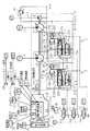
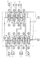
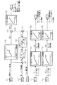
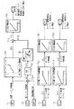
図1において、1及び2は例えば斜板式の可変容量型の油圧ポンプであり、油圧ポンプ1,2の吐出路3,4には図2に示す弁装置5が接続され、この弁装置5を介して複数のアクチュエータ50〜56に圧油を送り、これらアクチュエータを駆動する。
【0041】
9は固定容量型のパイロットポンプであり、パイロットポンプ9の吐出路9aにはパイロットポンプ9の吐出圧力を一定圧に保持するパイロットリリーフ弁9bが接続されている。
【0042】
油圧ポンプ1,2及びパイロットポンプ9は原動機10の出力軸11に接続され、原動機10により回転駆動される。12は冷却ファン、13は熱交換器である。
【0043】
弁装置5の詳細を説明する。
【0044】
図2において、弁装置5は、流量制御弁5a〜5dと流量制御弁5e〜5iの2つの弁グループを有し、流量制御弁5a〜5dは油圧ポンプ1の吐出路3につながるセンタバイパスライン5j上に位置し、流量制御弁5e〜5iは油圧ポンプ2の吐出路4につながるセンタバイパスライン5k上に位置している。吐出路3,4には油圧ポンプ1,2の吐出圧力の最大圧力を決定するメインリリーフ弁5mが設けられている。
【0045】
流量制御弁5a〜5d及び流量制御弁5e〜5iはセンタバイパスタイプであり、油圧ポンプ1,2から吐出された圧油はこれらの流量制御弁によりアクチュエータ50〜56の対応するものに供給される。アクチュエータ50は走行右用の油圧モータ(右走行モータ)、アクチュエータ51はバケット用の油圧シリンダ(バケットシリンダ)、アクチュエータ52はブーム用の油圧シリンダ(ブームシリンダ)、アクチュエータ53は旋回用の油圧モータ(旋回モータ)、アクチュエータ54はアーム用の油圧シリンダ(アームシリンダ)、アクチュエータ55は予備の油圧シリンダ、アクチュエータ56は走行左用の油圧モータ(左走行モータ)であり、流量制御弁5aは走行右用、流量制御弁5bはバケット用、流量制御弁5cは第1ブーム用、流量制御弁5dは第2アーム用、流量制御弁5eは旋回用、流量制御弁5fは第1アーム用、流量制御弁5gは第2ブーム用、流量制御弁5hは予備用、流量制御弁5iは走行左用である。即ち、ブームシリンダ52に対しては2つの流量制御弁5g,5cが設けられ、アームシリンダ54に対しても2つの流量制御弁5d,5fが設けられ、ブームシリンダ52とアームシリンダ54のボトム側には、それぞれ、2つの油圧ポンプ1,2からの圧油が合流して供給可能になっている。
【0046】
流量制御弁5a〜5iの操作パイロット系を図3に示す。
【0047】
流量制御弁5i,5aは操作装置35の操作パイロット装置39,38からの操作パイロット圧TR1,TR2及びTR3,TR4により、流量制御弁5b及び流量制御弁5c,5gは操作装置36の操作パイロット装置40,41からの操作パイロット圧BKC,BKD及びBOD,BOUにより、流量制御弁5d,5f及び流量制御弁5eは操作装置37の操作パイロット装置42,43からの操作パイロット圧ARC,ARD及びSW1,SW2により、流量制御弁5hは操作パイロット装置44からの操作パイロット圧AU1,AU2により、それぞれ切り換え操作される。
【0048】
操作パイロット装置38〜44は、それぞれ、1対のパイロット弁(減圧弁)38a,38b〜44a,44bを有し、操作パイロット装置38,39,44はそれぞれ更に操作ペダル38c,39c、44cを有し、操作パイロット装置40,41は更に共通の操作レバー40cを有し、操作パイロット装置42,43は更に共通の操作レバー42cを有している。操作ペダル38c,39c、44c及び操作レバー40c,42cを操作すると、その操作方向に応じて関連する操作パイロット装置のパイロット弁が作動し、操作量に応じた操作パイロット圧が生成される。
【0049】
また、操作パイロット装置38〜44の各パイロット弁の出力ラインにはシャトル弁61〜67が接続され、これらシャトル弁61〜67には更にシャトル弁68,69,100〜103が階層的に接続され、シャトル弁61,63,64,65,68,69,101により操作パイロット装置38,40,41,42の操作パイロット圧の最高圧力が油圧ポンプ1の制御パイロット圧PL1として検出され、シャトル弁62,64,65,66,67,69,100,102,103により操作パイロット装置39,41,42,43,44の操作パイロット圧の最高圧力が油圧ポンプ2の制御パイロット圧PL2として検出される。
【0050】
以上のような油圧駆動系に本発明の油圧ポンプのトルク制御装置を備えたエンジン・ポンプ制御装置が設けられている。以下、その詳細を説明する。
【0051】
図1において、油圧ポンプ1,2にはそれぞれレギュレータ7,8が備えられ、これらレギュレータ7,8で油圧ポンプ1,2の容量可変機構である斜板1a,2aの傾転位置を制御し、ポンプ吐出流量を制御する。
【0052】
油圧ポンプ1,2のレギュレータ7,8は、それぞれ、傾転アクチュエータ20A,20B(以下、適宜20で代表する)と、図3に示す操作パイロット装置38〜44の操作パイロット圧に基づいてポジティブ傾転制御をする第1サーボ弁21A,21B(以下、適宜21で代表する)と、油圧ポンプ1,2の全馬力制御をする第2サーボ弁22A,22B(以下、適宜22で代表する)とを備え、これらのサーボ弁21,22によりパイロットポンプ9から傾転アクチュエータ20に作用する圧油の圧力を制御し、油圧ポンプ1,2の傾転位置が制御される。
【0053】
傾転アクチュエータ20、第1及び第2サーボ弁21,22の詳細を説明する。
【0054】
各傾転アクチュエータ20は、両端に大径の受圧部20aと小径の受圧部20bとを有する作動ピストン20cと、受圧部20a,20bが位置する受圧室20d,20eとを有し、両受圧室20d,20eの圧力が等しいときは作動ピストン20cは図示右方向に移動し、これにより斜板1a又は2aの傾転は小さくなりポンプ吐出流量が減少し、大径側の受圧室20dの圧力が低下すると、作動ピストン20cは図示左方向に移動し、これにより斜板1a又は2aの傾転が大きくなりポンプ吐出流量が増大する。また、大径側の受圧室20dは第1及び第2サーボ弁21,22を介してパイロットポンプ9の吐出路9aに接続され、小径側の受圧室20eは直接パイロットポンプ9の吐出路9aに接続されている。
【0055】
ポジティブ傾転制御用の各第1サーボ弁21は、ソレノイド制御弁30又は31からの制御圧力により作動し油圧ポンプ1,2の傾転位置を制御する弁であり、制御圧力が高いときは弁体21aが図示右方向に移動し、パイロットポンプ9からのパイロット圧を減圧せずに受圧室20dに伝達し、油圧ポンプ1又は2の傾転を小さくし、制御圧力が低下するにしたがって弁体21aがバネ21bの力で図示左方向に移動し、パイロットポンプ9からのパイロット圧を減圧して受圧室20dに伝達し、油圧ポンプ1又は2の傾転を大きくする。
【0056】
全馬力制御用の各第2サーボ弁22は、油圧ポンプ1,2の吐出圧力とソレノイド制御弁32からの制御圧力により作動し、油圧ポンプ1,2の全馬力制御をする弁であり、ソレノイド制御弁32により油圧ポンプ1,2の最大吸収トルクが制限制御される。
【0057】
即ち、油圧ポンプ1及び2の吐出圧力とソレノイド制御弁32からの制御圧力が操作駆動部の受圧室22a,22b,22cにそれぞれ導かれ、油圧ポンプ1,2の吐出圧力の油圧力の和がバネ22dの弾性力と受圧室22cに導かれる制御圧力の油圧力との差で決まる設定値より低いときは、弁体22eは図示右方向に移動し、パイロットポンプ9からのパイロット圧を減圧して受圧室20dに伝達して油圧ポンプ1,2の傾転を大きくし、油圧ポンプ1,2の吐出圧力の油圧力の和が同設定値よりも高くなるにしたがって弁体22aが図示左方向に移動し、パイロットポンプ9からのパイロット圧を減圧せずに受圧室20dに伝達し、油圧ポンプ1,2の傾転を小さくする。また、ソレノイド制御弁32からの制御圧力が低いときは、上記設定値を大きくし、油圧ポンプ1,2の高めの吐出圧力から油圧ポンプ1,2の傾転を減少させ、ソレノイド制御弁32からの制御圧力が高くなるにしたがって上記設定値を小さくし、油圧ポンプ1,2の低めの吐出圧力から油圧ポンプ1,2の傾転を減少させる。
【0058】
ソレノイド制御弁30,31,32は駆動電流SI1,SI2,SI3により作動する比例減圧弁であり、駆動電流SI1,SI2,SI3が最小のときは、出力する制御圧力が最高になり、駆動電流SI1,SI2,SI3が増大するに従って出力する制御圧力が低くなるよう動作する。駆動電流SI1,SI2,SI3は図4に示すコントローラ70より出力される。
【0059】
原動機10はディーゼルエンジンであり、燃料噴射装置14を備えている。この燃料噴射装置14はガバナ機構を有し、図4に示すコントローラ70からの出力信号による目標エンジン回転数NR1になるようにエンジン回転数を制御する。
【0060】
燃料噴射装置のガバナ機構のタイプは、コントローラからの電気的な信号による目標エンジン回転数になるよう制御する電子ガバナ制御装置や、機械式の燃料噴射ポンプのガバナレバーにモータを連結し、コントローラからの指令値に基づいて目標エンジン回転数になるよう予め定められた位置にモータを駆動し、ガバナレバー位置を制御するような機械式ガバナ制御装置がある。本実施形態の燃料噴射装置14はいずれのタイプも有効である。
【0061】
原動機10にはエンジン始動用のキースイッチ89が設けられ、オペレータがキースイッチ89のキー挿入部にキーを差し込み、エンジン始動位置まで回転させると、エンジンスタート信号STRが発生し、この信号STRが図4に示すコントローラ70に取り込まれ、図示しないスタータを回転させ、原動機10を始動する。
【0062】
また、原動機10には、目標エンジン回転数をオペレータが手動で入力する目標エンジン回転数入力部71が設けられ、図4に示すようにその目標エンジン回転数NR0の入力信号がコントローラ70に取り込まれ、コントローラ70から目標回転数NR1の信号が燃料噴射装置14へ出力され、原動機10の回転数が制御される。目標エンジン回転数入力部71はポテンショメータのような電気的入力手段によって直接コントローラ70に入力するものであってよく、オペレータが基準となるエンジン回転数の大小を選択するものである。
【0063】
また、原動機10の実回転数NE1を検出する回転数センサー72と、油圧ポンプ1,2の制御パイロット圧PL1,PL2を検出する圧力センサー73,74(図3参照)が設けられている。
【0064】
更に、原動機10の環境を検出するセンサーとして、大気圧センサー75、燃料温度センサー76、冷却水温度センサー77、吸気温度センサー78、吸気圧力センサー79、排気温度センサー80、排気圧力センサー81、エンジンオイル温度センサー82が設けられ、それぞれ、大気圧センサー信号TA、燃料温度センサー信号TF、冷却水温度センサー信号TW、吸気温度センサー信号TI、吸気圧力センサー信号PI、排気温度センサー信号TO、排気圧力センサー信号PO、エンジンオイル温度センサー信号TLを出力する。
【0065】
コントローラ70の全体の信号の入出力関係を図4に示す。
【0066】
コントローラ70は上記のようにキースイッチ89のエンジンスタート信号STRを入力し、図示しないスタータを駆動し原動機10を始動させる。また、目標エンジン回転数入力部71の目標エンジン回転数NR0の信号を入力し、目標回転数NR1の信号を燃料噴射装置14へ出力し、原動機10の回転数を制御する。
【0067】
また、コントローラ70は、回転数センサー72の実回転数NE1の信号、圧力センサー73,74のポンプ制御パイロット圧PL1,PL2の信号、環境センサー75〜82の大気圧センサー信号TA、燃料温度センサー信号TF、冷却水温度センサー信号TW、吸気温度センサー信号TI、吸気圧力センサー信号PI、排気温度センサー信号TO、排気圧力センサー信号PO、エンジンオイル温度センサー信号TLを入力し、所定の演算処理を行って駆動電流SI1,SI2,SI3をソレノイド制御弁30〜32に出力し、油圧ポンプ1,2の傾転位置、即ち吐出流量を制御する。
【0068】
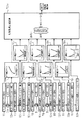
コントローラ70の油圧ポンプ1,2の制御に関する処理機能を図5及び図6に示す。
【0069】
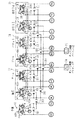
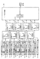
図5において、コントローラ70は、ポンプ目標傾転演算部70a,70b、ソレノイド出力電流演算部70c,70d、ベーストルク演算部70e、回転数偏差演算部70f、トルク変換部70g、リミッタ演算部70h、スピードセンシングトルク偏差補正部70i、ベーストルク補正部70j、ソレノイド出力電流演算部70kの各機能を有している。
【0070】
ポンプ目標傾転演算部70aは、油圧ポンプ1側の制御パイロット圧PL1の信号を入力し、これをメモリに記憶してあるテーブルに参照させ、そのときの制御パイロット圧PL1に応じた油圧ポンプ1の目標傾転θR1を演算する。この目標傾転θR1はパイロット操作装置38,40,41,42の操作量に対するポジティブ傾転制御の基準流量メータリングであり、メモリのテーブルには制御パイロット圧PL1が高くなるに従って目標傾転θR1も増大するようPL1とθR1の関係が設定されている。
【0071】
ソレノイド出力電流演算部70cは、θR1に対してこのθR1が得られる油圧ポンプ1の傾転制御用の駆動電流SI1を求め、これをソレノイド制御弁30に出力する。
【0072】
ポンプ目標傾転演算部70b、ソレノイド出力電流演算部70dでも、同様にポンプ制御パイロット圧PL2の信号から油圧ポンプ2の傾転制御用の駆動電流SI2を算出し、これをソレノイド制御弁31に出力する。
【0073】
ベーストルク演算部70eは、目標エンジン回転数NR0の信号を入力し、これをメモリに記憶してあるテーブルに参照させ、そのときの目標エンジン回転数NR0に応じたポンプベーストルクTROを算出する。メモリのテーブルには、目標エンジン回転数NR0が上昇するに従ってポンプベーストルクTROが増大するようNR0とTROの関係が設定されている。
【0074】
回転数偏差演算部70fは、目標エンジン回転数NR1と実エンジン回転数NE1の差の回転数偏差ΔNを算出する。
【0075】
トルク変換部70gは、回転数偏差ΔNにスピードセンシングのゲインKNを掛け、スピードセンシングトルク偏差ΔTOを算出する。
【0076】
リミッタ演算部70hは、スピードセンシングトルク偏差ΔTOに上限下限リミッタを掛け、スピードセンシングトルク偏差ΔT1とする。
【0077】
スピードセンシングトルク偏差補正部70iは、このスピードセンシングトルク偏差ΔT1から図6の処理で求めたトルク補正値ΔTFLを減算し、トルク偏差ΔTNLとする。
【0078】
ベーストルク補正部70jは、ベーストルク演算部70eで求めたポンプベーストルクTROにそのトルク偏差ΔTNLを加算し、吸収トルクTR1とする。このTR1が油圧ポンプ1,2の目標最大吸収トルクとなる。
【0079】
ソレノイド出力電流演算部70kは、TR1に対してこのTR1が得られる油圧ポンプ1,2の最大吸収トルク制御用のソレノイド制御弁32の駆動電流SI3を求め、これをソレノイド制御弁32に出力する。
【0080】
このようにして駆動電流SI3を受けたソレノイド制御弁32は、前述したように油圧ポンプ1,2の最大吸収トルクを制御する。
【0081】
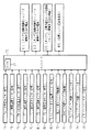
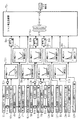
図6において、コントローラ70は、更に、補正ゲイン演算部70m〜70u、トルク補正値演算部70v、入力タイミング制御部91a,91b,91c、メモリ入出力制御部92a〜92hの各機能を有している。
【0082】
入力タイミング制御部91aは、エンジンスタート信号STRが入力されたときに図4に示すタイマー88の機能に基づき一定時間、大気圧センサー信号TAをメモリ入出力制御部92aに入力し、メモリ入出力制御部92aはその大気圧センサー信号TAを大気圧センサーメモリー値MTAとしてメモリーに取り込む。
【0083】
補正ゲイン演算部70mは、メモリーに取り込まれた大気圧センサーメモリー値MTAをメモリ入出力制御部92aを介して入力し、これを大気圧センサー信号TAとして、メモリーに記憶してあるテーブルに参照させ、大気圧センサー信号TAに応じた補正ゲインKTAを演算する。この補正ゲインKTAは、予めエンジン単体の特性に対して事前に把握した値を記憶したものである。以下に記す他の補正ゲインも同様である。
【0084】
ここで、大気圧が下がるとエンジンの出力は低下することから、メモリーのテーブルにはこれに対応して、大気圧センサー信号TAが小さくなるにしたがって補正ゲインKTAが大きくなるように、大気圧センサー信号TAと補正ゲインKTAとの関係が設定されている。
【0085】
メモリ入出力制御部92bは燃料温度センサー信号TFを燃料温度センサーメモリー値MTFとしてメモリーに取り込む。
【0086】
補正ゲイン演算部70nは、メモリーに取り込まれた燃料温度センサーメモリー値MTFをメモリ入出力制御部92bを介して入力し、これを燃料温度センサー信号TFとして、メモリーに記憶してあるテーブルに参照させ、そのときの燃料温度センサー信号TFに応じた補正ゲインKTFを演算する。
【0087】
ここで、燃料温度が低い場合あるいは高い場合は出力が低下することから、メモリーのテーブルにはこれに対応して、燃料温度センサー信号TFが小さくなるにしたがって補正ゲインKTFが大きくなり、かつ燃料温度センサー信号TFが大きくなるにしたがって補正ゲインKTFが大きくなるように、燃料温度センサー信号TFと補正ゲインKTFとの関係が設定されている。
【0088】
メモリ入出力制御部92cは冷却水温度センサー信号TWを冷却水温度センサーメモリー値MTWとしてメモリーに取り込む。
【0089】
補正ゲイン演算部70pは、メモリーに取り込まれた冷却水温度センサーメモリー値MTWをメモリ入出力制御部92cを介して入力し、これを冷却水温度センサー信号TWとして、メモリーに記憶してあるテーブルに参照させ、そのときの冷却水温度センサー信号TWに応じた補正ゲインKTWを演算する。
【0090】
ここで、冷却水温度が低い場合あるいは高い場合は出力が低下することから、メモリーのテーブルにはこれに対応して、冷却水温度センサー信号TWが小さくなるにしたがって補正ゲインKTWが大きくなり、かつ冷却水温度センサー信号TWが大きくなるにしたがって補正ゲインKTWが大きくなるように、冷却水温度センサー信号TWと補正ゲインKTWとの関係が設定されている。
【0091】
入力タイミング制御部91bは、エンジンスタート信号STRが入力されたときに図4に示すタイマー88の機能に基づき一定時間、吸気温度センサー信号TIをメモリ入出力制御部92dに入力し、メモリ入出力制御部92dはその吸気温度センサー信号TIを吸気温度センサーメモリー値MTIとしてメモリーに取り込む。
【0092】
補正ゲイン演算部70qは、メモリーに取り込まれた吸気温度センサーメモリー値MTIをメモリ入出力制御部92dを介して入力し、これを吸気温度センサー信号TIとして、メモリーに記憶してあるテーブルに参照させ、そのときの吸気温度センサー信号TIに応じた補正ゲインKTIを演算する。
【0093】
ここで、吸入空気温度が低い場合あるいは高い場合は出力が低下することから、メモリーのテーブルにはこれに対応して、吸気温度センサー信号TIが小さくなるにしたがって補正ゲインKTIが大きくなり、かつ吸気温度センサー信号TIが大きくなるにしたがって補正ゲインKTIが大きくなるように、吸気温度センサー信号TIと補正ゲインKTIとの関係が設定されている。
【0094】
入力タイミング制御部91cは、エンジンスタート信号STRが入力されたときに図4に示すタイマー88の機能に基づき一定時間、吸気圧力センサー信号PIをメモリ入出力制御部92eに入力し、メモリ入出力制御部92eはその吸気圧力センサー信号PIを吸気圧力センサーメモリー値MPIとしてメモリーに取り込む。
【0095】
補正ゲイン演算部70rは、メモリーに取り込まれた吸気圧力センサーメモリー値MPIをメモリ入出力制御部92eを介して入力し、これを吸気圧力センサー信号PIとして、メモリーに記憶してあるテーブルに参照させ、そのときの吸気圧力センサー信号PIに応じた補正ゲインKPIを演算する。
【0096】
ここで、吸入空気圧力が低い場合あるいは高い場合は出力が低下することから、メモリーのテーブルにはこれに対応して、吸気圧力センサー信号PIが小さくなるにしたがって補正ゲインKPIが大きくなり、かつ吸気圧力センサー信号PIが大きくなるにしたがって補正ゲインKPIが大きくなるように、吸気圧力センサー信号PIと補正ゲインKPIとの関係が設定されている。
【0097】
メモリ入出力制御部92fは排気温度センサー信号TOを排気温度センサーメモリー値MTOとしてメモリーに取り込む。
【0098】
補正ゲイン演算部70sは、メモリーに取り込まれた排気温度センサーメモリー値MTOをメモリ入出力制御部92fを介して入力し、これを排気温度センサー信号TOとして、メモリーに記憶してあるテーブルに参照させ、そのときの排気温度センサー信号TOに応じた補正ゲインKTOを演算する。
【0099】
ここで、排気温度が低い場合あるいは高い場合は出力が低下することから、メモリーのテーブルにはこれに対応して、排気温度センサー信号TOが小さくなるにしたがって補正ゲインKTOが大きくなり、かつ排気温度センサー信号TOが大きくなるにしたがって補正ゲインKTOが大きくなるように、排気温度センサー信号TOと補正ゲインKTOとの関係が設定されている。
【0100】
メモリ入出力制御部92gは排気圧力センサー信号POを排気圧力センサーメモリー値MPOとしてメモリーに取り込む。
【0101】
補正ゲイン演算部70tは、メモリーに取り込まれた排気圧力センサーメモリー値MPOをメモリ入出力制御部92gを介して入力し、これを排気圧力センサー信号POとして、メモリーに記憶してあるテーブルに参照させ、そのときの排気圧力センサー信号POに応じた補正ゲインKPOを演算する。
【0102】
ここで、排気圧力が上昇するにつれて出力は低下することから、メモリーのテーブルにはこれに対応して、排気圧力センサー信号POが大きくなるにしたがって補正ゲインKPOが大きくなるように、排気圧力センサー信号POと補正ゲインKPOとの関係が設定されている。
【0103】
メモリ入出力制御部92hはエンジンオイル温度センサー信号TLをエンジンオイル温度センサーメモリー値MTLとしてメモリーに取り込む。
【0104】
補正ゲイン演算部70uは、メモリーに取り込まれたエンジンオイル温度センサーメモリー値MTLをメモリ入出力制御部92hを介して入力し、これをエンジンオイル温度センサー信号TLとして、メモリーに記憶してあるテーブルに参照させ、そのときのエンジンオイル温度センサー信号TLに応じた補正ゲインKTLを演算する。
【0105】
ここで、エンジンオイル温度が低い場合あるいは高い場合は出力が低下することから、メモリーのテーブルにはこれに対応して、エンジンオイル温度センサー信号TLが小さくなるにしたがって補正ゲインKTLが大きくなり、かつエンジンオイル温度センサー信号TLが大きくなるにしたがって補正ゲインKTLが大きくなるように、エンジンオイル温度センサー信号TLと補正ゲインKTLとの関係が設定されている。
【0106】
以上において、メモリ入出力制御部92a,92d,92eは、入力タイミング制御部91a,92b,91cがONしセンサー信号を入力している間、即ちエンジンスタート信号STRが入力されたときに一定時間だけ、コントローラ70の演算サイクルを基準にしたタイミングでそれぞれの信号をメモリーに取り込み、メモリ入出力制御部92b,92c,92f〜92hは、常時コントローラ70の演算サイクルを基準にしたタイミングでそれぞれの信号をメモリーに取り込む。例えば、コントローラ70の演算サイクルを10msとすれば、メモリ入出力制御部92a,92d,92eは、エンジンスタート信号STRの入力後の一定時間、例えば5分間、6演算サイクル毎(60ms毎)にそれぞれの信号をメモリーに取り込む。メモリ入出力制御部92b,92c,92f〜92hも例えば6演算サイクル毎(60ms毎)にそれぞれの信号をメモリーに取り込む。この場合、メモリ入出力制御部92b,92c,92f〜92hは6演算サイクル毎(60ms毎)に一度に全ての信号をメモリに取り込んでも良いし、各演算サイクル毎に順番に1つづつ信号をメモリーに取り込んでも良い。
【0107】
トルク補正値演算部70vは、上記の補正ゲイン演算部70m〜70uでそれぞれ演算した補正ゲインを重み付けして、トルク補正値ΔTFLを算出する。この算出方法は、予めエンジン固有の性能に対してそれぞれの補正ゲインに対する出力低下の量を事前に把握し、求めようとするトルク補正値ΔTFLに対する基準のトルク補正値ΔTBを定数として内部に備える。更に、それぞれの補正ゲインの重み付けを予め把握し、その重み付けの補正分を行列A,B,C,D,E,F,G,Hとしてコントローラ内部に備える。これらの値を用いて図6のトルク補正値演算ブロックで示すような計算でトルク補正値ΔTFLを算出する。
【0108】
図6の計算式は一次式で表したが、その目的は最終トルク補正値ΔTFLを算出することであるので、例えば2次式等で計算しても効果は同じである。
【0109】
以上において、目標エンジン回転数入力部71は原動機(エンジン)10の目標回転数を指令する入力手段を構成し、回転数センサー72は原動機の実回転数を検出する第1検出手段を構成し、ベーストルク演算部70e、回転数偏差演算部70f、トルク変換部70g、リミッタ演算部70h、ベーストルク補正部70j、ソレノイド出力電流演算部70k、ソレノイド制御弁32、第2サーボ弁22A,22Bは、上記目標回転数と実回転数の偏差を算出しその偏差に基づいて油圧ポンプ1,2の最大吸収トルクを制御するスピードセンシング制御手段を構成する。
【0110】
また、環境センサー75〜82は、原動機10の環境に係わる状態量を検出する第2検出手段を構成し、キースイッチ89、入力タイミング制御部91a〜91c、メモリ入出力制御部92a〜92h、補正ゲイン演算部70m〜70uは、第2検出手段の検出値に基づいて、原動機10の環境に係わる状態量毎に、予め定めた状態量と原動機の出力変化の影響量との関係からそのときの状態量の検出値に対応する出力変化の影響量を演算する個別演算手段を構成し、トルク補正値演算部70v、スピードセンシングトルク偏差補正部70iは、その個別演算手段の演算値に応じて油圧ポンプ1,2の最大吸収トルクを補正するトルク補正手段を構成する。
【0111】
更に、キースイッチ89、入力タイミング制御部91a〜91cは、上記個別演算手段に設けられ、原動機10の環境に係わる状態量のうちの特定の状態量について、原動機10の始動時にのみ上記第2検出手段の検出値を入力する入力制御手段を構成する。
【0112】
そして、以上のスピードセンシング制御手段、第2検出手段、個別演算手段、トルク補正手段、入力制御手段は、本発明の油圧ポンプのトルク制御装置を構成する。
【0113】
次に、以上のように構成した本実施形態の動作の特徴を説明する。
【0114】
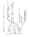
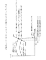
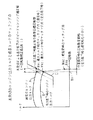
図7は本発明のトルク制御装置によるエンジン出力トルクとポンプ吸収トルクのマッチング点を示す図である。図8は、比較のため、従来のトルク制御装置によるエンジン出力トルクと油圧ポンプ吸収トルクのマッチング点を示す図である。これらマッチング点は、共に、目標回転数を一定とした場合でエンジンの出力トルクが通常時と環境の変化による出力低下時のものである。
【0115】
ここで、従来のスピードセンシング制御としては、図5のスピードセンシングトルク偏差補正部70iがなく、リミッタ演算部70hで得たスピードセンシングトルク偏差ΔT1を直接ベーストルク補正部70jにてポンプベーストルクTROに加算し、これを目標最大吸収トルクとするものを想定する。
【0116】
まず、エンジンの出力低下は、エンジンを取り巻く環境で変わってくる。例えば使用する高度が高地であった場合は、大気圧の低下でエンジン出力トルクは曲線Aから曲線Bのように低下する。
【0117】
エンジン負荷(油圧ポンプの吸収トルク)が軽いときは、燃料噴射装置(ガバナ機構)のレギュレーション上の点がエンジン負荷と出力トルクのマッチング点となり、目標回転数をNaとした場合、軽負荷時にはエンジンの出力低下に係わらずエンジン回転数は目標回転数Naより少し高い、ガバナ機構のレギュレーション特性線上の点Na0となる。これは、図7の本実施形態も図8の従来技術も同じである。
【0118】
エンジン負荷が増加した場合、エンジン出力トルク曲線A,B上の点がエンジン負荷と出力トルクのマッチング点となる。この点を最大トルクマッチング点と呼ぶ。
【0119】
通常出力時は、最大トルクマッチング点はエンジン出力トルク曲線A上の目標回転数Naに対応する点Maである。油圧ショベルの作業中に負荷が軽負荷から高負荷になるにつれてエンジン回転数がNa0からNaに低下する。このことも、図7の本実施形態と図8の従来技術とで同じである。
【0120】
環境の変化によるエンジン出力低下時、従来技術の場合は、スピードセンシング制御によりエンジン回転数の低下(回転数偏差ΔNの増大)に応じて油圧ポンプの吸収トルクを低下させる。このとき、エンジン回転数の低下(回転数偏差ΔNの増大)に対するポンプ最大吸収トルクの低下の割合は図5に示すトルク変換部70gのゲインKで定まる。これをポンプ最大吸収トルクのスピードセンシングゲインと呼ぶと、図8の「C」の特性がこれに相当する。
【0121】
従来のスピードセンシング制御では、図5のスピードセンシングトルク偏差補正部70iがないので、環境の変化でエンジン出力が低下しても、このスピードセンシングゲインCの特性は一定である。このため、エンジン負荷の増加時、エンジン出力が曲線Aから曲線Bに低下すると、スピードセンシング制御によりエンジン回転数の低下に応じてゲインCの特性に沿って油圧ポンプの吸収トルクを低下させ、Ma1の点で油圧ポンプの吸収トルクとエンジンの出力トルクが等しくなり、マッチングする。即ち、マッチング点はMaからMa1に移動する。
【0122】
以上より、環境の変化でエンジン出力が低下した場合は、油圧ショベルの作業中に負荷が軽負荷から高負荷になるにつれてエンジン回転数がNa0からNa1(<Na)に大きく低下する。
【0123】
例えば標高の高いところで掘削作業をしようとする場合、バケットが空の状態ではエンジン回転数はオペレータの入力した目標回転数Naよりやや高めのNa0となるが、土砂を掘削するとエンジン回転数がNa1へと低下する。
【0124】
これによって騒音やエンジン回転数からくる車体の振動が変化し、作業者に疲労感を訴える。
【0125】
以上の従来技術に対し、本実施形態の場合は、環境の変化によりエンジンの出力が低下すると、センサー75〜82がその環境の変化を検出し、補正ゲイン演算部70m〜70u及びトルク補正値演算部70vがその信号を入力してエンジン出力の低下をトルク補正値ΔTFLとして推定し、スピードセンシングトルク偏差補正部70i及びベーストルク補正部70jでスピードセンシングトルク偏差ΔTIからトルク補正値ΔTFLを減じたトルク偏差ΔTNLをポンプベーストルクTROに加算し、吸収トルクTR1(目標最大吸収トルク)を求める処理を行う。この処理は、環境の変化によるエンジンの出力低下分をトルク補正値ΔTFLとして計算し、この分だけポンプベーストルクTROを減じることで目標最大吸収トルクTR1を予め減じたことに相当し、エンジン出力の低下に従って(トルク補正値ΔTFLの増加に従って)図8に示すポンプ最大吸収トルクのスピードセンシングのゲインCの特性はトルク補正値ΔTFLの分だけ下方に移動する。
【0126】
その結果、エンジン出力低下時のポンプ吸収トルクとのマッチング点はMa2点となり、エンジン回転数は通常出力時のNaと変わらず、エンジン回転数の低下の少ない良好な作業性を確保できる。
【0127】
また、本発明は、以上のように環境の変化で原動機の出力が低下した場合も、高負荷時において、原動機の回転数の低下を少なくしているが、このためにはセンサー75〜82という多数のセンサーが必要である。このように多数のセンサがある場合、全てのセンサーの信号をそのまま入力してメモリに取り込み、それによってトルク補正値を演算すると、コントローラ70の処理能力は限られているので、センサー信号のメモリの取り込みに多くの時間を費やし、特にコントローラ70に他の処理機能が組まれている場合は、処理速度が遅くなる。
【0128】
しかし、センサー値はその検出対象である環境状態量の種類によって性格が違っており、比教的変動の大きいものと少ないものがある。例えば、大気圧は油圧ショベルの作業中に大きく変化することはなく、その結果センサー値は、作業中に大きく変動しない。吸気温度、吸気圧力のセンサー値も同様である。一方、エンジンオイル温度は作業状態によって進展速度が一定でなく、かつ作業中に大きく変動する。燃料温度、冷却水温度、排気温度、排気圧力のセンサー値も同様である。
【0129】
本実施形態では、このようなセンサー値の性格の相違に着目し、作業中の変化が小さいセンサー値である大気圧センサー75、吸気温度センサー78、吸気圧力センサー79のセンサー信号TA,TI,PIに対しては入力タイミング制御部91a〜91cを設け、エンジンスタート信号STRが入力されたときに一定時間だけそれぞれの信号をメモリーに取り込みようにしている。このため、常時センサー信号TA,TI,PIをメモリーに取り込む場合に比較してコントローラ70の処理量が減り、コントローラ70に余裕ができ、他の処理を行うような場合でも比較的速い処理が行える。また、作業中の変化が比較的大きいセンサー値である燃料温度センサー76、冷却水温度センサー77、排気温度センサー80、排気圧力センサー81、エンジンオイル温度センサー82のセンサー信号TF,TW,TO,PO,TLに対しては、常時所定のタイミングでそれぞれの信号をメモリに取り込んでトルク補正することで、上記のように環境の変化で原動機の出力が低下した場合の原動機の回転数の低下を少なくできる。
【0130】
以上のように本実施形態によれば、環境の変化でエンジン出力が低下した場合も、高負荷時においてエンジン回転数の低下を少なくでき、良好な作業性を確保できる。
【0131】
また、常に回転数偏差による油圧ポンプの吸収トルクを制御するスピードセンシングは従来通り行っており、急負荷がかかったときや予期せぬことによるエンジンの出力低下に対してもエンジン停止を防止できる。
【0132】
更に、スピードセンシング制御をしているので油圧ポンプの吸収トルクを予め余裕を持って設定する必要がなく、エンジン出力が従来通り有効に利用できる。例えば機器の性能のばらつきや径年変化等でエンジン出力が低下しても高負荷時のエンジン停止を防止できる。
【0133】
また、コントローラ70の処理能力を有効に使うことができるので、コントローラ70の限られた処理能力で、コントローラ70で他の処理を行うような場合でも比較的速い処理が行える。
【0134】
なお、上記実施形態ではスピードセンシングトルク偏差補正部70iでスピードセンシングトルク偏差ΔTIからトルク補正値ΔTFLを減じたが、ベーストルク補正部70jでトルク偏差ΔTNLからトルク補正値ΔTFLを減じても良いことは、勿論である。
【0135】
本発明の第2の実施形態を図9〜図11により説明する。図中、図5〜図7に示すものと同等のものには同じ符号を付している。
【0136】
図9において、コントローラは、ポンプ目標傾転演算部70a,70b、ソレノイド出力電流演算部70c,70d、ベーストルク演算部70e、回転数偏差演算部70Af、トルク変換部70g、リミッタ演算部70h、ベーストルク補正部70j、ソレノイド出力電流演算部70kの各機能を有している。
【0137】
回転数偏差演算部70Afは、目標エンジン回転数NR1と実エンジン回転数NE1の差を求め、更に図10の処理で求めた回転数補正値ΔNFLを減算し、回転数偏差ΔNを算出する。
【0138】
トルク変換部70gでは、この回転数偏差ΔNにスピードセンシングのゲインKNを掛け、スピードセンシングトルク偏差ΔTOを算出した後、リミッタ演算部70hでスピードセンシングトルク偏差ΔTOに上限下限リミッタを掛け、スピードセンシングトルク偏差ΔT1とし、ベーストルク補正部70jではこのスピードセンシングトルク偏差ΔT1とポンプベーストルクTROとから吸収トルクTR1(目標最大吸収トルク)を求める。
【0139】
それ以外は、図5に示す第1の実施形態と同じである。
【0140】
図10において、コントローラは、更に、補正ゲイン演算部70m〜70u、回転数補正値演算部70Av、入力タイミング制御部91a,91b,91c、メモリ入出力制御部92a〜92hの各機能を有している。
【0141】
入力タイミング制御部91a,91b,91c、メモリ入出力制御部92a〜92h、補正ゲイン演算部70m〜70uでの処理は図6に示した第1の実施形態と同じである。
【0142】
回転数補正値演算部70Avは、補正ゲイン演算部70m〜70uでそれぞれ演算した補正ゲインを重み付けして、回転数補正値ΔNFLを算出する。この算出方法は、予めエンジン固有の性能に対してそれぞれの補正ゲインに対する出力低下の量を事前に把握し、求めようとする回転数補正値ΔNFLに対する基準の回転数補正値ΔNBを定数として内部に備える。更に、それぞれの補正ゲインの重み付けを予め把握し、その重み付けの補正分を行列A,B,C,D,E,F,G,Hとしてコントローラ内部に備える。これらの値を用いて図10の回転数補正値演算ブロックで示すような計算で回転数補正値ΔTFLを算出する。
【0143】
この場合も、図6の計算式は例えば2次式等で計算しても効果は同じである。
【0144】
ソレノイド出力電流演算部70jで生成された駆動電流SI3は図1に示すソレノイド制御弁32に出力され、前述したように油圧ポンプ1,2の最大吸収トルクを制御する。
【0145】
以上において、本実施形態では、キースイッチ89、入力タイミング制御部91a〜91c、メモリ入出力制御部92a〜92h、補正ゲイン演算部70m〜70uは、第1の実施形態と同様に、第2検出手段(環境センサー75〜82)の検出値に基づいて、原動機10の環境に係わる状態量毎に、予め定めた状態量と原動機の出力変化の影響量との関係からそのときの状態量の検出値に対応する出力変化の影響量を演算する個別演算手段を構成し、回転数補正値演算部70Av、回転数偏差演算部70Afは、その個別演算手段の演算値に応じて油圧ポンプ1,2の最大吸収トルクを補正するトルク補正手段を構成する。
【0146】
以上のように構成した本実施形態においては、環境の変化によるエンジンの出力低下時は、センサー75〜82の信号を入力して補正ゲイン演算部70m〜70u及び回転数補正値演算部70Avでエンジン出力の低下を回転数補正値ΔNFLとして推定し、回転数偏差演算部70Afで目標エンジン回転数NR1と実エンジン回転数NE1の偏差から更に回転数補正値ΔNFLを減じ、この減じた回転数偏差ΔNからスピードセンシングトルク偏差ΔTNLを求め、吸収トルクTR1(目標最大吸収トルク)を求める処理を行う。この処理は、環境の変化によるエンジンの出力低下分を回転数補正値ΔNFLとして計算し、この分だけ目標エンジン回転数NROを減じることで目標最大吸収トルクTR1を予め減じたことに相当し、エンジン出力の低下に従って(回転数補正値ΔTFLの増加に従って)図11に示すポンプ最大吸収トルクのスピードセンシングのゲインCの特性は回転数補正値ΔNFLの分だけ図示左方に移動する。
【0147】
その結果、エンジン出力低下時のポンプ吸収トルクとのマッチング点は、図7に示す第1の実施形態と同様、Ma2点となり、エンジン回転数は通常出力時のNaと変わらない。
【0148】
従って、本実施形態によって、エンジン回転数の低下の少ない良好な作業性を確保できると共に、スピードセンシング制御により急負荷がかかったときや予期せぬことによるエンジンの出力低下に対してもエンジン停止を防止できるなど、第1の実施形態と同様の効果が得られる。
【0149】
また、本実施形態でも、作業中の変化が小さいセンサー値である大気圧センサー75、吸気温度センサー78、吸気圧力センサー79のセンサー信号TA,TI,PIに対しては入力タイミング制御部91a〜91cを設け、エンジンスタート信号STRが入力されたときに一定時間だけそれぞれの信号をメモリーに取り込むようにしたので、コントローラ70に余裕ができ、速い処理が行える。
【0150】
なお、上記実施形態では回転数偏差演算部70Afで目標エンジン回転数NR1と実エンジン回転数NE1の偏差から更に回転数補正値ΔNFLを減じたが、これは目標エンジン回転数NR1に回転数補正値ΔNFLを加算したものを実エンジン回転数NE1から減じたことと同じであり、目標エンジン回転数NR1に回転数補正値ΔNFLを加算する手段を設け、回転数偏差演算部70Afではこの加算値を実エンジン回転数NE1から減じても良い。
【0151】
本発明の第3の実施形態を図12により説明する。本実施形態は、作業中変動の少ないセンサー値の処理に関し、更にコントローラの処理量を減らすものである。図中、図6に示した機能と同等のものには同じ符号を付している。
【0152】
図12において、本実施形態に係わるコントローラは、補正ゲイン演算部70m〜70u、トルク補正値演算部70v、入力タイミング制御部91a,91b,91c、メモリ入出力制御部92a〜92hに加え、更に演算タイミング制御部93a〜93c及びメモリ入出力制御部94a〜94cの各機能を有している。
【0153】
補正ゲイン演算部70m〜70u、トルク補正値演算部70v、入力タイミング制御部91a,91b,91c、メモリ入出力制御部92a〜92hでの処理は図6に示した第1の実施形態と同じである。
【0154】
演算タイミング制御部93aは、エンジンスタート信号STRが入力されたときに図4に示すタイマー88の機能に基づき一定時間、補正ゲイン演算部70mを起動し、補正ゲイン演算部70mはその間、メモリーに取り込まれた大気圧センサーメモリー値MTAをメモリ入出力制御部92aを介して入力し、これを大気圧センサー信号TAとして補正ゲインKTAを演算する。演算タイミング制御部93b,93cも同様に、エンジンスタート信号STRが入力されたときに図4に示すタイマー88の機能に基づき一定時間、補正ゲイン演算部70q,70rを起動し、補正ゲイン演算部70q,70rはその間、メモリーに取り込まれた吸気温度センサーメモリー値MTI、吸気圧力センサーメモリー値MPIをメモリ入出力制御部92d,92eを介して入力し、これを吸気温度センサー信号TI、吸気圧力センサー信号PIとして補正ゲインKTI,KPIを演算する。
【0155】
メモリ入出力制御部93aは、補正ゲイン演算部70mで計算した補正ゲインKTAの値を補正ゲインメモリー値MKTAとしてメモリーに取り込む。メモリ入出力制御部93b,93cも同様に、補正ゲイン演算部70q,70rで計算した補正ゲインKTI,KPIの値を補正ゲインメモリー値MKTI,MKPIとしてメモリーに取り込む。
【0156】
トルク補正値演算部70vは、補正ゲインKTA,KTI,KPIに関してはメモリーに取り込まれた補正ゲインメモリー値MKTA,MKTI,MKPIをメモリ入出力制御部93a〜93cを介して入力し、その他の補正ゲインに関してはそれぞれの補正ゲイン演算部から直接入力し、補正ゲインの重み付けをしてトルク補正値ΔTFLを算出する。
【0157】
以上のように構成した本実施形態によれば、補正ゲイン演算部70m,70q,70rはエンジン始動後の一定時間だけ演算を行うので、コントローラの処理量が更に減少し、コントローラの処理能力を更に有効に使うことができ、コントローラの処理速度を更に速くできる。
【0158】
なお、以上の実施形態では、入力タイミング制御部ではエンジンスタート信号STRを入力し、この信号の入力時を原動機10の始動時と判断し、状態量の検出値の入力を行ったが、キースイッチ89の操作でコントローラの内部電源がONされたときに、その内部電源のON時を原動機の始動時と判断して状態量の検出値を入力してもよい。キースイッチ89にキーを差し込んでエンジン始動位置まで回転させるとき、コントローラの内部電源のON位置はエンジン始動位置の手前にあるため、キースイッチ89をエンジン始動位置まで回転させると、必ずコントローラの内部電源のON位置を通ることになる。このため、コントローラの内部電源のON時を原動機の始動時とみなすことができ、コントローラの内部電源のON時に状態量の検出値を入力しても、エンジンスタート信号STRに状態量の検出値を入力したのと実質的に同様の効果が得られる。
【0159】
【発明の効果】
本発明によれば、環境の変化で原動機の出力が低下した場合も、高負荷時において、原動機の回転数の低下を少なくでき、良好な作業性が確保できる。
【0160】
また、スピードセンシング制御は従来通り行っているので、急負荷がかかったときや予期せぬことによる原動機の出力低下に対しても原動機の停止を防止できる。
【0161】
更に、スピードセンシング制御をしているので油圧ポンプの吸収トルクを予め余裕を持って設定する必要がなく、原動機出力が従来通り有効に利用できる。例えば機器の性能のばらつきや径年変化等で原動機出力が低下しても高負荷時の原動機の停止を防止できる。
【0162】
また、本発明によれば、コントローラの処理能力を有効に使うことができるので、コントローラの限られた処理能力で比較的速い処理が行える。
【図面の簡単な説明】
【図1】本発明の第1の実施形態による油圧ポンプのトルク制御装置を備えたエンジン・ポンプ制御装置を示す図である。
【図2】図1に示す油圧ポンプに接続された弁装置及びアクチュエータの油圧回路図である。
【図3】図2に示す流量制御弁の操作パイロット系を示す図である。
【図4】図1に示すコントローラの入出力関係を示す図である。
【図5】コントローラの処理機能の一部を示す機能ブロック図である。
【図6】コントローラの処理機能の他の一部を示す機能ブロック図である。
【図7】第1の実施形態によるスピードセンシング制御によるエンジン出力トルクとポンプ吸収トルクのマッチング点を示す図である。
【図8】従来のスピードセンシング制御によるエンジン出力トルクとポンプ吸収トルクのマッチング点を示す図である。
【図9】本発明の第2の実施形態によるコントローラの処理機能の一部を示す機能ブロック図である。
【図10】コントローラの処理機能の他の一部を示す機能ブロック図である。
【図11】第2の実施形態によるスピードセンシング制御によるエンジン出力トルクとポンプ吸収トルクのマッチング点を示す図である。
【図12】本発明の第3の実施形態によるコントローラの処理機能の一部を示す機能ブロック図である。
【符号の説明】
1,2 油圧ポンプ
1a,2a 斜板
5 弁装置
7,8 レギュレータ
10 原動機
14 燃料噴射装置
20A,20B 傾転アクチュエータ
21A,21B 第1サーボ弁
22A,22B 第2サーボ弁
30〜32 ソレノイド制御弁
38〜44 操作パイロット装置
50〜56 アクチュエータ
70 コントローラ
70a,70b ポンプ目標傾転演算部
70c,70d ソレノイド出力電流演算部
70e ベーストルク演算部
70f 回転数偏差演算部
70Af 回転数偏差演算部
70g トルク変換部
70h リミッタ演算部
70i スピードセンシングトルク偏差補正部
70j ベーストルク補正部
70k ソレノイド出力電流演算部
70m〜70u 補正ゲイン演算部
70v トルク補正値演算部
70Av 回転数補正値演算部
71 目標エンジン回転数入力部
72 回転数センサー
73,74 圧力センサー
75 大気圧センサー
76 燃料温度センサー
77 冷却水温度センサー
78 吸気温度センサー
79 吸気圧力センサー
80 排気温度センサー
81 排気圧力センサー
82 エンジンオイル温度センサー
88 タイマー
91a〜91c 入力タイミング制御部
92a〜92h メモリ入出力制御部
93a〜93c 演算タイミング制御部
94a〜94c メモリ入出力制御部[0001]
BACKGROUND OF THE INVENTION
The present invention relates to a torque control device for a hydraulic pump of a hydraulic construction machine, and in particular, a diesel engine is provided as a prime mover, and a hydraulic actuator is driven by pressure oil discharged from a hydraulic pump driven to rotate by the engine, thereby performing necessary work. The present invention relates to a torque control device for a hydraulic pump of a hydraulic construction machine such as a hydraulic excavator.
[0002]
[Prior art]
A hydraulic construction machine such as a hydraulic excavator generally includes a diesel engine as a prime mover, and at least one variable displacement hydraulic pump is driven to rotate by the engine, and a hydraulic actuator is driven by pressure oil discharged from the hydraulic pump. Necessary work is performed. This diesel engine is provided with input means for commanding a target rotational speed, such as an accelerator lever, and the fuel injection amount is controlled according to the target rotational speed, and the rotational speed is controlled.
[0003]
Regarding the control of the engine and the hydraulic pump in such a hydraulic construction machine, Japanese Patent Publication No. 62-8618 proposes a control method entitled “Control method of drive system including internal combustion engine and hydraulic pump”. This control method obtains the difference (rotational speed deviation) between the target rotational speed and the actual engine rotational speed from the rotational speed sensor, and uses this rotational speed deviation to control the input torque of the hydraulic pump, so-called speed sensing. It is an example of control.
[0004]
The purpose of this control is to reduce the load torque (input torque) of the hydraulic pump, prevent engine stoppage, and effectively use engine output when the actual engine speed detected against the target speed decreases. It is to be.
[0005]
[Problems to be solved by the invention]
By the way, the engine output reduction varies depending on the environment surrounding the engine. For example, when the place of use is a high altitude, the engine output torque decreases due to a decrease in atmospheric pressure.
[0006]
When the engine load is light, the regulation point of the fuel injector (governor mechanism) is the matching point between the engine load and the output torque, and the engine speed is slightly lower than the target speed regardless of the engine output drop due to environmental changes. It becomes a high point on the regulation characteristic line of the governor mechanism.
[0007]
When the engine load increases, the output torque with respect to the target rotational speed determined by the engine output torque characteristic unique to the engine becomes a matching point with the engine load. At this matching point, if the engine output decreases due to environmental changes, the speed sensing The control reduces the absorption torque of the hydraulic pump in accordance with the decrease in the engine speed, and matches in that the absorption torque of the hydraulic pump becomes equal to the output torque of the engine.
[0008]
For this reason, in the above prior art, when the engine load increases, if the engine output decreases due to environmental changes, the engine speed greatly decreases as the engine load changes from a light load to a high load. For example, if the hydraulic construction machine is a hydraulic excavator and you want to excavate at a high altitude with this hydraulic excavator, the engine speed will be slightly higher than the target speed entered by the operator when the bucket is empty, When excavating the earth and sand, the engine speed decreases significantly.
[0009]
As a result, the vibration of the vehicle body caused by noise and the engine speed changes, and the operator feels tired.
[0010]
On the other hand, in a hydraulic construction machine such as a hydraulic excavator, when a controller is mounted, the space for mounting the controller is limited, and the processing capacity (capacity) of the controller is limited accordingly. For this reason, when a program is incorporated in the controller, it is necessary to perform processing as fast as possible with the limited processing capability of the controller. In particular, when a new function is added to the controller, it is necessary to be able to perform a fast process even if there are other processes.
[0011]
An object of the present invention is to provide a hydraulic construction machine capable of reducing a decrease in the number of revolutions of a prime mover at a high load even when the output of the prime mover is lowered due to an environmental change, and performing a process as fast as possible with a limited processing capability of the controller. It is to provide a torque control device for a hydraulic pump.
[0012]
[Means for Solving the Problems]
(1) To achieve the above object, a prime mover, a variable displacement hydraulic pump driven by the prime mover, input means for commanding a target rotational speed of the prime mover, and a first detecting the actual rotational speed of the prime mover A torque control device for a hydraulic pump of a hydraulic construction machine, comprising: detection means; and speed sensing control means for calculating a deviation between the target rotational speed and the actual rotational speed and controlling a maximum absorption torque of the hydraulic pump based on the deviation. And a second detection means for detecting a state quantity relating to the environment of the prime mover, and a predetermined state quantity and a prime mover for each state quantity relating to the environment of the prime mover based on a detection value of the second detection means. Individual calculation means for calculating the influence amount of the output change corresponding to the detected value of the state quantity at that time from the relationship with the influence amount of the output change, and the hydraulic pump according to the calculation value of the individual calculation means A torque correction means for correcting the maximum absorption torque of the motor, and the individual calculation means for detecting a specific state quantity among the state quantities relating to the environment of the prime mover only when the prime mover is started. An input control means for inputting a value is provided.
[0013]
Here, the state quantity related to the environment of the prime mover detected by the second detection means includes a cooling water temperature, an intake air temperature, an engine oil temperature, an exhaust temperature, an atmospheric pressure, an intake pressure, an exhaust pressure, and the like.
[0014]
In this way, the state quantity related to the environment of the prime mover is detected by the second detection means, and the maximum absorption torque of the hydraulic pump is corrected by the torque correction means based on the detected value, so that only the output decrease of the prime mover due to the change in the environment is obtained. The maximum absorption torque of the hydraulic pump can be reduced in advance, and even if the output of the prime mover drops due to environmental changes, the prime mover speed at the maximum torque matching point will not drop significantly, and good work with little reduction in prime mover speed Can be secured.
[0015]
Further, the input control means inputs the detection value of the second detection means only at the time of starting the prime mover for the specific state quantity among the state quantities relating to the prime mover environment, so that all of the state quantities relating to the prime mover environment can be obtained. As compared with the case where the detection value is always input, the processing amount relating to the input of the detection value is reduced. For this reason, even if the processing capability of the controller is limited, relatively fast processing can be performed.
[0016]
(2) In the above (1), preferably, the input control means sets the detection value of the second detection means only at the start of the prime mover for a specific state quantity among state quantities related to the environment of the prime mover. The individual calculation means calculates the influence amount of the output change using the detection value acquired in the memory.
[0017]
As a result, for all the state quantities related to the environment of the prime mover, compared to the case where the detection values are always taken into the memory, the memory amount of the detection values is reduced, and the processing amount relating to the input of the detection values is reduced.
[0018]
(3) In the above (1), preferably, the input control means detects the specific state quantity among the state quantities related to the environment of the prime mover only when the prime mover is started. The individual calculation means is a means for fetching a value into the individual calculation means, and the individual calculation means uses a detection value acquired only when the prime mover is started for a specific state quantity related to the environment of the prime mover. Means for calculating the influence amount of the output change and fetching the calculated value into the memory are provided.
[0019]
As a result, for all the state quantities related to the environment of the prime mover, the detected value memory capture amount and output are compared to the case where the detected value is always loaded into the memory and the influence amount of the output change is calculated using the captured detection value. The calculation amount of the influence amount of the change is reduced, and faster processing can be performed.
[0020]
(4) Further, in the above (1), preferably, the input control means has third detection means for detecting the start of the prime mover, and the second detection means receives the second time for a predetermined time when the signal of the third detection means is input. The detection value of the detection means is input.
[0021]
Thus, the detection value of the second detection means can be input only when the prime mover is started.
[0022]
(5) In the above (1), preferably, the input control means inputs a start signal of the prime mover, and a detection value of the second detection means is defined as a start time of the prime mover when the start signal is inputted. Enter.
[0023]
Thus, the detection value of the second detection means can be input only when the prime mover is started.
[0024]
(6) In the above (1), the individual calculation means, a part of the torque correction means, and the input control means are configured by a controller, and the input control means includes the internal control when the internal power of the controller is turned on. The detection value of the second detection means may be input when the power is turned on when the prime mover is started.
[0025]
When starting the prime mover, since the prime mover is always started after turning on the internal power supply of the controller, even if the detection value of the second detection means is input when the internal power supply of the controller is turned on, the second detection means is only activated when the prime mover is started. Can be input.
[0026]
(7) Further, in the above (1), preferably, the specific state quantity for which the input value is inputted only when the prime mover is started by the input control means is a state quantity that is small in change during the operation of the hydraulic construction machine. .
[0027]
As described above in (1), by inputting the detection value only at the time of starting the prime mover for the state quantity in which the change during the operation of the hydraulic construction machine is small as described above, the input processing amount of the detection value is reduced. Normally, a detected value is input for a state quantity that changes greatly during operation of the hydraulic construction machine, and the correction accuracy of the maximum absorption torque by the torque correction means is maintained.
[0028]
(8) Also, in the above (1), preferably, the individual calculation means is configured to calculate, for each state quantity relating to the environment of the prime mover, a state quantity as a relation between the state quantity and the influence quantity of the output change of the prime mover. The relationship with the correction gain of the output change of the prime mover is stored in advance, and the correction gain of the output change corresponding to the detected value of the state quantity at that time is calculated as the influence amount of the output change from this relationship.
[0029]
Thereby, the individual calculation means calculates the influence amount of the output change as the correction gain for each state quantity related to the environment of the prime mover, and the torque correction means can correct the maximum absorption torque of the hydraulic pump using the correction gain.
[0030]
(9) In the above (1), preferably, the torque correction unit obtains a torque correction value of the hydraulic pump according to a calculation value of the individual calculation unit, and the hydraulic pump based on the torque correction value. Correct the maximum absorption torque.
[0031]
Thus, the maximum absorption torque of the hydraulic pump can be corrected by obtaining the torque reduction value by the torque correction means as the torque correction value.
[0032]
(10) In the above (1), the torque correction means obtains a rotation speed correction value of the prime mover according to a calculation value of the individual calculation means, and the maximum absorption torque of the hydraulic pump based on the rotation speed correction value May be corrected.
[0033]
In this way, even if the torque correction means obtains the output decrease of the prime mover due to the environmental change as the rotation speed correction value, the maximum absorption torque of the hydraulic pump can be corrected.
[0034]
(11) Further, in the above (1), preferably, the speed sensing control means calculates a pump base torque according to the target rotational speed and calculates a speed sensing torque deviation according to the rotational speed deviation. First means for adding the speed sensing torque deviation to the pump base torque to obtain the target maximum absorption torque of the hydraulic pump, and second means for restricting and controlling the maximum capacity of the hydraulic pump based on the target maximum absorption torque The torque correction means includes a third means for calculating a torque correction value for the target maximum absorption torque in accordance with a calculation value of the individual calculation means, and a speed sensing torque as a pump base torque by the first means. And a fourth means for correcting the target maximum absorption torque by subtracting the torque correction value when adding the deviation. .
[0035]
Thus, the maximum reduction torque of the hydraulic pump can be corrected by obtaining the output decrease of the prime mover due to the environmental change as a torque correction value and subtracting this torque correction value from the pump base torque to correct the target maximum absorption torque.
[0036]
(12) In the above (1), the speed sensing control means calculates a pump base torque according to the target rotational speed, and subtracts the target rotational speed from the actual rotational speed to obtain the rotational speed deviation. First means for correcting the pump base torque according to the rotational speed deviation to obtain the target maximum absorption torque of the hydraulic pump, and second means for restricting and controlling the maximum capacity of the hydraulic pump based on the target maximum absorption torque The torque correction means includes a third means for calculating a rotation speed correction value for the target rotation speed based on a calculation value of the individual calculation means, and a target rotation speed from the actual rotation speed by the first means. The rotational speed correction value may be further reduced when reducing.
[0037]
Thus, the target maximum absorption torque of the hydraulic pump can also be corrected by obtaining the output decrease of the prime mover due to the environmental change as the rotation speed correction value and further subtracting the rotation speed correction value from the actual rotation speed.
[0038]
DETAILED DESCRIPTION OF THE INVENTION
Hereinafter, embodiments of the present invention will be described with reference to the drawings. In the following embodiment, the present invention is applied to an engine / pump control device of a hydraulic excavator.
[0039]
First, a first embodiment of the present invention will be described with reference to FIGS.
[0040]
In FIG. 1,
[0041]
Reference numeral 9 denotes a fixed displacement type pilot pump, and a pilot relief valve 9 b that holds the discharge pressure of the pilot pump 9 at a constant pressure is connected to the discharge passage 9 a of the pilot pump 9.
[0042]
The
[0043]
Details of the
[0044]
In FIG. 2, the
[0045]
The flow control valves 5a to 5d and the
[0046]
FIG. 3 shows an operation pilot system for the flow rate control valves 5a to 5i.
[0047]
The flow control valves 5i and 5a are operated by the operation pilot pressures TR1, TR2 and TR3 and TR4 from the
[0048]
The
[0049]
Shuttle valves 61 to 67 are connected to the output lines of the pilot valves of the
[0050]
The engine / pump control device provided with the torque control device of the hydraulic pump of the present invention is provided in the above hydraulic drive system. Details will be described below.
[0051]
In FIG. 1, the
[0052]
The regulators 7 and 8 of the
[0053]
Details of the tilting
[0054]
Each tilting
[0055]
Each first servo valve 21 for positive tilt control is a valve that operates by the control pressure from the
[0056]
Each of the
[0057]
That is, the discharge pressures of the
[0058]
[0059]
The
[0060]
The type of governor mechanism of the fuel injection device is an electronic governor control device that controls to achieve the target engine speed based on an electrical signal from the controller, or a governor lever of a mechanical fuel injection pump that is connected to a motor. There is a mechanical governor control device that controls a governor lever position by driving a motor to a predetermined position based on a command value so as to reach a target engine speed. Any type of the fuel injection device 14 of the present embodiment is effective.
[0061]
The
[0062]
Further, the
[0063]
Further, a
[0064]
Further, as sensors for detecting the environment of the
[0065]
FIG. 4 shows the input / output relationship of the entire signal of the
[0066]
As described above, the
[0067]
In addition, the
[0068]
Processing functions related to the control of the
[0069]
In FIG. 5, the
[0070]
The pump target
[0071]
The solenoid output current calculation unit 70c obtains a drive current SI1 for tilt control of the
[0072]
Similarly, the pump target tilt calculation unit 70b and the solenoid output current calculation unit 70d also calculate the drive current SI2 for tilt control of the
[0073]
The base torque calculation unit 70e inputs a signal of the target engine speed NR0, refers to the table stored in the memory, and calculates the pump base torque TRO corresponding to the target engine speed NR0 at that time. The relationship between NR0 and TRO is set in the memory table so that the pump base torque TRO increases as the target engine speed NR0 increases.
[0074]
The rotational speed
[0075]
The
[0076]
The
[0077]
The speed sensing torque deviation correction unit 70i subtracts the torque correction value ΔTFL obtained by the processing of FIG. 6 from the speed sensing torque deviation ΔT1 to obtain a torque deviation ΔTNL.
[0078]
The base
[0079]
The solenoid output
[0080]
The
[0081]
In FIG. 6, the
[0082]
When the engine start signal STR is input, the input
[0083]
The correction
[0084]
Here, since the engine output decreases when the atmospheric pressure decreases, the atmospheric pressure sensor correspondingly increases in the memory table so that the correction gain KTA increases as the atmospheric pressure sensor signal TA decreases. A relationship between the signal TA and the correction gain KTA is set.
[0085]
The memory input / output control unit 92b takes the fuel temperature sensor signal TF into the memory as a fuel temperature sensor memory value MTF.
[0086]
The correction gain calculation unit 70n inputs the fuel temperature sensor memory value MTF taken into the memory via the memory input / output control unit 92b, and refers to the table stored in the memory as the fuel temperature sensor signal TF. Then, a correction gain KTF corresponding to the fuel temperature sensor signal TF at that time is calculated.
[0087]
Here, since the output decreases when the fuel temperature is low or high, the correction gain KTF increases as the fuel temperature sensor signal TF decreases correspondingly to the memory table, and the fuel temperature increases. The relationship between the fuel temperature sensor signal TF and the correction gain KTF is set so that the correction gain KTF increases as the sensor signal TF increases.
[0088]
The memory input / output control unit 92c takes the cooling water temperature sensor signal TW into the memory as the cooling water temperature sensor memory value MTW.
[0089]
The correction gain calculation unit 70p inputs the cooling water temperature sensor memory value MTW taken into the memory via the memory input / output control unit 92c, and inputs this into the table stored in the memory as the cooling water temperature sensor signal TW. The correction gain KTW corresponding to the coolant temperature sensor signal TW at that time is calculated.
[0090]
Here, since the output decreases when the cooling water temperature is low or high, the correction gain KTW increases correspondingly as the cooling water temperature sensor signal TW decreases in the memory table, and The relationship between the coolant temperature sensor signal TW and the correction gain KTW is set so that the correction gain KTW increases as the coolant temperature sensor signal TW increases.
[0091]
When the engine start signal STR is input, the input timing control unit 91b inputs the intake air temperature sensor signal TI to the memory input /
[0092]
The correction gain calculation unit 70q inputs the intake air temperature sensor memory value MTI taken into the memory via the memory input /
[0093]
Here, since the output decreases when the intake air temperature is low or high, the correction gain KTI increases and the intake air temperature sensor signal TI correspondingly increases in the memory table. The relationship between the intake air temperature sensor signal TI and the correction gain KTI is set so that the correction gain KTI increases as the temperature sensor signal TI increases.
[0094]
When the engine start signal STR is input, the input
[0095]
The correction
[0096]
Here, since the output decreases when the intake air pressure is low or high, the correction gain KPI increases corresponding to the decrease in the intake pressure sensor signal PI in the memory table. The relationship between the intake pressure sensor signal PI and the correction gain KPI is set so that the correction gain KPI increases as the pressure sensor signal PI increases.
[0097]
The memory input / output control unit 92f fetches the exhaust temperature sensor signal TO into the memory as the exhaust temperature sensor memory value MTO.
[0098]
The correction
[0099]
Here, since the output decreases when the exhaust temperature is low or high, the correction gain KTO increases corresponding to the exhaust temperature sensor signal TO correspondingly in the memory table, and the exhaust temperature. The relationship between the exhaust temperature sensor signal TO and the correction gain KTO is set so that the correction gain KTO increases as the sensor signal TO increases.
[0100]
The memory input / output control unit 92g takes the exhaust pressure sensor signal PO into the memory as the exhaust pressure sensor memory value MPO.
[0101]
The correction gain calculation unit 70t inputs the exhaust pressure sensor memory value MPO fetched into the memory via the memory input / output control unit 92g, and refers to the table stored in the memory as the exhaust pressure sensor signal PO. Then, the correction gain KPO corresponding to the exhaust pressure sensor signal PO at that time is calculated.
[0102]
Since the output decreases as the exhaust pressure increases, the exhaust pressure sensor signal is correspondingly increased in the memory table so that the correction gain KPO increases as the exhaust pressure sensor signal PO increases. The relationship between PO and correction gain KPO is set.
[0103]
The memory input / output control unit 92h takes the engine oil temperature sensor signal TL into the memory as the engine oil temperature sensor memory value MTL.
[0104]
The correction gain calculation unit 70u inputs the engine oil temperature sensor memory value MTL fetched into the memory via the memory input / output control unit 92h, and inputs this into the table stored in the memory as the engine oil temperature sensor signal TL. The correction gain KTL corresponding to the engine oil temperature sensor signal TL at that time is calculated.
[0105]
Here, since the output decreases when the engine oil temperature is low or high, the correction gain KTL increases as the engine oil temperature sensor signal TL decreases correspondingly to the memory table. The relationship between the engine oil temperature sensor signal TL and the correction gain KTL is set so that the correction gain KTL increases as the engine oil temperature sensor signal TL increases.
[0106]
In the above, the memory input /
[0107]
The torque correction value calculation unit 70v calculates the torque correction value ΔTFL by weighting the correction gains calculated by the correction
[0108]
Although the calculation formula of FIG. 6 is expressed by a linear expression, the purpose thereof is to calculate the final torque correction value ΔTFL, and thus the effect is the same even if it is calculated by, for example, a quadratic expression.
[0109]
In the above, the target engine
[0110]
The environment sensors 75 to 82 constitute second detection means for detecting a state quantity related to the environment of the
[0111]
Further, the
[0112]
The above speed sensing control means, second detection means, individual calculation means, torque correction means, and input control means constitute the torque control device for the hydraulic pump of the present invention.
[0113]
Next, features of the operation of the present embodiment configured as described above will be described.
[0114]
FIG. 7 is a diagram showing matching points between engine output torque and pump absorption torque by the torque control device of the present invention. FIG. 8 is a diagram showing matching points between engine output torque and hydraulic pump absorption torque by a conventional torque control device for comparison. Both of these matching points are for when the target rotational speed is constant and the output torque of the engine is normal and when the output decreases due to environmental changes.
[0115]
Here, as the conventional speed sensing control, the speed sensing torque deviation correction unit 70i of FIG. 5 is not provided, and the speed sensing torque deviation ΔT1 obtained by the
[0116]
First, the engine output drop varies depending on the environment surrounding the engine. For example, when the altitude to be used is a high altitude, the engine output torque decreases from the curve A to the curve B as the atmospheric pressure decreases.
[0117]
When the engine load (absorption torque of the hydraulic pump) is light, the point on the regulation of the fuel injection device (governor mechanism) is the matching point between the engine load and the output torque. Regardless of the decrease in output, the engine speed is a point Na0 on the regulation characteristic line of the governor mechanism, which is slightly higher than the target speed Na. This is the same in the present embodiment of FIG. 7 and the prior art of FIG.
[0118]
When the engine load increases, points on the engine output torque curves A and B become matching points between the engine load and the output torque. This point is called the maximum torque matching point.
[0119]
During normal output, the maximum torque matching point is a point Ma corresponding to the target rotational speed Na on the engine output torque curve A. During the operation of the hydraulic excavator, the engine speed decreases from Na0 to Na as the load changes from a light load to a high load. This is also the same in the present embodiment of FIG. 7 and the prior art of FIG.
[0120]
When the engine output decreases due to environmental changes, in the case of the prior art, the absorption torque of the hydraulic pump is decreased according to the decrease in the engine speed (increase in the rotational speed deviation ΔN) by speed sensing control. At this time, the ratio of the decrease in the pump maximum absorption torque to the decrease in the engine speed (increase in the rotational speed deviation ΔN) is determined by the gain K of the
[0121]
In the conventional speed sensing control, the speed sensing torque deviation correction unit 70i of FIG. 5 is not provided. Therefore, even if the engine output decreases due to environmental changes, the characteristics of the speed sensing gain C are constant. For this reason, when the engine load increases and the engine output decreases from the curve A to the curve B, the absorption torque of the hydraulic pump is decreased along the characteristics of the gain C according to the decrease in the engine speed by speed sensing control, and Ma1 At this point, the absorption torque of the hydraulic pump and the output torque of the engine become equal and match. That is, the matching point moves from Ma to Ma1.
[0122]
As described above, when the engine output decreases due to environmental changes, the engine speed greatly decreases from Na0 to Na1 (<Na) as the load changes from light to high during the operation of the hydraulic excavator.
[0123]
For example, when an excavation operation is to be performed at a high altitude, the engine speed is Na0 which is slightly higher than the target engine speed Na input by the operator when the bucket is empty. However, when excavating earth and sand, the engine speed is changed to Na1. And drop.
[0124]
As a result, the vibration of the vehicle body caused by noise and engine speed changes, and the operator feels tired.
[0125]
In contrast to the above-described prior art, in the case of the present embodiment, when the engine output decreases due to environmental changes, the sensors 75 to 82 detect the environmental changes, and the correction
[0126]
As a result, the matching point with the pump absorption torque when the engine output is reduced is Ma2, the engine speed is the same as Na at the normal output, and good workability with little decrease in the engine speed can be secured.
[0127]
In addition, even when the output of the prime mover decreases due to environmental changes as described above, the present invention reduces the decrease in the rotational speed of the prime mover at the time of high load. A large number of sensors are required. When there are a large number of sensors in this way, all the sensor signals are inputted as they are and taken into the memory, and when the torque correction value is calculated thereby, the processing capacity of the
[0128]
However, the sensor values have different personalities depending on the type of environmental state quantity that is the detection target, and there are some that have large and less religious variations. For example, the atmospheric pressure does not change greatly during the operation of the hydraulic excavator, and as a result, the sensor value does not change greatly during the operation. The sensor values for intake air temperature and intake air pressure are the same. On the other hand, the engine oil temperature does not have a constant progress speed depending on the working state, and fluctuates greatly during the working. The same applies to the sensor values of fuel temperature, cooling water temperature, exhaust temperature, and exhaust pressure.
[0129]
In this embodiment, paying attention to such differences in the characteristics of the sensor values, sensor signals TA, TI, PI of the atmospheric pressure sensor 75, the intake
[0130]
As described above, according to the present embodiment, even when the engine output is reduced due to environmental changes, it is possible to reduce the decrease in the engine speed at the time of high load and to ensure good workability.
[0131]
Further, speed sensing that always controls the absorption torque of the hydraulic pump based on the rotational speed deviation is performed in the conventional manner, and the engine can be prevented from being stopped even when a sudden load is applied or the engine output is reduced unexpectedly.
[0132]
Furthermore, since speed sensing control is performed, it is not necessary to set the absorption torque of the hydraulic pump with a sufficient margin in advance, and the engine output can be used effectively as before. For example, it is possible to prevent the engine from being stopped at a high load even if the engine output is reduced due to variations in the performance of devices or changes in diameter.
[0133]
In addition, since the processing capability of the
[0134]
In the embodiment described above, the speed sensing torque deviation correction unit 70i subtracts the torque correction value ΔTFL from the speed sensing torque deviation ΔTI. However, the base
[0135]
A second embodiment of the present invention will be described with reference to FIGS. In the figure, the same components as those shown in FIGS.
[0136]
In FIG. 9, the controller includes pump target
[0137]
The rotational speed deviation calculation unit 70Af calculates the difference between the target engine rotational speed NR1 and the actual engine rotational speed NE1, and further subtracts the rotational speed correction value ΔNFL obtained in the process of FIG. 10 to calculate the rotational speed deviation ΔN.
[0138]
The
[0139]
Other than that is the same as the first embodiment shown in FIG.
[0140]
In FIG. 10, the controller further has functions of a correction
[0141]
The processing in the input
[0142]
The rotation speed correction value calculator 70Av calculates the rotation speed correction value ΔNFL by weighting the correction gains calculated by the
[0143]
Also in this case, the calculation formula of FIG. 6 has the same effect even if it is calculated by a quadratic formula, for example.
[0144]
The drive current SI3 generated by the solenoid output
[0145]
As described above, in the present embodiment, the
[0146]
In the present embodiment configured as described above, when the engine output decreases due to environmental changes, the signals of the sensors 75 to 82 are input, and the correction
[0147]
As a result, the matching point with the pump absorption torque when the engine output is reduced is the Ma2 point as in the first embodiment shown in FIG. 7, and the engine speed is not different from Na at the normal output.
[0148]
Therefore, according to the present embodiment, it is possible to ensure good workability with a small decrease in the engine speed, and to stop the engine even when a sudden load is applied by the speed sensing control or when the engine output decreases due to unexpected. The same effects as those of the first embodiment can be obtained, such as prevention.
[0149]
Also in the present embodiment, the
[0150]
In the above embodiment, the rotational speed deviation calculating unit 70Af further subtracts the rotational speed correction value ΔNFL from the deviation between the target engine rotational speed NR1 and the actual engine rotational speed NE1, but this is the rotational speed correction value to the target engine rotational speed NR1. This is the same as subtracting ΔNFL from the actual engine speed NE1, and means for adding the engine speed correction value ΔNFL to the target engine speed NR1 is provided. The engine speed deviation calculating unit 70Af It may be subtracted from the engine speed NE1.
[0151]
A third embodiment of the present invention will be described with reference to FIG. The present embodiment relates to processing of sensor values with less fluctuation during work, and further reduces the processing amount of the controller. In the figure, components equivalent to those shown in FIG.
[0152]
In FIG. 12, the controller according to the present embodiment is further calculated in addition to the correction
[0153]
The processes in the correction
[0154]
The calculation timing control unit 93a activates the correction
[0155]
The memory input / output control unit 93a loads the value of the correction gain KTA calculated by the correction
[0156]
The torque correction value calculation unit 70v inputs the correction gain memory values MKTA, MKTI, and MKPI stored in the memory with respect to the correction gains KTA, KTI, and KPI via the memory input / output control units 93a to 93c, and other correction gains. Is directly input from each correction gain calculator, and the correction gain is weighted to calculate the torque correction value ΔTFL.
[0157]
According to the present embodiment configured as described above, the correction
[0158]
In the above embodiment, the input timing control unit inputs the engine start signal STR, determines that the input of this signal is the start of the
[0159]
【The invention's effect】
According to the present invention, even when the output of the prime mover is reduced due to a change in the environment, the reduction in the rotational speed of the prime mover can be reduced at high loads, and good workability can be ensured.
[0160]
Moreover, since speed sensing control is performed as before, the stoppage of the prime mover can be prevented even when a sudden load is applied or unexpectedly the output of the prime mover is reduced.
[0161]
Furthermore, since speed sensing control is performed, it is not necessary to set the absorption torque of the hydraulic pump with a sufficient margin in advance, and the motor output can be used effectively as before. For example, it is possible to prevent the stoppage of the prime mover when the load is high even if the prime mover output decreases due to variations in the performance of the equipment or changes in diameter.
[0162]
Further, according to the present invention, since the processing capacity of the controller can be used effectively, relatively fast processing can be performed with the limited processing capacity of the controller.
[Brief description of the drawings]
FIG. 1 is a diagram showing an engine / pump control apparatus provided with a torque control apparatus for a hydraulic pump according to a first embodiment of the present invention.
FIG. 2 is a hydraulic circuit diagram of a valve device and an actuator connected to the hydraulic pump shown in FIG.
FIG. 3 is a diagram showing an operation pilot system of the flow control valve shown in FIG. 2;
4 is a diagram showing an input / output relationship of the controller shown in FIG. 1;
FIG. 5 is a functional block diagram showing a part of processing functions of a controller.
FIG. 6 is a functional block diagram showing another part of the processing function of the controller.
FIG. 7 is a diagram showing matching points between engine output torque and pump absorption torque by speed sensing control according to the first embodiment.
FIG. 8 is a diagram showing matching points between engine output torque and pump absorption torque by conventional speed sensing control.
FIG. 9 is a functional block diagram showing a part of the processing functions of the controller according to the second embodiment of the present invention.
FIG. 10 is a functional block diagram showing another part of the processing function of the controller.
FIG. 11 is a diagram showing matching points between engine output torque and pump absorption torque by speed sensing control according to the second embodiment.
FIG. 12 is a functional block diagram showing a part of processing functions of a controller according to a third embodiment of the present invention.
[Explanation of symbols]
1, 2 Hydraulic pump
1a, 2a Swash plate
5 Valve device
7,8 Regulator
10 prime mover
14 Fuel injector
20A, 20B Tilt actuator
21A, 21B 1st servo valve
22A, 22B Second servo valve
30-32 Solenoid control valve
38-44 Operation pilot device
50-56 Actuator
70 controller
70a, 70b Pump target tilt calculation unit
70c, 70d Solenoid output current calculation unit
70e Base torque calculator
70f Speed deviation calculator
70Af Speed deviation calculator
70g Torque converter
70h Limiter calculation unit
70i Speed sensing torque deviation correction unit
70j Base torque correction unit
70k Solenoid output current calculator
70m to 70u Correction gain calculator
70v Torque correction value calculator
70 Av rotation speed correction value calculation unit
71 Target engine speed input section
72 Speed sensor
73,74 Pressure sensor
75 Atmospheric pressure sensor
76 Fuel temperature sensor
77 Cooling water temperature sensor
78 Intake air temperature sensor
79 Intake pressure sensor
80 Exhaust temperature sensor
81 Exhaust pressure sensor
82 Engine oil temperature sensor
88 timer
91a to 91c input timing control unit
92a to 92h Memory input / output control unit
93a to 93c calculation timing control unit
94a to 94c Memory input / output control unit
Claims (12)
前記原動機の環境に係わる状態量を検出する第2検出手段と、
前記第2検出手段の検出値に基づいて、前記原動機の環境に係わる状態量毎に、予め定めた状態量と原動機の出力変化の影響量との関係からそのときの状態量の検出値に対応する出力変化の影響量を演算する個別演算手段と、
この個別演算手段の演算値に応じて前記油圧ポンプの最大吸収トルクを補正するトルク補正手段と、
前記個別演算手段に設けられ、前記原動機の環境に係わる状態量のうちの特定の状態量について、前記原動機の始動時にのみ前記第2検出手段の検出値を入力する入力制御手段とを備えることを特徴とする油圧建設機械の油圧ポンプのトルク制御装置。A prime mover, a variable displacement hydraulic pump driven by the prime mover, input means for commanding a target rotational speed of the prime mover, first detection means for detecting the actual rotational speed of the prime mover, and the target rotational speed and the actual rotational speed In a torque control device for a hydraulic pump of a hydraulic construction machine, comprising speed sensing control means for calculating a deviation of the number and controlling a maximum absorption torque of the hydraulic pump based on the deviation,
Second detection means for detecting a state quantity related to the environment of the prime mover;
Based on the detection value of the second detection means, for each state quantity related to the environment of the prime mover, it corresponds to the detection value of the state quantity at that time from the relationship between the predetermined state quantity and the influence quantity of the output change of the prime mover Individual calculation means for calculating the influence amount of the output change to be
Torque correcting means for correcting the maximum absorption torque of the hydraulic pump according to the calculated value of the individual calculating means;
Input control means provided in the individual calculation means and for inputting a detection value of the second detection means only when the prime mover is started with respect to a specific state quantity among state quantities relating to the environment of the prime mover. A torque control device for a hydraulic pump of a hydraulic construction machine.
前記スピードセンシング制御手段は、前記目標回転数に応じてポンプベーストルクを計算すると共に、前記回転数偏差に応じてスピードセンシングトルク偏差を計算し、ポンプベーストルクにスピードセンシングトルク偏差分を加算して前記油圧ポンプの目標最大吸収トルクとする第1手段と、この目標最大吸収トルクに基づいて前記油圧ポンプの最大容量を制限制御する第2手段とを有し、
前記トルク補正手段は、前記個別演算手段の演算値に応じて前記目標最大吸収トルクに対するトルク補正値を計算する第3手段と、前記第1手段でポンプベーストルクにスピードセンシングトルク偏差を加算するときにこのトルク補正値を減じ、前記目標最大吸収トルクを補正する第4手段とを有することを特徴とする油圧建設機械の油圧ポンプのトルク制御装置。In the torque control device of the hydraulic pump of the hydraulic construction machine according to claim 1,
The speed sensing control means calculates a pump base torque according to the target rotational speed, calculates a speed sensing torque deviation according to the rotational speed deviation, and adds the speed sensing torque deviation to the pump base torque. First means for setting the target maximum absorption torque of the hydraulic pump, and second means for limiting and controlling the maximum capacity of the hydraulic pump based on the target maximum absorption torque,
The torque correction means includes a third means for calculating a torque correction value for the target maximum absorption torque in accordance with a calculation value of the individual calculation means, and when the speed sensing torque deviation is added to the pump base torque by the first means. And a fourth means for correcting the target maximum absorption torque by reducing the torque correction value, and a torque control device for a hydraulic pump of a hydraulic construction machine.
前記スピードセンシング制御手段は、前記目標回転数に応じてポンプベーストルクを計算すると共に、前記実回転数から前記目標回転数を減じて前記回転数偏差を求め、この回転数偏差に応じて前記ポンプベーストルクを補正し前記油圧ポンプの目標最大吸収トルクとする第1手段と、この目標最大吸収トルクに基づいて前記油圧ポンプの最大容量を制限制御する第2手段とを有し、
前記トルク補正手段は、前記個別演算手段の演算値に基づいて前記目標回転数に対する回転数補正値を計算する第3手段と、前記第1手段で実回転数から目標回転数を減じるときに前記回転数補正値を更に減じることを特徴とする油圧建設機械の油圧ポンプのトルク制御装置。In the torque control device of the hydraulic pump of the hydraulic construction machine according to claim 1,
The speed sensing control means calculates a pump base torque according to the target rotational speed, subtracts the target rotational speed from the actual rotational speed to obtain the rotational speed deviation, and determines the rotational speed deviation according to the rotational speed deviation. First means for correcting the base torque to obtain the target maximum absorption torque of the hydraulic pump, and second means for restricting and controlling the maximum capacity of the hydraulic pump based on the target maximum absorption torque,
The torque correction means includes a third means for calculating a rotation speed correction value for the target rotation speed based on a calculation value of the individual calculation means, and the first means when the target rotation speed is subtracted from the actual rotation speed. A torque control device for a hydraulic pump of a hydraulic construction machine, wherein the rotational speed correction value is further reduced.
Priority Applications (1)
| Application Number | Priority Date | Filing Date | Title |
|---|---|---|---|
| JP24989798A JP3607089B2 (en) | 1998-09-03 | 1998-09-03 | Torque control device for hydraulic pump of hydraulic construction machinery |
Applications Claiming Priority (1)
| Application Number | Priority Date | Filing Date | Title |
|---|---|---|---|
| JP24989798A JP3607089B2 (en) | 1998-09-03 | 1998-09-03 | Torque control device for hydraulic pump of hydraulic construction machinery |
Publications (2)
| Publication Number | Publication Date |
|---|---|
| JP2000073960A JP2000073960A (en) | 2000-03-07 |
| JP3607089B2 true JP3607089B2 (en) | 2005-01-05 |
Family
ID=17199849
Family Applications (1)
| Application Number | Title | Priority Date | Filing Date |
|---|---|---|---|
| JP24989798A Expired - Lifetime JP3607089B2 (en) | 1998-09-03 | 1998-09-03 | Torque control device for hydraulic pump of hydraulic construction machinery |
Country Status (1)
| Country | Link |
|---|---|
| JP (1) | JP3607089B2 (en) |
Families Citing this family (11)
| Publication number | Priority date | Publication date | Assignee | Title |
|---|---|---|---|---|
| JP4322499B2 (en) | 2002-12-11 | 2009-09-02 | 日立建機株式会社 | Pump torque control method and apparatus for hydraulic construction machine |
| DE10307190A1 (en) * | 2003-02-20 | 2004-09-16 | O & K Orenstein & Koppel Gmbh | Method for controlling a hydraulic system of a mobile work machine |
| JP4493990B2 (en) * | 2003-11-26 | 2010-06-30 | 日立建機株式会社 | Traveling hydraulic working machine |
| JP5489511B2 (en) * | 2009-04-03 | 2014-05-14 | 日本車輌製造株式会社 | Construction machinery |
| JP5383537B2 (en) | 2010-02-03 | 2014-01-08 | 日立建機株式会社 | Hydraulic system pump controller |
| JP6334885B2 (en) * | 2013-10-15 | 2018-05-30 | 川崎重工業株式会社 | Hydraulic drive system |
| JP6283598B2 (en) * | 2014-11-25 | 2018-02-21 | 日立建機株式会社 | Torque control device for construction machinery |
| KR102306786B1 (en) * | 2015-03-27 | 2021-09-30 | 두산인프라코어 주식회사 | Apparatus and method for controlling hydraulic pump of construction machinery, construction machinery including the same |
| JP7114429B2 (en) * | 2018-09-26 | 2022-08-08 | 日立建機株式会社 | construction machinery |
| CN114278445B (en) * | 2022-01-04 | 2023-04-25 | 上海三一重机股份有限公司 | Engine speed control method, device, equipment, medium and working machine |
| CN114458461B (en) * | 2022-03-08 | 2022-11-15 | 雷沃工程机械集团有限公司 | Automatic identification method for engine power of excavator |
Family Cites Families (14)
| Publication number | Priority date | Publication date | Assignee | Title |
|---|---|---|---|---|
| JPS5937286A (en) * | 1982-08-25 | 1984-02-29 | Hitachi Constr Mach Co Ltd | Control device for hydraulic pump |
| JPS614847A (en) * | 1984-06-18 | 1986-01-10 | Hitachi Constr Mach Co Ltd | Controller for system equipped with prime mover and hydraulic pump |
| JPS62265481A (en) * | 1986-05-13 | 1987-11-18 | Komatsu Ltd | Variable delivery pump and control device for engine |
| JP2724820B2 (en) * | 1986-12-18 | 1998-03-09 | 株式会社小松製作所 | Control device for variable displacement hydraulic pump |
| JP2816674B2 (en) * | 1986-10-17 | 1998-10-27 | 株式会社小松製作所 | Hydraulic pump controller |
| JPS63132882U (en) * | 1986-10-27 | 1988-08-30 | ||
| JPS6480739A (en) * | 1987-09-21 | 1989-03-27 | Hitachi Construction Machinery | Hydraulic drive unit of construction machine |
| JP2790297B2 (en) * | 1988-11-25 | 1998-08-27 | 日立建機株式会社 | Hydraulic pump torque control method |
| JPH03253787A (en) * | 1990-03-05 | 1991-11-12 | Sumitomo Constr Mach Co Ltd | Output electronic control device for hydraulic pump |
| JPH04143428A (en) * | 1990-10-05 | 1992-05-18 | Komatsu Ltd | Controller for construction machinery |
| JPH05312084A (en) * | 1992-05-08 | 1993-11-22 | Komatsu Ltd | Controller of hydraulic driving machine |
| JPH0771253A (en) * | 1993-08-31 | 1995-03-14 | Komatsu Ltd | Engine overheat preventive device |
| JP3383754B2 (en) * | 1997-09-29 | 2003-03-04 | 日立建機株式会社 | Hydraulic construction machine hydraulic pump torque control device |
| JP2896366B2 (en) * | 1998-03-06 | 1999-05-31 | 新キャタピラー三菱株式会社 | Method and apparatus for controlling hydraulic pump of hydraulic drive machine |
-
1998
- 1998-09-03 JP JP24989798A patent/JP3607089B2/en not_active Expired - Lifetime
Also Published As
| Publication number | Publication date |
|---|---|
| JP2000073960A (en) | 2000-03-07 |
Similar Documents
| Publication | Publication Date | Title |
|---|---|---|
| JP3383754B2 (en) | Hydraulic construction machine hydraulic pump torque control device | |
| US8162618B2 (en) | Method and device for controlling pump torque for hydraulic construction machine | |
| EP1533524B1 (en) | Signal processing device of construction machinery | |
| US5911506A (en) | Control system for prime mover and hydraulic pump of hydraulic construction machine | |
| EP0851122B1 (en) | Hydraulic pump control system | |
| JP4098955B2 (en) | Construction machine control equipment | |
| US7255088B2 (en) | Engine control system for construction machine | |
| EP0504415A1 (en) | Control system of hydraulic pump | |
| JP3607089B2 (en) | Torque control device for hydraulic pump of hydraulic construction machinery | |
| JP3445167B2 (en) | Hydraulic construction machine hydraulic pump torque control device | |
| KR100241316B1 (en) | Apparatus for controlling pump torque | |
| JP2008008188A (en) | Output control device for working machine and output control method for working machine | |
| JP4084148B2 (en) | Pump torque control device for hydraulic construction machinery | |
| JP4376047B2 (en) | Control equipment for hydraulic construction machinery | |
| JP2989749B2 (en) | Drive control device for construction machinery | |
| JP3441834B2 (en) | Drive control device for construction machinery | |
| JPH02291435A (en) | Drive control device of hydraulic construction equipment | |
| JP2001090574A (en) | Engine control device for construction machine |
Legal Events
| Date | Code | Title | Description |
|---|---|---|---|
| A977 | Report on retrieval |
Free format text: JAPANESE INTERMEDIATE CODE: A971007 Effective date: 20040927 |
|
| TRDD | Decision of grant or rejection written | ||
| A01 | Written decision to grant a patent or to grant a registration (utility model) |
Free format text: JAPANESE INTERMEDIATE CODE: A01 Effective date: 20041005 |
|
| A61 | First payment of annual fees (during grant procedure) |
Free format text: JAPANESE INTERMEDIATE CODE: A61 Effective date: 20041006 |
|
| R150 | Certificate of patent or registration of utility model |
Free format text: JAPANESE INTERMEDIATE CODE: R150 |
|
| FPAY | Renewal fee payment (event date is renewal date of database) |
Free format text: PAYMENT UNTIL: 20071015 Year of fee payment: 3 |
|
| FPAY | Renewal fee payment (event date is renewal date of database) |
Free format text: PAYMENT UNTIL: 20081015 Year of fee payment: 4 |
|
| FPAY | Renewal fee payment (event date is renewal date of database) |
Free format text: PAYMENT UNTIL: 20091015 Year of fee payment: 5 |
|
| FPAY | Renewal fee payment (event date is renewal date of database) |
Free format text: PAYMENT UNTIL: 20091015 Year of fee payment: 5 |
|
| FPAY | Renewal fee payment (event date is renewal date of database) |
Free format text: PAYMENT UNTIL: 20101015 Year of fee payment: 6 |
|
| FPAY | Renewal fee payment (event date is renewal date of database) |
Free format text: PAYMENT UNTIL: 20101015 Year of fee payment: 6 |
|
| FPAY | Renewal fee payment (event date is renewal date of database) |
Free format text: PAYMENT UNTIL: 20111015 Year of fee payment: 7 |
|
| FPAY | Renewal fee payment (event date is renewal date of database) |
Free format text: PAYMENT UNTIL: 20111015 Year of fee payment: 7 |
|
| FPAY | Renewal fee payment (event date is renewal date of database) |
Free format text: PAYMENT UNTIL: 20121015 Year of fee payment: 8 |
|
| FPAY | Renewal fee payment (event date is renewal date of database) |
Free format text: PAYMENT UNTIL: 20121015 Year of fee payment: 8 |
|
| FPAY | Renewal fee payment (event date is renewal date of database) |
Free format text: PAYMENT UNTIL: 20131015 Year of fee payment: 9 |
|
| EXPY | Cancellation because of completion of term |