JP3607048B2 - Disc reproducing apparatus and data slicing circuit - Google Patents
Disc reproducing apparatus and data slicing circuit Download PDFInfo
- Publication number
- JP3607048B2 JP3607048B2 JP18573297A JP18573297A JP3607048B2 JP 3607048 B2 JP3607048 B2 JP 3607048B2 JP 18573297 A JP18573297 A JP 18573297A JP 18573297 A JP18573297 A JP 18573297A JP 3607048 B2 JP3607048 B2 JP 3607048B2
- Authority
- JP
- Japan
- Prior art keywords
- data
- signal
- supplied
- circuit
- clock signal
- Prior art date
- Legal status (The legal status is an assumption and is not a legal conclusion. Google has not performed a legal analysis and makes no representation as to the accuracy of the status listed.)
- Expired - Fee Related
Links
Images


Classifications
-
- G—PHYSICS
- G11—INFORMATION STORAGE
- G11B—INFORMATION STORAGE BASED ON RELATIVE MOVEMENT BETWEEN RECORD CARRIER AND TRANSDUCER
- G11B20/00—Signal processing not specific to the method of recording or reproducing; Circuits therefor
- G11B20/10—Digital recording or reproducing
-
- H—ELECTRICITY
- H03—ELECTRONIC CIRCUITRY
- H03L—AUTOMATIC CONTROL, STARTING, SYNCHRONISATION, OR STABILISATION OF GENERATORS OF ELECTRONIC OSCILLATIONS OR PULSES
- H03L7/00—Automatic control of frequency or phase; Synchronisation
- H03L7/06—Automatic control of frequency or phase; Synchronisation using a reference signal applied to a frequency- or phase-locked loop
- H03L7/08—Details of the phase-locked loop
- H03L7/0805—Details of the phase-locked loop the loop being adapted to provide an additional control signal for use outside the loop
-
- G—PHYSICS
- G11—INFORMATION STORAGE
- G11B—INFORMATION STORAGE BASED ON RELATIVE MOVEMENT BETWEEN RECORD CARRIER AND TRANSDUCER
- G11B19/00—Driving, starting, stopping record carriers not specifically of filamentary or web form, or of supports therefor; Control thereof; Control of operating function ; Driving both disc and head
- G11B19/20—Driving; Starting; Stopping; Control thereof
- G11B19/26—Speed-changing arrangements; Reversing arrangements; Drive-transfer means therefor
-
- G—PHYSICS
- G11—INFORMATION STORAGE
- G11B—INFORMATION STORAGE BASED ON RELATIVE MOVEMENT BETWEEN RECORD CARRIER AND TRANSDUCER
- G11B20/00—Signal processing not specific to the method of recording or reproducing; Circuits therefor
- G11B20/10—Digital recording or reproducing
- G11B20/14—Digital recording or reproducing using self-clocking codes
-
- G—PHYSICS
- G11—INFORMATION STORAGE
- G11B—INFORMATION STORAGE BASED ON RELATIVE MOVEMENT BETWEEN RECORD CARRIER AND TRANSDUCER
- G11B7/00—Recording or reproducing by optical means, e.g. recording using a thermal beam of optical radiation by modifying optical properties or the physical structure, reproducing using an optical beam at lower power by sensing optical properties; Record carriers therefor
- G11B7/004—Recording, reproducing or erasing methods; Read, write or erase circuits therefor
- G11B7/005—Reproducing
-
- H—ELECTRICITY
- H03—ELECTRONIC CIRCUITRY
- H03L—AUTOMATIC CONTROL, STARTING, SYNCHRONISATION, OR STABILISATION OF GENERATORS OF ELECTRONIC OSCILLATIONS OR PULSES
- H03L7/00—Automatic control of frequency or phase; Synchronisation
- H03L7/06—Automatic control of frequency or phase; Synchronisation using a reference signal applied to a frequency- or phase-locked loop
- H03L7/08—Details of the phase-locked loop
- H03L7/0807—Details of the phase-locked loop concerning mainly a recovery circuit for the reference signal
Landscapes
- Engineering & Computer Science (AREA)
- Signal Processing (AREA)
- Signal Processing For Digital Recording And Reproducing (AREA)
- Optical Recording Or Reproduction (AREA)
Description
【0001】
【発明の属する技術分野】
本発明は、コンパクトディスク(CD)などの光学的なディスク再生装置に関するもので、とくに、再生速度を連続的に可変できる再生装置のデータスライス回路に関するものである。
【0002】
【従来の技術】
音響機器の分野では、現在、デジタル記録再生システムが開発されている。このシステムは高密度で忠実度の高い記録再生を行うため、オーディオ信号をPCM(Pulse Code Modulation)技術によりデジタル信号に変換して、例えばディスクや磁気テープなどの記録媒体に記録し、これを再生する。特に、直径12cmのディスクにデジタルデータに対応したビット列を形成し、これを光学式に読み取るCD(Compact Disc)は、現在最も普及している。
このCDには、アナログオーディオ信号を16ビットでPCM化したたデジタルデータ(主情報データ)が記憶されている。このデジタルデータは8ビットを1シンボルとし、24シンボルを1フレームとし、このフレームが繰り返されてデータが記憶される。このディスクでは、誤り訂正符号としてクロスインターリーブ・リードソロモン符号(CIRC:Cross Interleave Reed−Solomon Code) が用いられている。
【0003】
即ち、24シンボルのデジタルデータは、C2系列パリティ生成回路に供給されて4シンボルのC2系列誤り訂正用のパリティデータQが生成される。前記デジタルデータとパリティデータQは、インターリブ回路を経てC1系列パリティ生成回路に供給され、4シンボルのC1系列誤り訂正用パリティデータPが生成される。24シンボルのデジタルデータと4シンボルのパリティデータP、Qよりなる32シンボルのデータは、8ビット(1シンボル)のサブコードデータが付加される。このサブコードデータ及び32シンボルのEFM変調(Eight Fourteen Modulation)される。この変調された14ビットの各シンボル間に3ビットのマージンビットが付加され、さらに先頭に24ビットのフレーム同期信号が付加される。このようにして588ビットのデータが1フレームとしてディスクに記録される。この場合、ビットクロックが4.32MHzであるため1フレームあたり136μsec(7.35KHz)でディスクに記録される。サブコードデータは、98フレームで1サブコードフレームが構成されており、1サブコードフレーム当り75Hz(10.3msec)でディスクに記録される。
【0004】
前記CDからデータを再生するディスク再生装置は、CDをモータ制御回路及びモータによって線速度一定(CLV:Constant Linear Velocity)で回転させる。図6は、従来のディスク再生装置の回路ブロック図である。半導体レーザや光電変換素子などを内臓した光学式ピックアップ素子9は、ディスクモータ16で回転されているディスク15の内周側から外周側に向けてリニアトラッキングすることにより、CD15に記録されたデータを読み取る。この読み取ったデータ(電流信号)はアンプ10に供給される。このアンプ10は、電流信号を電圧信号としての広帯域の信号(以下、RF信号という)に変換して、データスライス回路17に供給する。データスライス回路17は、再生信号を2値化し、EFM信号としてPLL(Phase Locked Loop )回路18及びデータ処理回路11に供給する。このデータ処理回路11は、EFM信号から同期信号を分離した後EFM復調し、パリティデータP、Qを含む32シンボルのデータ成分とサブコードデータ成分とに分離する。ついで、EFM復調されたデータは、データ処理回路11において、PLL回路18で生成されたクロック信号PLCKにより、メモリ(図示せず)へ書き込まれる。このメモリに書き込まれたデータは、水晶振動子を用いて生成した水晶系のシステム基準クロック信号XCKによりメモリから読み出されることによって、モータによる時間軸変動が吸収される。このメモリから読み出されたデータは誤り訂正された後、16ビットのデジタルデータとして出力される。
【0005】
再生速度の可変は、システムコントローラ20が行う。システムコントローラ20は、再生速度コントロール信号(以下、HSという)を生成する。このHS信号は、例えば、通常の再生速度(1倍速と称する)又は基準速度の2倍の速度(2倍速と称する)を指定する。このHS信号は、データ処理回路11、モータ制御回路19に供給され、処理速度及びディスク再生速度を目的の速度に切り換える。HS信号は、データスライス回路17にも供給され、データスライス回路17は、HS信号に応じて制御周波数帯域を再生速度に対応するように変化させている。
【0006】
【発明が解決しようとする課題】
データスライス回路は、比較器に入力されたRF信号と基準電圧とを比較し、RF信号を2値データ、2値化された信号、例えば、EFM信号に変換する。アップダウンカウンタは、この2値化されたデータ“0”の期間とデータ“1”の期間とをカウントし、その期間の差分データを出力する。
前記アップダウンカウンタのカウント用クロックは、前記EFM信号に基づきPLL回路によって生成されたクロック信号である。このクロック信号はデータの再生速度に同期している。
前記アップダウンカウンタから出力される差分データは、デジタル/アナログ変換器に供給される。このデジタル/アナログ変換器は、前記差分データをアナログ電圧に変換し、前記基準電圧として前記比較器にフィードバックする。前記比較器は、このフィードバックされた基準電圧によって、RF信号を2値化することにより、データ“0”の期間とデータ“1”の期間が等しくなるように制御する。
【0007】
このようにデータスライス回路は、データ“0”の期間とデータ“1”の期間が等しくなるようにカウント結果をフィードバックしている。このフィードバックループの帯域が低すぎると、ディスクにキズなどがあり、RF信号の振幅が変化した場合、スライスレベルが追従できないことになる。逆に帯域が高すぎるとスライスレベルが微小なRF信号の振幅に追従して変化するため、スライス後のEFM信号のジッターが増加してしまう。
以上述べた理由により、データスライス回路の帯域設定を行わなくてはならない。従来のデータスライス回路においては、EFM信号とアップダウンカウンタに入力するクロック信号は同期しているため、データスライス単体としての帯域設計をするのが困難であった。
本発明は、このような課題を解決するものであり、前記アップダウンカウンタに入力するクロック信号の周波数をEFM信号の再生レートに連続的に追従させ、かつ、位相は、EFM信号に非同期とするディスク再生装置を提供しようとするものである。
【0008】
【課題を解決するための手段】
本発明のディスク再生装置は、ディスクに記録されたデータを光学的に読み出し、電気信号に変換する光電変換手段と、前記光電変換手段から供給される電気信号を増幅する増幅器と、前記増幅器から供給される電気信号を2値化し、EFM信号などの2値化された信号を生成するデータスライス回路と、前記データスライス回路から供給されるEFM信号に基づき、データの再生速度の変化に応じた第1のクロック信号を生成するPLL回路と、前記データスライス回路から供給される前記EFM信号などの2値化された信号を復調し、データを再生するデータ処理回路とを備え、前記データスライス回路は、前記PLL回路から供給される信号に基づき、前記EFM信号とは非同期である第2のクロック信号を生成するクロック信号生成回路を有し、前記光電変換手段から供給される前記電気信号と基準電圧とを比較し、前記電気信号と基準電圧とに応じてデータ“0”とデータ“1”のうちの1つのデータを出力する比較器と、前記第2のクロック信号に基づいて、前記比較器から供給されるデータ“0”の期間とデータ“1”の期間の差分データを検出するアップダウンカウンタと、前記アップダウンカウンタから出力される前記差分データが供給され、この差分データをアナログ電圧に変換し、前記基準電圧として前記比較器に供給するデジタル/アナログ変換器とを有することを第1の特徴とする。
【0009】
また、本発明のディスク再生装置は、ディスクに記録されたデータを光学的に読み出し、電気信号に変換する光電変換手段と、前記光電変換手段から供給される電気信号を増幅する増幅器と、前記増幅器から供給される電気信号を2値化し、2値化された信号を生成するデータスライス回路と、前記データスライス回路から供給される2値化された信号に基づき、データの再生速度の変化に応じた第1のクロック信号及び周波数制御信号を生成するPLL回路と、固定周波数発振回路から生成された基準クロックに基づいて基準クロック信号を生成する基準クロック生成回路と、前記データスライス回路から供給される前記2値化された信号を復調し、データを再生するデータ処理回路とを備え、前記データスライス回路は、前記周波数制御信号に基づき、前記2値化された信号とは非同期である第2のクロック信号を生成するクロック信号生成回路を有し、前記クロック信号生成回路から出力される前記第2のクロック信号を分周し、カウント用のクロック信号を生成する第1の分周器と、前記基準クロック生成回路から出力される前記基準クロックを分周し、カウント用のクロック信号を生成する第2の分周器と、前記第1及び第2の分周器から出力されるカウント用のクロック信号のうち1つを選択するスイッチと、前記光電変換手段から供給される前記電気信号と基準電圧とを比較し、前記電気信号と基準電圧とに応じてデータ“0”とデータ“1”のうちの1つのデータを出力する比較器と、前記比較器から供給されるデータ“0”の期間とデータ“1”の期間に応じて、前記スイッチから供給されるクロック信号をカウントし、これらの差分データを出力するアップダウンカウンタと、前記アップダウンカウンタから出力される前記差分データが供給され、この差分データをアナログ電圧に変換し、前記基準電圧として前記比較器に供給するデジタル/アナログ変換器とを有することを第2の特徴とする。
【0010】
また、本発明のディスク再生装置は、ディスクに記録されたデータを光学的に読み出し、電気信号に変換する光電変換手段と、前記光電変換手段から供給される電気信号を増幅する増幅器と、前記増幅器から供給される電気信号を2値化し、2値化された信号を生成するデータスライス回路と、前記データスライス回路から供給される2値化された信号に基づき、データの再生速度の変化に応じた第1のクロック信号及び周波数制御信号を生成するPLL回路と、基準電圧に基づいて基準周波数制御信号を生成する基準電圧生成回路と、前記PLL回路から生成された周波数制御信号と前記基準電圧生成回路から生成された基準周波数制御信号のうち1つを選択するスイッチと、前記第2のクロック信号に応じて、前記データスライス回路から供給される前記2値化された信号を復調し、データを再生するデータ処理回路とを備え、前記データスライス回路は、前記スイッチから供給される周波数制御信号に基づき、前記2値化された信号とは非同期である第2のクロック信号を生成するクロック信号生成回路を有し、前記増幅器から供給される前記電気信号と基準電圧とを比較し、前記電気信号と基準電圧とに応じてデータ“0”とデータ“1”のうちの1つのデータを出力する比較器と、前記第2のクロック信号を分周し、カウント用のクロック信号を生成する分周器と、前記比較器から供給されるデータ“0”の期間とデータ“1”の期間に応じて、前記分周器から供給されるカウ、ント用のクロック信号をカウントし、これらの差分データを出力するアップタウンカウンタと、前記アップダウンカウンタから出力される前記差分データが供給され、この差分データをアナログ電圧に変換し、前記基準電圧として前記比較器に供給するデジタル/アナログ変換器とを有することを第3の特徴とする。
【0011】
本発明のデータスライス回路は、光電変換手段から供給される電気信号を増幅する増幅器から供給される電気信号と基準電圧とを比較し、前記電気信号と基準電圧とに応じてデータ“0”とデータ“1”のうちの1つのデータを出力する比較器と、前記比較器の出力の周波数との周波数比が一定になるように連続的に追従し、かつ位相が非同期のクロックを生成するクロック信号生成回路と、前記クロック信号生成回路の出力クロックを分周する分周器と、前記比較器から供給されるデータ“0”の期間とデータ“1”の期間に応じて、前記カウント用クロック信号をカウントし、これらの差分データを出力するアップダウンカウンタと、前記アップダウンカウンタから出力される前記差分データが供給され、この差分データをアナログ電圧に変換し、前記基準電圧として前記比較器に供給するデジタル/アナログ変換器とを備えたことを第1の特徴とする。
【0012】
また、本発明のデータスライス回路は、前記比較器の出力の周波数との周波数比が一定になるように連続的に追従し、かつ位相が非同期のクロックを生成するクロック信号生成回路と、前記クロック信号生成回路の出力クロックを分周する第1の分周器と、基準クロック生成回路から生成される基準クロック信号を分周し、カウント用のクロック信号を生成する第2の分周器と、前記第1及び第2の分周器から出力されるカウント用のクロック信号のうち1つを選択するスイッチと、前記光電変換手段から供給される前記電気信号と基準電圧とを比較し、前記電気信号と基準電圧とに応じてデータ“0”とデータ“1”のうちの1つのデータを出力する比較器と、前記比較器から供給されるデータ“0”の期間とデータ“1”の期間に応じて、前記スイッチから供給されるクロック信号をカウントし、これらの差分データを出力するアップダウンカウンタと、前記アップダウンカウンタから出力される前記差分データが供給され、この差分データをアナログ電圧に変換し、前記基準電圧として前記比較器に供給するデジタル/アナログ変換器とを備えたことを第2の特徴とする。
【0013】
データスライス回路は、光電変換手段から供給される電気信号を2値化し、EFM信号などの2値化された信号を生成する。PLL回路でデータスライス回路から供給されるEFM信号に基づいて周波数制御信号が生成され、この周波数制御信号がクロック信号生成回路に供給され、アップダウンカウンタ用のクロック信号が生成される。この発明により、アップダウンカウンタ用のクロックの周波数は、EFM信号の再生レートに連続的に追従し、かつ位相は、EFM信号に非同期となる。したがって、このアップダウンカウンタから出力される差分データを用いて生成したRF信号をスライスするための基準電圧の制御帯域は、再生速度に合わせて連続的に変化することが可能であり、かつデータスライス回路の帯域設計をPLL回路から切り離して単独で行うことが容易にできる。
【0014】
【発明の実施の形態】
以下、図面を参照して発明の実施の形態を説明する。
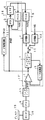
まず、図1を参照して第1の実施例を説明する。図1は、データスライス回路を用いたディスク再生装置の回路ブロック図である。このCDからデータを再生するディスク再生装置は、ディスク15をモータ制御回路(図示せず)及びモータ16によって、例えば、線速度一定(CLV)で回転させる。半導体レーザや光電変換素子などを内臓した光学式ピックアップ(PU)9によってディスク15から読み出されたデータは、電波信号として広帯域のヘッドアンプ10に供給される。このアンプ10は、電流信号を増幅し、電圧信号としての広帯域の信号(RF)に変換し、RF信号をデータスライス回路17に供給する。
データスライス回路17は、前記アンプ10から供給されるRF信号と基準電圧とを比較し、RF信号と基準電圧とに応じてデータ“0”とデータ“1”のうちの1つのデータを出力する比較器1と、クロック信号を分周し、カウント用のクロック信号を生成する分周器4と、比較器1から供給されるデータ“0”の期間とデータ“1”の期間に応じて、分周器4から供給されるカウント用のクロック信号をカウントし、これらの差分データを出力するアップタウンカウンタ2と、アップダウンカウンタ2から出力される差分データが供給され、この差分データをアナログ電圧に変換し、前記基準電圧として比較器1に供給するデジタル/アナログ変換器3とから構成されている。
【0015】
このRF信号は、比較器1の非反転入力端に供給され、基準電圧は、比較器の反転入力端に供給される。そして比較器1は、RF信号と基準電圧とを比較し、RF信号を“0”又は“1”の2値データに変換する。比較器1の出力端は、アップダウンカウンタ2に接続されている。アップダウンカウンタ2には、カウント用のクロック信号CKが供給されている。このアップダウンカウンタ2は、比較器1から出力されるデータ“0”の期間とデータ“1”の期間に応じて、クロック信号CKをカウントし、その期間の差分データを出力する。すなわち、アップダウンカウンタ2は、比較器1からデータ“0”が供給された場合、クロック信号CKをダウンカウントし、比較器1からデータ“1”が供給された場合、クロック信号CKをアップカウントする。したがって、このアップダウンカウンタ2からは、データ“0”の期間とデータ“1”の期間の差分データが出力される。この差分データはD/A変換器3においてアナログ電圧に変換する。このアナログ電圧は、前記基準電圧として、比較器1にフィードバックされる。このフィードバックにより、比較器2から出力されるデータ“0”の期間とデータ“1”の期間が等しくなるように制御される。このデータ“0”及びデータ“1”はEFM信号を構成する。
【0016】
データスライス回路17は、RF信号を2値化し、EFM信号などの2値化された信号をPLL回路18及びデータ処理回路11に供給する。
PLL回路18は、EFM信号が供給される位相比較器(PD)5と、位相比較器5の出力が供給される低域通過フィルタ(LPF)6と、低域通過フィルタ6の出力が入力され、出力が位相比較器5に供給される電圧制御発振器(VCO)7で構成される。
PLL回路18は、EFM信号に同期した第1のクロック信号PLCK1を生成する。この第1のクロック信号PLCK1がRF信号に同期しているとき、このクロック信号の周波数は、再生速度に比例している。PLL回路18を構成する低域通過フィルタ(LPF)6が出力する周波数制御信号は、電圧制御発振器(VCO)8に入力され、この周波数制御信号に基づいて第2のクロック信号(PLCK2)が生成される。したがって、この電圧制御発振器8は、クロック信号発生回路として用いられ、データスライス回路を構成する。第2のクロック信号PLCK2は、再生速度には追従しているが、EFM信号には非同期である。データスライス回路17のアップダウンカウンタ2に供給されるクロック信号CKは、第2のクロック信号PLCK2を分周器4で1/Nに分周して生成された信号である。
【0017】
すなわち、再生速度が速くなると、PLL回路が追従し、第1のクロック信号PLCK1の周波数は高くなる。それにともなって、第2のクロック信号PLCK2の周波数も高くなる。したがって、アップダウンカウンタ2のクロック信号CKも高くなるため、カウント結果の変化が速くなり、アップダウンカウンタ2の伝導利得が大きくなる。したがってフィードバックループにおいて、開ループ利得が大きくなり、制御帯域は高くなる。逆に、再生速度が遅くなると、第2のクロック信号PLCK2の周波数は低くなり、制御帯域は低くなる。このように、再生速度に合わせた最適な制御帯域を確保できる。
また、比較器1とアップダウンカウンタ2とD/A変換器3から構成されるデータスライス回路のフィードバックループと、第2のクロック信号とは同期していないのでデータスライス回路単体での帯域設計が容易にできる。
データ処理回路11は、EFM信号から同期信号を分離した後EFM復調し、パリティデータP、Qを含む32シンボルのデータ成分とサブコードデータ成分とに分離する。ついで、EFM復調されたデータは、データ処理回路11において、PLL回路18で生成された第2のクロック信号PLCK2により、メモリ(図示せず)へ書き込まれる。メモリから読み出されたデータは、誤り訂正された後16ビットのデジタルデータとしてデータ処理回路11から出力される。
【0018】
再生速度の可変は、システムコントローラ(図示せず)が行う。システムコントローラは、再生速度コントロール信号を生成する。この再生速度コントロール信号は、例えば、通常の再生速度(1倍速)又は基準速度の2倍の速度(2倍速)、・・・32倍の再生速度(32倍速)を指定する。この再生速度コントロール信号は、データ処理回路11、モータ制御回路(図示せず)に供給され、処理速度及びディスク再生速度を目的の速度に切り換える。再生速度コントロール信号は、データスライス回路17にも供給され、データスライス回路17は、この信号に応じて制御周波数帯域を再生速度に対応するように変化させている。
従来のディスク再生装置には、データ処理回路がメモリ(RAM)にデータを書き込む時にPLL回路から生成されたPLL系クロック信号を用い、メモリから読み出す時に水晶系の基準クロック信号を用いるもの(従来例1)とメモリから読み出す時にもPLL系クロック信号を用いるもの(従来例2)がある。従来例1は、再生速度が可変の場合に、線速度が規定速度となるまでの期間は安定してデータを再生できないので再生が中断される。これに対して、従来例2は、従来例1を改良したものであり、PLL系クロック信号が再生速度に同期している。このためピックアップが内周から外周に移動した時点で安定したデータを再生できるので、確実にデータを出力することができる。従ってアクセス後、データの出力を再開するまでの時間を従来例1より短縮できる。しかも従来例2のデータスライス回路は、PLL系クロック信号に応じて基準電圧の制御帯域を制御しているため再生速度に合わせた最適な制御帯域を確保することができる。
【0019】
前述のように従来例2ではクロック信号は再生速度に同期しており(同期クロック)、従来例1ではクロック信号は再生速度に同期していない(非同期クロック)。同期クロックの場合、クロック幅により分解能に制約が有り、クロック周波数がEFM信号より十分高い場合(クロック>>EFM)は分解能の問題は出ないが、高速再生化が著しくなると、クロック>>EFMの関係は維持できなくなる。非同期クロックの場合、帯域が再生レートに追従しないが、前記分解能の問題は生じない。これは、図5に示すように、同期クロックの場合、EFM信号の時間幅は、時間幅が大きくなるにしたがって、アップダウンカウンタのカウント結果の発生確率が段階的に大きくなる(特性線A)が、非同期クロックの場合、カウント結果の発生確率は、実際の時間幅に比例している(特性線B)ように、非同期クロックの場合は、分解能による制約は無い。図5は、縦軸がカウント結果の発生確率であり、横軸がEFM信号の実際の時間幅を示している。
本発明は、カウント結果の発生確率が実際の時間幅と一致するようにPLL系クロック信号を用いながらカウント結果をEFM信号の実際の時間幅に一致させることに特徴がある。
【0020】
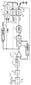
次に、図2を参照して第2の実施例を説明する。
図2は、データスライス回路を用いたディスク再生装置の回路ブロック図である。図1に示すディスク再生装置では、分周器4から供給される出力信号をアップダウンカウンタ2のクロック信号CKとして用いたが、この実施例では、分周器4に加えて、分周器13、スイッチ12をさらに有していることに特徴がある。すなわち、この実施例で用いるデータスライス回路17′は、前記アンプ10から供給されるRF信号と基準電圧とを比較し、RF信号と基準電圧とに応じてデータ“0”とデータ“1”のうちの1つのデータを出力する比較器1と、クロック信号を分周し、カウント用のクロック信号を生成する第1及び第2の分周器4、13と、比較器1から供給されるデータ“0”の期間とデータ“1”の期間に応じて、第1及び第2の分周器4又は13から供給されるカウント用のクロック信号をカウントし、これらの差分データを出力するアップタウンカウンタ2と、アップダウンカウンタ2から出力される差分データが供給され、この差分データをアナログ電圧に変換し、前記基準電圧として比較器1に供給するデジタル/アナログ変換器3とから構成されている。第1の分周器4は、前述したように、クロック信号生成回路から生成されるPLL系クロック信号PLCK2を1/Nに分周しクロック信号CKを生成する。
【0021】
そして、第2の分周器13は、水晶振動子によって発生された基準クロックに基づき、基準クロック生成回路から生成されるシステム基準クロック信号XCKを1/Mに分周し、周波数が固定された水晶系のクロック信号CKを生成する。スイッチ12は、第1の分周器4から出力されるクロック信号CK及び第2の分周器13から出力されるクロック信号CKのいずれか一方を選択し、アップダウンカウンタ2に供給する。スイッチ12を、PLL回路18のロック/アンロックに応じて、第1及び第2の分周器4、13のいずれか一方を選択するとする。スイッチ12は、PLL回路がロックしている場合は、第1の分周器4から出力されるPLL系クロック信号CKを選択し、ロックしていない場合は、第2の分周器13から出力される水晶系のクロック信号CKを選択する。水晶系クロック信号CKの周波数は、再生速度がその変化範囲の中心のとき、制御帯域が最適となる周波数に設定されている。したがって、なんらかの要因でPLL回路18引き込みが遅れた場合、データスライス回路の制御帯域が最適値から大きくずれることを防止できる。スイッチ12の切換え条件は、PLL回路18が完全にロック状態またはアンロック状態から若干ずれた範囲で切換えても良い。
【0022】
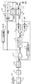
次ぎに、図3を参照して第3の実施例を説明する。
図3は、データスライス回路を用いたディスク再生装置の回路ブロック図である。図1に示すディスク再生装置は、PLL回路18から生成される周波数制御信号を電圧制御発振器(すなわち、クロック信号生成回路)8に供給しているが、この実施例のディスク再生装置は、PLL回路18と電圧制御発振器(クロック信号生成回路)8との間にスイッチ14を有していることに特徴がある。スイッチ14は、PLL回路18から出力される周波数制御信号及び基準電圧から出力される周波数制御信号のいずれか一方を選択して電圧制御発振器(クロック信号生成回路)8に供給する。なお、電圧制御発振器8は、データスライス回路を構成している。
【0023】
スイッチ14は、PLL回路18のロック/アンロックに応じて、PLL回路から出力される周波数制御信号及び基準電圧から出力される周波数制御信号のいずれか一方を選択するとする。スイッチ14は、PLL回路18がロックしている場合は、PLL回路18から出力される周波数制御信号を選択し、ロックしていない場合は、基準電圧から出力される周波数制御信号を選択する。したがって、なんらかの要因でPLL回路引き込みが遅れた場合、データスライス回路17″の制御帯域が最適値から大きくずれることを防止できる。
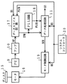
なお、この発明は、上記実施例に限定されるものではなく、発明の要旨を超えない範囲において、種々変形実施可能なことは勿論である。例えば、図4に示すように、図2に示すスイッチ12及び図3に示すスイッチ14を併用することができる。以上の様に構成すると、カウント用のクロック信号の選択の幅が広がるようになる。
【0024】
【発明の効果】
本発明は、以上の構成により、データスライス回路で用いるクロック信号が周波数的にはEFM信号の再生速度に連続的に追従し、位相がEFM信号と非同期となる。したがって再生速度によって再生性能が変化することを防止でき、かつデータスライス回路の帯域設計を単独で容易に行うことができる。また、何らかの要因でPLL回路引き込みが遅れた場合、データスライス回路の制御帯域が最適値から大きくくずれることを防止できる。
【図面の簡単な説明】
【図1】第1の実施例のディスク再生装置の回路ブロック図。
【図2】第2の実施例のディスク再生装置の回路ブロック図。
【図3】第3の実施例のディスク再生装置の回路ブロック図。
【図4】本発明のディスク再生装置の回路ブロック図。
【図5】本発明のアップダウンカウンタのカウント結果の発生確率のEFM信号の実際の時間幅依存性を示す特性図。
【図6】従来のディスク再生装置の回路ブロック図。
【符号の説明】
1・・・比較器、 2・・・アップダウンカウンタ、
3・・・D/A変換器、 4、13・・・分周器、
5・・・位相比較器、 6・・・低域通過フィルタ、
7、8・・・電圧制御発振器、 9・・・光学式ピックアップ、
10・・・ヘッドアンプ、 11・・・データ処理回路、
12、14・・・スイッチ、 15・・・ディスク、
16・・・モータ、 17、17′、17″・・・データスライス回路、
18・・・PLL回路。[0001]
BACKGROUND OF THE INVENTION
The present invention relates to an optical disk reproducing apparatus such as a compact disk (CD), and more particularly to a data slicing circuit of a reproducing apparatus capable of continuously varying a reproducing speed.
[0002]
[Prior art]
In the field of audio equipment, digital recording / playback systems are currently being developed. In order to perform recording and playback with high density and high fidelity, this system converts audio signals into digital signals using PCM (Pulse Code Modulation) technology, and records them on a recording medium such as a disk or magnetic tape. To do. In particular, a CD (Compact Disc) in which a bit string corresponding to digital data is formed on a disk having a diameter of 12 cm and this is optically read is currently most popular.
This CD stores digital data (main information data) obtained by converting an analog audio signal into 16-bit PCM. The digital data has 8 bits as one symbol and 24 symbols as one frame, and this frame is repeated to store the data. In this disc, a cross interleaved Reed-Solomon code (CIRC) is used as an error correction code.
[0003]
That is, 24-symbol digital data is supplied to a C2 sequence parity generation circuit to generate 4-symbol C2 sequence error correction parity data Q. The digital data and parity data Q are supplied to a C1 sequence parity generation circuit via an interleave circuit, and 4-symbol C1 sequence error correction parity data P is generated. 8-bit (1 symbol) subcode data is added to 32-symbol data consisting of 24-symbol digital data and 4-symbol parity data P and Q. This subcode data and 32 symbols of EFM modulation (Eight Four Modulation) are performed. A 3-bit margin bit is added between the modulated 14-bit symbols, and a 24-bit frame synchronization signal is added to the head. In this way, 588-bit data is recorded on the disc as one frame. In this case, since the bit clock is 4.32 MHz, recording is performed on the disc at 136 μsec (7.35 KHz) per frame. The subcode data is composed of 98 frames, and one subcode frame is recorded on the disc at 75 Hz (10.3 msec) per subcode frame.
[0004]
The disc reproducing apparatus for reproducing data from the CD rotates the CD with a constant linear velocity (CLV) by a motor control circuit and a motor. FIG. 6 is a circuit block diagram of a conventional disk reproducing apparatus. The
[0005]
The system controller 20 changes the reproduction speed. The system controller 20 generates a playback speed control signal (hereinafter referred to as HS). The HS signal designates, for example, a normal reproduction speed (referred to as 1 × speed) or a speed twice as high as a reference speed (referred to as 2 × speed). The HS signal is supplied to the
[0006]
[Problems to be solved by the invention]
The data slice circuit compares the RF signal input to the comparator with a reference voltage, and converts the RF signal into binary data or a binarized signal, for example, an EFM signal. The up / down counter counts the period of the binarized data “0” and the period of data “1”, and outputs the difference data during that period.
The counting clock of the up / down counter is a clock signal generated by a PLL circuit based on the EFM signal. This clock signal is synchronized with the data reproduction speed.
The difference data output from the up / down counter is supplied to a digital / analog converter. The digital / analog converter converts the difference data into an analog voltage and feeds it back to the comparator as the reference voltage. The comparator controls the period of data “0” to be equal to the period of data “1” by binarizing the RF signal with the fed back reference voltage.
[0007]
In this way, the data slice circuit feeds back the count result so that the period of data “0” and the period of data “1” are equal. If the bandwidth of the feedback loop is too low, the disk has scratches and the slice level cannot follow when the amplitude of the RF signal changes. On the other hand, if the band is too high, the slice level changes following the amplitude of the minute RF signal, so that the jitter of the EFM signal after slicing increases.
For the reasons described above, it is necessary to set the bandwidth of the data slice circuit. In the conventional data slice circuit, since the EFM signal and the clock signal input to the up / down counter are synchronized, it is difficult to design a band as a single data slice.
The present invention solves such a problem, and makes the frequency of the clock signal input to the up / down counter continuously follow the reproduction rate of the EFM signal, and the phase is asynchronous to the EFM signal. The present invention intends to provide a disc reproducing apparatus.
[0008]
[Means for Solving the Problems]
The disc reproducing apparatus of the present invention optically reads data recorded on a disc and converts it into an electrical signal, an amplifier for amplifying an electrical signal supplied from the photoelectric conversion unit, and a supply from the amplifier A data slice circuit that binarizes the electrical signal to be generated and generates a binarized signal such as an EFM signal, and a data slice circuit corresponding to a change in the data reproduction speed based on the EFM signal supplied from the data slice circuit. A PLL circuit that generates a clock signal of 1 and a data processing circuit that demodulates a binarized signal such as the EFM signal supplied from the data slice circuit and reproduces data, the data slice circuit comprising: Generating a second clock signal that is asynchronous with the EFM signal based on the signal supplied from the PLL circuit And comparing the electrical signal supplied from the photoelectric conversion means with a reference voltage, and selecting one of data “0” and data “1” according to the electrical signal and the reference voltage. A comparator for outputting; an up / down counter for detecting difference data between a period of data “0” and a period of data “1” supplied from the comparator based on the second clock signal; A first feature is that it includes a digital / analog converter that is supplied with the differential data output from the counter, converts the differential data into an analog voltage, and supplies the analog voltage to the comparator as the reference voltage.
[0009]
Further, the disk reproducing apparatus of the present invention includes a photoelectric conversion unit that optically reads data recorded on a disk and converts the data into an electric signal, an amplifier that amplifies the electric signal supplied from the photoelectric conversion unit, and the amplifier A data slice circuit that binarizes an electric signal supplied from the data slicer to generate a binarized signal, and a change in data reproduction speed based on the binarized signal supplied from the data slice circuit A PLL circuit that generates the first clock signal and the frequency control signal, a reference clock generation circuit that generates a reference clock signal based on the reference clock generated from the fixed frequency oscillation circuit, and the data slice circuit. A data processing circuit for demodulating the binarized signal and reproducing data, wherein the data slicing circuit includes the frequency control circuit. And a clock signal generation circuit that generates a second clock signal that is asynchronous with the binarized signal, and divides the second clock signal output from the clock signal generation circuit A first frequency divider that generates a clock signal for counting; and a second frequency divider that divides the reference clock output from the reference clock generation circuit and generates a clock signal for counting. A switch that selects one of the clock signals for counting output from the first and second frequency dividers, the electrical signal supplied from the photoelectric conversion means, and a reference voltage, and A comparator that outputs one of data “0” and data “1” in accordance with the electrical signal and the reference voltage; a period of data “0” supplied from the comparator; and data “1” According to period The up / down counter that counts the clock signal supplied from the switch and outputs the difference data, and the difference data output from the up / down counter is supplied, and the difference data is converted into an analog voltage. A second feature is that it has a digital / analog converter to be supplied to the comparator as a reference voltage.
[0010]
Further, the disk reproducing apparatus of the present invention includes a photoelectric conversion unit that optically reads data recorded on a disk and converts the data into an electric signal, an amplifier that amplifies the electric signal supplied from the photoelectric conversion unit, and the amplifier A data slice circuit that binarizes an electric signal supplied from the data slicer to generate a binarized signal, and a change in data reproduction speed based on the binarized signal supplied from the data slice circuit A PLL circuit that generates a first clock signal and a frequency control signal, a reference voltage generation circuit that generates a reference frequency control signal based on a reference voltage, a frequency control signal generated from the PLL circuit, and the reference voltage generation A switch for selecting one of the reference frequency control signals generated from the circuit, and the data slice circuit according to the second clock signal. A data processing circuit for demodulating the supplied binarized signal and reproducing the data, wherein the data slicing circuit is based on the frequency control signal supplied from the switch. A clock signal generation circuit that generates a second clock signal that is asynchronous with the reference signal, and compares the electrical signal supplied from the amplifier with a reference voltage. A comparator that outputs one of the data “0” and data “1”, a frequency divider that divides the second clock signal to generate a clock signal for counting, and a comparator that is supplied from the comparator An up-counter counter that counts the clock signals supplied from the frequency divider and outputs the difference data according to the data “0” period and the data “1” period A digital / analog converter that is supplied with the differential data output from the up / down counter, converts the differential data into an analog voltage, and supplies the analog voltage to the comparator as the reference voltage; And
[0011]
The data slicing circuit of the present invention compares an electric signal supplied from an amplifier that amplifies an electric signal supplied from the photoelectric conversion means with a reference voltage, and sets data “0” according to the electric signal and the reference voltage. A clock that continuously follows the frequency ratio between the comparator that outputs one of the data “1” and the output frequency of the comparator to be constant, and generates a clock having an asynchronous phase. A signal generation circuit, a frequency divider for dividing the output clock of the clock signal generation circuit, and the counting clock according to a period of data “0” and a period of data “1” supplied from the comparator. An up / down counter that counts a signal and outputs the difference data, and the difference data output from the up / down counter are supplied. Conversion, the first comprising the digital / analog converter to be supplied to the comparator as the reference voltage.
[0012]
The data slicing circuit according to the present invention includes a clock signal generating circuit that continuously follows a frequency ratio with respect to a frequency of the output of the comparator to generate a clock having an asynchronous phase, and the clock A first divider that divides the output clock of the signal generation circuit; a second divider that divides the reference clock signal generated from the reference clock generation circuit and generates a clock signal for counting; A switch for selecting one of the clock signals for counting output from the first and second frequency dividers, the electric signal supplied from the photoelectric conversion means and a reference voltage are compared, and the electric A comparator that outputs one of data “0” and data “1” in accordance with the signal and the reference voltage; a period of data “0” and a period of data “1” supplied from the comparator; In response to the The up / down counter that counts the clock signal supplied from the switch and outputs the difference data, and the difference data output from the up / down counter is supplied, and the difference data is converted into an analog voltage. A second feature is that a digital / analog converter is provided as a reference voltage to the comparator.
[0013]
The data slicing circuit binarizes the electrical signal supplied from the photoelectric conversion means, and generates a binarized signal such as an EFM signal. A frequency control signal is generated by the PLL circuit based on the EFM signal supplied from the data slice circuit, and this frequency control signal is supplied to the clock signal generation circuit to generate a clock signal for the up / down counter. According to the present invention, the frequency of the clock for the up / down counter continuously follows the reproduction rate of the EFM signal, and the phase is asynchronous with the EFM signal. Therefore, the control band of the reference voltage for slicing the RF signal generated using the difference data output from the up / down counter can be continuously changed according to the reproduction speed, and the data slice The band design of the circuit can be easily performed separately from the PLL circuit.
[0014]
DETAILED DESCRIPTION OF THE INVENTION
Hereinafter, embodiments of the present invention will be described with reference to the drawings.
First, a first embodiment will be described with reference to FIG. FIG. 1 is a circuit block diagram of a disk reproducing apparatus using a data slice circuit. In the disk reproducing apparatus for reproducing data from the CD, the
The
[0015]
This RF signal is supplied to the non-inverting input terminal of the
[0016]
The
The
The
[0017]
That is, when the reproduction speed increases, the PLL circuit follows and the frequency of the first clock signal PLCK1 increases. Along with this, the frequency of the second clock signal PLCK2 also increases. Therefore, since the clock signal CK of the up / down
In addition, since the feedback loop of the data slice circuit composed of the
The
[0018]
The system controller (not shown) changes the reproduction speed. The system controller generates a playback speed control signal. This playback speed control signal designates, for example, a normal playback speed (1 × speed), a speed twice the reference speed (2 × speed),... 32 times a playback speed (32 × speed). This playback speed control signal is supplied to the
A conventional disk reproducing apparatus uses a PLL clock signal generated from a PLL circuit when a data processing circuit writes data to a memory (RAM), and uses a crystal reference clock signal when reading from the memory (conventional example) 1) and a method using a PLL clock signal when reading from the memory (conventional example 2). In the conventional example 1, when the reproduction speed is variable, the reproduction is interrupted because the data cannot be stably reproduced during the period until the linear velocity reaches the specified speed. On the other hand, Conventional Example 2 is an improvement of Conventional Example 1, and the PLL clock signal is synchronized with the reproduction speed. For this reason, stable data can be reproduced when the pickup moves from the inner periphery to the outer periphery, so that the data can be reliably output. Therefore, it is possible to shorten the time until the data output is restarted after the access compared to the conventional example 1. In addition, since the data slice circuit of Conventional Example 2 controls the control band of the reference voltage in accordance with the PLL clock signal, it is possible to secure an optimal control band that matches the reproduction speed.
[0019]
As described above, in the conventional example 2, the clock signal is synchronized with the reproduction speed (synchronous clock), and in the conventional example 1, the clock signal is not synchronized with the reproduction speed (asynchronous clock). In the case of a synchronous clock, the resolution is limited by the clock width, and when the clock frequency is sufficiently higher than the EFM signal (clock >> EFM), there is no problem of resolution, but when high-speed reproduction becomes significant, the clock >> EFM The relationship cannot be maintained. In the case of an asynchronous clock, the band does not follow the reproduction rate, but the resolution problem does not occur. As shown in FIG. 5, in the case of a synchronous clock, the time width of the EFM signal increases stepwise as the time width of the EFM signal increases (characteristic line A). However, in the case of an asynchronous clock, the probability of occurrence of the count result is proportional to the actual time width (characteristic line B). In FIG. 5, the vertical axis represents the occurrence probability of the count result, and the horizontal axis represents the actual time width of the EFM signal.
The present invention is characterized in that the count result matches the actual time width of the EFM signal while using the PLL clock signal so that the occurrence probability of the count result matches the actual time width.
[0020]
Next, a second embodiment will be described with reference to FIG.
FIG. 2 is a circuit block diagram of a disk reproducing apparatus using a data slice circuit. In the disc reproducing apparatus shown in FIG. 1, the output signal supplied from the
[0021]
The
[0022]
Next, a third embodiment will be described with reference to FIG.
FIG. 3 is a circuit block diagram of a disk reproducing apparatus using a data slice circuit. The disk reproducing apparatus shown in FIG. 1 supplies the frequency control signal generated from the
[0023]
It is assumed that the
In addition, this invention is not limited to the said Example, Of course, in the range which does not exceed the summary of invention, various deformation | transformation implementation is possible. For example, as shown in FIG. 4, the
[0024]
【The invention's effect】
According to the present invention, the clock signal used in the data slicing circuit continuously follows the reproduction speed of the EFM signal in terms of frequency, and the phase is asynchronous with the EFM signal. Therefore, the reproduction performance can be prevented from changing depending on the reproduction speed, and the bandwidth design of the data slice circuit can be easily performed independently. Further, when the pull-in of the PLL circuit is delayed for some reason, the control band of the data slice circuit can be prevented from being greatly deviated from the optimum value.
[Brief description of the drawings]
FIG. 1 is a circuit block diagram of a disk reproducing apparatus according to a first embodiment.
FIG. 2 is a circuit block diagram of a disc reproducing apparatus according to a second embodiment.
FIG. 3 is a circuit block diagram of a disk reproducing apparatus according to a third embodiment.
FIG. 4 is a circuit block diagram of the disk reproducing apparatus of the present invention.
FIG. 5 is a characteristic diagram showing the actual time width dependence of the EFM signal of the occurrence probability of the count result of the up / down counter according to the present invention.
FIG. 6 is a circuit block diagram of a conventional disk reproducing apparatus.
[Explanation of symbols]
1 ... comparator, 2 ... up / down counter,
3 ... D / A converter, 4, 13 ... frequency divider,
5 ... Phase comparator, 6 ... Low pass filter,
7, 8 ... Voltage controlled oscillator, 9 ... Optical pickup,
10 ... head amplifier, 11 ... data processing circuit,
12, 14 ... switch, 15 ... disk,
16 ... motor, 17, 17 ', 17 "... data slice circuit,
18: PLL circuit.
Claims (5)
前記光電変換手段から供給される電気信号を増幅する増幅器と、
前記増幅器から供給される電気信号から2値化された信号を生成するデータスライス回路と、
前記データスライス回路から供給される2値化された信号に基づき、データの再生速度の変化に応じた第1のクロック信号及び周波数制御信号を生成するPLL回路と、
前記データスライス回路から供給される前記2値化された信号を復調し、データを再生するデータ処理回路とを備え、
前記データスライス回路は、前記周波数制御信号に基づいて前記2値化された信号とは非同期である第2のクロック信号を生成するクロック信号生成回路を有し、前記増幅器から供給される前記電気信号と基準電圧とを比較し、前記電気信号と基準電圧とに応じてデータ“0”とデータ“1”のうちの1つのデータを出力する比較器と、前記第2のクロック信号を分周し、カウント用のクロック信号を生成する分周器と、前記比較器から供給されるデータ“0”の期間とデータ “1”の期間に応じて、前記分周器から供給されるカウント用のクロック信号をカウントし、データ“0”の期間とデータ“1”の期間の差分データを出力するアップダウンカウンタと、前記アップダウンカウンタから出力される前記差分データが供給され、この前記差分データをアナログ電圧に変換し、前記基準電圧として前記比較器に供給するデジタル/アナログ変換器とを有することを特徴とするディスク再生装置。Photoelectric conversion means for optically reading data recorded on the disk and converting it into an electrical signal;
An amplifier for amplifying an electric signal supplied from the photoelectric conversion means;
A data slicing circuit for generating a binarized signal from the electric signal supplied from the amplifier;
A PLL circuit that generates a first clock signal and a frequency control signal according to a change in a data reproduction speed based on a binarized signal supplied from the data slice circuit;
A data processing circuit for demodulating the binarized signal supplied from the data slicing circuit and reproducing data;
The data slicing circuit includes a clock signal generation circuit that generates a second clock signal that is asynchronous with the binarized signal based on the frequency control signal, and the electrical signal supplied from the amplifier And a reference voltage, and a comparator that outputs one of data “0” and data “1” according to the electrical signal and the reference voltage, and the second clock signal is divided. A frequency divider for generating a clock signal for counting, and a clock for counting supplied from the frequency divider in accordance with a period of data “0” and a period of data “1” supplied from the comparator counting the signals, the up-down counter which outputs the differential data of the period of the data "0" periods and "1" data, the differential data output from the up-down counter is supplied, the pre And a digital / analog converter for converting the difference data into an analog voltage and supplying the analog voltage to the comparator as the reference voltage.
前記光電変換手段から供給される電気信号を増幅する増幅器と、
前記増幅器から供給される電気信号から2値化された信号を生成するデータスライス回路と、
前記データスライス回路から供給される2値化された信号に基づき、データの再生速度の変化に応じた第1のクロック信号及び周波数制御信号を生成するPLL回路と、
固定周波数発振回路から生成された基準クロックに基づいて基準クロック信号を生成する基準クロック生成回路と、
前記データスライス回路から供給される前記2値化された信号を復調し、データを再生するデータ処理回路とを備え、
前記データスライス回路は、前記周波数制御信号に基づいて前記2値化された信号とは非同期である第2のクロック信号を生成するクロック信号生成回路を有し、前記クロック信号生成回路から出力される前記第2のクロック信号を分周し、カウント用のクロック信号を生成する第1の分周器と、前記基準クロック生成回路から出力される前記基準クロック信号を分周し、カウント用のクロック信号を生成する第2の分周器と、前記第1及び第2の分周器から出力されるカウント用のクロック信号のうち1つを選択するスイッチと、前記光電変換手段から供給される前記電気信号と基準電圧とを比較し、前記電気信号と基準電圧とに応じてデータ“0”とデータ“1”のうちの1つのデータを出力する比較器と、前記比較器から供給されるデータ“0”の期間とデータ“1”の期間に応じて、前記スイッチから供給されるクロック信号をカウントし、データ“0”の期間とデータ “1”の期間の差分データを出力するアップダウンカウンタと、前記アップダウンカウンタから出力される前記差分データが供給され、この前記差分データをアナログ電圧に変換し、前記基準電圧として前記比較器に供給するデジタル/アナログ変換器とを有することを特徴とするディスク再生装置。Photoelectric conversion means for optically reading data recorded on the disk and converting it into an electrical signal;
An amplifier for amplifying an electric signal supplied from the photoelectric conversion means;
A data slicing circuit for generating a binarized signal from the electric signal supplied from the amplifier;
A PLL circuit that generates a first clock signal and a frequency control signal according to a change in a data reproduction speed based on a binarized signal supplied from the data slice circuit;
A reference clock generation circuit that generates a reference clock signal based on a reference clock generated from a fixed frequency oscillation circuit;
A data processing circuit for demodulating the binarized signal supplied from the data slicing circuit and reproducing data;
The data slice circuit has a clock signal generation circuit that generates a second clock signal that is asynchronous with the binarized signal based on the frequency control signal, and is output from the clock signal generation circuit A first frequency divider that divides the second clock signal and generates a clock signal for counting, and the reference clock signal that is output from the reference clock generation circuit divides the clock signal for counting. A second frequency divider for generating a signal, a switch for selecting one of the clock signals for counting output from the first and second frequency dividers, and the electric power supplied from the photoelectric conversion means A comparator that compares the signal with a reference voltage and outputs one of data “0” and data “1” in accordance with the electrical signal and the reference voltage; and a data supplied from the comparator Depending on the duration of the period and the data "1" of the data "0", the up-down counts the clock signal supplied from the switch to output the difference data period of the data "0" period and data "1" wherein a counter, wherein is supplied the difference data output from the up-down counter, that the said differential data into an analog voltage, and a digital / analog converter to be supplied to the comparator as the reference voltage Disc playback device.
前記光電変換手段から供給される電気信号を増幅する増幅器と、
前記増幅器から供給される電気信号から2値化された信号を生成するデータスライス回路と、
前記データスライス回路から供給される2値化された信号に基づき、データの再生速度の変化に応じた第1のクロック信号及び周波数制御信号を生成するPLL回路と、
基準電圧に基づいて基準周波数制御信号を生成する基準電圧生成回路と、
前記PLL回路から生成された周波数制御信号と前記基準電圧生成回路から生成された基準周波数制御信号のうち1つを選択するスイッチと、
前記データスライス回路から供給される前記2値化された信号を復調し、データを再生するデータ処理回路とを備え、
前記データスライス回路は、前記スイッチから供給される周波数制御信号に基づいて前記2値化された信号とは非同期である第2のクロック信号を生成するクロック信号生成回路を有し、前記増幅器から供給される前記電気信号と基準電圧とを比較し、前記電気信号と基準電圧とに応じてデータ“0”とデータ“1”のうちの1つのデータを出力する比較器と、前記第2のクロック信号を分周し、カウント用のクロック信号を生成する分周器と、前記比較器から供給されるデータ“0”の期間とデータ“1”の期間に応じて、前記分周器から供給されるカウント用のクロック信号をカウントし、データ“0”の期間とデータ“1”の期間の差分データを出力するアップダウンカウンタと、前記アップダウンカウンタから出力される前記差分データが供給され、この前記差分データをアナログ電圧に変換し前記基準電圧として前記比較器に供給するデジタル/アナログ変換器とを有することを特徴とするディスク再生装置。Photoelectric conversion means for optically reading data recorded on the disk and converting it into an electrical signal;
An amplifier for amplifying an electric signal supplied from the photoelectric conversion means;
A data slicing circuit for generating a binarized signal from the electric signal supplied from the amplifier;
A PLL circuit that generates a first clock signal and a frequency control signal according to a change in a data reproduction speed based on a binarized signal supplied from the data slice circuit;
A reference voltage generation circuit that generates a reference frequency control signal based on the reference voltage;
A switch for selecting one of a frequency control signal generated from the PLL circuit and a reference frequency control signal generated from the reference voltage generation circuit;
A data processing circuit for demodulating the binarized signal supplied from the data slicing circuit and reproducing data;
The data slicing circuit has a clock signal generation circuit that generates a second clock signal that is asynchronous with the binarized signal based on a frequency control signal supplied from the switch, and is supplied from the amplifier A comparator that compares the electrical signal with a reference voltage and outputs one of data “0” and data “1” in accordance with the electrical signal and the reference voltage; and the second clock A frequency divider that divides the signal and generates a clock signal for counting, and is supplied from the frequency divider according to a period of data “0” and a period of data “1” supplied from the comparator. counting the clock signal for counting that, the up-down counter which outputs the differential data of the period of the data "0" period and data "1", the difference de output from the up-down counter Data is supplied, the disk reproducing apparatus characterized by having a the said differential data into an analog voltage the digital / analog converter to be supplied to the comparator as the reference voltage.
前記比較器の出力の周波数との周波数比が一定になるように連続的に追従し、かつ位相が非同期のクロック信号を生成するクロック信号生成回路と、
前記クロック信号生成回路の出力クロックを分周する分周器と、
前記比較器から供給されるデータ“0”の期間とデータ“1”の期間に応じて前記カウント用クロック信号をカウントし、データ“0”の期間とデータ“1”の期間の差分データを出力するアップダウンカウンタと、前記アップダウンカウンタから出力される前記差分データが供給され、この前記差分データをアナログ電圧に変換し、前記基準電圧として前記比較器に供給するデジタル/アナログ変換器とを備えたことを特徴とするデータスライス回路。An electric signal supplied from an amplifier for amplifying an electric signal supplied from a photoelectric conversion means for optically reading data recorded on the disk and converting it into an electric signal is compared with the reference voltage, and the electric signal and the reference voltage are compared. A comparator that outputs one of data “0” and data “1” according to
A clock signal generating circuit that continuously follows the frequency ratio with the output frequency of the comparator to be constant and generates a clock signal having an asynchronous phase;
A frequency divider for dividing the output clock of the clock signal generation circuit;
The counting clock signal is counted in accordance with the data “0” period and the data “1” period supplied from the comparator, and difference data between the data “0” period and the data “1” period is output. and up-down counter for the said difference data output from the up-down counter is supplied, converts the said difference data to an analog voltage, and a digital / analog converter to be supplied to the comparator as the reference voltage A data slice circuit characterized by that.
前記比較器の出力の周波数との周波数比が一定になるように連続的に追従し、かつ位相が非同期のクロックを生成するクロック信号生成回路と、
前記クロック信号生成回路の出力クロックを分周する第1の分周器と、
基準クロック信号生成回路から生成される基準クロック信号を分周し、カウント用のクロック信号を生成する第2の分周器と、
前記第1及び第2の分周器から出力されるカウント用のクロック信号のうち1つを選択するスイッチと、
前記光電変換手段から供給される前記電気信号と基準電圧とを比較し、前記電気信号と基準電圧とに応じてデータ“0”とデータ“1”のうちの1つのデータを出力する比較器と、
前記比較器から供給されるデータ“0”の期間とデータ“1”の期間に応じて前記スイッチから供給されるクロック信号をカウントし、データ“0”の期間とデータ“1”の期間の差分データを出力するアップダウンカウンタと、前記アップダウンカウンタから出力される前記差分データが供給され、この前記差分データをアナログ電圧に変換し、前記基準電圧として前記比較器に供給するデジタル/アナログ変換器とを備えたことを特徴とするデータスライス回路。 An electric signal supplied from an amplifier for amplifying an electric signal supplied from a photoelectric conversion means for optically reading data recorded on the disk and converting it into an electric signal is compared with the reference voltage, and the electric signal and the reference voltage are compared. A comparator that outputs one of data “0” and data “1” according to
A clock signal generation circuit that continuously follows the frequency ratio with the output frequency of the comparator to be constant and generates a clock having an asynchronous phase;
A first divider for dividing the output clock of the clock signal generation circuit;
A second frequency divider that divides the reference clock signal generated from the reference clock signal generation circuit and generates a clock signal for counting;
A switch for selecting one of the clock signals for counting output from the first and second frequency dividers;
A comparator that compares the electrical signal supplied from the photoelectric conversion means with a reference voltage and outputs one of data “0” and data “1” in accordance with the electrical signal and the reference voltage; ,
The clock signal supplied from the switch is counted according to the data “0” period and the data “1” period supplied from the comparator, and the difference between the data “0” period and the data “1” period is counted. and up-down counter that outputs data, the differential data output from the up-down counter is supplied, converts the said difference data to an analog voltage, a digital / analog converter to be supplied to the comparator as the reference voltage And a data slicing circuit.
Priority Applications (4)
| Application Number | Priority Date | Filing Date | Title |
|---|---|---|---|
| JP18573297A JP3607048B2 (en) | 1997-06-26 | 1997-06-26 | Disc reproducing apparatus and data slicing circuit |
| TW087110256A TW393763B (en) | 1997-06-26 | 1998-06-25 | Disk reproduction device and data slicing circuit |
| US09/105,170 US6157603A (en) | 1997-06-26 | 1998-06-26 | Disk reproduction apparatus capable of continuously varying a reproduction speed |
| KR1019980024361A KR100276199B1 (en) | 1997-06-26 | 1998-06-26 | Disk reproducing device and data slicing circuit |
Applications Claiming Priority (1)
| Application Number | Priority Date | Filing Date | Title |
|---|---|---|---|
| JP18573297A JP3607048B2 (en) | 1997-06-26 | 1997-06-26 | Disc reproducing apparatus and data slicing circuit |
Publications (2)
| Publication Number | Publication Date |
|---|---|
| JPH1116280A JPH1116280A (en) | 1999-01-22 |
| JP3607048B2 true JP3607048B2 (en) | 2005-01-05 |
Family
ID=16175899
Family Applications (1)
| Application Number | Title | Priority Date | Filing Date |
|---|---|---|---|
| JP18573297A Expired - Fee Related JP3607048B2 (en) | 1997-06-26 | 1997-06-26 | Disc reproducing apparatus and data slicing circuit |
Country Status (4)
| Country | Link |
|---|---|
| US (1) | US6157603A (en) |
| JP (1) | JP3607048B2 (en) |
| KR (1) | KR100276199B1 (en) |
| TW (1) | TW393763B (en) |
Families Citing this family (10)
| Publication number | Priority date | Publication date | Assignee | Title |
|---|---|---|---|---|
| JP4395956B2 (en) * | 1999-03-18 | 2010-01-13 | アイシン精機株式会社 | Motor rotation pulse generation circuit for DC motor |
| WO2001022412A1 (en) * | 1999-09-20 | 2001-03-29 | Hitachi, Ltd. | Information recording/reproducing apparatus |
| US6954410B2 (en) * | 2000-01-20 | 2005-10-11 | Hitachi, Ltd. | Information recording and reproducing apparatus for updating the waveform of a laser based on position information |
| TW465194B (en) | 2000-10-17 | 2001-11-21 | Mediatek Inc | Data dividing circuit and method for diving data |
| DE10061530A1 (en) * | 2000-12-11 | 2002-04-04 | Infineon Technologies Ag | Frequency measurement unit uses counter feedback not affected by phase offset |
| JP3993818B2 (en) * | 2002-12-16 | 2007-10-17 | 松下電器産業株式会社 | Playback signal processing device |
| KR100614344B1 (en) * | 2004-08-18 | 2006-08-21 | 주식회사 히타치엘지 데이터 스토리지 코리아 | Method and apparatus for eliminating errors in seeking operation on a recording medium |
| TWI276065B (en) * | 2004-11-01 | 2007-03-11 | Lite On It Corp | CD reading method |
| JP2006279849A (en) * | 2005-03-30 | 2006-10-12 | Sanyo Electric Co Ltd | Voltage-holding circuit and clock synchronization circuit |
| US8355302B1 (en) | 2006-05-11 | 2013-01-15 | Marvell International Ltd. | Offset loop for wobble |
Family Cites Families (5)
| Publication number | Priority date | Publication date | Assignee | Title |
|---|---|---|---|---|
| JPH0756730B2 (en) * | 1989-12-28 | 1995-06-14 | パイオニア株式会社 | Spindle servo circuit |
| DE69426636T2 (en) * | 1993-08-14 | 2001-06-21 | Toshiba Kawasaki Kk | Playback device and signal processing circuit for data recorded on a disc |
| JP2885650B2 (en) * | 1993-11-11 | 1999-04-26 | 株式会社東芝 | Disc playback device |
| JP4319259B2 (en) * | 1996-07-02 | 2009-08-26 | 株式会社東芝 | Active wide-range PLL device, phase-locked loop method, and disk playback device |
| TW341415U (en) * | 1997-04-08 | 1998-09-21 | United Microelectronics Corp | A digital data cutting circuit |
-
1997
- 1997-06-26 JP JP18573297A patent/JP3607048B2/en not_active Expired - Fee Related
-
1998
- 1998-06-25 TW TW087110256A patent/TW393763B/en not_active IP Right Cessation
- 1998-06-26 US US09/105,170 patent/US6157603A/en not_active Expired - Lifetime
- 1998-06-26 KR KR1019980024361A patent/KR100276199B1/en not_active IP Right Cessation
Also Published As
| Publication number | Publication date |
|---|---|
| KR19990007375A (en) | 1999-01-25 |
| US6157603A (en) | 2000-12-05 |
| KR100276199B1 (en) | 2000-12-15 |
| JPH1116280A (en) | 1999-01-22 |
| TW393763B (en) | 2000-06-11 |
Similar Documents
| Publication | Publication Date | Title |
|---|---|---|
| JP2885650B2 (en) | Disc playback device | |
| US4495474A (en) | PLL Control circuit for recovery of data from audio disk | |
| JP2926900B2 (en) | Disc playback device | |
| JP3607048B2 (en) | Disc reproducing apparatus and data slicing circuit | |
| JP3433021B2 (en) | PLL circuit | |
| JPH06124546A (en) | Information reproducing device | |
| JPH03212860A (en) | Pll circuit for clock generation | |
| JP3492647B2 (en) | Information recording method and apparatus | |
| JP2661062B2 (en) | Data playback device | |
| KR100422600B1 (en) | Playback apparatus having spindle servo controller for controlling constant velocity | |
| JPS59111423A (en) | Protecting device of pll circuit for synchronizing signal regeneration | |
| JPH0896516A (en) | Clock generating device | |
| JP3456359B2 (en) | Digital signal reproduction device | |
| JP2876601B2 (en) | Synchronization detection device for digital disk playback device | |
| WO2004095454A1 (en) | Reproduction apparatus and method | |
| JP2876602B2 (en) | Synchronization detection device for digital disk playback device | |
| JP3386506B2 (en) | Information recording / reproducing device | |
| JPS60195778A (en) | Demodulator of digital information | |
| JPS60171680A (en) | Digital audio disk reproducing device | |
| JPH0450673B2 (en) | ||
| JPS59152513A (en) | Digital data producer | |
| JPH1125588A (en) | Disk motor control circuit and disk reproducing device using the same | |
| JPH07134873A (en) | Disc reproducer and signal processing circuit | |
| JPS59152512A (en) | Digital data producer | |
| JPS6275972A (en) | Disk motor control circuit |
Legal Events
| Date | Code | Title | Description |
|---|---|---|---|
| A131 | Notification of reasons for refusal |
Free format text: JAPANESE INTERMEDIATE CODE: A131 Effective date: 20040206 |
|
| A131 | Notification of reasons for refusal |
Free format text: JAPANESE INTERMEDIATE CODE: A131 Effective date: 20040511 |
|
| A521 | Request for written amendment filed |
Free format text: JAPANESE INTERMEDIATE CODE: A523 Effective date: 20040712 |
|
| TRDD | Decision of grant or rejection written | ||
| A01 | Written decision to grant a patent or to grant a registration (utility model) |
Free format text: JAPANESE INTERMEDIATE CODE: A01 Effective date: 20041001 |
|
| A61 | First payment of annual fees (during grant procedure) |
Free format text: JAPANESE INTERMEDIATE CODE: A61 Effective date: 20041006 |
|
| FPAY | Renewal fee payment (event date is renewal date of database) |
Free format text: PAYMENT UNTIL: 20081015 Year of fee payment: 4 |
|
| FPAY | Renewal fee payment (event date is renewal date of database) |
Free format text: PAYMENT UNTIL: 20081015 Year of fee payment: 4 |
|
| FPAY | Renewal fee payment (event date is renewal date of database) |
Free format text: PAYMENT UNTIL: 20091015 Year of fee payment: 5 |
|
| FPAY | Renewal fee payment (event date is renewal date of database) |
Free format text: PAYMENT UNTIL: 20101015 Year of fee payment: 6 |
|
| FPAY | Renewal fee payment (event date is renewal date of database) |
Free format text: PAYMENT UNTIL: 20111015 Year of fee payment: 7 |
|
| FPAY | Renewal fee payment (event date is renewal date of database) |
Free format text: PAYMENT UNTIL: 20111015 Year of fee payment: 7 |
|
| FPAY | Renewal fee payment (event date is renewal date of database) |
Free format text: PAYMENT UNTIL: 20121015 Year of fee payment: 8 |
|
| FPAY | Renewal fee payment (event date is renewal date of database) |
Free format text: PAYMENT UNTIL: 20131015 Year of fee payment: 9 |
|
| LAPS | Cancellation because of no payment of annual fees |