JP3604885B2 - Image processing apparatus, data processing method for image processing apparatus, and storage medium storing computer-readable program - Google Patents
Image processing apparatus, data processing method for image processing apparatus, and storage medium storing computer-readable program Download PDFInfo
- Publication number
- JP3604885B2 JP3604885B2 JP30199797A JP30199797A JP3604885B2 JP 3604885 B2 JP3604885 B2 JP 3604885B2 JP 30199797 A JP30199797 A JP 30199797A JP 30199797 A JP30199797 A JP 30199797A JP 3604885 B2 JP3604885 B2 JP 3604885B2
- Authority
- JP
- Japan
- Prior art keywords
- image
- unit
- storage
- image information
- output
- Prior art date
- Legal status (The legal status is an assumption and is not a legal conclusion. Google has not performed a legal analysis and makes no representation as to the accuracy of the status listed.)
- Expired - Fee Related
Links
Images


Landscapes
- Record Information Processing For Printing (AREA)
- Facsimiles In General (AREA)
- Storing Facsimile Image Data (AREA)
Description
【0001】
【発明の属する技術分野】
本発明は、コピー,プリント,ファクシミリなど多様な画像入出力機能を備えた画像処理装置および画像処理装置のデータ処理方法およびコンピュータが読み出し可能なプログラムを格納した記憶媒体に関するものである。
【0002】
【従来の技術】
従来、ページ記述言語で記述したデータ(以下、PDLデータともいう)を入力し、画像を形成して出力する画像処理装置において、スキャナや通信手段を備え、コピー機能,プリント機能,ファクシミリ機能など、一つの画像形成手段を使用して複数の画像出力機能を実現する装置が提案されている。
【0003】
また、プリンタから印刷可能に展開した画像データをそのままプリントアウトするだけでなく、ファクシミリ送信したり、画像記憶装置に転送し、後でユーザが任意にプリントアウトするといった様々な複合機能処理も提案されている。
【0004】
【発明が解決しようとする課題】
しかしながら、このような構成において、例えばコピー中に紙詰まり等が発生しプリンタが使用できないような場合、PDLデータを展開する機能も、展開した画像をプリントアウトできないため、紙詰まりが解除されたプリンタが使用できるようになるまで、やむをえず展開動作を停止したり、オフラインに移行しホストからのデータを受け付けないようにしていた。
【0005】
このように、複数の画像出力機能を一台の装置で実現できる一方で、ある機能においてプリンタに障害が発生してしまうと、その他のプリンタを使用する機能もプリンタの障害が取り除かれなければ、機能処理を継続することができなかった。
【0006】
中でも、特にコピー機能やファクシミリ機能は、ユーザが装置の前で操作を行うため、プリンタに障害が発生している場合、その場で障害を取り除き、コピーもしくはファクシミリ機能を継続するという操作を期待できるが、PDLプリント機能は、主にネットワーク上に接続された情報処理装置などリモートから機能を実行するため、プリンタに発生している障害を、その場で装置のところまでいって取り除き、再度情報処理装置よりプリント指示を行わなければならないという操作は極めて煩雑となりシステム全体の操作性が低いという問題点があった。
【0007】
本発明は上記の問題点を解消するためになされたもので、本発明の目的は、画像情報を記録媒体に出力する処理中に画像出力が不可となるような事態が発生しても、画像情報展開処理を中断することなく継続させ、かつ、展開した画像情報を個別に管理することにより、随時あるいは自動的に出力させる画像処理環境を自在に整備でき、画像処理装置の各機能処理効率およびユーザの利便性を格段に向上させることができる画像処理装置および画像処理装置のデータ処理方法およびコンピュータが読み出し可能なプログラムを格納した記憶媒体を提供することである。
【0008】
【課題を解決するための手段】
本発明に係る第1の発明は、画像を読み取る画像読取り手段と、所定のページ記述言語で記述された画像情報を入力するデータ入力手段と、前記データ入力手段より入力された画像情報を可視情報に展開する画像展開手段と、前記画像読取り手段により読み取られた画像情報および前記画像展開手段により展開された画像情報を記憶するためのテンポラリ領域とユーザ識別情報で管理可能な仮想メモリ領域を含む複数の記憶領域が確保可能な画像記憶手段と、前記画像記憶手段に記憶されている画像情報を出力する画像出力手段と、前記画像出力手段の出力状態を判定して、前記複数の記憶領域に対する前記画像読取り手段により読み取られた画像情報または前記画像展開手段により展開された画像情報の前記複数の記憶領域に対する記憶先を変更する変更手段とを有することを特徴とする。
【0009】
本発明に係る第2の発明は、画像を読み取る画像読取り手段と、所定のページ記述言語で記述された画像情報を入力するデータ入力手段と、前記データ入力手段より入力された画像情報を可視情報に展開する画像展開手段と、前記画像読取り手段により読み取られた画像情報および前記画像展開手段により展開された画像情報を記憶するためのテンポラリ領域とユーザ識別情報で管理可能な仮想メモリ領域を含む複数の記憶領域が確保可能な画像記憶手段と、前記画像記憶手段に記憶されている画像情報を出力する画像出力手段とを有する画像処理装置のデータ処理方法であって、前記画像出力手段の出力状態を判定して、前記複数の記憶領域に対する前記画像読取り手段により読み取られた画像情報または前記画像展開手段により展開された画像情報の前記複数の記憶領域に対する記憶先を変更する変更工程を有することを特徴とする。
【0010】
本発明に係る第3の発明は、前記画像出力手段は、画像情報を記録媒体上に出力する画像形成手段を含むものである。
【0011】
本発明に係る第4の発明は、前記画像出力手段は、画像情報を所定の通信回線上に出力する通信手段を含むものである。
【0012】
本発明に係る第5の発明は、前記画像出力手段は、画像情報を記録媒体上に出力する画像形成手段と画像情報を所定の通信回線上に出力する通信手段とを含むものである。
【0013】
本発明に係る第6の発明は、画像を読み取る画像読取り手段と、所定のページ記述言語で記述された画像情報を入力するデータ入力手段と、前記データ入力手段より入力された画像情報を可視画像に展開する画像展開手段と、前記画像読取り手段により読み取られた画像情報および前記画像展開手段により展開された画像情報を一時的に記憶する第1の画像記憶手段と、前記画像読取り手段により読み取られた画像情報および前記画像展開手段により展開された画像情報を、ユーザ識別情報で管理可能に記憶する第2の画像記憶手段と、前記第1の画像記憶手段または前記第2の画像記憶手段に記憶されている画像情報を記録媒体上に出力する画像形成手段と、前記画像形成手段の出力状態を判定して、前記画像読取り手段により読み取られた画像情報または前記画像展開手段により展開された画像情報の記憶先を前記第1の画像記憶手段から前記第2の画像記憶手段に変更する制御手段とを有するものである。
【0014】
本発明に係る第7の発明は、前記制御手段は、前記画像形成手段の出力状態を判定して、前記第2の記憶手段に記憶された画像情報を自動的に読み出して前記画像形成手段に出力するものである。
【0016】
本発明に係る第8の発明は、画像を読み取る画像読取り手段と、所定のページ記述言語で記述された画像情報を入力するデータ入力手段と、前記データ入力手段より入力された画像情報を可視画像に展開する画像展開手段と、前記画像読取り手段により読み取られた画像情報および前記画像展開手段により展開された画像情報を記憶するためのテンポラリ領域とユーザ識別情報で管理可能な仮想メモリ領域を含む複数の記憶領域が確保可能な画像記憶手段と、前記画像記憶手段に記憶されている画像情報を出力する画像出力手段とを有する画像処理装置のデータ処理方法であって、前記画像記憶手段中のテンポラリ領域に対する画像データの記憶状態と前記画像出力手段の出力状態とを判定する判定工程と、前記判定工程により、前記テンポラリ領域に対する画像データの記憶状態が記憶不可状態で、かつ、前記画像出力手段からの画像出力が不可状態であると判定した場合に、前記画像読取り手段により読み取られた画像情報または前記画像展開手段により展開された画像情報の前記複数の記憶領域に対する記憶先を前記仮想メモリ領域に変更する変更工程とを有することを特徴とする。
【0017】
本発明に係る第9の発明は、画像を読み取る画像読取り手段と、所定のページ記述言語で記述された画像情報を入力するデータ入力手段と、前記データ入力手段より入力された画像情報を可視画像に展開する画像展開手段と、前記画像読取り手段により読み取られた画像情報および前記画像展開手段により展開された画像情報を記憶するためのテンポラリ領域とユーザ識別情報で管理可能な仮想メモリ領域を含む複数の記憶領域が確保可能な画像記憶手段と、前記画像記憶手段に記憶されている画像情報を出力する画像出力手段とを有する画像処理装置を制御するコンピュータが読み出し可能なプログラムを格納した記憶媒体であって、前記画像記憶手段中の前記テンポラリ領域に対する画像データの記憶状態と前記画像出力手段の出力状態とを判定する判定工程と、前記判定工程により、前記テンポラリ領域に対する画像データの記憶状態が記憶不可状態で、かつ、前記画像出力手段からの画像出力が不可状態であると判定した場合に、前記画像読取り手段により読み取られた画像情報または前記画像展開手段により展開された画像情報の前記複数の記憶領域に対する記憶先を前記仮想メモリ領域に変更する変更工程とをコンピュータが読み出し可能な記憶媒体に格納したことを特徴とする。
本発明に係る第10の発明は、画像を読み取る画像読取り手段と、所定のページ記述言語で記述された画像情報を入力するデータ入力手段と、前記データ入力手段より入力された画像情報を可視画像に展開する画像展開手段と、前記画像読取り手段により読み取られた画像情報および前記画像展開手段により展開された画像情報を一時的に記憶する第1の画像記憶手段と、前記画像読取り手段により読み取られた画像情報および前記画像展開手段により展開された画像情報を、ユーザ識別情報で管理可能に記憶する第2の画像記憶手段と、前記第1の画像記憶手段または前記第2の画像記憶手段に記憶されている画像情報を記録媒体上に出力する画像形成手段とを有する画像処理装置のデータ処理方法であって、前記画像形成手段の出力状態を判定して、前記画像読取り手段により読み取られた画像情報または前記画像展開手段により展開された画像情報の記憶先を前記第1の画像記憶手段から前記第2の画像記憶手段に変更する制御工程とを有することを特徴とする。
【0018】
【発明の実施の形態】
〔第1実施形態〕
図1は、本発明の第1実施形態を示す画像処理装置の構成を示すブロック図である。
【0019】
図において、1はスキャナ部で、原稿画像を読み取り、原稿画像に応じた画像データをプリンタ部2または画像入出力制御部3へ出力する。
【0020】
プリンタ部2は、スキャナ部1または画像入出力制御部3から入力される画像データに基づいて画像を記録紙上に記録する。画像入出力制御部3は、スキャナ部1,プリンタ部2,フォーマッタ部4,ファクシミリ部5,操作部6に接続されており、これらを総合的に制御するメインコントローラとして機能する。
【0021】
ファクシミリ部5は、電話回線を介して受信した圧縮画像データを伸長して、伸長した画像データを画像入出力制御部3へ転送する他、画像入出力制御部3から転送された画像データを圧縮して、圧縮した圧縮画像データを電話回線を介して外部機器(不図示)に送信する機能を有する。
【0022】
フォーマッタ部4は、パソコンまたはワークステーション等の情報処理装置(PC/WS)7から転送された画像データ(例えば、PDLデータ)をプリンタ部2で記録できる画像データ(ビットマップデータ)に展開し、画像入出力制御部3へ転送する。また、画像処理装置100全体の各種構成情報や、動作状況を情報処理装置7に転送する。
【0023】
操作部6は、画像入出力制御部3からの指示に従い、ユーザが各種画像処理に必要な設定を行うためのメニュー画面,処理状況画面等を表示したり、ユーザの設定内容を画像入出力制御部3に通知する。
【0024】
図2は、図1に示したスキャナ部1及びプリンタ部2の構成例を示す断面図である。
【0025】
スキャナ部1において、101は原稿給送装置で、原稿を最終頁から順に1枚ずつプラテンガラス102上へ給送し、各原稿の読み取り動作が終了する都度、プラテンガラス102上の原稿を排出する。
【0026】
原稿がプラテンガラス102上に搬送されると、ランプ103を点灯してスキャナユニット104の移動を開始し、原稿を露光走査する。この時の原稿からの反射光は、ミラー105,106,107、及びレンズ108によってCCDイメージセンサ(以下、CCDという)109へ導かれる。このようにして、読み取られた画像データは、所定の処理が施された後、プリンタ部2または画像入出力制御部3へ転送される。
【0027】
プリンタ部2において、221はレーザドライバで、レーザ発光部201を駆動し、スキャナ部1から出力された画像データに基づいてレーザ光が照射される。このレーザ光は、感光ドラム202に照射され、感光ドラム202にはレーザ光に応じた潜像が形成される。感光ドラム202に形成された潜像の部分には、現像器203によって現像剤が付着される。
【0028】
記録紙は、レーザ光の照射開始と同期したタイミングで、カセット204またはカセット205のいずれかにより転写部206へ搬送され、感光ドラム202に付着された現像剤が転写される。
【0029】
そして、現像剤が転写された記録紙は、定着部207に搬送され、定着部207の熱と圧力により現像剤が記録紙に定着される。定着部207を通過した記録紙は、排出ローラ208によって排出され、排紙された記録紙はソータ220により適切なビンに収納され、これにより記録紙の仕分けがなされる。
【0030】
なお、ソータ220は仕分けのモードに設定されていない場合は、最上ビンに記録紙を収納する。また、両面記録のモードに設定されている場合は、排出ローラ208の位置まで記録紙を搬送した後、排出ローラ208の回転方向を逆転させ、フラッパ209によって再給紙搬送路210へ導く。
【0031】
さらに、多重記録のモードが設定されている場合は、記録紙を搬出ローラ208まで搬送しないようにフラッパ209によって再給紙搬送路210へ導く。再給紙搬送路210へ導かれた記録紙は上述したタイミングで転写部206へ再度給紙される。
【0032】
図3は、図1に示したスキャナ部1の詳細な構成例を示すブロック図であり、図1と同一のものには同一の符号を付してある。
【0033】
図において、114はCPUで、CPUバス117に接続され、CPUバス117を介して画像処理部111,インタフェース(I/F)部113,ROM115,RAM116が接続されている。以下、信号処理の流れに基づいて各部の動作を説明する。
【0034】
CCD109から出力された画像データはA/D・SH部110でアナログ/デジタル変換されるとともに、シェーディング補正が行われる。A/D・SH部110によって処理された画像データは、画像処理部111を介してプリンタ部2へ転送されるとともに、インタフェース部113を介して画像入出力制御部3へ転送される。
【0035】
また、CPU114は画像入出力制御部3より指示された設定内容に応じて画像処理部111及びインタフェース部113を制御する。
【0036】
例えば、トリミング処理の後に複写を行うモードが指示されている場合は、画像処理部111でトリミング処理を実行し、該トリミング処理を施した画像データをプリンタ部2へ転送する。
【0037】
また、例えば、ファクシミリ送信モードが指示されている場合は、読み取った画像データをインタフェース部113を介して画像入出力制御部3へ転送する。このような制御を司るCPU114の制御プログラムは、ROM115に記憶されており、CPU114はROM115上の当該制御プログラムに基づいて動作する。なお、RAM116は、CPU114の作業領域として使用される。
【0038】
図4は、図1に示した画像入出力制御部3の詳細な構成を示すブロック図である。
【0039】
図において、301はCPUで、CPUバス308に接続され、CPUバス308を介してインタフェース部300,操作部インタフェース(I/F)部302,インタフェース部303,ROM304,RAM305,画像処理部306が接続されている。以下、信号処理の流れに基づいて各部の動作を説明する。
【0040】
スキャナ部1より入力される画像データは、インタフェース部303を介して画像処理部306へ転送された後、画像メモリ307に格納される。また、スキャナ部1より入力される制御コマンドは、CPU301へ転送される。
【0041】
フォーマッタ部4,ファクシミリ部5より入力される画像データは、インタフェース部300を介して画像処理部306へ転送された後、画像メモリ307に格納される。また、フォーマッタ部4,ファクシミリ部5より入力される制御コマンドは、インタフェース部300を介してCPU301へ転送される。
【0042】
画像メモリ307に格納されたこれらの画像データは、CPU301による制御の下、スキャナ部1,フォーマッタ部4,ファクシミリ部5および操作部6より入力される制御コマンドに基づいて、画像処理部306において画像の回転処理や変倍処理などの画像処理がなされた後、インタフェース部303を介してプリンタ部2に転送されるか、もしくは、インタフェース部300を介してファクシミリ部5に転送される。
【0043】
また、CPU301は、スキャナ部1,フォーマッタ部4,ファクシミリ部5より入力された制御コマンドの中で、操作部6への表示を要求するコマンドを受け取ると、指定された表示内容を操作部I/F部302を介して操作部6に表示する。
【0044】
さらに、操作部6において、ユーザによるオペレーション操作がなされると、そのオペレーション情報が操作部I/F部302を介してCPU301に入力される。CPU301は、操作部I/F部302より入力されたオペレーション情報をスキャナ部1,フォーマッタ部4,ファクシミリ部5に転送するか、または、オペレーション情報に基づき画像入出力制御を行う。
【0045】
このような制御を司るCPU301の制御プログラムは、ROM304に記憶されており、CPU301はROM304上の当該制御プログラムに基づいて動作する。なお、RAM305は、CPU301の作業領域として使用される。
【0046】
図5は、図1に示したフォーマッタ部4の詳細な構成例を示すブロック図であり、図1と同一のものには同一の符号を付してある。
【0047】
図において、404はCPUで、CPUバス407に接続され、CPUバス407を介して、ホストインタフェース(I/F)部400,画像データ発生部401,画像メモリ402,インタフェース部403,ROM405,RAM406が接続されている。以下、信号処理の流れに基づいて各部の動作を説明する。
【0048】
情報処理装置(ホストコンピュータ)7より送られてきたPDLデータは、ホストI/F部400を介してRAM406に格納される。CPU404は、RAM406に格納されたPDLデータを解釈し、ビットマップイメージを作成するためのデータ(中間データ)を画像データ発生部401に転送する。画像データ発生部401は、CPU404より送られてきたデータをビットマップイメージに変換する。そして、作成されたビットマップイメージは、画像メモリ402に格納される。
【0049】
CPU404は、画像メモリ402に格納されたビットマップイメージを取り出し、インタフェース部403を介して、画像入出力制御部3に転送するとともに、転送する画像の出力先や、出力設定を指示する制御コマンドを転送する。
【0050】
フォーマッタ部4のオペレーションに関する表示画面や設定情報は、予めROM405,RAM406に格納されており、CPU404は必要に応じてこれらを取り出し、インタフェース部403を介して画像入出力制御部3に転送する。
【0051】
また、画像入出力制御部3より転送された操作部6のオペレーション情報に基づき、CPU404は各種制御を行う。
【0052】
例えば、操作部6において、フォーマッタ部4の受信バッファのクリア操作が行われると、画像入出力制御部3よりその旨が通知される。CPU404は、画像入出力制御部3からの指示に従い、RAM406に格納されている受信データをクリアする。
【0053】
このような制御を司るCPU404の制御プログラムは、ROM406に記憶されており、CPU404はROM405上の当該制御プログラムに基づいて動作する。なお、RAM406はCPU404の作業領域としても使用される。
【0054】
以下、本実施形態の特徴的構成について図4等を参照して説明する。
【0055】
上記のように構成された画像処理装置において、画像を読み取る画像読取り手段(スキャナ部1)と、所定のページ記述言語で記述された画像情報を入力するデータ入力手段(ホストインタフェース部400)と、前記データ入力手段より入力された画像情報を可視画像に展開する画像展開手段(フォーマッタ部4)と、前記画像読取り手段により読み取られた画像情報および前記画像展開手段により展開された画像情報を記憶する複数の記憶領域(後述する図9のテンポラリ領域901,パーソナルボックス領域902)が確保可能な画像記憶手段(画像メモリ307)と、前記画像記憶手段に記憶されている画像情報を出力する画像出力手段(プリンタ部2,ファクシミリ部5)と、前記画像出力手段の出力状態を判定して、前記複数の記憶領域に対する前記画像読取り手段により読み取られた画像情報または前記画像展開手段により展開された画像情報の前記複数の記憶領域に対する記憶先を変更する制御手段(CPU301がROM304,図示しないメモリ資源に格納された制御プログラムを実行して制御する)とを有するので、プリンタ部2に障害が発生しても、フォーマッタ部4による展開処理を中断させることなく継続して画像情報を展開処理して、障害が解消するまで確実に記憶できるパーソナルボックス領域902で既に展開した画像情報を記憶管理することができる。また、出力可能となるまで展開した画像情報をいつでも出力可能に記憶しているので、前記画像出力手段に障害が発生しても、再度画像情報への再展開処理を不要として、意図する画像情報を高速に出力させることができる。
【0056】
さらに、前記複数の記憶領域には、ユーザ識別情報で管理可能な仮想メモリ領域(パーソナルボックス領域902)を含むので、仮想メモリ領域を障害が解消するまで確実に記憶できる記憶領域として利用させながら、既に展開した画像情報を特定のユーザでなければ出力できないように画像情報を記憶管理することができる。
【0057】
また、前記画像出力手段は、画像情報を記録媒体上に出力する画像形成手段(プリンタ部2)を含むので、あるいは画像情報を所定の通信回線上に出力する通信手段(ファクシミリ部5)を含むので、あるいは画像情報を記録媒体上に出力するプリンタ部2と画像情報を所定の通信回線上に出力するファクシミリ部5とを含むので、記録媒体に起因する障害が発生した場合に、フォーマッタ部4による展開処理を中断させることなく継続して画像情報を展開処理して、障害が解消するまで確実に記憶できる記憶領域で既に展開した画像情報を記憶管理することができる。
【0058】
さらに、画像を読み取るスキャナ部1と、所定のページ記述言語で記述された画像情報を入力するデータ入力手段(ホストインタフェース部400)と、前記データ入力手段より入力された画像情報を可視画像に展開する画像展開手段(フォーマッタ部4)と、前記画像読取り手段により読み取られた画像情報および前記画像展開手段により展開された画像情報を一時的に記憶する第1の画像記憶手段(画像メモリ307)と、前記画像読取り手段により読み取られた画像情報および前記画像展開手段により展開された画像情報を、ユーザ識別情報で管理可能に記憶する第2の画像記憶手段(図示しない2次記憶装置、例えばハードディスク)と、前記第1の画像記憶手段または前記第2の画像記憶手段に記憶されている画像情報を記録媒体上に出力する画像形成手段(プリンタ部2)と、前記画像形成手段の出力状態を判定して、スキャナ部1により読み取られた画像情報またはフォーマッタ部4により展開された画像情報の記憶先を画像メモリ307から2次記憶装置に変更する制御手段(CPU301がROM304,図示しないメモリ資源に格納された制御プログラムを実行して制御する)と有するので、プリンタ部2に障害が発生しても、フォーマッタ部4による展開処理を中断させることなく継続して画像情報を展開処理して、障害が解消するまで確実に記憶できる第2の記憶手段で既に展開した画像情報を記憶管理することができる。
【0059】
また、CPU301は、プリンタ部2の出力状態を判定して、2次記憶装置に記憶された画像情報を自動的に読み出してプリンタ部2に出力するので、画像形成手段の障害が解消したら、ユーザからの出力指示がなくても、速やかに画像形成させることができ、ユーザによる操作指示負担を軽減し、ユーザの利便性を格段に向上できる。
【0060】
さらに、画像を読み取る画像読取り手段(スキャナ部1)と、所定のページ記述言語で記述された画像情報を入力するデータ入力手段(ホストインタフェース部400)と、前記データ入力手段より入力された画像情報を可視画像に展開する画像展開手段(フォーマッタ部4)と、前記画像読取り手段により読み取られた画像情報および前記画像展開手段により展開された画像情報を記憶する複数の記憶領域(後述する図9のテンポラリ領域901,パーソナルボックス領域902)が確保可能な画像記憶手段(画像メモリ307)と、画像メモリ307に記憶されている画像情報を記録媒体上に出力するプリンタ部2と、画像メモリ307に記憶されている画像情報を所定の通信回線上に出力する通信手段(ファクシミリ部5)と、プリンタ部2の出力状態を判定して、スキャナ部1により読み取られた画像情報またはフォーマッタ部4により展開された画像情報の前記複数の記憶領域に対する記憶先を変更し、かつ、プリンタ部2以外の出力要求を判定して、いずれかの記憶領域に記憶されている画像情報をファクシミリ部5に出力する制御手段(CPU301がROM304,図示しないメモリ資源に格納された制御プログラムを実行して制御する)とを有するので、プリンタ部2に障害が発生しても、フォーマッタ部4による展開処理を中断させることなく継続して画像情報を展開処理して、障害が解消するまで確実に記憶できる記憶領域で既に展開した画像情報を記憶管理しながら、展開した画像情報を滞ることなく通信回線を介して外部機器に転送させることができ、入力される画像情報を展開して通信するような画像処理機能の効率を格段に向上させることができる。
【0061】
図6は、図1に示したファクシミリ部5の詳細な構成例を示すブロック図であり、図1と同一のものには同一の符号を付してある。
【0062】
図において、504はCPUで、CPUバス507に接続され、CPUバス507を介して変調/復調器(モデム(MODEM)500,バッファメモリ501,符号/復号化器(CODEC)502,インタフェース部503,ROM505,RAM506が接続されている。以下、信号処理の流れに基づいて各部の動作を説明する。
【0063】
ファクシミリ受信時に、電話回線より受信した受信データは、モデム500によって復調され、バッファメモリ501に格納される。CPU504は、バッファメモリ501に格納されたデータを取り出し、符号/復号化器502に送り復号化し、ビットマップイメージを作成する。
【0064】
CPU504は、作成されたビットマップイメージを画像入出力制御部3に転送するとともに、転送する画像の出力先や、出力設定を指示する制御コマンドを転送する。
【0065】
一方、ファクシミリ送信時に、画像入出力制御部3から転送された画像データは、CPU504により符号/復号化器502に転送され、符号化された後、バッファメモリ501に格納される。また、この際、画像入出力制御部3より電話番号などのファクシミリ送信に関する各種設定情報がCPU504に転送される。
【0066】
そして、CPU504は、画像入出力制御部3から送られてきたこれらの情報に基づいて各種ファクシミリ送信設定を行った後、バッファメモリ501に格納されている送信データを取り出し、モデム500で変調して電話回線に転送する。
【0067】
なお、ファクシミリ部5のオペレーションに関する表示画面や設定情報は、予めROM505,RAM506に格納されており、CPU504は必要に応じてこれを取り出し、インタフェース部503を介して画像入出力制御部3に転送する。
【0068】
また、画像入出力制御部3より転送された操作部6のオペレーション情報に基づき、CPU504は各種制御を行う。例えば、操作部6において、ファクシミリ部5の通信管理レポートの出力操作が行われると、画像入出力制御部3よりその旨が通知される。CPU504は、画像入出力制御部3からの指示に従い、RAM506に通信管理レポートのビットマップイメージを作成し、これをインタフェース部503を介して画像入出力制御部3に転送する。
【0069】
このような制御を司るCPU504の制御プログラムは、ROM505に記憶されており、CPU504はROM505上の当該制御プログラムに基づいて動作する。なお、RAM506は、CPU504の作業領域として使用される。
【0070】
以上のように、画像入出力制御部3を中心に、原稿の読み取り,画像の印刷,画像の送受信,画像の保存等の機能を複合させた処理を行うことが可能である。
【0071】
図7は、図1に示したフォーマッタ部4と画像入出力制御部3とページ画像転送シーケンスの一例を示す図であり、例えば情報処理装置7から送られてきたPDLデータを可視画像に展開し画像入出力制御部3に出力する場合のフォーマッタ部4と画像入出力制御部3との制御コマンド、及び画像データの流れに対応する。
【0072】
フォーマッタ部4は、情報処理装置7から送られてきたPDLデータを解釈し、ジョブ開始を指示するデータを受け取った場合、画像入出力制御部3に対してジョブ開始要求命令「START−REQ」を送る。
【0073】
画像入出力制御部3は、ジョブ開始命令で指示されたジョブを受け付けることが可能であると判断した場合、フォーマッタ部4にステータスで「OK」を返す。
【0074】
フォーマッタ部4は、画像入出力制御部3から「OK」を受け取ると、情報処理装置7より受け取ったPDLデータを順次ビットマップイメージに展開する。1ページ分のビットマップイメージが生成されると、画像入出力制御部3に対してページ画像出力要求命令「PAGE−REQ」を送る。
【0075】
画像入出力制御部3は、ページ画像の入力を受け付けることが可能であると判断した場合、フォーマッタ部4にステータスで「OK」を返す。
【0076】
フォーマッタ部4は、画像入出力制御部3から「OK」を受け取ると、画像メモリ402に格納されている1ページ分のビットマップイメージを取り出し、画像入出力制御部3にビデオ転送する。
【0077】
画像入出力制御部3は、フォーマッタ部4より入力された画像データを、画像メモリ307に格納する。1ページ分の画像を全て入力し終えると、画像入出力制御部3は、フォーマッタ部4にステータスで「OK」を返す。
【0078】
以後、フォーマッタ部4において、1ページ分のページ画像が生成される度に、上記ページ画像転送シーケンスが繰り返される。
【0079】
そして、フォーマッタ部4は、情報処理装置7から送られてきたPDLデータを解釈し、ジョブ終了を指示するデータを受け取った場合、もしくはリセット等により途中でジョブを終了する場合、画像入出力制御部3に対してジョブ終了要求命令「END」を送り、ジョブを終了する。
【0080】
図8は、図1に示したフォーマッタ部4と画像入出力制御部3との間におけるページ画像転送シーケンス中でやり取りされる制御コマンド及びデータの構成を示す図である。
【0081】
図8の(a)はジョブ開始要求を示す制御コマンドであり、「START」はジョブ開始要求を示す。「Type of Job」はジョブの種類を示す。なお、ジョブの種類には、フォーマッタ部4から入力された画像をプリンタ部2に出力するプリントジョブ、ファクシミリ部5に出力するファクシミリ送信ジョブ、画像入出力制御部3の画像メモリ307上の指定領域に格納するパーソナルボックスジョブがある。なお、パーソナルボックス機能については後述する。
【0082】
「User ID」は情報処理装置7上でジョブを実行したユーザのIDを示す。「Name of Job」は、例えば情報処理装置7のアプリケーション上で文書を作成した時点で付加される文書名など、ジョブを識別するための名称を示す。
【0083】
「Paper Size」は出力用紙サイズを示す。「Resolution」は、フォーマッタ部4において作成されるビットマップイメージの解像度を示す。「Parameters of Print/Fax」は、それぞれプリント出力ジョブ時、ファクシミリ送信ジョブ時の固有のパラメータを示す。次に、それぞれのパラメータの詳細を説明する。
【0084】
図8の(b)はプリント出力ジョブ時のパラメータを示し、「Page Orientation」は描画されている画像の向き(Portlage/Landscape)を示す。
【0085】
「Duplex mode」は片面出力/両面出力を示す。「Bind direction」は綴じ方向(Longedge Feed/Shortedge Feed)を示す。「Sorting mode」はソート方法(ソートしない/ソート/グループソート)を示す。
【0086】
「Finishing mode」はフィニッシィングモード(ステイプル/パンチ)を示す。「Darkness」はトナー濃度(1〜9)を示す。「Personal box No.」は、パーソナルボックスジョブ時に画像格納先となる画像メモリ307上に設けられた仮想メモリボックスの番号(1〜99)を示す。
【0087】
図8の(c)はファクシミリ送信ジョブ時のパラメータを示し、「Resolution of fax」はファクシミリ送信時の解像度を示す。「Fax
No.(N)」は送信先電話番号を示す。「Subaddress」はFax
No.に付随するサブアドレスを示す。
【0088】
図8の(d)はページ画像出力を示す制御コマンドであり、「PAGE」はページ画像出力を示す。「Page No.」はページ番号を示す。「Number of copies」は画像入出力制御部3の画像メモリ307から他の出力デバイスに画像を出力する際に、同じページ画像を繰り返し出力する回数を示す。「XSize」はフォーマッタ部4より出力する画像のX方向の大きさを示す。「YSize」は同じくY方向の大きさを示す。「Transfer rate」はビデオ出力の転送レートを示す。
【0089】
図8の(e)はジョブ終了を示す制御コマンドであり、「END」はジョブ終了を示す。「Completion Status」は、フォーマッタ部4においてジョブが正常に終了したのか、異常終了したのかを示す。
【0090】
図8の(f)は画像入出力制御部3において、要求に対する受け付け結果を示すステータス応答データである。
【0091】
次に、フォーマッタ部4で展開された画像を、画像入出力制御部3の画像メモリ307上に予め設けられた仮想メモリボックスに保存し、ユーザが後で操作部6より保存された画像を指定してプリントアウトを行う機能(通称、パーソナルボックス機能と呼ぶ)について説明する。
【0092】
パーソナルボックス機能とは、例えば他人に見られたくない機密文書をプリントアウトするような場合に、直接用紙にプリントアウトせずに一旦、例えば画像メモリ307等のメモリに格納しておき、後でユーザが本体の操作部6よりプリントアウト指示を行った時点で用紙にプリントアウトするという機能である。
【0093】
また、同じ文書を出力形態を変更して何度もプリントアウトするような場合に本機能が使用される。
【0094】
図9は、図4に示した画像入出力制御部3の画像メモリ307の論理的な使用領域を示した図である。なお、本実施形態においては、使用用途に応じて画像メモリの記憶領域をテンポラリ領域901と、パーソナルボックス領域902に論理的に分ける。
【0095】
図において、テンポラリ領域901は、スキャナ部1やフォーマッタ部4,ファクシミリ部5から入力される画像データを一時的に記憶する記憶領域である。テンポラリ領域901は、例えばフォーマッタ部4で展開された画像をプリンタ部2に出力するような動作において、フォーマッタ部4から入力された画像を一時的に記憶しておき、記憶している画像を複数回プリンタ部2に出力するという用途のために使用される。
【0096】
パーソナルボックス領域902はパーソナルボックス機能を使用するための記憶領域であり、図示されるように登録された数の小さな記憶領域(以降、ボックスと呼ぶ)903〜905に分割されている。ボックス903〜905は、各ユーザや会社などの部署毎に割り当てられ、各ボックス903〜905にはボックス名とパスワードを付けることができる。ユーザはボックス名を指定することで各ボックス903〜905にアクセスすることができ、パスワードを入力しないと実際にボックスの中を見たり、登録された画像データを用紙に出力することはできない。
【0097】
次に、パーソナルボックス機能の使用例について説明する。
【0098】
〔パーソナルボックスの登録処理〕
以下、図10を参照してパーソナルボックスの登録処理を説明する。
【0099】
図10は、図1に示した操作部6におけるパーソナルボックスの登録操作画面の一例を示す図であり、図9に示した画像メモリ307上のパーソナルボックス領域902に個別のボックスを作成する場合の操作手順を示す操作画面フローに対応する。
【0100】
図において、1001〜1004は操作部6に設けられるタッチパネル機能付きのLCDディスプレイで構成される画面に対応する。以下、パーソナルボックスの登録操作手順の流れに基づいて説明する。
【0101】
まず、画像メモリ307の設定を行う画面1001において、パーソナルボックスの登録がボタン指示により選択されると、画面1002が表示される。画面1002には、ボックスナンバーとボックス名、画像メモリ307のパーソナルボックス領域全体を「100」%とした場合の各々のボックスの使用率が表示される。なお、登録されていないボックスは、ボックス名に「未登録」と表示される。
【0102】
画面1002において、新規登録する場合は、未登録のボックスの中から登録するボックスを選択し、そのボックスナンバーを選択して「登録」を指定すると、画面1003が表示される(未登録のボックス番号「03」が選択された場合)。画面1003は、ボックス名称を入力するための画面で、ユーザはこの画面1003で任意のボックス名称を登録する。
【0103】
このようにしてボックス名称を入力し、画面1003上で、OKボタンを選択すると、画面表示が画面1004に移行する。画面1004は、ボックスに暗証番号を設定するための画面である。この画面1004において暗証番号が設定されたボックスは、後でボックスに格納されている文書名を表示したり、その文書を指定してプリントアウトを行う際に、設定された暗証番号の入力が必要となる。
【0104】
このようにして暗証番号を設定した後、もしくは設定せずに、画面1004上で、OKボタンを選択することにより、ボックスの登録は終了する。この時点で、図9に示したパーソナルボックス領域902に新たなボックス(パーソナルボックス)が作成される。
【0105】
〔パーソナルボックスからの出力処理〕
以下、図11,図12を参照して、パーソナルボックスからの出力処理を説明する。
【0106】
図11,図12は、図9に示したパーソナルボックス領域902のパーソナルボックスからの出力指示操作例の一例を示す図であり、パーソナルボックス領域902のパーソナルボックスに記憶されている文書を指定してプリントアウトする場合の操作手順を示す操作に対応する。
【0107】
これらの図において、1101〜1107は操作部6に設けられるタッチパネル機能付きのLCDディスプレイで構成される画面に対応する。以下、パーソナルボックスの出力操作手順の流れに基づいて説明する。
【0108】
まず、登録されているパーソナルボックスの一覧を表示する画面1101において、操作を行いたいボックスを選択する。
【0109】
この際、選択されたボックスに暗証番号が設定されている場合には、暗証番号を入力するための画面1102が表示され、暗証番号が設定されていない場合には、選択されたボックスに記憶されている文書の一覧を表示する画面1103が表示される。
【0110】
そこで、暗証番号が設定されている場合、画面1102において暗証番号が入力されOKボタンが選択された時点で暗証番号の正誤判定を行い、暗証番号が間違っていた場合や、途中で取消ボタンが選択された場合には、表示画面の内容が画面1101に戻る。
【0111】
一方、暗証番号が正しかった場合には、画面1103に移行する。
【0112】
ここで、画面1103には、選択されたボックスに記憶されている文書の一覧が表示される。表示される内容は、ボックスに登録された日付,時刻,文書名、及び出力ステータスである。
【0113】
なお、文書名は、情報処理装置7より画像データを出力する際に、文書を作成したアプリケーションや、プリンタドライバによって付加され、本装置に入力される。出力ステータスとは、その文書を既にプリントアウトしたか、プリントアウトしていないのかを表すステータスであり、既にプリントアウトしている場合には「プリント済み」と表示され、プリントアウトしていない場合には「プリントOK」と表示される。
【0114】
ユーザは、画面1103上で記憶されている文書一覧からプリントアウトしたい文書を画面1104上で選択する。この際、複数の文書を選択したい場合には、複数選択ボタンを指定した後、複数の文書を選択する。
【0115】
このようにしてプリントアウトしたい文書を選択した後、画面1104上で、プリントボタンを指定すると、図12に示す画面1105に移行する。
【0116】
画面1105では、画面1104上で選択した文書をプリントアウトした後、ボックスから消去してしまうか、保存しておくかを選択する画面であり、ユーザはどちらかを選択する。ボックスから消去するか、保存しておくかを選択した時点で、選択した文書のプリントアウトが開始される。プリントアウト中は、画面1106が表示され、プリントアウトしている文書名,ページ数、およびプリントアウトの中止を指示するためのキーが表示される。
【0117】
このようにしてプリントアウトが終了すると、画面1107が表示される。画面1107は、プリントアウト終了後、ボックスから文書を消去すると選択した場合の画面であり、プリントアウトされた文書が一覧から削除されている。なお、画面1105上で、プリントアウト終了後もボックスに文書を残すを選択(いいえボタンを選択)した場合は、再び画面1103が表示される。
【0118】
図13は、図4に示した画像入出力制御部3のRAM305上に保持されているボックス管理テーブルを示す図である。
【0119】
図において、1201はボックス管理テーブルで、ボックス番号毎に用意されており、ボックス番号(PB No.),ボックス名称(PB Name),暗証番号(Pass Code),ユーザID(User ID),ボックス要領(PB Size)、及びボックスに格納されている文書の管理テーブル(文書管理テーブル1202)のアドレスを示すポインタ(* address)から構成されている。
【0120】
1202は文書管理テーブルで、管理用の文書番号(File No.),文書名(File Name),登録日付(Date),登録時間(Time),出力ステータス(Status),出力用紙サイズ(Paper Size),解像度(Resolution),プリント時の各種パラメータ(Parameters of Print)、及び画像の格納されているパーソナルボックス領域のアドレスを示すポインタ(* address1)、次の文書管理テーブルのアドレスを示すポインタ(* address2)から構成されている。
【0121】
1203はボックス番号72のボックス管理テーブルおよび文書管理テーブルを示す一例である。
【0122】
図10,図11,図12に示す操作内容は、前述の通り、操作部6より制御コマンドとして画像入出力制御部3に入力される。画像入出力制御部3は、これら操作部6より入力される制御コマンドと、図13に示すボックス管理テーブル1201,文書管理テーブル1202に基づき、パーソナルボックスの管理、及びパーソナルボックスからプリンタ部2への出力制御を行う。
【0123】
次に、画像入出力制御部3において、フォーマッタ部4からのジョブ開始要求(START−REQ)を受け、ジョブを受け付けることができるか否かを判定する際の処理について図14,図15,図17に示すフローチャート、および図16,図18,図19に示すシーケンス図を用いて説明する。
【0124】
図14は、本発明に係る画像処理装置における第1のデータ処理手順の一例を示すフローチャートである。なお、(1)〜(5)は各ステップを示す。
【0125】
先ず、フォーマッタ部4よりジョブ開始要求命令(START−REQ)が通知されるのを待機し(1)、ジョブ開始要求命令が通知されると、通知されたコマンドより、ジョブの種類(Type of Job)を判定する(2)。以下、ジョブの種類に応じてパーソナルボックスジョブであると判定した場合、パーソナルボックスジョブルーチンを実行し(3)、プリントジョブであると判定した場合は、プリントジョブルーチンを実行し(4)、ファクシミリジョブであると判定場合は、ファクシミリジョブルーチンを実行し(5)、それぞれのルーチン実行終了のち、リターンする。
【0126】
図15は、本発明に係る画像処理装置における第2のデータ処理手順の一例を示すフローチャートである。なお、(1)〜(5)は各ステップを示す。また、図16は、図1に示したフォーマッタ部4と画像入出力制御部3とのページ画像転送シーケンスの一例を示す図である。
【0127】
まず、パーソナルボックスジョブであった場合、続いてボックス番号を取り出し(1)、図13に示したボックス管理テーブル1201を検索し(2)、指定されたボックス番号が登録済みのボックスであり、ボックスに格納可能であるか否かを判定する(3)、該当ボックスが存在し、ボックスに格納可能であると判断した場合、フォーマッタ部4に対して「OK」を返して(4)、処理を終了する。
【0128】
一方、ステップ(3)で、指定されたボックスが登録されていなかったり、指定されたボックスの保存領域が一杯で格納できないと判定した場合、フォーマッタ部4に対して「NG」を返して(5)、処理を終了する。なお、「NG」を返した場合、図16に示すシーケンスに示すように、フォーマッタ部4は画像転送を行わずジョブを終了させる。
【0129】
図17は、本発明に係る画像処理装置における第3のデータ処理手順の一例を示すフローチャートである。なお、(1)〜(8)は各ステップを示す。また、図18,図19は、図1に示したフォーマッタ部4と画像入出力制御部3とのページ画像転送シーケンスの一例を示す図である。
【0130】
図14に示したステップ(2)で、プリントジョブであったと判定された場合は、画像メモリ307のテンポラリ領域901に、フォーマッタ部4からの画像を格納する領域が空いているか否かをチェックし(1)、空いていると判定した場合には、ステップ(7)に進み、フォーマッタ部4に対して「OK」を返す。この際、プリンタ部2において障害が発生しているいないに関わらず、テンポラリ領域901が空いている限り、フォーマッタ部4からのジョブを受け付け、フォーマッタ部4における画像展開処理を中断させないようにする。
【0131】
一方、ステップ(1)で、テンポラリ領域901が空いていないと判断した場合、続いてプリンタ部2に異常が発生していないか否かをチェックする(2)。
【0132】
これは、プリンタ部2の異常により、テンポラリ領域901からプリンタ部2への画像出力が滞り、結果テンポラリ領域901に空きがないという状況であることを確認するためである。
【0133】
ステップ(2)で、プリンタ部2で異常が発生していたと判定した場合、フォーマッタ部4からの画像をテンポラリ領域901ではなく、パーソナルボックス領域902に切り換えて格納するという判定を下し、続いて、ジョブ開始要求で通知されたデータから「User ID」を取り出す(3)。次に、取り出した「User ID」を用いて、該当するパーソナルボックス管理テーブル1201を検索する(4)。ここで、本実施形態において、予め「User ID」毎に使用するボックスが設定されており、すなわち「User ID」とボックス番号とが対応付けられているものとする。
【0134】
次いで、該当するパーソナルボックスが見つかったかどうかを判定し(5)、該当するパーソナルボックスが見つかり、そのパーソナルボックス領域に格納できると判定した場合、フォーマッタ部4からの画像の格納先を、テンポラリ領域901から該当するパーソナルボックス領域902に切り換えることを確定し(6)、フォーマッタ部4に「OK」を通知して(7)、処理を終了する。なお、この場合、図18に示す通り、フォーマッタ部4からのジョブ開始要求(START−REQ)に対して、STATUSで「OK」を返すとともに、変更後の画像出力先「OUTPUT」を返し、以後通常の画像転送シーケンスが行われる。
【0135】
一方、ステップ(2)において、プリンタ部2に異常が発生していなかったと判定した場合や、ステップ(5)において、該当するパーソナルボックスがない、もしくは該当するパーソナルボックス領域が一杯で格納できないと判定した場合、フォーマッタ部4からの画像をパーソナルボックスに格納することはせず、フォーマッタ部4に対してジョブ開始要求命令をしばらく経ってからリトライするよう通知し(8)、再び、図14のステップ(1)に戻って、フォーマッタ部4からのジョブ開始要求命令を待つ。
【0136】
なお、この場合、図19に示す通り、フォーマッタ部4からのジョブ開始要求(START−REQ)に対して、画像入出力制御部3は、ステータスでRetryを返す。そして、フォーマッタ部4は暫く経過した後、再度ジョブ開始要求を行い、画像入出力制御部3においてこれが受理されると、以後通常の画像転送シーケンスが行われる。
【0137】
なお、ステップ(6)において、テンポラリ領域901からパーソナルボックス領域902に格納先を変更されたジョブは、通常にパーソナルボックスジョブとして格納される場合と同様にして、パーソナルボックスに格納される。
【0138】
また、プリンタ部2に出力されず、パーソナルボックスに格納されたということは、フォーマッタ部4において、画像入出力制御部3よりステータスが通知された時点で判明するため、フォーマッタ部4はこの通知を情報処理装置7に返すことにより、ユーザに通知することが可能である。
【0139】
したがって、ユーザは後で、本体のところまで赴き、もし本体に障害が発生したままであれば、その場で障害を取り除いた後、操作部6より、パーソナルボックスからの図11に示した出力画面1101を開き、登録されている文書を選択して出力を指示することにより、その場で出力結果を得ることができる。
【0140】
また、本実施形態において、パーソナルボックスに待避してから一定時間経過後、自動的にプリンタ部2へ出力するという構成をとることも可能である。この場合、予め自動的にプリントアウトする時間を設定しておき、また、パーソナルボックスに待避する際、文書管理テーブルのステータスに自動プリントアウトを意味するステータスをセットしておく。
【0141】
そして、画像入出力制御部3において、自動プリントアウトである文書を定期的にチェックし、格納された時間(Time)から一定時間経過した文書が見つかった場合、プリンタ部2に異常がなくプリントアウトできる状況であれば、これを取り出し、プリンタ部2に出力する。
【0142】
これにより、パーソナルボックスに待避された文書は自動的にプリントアウトされることになる。
【0143】
以上、説明してきた通り、画像入出力制御部3において、フォーマッタ部4からジョブ開始要求が通知された際、ジョブの種類,テンポラリ領域901の空き状況,プリンタ部2の異常発生状況を確認し、プリンタ部2に異常が発生していてもテンポラリ領域901に空き領域がある限り、ジョブを受け付ける。また、プリンタ部2に異常が発生していて、さらにテンポラリ領域901に空き領域がない場合、フォーマッタ部4からの画像の格納先を、パーソナルボックス領域902に変更することにより、フォーマッタ部4からのジョブ開始要求を受け付けるといった構成をとることにより、プリンタ部2の異常により直ちにフォーマッタ部4における画像展開処理を中断させるということはなく、可能な限りフォーマッタ部4からのジョブを受け付けることが可能となる。
【0144】
以下、本実施形態の特徴的構成についてさらに図17等を参照して説明する。
【0145】
上記のように構成された画像を読み取る画像読取り手段(スキャナ部1)と、所定のページ記述言語で記述された画像情報を入力するデータ入力手段(ホストインタフェース部400)と、前記データ入力手段より入力された画像情報を可視画像に展開する画像展開手段(フォーマッタ部4)と、前記画像読取り手段により読み取られた画像情報および前記画像展開手段により展開された画像情報を記憶する複数の記憶領域が確保可能な画像記憶手段(画像メモリ307)と、前記画像記憶手段に記憶されている画像情報を出力する画像出力手段(プリンタ部2)とを有する画像処理装置のデータ処理方法であって、あるいは画像を読み取る画像読取り手段と、所定のページ記述言語で記述された画像情報を入力するデータ入力手段と、前記データ入力手段より入力された画像情報を可視画像に展開する画像展開手段と、前記画像読取り手段により読み取られた画像情報および前記画像展開手段により展開された画像情報を記憶する複数の記憶領域が確保可能な画像記憶手段と、前記画像記憶手段に記憶されている画像情報を出力する画像出力手段とを有する画像処理装置を制御するコンピュータが読み出し可能なプログラムを格納した記憶媒体であって、前記画像記憶手段中のいずれかの記憶領域に対する画像データの記憶状態と前記画像出力手段の出力状態とを判定する判定工程(図17のステップ(1),(2))と、前記判定工程により、前記記憶領域に対する画像データの記憶状態が記憶不可状態あるいは、前記記憶領域に対する画像データの記憶状態が記憶不可状態で、かつ、プリンタ部2からの画像出力が不可状態であると判定した場合に、前記複数の記憶領域に対する前記画像読取り手段により読み取られた画像情報またはフォーマッタ部4により展開された画像情報の前記複数の記憶領域に対する記憶先を変更する変更工程(図17のステップ6))とを有するので、前記画像出力手段に障害が発生しても、前記画像展開手段による展開処理を中断させることなく継続して画像情報を展開処理して、障害が解消するまで確実に記憶できる記憶領域で既に展開した画像情報を記憶管理することができる。
【0146】
〔第2実施形態〕
なお、上記第1実施形態では、画像入出力制御部3におけるフォーマッタ部4からの入力画像ジョブの制御を中心に説明してきたが、画像入出力制御部3における出力画像ジョブの制御についても本発明を適用することができる。以下、その実施形態について説明する。
【0147】
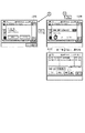
図20は、本発明の第2実施形態を示す画像処理装置における出力画像ジョブの管理テーブルの一例を示す図であり、画像入出力制御部3において、フォーマッタ部4やファクシミリ部5により入力し画像メモリ307のテンポラリ領域901に格納している画像を、プリンタ部2やファクシミリ部5に出力するという制御を行うために使用される出力画像管理テーブルに対応する。
【0148】
出力画像管理テーブル2000は、管理用のジョブ番号(JOB ID),画像出力先(Type of Job),ユーザID(User ID),ジョブ名(Name of Job),出力用紙サイズ(Paper Size),解像度(Resolution),プリントアウトもしくはファクシミリ送信時の出力パラメータ(Parameters of Print/Fax)、テンポラリ領域901の画像格納先アドレスを示すポインタ(* address1)、次の出力画像テーブルのアドレスを示すポインタ(* address2)から構成されている。
【0149】
出力画像管理テーブル2000は、フォーマッタ部4やファクシミリ部5よりジョブ開始要求命令を受け取り、ジョブ開始可能であると判定しジョブを受け付けた時点で作成され、受け付けた順に順次接続され出力画像キューを構成するものである。
【0150】
図21は、本発明に係る画像処理装置における第3のデータ処理手順の一例を示すフローチャートであり、画像入出力制御部3において、出力画像キューをチェックし、プリンタ部2もしくはファクシミリ部5に画像を出力するまでの処理に対応する。なお、(1)〜(9)は各ステップを示す。
【0151】
出力画像キューが存在する場合、画像出力先(出力画像キュー)をチェックし(1)、出力先がプリンタ部2への出力であったと判定した場合は、エラーが発生していないかプリンタ部2をチェックし(2)、プリンタ部2に特に異常はなく、出力可能であると判定すると、出力画像管理テーブル2000の画像格納先アドレス(テンポラリ領域901の画像格納先アドレスを示すポインタ(* address1))を参照し、テンポラリ領域901より画像を取り出してプリンタ部2に転送する(3)。
【0152】
次いで、格納されている全ての画像の出力が終了したかどうかを判定し(4)、全て画像の出力を終了していないと判定した場合は、ステップ(3)へ戻り、全て画像の出力を終了していると判定した場合には、格納していた画像を全て消去し、出力画像キューから出力画像管理テーブル2000を削除して(5)、ステップ(1)へ戻り、再び出力画像キューの取り出し処理へと移行する。
【0153】
一方、ステップ(1)において、画像出力先がファクシミリ部5であったと判定した場合は、出力画像管理テーブル2000の画像格納先アドレス(テンポラリ領域901の画像格納先アドレスを示すポインタ(* address1))を参照し、テンポラリ領域901より画像を取り出してファクシミリ部5に転送する(7)。
【0154】
次いで、プリンタ部2への出力時と同様に格納されている全ての画像の出力を終了したかどうかを判定し(8)、全て画像の出力を終了していないと判定した場合は、ステップ(7)へ戻り、全て画像の出力を終了していると判定した場合には、格納していた画像を全て消去し、出力画像キューから出力画像管理テーブル2000を削除して(9)、ステップ(1)へ戻り、再び出力画像キューの取り出し処理へと移行する。
【0155】
なお、ステップ(2)において、画像出力先がプリンタ部2であるが、プリンタ部2に障害が発生している場合(NGの場合)、出力画像キューの中から、画像出力先がファクシミリ部5である出力画像管理テーブルを検索し、該当する出力画像管理テーブルがみつからない場合は、ステップ(1)に戻り、該当する出力画像管理テーブル(図示しない)が見つかった場合、ステップ(7)へ移行し、ファクシミリ部5への画像出力処理を行う。
【0156】
図22は、本発明に係る画像処理装置における出力画像キューの一例を示す図であり、先頭の出力キューは、プリンタ部2への出力キューで、2番目にはファクシミリ部5への出力キューが格納されている場合に対応する。
【0157】
図22の(a)に示すような出力キューの状態の場合、プリンタ部2において障害が発生していると、上記図20に示した処理に従い、2番目のファクシミリ部5への出力キューが先に処理されることになり、図21のステップ(9)の実行に伴い、出力キューの状態は、図22の(b)に示すような出力キューの状態となる。
【0158】
以下、図23に示すメモリマップを参照して本発明に係る画像処理装置で読み出し可能なデータ処理プログラムの構成について説明する。
【0159】
図23は、本発明に係る画像処理装置で読み出し可能な各種データ処理プログラムを格納する記憶媒体のメモリマップを説明する図である。
【0160】
なお、特に図示しないが、記憶媒体に記憶されるプログラム群を管理する情報、例えばバージョン情報,作成者等も記憶され、かつ、プログラム読み出し側のOS等に依存する情報、例えばプログラムを識別表示するアイコン等も記憶される場合もある。
【0161】
さらに、各種プログラムに従属するデータも上記ディレクトリに管理されている。また、各種プログラムをコンピュータにインストールするためのプログラムや、インストールするプログラムが圧縮されている場合に、解凍するプログラム等も記憶される場合もある。
【0162】
本実施形態における図14,図15,図17,図21に示す機能が外部からインストールされるプログラムによって、情報処理装置7により遂行されていてもよい。そして、その場合、CD−ROMやフラッシュメモリやFD等の記憶媒体により、あるいはネットワークを介して外部の記憶媒体から、プログラムを含む情報群を出力装置に供給される場合でも本発明は適用されるものである。
【0163】
以上のように、前述した実施形態の機能を実現するソフトウエアのプログラムコードを記録した記憶媒体を、システムあるいは装置に供給し、そのシステムあるいは装置のコンピュータ(またはCPUやMPU)が記憶媒体に格納されたプログラムコードを読出し実行することによっても、本発明の目的が達成されることは言うまでもない。
【0164】
この場合、記憶媒体から読み出されたプログラムコード自体が本発明の新規な機能を実現することになり、そのプログラムコードを記憶した記憶媒体は本発明を構成することになる。
【0165】
プログラムコードを供給するための記憶媒体としては、例えば、フロッピーディスク,ハードディスク,光ディスク,光磁気ディスク,CD−ROM,CD−R,磁気テープ,不揮発性のメモリカード,ROM,EEPROM等を用いることができる。
【0166】
また、コンピュータが読み出したプログラムコードを実行することにより、前述した実施形態の機能が実現されるだけでなく、そのプログラムコードの指示に基づき、コンピュータ上で稼働しているOS(オペレーティングシステム)等が実際の処理の一部または全部を行い、その処理によって前述した実施形態の機能が実現される場合も含まれることは言うまでもない。
【0167】
さらに、記憶媒体から読み出されたプログラムコードが、コンピュータに挿入された機能拡張ボードやコンピュータに接続された機能拡張ユニットに備わるメモリに書き込まれた後、そのプログラムコードの指示に基づき、その機能拡張ボードや機能拡張ユニットに備わるCPU等が実際の処理の一部または全部を行い、その処理によって前述した実施形態の機能が実現される場合も含まれることは言うまでもない。
【0168】
上記各実施形態によれば、プリンタに障害が発生している場合に、展開動作を中断することなく継続し、展開画像を予めメモリ上に用意された仮想ボックスに出力するので、展開画像をプリントアウトする以外の例えばファクシミリ送信するような場合、これを先に処理することにより、ユーザの利便性を向上し、さらにトータル的な生産性をも向上する。
【0169】
【発明の効果】
以上説明したように、本発明によれば、画像出力手段に障害が発生しても、展開手段による展開処理を中断させることなく継続して画像情報を展開処理して、障害が解消するまで確実に記憶できるユーザ識別情報で管理可能な仮想メモリ領域で既に展開した画像情報を記憶管理することができる。
【0170】
また、出力可能となるまで展開した画像情報をいつでも出力可能に記憶しているので、前記画像出力手段に障害が発生しても、再度画像情報への再展開処理を不要として、意図する画像情報を高速に出力させることができる。
【0171】
さらに、仮想メモリ領域を障害が解消するまで確実に記憶できる記憶領域として利用させながら、既に展開した画像情報を特定のユーザでなければ出力できないように画像情報を記憶管理することができる。
【0172】
また、記憶媒体に起因する障害生じた場合に、画像展開手段による展開処理を中断させることなく継続して画像情報を展開処理して、障害が解消するまで確実に記憶できる記憶領域で既に展開した画像情報を記憶管理することができる。
【0173】
さらに、画像出力手段に障害が発生しても、画像展開手段による展開処理を中断させることなく継続して画像情報を展開処理して、障害が解消するまで確実に記憶できる第2の記憶手段で既に展開した画像情報を記憶管理できる。
【0174】
また、画像形成手段の障害が解消したら、ユーザからの出力指示がなくても、速やかに画像形成させることができ、ユーザによる操作指示負担を軽減し、ユーザの利便性を格段に向上できる。
【0175】
さらに、画像出力手段に障害が発生しても、画像展開手段による展開処理を中断させることなく継続して画像情報を展開処理して、障害が解消するまで確実に記憶できる記憶領域で既に展開した画像情報を記憶管理しながら、展開した画像情報を滞ることなく通信回線を介して外部機器に転送させることができ、入力される画像情報を展開して通信するような画像処理機能の効率を格段に向上させることができる。
【0176】
また、画像出力手段に障害が発生しても、画像展開手段による展開処理を中断させることなく継続して画像情報を展開処理して、障害が解消するまで確実に記憶できる仮想メモリ領域で既に展開した画像情報を記憶管理することができる。
【0177】
従って、画像情報を記録媒体に出力する処理中に画像出力が不可となるような事態が発生しても、画像情報展開処理を中断することなく継続させ、かつ、展開した画像情報を個別に管理して、随時あるいは自動的に出力させる画像処理環境を自在に整備でき、画像処理装置の各機能処理効率およびユーザの利便性を格段に向上させることができる等の効果を奏する。
【図面の簡単な説明】
【図1】本発明の第1実施形態を示す画像処理装置の構成を示すブロック図である。
【図2】図1に示したスキャナ部及びプリンタ部の構成例を示す断面図である。
【図3】図1に示したスキャナ部の詳細な構成例を示すブロック図である。
【図4】図1に示した画像入出力制御部の詳細な構成を示すブロック図である。
【図5】図1に示したフォーマッタ部の詳細な構成例を示すブロック図である。
【図6】図1に示したファクシミリ部の詳細な構成例を示すブロック図である。
【図7】図1に示したフォーマッタ部と画像入出力制御部とページ画像転送シーケンスの一例を示す図である。
【図8】図1に示したフォーマッタ部と画像入出力制御部との間におけるページ画像転送シーケンス中でやり取りされる制御コマンド及びデータの構成を示す図である。
【図9】図4に示した画像入出力制御部の画像メモリの論理的な使用領域を示した図である。
【図10】図1に示した操作部におけるパーソナルボックスの登録操作画面の一例を示す図である。
【図11】図9に示したパーソナルボックス領域のパーソナルボックスからの出力指示操作例の一例を示す図である。
【図12】図9に示したパーソナルボックス領域のパーソナルボックスからの出力指示操作例の一例を示す図である。
【図13】図4に示した画像入出力制御部のRAM上に保持されているボックス管理テーブルを示す図である。
【図14】本発明に係る画像処理装置における第1のデータ処理手順の一例を示すフローチャートである。
【図15】本発明に係る画像処理装置における第2のデータ処理手順の一例を示すフローチャートである。
【図16】図1に示したフォーマッタ部と画像入出力制御部とのページ画像転送シーケンスの一例を示す図である。
【図17】本発明に係る画像処理装置における第3のデータ処理手順の一例を示すフローチャートである。
【図18】図1に示したフォーマッタ部と画像入出力制御部とのページ画像転送シーケンスの一例を示す図である。
【図19】図1に示したフォーマッタ部と画像入出力制御部とのページ画像転送シーケンスの一例を示す図である。
【図20】本発明の第2実施形態を示す画像処理装置における出力画像ジョブの管理テーブルの一例を示す図である。
【図21】本発明に係る画像処理装置における第3のデータ処理手順の一例を示すフローチャートである。
【図22】本発明に係る画像処理装置における出力画像キューの一例を示す図である。
【図23】本発明に係る画像処理装置で読み出し可能な各種データ処理プログラムを格納する記憶媒体のメモリマップを説明する図である。
【符号の説明】
1 スキャナ部
2 プリンタ部
3 画像入出力制御部
4 フォーマッタ部
5 ファクシミリ部
6 操作部
300 インタフェース部
301 CPU
303 インタフェース部
304 ROM
305 RAM
306 画像処理部
307 画像メモリ[0001]
TECHNICAL FIELD OF THE INVENTION
The present invention relates to an image processing apparatus having various image input / output functions such as copy, print, and facsimile, a data processing method of the image processing apparatus, and a storage medium storing a computer-readable program.
[0002]
[Prior art]
2. Description of the Related Art Conventionally, an image processing apparatus that inputs data described in a page description language (hereinafter, also referred to as PDL data), forms an image, and outputs the image, including a scanner and communication means, such as a copy function, a print function, and a facsimile function. There has been proposed an apparatus that realizes a plurality of image output functions using one image forming unit.
[0003]
In addition, not only is it possible to print out the image data that has been developed to be printable from the printer as it is, but also to perform various complex function processing such as facsimile transmission, transfer to an image storage device, and user's arbitrary printing later. ing.
[0004]
[Problems to be solved by the invention]
However, in such a configuration, for example, when a paper jam or the like occurs during copying and the printer cannot be used, the function of expanding the PDL data also cannot print out the expanded image. Until it became available, it had to stop the deployment operation or go offline to stop accepting data from the host.
[0005]
As described above, while a plurality of image output functions can be realized by one apparatus, if a failure occurs in a printer in a certain function, the functions using other printers are not removed unless the failure of the printer is removed. Function processing could not be continued.
[0006]
Above all, especially in the copy function and the facsimile function, since the user operates in front of the apparatus, if a failure occurs in the printer, it is possible to expect the operation of removing the failure on the spot and continuing the copy or facsimile function. However, since the PDL print function mainly executes a function remotely, such as an information processing device connected on a network, a fault occurring in the printer is removed to the device at the place, and the information processing is performed again. The operation of giving a print instruction from the apparatus is extremely complicated, and there is a problem that the operability of the entire system is low.
[0007]
The present invention has been made in order to solve the above-described problems, and an object of the present invention is to provide an image processing apparatus that can perform image output even when a situation where image output becomes impossible during a process of outputting image information to a recording medium occurs. By continuing the information expansion processing without interruption and managing the expanded image information individually, an image processing environment for outputting at any time or automatically can be freely prepared, and the processing efficiency of each function of the image processing apparatus and It is an object of the present invention to provide an image processing apparatus, a data processing method of the image processing apparatus, and a storage medium storing a computer-readable program which can significantly improve the convenience of the user.
[0008]
[Means for Solving the Problems]
According to a first aspect of the present invention, there is provided image reading means for reading an image, data input means for inputting image information described in a predetermined page description language, and image information input from the data input means as visible information. A temporary area for storing the image information read by the image reading means and the image information expanded by the image reading means, and a virtual memory area manageable by user identification information. An image storage unit capable of securing a storage area of the image storage unit, an image output unit that outputs image information stored in the image storage unit, and an output state of the image output unit. Storage destination of the image information read by the image reading unit or the image information expanded by the image expansion unit in the plurality of storage areas And having a changing means for changing.
[0009]
According to a second aspect of the present invention, there is provided image reading means for reading an image, data input means for inputting image information described in a predetermined page description language, and image information input from the data input means as visible information. A temporary area for storing the image information read by the image reading means and the image information expanded by the image reading means, and a virtual memory area manageable by user identification information. A data processing method for an image processing apparatus, comprising: an image storage unit capable of securing a storage area of the image storage unit; and an image output unit that outputs image information stored in the image storage unit. The image information read by the image reading means for the plurality of storage areas or developed by the image developing means. It characterized by having a change step of changing a storage destination for the plurality of storage areas of the image information.
[0010]
In a third aspect according to the present invention, the image output means includes an image forming means for outputting image information on a recording medium.
[0011]
In a fourth aspect according to the present invention, the image output means includes communication means for outputting image information to a predetermined communication line.
[0012]
In a fifth aspect according to the present invention, the image output means includes an image forming means for outputting image information on a recording medium and a communication means for outputting image information on a predetermined communication line.
[0013]
According to a sixth aspect of the present invention, there is provided an image reading means for reading an image, a data input means for inputting image information described in a predetermined page description language, and a method for converting the image information input from the data input means into a visible image. A first image storage unit for temporarily storing the image information read by the image reading unit and the image information expanded by the image reading unit; and an image reading unit reading the image information read by the image reading unit. A second image storage unit that stores the image information expanded by the image expansion unit and the image information expanded by the image expansion unit in a manner that can be managed by user identification information, and is stored in the first image storage unit or the second image storage unit. Image forming means for outputting the image information on the recording medium, and determining the output state of the image forming means and reading the image information by the image reading means. In which a control means for changing the storage destination of the image information expanded by the image information or the image developing means from the first image storing unit to the second image storage means.
[0014]
In a seventh aspect according to the present invention, the control unit determines an output state of the image forming unit, automatically reads out image information stored in the second storage unit, and sends the image information to the image forming unit. Output.
[0016]
The
[0017]
The
The
[0018]
BEST MODE FOR CARRYING OUT THE INVENTION
[First Embodiment]
FIG. 1 is a block diagram illustrating a configuration of an image processing apparatus according to the first embodiment of the present invention.
[0019]
In FIG. 1,
[0020]
The
[0021]
The
[0022]
The
[0023]
In accordance with an instruction from the image input /
[0024]
FIG. 2 is a cross-sectional view illustrating a configuration example of the
[0025]
In the
[0026]
When the document is conveyed onto the
[0027]
In the
[0028]
The recording paper is conveyed to the transfer unit 206 by either the
[0029]
Then, the recording paper to which the developer has been transferred is conveyed to the fixing
[0030]
When the sorter mode is not set to the sorting mode, the
[0031]
Further, when the multiplex recording mode is set, the recording paper is guided to the
[0032]
FIG. 3 is a block diagram showing a detailed configuration example of the
[0033]
In the figure, a
[0034]
The image data output from the
[0035]
In addition, the
[0036]
For example, when a mode in which copying is performed after the trimming process is instructed, the
[0037]
For example, when the facsimile transmission mode is instructed, the read image data is transferred to the image input /
[0038]
FIG. 4 is a block diagram showing a detailed configuration of the image input /
[0039]
In the figure,
[0040]
Image data input from the
[0041]
Image data input from the
[0042]
These image data stored in the
[0043]
When receiving a command requesting display on the
[0044]
Further, when an operation is performed by the user on the
[0045]
A control program of the
[0046]
FIG. 5 is a block diagram showing a detailed configuration example of the
[0047]
In the figure, a
[0048]
The PDL data sent from the information processing device (host computer) 7 is stored in the
[0049]
The
[0050]
Display screens and setting information relating to the operation of the
[0051]
The
[0052]
For example, when the clear operation of the reception buffer of the
[0053]
A control program of the
[0054]
Hereinafter, the characteristic configuration of the present embodiment will be described with reference to FIG.
[0055]
In the image processing apparatus configured as described above, an image reading unit (scanner unit 1) for reading an image, a data input unit (host interface unit 400) for inputting image information described in a predetermined page description language, An image expanding unit (formatter unit 4) for expanding the image information input from the data input unit into a visible image, and storing the image information read by the image reading unit and the image information expanded by the image expanding unit. Image storage means (image memory 307) capable of securing a plurality of storage areas (
[0056]
Furthermore, since the plurality of storage areas include a virtual memory area (personal box area 902) that can be managed by user identification information, the virtual memory area can be used as a storage area that can be securely stored until the failure is resolved. Image information that has already been developed can be stored and managed so that it can be output only by a specific user.
[0057]
Further, the image output means includes an image forming means (printer section 2) for outputting image information on a recording medium, or includes a communication means (facsimile section 5) for outputting image information to a predetermined communication line. Or a
[0058]
Further, a
[0059]
Further, the
[0060]
Further, an image reading unit (scanner unit 1) for reading an image, a data input unit (host interface unit 400) for inputting image information described in a predetermined page description language, and an image information input from the data input unit Developing means (formatter unit 4) for developing the image into a visible image, and a plurality of storage areas for storing the image information read by the image reading means and the image information developed by the image developing means (see FIG. 9 described later). An image storage means (image memory 307) capable of securing a
[0061]
FIG. 6 is a block diagram showing a detailed configuration example of the
[0062]
In the figure,
[0063]
At the time of facsimile reception, reception data received from the telephone line is demodulated by the
[0064]
The
[0065]
On the other hand, at the time of facsimile transmission, the image data transferred from the image input /
[0066]
Then, the
[0067]
Display screens and setting information relating to the operation of the
[0068]
Further, the
[0069]
A control program of the
[0070]
As described above, the image input /
[0071]
FIG. 7 is a diagram showing an example of the
[0072]
The
[0073]
If the image input /
[0074]
Upon receiving “OK” from the image input /
[0075]
If the image input /
[0076]
When the
[0077]
The image input /
[0078]
Thereafter, each time a page image for one page is generated in the
[0079]
The
[0080]
FIG. 8 is a diagram showing a configuration of control commands and data exchanged in the page image transfer sequence between the
[0081]
FIG. 8A shows a control command indicating a job start request, and “START” indicates a job start request. “Type of Job” indicates the type of job. The job types include a print job for outputting an image input from the
[0082]
“User ID” indicates the ID of a user who has executed a job on the
[0083]
“Paper Size” indicates the output paper size. “Resolution” indicates the resolution of the bitmap image created in the
[0084]
FIG. 8B shows parameters at the time of a print output job, and “Page Orientation” shows the orientation (Portlage / Landscape) of the drawn image.
[0085]
“Duplex mode” indicates single-sided output / double-sided output. “Bind direction” indicates a binding direction (Longage Feed / Shortage Feed). “Sorting mode” indicates a sorting method (not sorting / sorting / group sorting).
[0086]
“Finishing mode” indicates a finishing mode (staple / punch). “Darkness” indicates the toner density (1 to 9). “Personal box No.” indicates the number (1 to 99) of the virtual memory box provided on the
[0087]
FIG. 8C shows parameters at the time of facsimile transmission job, and “Resolution of fax” shows the resolution at the time of facsimile transmission. "Fax
No. (N) "indicates a destination telephone number. "Subaddress" is Fax
No. Indicates a subaddress attached to.
[0088]
FIG. 8D shows a control command indicating page image output, and “PAGE” indicates page image output. “Page No.” indicates a page number. “Number of copies” indicates the number of times the same page image is repeatedly output when an image is output from the
[0089]
FIG. 8E shows a control command indicating the end of the job, and “END” indicates the end of the job. “Completion Status” indicates whether the job has been completed normally or abnormally in the
[0090]
FIG. 8F shows status response data indicating a result of accepting a request in the image input /
[0091]
Next, the image developed by the
[0092]
The personal box function is, for example, when printing out a confidential document that one does not want others to see, temporarily storing the document in a memory such as an
[0093]
This function is used when the same document is to be printed out many times by changing the output form.
[0094]
FIG. 9 is a diagram showing a logical use area of the
[0095]
In the figure, a
[0096]
The
[0097]
Next, a usage example of the personal box function will be described.
[0098]
[Personal box registration process]
Hereinafter, the registration process of the personal box will be described with reference to FIG.
[0099]
FIG. 10 is a diagram illustrating an example of a personal box registration operation screen on the
[0100]
In the figure,
[0101]
First, on the
[0102]
On the
[0103]
When the box name is input in this way and the OK button is selected on the
[0104]
After setting the password in this manner or without setting it, by selecting the OK button on the
[0105]
[Output processing from personal box]
Hereinafter, the output process from the personal box will be described with reference to FIGS.
[0106]
FIGS. 11 and 12 are diagrams showing an example of an output instruction operation from the personal box in the
[0107]
In these figures,
[0108]
First, on a
[0109]
At this time, if a password is set in the selected box, a
[0110]
Therefore, when a password is set, the password is input on the
[0111]
On the other hand, if the password is correct, the screen moves to the
[0112]
Here, a list of documents stored in the selected box is displayed on the
[0113]
The document name is added by the application that created the document or a printer driver when the image data is output from the
[0114]
The user selects a document to be printed out from the document list stored on the
[0115]
After a document to be printed out is selected in this way, when a print button is designated on the
[0116]
The
[0117]
When the printout is completed in this manner, a
[0118]
FIG. 13 is a diagram showing a box management table held on the
[0119]
In the figure, a box management table 1201 is prepared for each box number, and includes a box number (PB No.), a box name (PB Name), a password (Pass Code), a user ID (User ID), and a box procedure. (PB Size) and a pointer (pointer) indicating the address of the document management table (document management table 1202) stored in the box. * address).
[0120]
[0121]
[0122]
The operation contents shown in FIGS. 10, 11, and 12 are input from the
[0123]
Next, a process in which the image input /
[0124]
FIG. 14 is a flowchart illustrating an example of a first data processing procedure in the image processing apparatus according to the present invention. Note that (1) to (5) indicate each step.
[0125]
First, it waits for the job start request command (START-REQ) to be notified from the formatter unit 4 (1). When the job start request command is notified, the type of job (Type of Job) is determined from the notified command. ) Is determined (2). Hereinafter, when it is determined that the job is a personal box job according to the type of job, a personal box job routine is executed (3), and when it is determined that the job is a print job, a print job routine is executed (4) and facsimile is performed. If it is determined that the job is a job, a facsimile job routine is executed (5), and after the execution of each routine is completed, the routine returns.
[0126]
FIG. 15 is a flowchart illustrating an example of a second data processing procedure in the image processing apparatus according to the present invention. Note that (1) to (5) indicate each step. FIG. 16 is a diagram showing an example of a page image transfer sequence between the
[0127]
First, if the job is a personal box job, the box number is extracted (1), the box management table 1201 shown in FIG. 13 is searched (2), and the designated box number is a registered box. (3), and if it is determined that the corresponding box exists and can be stored in the box, “OK” is returned to the formatter unit 4 (4), and the process is performed. finish.
[0128]
On the other hand, if it is determined in step (3) that the specified box is not registered or that the storage area of the specified box is full and cannot be stored, “NG” is returned to the formatter unit 4 (5). ), End the process. If “NG” is returned, the
[0129]
FIG. 17 is a flowchart illustrating an example of a third data processing procedure in the image processing apparatus according to the present invention. (1) to (8) indicate each step. 18 and 19 are diagrams illustrating an example of a page image transfer sequence between the
[0130]
If it is determined in step (2) shown in FIG. 14 that the job is a print job, it is checked whether an area for storing the image from the
[0131]
On the other hand, if it is determined in step (1) that the
[0132]
This is for confirming that the image output from the
[0133]
If it is determined in step (2) that an abnormality has occurred in the
[0134]
Next, it is determined whether or not the corresponding personal box is found (5). If the corresponding personal box is found and it is determined that the personal box can be stored in the personal box area, the storage destination of the image from the
[0135]
On the other hand, in step (2), it is determined that no abnormality has occurred in the
[0136]
In this case, as shown in FIG. 19, in response to the job start request (START-REQ) from the
[0137]
In step (6), the job whose storage destination has been changed from the
[0138]
Further, the fact that the image data is not output to the
[0139]
Therefore, the user later goes to the main body, and if the main body still has a fault, after removing the fault on the spot, the output screen shown in FIG. By opening the
[0140]
Further, in the present embodiment, it is also possible to adopt a configuration in which the data is automatically output to the
[0141]
Then, the image input /
[0142]
Thereby, the document saved in the personal box is automatically printed out.
[0143]
As described above, when the image input /
[0144]
Hereinafter, the characteristic configuration of the present embodiment will be further described with reference to FIG.
[0145]
An image reading unit (scanner unit 1) configured to read an image configured as described above, a data input unit (host interface unit 400) for inputting image information described in a predetermined page description language, and a data input unit An image expanding unit (formatter unit 4) for expanding the input image information into a visible image, and a plurality of storage areas for storing the image information read by the image reading unit and the image information expanded by the image expanding unit. A data processing method of an image processing apparatus having image storage means (image memory 307) capable of being secured and image output means (printer unit 2) for outputting image information stored in the image storage means; or Image reading means for reading an image, data input means for inputting image information described in a predetermined page description language, Image expansion means for expanding the image information input from the data input means into a visible image, and a plurality of storage areas for storing the image information read by the image reading means and the image information expanded by the image development means. A storage medium storing a computer-readable program for controlling an image processing apparatus having a securable image storage means and an image output means for outputting image information stored in the image storage means, A determining step (steps (1) and (2) in FIG. 17) for determining the storage state of the image data in one of the storage areas in the image storage unit and the output state of the image output unit; The storage state of the image data in the storage area is in the storage disabled state, or the storage state of the image data in the storage area is in the storage disabled state. When it is determined that the image output from the
[0146]
[Second embodiment]
In the first embodiment, the control of the input image job from the
[0147]
FIG. 20 is a diagram showing an example of an output image job management table in the image processing apparatus according to the second embodiment of the present invention. In the image input /
[0148]
The output image management table 2000 includes a management job number (JOB ID), an image output destination (Type of Job), a user ID (User ID), a job name (Name of Job), an output paper size (Paper Size), and a resolution. (Resolution), output parameters (Parameters of Print / Fax) at the time of printout or facsimile transmission, and a pointer (Pointer) indicating an image storage destination address of the
[0149]
The output image management table 2000 is created when a job start request command is received from the
[0150]
FIG. 21 is a flowchart showing an example of a third data processing procedure in the image processing apparatus according to the present invention. The image input /
[0151]
If an output image queue exists, the image output destination (output image queue) is checked (1). If it is determined that the output destination is output to the
[0152]
Next, it is determined whether the output of all the stored images has been completed (4). If it is determined that the output of all the images has not been completed, the process returns to step (3), and the output of all the images is performed. If it is determined that the processing has been completed, all stored images are deleted, the output image management table 2000 is deleted from the output image queue (5), and the process returns to step (1), where the output image queue is deleted again. Move on to the extraction process.
[0153]
On the other hand, if it is determined in step (1) that the image output destination is the
[0154]
Next, it is determined whether the output of all the stored images has been completed as in the case of the output to the printer unit 2 (8). If it is determined that the output of all the images has not been completed, the process proceeds to step ( Returning to 7), if it is determined that the output of all images has been completed, all stored images are deleted, the output image management table 2000 is deleted from the output image queue (9), and step (9) is performed. Returning to 1), the process shifts to the output image queue extracting process again.
[0155]
In step (2), if the image output destination is the
[0156]
FIG. 22 is a diagram illustrating an example of an output image queue in the image processing apparatus according to the present invention. The first output queue is an output queue to the
[0157]
In the case of the output queue as shown in FIG. 22A, if a failure has occurred in the
[0158]
Hereinafter, the configuration of a data processing program readable by the image processing apparatus according to the present invention will be described with reference to a memory map shown in FIG.
[0159]
FIG. 23 is a diagram illustrating a memory map of a storage medium that stores various data processing programs that can be read by the image processing apparatus according to the present invention.
[0160]
Although not shown, information for managing a group of programs stored in the storage medium, for example, version information, a creator, and the like are also stored, and information dependent on the OS or the like on the program reading side, for example, a program is identified and displayed. Icons and the like may also be stored.
[0161]
Further, data dependent on various programs is also managed in the directory. In addition, a program for installing various programs on a computer or a program for decompressing a program to be installed when the program to be installed is compressed may be stored.
[0162]
The functions shown in FIG. 14, FIG. 15, FIG. 17, and FIG. 21 in the present embodiment may be executed by the
[0163]
As described above, the storage medium storing the program codes of the software for realizing the functions of the above-described embodiments is supplied to the system or the apparatus, and the computer (or CPU or MPU) of the system or the apparatus stores the storage medium in the storage medium. It goes without saying that the object of the present invention is also achieved by reading and executing the program code thus obtained.
[0164]
In this case, the program code itself read from the storage medium implements the novel function of the present invention, and the storage medium storing the program code constitutes the present invention.
[0165]
As a storage medium for supplying the program code, for example, a floppy disk, hard disk, optical disk, magneto-optical disk, CD-ROM, CD-R, magnetic tape, nonvolatile memory card, ROM, EEPROM, or the like can be used. it can.
[0166]
When the computer executes the readout program code, not only the functions of the above-described embodiments are realized, but also an OS (Operating System) running on the computer based on the instruction of the program code. It goes without saying that a part or all of the actual processing is performed and the functions of the above-described embodiments are realized by the processing.
[0167]
Further, after the program code read from the storage medium is written into a memory provided on a function expansion board inserted into the computer or a function expansion unit connected to the computer, the function expansion is performed based on the instruction of the program code. It goes without saying that a CPU or the like provided in the board or the function expansion unit performs part or all of the actual processing, and the processing realizes the functions of the above-described embodiments.
[0168]
According to each of the above embodiments, when a failure occurs in the printer, the expansion operation is continued without interruption, and the expansion image is output to the virtual box prepared in advance in the memory, so that the expansion image is printed. For example, in the case of facsimile transmission other than out-of-out, by processing this first, user convenience is improved and total productivity is also improved.
[0169]
【The invention's effect】
As described above, according to the present invention, even if a failure occurs in the image output unit, the image information is continuously expanded without interrupting the expansion processing by the expansion unit, and it is ensured until the failure is resolved. Image information that has already been developed can be stored and managed in a virtual memory area that can be managed by user identification information that can be stored in a storage area.
[0170]
Further, since the image information expanded until it can be output is stored so as to be able to be output at any time, even if a failure occurs in the image output means, it is not necessary to re-develop the image information again, and the intended image information can be output. Can be output at high speed.
[0171]
Furthermore, while using the virtual memory area as a storage area that can be reliably stored until the failure is resolved, image information that has already been developed can be stored and managed so that only a specific user can output the already expanded image information.
[0172]
Further, when a failure due to the storage medium occurs, the image information is continuously expanded without interrupting the expansion processing by the image expansion unit, and the image information is already expanded in a storage area that can be securely stored until the failure is resolved. Image information can be stored and managed.
[0173]
Further, even if a failure occurs in the image output means, the second storage means can continuously develop the image information without interrupting the development processing by the image development means and store the image information reliably until the failure is resolved. Image information that has already been developed can be stored and managed.
[0174]
Further, when the failure of the image forming means is eliminated, the image can be formed promptly without the output instruction from the user, the burden of the operation instruction by the user can be reduced, and the convenience of the user can be remarkably improved.
[0175]
Further, even if a failure occurs in the image output unit, the image information is continuously expanded without interrupting the expansion processing by the image expansion unit, and the image information is already expanded in a storage area that can be reliably stored until the failure is resolved. While storing and managing the image information, the developed image information can be transferred to an external device via a communication line without delay, and the efficiency of the image processing function of expanding and communicating the input image information is remarkably improved. Can be improved.
[0176]
Further, even if a failure occurs in the image output unit, the image information is continuously expanded without interrupting the expansion processing by the image expansion unit, and the image information is already expanded in the virtual memory area where the failure can be reliably stored until the failure is resolved. The stored image information can be stored and managed.
[0177]
Therefore, even if the image output becomes impossible during the process of outputting the image information to the recording medium, the image information expanding process is continued without interruption, and the expanded image information is individually managed. As a result, an image processing environment for outputting images as needed or automatically can be freely prepared, and the effects such as the efficiency of processing each function of the image processing apparatus and the convenience of the user can be significantly improved.
[Brief description of the drawings]
FIG. 1 is a block diagram illustrating a configuration of an image processing apparatus according to a first embodiment of the present invention.
FIG. 2 is a cross-sectional view illustrating a configuration example of a scanner unit and a printer unit illustrated in FIG.
FIG. 3 is a block diagram illustrating a detailed configuration example of a scanner unit illustrated in FIG. 1;
FIG. 4 is a block diagram illustrating a detailed configuration of an image input / output control unit illustrated in FIG. 1;
FIG. 5 is a block diagram illustrating a detailed configuration example of a formatter unit illustrated in FIG. 1;
FIG. 6 is a block diagram illustrating a detailed configuration example of a facsimile unit illustrated in FIG. 1;
FIG. 7 is a diagram illustrating an example of a formatter unit, an image input / output control unit, and a page image transfer sequence illustrated in FIG. 1;
8 is a diagram showing a configuration of control commands and data exchanged in a page image transfer sequence between the formatter unit and the image input / output control unit shown in FIG.
9 is a diagram illustrating a logical use area of an image memory of the image input / output control unit illustrated in FIG. 4;
FIG. 10 is a diagram showing an example of a personal box registration operation screen in the operation unit shown in FIG. 1;
FIG. 11 is a diagram showing an example of an output instruction operation from a personal box in the personal box area shown in FIG. 9;
FIG. 12 is a diagram illustrating an example of an output instruction operation example from the personal box in the personal box area illustrated in FIG. 9;
FIG. 13 is a diagram illustrating a box management table held on a RAM of the image input / output control unit illustrated in FIG. 4;
FIG. 14 is a flowchart illustrating an example of a first data processing procedure in the image processing apparatus according to the present invention.
FIG. 15 is a flowchart illustrating an example of a second data processing procedure in the image processing apparatus according to the present invention.
FIG. 16 is a diagram illustrating an example of a page image transfer sequence between the formatter unit and the image input / output control unit illustrated in FIG.
FIG. 17 is a flowchart illustrating an example of a third data processing procedure in the image processing apparatus according to the present invention.
FIG. 18 is a diagram showing an example of a page image transfer sequence between the formatter unit and the image input / output control unit shown in FIG.
19 is a diagram illustrating an example of a page image transfer sequence between the formatter unit and the image input / output control unit illustrated in FIG.
FIG. 20 is a diagram illustrating an example of an output image job management table in the image processing apparatus according to the second embodiment of the present invention.
FIG. 21 is a flowchart illustrating an example of a third data processing procedure in the image processing apparatus according to the present invention.
FIG. 22 is a diagram illustrating an example of an output image queue in the image processing apparatus according to the present invention.
FIG. 23 is a diagram illustrating a memory map of a storage medium that stores various data processing programs that can be read by the image processing apparatus according to the present invention.
[Explanation of symbols]
1 Scanner section
2 Printer section
3 Image input / output control unit
4 Formatter part
5 Facsimile part
6 Operation section
300 Interface section
301 CPU
303 Interface section
304 ROM
305 RAM
306 Image processing unit
307 Image memory
Claims (10)
所定のページ記述言語で記述された画像情報を入力するデータ入力手段と、
前記データ入力手段より入力された画像情報を可視情報に展開する画像展開手段と、
前記画像読取り手段により読み取られた画像情報および前記画像展開手段により展開された画像情報を記憶するためのテンポラリ領域とユーザ識別情報で管理可能な仮想メモリ領域を含む複数の記憶領域が確保可能な画像記憶手段と、
前記画像記憶手段に記憶されている画像情報を出力する画像出力手段と、
前記画像出力手段の出力状態を判定して、前記複数の記憶領域に対する前記画像読取り手段により読み取られた画像情報または前記画像展開手段により展開された画像情報の前記複数の記憶領域に対する記憶先を変更する変更手段と、
を有することを特徴とする画像処理装置。Image reading means for reading an image,
Data input means for inputting image information described in a predetermined page description language;
Image developing means for expanding the image information input from the data input means into visible information,
An image in which a plurality of storage areas including a temporary area for storing image information read by the image reading unit and image information expanded by the image expansion unit and a virtual memory area manageable by user identification information can be secured. Storage means;
Image output means for outputting image information stored in the image storage means,
The output state of the image output means is determined, and the storage destination of the image information read by the image reading means in the plurality of storage areas or the image information expanded by the image expansion means in the plurality of storage areas is changed. Means to change;
An image processing apparatus comprising:
前記画像出力手段の出力状態を判定して、前記複数の記憶領域に対する前記画像読取り手段により読み取られた画像情報または前記画像展開手段により展開された画像情報の前記複数の記憶領域に対する記憶先を変更する変更工程と、
を有することを特徴とする画像処理装置のデータ処理方法。Image reading means for reading an image, data input means for inputting image information described in a predetermined page description language, image developing means for expanding the image information input from the data input means into visible information, and the image Image storage means capable of securing a plurality of storage areas including a temporary area for storing image information read by reading means and image information expanded by the image expansion means and a virtual memory area manageable by user identification information And a data processing method of an image processing apparatus, comprising: an image output unit that outputs image information stored in the image storage unit.
The output state of the image output means is determined, and the storage destination of the image information read by the image reading means in the plurality of storage areas or the image information expanded by the image expansion means in the plurality of storage areas is changed. Change process,
A data processing method for an image processing apparatus, comprising:
所定のページ記述言語で記述された画像情報を入力するデータ入力手段と、
前記データ入力手段より入力された画像情報を可視画像に展開する画像展開手段と、
前記画像読取り手段により読み取られた画像情報および前記画像展開手段により展開された画像情報を一時的に記憶する第1の画像記憶手段と、
前記画像読取り手段により読み取られた画像情報および前記画像展開手段により展開された画像情報を、ユーザ識別情報で管理可能に記憶する第2の画像記憶手段と、
前記第1の画像記憶手段または前記第2の画像記憶手段に記憶されている画像情報を記録媒体上に出力する画像形成手段と、
前記画像形成手段の出力状態を判定して、前記画像読取り手段により読み取られた画像情報または前記画像展開手段により展開された画像情報の記憶先を前記第1の画像記憶手段から前記第2の画像記憶手段に変更する制御手段と、
を有することを特徴とする画像処理装置。Image reading means for reading an image,
Data input means for inputting image information described in a predetermined page description language;
Image developing means for developing the image information input from the data input means into a visible image,
First image storage means for temporarily storing image information read by the image reading means and image information expanded by the image expansion means;
A second image storage unit that stores the image information read by the image reading unit and the image information expanded by the image expansion unit in a manageable manner by user identification information;
Image forming means for outputting image information stored in the first image storage means or the second image storage means to a recording medium;
The output state of the image forming unit is determined, and the storage destination of the image information read by the image reading unit or the image information expanded by the image expanding unit is stored in the second image from the first image storage unit. Control means for changing to storage means;
An image processing apparatus comprising:
前記画像記憶手段中のテンポラリ領域に対する画像データの記憶状態と前記画像出力手段の出力状態とを判定する判定工程と、
前記判定工程により、前記テンポラリ領域に対する画像データの記憶状態が記憶不可状態で、かつ、前記画像出力手段からの画像出力が不可状態であると判定した場合に、前記画像読取り手段により読み取られた画像情報または前記画像展開手段により展開された画像情報の前記複数の記憶領域に対する記憶先を前記仮想メモリ領域に変更する変更工程と、
を有することを特徴とする画像処理装置のデータ処理方法。Image reading means for reading an image, data input means for inputting image information described in a predetermined page description language, image developing means for expanding the image information input from the data input means into a visible image, and the image Image storage means capable of securing a plurality of storage areas including a temporary area for storing image information read by reading means and image information expanded by the image expansion means and a virtual memory area manageable by user identification information And a data processing method of an image processing apparatus having image output means for outputting image information stored in the image storage means,
A determining step of determining a storage state of image data for a temporary area in the image storage unit and an output state of the image output unit;
The image read by the image reading means when the storage state of the image data with respect to the temporary area is determined to be in the storage disabled state and the image output from the image output means is determined to be in the disabled state by the determination step. A change step of changing a storage destination of the information or the image information expanded by the image expansion unit to the plurality of storage areas to the virtual memory area;
A data processing method for an image processing apparatus, comprising:
前記画像記憶手段中の前記テンポラリ領域に対する画像データの記憶状態と前記画像出力手段の出力状態とを判定する判定工程と、
前記判定工程により、前記テンポラリ領域に対する画像データの記憶状態が記憶不可状態で、かつ、前記画像出力手段からの画像出力が不可状態であると判定した場合に、前記画像読取り手段により読み取られた画像情報または前記画像展開手段により展開された画像情報の前記複数の記憶領域に対する記憶先を前記仮想メモリ領域に変更する変更工程とを有することを特徴とするコンピュータが読み出し可能なプログラムを格納した記憶媒体。Image reading means for reading an image, data input means for inputting image information described in a predetermined page description language, image developing means for expanding the image information input from the data input means into a visible image, and the image Image storage means capable of securing a plurality of storage areas including a temporary area for storing image information read by reading means and image information expanded by the image expansion means and a virtual memory area manageable by user identification information And a storage medium storing a computer-readable program for controlling an image processing apparatus having image output means for outputting image information stored in the image storage means,
A determining step of determining a storage state of image data for the temporary area in the image storage unit and an output state of the image output unit;
The image read by the image reading means when the storage state of the image data with respect to the temporary area is determined to be in the storage disabled state and the image output from the image output means is determined to be in the disabled state by the determination step. Changing a storage destination of the information or the image information expanded by the image expansion unit in the plurality of storage areas to the virtual memory area, wherein the storage medium stores a computer-readable program. .
前記画像形成手段の出力状態を判定して、前記画像読取り手段により読み取られた画像情報または前記画像展開手段により展開された画像情報の記憶先を前記第1の画像記憶手段から前記第2の画像記憶手段に変更する制御工程と、
を有することを特徴とするデータ処理方法。Image reading means for reading an image, data input means for inputting image information described in a predetermined page description language, image developing means for expanding the image information input from the data input means into a visible image, and the image First image storage means for temporarily storing the image information read by the reading means and the image information developed by the image developing means, and the image information read by the image reading means and developed by the image developing means Second image storage means for storing the obtained image information in a manageable manner by user identification information, and storing the image information stored in the first image storage means or the second image storage means on a recording medium. A data processing method of an image processing apparatus having an image forming unit for outputting,
The output state of the image forming unit is determined, and the storage destination of the image information read by the image reading unit or the image information expanded by the image expanding unit is stored in the second image from the first image storage unit. A control step of changing to storage means;
A data processing method comprising:
Priority Applications (1)
| Application Number | Priority Date | Filing Date | Title |
|---|---|---|---|
| JP30199797A JP3604885B2 (en) | 1997-11-04 | 1997-11-04 | Image processing apparatus, data processing method for image processing apparatus, and storage medium storing computer-readable program |
Applications Claiming Priority (1)
| Application Number | Priority Date | Filing Date | Title |
|---|---|---|---|
| JP30199797A JP3604885B2 (en) | 1997-11-04 | 1997-11-04 | Image processing apparatus, data processing method for image processing apparatus, and storage medium storing computer-readable program |
Publications (2)
| Publication Number | Publication Date |
|---|---|
| JPH11146114A JPH11146114A (en) | 1999-05-28 |
| JP3604885B2 true JP3604885B2 (en) | 2004-12-22 |
Family
ID=17903649
Family Applications (1)
| Application Number | Title | Priority Date | Filing Date |
|---|---|---|---|
| JP30199797A Expired - Fee Related JP3604885B2 (en) | 1997-11-04 | 1997-11-04 | Image processing apparatus, data processing method for image processing apparatus, and storage medium storing computer-readable program |
Country Status (1)
| Country | Link |
|---|---|
| JP (1) | JP3604885B2 (en) |
Families Citing this family (1)
| Publication number | Priority date | Publication date | Assignee | Title |
|---|---|---|---|---|
| JP6379053B2 (en) * | 2015-01-29 | 2018-08-22 | 株式会社沖データ | Image processing device |
-
1997
- 1997-11-04 JP JP30199797A patent/JP3604885B2/en not_active Expired - Fee Related
Also Published As
| Publication number | Publication date |
|---|---|
| JPH11146114A (en) | 1999-05-28 |
Similar Documents
| Publication | Publication Date | Title |
|---|---|---|
| JP4035232B2 (en) | Image forming apparatus and control method thereof | |
| US7161691B2 (en) | Method and apparatus for multiple media printing | |
| US8059286B2 (en) | System and program product | |
| JP4612781B2 (en) | Printing apparatus and printing apparatus control method and program | |
| US7161711B2 (en) | Information processing apparatus and method for creating print data and storage medium | |
| US8085429B2 (en) | Information processing apparatus and method for generating print data for a book with a cover sheet | |
| US8305603B2 (en) | Job processing apparatus coordinating update of software used in job execution and control method thereof | |
| US8184309B2 (en) | Printing system and job processing method with inhibition and designation of function and deletion of associated jobs | |
| US20060028678A1 (en) | Image processing apparatus and its control method | |
| US7362465B2 (en) | Information processing apparatus and control method therefor | |
| US6661527B1 (en) | Image input/output apparatus, image input/output method and image processing system | |
| JP3703375B2 (en) | Image processing apparatus and image processing method | |
| US6307615B1 (en) | Image processing apparatus, image processing method and image processing system | |
| JP4673037B2 (en) | Image display apparatus, image display apparatus control method, and program | |
| JP3604885B2 (en) | Image processing apparatus, data processing method for image processing apparatus, and storage medium storing computer-readable program | |
| JPH1145031A (en) | Image forming device | |
| JP2000330752A (en) | Device, system and method for forming image and storage medium | |
| JP2006166214A (en) | Image forming apparatus | |
| JP2000259377A (en) | Storage medium storing data processor, image output controller, data transfer method, image output control method and computer readable program | |
| JP3745134B2 (en) | Image input / output system and image input / output method | |
| JP2006205442A (en) | Image forming apparatus, information processing method, program, and memory medium | |
| JP4393536B2 (en) | Image forming apparatus and control method thereof | |
| JPH10285318A (en) | Image output device and method therefor | |
| JPH11177745A (en) | Image processor, job processing method therefor and storage medium stored with computer-readable program | |
| JPH1142834A (en) | Image processing apparatus and method for controlling output thereof |
Legal Events
| Date | Code | Title | Description |
|---|---|---|---|
| A131 | Notification of reasons for refusal |
Free format text: JAPANESE INTERMEDIATE CODE: A131 Effective date: 20040120 |
|
| A521 | Written amendment |
Free format text: JAPANESE INTERMEDIATE CODE: A523 Effective date: 20040315 |
|
| TRDD | Decision of grant or rejection written | ||
| A01 | Written decision to grant a patent or to grant a registration (utility model) |
Free format text: JAPANESE INTERMEDIATE CODE: A01 Effective date: 20040928 |
|
| A61 | First payment of annual fees (during grant procedure) |
Free format text: JAPANESE INTERMEDIATE CODE: A61 Effective date: 20040930 |
|
| R150 | Certificate of patent or registration of utility model |
Free format text: JAPANESE INTERMEDIATE CODE: R150 |
|
| FPAY | Renewal fee payment (event date is renewal date of database) |
Free format text: PAYMENT UNTIL: 20071008 Year of fee payment: 3 |
|
| FPAY | Renewal fee payment (event date is renewal date of database) |
Free format text: PAYMENT UNTIL: 20081008 Year of fee payment: 4 |
|
| FPAY | Renewal fee payment (event date is renewal date of database) |
Free format text: PAYMENT UNTIL: 20091008 Year of fee payment: 5 |
|
| FPAY | Renewal fee payment (event date is renewal date of database) |
Free format text: PAYMENT UNTIL: 20091008 Year of fee payment: 5 |
|
| FPAY | Renewal fee payment (event date is renewal date of database) |
Free format text: PAYMENT UNTIL: 20101008 Year of fee payment: 6 |
|
| FPAY | Renewal fee payment (event date is renewal date of database) |
Free format text: PAYMENT UNTIL: 20101008 Year of fee payment: 6 |
|
| FPAY | Renewal fee payment (event date is renewal date of database) |
Free format text: PAYMENT UNTIL: 20111008 Year of fee payment: 7 |
|
| FPAY | Renewal fee payment (event date is renewal date of database) |
Free format text: PAYMENT UNTIL: 20111008 Year of fee payment: 7 |
|
| FPAY | Renewal fee payment (event date is renewal date of database) |
Free format text: PAYMENT UNTIL: 20121008 Year of fee payment: 8 |
|
| FPAY | Renewal fee payment (event date is renewal date of database) |
Free format text: PAYMENT UNTIL: 20131008 Year of fee payment: 9 |
|
| LAPS | Cancellation because of no payment of annual fees |