JP3592340B2 - System and method for evaluating guided defibrillation requirements of an implanted device without repeatedly inducing fibrillation - Google Patents
System and method for evaluating guided defibrillation requirements of an implanted device without repeatedly inducing fibrillation Download PDFInfo
- Publication number
- JP3592340B2 JP3592340B2 JP21221091A JP21221091A JP3592340B2 JP 3592340 B2 JP3592340 B2 JP 3592340B2 JP 21221091 A JP21221091 A JP 21221091A JP 21221091 A JP21221091 A JP 21221091A JP 3592340 B2 JP3592340 B2 JP 3592340B2
- Authority
- JP
- Japan
- Prior art keywords
- heart
- energy level
- pulse
- defibrillation
- determining
- Prior art date
- Legal status (The legal status is an assumption and is not a legal conclusion. Google has not performed a legal analysis and makes no representation as to the accuracy of the status listed.)
- Expired - Fee Related
Links
Images

Classifications
-
- A—HUMAN NECESSITIES
- A61—MEDICAL OR VETERINARY SCIENCE; HYGIENE
- A61N—ELECTROTHERAPY; MAGNETOTHERAPY; RADIATION THERAPY; ULTRASOUND THERAPY
- A61N1/00—Electrotherapy; Circuits therefor
- A61N1/18—Applying electric currents by contact electrodes
- A61N1/32—Applying electric currents by contact electrodes alternating or intermittent currents
- A61N1/38—Applying electric currents by contact electrodes alternating or intermittent currents for producing shock effects
- A61N1/385—Devices for inducing an abnormal cardiac function, e.g. fibrillation
-
- A—HUMAN NECESSITIES
- A61—MEDICAL OR VETERINARY SCIENCE; HYGIENE
- A61N—ELECTROTHERAPY; MAGNETOTHERAPY; RADIATION THERAPY; ULTRASOUND THERAPY
- A61N1/00—Electrotherapy; Circuits therefor
- A61N1/18—Applying electric currents by contact electrodes
- A61N1/32—Applying electric currents by contact electrodes alternating or intermittent currents
- A61N1/38—Applying electric currents by contact electrodes alternating or intermittent currents for producing shock effects
- A61N1/39—Heart defibrillators
- A61N1/3925—Monitoring; Protecting
- A61N1/3937—Monitoring output parameters
- A61N1/3943—Monitoring output parameters for threshold determination
Landscapes
- Health & Medical Sciences (AREA)
- Radiology & Medical Imaging (AREA)
- Engineering & Computer Science (AREA)
- Biomedical Technology (AREA)
- Nuclear Medicine, Radiotherapy & Molecular Imaging (AREA)
- Cardiology (AREA)
- Life Sciences & Earth Sciences (AREA)
- Animal Behavior & Ethology (AREA)
- General Health & Medical Sciences (AREA)
- Public Health (AREA)
- Veterinary Medicine (AREA)
- Heart & Thoracic Surgery (AREA)
- Electrotherapy Devices (AREA)
- Measurement And Recording Of Electrical Phenomena And Electrical Characteristics Of The Living Body (AREA)
Description
【0001】
【背景技術】
本発明は、患者の心臓の細動を繰り返し誘発することなく、埋植性細動システムの中に放出される有効除細動エネルギーを決定するシステムに関する。
埋植による除細動の分野では、患者の心臓に除細動を施すために必要なエネルギー準位は、体内除細動誘導の形状および配置ならびに特定の患者の心臓の応答性によって異なるものである。患者の心臓を除細動するために必要な最低エネルギー準位を最高の精度をもって決定することが必要である。
【0002】
埋植性システムの除細動閾値エネルギーを決定するある公知の方法は、患者の心臓の細動を誘発することである。いったん細動が起きると、心臓は、埋植された除細動誘導を介して除細動される。最初、除細動は比較的高いエネルギー準位をもって試行される。このエネルギー準位が心臓を除細動するならば、心臓は再び細動状態に置かれ、より低いエネルギー準位を有する除細動パルスが心臓に印加される。このエネルギー準位が心臓を除細動するならば、さらに低いエネルギー準位の除細動パルスをもって、心臓が除細動されなくなるまでこの過程を繰返す。閾値というものは実際には存在しないため、多くの場合には細動−除細動のエピソードを始めにうまくいった最低エネルギーにおいて繰り返し、そのエネルギーが首尾よく作用する見込みを推測する。最終的に、永続的に埋植される装置の除細動エネルギー準位は、医師の判断に依存しながらも、心臓を確実に除細動したエネルギー準位よりも高く設定される。
【0003】
上述の方法の欠点は、システムの閾値を決定するためには、心臓の細動を繰返し誘発し、また、心臓を繰返し除細動しなければならないことである。
【0004】
【発明の目的】
本発明の第一の目的は、患者の心臓の細動を繰り返し誘発することなく、埋植システムによって必要とされる最低除細動エネルギーを決定することにより、上述の問題を解消することである。
本発明のさらなる目的は、心臓の電気的活性を表す信号によって示される受攻期間中に心臓にショックを与えることにより、最低除細動エネルギーを判定することである。
【0005】
【発明の構成】
本発明は、不整脈にはない心臓の脱分極(QRS群)を感知し、所定期間後、受攻期が発生したときに心臓にショックを印加することにより、埋植システムによって患者の心臓を除細動するために必要な最低除細動エネルギーを判定するシステムおよび方法に関する。
【0006】
【発明の作用】
具体的には、受攻期として知られるT波の期間に異なる強さのショックを心臓に印加する。あるいはまた、QRS群の検出を行わずに受攻期の発生を決定するよう、心臓を歩調取りしてもよい。というよりもむしろ、心臓が歩調取りされるならば、その歩調取りを制御することにより、受攻期の発生が正確に予測されるのである。
【0007】
十分な強さのショックは心室細動を誘発するが、強さをより高い範囲にまで増大すると、ショックは、心室細動をもはや生じさせない準位または強さにまで至ることになる。この高い範囲のうちもっとも低い強さであって、心臓を細動させることができない強さは、心臓を除細動するために必要な強さと相互に関連している。そのようなことから、本方法により、心臓を繰り返し細動させることを回避することができる。
【0008】
上述およびその他の目的および利点は、添付の図面と関連して理解される以下の説明を参照することにより、いっそう明確に理解されるであろう。
【0009】
【実施例】
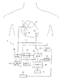
まず図1を参照すると、除細動閾値決定システムが符号10で示されている。このシステム10は、患者の心臓14またはその周辺に埋植され、心臓活性検出器16に接続された感知電極12を含む。「心臓またはその周辺」とは、患者の胸の皮下または外側を含むことを意味する。感知電極12の配置は、心臓の電気的活性が正確に表れるかぎり、決定的なものではない。一例として、感知電極は歩調取り・感知用のチップ電極であってもよい。
【0010】
心臓活性検出器16は、例えば、電極12で感知される信号の準位を増幅する増幅器を含む心電図検出器であってもよい。心臓活性検出器の目的は、心臓の電気的活性の受攻期の発生を決定することである。さらに2個の除細動電極18および20を心臓またはその周辺に埋植し、パルス発生器22に接続している。パルス発生器22は、刻時回路24を介して心臓活性検出器16に接続されている。
【0011】
心臓状態検出器26を心臓活性検出器16に接続し、心臓の機能状態をモニターする。パルス・エネルギー準位検出器28をパルス発生器22に接続し、心臓に印加されるショックのエネルギーの準位を選択する。パルス・エネルギー準位検出器28の数値は、表示装置30上で視覚的にモニターし、メモリー31に記憶させることができる。これらはいずれも検出器28に接続されている。また、図示するように、心臓状態検出器26が細動を検出する機能を観察者がなすこともできる。
【0012】
例えば患者の心臓にひとりでには適正に機能できないという理由から、本発明による手順の間に心臓を歩調取りしなければならないことがしばしばある。そのような患者に対処するため、本発明は歩調取り回路29を用いている。歩調取り回路29は、刻時回路24と、歩調取り・感知電極として作用する電極12とに接続されている。それに加え、セレクター25を設けて、歩調取り回路29を利用者の意のままに作動させることを可能にしている。この構成では、受攻期の発生は、心臓活性検出器16を用いることなく、歩調取り回路29から刻時回路24を介して直接判定される。
【0013】
システム10は次のように作動する。心臓が不整脈にはない場合には、心臓14の電気的活性は電極12を介して検出器16によって感知される。検出器16は、心臓の脱分極、すなわちQRS群を感知し、これが刻時回路24を起動する。刻時回路24は、検出器16によって起動されると、所定期間の時間遅延の後、パルス発生器22を起動して電極18と20との間で心臓14にショックを印加する。刻時回路24の時間遅延は、QRS群の発生とT波に相当する受攻期との間の時間差に相当する。
【0014】
あるいはまた、心臓が歩調取りを必要とする場合には、歩調取り回路29は電極12を介して心臓を歩調取りし、刻時回路24は歩調取り回路29によって起動されて、パルス発生器22によって心臓に印加されるショックを制御する。
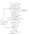
次に、図1,図2および図3を参照しながらシステム10の作動をより詳細に説明する。心臓が不整脈にはない場合、ステップ32において、心臓活性検出器16は心臓14の電気的活性を感知する。ステップ34においてQRS群の発生がいったん検出器16によって検出されると、刻時回路24が起動されて、心臓にショックを与えるまでの所定の時間遅延をステップ36で設定する。図示するように、歩調取りを必要とする心臓の場合は、ステップ32および34に代ってステツプ35が入る。時間遅延が終了すると、パルス発生器22が刻時回路24によって起動され、ステップ38において、T波の発生時に電極18および20を介して心臓にショックを印加する。
【0015】
まず、図3に示すように、心臓に印加されるショックのエネルギー準位E1は、細動を誘発しそうにない、比較的高いものである。ステップ39で、このエネルギー準位はメモリー31に記憶され、そして/あるいは、表示装置30に表示される。そしてステップ40で心臓状態検出器26が検出器16からの信号を判読して、心臓がパルス発生器22からのショックによって細動状態に置かれているかどうかをステップ42で決定する。心臓が細動状態になければ、パルス発生器によって印加される次のショックは、ステップ44において、パルス・エネルギー準位検出器・セレクター28により、より低いエネルギー準位、例えばE2にまで低減される。その後は、心臓が細動状態に置かれるまでステップ34〜42が繰返される。通常、ショックエネルギー準位の増分は5ジュール程度であり、ショックは、頂部を切り取った形の指数関数を示す、単相型または二相型の波形の電気パルスである。
【0016】
E4によって示すようにいったん心臓が細動状態に置かれると、ステップ46において、メモリー31に記憶された先のエネルギー準位E3が表示装置30上に表示される。エネルギー準位E3は、特定の誘導形状についての閾値除細動準位に相当する。そして、十分なエネルギー準位を有する除細動パルスを電極18および20を介して印加することにより、心臓が除細動される。
【0017】
【発明の効果】
上述のシステムにより、新たな除細動システムを埋植する際に患者が細動状態に置かれる回数が減少する。その結果、患者にとっての不必要な危険および損傷を回避することができる。
例えば心臓活性検出器16の機能と心臓状態検出器26の機能とを一つの装置に組み込むなどの変型は、本発明の範囲および制振の範囲内にあると考慮される。それに加え、本発明によるシステムを用いて、2個を越えるいかなる型の除細動電極、例えばパッチ型、コップ型およびカテーテル型の電極を有する誘導構造の閾値除細動エネルギーを決定することができる。
【0018】
上記の説明は例示のためのものに過ぎず、請求項によって述べたことを除き、本発明をいかなる方法においても限定することを意図したものではない。
【図面の簡単な説明】
【図1】特定の除細動装置が埋植されている特定の患者についての閾値除細動エネルギーを決定するための本発明によるシステムを示す略ブロック図である。
【図2】特定の患者にとって必要とされる除細動エネルギーを決定するための本発明による段階を示すブロック図である。
【図3】印加されたエネルギー準位と閾値除細動との関係を示す図である。[0001]
[Background Art]
The present invention relates to a system for determining the effective defibrillation energy released into an implantable fibrillation system without repeatedly inducing fibrillation of the patient's heart.
In the field of implantable defibrillation, the energy levels needed to defibrillate a patient's heart depend on the shape and location of the defibrillation guidance and the responsiveness of the particular patient's heart. is there. It is necessary to determine the lowest energy level required to defibrillate a patient's heart with the greatest accuracy.
[0002]
One known method of determining the defibrillation threshold energy of an implantable system is to induce fibrillation of the patient's heart. Once fibrillation occurs, the heart is defibrillated via an implanted defibrillation lead. Initially, defibrillation is attempted with a relatively high energy level. If this energy level defibrillates the heart, the heart is again placed in a defibrillation state and a defibrillation pulse having a lower energy level is applied to the heart. If the energy level defibrillates the heart, the process is repeated with a lower energy level defibrillation pulse until the heart is no longer defibrillated. Since the threshold does not actually exist, it is often repeated at the lowest energy that succeeds at the beginning of a defibrillation-defibrillation episode to infer the likelihood that the energy will work successfully. Finally, the defibrillation energy level of the permanently implanted device is set higher than the energy level that reliably defibrillated the heart, depending on the judgment of the physician.
[0003]
A disadvantage of the above-described method is that in order to determine the threshold of the system, fibrillation of the heart must be repeatedly triggered and the heart must be repeatedly defibrillated.
[0004]
[Object of the invention]
It is a primary object of the present invention to overcome the above-mentioned problems by determining the minimum defibrillation energy required by an implantation system without repeatedly inducing fibrillation of the patient's heart. .
A further object of the present invention, by providing a shock to the heart during the vulnerable period indicated by the signal representing the electrical activity of the heart, is to determine the constant minimum defibrillation energy.
[0005]
Configuration of the Invention
The present invention senses a cardiac depolarization (QRS complex) that is not in arrhythmia and, after a predetermined period of time, shocks the heart when a vulnerable period occurs, thereby removing the patient's heart by an implantable system. the minimum defibrillation energy required to fibrillation to a system and method for determine a constant.
[0006]
Effect of the Invention
Specifically, shocks of different intensities are applied to the heart during the T-wave period known as the vulnerable period. Alternatively, the heart may be paced to determine the occurrence of the vulnerable period without detecting the QRS complex. Rather, if the heart is paced, controlling its pacing will accurately predict the onset of the vulnerable period.
[0007]
Shock of sufficient intensity induces ventricular fibrillation, but increasing the intensity to a higher range will result in the shock reaching a level or intensity that no longer causes ventricular fibrillation. The lowest intensity in the high range that cannot defibrillate the heart correlates with the intensity required to defibrillate the heart. As such, the method can avoid repetitive fibrillation of the heart.
[0008]
The above and other objects and advantages will be more clearly understood by referring to the following description, taken in conjunction with the accompanying drawings.
[0009]
【Example】
Referring first to FIG. 1, a defibrillation threshold determination system is indicated generally by the
[0010]
[0011]
The
[0012]
Often, the heart must be paced during the procedure according to the invention, for example because it cannot function properly on the patient's heart alone. To address such patients, the present invention uses a
[0013]
[0014]
Alternatively, if the heart requires pacing, pacing
Next, the operation of the
[0015]
First, as shown in FIG. 3, the energy level E 1 of the shock applied to the heart, unlikely to induce fibrillation is relatively high. At
[0016]
Once the heart has been placed in the fibrillation state, as indicated by E 4 , the previous energy level E 3 stored in the
[0017]
【The invention's effect】
The above-described system reduces the number of times a patient is placed in defibrillation when implanting a new defibrillation system. As a result, unnecessary danger and damage to the patient can be avoided.
Variations such as, for example, incorporating the functions of the
[0018]
The above description is by way of example only and is not intended to limit the invention in any manner, except as indicated by the claims.
[Brief description of the drawings]
FIG. 1 is a schematic block diagram illustrating a system according to the present invention for determining a threshold defibrillation energy for a particular patient having a particular defibrillator implanted therein.
FIG. 2 is a block diagram illustrating the steps according to the present invention for determining the defibrillation energy required for a particular patient.
FIG. 3 is a diagram showing a relationship between an applied energy level and threshold defibrillation.
Claims (10)
心臓の電気的活性を感知するための感知手段と、
感知された心臓の該電気的活性に基づいて心臓の電気的事象を検出し、該電気的活性の受攻期を決定するための、該感知手段に接続された検出手段と、
心臓の電気的活性の受攻期間中に電気パルスを発生し、該除細動電極を介してその電気パルスを心臓に印加するための、該検出手段に接続されたパルス発生手段と、
該パルス発生手段によって発生かつ、印加された電気パルスのエネルギー準位を制御するための、該パルス発生手段に接続されたパルスエネルギー準位検出・選択手段と、
パルス発生手段によって印加された電気パルスのエネルギー準位を記憶するためのメモリー手段と、
前記除細動閾値エネルギー準位を判定する判定手段とを含み、
該パルス発生手段が、所定の初期エネルギーをもって最初の電気パルスを心臓に印加し、該エネルギー準位検出・選択手段の制御のもと、エネルギーを低減させながら、後続する電気パルスを続けて心臓に印加し、心臓に細動を誘発させたことを該検出手段が判定するまでこれを繰返し、前記判定手段が心臓に細動を誘発させたことを該検出手段が判定すると、心臓に細動を誘発させた電気パルスの直前の電気パルスのエネルギー準位に基づいて、前記除細動閾値エネルギー準位を判定することを特徴とするシステム。Is set embedded in the body of a patient, a system for determining the defibrillation threshold energy level of the defibrillation induction system comprising at least two defibrillation electrodes set embedded in the heart or around,
Sensing means for sensing the electrical activity of the heart;
Detecting means connected to the sensing means for detecting an electrical event of the heart based on the electrical activity of the sensed heart and determining a vulnerable period of the electrical activity;
Pulse generating means connected to the detection means for generating an electric pulse during a period of receiving the electrical activity of the heart and applying the electric pulse to the heart via the defibrillation electrode;
A pulse energy level detection / selection unit connected to the pulse generation unit, for controlling the energy level of the electric pulse generated and applied by the pulse generation unit,
Memory means for storing the energy level of the electric pulse applied by the pulse generating means,
Determining means for determining the defibrillation threshold energy level,
The pulse generating means applies a first electric pulse to the heart with a predetermined initial energy, and under the control of the energy level detection / selection means, while reducing the energy, continues the subsequent electric pulse to the heart. This is repeated until the detecting means determines that fibrillation has been induced in the heart.If the detecting means determines that the determining means has induced fibrillation in the heart, the heart is subjected to fibrillation. Determining a defibrillation threshold energy level based on an energy level of an electrical pulse immediately before the induced electrical pulse.
心臓またはその周辺に取り付けられた除細動電極と、
患者の心臓の電気的活性を感知して患者の心電図を判定する、心臓またはその周辺に取り付けられた感知電極手段と、
該心電図からの受攻期を判定するための手段と、
該受攻期間中にエネルギー準位が低減してゆくショックを該除細動電極を介して心臓に印加するための手段と、
該印加手段によって印加された該ショックが患者の心臓に心室細動を誘発させたかどうかを感知、判定するための手段と、
心室細動を誘発することができなかったショックのエネルギー準位のうちもっとも低いものであって、心室細動を誘発したショックのエネルギー準位よりもすぐ上のエネルギー準位を前記除細動閾値エネルギー準位の指標として記憶するための手段とを含むことを特徴とするシステム。A system for determining a defibrillation threshold energy of a defibrillation guidance system,
A defibrillation electrode attached to or around the heart;
Sensing electrode means mounted on or around the heart for sensing the electrical activity of the patient's heart to determine the patient's electrocardiogram;
Means for determining a vulnerable period from the electrocardiogram;
Means for applying a shock of decreasing energy level to the heart via the defibrillation electrode during the attack period;
Means for sensing and determining whether the shock applied by the applying means has induced ventricular fibrillation in the patient's heart;
The lowest energy level of the shock that failed to induce ventricular fibrillation, the energy level immediately above the energy level of the shock that induced ventricular fibrillation, Means for storing as an indication of the energy level.
心臓の電気的活性を感知するための感知手段と、
歩調取り手段および、歩調取り電気信号を心臓に印加するための、該歩調取り手段に接続された歩調取り電極と、
感知された心臓の該電気的活性に基づいて心臓の電気的事象を検出するための、該感知手段に接続された検出手段と、
心臓の電気的活性の受攻期間中に電気パルスを発生し、該除細動電極を介してその電気パルスを心臓に印加するための、該検出手段に接続されたパルス発生手段と、
該パルス発生手段によって発生、印加された電気パルスのエネルギー準位を制御するための、該パルス発生手段に接続されたパルスエネルギー準位検出・選択手段と、
パルス発生手段によって印加された電気パルスのエネルギー準位を記憶するためのメモリー手段と、
前記除細動閾値エネルギー準位を判定する判定手段とを含み、
該パルス発生手段が、所定の初期エネルギーをもって最初の電気パルスを心臓に印加し、該パルスエネルギー準位検出・選択手段の制御のもと、エネルギーを低減させながら、後続する電気パルスを続けて心臓に印加し、心臓に細動を誘発させたことを該検出手段が判定するまでこれを繰り返し、心臓に細動を誘発させたことを該検出手段が判定すると、前記判定手段が心臓に細動を誘発させた電気パルスの直前の、それよりもすぐ上の電気パルスのエネルギー準位に基づいて、前記除細動誘導系の除細動閾値エネルギーと判定することを特徴とするシステム。Is set embedded in the body of a patient, a system for determining the defibrillation threshold energy level cardioversion induction system comprising at least two defibrillation electrodes set embedded in the heart or around,
Sensing means for sensing the electrical activity of the heart;
Pacing means, and a pacing electrode connected to the pacing means for applying a pacing electrical signal to the heart;
Detecting means coupled to the sensing means for detecting a cardiac electrical event based on the sensed electrical activity of the heart;
Pulse generating means connected to the detection means for generating an electric pulse during a period of receiving the electrical activity of the heart and applying the electric pulse to the heart via the defibrillation electrode;
A pulse energy level detection / selection unit connected to the pulse generation unit for controlling the energy level of the electric pulse generated and applied by the pulse generation unit;
Memory means for storing the energy level of the electric pulse applied by the pulse generating means,
Determining means for determining the defibrillation threshold energy level,
The pulse generating means applies a first electric pulse to the heart with a predetermined initial energy, and under the control of the pulse energy level detecting / selecting means, continues the subsequent electric pulse while reducing the energy. This is repeated until the detecting means determines that fibrillation has been induced in the heart. When the detecting means determines that fibrillation has been induced in the heart, the determining means determines that the heart has fibrillated. Determining the defibrillation threshold energy of the defibrillation guidance system based on the energy level of the electric pulse immediately before and immediately above the electric pulse that induced the defibrillation.
Applications Claiming Priority (2)
| Application Number | Priority Date | Filing Date | Title |
|---|---|---|---|
| US07/571234 | 1990-08-23 | ||
| US07/571,234 US5105809A (en) | 1990-08-23 | 1990-08-23 | System and method for evaluating lead defibrillation requirements of an implanted device without repeated fibrillation induction |
Related Child Applications (1)
| Application Number | Title | Priority Date | Filing Date |
|---|---|---|---|
| JP2003351267A Division JP2004105745A (en) | 1990-08-23 | 2003-10-09 | System and method for evaluating demand reference of induced defibrillation of device implanted without repeated induction of fibrillation |
Publications (2)
| Publication Number | Publication Date |
|---|---|
| JPH06165828A JPH06165828A (en) | 1994-06-14 |
| JP3592340B2 true JP3592340B2 (en) | 2004-11-24 |
Family
ID=24282854
Family Applications (2)
| Application Number | Title | Priority Date | Filing Date |
|---|---|---|---|
| JP21221091A Expired - Fee Related JP3592340B2 (en) | 1990-08-23 | 1991-08-23 | System and method for evaluating guided defibrillation requirements of an implanted device without repeatedly inducing fibrillation |
| JP2003351267A Pending JP2004105745A (en) | 1990-08-23 | 2003-10-09 | System and method for evaluating demand reference of induced defibrillation of device implanted without repeated induction of fibrillation |
Family Applications After (1)
| Application Number | Title | Priority Date | Filing Date |
|---|---|---|---|
| JP2003351267A Pending JP2004105745A (en) | 1990-08-23 | 2003-10-09 | System and method for evaluating demand reference of induced defibrillation of device implanted without repeated induction of fibrillation |
Country Status (6)
| Country | Link |
|---|---|
| US (1) | US5105809A (en) |
| EP (1) | EP0473002B1 (en) |
| JP (2) | JP3592340B2 (en) |
| CA (1) | CA2049665C (en) |
| DE (1) | DE69115384T2 (en) |
| HK (1) | HK1007694A1 (en) |
Families Citing this family (32)
| Publication number | Priority date | Publication date | Assignee | Title |
|---|---|---|---|---|
| DE4111478A1 (en) * | 1991-04-09 | 1992-10-15 | Siemens Ag | IMPLANTABLE DEFIBRILLATOR |
| US5215083A (en) * | 1991-10-07 | 1993-06-01 | Telectronics Pacing Systems, Inc. | Apparatus and method for arrhythmia induction in arrhythmia control system |
| US5439481A (en) * | 1992-02-26 | 1995-08-08 | Angeion Corporation | Semi-automatic atrial and ventricular cardioverter defibrillator |
| US5269298A (en) * | 1992-10-23 | 1993-12-14 | Incontrol, Inc. | Atrial defibrillator and method for providing synchronized delayed cardioversion |
| US5346506A (en) * | 1992-11-10 | 1994-09-13 | Mower Morton M | Method for establishing defibrillation threshold for a cardiac defibrillator |
| US5395373A (en) * | 1993-01-07 | 1995-03-07 | Incontrol, Inc. | Atrial defibrillator and method for setting energy threshold values |
| US5411539A (en) * | 1993-08-31 | 1995-05-02 | Medtronic, Inc. | Active can emulator and method of use |
| US5531770A (en) * | 1993-09-03 | 1996-07-02 | Angeion Corporation | Device and method for determining defibrillation thresholds |
| FR2710848B1 (en) * | 1993-10-08 | 1995-12-01 | Ela Medical Sa | Implantable defibrillator with optically isolated shock generator. |
| US5564422A (en) * | 1995-04-03 | 1996-10-15 | Chen; Peng-Sheng | Method and apparatus for improved prediction of transvenous defibrillation threshold |
| US5666958A (en) * | 1995-04-06 | 1997-09-16 | Rothenberg; Peter M. | Interface module for electrically connecting medical equipment |
| US5662696A (en) * | 1995-09-28 | 1997-09-02 | Angeion Corp | One piece disposable threshold test can electrode for use with an implantable cardioverter defibrillator system |
| US5609618A (en) * | 1995-12-06 | 1997-03-11 | Ventritex, Inc. | Apparatus and method for inducing fibrillation |
| US5653740A (en) * | 1996-01-16 | 1997-08-05 | Medtronic, Inc. | Method and apparatus for induction of fibrillation |
| US5954753A (en) * | 1997-06-12 | 1999-09-21 | Sulzer Intermedics, Inc. | Implantable defibrillator with improved testing of capability to defibrillate |
| US6829505B2 (en) * | 2000-12-26 | 2004-12-07 | Cardiac Pacemakers, Inc. | System and method for cardiac rhythm management with synchronized pacing protection period |
| US7003347B2 (en) * | 2000-12-26 | 2006-02-21 | Cardiac Pacemakers, Inc. | System and method for cardiac rhythm management with dynamically adjusted synchronized chamber pacing protection period |
| US8150510B2 (en) * | 2002-04-15 | 2012-04-03 | Imperception, Inc. | Shock timing technology |
| US6675042B2 (en) * | 2002-04-15 | 2004-01-06 | Charles D. Swerdlow | Defibrillation shock strength determination technology |
| US8831722B2 (en) | 2002-04-15 | 2014-09-09 | Imperception, Inc. | Shock timing technology |
| US7319898B2 (en) * | 2003-04-25 | 2008-01-15 | Medtronic, Inc. | Self-adapting defibrillator induction feature |
| US7181275B2 (en) * | 2003-12-23 | 2007-02-20 | Medtronic, Inc. | Method and apparatus for actively determining a coupling interval corresponding to a cardiac vulnerable zone |
| US7711425B2 (en) * | 2005-08-22 | 2010-05-04 | Cardiac Pacemakers, Inc. | Defibrillation threshold prediction methods and systems |
| US7421300B2 (en) * | 2005-10-31 | 2008-09-02 | Medtronic, Inc. | Implantation of medical device with measurement of body surface potential |
| US8064996B2 (en) * | 2007-10-03 | 2011-11-22 | Medtronic, Inc. | Automatic determination of T-shock vulnerable window |
| US8644923B2 (en) * | 2008-07-24 | 2014-02-04 | Medtronic, Inc. | Determination of upper limit of vulnerability using a variable number of shocks |
| US8565865B2 (en) * | 2008-07-24 | 2013-10-22 | Medtronic, Inc. | Methods for the determination of T-shock vulnerable window from far-field electrograms in implantable cardioverter defibrillators |
| US8560064B2 (en) * | 2008-07-31 | 2013-10-15 | Medtronic, Inc. | Extravascular arrhythmia induction |
| US8359094B2 (en) * | 2008-07-31 | 2013-01-22 | Medtronic, Inc. | Extravascular arrhythmia induction |
| US20100069979A1 (en) * | 2008-09-12 | 2010-03-18 | Pittaro Michael R | Methods for Determining a Vulnerable Window for the Induction of Fibrillation |
| US10946207B2 (en) | 2017-05-27 | 2021-03-16 | West Affum Holdings Corp. | Defibrillation waveforms for a wearable cardiac defibrillator |
| WO2023172961A1 (en) * | 2022-03-10 | 2023-09-14 | Zoll Medical Corporation | Baselining therapy energy for wearable cardiac treatment devices |
Family Cites Families (5)
| Publication number | Priority date | Publication date | Assignee | Title |
|---|---|---|---|---|
| US4094310A (en) * | 1976-10-04 | 1978-06-13 | American Optical Corporation | Apparatus for enhanced display of physiological waveforms and for defibrillation |
| US4114628A (en) * | 1977-05-31 | 1978-09-19 | Rizk Nabil I | Demand pacemaker with self-adjusting threshold and defibrillating feature |
| US4273132A (en) * | 1978-11-06 | 1981-06-16 | Medtronic, Inc. | Digital cardiac pacemaker with threshold margin check |
| DE3064258D1 (en) * | 1979-07-19 | 1983-08-25 | Medtronic Inc | Implantable cardioverter |
| EP0303939A1 (en) * | 1987-08-21 | 1989-02-22 | Siemens Aktiengesellschaft | Current stimulating device for constant voltage operation |
-
1990
- 1990-08-23 US US07/571,234 patent/US5105809A/en not_active Expired - Lifetime
-
1991
- 1991-08-13 EP EP91113597A patent/EP0473002B1/en not_active Expired - Lifetime
- 1991-08-13 DE DE69115384T patent/DE69115384T2/en not_active Expired - Lifetime
- 1991-08-22 CA CA002049665A patent/CA2049665C/en not_active Expired - Fee Related
- 1991-08-23 JP JP21221091A patent/JP3592340B2/en not_active Expired - Fee Related
-
1998
- 1998-06-26 HK HK98106888A patent/HK1007694A1/en not_active IP Right Cessation
-
2003
- 2003-10-09 JP JP2003351267A patent/JP2004105745A/en active Pending
Also Published As
| Publication number | Publication date |
|---|---|
| CA2049665A1 (en) | 1992-02-24 |
| EP0473002A2 (en) | 1992-03-04 |
| EP0473002B1 (en) | 1995-12-13 |
| US5105809A (en) | 1992-04-21 |
| DE69115384T2 (en) | 1996-06-20 |
| JPH06165828A (en) | 1994-06-14 |
| DE69115384D1 (en) | 1996-01-25 |
| CA2049665C (en) | 2001-03-06 |
| EP0473002A3 (en) | 1992-05-13 |
| HK1007694A1 (en) | 1999-04-23 |
| JP2004105745A (en) | 2004-04-08 |
Similar Documents
| Publication | Publication Date | Title |
|---|---|---|
| JP3592340B2 (en) | System and method for evaluating guided defibrillation requirements of an implanted device without repeatedly inducing fibrillation | |
| JP4537442B2 (en) | Method of operating an active implantable medical device | |
| US6539254B1 (en) | Implantable ventricular cardioverter/defibrillator employing atrial pacing for preventing atrial fibrillation from ventricular cardioversion and defibrillation shocks | |
| US5346506A (en) | Method for establishing defibrillation threshold for a cardiac defibrillator | |
| JP2563748B2 (en) | Atrial defibrillator | |
| US6052617A (en) | System and method for reliably detecting atrial events of a heart using only atrial sensing | |
| EP0642370B1 (en) | Combination pacemaker and defibrillator | |
| US6041251A (en) | System and method for detecting atrial events of a heart | |
| US6775572B2 (en) | Method and system for automatic anti-tachycardia pacing | |
| US5951593A (en) | Apparatus for preventing atrial fibrillation using precursors | |
| JPH09644A (en) | Implantable heart stimulating device | |
| US5564422A (en) | Method and apparatus for improved prediction of transvenous defibrillation threshold | |
| EP1503824B1 (en) | Task-oriented induction capabilities for icds and programmers | |
| EP1713538B1 (en) | Determining a coupling interval for a cardiac vulnerable zone | |
| US7319898B2 (en) | Self-adapting defibrillator induction feature |
Legal Events
| Date | Code | Title | Description |
|---|---|---|---|
| A131 | Notification of reasons for refusal |
Free format text: JAPANESE INTERMEDIATE CODE: A131 Effective date: 20040517 |
|
| A521 | Written amendment |
Free format text: JAPANESE INTERMEDIATE CODE: A523 Effective date: 20040721 |
|
| TRDD | Decision of grant or rejection written | ||
| A01 | Written decision to grant a patent or to grant a registration (utility model) |
Free format text: JAPANESE INTERMEDIATE CODE: A01 Effective date: 20040817 |
|
| A61 | First payment of annual fees (during grant procedure) |
Free format text: JAPANESE INTERMEDIATE CODE: A61 Effective date: 20040825 |
|
| R150 | Certificate of patent or registration of utility model |
Free format text: JAPANESE INTERMEDIATE CODE: R150 |
|
| A521 | Written amendment |
Free format text: JAPANESE INTERMEDIATE CODE: A523 Effective date: 20040929 |
|
| R154 | Certificate of patent or utility model (reissue) |
Free format text: JAPANESE INTERMEDIATE CODE: R154 |
|
| FPAY | Renewal fee payment (event date is renewal date of database) |
Free format text: PAYMENT UNTIL: 20080903 Year of fee payment: 4 |
|
| LAPS | Cancellation because of no payment of annual fees |