JP3589372B2 - Data multiplexing method - Google Patents
Data multiplexing method Download PDFInfo
- Publication number
- JP3589372B2 JP3589372B2 JP14535996A JP14535996A JP3589372B2 JP 3589372 B2 JP3589372 B2 JP 3589372B2 JP 14535996 A JP14535996 A JP 14535996A JP 14535996 A JP14535996 A JP 14535996A JP 3589372 B2 JP3589372 B2 JP 3589372B2
- Authority
- JP
- Japan
- Prior art keywords
- time
- multiplexed
- stream
- buffer
- multiplexed stream
- Prior art date
- Legal status (The legal status is an assumption and is not a legal conclusion. Google has not performed a legal analysis and makes no representation as to the accuracy of the status listed.)
- Expired - Fee Related
Links
Images


Classifications
-
- H—ELECTRICITY
- H04—ELECTRIC COMMUNICATION TECHNIQUE
- H04N—PICTORIAL COMMUNICATION, e.g. TELEVISION
- H04N21/00—Selective content distribution, e.g. interactive television or video on demand [VOD]
- H04N21/20—Servers specifically adapted for the distribution of content, e.g. VOD servers; Operations thereof
- H04N21/23—Processing of content or additional data; Elementary server operations; Server middleware
- H04N21/234—Processing of video elementary streams, e.g. splicing of video streams, manipulating MPEG-4 scene graphs
- H04N21/23406—Processing of video elementary streams, e.g. splicing of video streams, manipulating MPEG-4 scene graphs involving management of server-side video buffer
-
- H—ELECTRICITY
- H04—ELECTRIC COMMUNICATION TECHNIQUE
- H04N—PICTORIAL COMMUNICATION, e.g. TELEVISION
- H04N21/00—Selective content distribution, e.g. interactive television or video on demand [VOD]
- H04N21/20—Servers specifically adapted for the distribution of content, e.g. VOD servers; Operations thereof
- H04N21/23—Processing of content or additional data; Elementary server operations; Server middleware
- H04N21/236—Assembling of a multiplex stream, e.g. transport stream, by combining a video stream with other content or additional data, e.g. inserting a URL [Uniform Resource Locator] into a video stream, multiplexing software data into a video stream; Remultiplexing of multiplex streams; Insertion of stuffing bits into the multiplex stream, e.g. to obtain a constant bit-rate; Assembling of a packetised elementary stream
- H04N21/2368—Multiplexing of audio and video streams
-
- H—ELECTRICITY
- H04—ELECTRIC COMMUNICATION TECHNIQUE
- H04N—PICTORIAL COMMUNICATION, e.g. TELEVISION
- H04N21/00—Selective content distribution, e.g. interactive television or video on demand [VOD]
- H04N21/40—Client devices specifically adapted for the reception of or interaction with content, e.g. set-top-box [STB]; Operations thereof
- H04N21/43—Processing of content or additional data, e.g. demultiplexing additional data from a digital video stream; Elementary client operations, e.g. monitoring of home network or synchronising decoder's clock; Client middleware
- H04N21/434—Disassembling of a multiplex stream, e.g. demultiplexing audio and video streams, extraction of additional data from a video stream; Remultiplexing of multiplex streams; Extraction or processing of SI; Disassembling of packetised elementary stream
- H04N21/4341—Demultiplexing of audio and video streams
-
- H—ELECTRICITY
- H04—ELECTRIC COMMUNICATION TECHNIQUE
- H04N—PICTORIAL COMMUNICATION, e.g. TELEVISION
- H04N21/00—Selective content distribution, e.g. interactive television or video on demand [VOD]
- H04N21/40—Client devices specifically adapted for the reception of or interaction with content, e.g. set-top-box [STB]; Operations thereof
- H04N21/43—Processing of content or additional data, e.g. demultiplexing additional data from a digital video stream; Elementary client operations, e.g. monitoring of home network or synchronising decoder's clock; Client middleware
- H04N21/44—Processing of video elementary streams, e.g. splicing a video clip retrieved from local storage with an incoming video stream, rendering scenes according to MPEG-4 scene graphs
- H04N21/44004—Processing of video elementary streams, e.g. splicing a video clip retrieved from local storage with an incoming video stream, rendering scenes according to MPEG-4 scene graphs involving video buffer management, e.g. video decoder buffer or video display buffer
-
- H—ELECTRICITY
- H04—ELECTRIC COMMUNICATION TECHNIQUE
- H04N—PICTORIAL COMMUNICATION, e.g. TELEVISION
- H04N9/00—Details of colour television systems
- H04N9/79—Processing of colour television signals in connection with recording
- H04N9/80—Transformation of the television signal for recording, e.g. modulation, frequency changing; Inverse transformation for playback
- H04N9/804—Transformation of the television signal for recording, e.g. modulation, frequency changing; Inverse transformation for playback involving pulse code modulation of the colour picture signal components
- H04N9/8042—Transformation of the television signal for recording, e.g. modulation, frequency changing; Inverse transformation for playback involving pulse code modulation of the colour picture signal components involving data reduction
-
- H—ELECTRICITY
- H04—ELECTRIC COMMUNICATION TECHNIQUE
- H04N—PICTORIAL COMMUNICATION, e.g. TELEVISION
- H04N5/00—Details of television systems
- H04N5/76—Television signal recording
- H04N5/84—Television signal recording using optical recording
- H04N5/85—Television signal recording using optical recording on discs or drums
-
- H—ELECTRICITY
- H04—ELECTRIC COMMUNICATION TECHNIQUE
- H04N—PICTORIAL COMMUNICATION, e.g. TELEVISION
- H04N9/00—Details of colour television systems
- H04N9/79—Processing of colour television signals in connection with recording
- H04N9/80—Transformation of the television signal for recording, e.g. modulation, frequency changing; Inverse transformation for playback
- H04N9/804—Transformation of the television signal for recording, e.g. modulation, frequency changing; Inverse transformation for playback involving pulse code modulation of the colour picture signal components
- H04N9/806—Transformation of the television signal for recording, e.g. modulation, frequency changing; Inverse transformation for playback involving pulse code modulation of the colour picture signal components with processing of the sound signal
- H04N9/8063—Transformation of the television signal for recording, e.g. modulation, frequency changing; Inverse transformation for playback involving pulse code modulation of the colour picture signal components with processing of the sound signal using time division multiplex of the PCM audio and PCM video signals
-
- H—ELECTRICITY
- H04—ELECTRIC COMMUNICATION TECHNIQUE
- H04N—PICTORIAL COMMUNICATION, e.g. TELEVISION
- H04N9/00—Details of colour television systems
- H04N9/79—Processing of colour television signals in connection with recording
- H04N9/80—Transformation of the television signal for recording, e.g. modulation, frequency changing; Inverse transformation for playback
- H04N9/82—Transformation of the television signal for recording, e.g. modulation, frequency changing; Inverse transformation for playback the individual colour picture signal components being recorded simultaneously only
- H04N9/8205—Transformation of the television signal for recording, e.g. modulation, frequency changing; Inverse transformation for playback the individual colour picture signal components being recorded simultaneously only involving the multiplexing of an additional signal and the colour video signal
- H04N9/8233—Transformation of the television signal for recording, e.g. modulation, frequency changing; Inverse transformation for playback the individual colour picture signal components being recorded simultaneously only involving the multiplexing of an additional signal and the colour video signal the additional signal being a character code signal
-
- H—ELECTRICITY
- H04—ELECTRIC COMMUNICATION TECHNIQUE
- H04N—PICTORIAL COMMUNICATION, e.g. TELEVISION
- H04N9/00—Details of colour television systems
- H04N9/79—Processing of colour television signals in connection with recording
- H04N9/87—Regeneration of colour television signals
- H04N9/877—Regeneration of colour television signals by assembling picture element blocks in an intermediate memory
Landscapes
- Engineering & Computer Science (AREA)
- Multimedia (AREA)
- Signal Processing (AREA)
- Compression Or Coding Systems Of Tv Signals (AREA)
- Signal Processing For Digital Recording And Reproducing (AREA)
- Television Signal Processing For Recording (AREA)
- Time-Division Multiplex Systems (AREA)
Description
【0001】
本発明は、データ多重化方法に関し、例えば、複数の映像信号や音声信号等からなる複数の多重化ストリームを復号装置に入力し、切り替えて再生するとき、復号装置のバッファメモリが破綻を起こさないようにすることができるようにしたデータ多重化方法に関する。
【0002】
【従来の技術】
図12は、映像や音声等の信号を送受信する送受信システムの構成例を示している。送信側(符号化装置)においては、ビデオエンコーダ(符号化器)1は、入力された映像信号を符号化するようになされている。オーディオエンコーダ2は、入力された音声信号を符号化するようになされている。多重化器3は、ビデオエンコーダ1およびオーディオエンコーダ2より供給された符号化されたビデオデータおよびオーディオデータを多重化するようになされている。
【0003】
多重化器3において多重化された信号は、記録可能なDVD(Digital Versatile Disc)等の記録媒体4に記録されるか、または伝送路5に送出されるようになされている。
【0004】
受信側(復号化装置)においては、分離器6は、記録媒体4または伝送路5を介して供給された符号化され、多重化されたデータを、ビデオデータやオーディオデータなどに種類別に分離するようになされている。ビデオデコーダ7は、分離器6より供給された符号化されたビデオデータを復号化した後、出力するようになされている。オーディオデコーダ8は、分離器6より供給された符号化されたオーディオデータを復号化した後、出力するようになされている。
【0005】
例えば、送信側において、入力された映像や音声などの信号は、ビデオエンコーダ1およびオーディオエンコーダ2においてそれぞれ符号化された後、多重化器3に供給される。多重化器3に供給された符号化されたビデオデータおよびオーディオデータは、多重化(1本化)された後、記録媒体4に供給され、記録されるか、または伝送路5に送出され、受信側に伝送される。
【0006】
受信側において、記録媒体4に記録された符号化され、多重化されたビデオデータおよびオーディオデータ、または伝送路5を介して伝送されてきた符号化され、多重化されたビデオデータおよびオーディオデータは、分離器6に供給され、映像や音声等の種類別に分離される。即ち、ビデオデータおよびオーディオデータが再構成される。再構成されたビデオデータは、ビデオデコーダ7に供給され、復号化される。また、再構成されたオーディオデータは、オーディオデコーダ8に供給され、復号化される。復号化されたビデオデータおよびオーディオデータは、同期して出力される。
【0007】
MPEG(Moving Picture Experts Group)システム(ISO/IEC 13818−1およびISO/IEC 11172−1)は、上述したような映像や音声等の符号化データを多重および分離する方式に関する国際規格である。以下では、映像や音声等の符号化データをエレメンタリーストリームと呼ぶことにする。また、特に、映像信号の符号化データをビデオストリーム、音声信号の符号化データをオーディオストリームと呼ぶことにする。さらに、それらの複数のエレメンタリーストリームを多重化したデータを多重化ストリームと呼ぶことにする。
【0008】
また、以下では、簡単のため、多重化ストリームとして、MPEG1(ISO/IEC11172−1)システムストリーム、およびMPEG2(ISO/IEC 13818−1)プログラムストリームのみについてふれるが、MPEG2トランスポートストリームに応用することも可能である。
【0009】
図13は、MPEGシステムにおいて規定される多重化ストリームの構造を示す図である。同図に示すように、多重化ストリームは複数のパックから構成される。各パックには、パックヘッダが付加され、その中には、後述するSCR(System Clock Reference)や多重化レート(Mux_rate)等の情報が記述される。各パックは複数のパケットから構成され、個々のパックの中に、ビデオやオーディオ等のエレメンタリーストリームが分割されて挿入される。各パケットにはパケットヘッダが付加され、その中には後述するタイムスタンプ等が記述される。
【0010】
図14は、MPEGシステムにおいて規定される多重化ストリームの分離方法が適用される復号化装置の構成例を示している。この分離方法は、仮想的なデコーダを用いた方法であり、STD(System Target Decoder)モデルと呼ばれる。以下、その動作について説明する。
【0011】
STDモデルにおいては、その内部に基準クロックSTC(System Time Clock)11を有しており、STC11は、一定の周期で増加する。また、STDモデルに入力される多重化ストリームの各パックヘッダには、SCR(System Clock Reference)と呼ばれるシステム時刻参照値が記述されている。
【0012】
STDモデルへの多重化ストリームの入力は、STCとSCRによって制御される。即ち、読み込まれたSCRの値がSTCの値と等しくなった瞬間、そのSCRがパックヘッダに記述されたパックの入力が開始される。そのときの入力速度は、多重化レートと呼ばれ、各パックヘッダ内に記述される。
【0013】
分離器12においては、入力された個々のパック内の複数のパケットがその種類(例えば、ビデオストリームやオーディオストリーム等)に応じて分類され、ビデオストリームはバッファ(復号バッファ)13に、オーディオストリームはバッファ(復号バッファ)14に供給される。
【0014】
バッファ13,14に供給され、蓄積されたビデオストリームやオーディオストリーム等のデータは、アクセスユニット(Access Unit:エレメンタリーストリームの復号単位)毎に、パケットヘッダ内に記述された時刻情報(タイムスタンプ:Time Stamp)に基づいて出力され、ビデオデコーダ15およびオーディオデコーダ16においてそれぞれ復号化され、再生出力される。以下では、ビデオデコーダ15とオーディオデコーダ16とを特に区別する必要がないとき、適宜、単にデコーダ15,16と記載することにする。
【0015】
タイムスタンプには、DTS(Decoding Time−Stamp)およびPTS(Presentation Time−Stamp)が存在し、DTSはバッファ13,14からアクセスユニットが出力され、デコーダ15,16において復号される時刻を示し、PTSは復号されたアクセスユニットが再生出力される時刻を示している。そして、復号および出力のタイミングは、DTSおよびPTSの値とSTCの値を比較することにより制御される。ただし、各アクセスユニットのバッファ13,14からの転送およびデコーダ15,16での復号において遅延はなく、それぞれ瞬時に行われるものとする。
【0016】
一般に、所定のエレメンタリーストリームにおいて、DTSとPTSの値が等しい場合、パケットヘッダにはPTSのみが記述される。例えば、MPEGオーディオ(ISO/IEC 13818−3 および ISO/IEC 11172−3)がこれに該当する。また、MPEGビデオ(ISO/IEC 13818−2 および ISO/IEC 11172−2)は、アクセスユニットの種類により復号遅延が存在するので、その場合には、DTSおよびPTSの両方のタイムスタンプが記述される。再配列バッファ17は、IピクチャとPピクチャを一時的に記憶し、遅延制御を行ってデータの再配列を行うためのバッファである。
【0017】
SCRの値は、符号化装置(多重化器を含む)内の基準クロック(タイムベース)のサンプル値であり、これを用いて復号装置(STDモデル)の各バッファ(この場合、バッファ13,14)における入出力制御が可能となる。即ち、全てのバッファにおいて、オーバーフロー(バッファに供給されるデータがバッファ容量を超過すること)およびアンダーフロー(アクセスユニットが復号されるべき時刻にバッファに全て到達していないこと)することなく、STDモデルにおいて復号されるように、符号化装置においてSCRの値を適当に設定することが要求される。
【0018】
上述した多重化ストリームを複数個用いた応用例として、例えば「複数経路再生」が挙げられる。複数経路再生とは、例えば「Language Credit(言語に依存した映像再生)」、「Director’s Cut(映画監督が指示したカット:Parental Lockなど)」、あるいは「Multi−angles(複数のカメラで撮影された映像)」等を行う機能であり、単一のアプリケーションにおいて、ユーザの選択により複数の経路再生を実現するものである。
【0019】
図15は、複数経路再生の一例を示したものである。この例では、3種類の再生経路が存在し、図中の矢印はその中の1種類(再生経路3)を選択して再生を行う場合を示している。各再生経路は、各々独立したタイムベースに基づいて生成された複数の多重化ストリームから構成される。また、多重化ストリームMBaおよびMBcは全ての再生経路において共通であり、その中間部においてMBb(1)乃至MBb(3)の3つの多重化ストリームが選択可能である。例えば、再生経路1は、MBa,MBb(1),MBcの3つの多重化ストリームの連続再生によって構成される。再生経路2および3の場合についても同様である。
【0020】
図15の複数経路再生における各多重化ストリームは、例えば図16に示すような配置および順序で記録伝送される。このとき、復号化装置は、選択されている再生経路に基づいて、各多重化ストリーム単位に入力を制御する。図16は、図15において再生経路2が選択されたときの再生順序の例を示しており、矢印は多重化ストリーム単位でデータを読み飛ばすことを示している。
【0021】
このように入力を制御した場合、実際に復号化装置に入力されるデータの並びは、図17に示すように、多重化ストリームMBa,MBb(2),MBcとなる。以下、多重化ストリームと多重化ストリームの接続点を多重化ストリームの「不連続点」と呼ぶことにする。
【0022】
上述したSTDモデルにおいては、各々独立したタイムベースに基づいて生成された多重化ストリームの連続入力を想定していないため、その不連続点付近において、バッファの破綻がないように再生を行うことは不可能である。そのため、図18に示すように、STDモデルを拡張したE−STDモデルを用いることが考えられる。
【0023】
図18に示したE−STDモデルは、連続入力された多重化ストリームの不連続点付近における、パックの入力、各エレメンタリーストリームの復号、および出力制御において参照される基準クロックの切り替えを可能にするスイッチ23、27,28,31を、図14に示したSTDモデルに追加したものである。スイッチ23,27,28,31のそれぞれのa端子には、基準クロックとしてSTCが入力され、b端子にはSTC−αが入力されるようになされている。
【0024】
ただし、不連続点前後の各々の多重化ストリーム(MBaおよびMBb)を単独で再生する場合においては、すべてのスイッチ(スイッチ23,27,28,31)はa側に接続され、その動作はSTDモデルに準じるものとする。
【0025】
スイッチ23,27,28,31を全てb側に接続した場合、図18に示したように、基準クロックとしてSTC−αの値が参照される。ここで、変数αには後述するように適当な値が設定される。
【0026】
例えば、先行するビデオストリームMBaの最後のアクセスユニットの復号時刻に、その表示(出力)周期を加えた時刻と、後続のビデオストリームMBbの最初のアクセスユニットの表示(出力)時刻に変数αの値を加えた時刻が一致するように変数αの値が設定される。
【0027】
スイッチ23は、多重化ストリームの各パックの入力制御を行うようになされている。そして、多重化ストリームの不連続点において、先行する多重化ストリームMBaの最後のパックが分離器24に入力された瞬間、その接続はb側に切り替えられる。以降、b側に入力される参照クロック値(基準クロックとしてのSTC−α)の値と、後続の多重化ストリームMBbに含まれる各パックヘッダ内のSCRの値を比較することにより、各パック単位の入力の制御を行う。
【0028】
スイッチ27は、ビデオストリームの復号制御を行うようになされている。不連続点において、先行する多重化ストリームMBa内のビデオストリームの最後のアクセスユニットがビデオデコーダ29において復号される時刻に、その復号周期を加えた時刻にb側に切り替えられる。以降、b側に入力される参照クロック値(基準クロックとしてのSTC−α)、および後続の多重化ストリームMBbに含まれるビデオストリームのDTSに基づいて、復号の制御が行われる。
【0029】
スイッチ31は、ビデオストリームの表示制御を行うようになされている。不連続点において、先行するMBa内のビデオストリームの最後のアクセスユニットが表示される時刻にその表示周期を加えた時刻にb側に切り替えられ、以降、b側に入力される参照クロック値(基準クロックとしてのSTC−α)、および後続の多重化ストリームMBbに含まれるビデオストリームのPTSに基づいて表示の制御が行われる。
【0030】
スイッチ28は、オーディオストリームの出力を制御するようになされている。不連続点において、先行する多重化ストリームMBb内のオーディオストリームの最後のアクセスユニットが表示される時刻にその表示周期を加えた時刻に、b側に切り替えられ、以降b側が示す参照クロック値(基準クロックとしてのSTC−α)、および後続のMBbに含まれるオーディオストリームのPTSに基づいて出力の制御が行われる。
【0031】
全てスイッチ23,27,28,31がb側に切り替えられた瞬間に、b側に入力される参照クロック値(基準クロックとしてのSTC−α)をSTCの値として再設定すると同時に、全てのスイッチ23,27,28、31がa側に切り替えられ、以降STDモデルの場合と同様の制御が行われる。
【0032】
【発明が解決しようとする課題】
上記E−STDモデルにおいては、多重化ストリームの不連続点において、E−STDモデル内のバッファ(復号バッファ)25またはバッファ(復号バッファ)26が破綻する場合がある。以下、E−STDモデル内のバッファ25またはバッファ26が破綻する場合の例について説明する。ただし、不連続点前後の多重化ストリームをそれぞれMBaおよびMBbとし、それらはすでに独立したタイムベースTBaおよびTBbに基づいてそれぞれ生成されているものとする。
【0033】
以降において、例えば、TBa(i)とは、タイムベースTBaに基づく時刻であり、対象となるバッファからi番目のアクセスユニットが出力される時刻を示すものとする。また、多重化ストリームMBaを単独再生した場合における全てのバッファ(この場合、バッファ25,26)に対するデータ供給終了時刻を、タイムベースTBaに基づく時刻TBa_endとする。さらに、多重化ストリームMBbの単独再生におけるデータ供給開始時刻を、タイムベースTBbに基づく時刻TBb_startとする。
【0034】
図19(a)乃至図19(c)は、E−STDモデル内のバッファ(この場合、バッファ25またはバッファ26)におけるオーバーフローの例を示している。縦軸はバッファ占有量を表し、横軸は時刻を表している。図19(a)および図19(b)は、E−STDモデル内の同一のバッファに関するものであり、それぞれ多重化ストリームMBaおよびMBbを単独再生した場合における、それぞれのタイムベースTBaおよびTBbに基づくバッファ占有量の変化を表している。
【0035】
ただし、図19(a)においては、多重化ストリームMBaの終端部のみを示し、図19(b)においては、多重化ストリームMBbの先頭部のみを示している。同図に示したように、各多重化ストリームは、その単独再生において、バッファが破綻することなく、データの供給が行われるように多重化されているものとする。
【0036】
図19(c)は、多重化ストリームMBaおよびMBbを連続再生した場合において、タイムベースTBaに基づくバッファの占有量の変化を表している。同図に示したように、多重化ストリームMBaに関する供給が終了した瞬間(時刻TBa_end)、多重化ストリームMBbに関する供給が開始され、その後、タイムベースTBaに基づく時刻TBa_overflowにおいて、バッファオーバーフローを起こす場合がある課題があった。
【0037】
これは、多重化ストリームMBbに関する供給が、多重化ストリームMBaの供給とは何等無関係に(独立に)計画されているためである。即ち、MBbの多重化において、先行する多重化ストリームMBaの供給による、特に終端部におけるバッファ占有量が全く考慮されていないためである。
【0038】
次に、図20を参照して、E−STDモデル内のバッファ(この場合、バッファ25または26)におけるアンダーフローの例を示している。縦軸はバッファ占有量を表し、横軸は時間を表している。図20(a)および図20(b)は、図19(a)および図19(b)の場合と同様に、E−STDモデル内の同一のバッファに関するものであり、それぞれ多重化ストリームMBaおよびMBbの単独再生における、それぞれのタイムベースTBaおよびTBbに基づくバッファ占有量の変化を表している。
【0039】
ただし、図20(a)は、多重化ストリームMBaの終端部のみを示し、図20(b)は、多重化ストリームMBbの先頭部のみを示している。同図に示したように、各多重化ストリームMBa,MBbは、単独再生を行った場合、バッファが破綻することなく、データ供給が行われるように多重化されているものとする。
【0040】
図20(c)は、多重化ストリームMBaおよびMBbを連続再生した場合の、タイムベースTBaに基づくバッファの占有量の変化を示している。同図に示すように、多重化ストリームMBaの供給が終了した瞬間(時刻TBa_end)、多重化ストリームMBbの供給が開始される。
【0041】
しかしながら、時刻TBa(n+1)において、次のアクセスユニット(ASb(1):多重化ストリームMBbにおける最初のアクセスユニット)の出力が行われるとき、そのアクセスユニット(ASb(1))の全てがまだバッファに到達していないため、同時刻において、バッファアンダーフローを起こす場合がある課題があった。
【0042】
これは、多重化ストリームMBaの供給終了時刻が遅すぎたことにより、多重化ストリームMBbの供給の開始時刻も遅れたため、多重化ストリームMBbの最初のアクセスユニットASb(1)の供給が間に合わなかったことによる。ただし、時刻TBa(n+1)は、多重化ストリームMBaの最後のアクセスユニットのバッファからの出力時刻TBa(n)にその復号周期を加えたものである。
【0043】
本発明はこのような状況に鑑みてなされたものであり、複数経路再生における多重化ストリームの不連続点において、復号バッファが破綻することがないようにするものである。
【0045】
【課題を解決するための手段】
請求項1に記載のデータ多重化方法は、多重化ストリームの所定のものに先行する多重化ストリームの他の所定のものの終端部において、復号装置の有する多重化ストリームを記憶するバッファメモリの占有量を検出し、占有量に基づいて、多重化ストリームの所定のものを記憶可能なバッファメモリの容量を仮想的に設定し、仮想的に設定したバッファメモリの容量を越えない範囲内で、各バッファメモリに多重化ストリームの所定のものが供給されるように制御することを特徴とする。
【0046】
請求項2に記載のデータ多重化方法は、多重化ストリームの所定のものに先行する多重化ストリームの他の所定のものを構成するエレメンタリーストリームの、復号装置の有するバッファメモリへの供給が終了する終了時刻と、多重化ストリームの他の所定のものを構成する全てのエレメンタリーストリームの最終アクセスユニットがバッファメモリから出力される第1の出力時刻と、アクセスユニットの復号周期と、多重化ストリームの所定のものを構成する全てのエレメンタリーストリームの最初のアクセスユニットがバッファメモリから出力される第2の出力時刻とを検出し、検出した終了時刻、第1の出力時刻、復号周期、および第2の出力時刻に基づいて、多重化ストリームの所定のものの多重化の初期時刻を決定することを特徴とする。
【0051】
請求項1に記載のデータ多重化方法においては、多重化ストリームの所定のものに先行する多重化ストリームの他の所定のものの終端部において、復号装置の有する多重化ストリームを記憶するバッファメモリの占有量を検出し、占有量に基づいて、多重化ストリームの所定のものを記憶可能なバッファメモリの容量を仮想的に設定し、仮想的に設定したバッファメモリの容量を越えない範囲内で、各バッファメモリに多重化ストリームの所定のものが供給されるように制御する。
【0052】
請求項2に記載のデータ多重化方法においては、多重化ストリームの所定のものに先行する多重化ストリームの他の所定のものを構成するエレメンタリーストリームの、復号装置の有するバッファメモリへの供給が終了する終了時刻と、多重化ストリームの他の所定のものを構成する全てのエレメンタリーストリームの最終アクセスユニットがバッファメモリから出力される第1の出力時刻と、アクセスユニットの復号周期と、多重化ストリームの所定のものを構成する全てのエレメンタリーストリームの最初のアクセスユニットがバッファメモリから出力される第2の出力時刻とを検出し、検出した終了時刻、第1の出力時刻、復号周期、および第2の出力時刻に基づいて、多重化ストリームの所定のものの多重化の初期時刻を決定する。
【0056】
【発明の実施の形態】
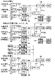
図1は、本発明のデータ多重化方法を応用した符号化装置の構成例を示している。この符号化装置は、N種類の複数再生経路を可能にするアプリケーションの生成を行うものである。ここで、Nは任意の自然数である。即ち、図2に示すように、多重化ストリームMbaとMBcの中間のN種類の多重化ストリームMBb(i)(i=1,2,...N)のうちのいずれか1種類が選択され、所定の再生経路が構成される。各多重化ストリームは、映像信号、音声信号、およびその他の信号(例えば字幕等)を符号化したエレメンタリーストリームから構成される。
【0057】
符号化装置を構成するビデオエンコーダ51は、入力された映像信号(VSa)を符号化し、エレメンタリーストリーム(VESa)を出力するようになされている。オーディオエンコーダ52は、入力された音響(音声)信号(ASa)を符号化し、エレメンタリーストリーム(AESa)を出力するようになされている。その他のエンコーダ53は、入力されたその他の信号ESaを符号化し、エレメンタリーストリーム(EESa)を出力するようになされている。
【0058】
アクセスユニット検出器54は、エレメンタリーストリーム(VESa)を入力し、そのアクセスユニットのサイズ、復号時刻、および表示時刻等の情報を検出するようになされている。アクセスユニット検出器55は、エレメンタリーストリーム(AESa)を入力し、そのアクセスユニットのサイズ、復号時刻、および表示(出力)時刻等の情報を検出するようになされている。アクセスユニット検出器56は、エレメンタリーストリーム(EESa)を入力し、そのアクセスユニットのサイズ、復号時刻、および表示(出力)時刻等の情報を検出するようになされている。
【0059】
スケジューラ57は、アクセスユニット54乃至56により検出された情報を入力し、それらの情報に基づいて、各パケットの長さ、パケットの順序、SCRの値等を決定するようになされている。これらの値は、パケット化情報PIaとしてパケット化器58に供給される。また、例えば、データ供給量の時間的な変化等のデータからなるデータ供給情報SIaを出力するようになされている。パケット化器58は、ビデオエンコーダ51、オーディオエンコーダ52、およびその他のエンコーダ53より供給されるエレメンタリーストリームを、スケジューラ57からのパケット化情報PIaに基づいてパケット化およびパック化を行い、多重化ストリームMBaを生成するようになされている。
【0060】
終端部占有量検出器59は、スケジューラ57からのデータ供給情報SIaに基づいて、各エレメンタリーストリームの終端部バッファ占有情報VBIa,ABIa,EBIaを求めるようになされている。
【0061】
ビデオエンコーダ61は、入力された映像信号(VSb(i))を符号化し、エレメンタリーストリーム(VESb(i))を出力するようになされている。オーディオエンコーダ62は、入力された音響(音声)信号(ASb(i))を符号化し、エレメンタリーストリーム(AESb(i))を出力するようになされている。その他のエンコーダ63は、入力されたその他の信号(ESb(i))を符号化し、エレメンタリーストリーム(EESb(i))を出力するようになされている。
【0062】
アクセスユニット検出器64は、エレメンタリーストリーム(VESb(i))を入力し、そのアクセスユニットのサイズ、復号時刻、および表示時刻等の情報を検出するようになされている。アクセスユニット検出器65は、エレメンタリーストリーム(AESb(i))を入力し、そのアクセスユニットのサイズ、復号時刻、および表示(出力)時刻等の情報を検出するようになされている。アクセスユニット検出器66は、エレメンタリーストリーム(EESb(i))を入力し、そのアクセスユニットのサイズ、復号時刻、および表示(出力)時刻等の情報を検出するようになされている。
【0063】
スケジューラ67は、アクセスユニット64乃至66により検出された情報を入力し、それらの情報に基づいて、各パケットの長さ、パケットの順序、SCRの値等を決定するようになされている。これらの値は、パケット化情報PIb(i)としてパケット化器68に出力される。また、多重化ストリームMBaの多重化において出力されたMBaの終端部バッファ占有情報に基づいて、多重化ストリームMBb(i)の先頭部の疑似バッファ容量を求め、これを初期値として多重化ストリームMBb(i)の多重化を行うようになされている。また、例えば、データ供給量の時間的な変化等のデータからなるデータ供給情報SIb(i)を出力するようになされている。
【0064】
パケット化器68は、ビデオエンコーダ61、オーディオエンコーダ62、およびその他のエンコーダ63より供給されるエレメンタリーストリームを、スケジューラ67からのパケット化情報PIb(i)に基づいてパケット化およびパック化を行い、多重化ストリームMBb(i)を生成するようになされている。
【0065】
終端部占有量検出器69は、スケジューラ67からのデータ供給情報SIb(i)に基づいて、各エレメンタリーストリームの終端部バッファ占有情報VBIb(i),ABIb(i),EBIb(i)を求めるようになされている。
【0066】
次に、多重化ストリームMBcの多重化を行う前に、最大占有量検出器71乃至73は、多重化ストリームMBb(i)の多重化において求められたN通りの終端部バッファ占有量VBIb(i),ABIb(i),EVBIb(i)(ただし、iは1,2,...N、Nは自然数)から、それぞれの最大占有量を検出し、各エレメンタリーストリームの終端部バッファ占有情報として、スケジューラ87に供給するようになされている。
【0067】
ビデオエンコーダ81は、入力された映像信号(VSc)を符号化し、エレメンタリーストリーム(VESc)を出力するようになされている。オーディオエンコーダ82は、入力された音響(音声)信号(ASc)を符号化し、エレメンタリーストリーム(AESc)を出力するようになされている。その他のエンコーダ83は、入力されたその他の信号EScを符号化し、エレメンタリーストリーム(EESc)を出力するようになされている。
【0068】
アクセスユニット検出器84は、エレメンタリーストリーム(VESc)を入力し、そのアクセスユニットのサイズ、復号時刻、および表示時刻等の情報を検出するようになされている。アクセスユニット検出器85は、エレメンタリーストリーム(AESc)を入力し、そのアクセスユニットのサイズ、復号時刻、および表示(出力)時刻等の情報を検出するようになされている。アクセスユニット検出器86は、エレメンタリーストリーム(EESc)を入力し、そのアクセスユニットのサイズ、復号時刻、および表示(出力)時刻等の情報を検出するようになされている。
【0069】
スケジューラ87は、最大占有量検出器71乃至73より供給される終端部占有情報に基づいて、多重化ストリームMBcの先頭部疑似バッファ容量を求め、この先頭部疑似バッファ容量と、アクセスユニット検出器84乃至86からの情報に基づいて、多重化ストリームMBcの多重化を行うようになされている。
【0070】
パケット化器88は、ビデオエンコーダ81、オーディオエンコーダ82、およびその他のエンコーダ83より供給されるエレメンタリーストリームを、スケジューラ87からのパケット化情報PIcに基づいてパケット化およびパック化を行い、多重化ストリームMBcを生成するようになされている。
【0071】
次に、その動作について説明する。最初に、多重化ストリームMBaが生成されるときの動作について説明する。映像信号VSaがビデオエンコーダ51に入力されると、符号化され、符号化されたデータであるエレメンタリーストリーム(VESa)が出力される。また、音声信号ASaがオーディオエンコーダ52に入力されると、符号化され、エレメンタリーストリーム(AESa)が出力される。また、その他の信号ESaがその他のエンコーダ53に入力されると、符号化され、エレメンタリーストリーム(EESa)が出力される。
【0072】
エレメンタリーストリーム(VESa)は、アクセスユニット検出器54に供給され、そこで、アクセスユニットのサイズ、復号時刻、および表示時刻等の情報が検出される。また、エレメンタリーストリーム(AESa)は、アクセスユニット検出器55に供給され、そこで、アクセスユニットのサイズ、復号時刻、および表示時刻等の情報が検出される。また、エレメンタリーストリーム(EESa)は、アクセスユニット検出器56に供給され、そこで、アクセスユニットのサイズ、復号時刻、および表示時刻等の情報が検出される。
【0073】
アクセスユニット検出器54乃至56において検出されたこれらの情報は、スケジューラ57に供給される。スケジューラ57により、これらの情報に基づいて、ビデオデータ、オーディオデータ等のパケットの長さやパックの長さ、パケットの順序、SCRの値等が決定される。この際、後述するように、アンダーフローを回避するために、終端部の多重化において、可能な限りすべてのバッファに対するデータの供給を早めておくようにする。スケジューラ57の詳細な動作については、図4および図6のフローチャートを参照して後述する。
【0074】
ビデオエンコーダ51、オーディオエンコーダ52、およびその他のエンコーダ53より出力された各エレメンタリーストリームVESa,AESa,EESaは、パケット化器58に入力され、スケジューラ57より供給されたパケット化情報PIaに基づいてパケット化およびパック化が行われ、多重化ストリームMBaが出力される。
【0075】
また、スケジューラ57により、エレメンタリーストリームVESa,AESa,EESaに基づいてデータ供給情報SIaが生成され、終端部占有量検出器59に供給される。このデータ供給情報SIaに基づいて、終端部占有量検出器59において、各エレメンタリーストリーム毎に終端部のバッファ占有状況を示す終端部バッファ占有情報VBIa,ABIa,EBIaが求められる。
【0076】
次に、多重化ストリームMBbが生成されるときの動作について説明する。多重化ストリームMBb(i)(i=1,2,...N)は、図2に示したように、N通り存在する。多重化ストリームMBb(i)のそれぞれの多重化の処理は、基本的には多重化ストリームMBaが生成される場合と同様であるので、その詳細な説明は省略するが、スケジューラ67は、多重化ストリームMBaが多重化されるとき出力された終端部バッファ占有情報に基づいて、多重化ストリームMBbの先頭部におけるバッファ容量である先頭部疑似バッファ容量を求め、これを初期値として多重化を行う。
【0077】
その際、多重化ストリームMBaの終端部時間から多重化の初期時刻を求め、これを多重化ストリームMBbの最初のパックのパックヘッダにおけるSCRとする。スケジューラ67の詳細な動作については、図7および図9のフローチャートを参照して後述する。
【0078】
多重化ストリームMBcの生成の前に、多重化ストリームMBbの多重化からN通りの終端部バッファ占有量VBIb(i),ABIb(i),EBIb(i)(i=1,2,...N)が求められるので、最大占有量検出器71乃至73において、各エレメンタリーストリームの最大占有量である終端部バッファ占有情報が求められる。
【0079】
最後に、多重化ストリームMBcが生成されるときの動作について説明する。この動作も、基本的には、多重化ストリームMBaが生成される場合と同様であるので、その詳細な説明は省略するが、スケジューラ87により、終端部バッファ占有情報に基づいて、各エレメンタリーストリーム毎にその対応するバッファの先頭部疑似バッファ容量が求められ、これをそれぞれのバッファの容量とみなして多重化が行われる。また、その際、多重化ストリームMBbの終端時間から、多重化の初期時刻が求められ、これを多重化ストリームMBcの最初のパックのパックヘッダにおけるSCRとされる。スケジューラ87の詳細な動作については、図11のフローチャートを参照して後述する。
【0080】
次に、バッファアンダーフローを回避する方法について説明する。図20を参照して上述したような、バッファアンダーフローを回避するためには、E−STDモデルにおけるすべてのバッファ(この場合、図18に示したバッファ25,26)において、多重化ストリームMBaの供給終了時刻TBa_endから、次に出力されるアクセスユニットの出力時刻TBa(n+1)までの時間が、多重化ストリームMBbの供給開始時刻TBb_startから最初のアクセスユニットの出力時刻TBb(1)までの時間より大きくなる必要がある。
【0081】
即ち、次式(1)に示すような関係が、E−STDモデルの全てのバッファ、あるいはエレメンタリーストリームに対して成り立つように、不連続点前後の多重化ストリームを生成する必要がある。
【0082】
TBa(n+1)−TBa_end>TBb(1)−TBb_start
・・・(式1)
【0083】
上記式(1)において、TBa(n+1)およびTBb(1)を固定値とすると、先行するMBaの供給終了時刻TBa_endが、時刻TBa(n+1)に対して値が小さい(時間的に早い)ほど、時刻TBb(1)に対して時刻TBb_startを決定する際の自由度が大きくなる。
【0084】
即ち、後続のMBbの多重化(データ供給の計画)における自由度を大きくすることが可能となる。よって、不連続点前後のそれぞれの多重化ストリームの多重化に関して、次のような条件を与えるようにする。
【0085】
(1)先行する多重化ストリームの終端部において、全てのバッファに対して可能な限り供給を早める多重化を行う。
(2)後続の多重化ストリームの多重化において、式(1)を満足するように、時刻TBb_startを決定する。
【0086】
次に、オーバーフローを回避する方法について説明する。複数経路再生における不連続点には、単一の多重化ストリームから複数の多重化ストリームに切り替える「分岐」と、複数の多重化ストリームから単一の多重化ストリームに切り替える「合流」の2種類が存在する。複数経路再生を行うあらゆるアプリケーションは、これらの組み合わせによって実現することが可能である。よって、以下では「分岐」と「合流」の場合に分けて、E−STDモデルにおけるバッファのオーバーフローを回避する多重化法について説明する。
【0087】
ここでは、図2に示すような複数経路再生における個々の多重化ストリームの多重化処理の手順を説明する。図2において、多重化ストリームMBaは、後続の複数の多重化ストリームMBb(i)(i=1,2,...N、Nは経路数)に切り替えられ、次に多重化ストリームMBcに切り替えられる。
【0088】
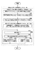
以下、図3のフローチャートを参照して、N個の経路再生が行われる場合の処理手順について説明する。最初、ステップS1において、多重化ストリームMBaの多重化処理が行われる。図4のフローチャートを参照して、その詳細について説明する。
【0089】
最初に、ステップS11において、データの供給を開始する時刻である供給開始時刻TBa_startとして、適当な値を選択する。次に、ステップS12において、選択された供給開始時刻TBa_startを多重化ストリームMBaの最初のパックのSCRとして設定する。次に、ステップS13において、多重化処理が終了したか否かが判定される。多重化処理が終了していないと判定された場合、ステップS14に進み、バッファ容量BS[k]をバッファkの容量として多重化する。ここで、変数kはバッファ数(K)を超えない任意の自然数とする。その後、ステップS13に戻り、ステップS13,S14の処理が繰り返される。
【0090】
一方、ステップS13において、多重化処理が終了したと判定された場合、処理を終了する。
【0091】
次に、図3のステップS2に進み、多重化ストリームMBaの後処理が行われ、ステップS3において、後続の多重化ストリームMBbの多重化処理が行われる。即ち、ここでは、「分岐」における多重化法に基づいた処理が行われる。上述したように、分岐とは、単一の先行する多重化ストリーム(この場合、MBa)から、複数の後続の多重化ストリーム(この場合、MBb(i)(i=1,2,...N))に切り替える場合のことである。以下に述べる多重化方法は、後続の全ての多重化ストリームに共通しているので、後続する多重化ストリームを適宜、単にMBbと表記する。
【0092】
図5(a)、図5(b)、および図5(c)は、E−STDモデル内の同一バッファにおける、多重化ストリームMBaとMBbのバッファ占有量の変化を表している。従って、ここでは、バッファを特定する変数kを適宜省略する。それぞれ、縦軸はバッファ占有量を表し、横軸は時間を表している。ここで、先行する多重化ストリームMBaは、タイムベースTBaに基づいてすでに生成されているものとする。即ち、図5(a)は、多重化ストリームMBaの供給における、タイムベースTBaに基づくバッファの占有量の変化を表している。同図において、時刻TBa_endは、多重化ストリームMBaのすべてのデータの供給が終了する供給終了時刻を表している。
【0093】
以下、図6のフローチャートを参照して、多重化ストリームMBaの後処理について説明する。最初に、ステップS21において、多重化ストリームMBaのデータ供給終了時刻TBa_endの検出および記録が行われる。次に、ステップS22において、最終アクセスユニットの復号終了時刻TBa[k](n+1)の検出が行われる。この復号終了時刻TBa[k](n+1)は、最終アクセスユニットの出力時刻に、その復号周期を加えたものである。
【0094】
次に、ステップS23に進み、終端部時間Da_end[k]の検出および記録が行われる。終端部時間Da_end[k]は、時刻TBa_endから、時刻TBa[k](n+1)までの時間、即ち、(TBa[k](n+1)−TBa_end)である。ステップS24においては、終端部バッファ占有情報BOa_end[k](ta)、即ち、時間Da_end[k]内の各時刻(ta)におけるバッファkの占有量の検出および記録が行われる。ただし、TBa_end≦ta≦TBa[k](n+1)とする。
【0095】
これらの処理は、多重化ストリームMBa内の全てのエレメンタリーストリームについて行われる。
【0096】
次に、図7のフローチャートを参照して、多重化ストリームMBaの後続の多重化ストリームMBbを多重化する手順について説明する。ここで、多重化ストリームMBbは、タイムベースTBbに基づいて生成されるものとする。
【0097】
任意のバッファkに対する処理として、最初、ステップS31において、最初のアクセスユニットの出力時刻TBb[k](1)の検出が行われる。次に、ステップS32に進み、多重化ストリームMBbの供給開始時刻TBb_startの算出が行われる。この時刻は、すべてのエレメンタリーストリームにおいて同値であり、時刻TBb[k](1)から時間Da_end[k]を差し引いた時刻とされる。
【0098】
ステップS33においては、供給開始時刻TBb_startを多重化ストリームMBb(i)の最初のパックのSCRとして設定する。ただし、この時刻TBb_startの値は、上記式(1)を満足する必要がある。ステップS31乃至S33の処理は、任意のエレメンタリーストリームに対して行われる。
【0099】
次に、個々のバッファkに対する処理として、時刻TBb_startから時間Da_end後までの間の各時刻において、バッファ容量BS[k]から、BOa_end[k](ta)分だけ差し引いたもの、即ち、先頭部疑似バッファ容量BSb_start[k](tb)の算出が行われる。ただし、TBb_start≦tb≦TBb_start+Da_end[k]、即ち、TBb_start≦tb≦TBb(1)とする。
【0100】
つまり、以下の関係が成り立つ。
【0101】
BSb_start[k](tb)=BS[k]−BOa_end[k](ta)
【0102】
ここで、時刻tbは、タイムベースTBbのサンプル値であり、
【0103】
ta=tb−TBb_start+TBa_end
【0104】
である。上述したように、BSb_start[k](tb)をそのエレメンタリーストリームの先頭部疑似バッファ容量と呼ぶことにする。
【0105】
次に、ステップS35において、多重化処理が終了したか否かが判定される。多重化処理が終了していないと判定された場合、ステップS36に進み、TBb_start≦tb≦TBb_start+Da_end[k]の関係を満たしているか否かが判定される。TBb_start≦tb≦TBb_start+Da_end[k]の関係を満たしていると判定された場合、ステップS37に進み、ステップS34において求められた各エレメンタリーストリームの先頭部疑似バッファ容量BSb_start[k](tb)を、時刻TBb_startから時刻TBb_start+Da_end[k]におけるバッファkの容量とみなして、それぞれのバッファが破綻しないように多重化する。
【0106】
図5(b)は、その一例を示したものである。ASa(n−2),ASa(n−1),ASa(n)は、時刻TBa(n−2),TBa(n−1),TBa(n)において出力されるアクセスユニットであり、矢印の長さはそのデータ量に対応している。多重化されるデータによるバッファ占有量が、先頭部疑似バッファ容量BSb_start(tb)を越えないように多重化ストリームMBbが多重化される。
【0107】
そして、ステップS35に戻り、ステップS35より以降の処理が繰り返し実行される。
【0108】
一方、TBb_start≦tb≦TBb_start+Da_end[k]の関係を満たしていないと判定された場合、ステップS38に進み、BS[k]をバッファkの容量とみなして多重化する。その後、ステップS35に戻り、ステップS35より以降の処理が繰り返し実行される。
【0109】
また、ステップS35において、多重化処理が終了したと判定された場合、多重化ストリームMBb(i)の多重化処理を終了する。
【0110】
図5(c)は、多重化ストリームMBaおよびMBbを連続再生した場合の同一バッファに関するものであり、タイムベースTBaに基づくバッファ占有量の変化を示している。上述したように、多重化ストリームMBbの多重化の際、多重化ストリームMBaの終端部におけるバッファ占有量が考慮されているため、全てのバッファにおいてオーバーフローは生じない。
【0111】
次に、図3のステップS4に進み、多重化ストリームMBb(i)の後処理が行われる。図8および図9を参照して、多重化ストリームMBb(i)の後処理について説明する。
【0112】
この処理は、上述した「合流」における多重化方法に基づくものであり、N本の先行する多重化ストリーム(この場合、多重化ストリームMBb(i)(i=1,2,...N))から、単一の後続の多重化ストリーム(この場合、多重化ストリームMBc)に切り替えるものである。
【0113】
ここでは、一般性を保つために、全ての先行する多重化ストリームの時間的な長さがそれぞれ異なるものとする。図8(a)乃至図8(c)は、複数経路再生の合流における先行する多重化ストリームの例を示している。ここでは、簡単のため、図2に示した、多重化ストリームMBbの数を3としている。それぞれ縦軸はバッファ容量を表し、横軸は時間を表している。
【0114】
最初に、図9のステップS41において、個々の多重化ストリームMBb(i)(ただし、1≦i≦N)に対する処理として、データ供給終了時刻TBb_end[i]の検出および記録が行われる。
【0115】
次に、ステップS42において、最終アクセスユニットの復号終了時刻TB[i][k](n+1)の検出が行われる。次に、ステップS43において、終端部時間Db_end[i][k]の検出が行われる。図10においては、それぞれDb_end(1)、Db_end(2)、Db_end(3)とされる。
【0116】
ステップS42およびS43の処理は、個々のバッファkに対して行われる。ただし、1≦k≦Kとする。
【0117】
次に、ステップS44において、終端部時間Db_end[i][k]のうち、最も短い最短終端時間Db_end_min[k]の検出が行われる。そして、ステップS45において、最短終端時間Db_end_min[k]を、それぞれ最終アクセスユニット復号終了時刻から差し引いた時刻が求められる。図10においては、それぞれTBb(1)(i+1)−Db_end(1)、TBb(2)(j+1)−Db_end(1)、TBb(3)(k+1)−Db_end(1)とされる。ただし、Db_end(1)<Db_end(3)<Db_end(2)である。そして、上記各時刻からそれぞれ最終アクセスユニットの復号終了時刻までのバッファkの占有量が各時刻について求められる。この処理は、個々のバッファkに対する処理として行われる。ただし、1≦k≦Kである。
【0118】
さらに、ステップS46において、最短終端時間Db_end_min[k]の各時刻におけるバッファ占有量の最大値の軌跡MaxBO_end[k]の検出および記録が行われる。図10(d)は、バッファ占有量の軌跡MaxBO_end[k]を示している。
【0119】
次に、図3のステップS5に進み、図11のフローチャートを参照して後述するように、図9のステップS43において求められた時間Db_end[i][k]を終端部時間とし、また、ステップS46において求められた軌跡MaxBO_end[k]を、終端部におけるバッファ占有量の最大値とみなして、図7のフローチャートを参照して上述した場合と基本的に同様の方法で、後続の多重化ストリームMBcの多重化が行われる。
【0120】
以下、図11を参照して、後続の多重化ストリームMBcを多重化する手順について説明する。
【0121】
任意のバッファkに対する処理として、最初、ステップS51において、最初のアクセスユニットの出力時刻TBc[k](1)の検出が行われる。次に、ステップS52に進み、多重化ストリームMBcの供給開始時刻TBc_startの算出が行われる。この時刻は、すべてのエレメンタリーストリームにおいて同値であり、時刻TBc[k](1)から、図9のステップS44において検出された最短終端時間Db_end_min[k]を差し引いた時刻とされる。
【0122】
ステップS53においては、供給開始時刻TBc_startを多重化ストリームMBcの最初のパックのSCRとして設定する。ステップS51乃至S53の処理は、任意のエレメンタリーストリームに対して行われる。
【0123】
次に、個々のバッファkに対する処理として、時刻TBc_startから時間Db_end_min(k)後までの間の各時刻において、バッファ容量BS[k]から、図9のステップS46において求められたMaxBO_end(tc)分だけ差し引いたもの、即ち、先頭部疑似バッファ容量BSc_start[k](tc)の算出が行われる。ただし、TBc_start≦tc≦TBc_start+Db_end_min[k]とする。
【0124】
次に、ステップS55において、多重化処理が終了したか否かが判定される。多重化処理が終了していないと判定された場合、ステップS56に進み、TBc_start≦tc≦TBc_start+Db_end_min[k]の関係を満たしているか否かが判定される。TBc_start≦tc≦TBc_start+Db_end_min[k]の関係を満たしていると判定された場合、ステップS57に進み、ステップS54において求められた各エレメンタリーストリームの先頭部疑似バッファ容量BSc_start[k](tc)を、時刻TBc_startから時刻TBc_start+Db_end_min[k]におけるバッファkの容量とみなして、それぞれのバッファが破綻しないように多重化する。
【0125】
そして、ステップS55に戻り、ステップS55より以降の処理が繰り返し実行される。
【0126】
一方、TBc_start≦tc≦TBc_start+Db_end_min[k]の関係を満たしていないと判定された場合、ステップS58に進み、BS[k]をバッファkの容量とみなして多重化する。その後、ステップS55に戻り、ステップS55より以降の処理が繰り返し実行される。
【0127】
また、ステップS55において、多重化処理が終了したと判定された場合、多重化ストリームMBcの多重化処理を終了する。
【0128】
このようにして多重化された複数の多重化ストリームは、例えば、記録可能なDVD(Digiatl Versatile Disc)等の記録媒体4の各部に記録されるようにしてもよいし、これらの複数の多重化ストリームをさらに1本のトランスポートストリームにまとめて伝送路5を介して伝送するようにすることも可能である。
【0129】
なお、上記実施例においては、本発明を主に記録用途のMPEG1システムストリーム、およびMPEG2プログラムストリームに応用する場合について説明したが、主に伝送用途に使用されるMPEG2トランスポートストリームに応用することも可能である。
【0130】
トランスポートストリームにおいては、1本のストリームが複数のチャンネルで構成され、各チャンネルが単一の独立したストリームに相当する。また、各チャンネルは、それぞれ独立したタイムベースに基づいて生成される。従って、上記複数のプログラムストリームに対する方法を、そのまま各チャンネルに対して行い、1本のトランスポートストリームを構成することにより、複数のチャンネルを切り替えるときに、各チャンネルを復号装置におけるバッファが破綻しないように多重化させることが可能である。
【0131】
また、上記実施例においては、記録媒体として記録可能なディジタルバーサタイルディスク(DVD:Digital Versatile Disc)を用いるようにしたが、光ディスク(Optical Disc)、ミニディスク(MD:Mini Disc(商標))、光磁気ディスク(Magneto−Optic Disc)、磁気テープ等のその他の記録媒体を用いるようにすることも可能である。
【0132】
また、上記実施例は、映像信号および音声信号等を伝送路を介して送信側から送信し、それを受信側において受信し、対応する映像や音声を表示、または出力する、例えば、テレビ会議システム、テレビ電話システム、放送用機器等に用いることができる。
【0134】
【発明の効果】
請求項1に記載のデータ多重化方法によれば、多重化ストリームの所定のものに先行する多重化ストリームの他の所定のものの終端部において、復号装置の有する多重化ストリームを記憶するバッファメモリの占有量を検出し、占有量に基づいて、多重化ストリームの所定のものを記憶可能なバッファメモリの容量を仮想的に設定し、仮想的に設定したバッファメモリの容量を越えない範囲内で、各バッファメモリに多重化ストリームの所定のものが供給されるように制御するようにしたので、複数の多重化ストリームを切り替えて再生する場合におけるバッファメモリの破綻を抑制することができる。
【0135】
請求項2に記載のデータ多重化方法によれば、多重化ストリームの所定のものに先行する多重化ストリームの他の所定のものを構成するエレメンタリーストリームの、復号装置の有するバッファメモリへの供給が終了する終了時刻と、多重化ストリームの他の所定のものを構成する全てのエレメンタリーストリームの最終アクセスユニットがバッファメモリから出力される第1の出力時刻と、アクセスユニットの復号周期と、多重化ストリームの所定のものを構成する全てのエレメンタリーストリームの最初のアクセスユニットがバッファメモリから出力される第2の出力時刻とを検出し、検出した終了時刻、第1の出力時刻、復号周期、および第2の出力時刻に基づいて、多重化ストリームの所定のものの多重化の初期時刻を決定するようにしたので、複数の多重化ストリームを切り替えて再生する場合におけるバッファメモリの破綻を抑制することができる。
【図面の簡単な説明】
【図1】本発明を適用した符号化装置の構成例を示すブロック図である。
【図2】複数経路再生の例を示す図である。
【図3】図2に示した複数経路再生における多重化ストリームの多重化処理を説明するためのフローチャートである。
【図4】多重化ストリームMBaの多重化処理を説明するためのフローチャートである。
【図5】複数経路再生の分岐における多重化を説明するための図である。
【図6】多重化ストリームMBaの後処理を説明するためのフローチャートである。
【図7】多重化ストリームMBb(i)の多重化処理を説明するためのフローチャートである。
【図8】複数経路再生の合流における先行多重化ストリームの例を示す図である。
【図9】多重化ストリームMBb(i)の後処理を説明するためのフローチャートである。
【図10】複数経路再生の合流における先行多重化ストリームの処理例を示す図である。
【図11】多重化ストリームMBcの多重化処理を説明するためのフローチャートである。
【図12】従来の送受信システムの構成例を示すブロック図である。
【図13】ISO/IEC13818−1プログラムストリーム、あるいはISO/IEC11172−1システムストリームの構造を示す図である。
【図14】ISO/IEC13818−1プログラムストリーム、あるいはISO/IEC11172−1システムストリームのSTDモデルを示す図である。
【図15】複数経路再生の概念を示す図である。
【図16】選択された再生経路番号に基づく各多重化ストリームの入力制御を説明するための図である。
【図17】復号化装置に入力される複数の多重化ストリーム列の例を示す図である。
【図18】本発明を適用したデコーダの構成例を示す図である。
【図19】多重化ストリームの不連続点におけるE−STDモデルのバッファの破綻例(オーバーフロー)を示す図である。
【図20】多重化ストリームの不連続点におけるE−STDモデルのバッファの破綻例(アンダーフロー)を示す図である。
【符号の説明】
1 ビデオエンコーダ,2 オーディオエンコーダ,3 多重化器,4 記録媒体,5 伝送路,6 分離器,7 ビデオデコーダ,8 オーディオデコーダ,11 STC,12 分離器,13,14 バッファ,15 ビデオデコーダ,16 オーディオデコーダ,17 再配列バッファ,51,61,81 ビデオエンコーダ,52,62,82 オーディオエンコーダ,53,63,83 その他のエンコーダ,54乃至56,64乃至66,84乃至86 アクセスユニット検出器,57,67,87 スケジューラ,58,68,88 パケット化器,59,69 終端部占有量検出器,71乃至73 最大占有量検出器[0001]
The present invention relates to a data multiplexing method. For example, when a plurality of multiplexed streams including a plurality of video signals and audio signals are input to a decoding device and switched to be reproduced, the buffer memory of the decoding device does not fail. And a data multiplexing method.
[0002]
[Prior art]
FIG. 12 shows a configuration example of a transmission / reception system for transmitting / receiving signals such as video and audio. On the transmission side (encoding device), a video encoder (encoder) 1 encodes an input video signal. The
[0003]
The signal multiplexed by the
[0004]
On the receiving side (decoding device), the separator 6 separates the coded and multiplexed data supplied via the
[0005]
For example, on the transmission side, input signals such as video and audio are encoded by the
[0006]
On the receiving side, the encoded and multiplexed video data and audio data recorded on the
[0007]
The MPEG (Moving Picture Experts Group) system (ISO / IEC 13818-1 and ISO / IEC 11172-1) is an international standard for a system for multiplexing and demultiplexing encoded data such as video and audio as described above. Hereinafter, encoded data such as video and audio will be referred to as an elementary stream. In particular, coded data of a video signal is called a video stream, and coded data of an audio signal is called an audio stream. Further, data obtained by multiplexing the plurality of elementary streams is referred to as a multiplexed stream.
[0008]
In the following, for the sake of simplicity, only the MPEG1 (ISO / IEC 117182-1) system stream and the MPEG2 (ISO / IEC 13818-1) program stream will be described as multiplexed streams, but the present invention is applied to the MPEG2 transport stream. Is also possible.
[0009]
FIG. 13 is a diagram showing the structure of a multiplexed stream defined in the MPEG system. As shown in the figure, the multiplexed stream is composed of a plurality of packs. A pack header is added to each pack, and information such as an SCR (System Clock Reference) and a multiplexing rate (Mux_rate) described later is described in the pack header. Each pack is composed of a plurality of packets, and elementary streams such as video and audio are divided and inserted into each pack. A packet header is added to each packet, in which a time stamp described later is described.
[0010]
FIG. 14 shows a configuration example of a decoding apparatus to which a multiplexed stream separation method defined in the MPEG system is applied. This separation method uses a virtual decoder, and is called an STD (System Target Decoder) model. Hereinafter, the operation will be described.
[0011]
The STD model has a reference clock STC (System Time Clock) 11 therein, and the
[0012]
The input of the multiplexed stream to the STD model is controlled by STC and SCR. That is, as soon as the value of the read SCR becomes equal to the value of the STC, the input of the pack whose SCR is described in the pack header is started. The input speed at that time is called a multiplexing rate and is described in each pack header.
[0013]
In the
[0014]
The data supplied to the
[0015]
The time stamp includes DTS (Decoding Time-Stamp) and PTS (Presentation Time-Stamp). The DTS indicates a time at which an access unit is output from the
[0016]
Generally, when the values of DTS and PTS are equal in a predetermined elementary stream, only PTS is described in the packet header. For example, MPEG audio (ISO / IEC 13818-3 and ISO / IEC 11172-3) corresponds to this. In addition, MPEG video (ISO / IEC 13818-2 and ISO / IEC 111722-2) has a decoding delay depending on the type of access unit. In this case, both the DTS and PTS time stamps are described. . The
[0017]
The SCR value is a sample value of a reference clock (time base) in an encoding device (including a multiplexer), and is used by using each sample buffer (in this case, buffers 13 and 14) of a decoding device (STD model). ) Is possible. That is, in all buffers, the STD does not overflow (data supplied to the buffer exceeds the buffer capacity) and underflow (access units do not all reach the buffer at the time to be decoded). It is required that the value of the SCR be set appropriately in the encoder to be decoded in the model.
[0018]
An application example using a plurality of multiplexed streams described above is, for example, "multiple path reproduction". The multi-path reproduction includes, for example, “Language Credit (language-dependent video reproduction)”, “Director's Cut (cut directed by a movie director: Parental Lock, etc.)”, or “Multi-angles (shooting with multiple cameras) This is a function of performing a plurality of path reproductions by a user's selection in a single application.
[0019]
FIG. 15 shows an example of multi-path reproduction. In this example, there are three types of reproduction paths, and the arrows in the figure indicate a case in which one type (reproduction path 3) is selected for reproduction. Each playback path is composed of a plurality of multiplexed streams generated based on independent time bases. The multiplexed streams MBa and MBc are common to all reproduction paths, and three multiplexed streams MBb (1) to MBb (3) can be selected in the middle of the streams. For example, the
[0020]
Each multiplexed stream in the multi-path reproduction shown in FIG. 15 is recorded and transmitted in an arrangement and an order as shown in FIG. 16, for example. At this time, the decoding device controls the input for each multiplexed stream based on the selected reproduction path. FIG. 16 shows an example of the reproduction order when the
[0021]
When the input is controlled in this way, the arrangement of the data actually input to the decoding device is multiplexed streams MBa, MBb (2), MBc as shown in FIG. Hereinafter, a connection point between the multiplexed stream and the multiplexed stream will be referred to as a “discontinuity point” of the multiplexed stream.
[0022]
In the above-mentioned STD model, continuous input of a multiplexed stream generated based on an independent time base is not assumed, so that reproduction is performed in the vicinity of the discontinuity point so that there is no buffer failure. Impossible. Therefore, as shown in FIG. 18, it is conceivable to use an E-STD model obtained by expanding the STD model.
[0023]
The E-STD model shown in FIG. 18 enables input of a pack, decoding of each elementary stream, and switching of a reference clock referred to in output control near a discontinuous point of a multiplexed stream that is continuously input. The
[0024]
However, when each of the multiplexed streams (MBa and MBb) before and after the discontinuity point is reproduced independently, all the switches (switches 23, 27, 28, 31) are connected to the a side, and the operation is performed by the STD. The model shall be followed.
[0025]
When the
[0026]
For example, a value obtained by adding the display (output) cycle to the decoding time of the last access unit of the preceding video stream MBa and the display (output) time of the first access unit of the subsequent video stream MBb are set to the value of the variable α. The value of the variable α is set so that the times at which.
[0027]
The
[0028]
The
[0029]
The
[0030]
The
[0031]
At the moment when all the
[0032]
[Problems to be solved by the invention]
In the E-STD model, the buffer (decoding buffer) 25 or the buffer (decoding buffer) 26 in the E-STD model may fail at a discontinuous point of the multiplexed stream. Hereinafter, an example in which the
[0033]
Hereinafter, for example, TBa (i) is a time based on the time base TBa, and indicates a time at which the i-th access unit is output from the target buffer. Further, the data supply end time for all the buffers (in this case, buffers 25 and 26) when the multiplexed stream MBa is reproduced alone is set to a time TBa_end based on the time base TBa. Further, the data supply start time in the single reproduction of the multiplexed stream MBb is set to a time TBb_start based on the time base TBb.
[0034]
FIGS. 19A to 19C show an example of an overflow in the buffer (in this case, the
[0035]
However, FIG. 19A shows only the end portion of the multiplexed stream MBa, and FIG. 19B shows only the head portion of the multiplexed stream MBb. As shown in the figure, it is assumed that the multiplexed streams are multiplexed so that the data is supplied without a failure of the buffer in the single reproduction.
[0036]
FIG. 19C shows a change in the occupancy of the buffer based on the time base TBa when the multiplexed streams MBa and MBb are continuously reproduced. As shown in the figure, at the moment when the supply of the multiplexed stream MBa is completed (time TBa_end), the supply of the multiplexed stream MBb is started, and thereafter, at time TBa_overflow based on the time base TBa, a buffer overflow may occur. There was an issue.
[0037]
This is because the supply of the multiplexed stream MBb is planned independently of the supply of the multiplexed stream MBa. That is, in the multiplexing of the MBb, the buffer occupancy due to the supply of the preceding multiplexed stream MBa, particularly, the buffer occupancy at the end portion is not considered at all.
[0038]
Next, an example of an underflow in a buffer (in this case, buffer 25 or 26) in the E-STD model is shown with reference to FIG. The vertical axis represents the buffer occupancy, and the horizontal axis represents time. FIGS. 20 (a) and 20 (b) relate to the same buffer in the E-STD model, as in FIGS. 19 (a) and 19 (b). It shows changes in the buffer occupancy based on the respective time bases TBa and TBb in MBb single reproduction.
[0039]
However, FIG. 20A shows only the end of the multiplexed stream MBa, and FIG. 20B shows only the head of the multiplexed stream MBb. As shown in the figure, it is assumed that the multiplexed streams MBa and MBb are multiplexed so that the data is supplied without failure of the buffer when the single reproduction is performed.
[0040]
FIG. 20C shows a change in the occupancy of the buffer based on the time base TBa when the multiplexed streams MBa and MBb are continuously reproduced. As shown in the drawing, at the moment when the supply of the multiplexed stream MBa is completed (time TBa_end), the supply of the multiplexed stream MBb is started.
[0041]
However, when the next access unit (ASb (1): the first access unit in the multiplexed stream MBb) is output at time TBa (n + 1), all of the access units (ASb (1)) are still in the buffer. , The buffer underflow may occur at the same time.
[0042]
This is because the supply start time of the multiplexed stream MBb was too late and the supply start time of the multiplexed stream MBb was also delayed, so that the supply of the first access unit ASb (1) of the multiplexed stream MBb could not be made in time. It depends. However, the time TBa (n + 1) is obtained by adding the decoding time to the output time TBa (n) from the buffer of the last access unit of the multiplexed stream MBa.
[0043]
The present invention has been made in view of such a situation, and it is an object of the present invention to prevent a decoding buffer from failing at a discontinuous point of a multiplexed stream in multi-path reproduction.
[0045]
[Means for Solving the Problems]
Claim1The data multiplexing method described in (1) detects the occupancy of a buffer memory that stores the multiplexed stream of the decoding device at the end of another predetermined multiplexed stream preceding the predetermined one of the multiplexed streams. Based on the occupancy, the capacity of a buffer memory capable of storing a predetermined multiplexed stream is virtually set, and multiplexing is performed on each buffer memory within a range not exceeding the virtually set buffer memory capacity. It is characterized in that control is performed so that a predetermined stream of the conversion stream is supplied.
[0046]
Claim2The data multiplexing method according to the above, wherein the end time at which the supply of the elementary stream constituting another predetermined multiplexed stream preceding the predetermined multiplexed stream to the buffer memory of the decoding device ends. A first output time at which the last access units of all the elementary streams constituting another predetermined multiplex stream are output from the buffer memory, a decoding cycle of the access units, and a predetermined time of the multiplex stream. The first access unit of all elementary streams constituting the object detects the second output time output from the buffer memory, and detects the detected end time, first output time, decoding cycle, and second output. An initial time for multiplexing a predetermined multiplex stream is determined based on the time.
[0051]
Claim1In the data multiplexing method described in the above, the occupation amount of the buffer memory storing the multiplexed stream of the decoding device is detected at the end of another predetermined multiplexed stream preceding the predetermined multiplexed stream. Then, based on the occupancy, the capacity of a buffer memory capable of storing a predetermined multiplexed stream is virtually set, and each buffer memory is set within a range not exceeding the capacity of the virtually set buffer memory. Control is performed so that a predetermined multiplexed stream is supplied.
[0052]
Claim2In the data multiplexing method according to the item (1), the supply of the elementary streams constituting another predetermined one of the multiplexed streams preceding the predetermined one of the multiplexed streams to the buffer memory of the decoding device is terminated. A time, a first output time at which the last access units of all the elementary streams constituting another predetermined one of the multiplexed streams are output from the buffer memory, a decoding cycle of the access units, and a predetermined time of the multiplexed stream. The first access unit of all the elementary streams that constitute the elementary stream detects the second output time output from the buffer memory, and detects the detected end time, first output time, decoding cycle, and second output time. Based on the output time, an initial time for multiplexing a predetermined one of the multiplexed streams is determined.
[0056]
BEST MODE FOR CARRYING OUT THE INVENTION
FIG. 1 shows a configuration example of an encoding device to which the data multiplexing method of the present invention is applied. This encoding apparatus generates an application that enables N types of multiple reproduction paths. Here, N is an arbitrary natural number. That is, as shown in FIG. 2, any one of N types of multiplexed streams MBb (i) (i = 1, 2,... N) intermediate between the multiplexed streams Mba and MBc is selected. , A predetermined reproduction path is configured. Each multiplexed stream is composed of an elementary stream obtained by encoding a video signal, an audio signal, and other signals (for example, subtitles).
[0057]
The
[0058]
The access unit detector 54 receives an elementary stream (VESa) and detects information such as the size, decoding time, and display time of the access unit. The access unit detector 55 receives the elementary stream (AESa) and detects information such as the size, decoding time, and display (output) time of the access unit. The
[0059]
The
[0060]
The
[0061]
The
[0062]
The access unit detector 64 receives the elementary stream (VESb (i)) and detects information such as the size, decoding time, and display time of the access unit. The access unit detector 65 receives the elementary stream (AESb (i)) and detects information such as the size, decoding time, and display (output) time of the access unit. The access unit detector 66 receives the elementary stream (EESb (i)) and detects information such as the size, decoding time, and display (output) time of the access unit.
[0063]
The
[0064]
The
[0065]
The end part occupancy detector 69 obtains end part buffer occupancy information VBIb (i), ABIb (i), and EBIb (i) of each elementary stream based on the data supply information SIb (i) from the
[0066]
Next, before multiplexing the multiplexed stream MBc, the
[0067]
The
[0068]
The
[0069]
The
[0070]
The
[0071]
Next, the operation will be described. First, an operation when the multiplexed stream MBa is generated will be described. When the video signal VSa is input to the
[0072]
The elementary stream (VESa) is supplied to an access unit detector 54, where information such as the size of the access unit, decoding time, and display time is detected. The elementary stream (AESa) is supplied to the access unit detector 55, where information such as the size of the access unit, decoding time, and display time is detected. The elementary stream (EESa) is supplied to the
[0073]
These pieces of information detected by the access unit detectors 54 to 56 are supplied to a
[0074]
Each of the elementary streams VESa, AESa, and EESa output from the
[0075]
Further, the
[0076]
Next, an operation when the multiplexed stream MBb is generated will be described. As shown in FIG. 2, there are N multiplexed streams MBb (i) (i = 1, 2,... N). The multiplexing process of each of the multiplexed streams MBb (i) is basically the same as the case where the multiplexed stream MBa is generated, and thus detailed description thereof is omitted. Based on the ending buffer occupancy information output when the stream MBa is multiplexed, a head pseudo buffer capacity which is a buffer capacity at the head of the multiplexed stream MBb is obtained, and multiplexing is performed using this as an initial value.
[0077]
At this time, an initial time of multiplexing is obtained from the end time of the multiplexed stream MBa, and this is set as the SCR in the pack header of the first pack of the multiplexed stream MBb. The detailed operation of the
[0078]
Prior to the generation of the multiplexed stream MBc, N ending buffer occupancies VBIb (i), ABIb (i), EBIb (i) (i = 1, 2,. N) is obtained, so that the
[0079]
Finally, an operation when the multiplexed stream MBc is generated will be described. This operation is also basically the same as the case where the multiplexed stream MBa is generated, and a detailed description thereof will be omitted. However, the
[0080]
Next, a method for avoiding buffer underflow will be described. In order to avoid buffer underflow as described above with reference to FIG. 20, in all buffers in the E-STD model (in this case, buffers 25 and 26 shown in FIG. 18), the multiplexed stream MBa The time from the supply end time TBa_end to the output time TBa (n + 1) of the access unit to be output next is longer than the time from the supply start time TBb_start of the multiplexed stream MBb to the output time TBb (1) of the first access unit. Need to grow.
[0081]
That is, it is necessary to generate a multiplexed stream before and after a discontinuity point so that the relationship represented by the following equation (1) holds for all buffers or elementary streams of the E-STD model.
[0082]
TBa (n + 1) -TBa_end> TBb (1) -TBb_start
... (Equation 1)
[0083]
In the above equation (1), assuming that TBa (n + 1) and TBb (1) are fixed values, the preceding MBa supply end time TBa_end has a smaller value (time earlier) than the time TBa (n + 1). , The degree of freedom in determining the time TBb_start with respect to the time TBb (1) is increased.
[0084]
That is, it is possible to increase the degree of freedom in the subsequent MBb multiplexing (data supply planning). Therefore, the following conditions are applied to the multiplexing of each multiplexed stream before and after the discontinuity point.
[0085]
(1) At the end of the preceding multiplexed stream, multiplexing is performed to supply all buffers as quickly as possible.
(2) In the subsequent multiplexing of the multiplexed stream, the time TBb_start is determined so as to satisfy Expression (1).
[0086]
Next, a method for avoiding overflow will be described. There are two types of discontinuous points in the multi-path reproduction, "branch" for switching from a single multiplexed stream to a plurality of multiplexed streams, and "merging" for switching from a plurality of multiplexed streams to a single multiplexed stream. Exists. Any application that performs multi-path playback can be realized by a combination of these. Therefore, a multiplexing method for avoiding a buffer overflow in the E-STD model will be described below separately for the case of “branch” and the case of “merging”.
[0087]
Here, the procedure of the multiplexing process of the individual multiplexed streams in the multi-path reproduction as shown in FIG. 2 will be described. 2, the multiplexed stream MBa is switched to a plurality of subsequent multiplexed streams MBb (i) (i = 1, 2,... N, N is the number of paths), and then switched to a multiplexed stream MBc. Can be
[0088]
Hereinafter, a processing procedure in the case where N pieces of path reproduction are performed will be described with reference to the flowchart of FIG. First, in step S1, a multiplexing process of the multiplexed stream MBa is performed. The details will be described with reference to the flowchart of FIG.
[0089]
First, in step S11, an appropriate value is selected as a supply start time TBa_start, which is a time at which data supply starts. Next, in step S12, the selected supply start time TBa_start is set as the SCR of the first pack of the multiplexed stream MBa. Next, in step S13, it is determined whether the multiplexing process has been completed. If it is determined that the multiplexing process has not been completed, the process proceeds to step S14, where the buffer capacity BS [k] is multiplexed as the capacity of the buffer k. Here, the variable k is an arbitrary natural number that does not exceed the number of buffers (K). Thereafter, the process returns to step S13, and the processes of steps S13 and S14 are repeated.
[0090]
On the other hand, if it is determined in step S13 that the multiplexing process has ended, the process ends.
[0091]
Next, the process proceeds to step S2 in FIG. 3, where post-processing of the multiplexed stream MBa is performed, and in step S3, multiplexing processing of the subsequent multiplexed stream MBb is performed. That is, here, processing based on the multiplexing method in “branch” is performed. As described above, a branch is defined as a single preceding multiplexed stream (in this case, MBa) from a plurality of subsequent multiplexed streams (in this case, MBb (i) (i = 1, 2,...). N)). Since the multiplexing method described below is common to all subsequent multiplexed streams, the subsequent multiplexed stream is simply referred to as MBb as appropriate.
[0092]
FIGS. 5A, 5B, and 5C show changes in the buffer occupancy of the multiplexed streams MBa and MBb in the same buffer in the E-STD model. Therefore, here, the variable k specifying the buffer is appropriately omitted. The vertical axis represents the buffer occupancy, and the horizontal axis represents time. Here, it is assumed that the preceding multiplexed stream MBa has already been generated based on the time base TBa. That is, FIG. 5A illustrates a change in the occupation amount of the buffer based on the time base TBa in the supply of the multiplexed stream MBa. In the figure, a time TBa_end indicates a supply end time at which supply of all data of the multiplexed stream MBa ends.
[0093]
Hereinafter, the post-processing of the multiplexed stream MBa will be described with reference to the flowchart of FIG. First, in step S21, detection and recording of the data supply end time TBa_end of the multiplexed stream MBa are performed. Next, in step S22, the decoding end time TBa [k] (n + 1) of the last access unit is detected. The decoding end time TBa [k] (n + 1) is obtained by adding the decoding cycle to the output time of the last access unit.
[0094]
Next, the process proceeds to step S23, where the end part time Da_end [k] is detected and recorded. The end part time Da_end [k] is a time from the time TBa_end to the time TBa [k] (n + 1), that is, (TBa [k] (n + 1) -TBa_end). In step S24, the terminal buffer occupancy information BOa_end [k] (ta), that is, the occupation amount of the buffer k at each time (ta) within the time Da_end [k] is detected and recorded. However, it is assumed that TBa_end ≦ ta ≦ TBa [k] (n + 1).
[0095]
These processes are performed on all the elementary streams in the multiplexed stream MBa.
[0096]
Next, a procedure for multiplexing a multiplexed stream MBb subsequent to the multiplexed stream MBa will be described with reference to the flowchart in FIG. Here, it is assumed that the multiplexed stream MBb is generated based on the time base TBb.
[0097]
As processing for an arbitrary buffer k, first, in step S31, the output time TBb [k] (1) of the first access unit is detected. Next, the process proceeds to step S32, where the supply start time TBb_start of the multiplexed stream MBb is calculated. This time has the same value in all elementary streams, and is the time obtained by subtracting the time Da_end [k] from the time TBb [k] (1).
[0098]
In step S33, the supply start time TBb_start is set as the SCR of the first pack of the multiplexed stream MBb (i). However, the value of the time TBb_start needs to satisfy the above equation (1). The processing of steps S31 to S33 is performed on an arbitrary elementary stream.
[0099]
Next, as processing for each buffer k, at each time from the time TBb_start to the time after the time Da_end, a value obtained by subtracting BOa_end [k] (ta) from the buffer capacity BS [k], that is, the head part The calculation of the pseudo buffer capacity BSb_start [k] (tb) is performed. However, TBb_start ≦ tb ≦ TBb_start + Da_end [k], that is, TBb_start ≦ tb ≦ TBb (1).
[0100]
That is, the following relationship is established.
[0101]
BSb_start [k] (tb) = BS [k] -BOa_end [k] (ta)
[0102]
Here, the time tb is a sample value of the time base TBb,
[0103]
ta = tb−TBb_start + TBa_end
[0104]
It is. As described above, BSb_start [k] (tb) is referred to as the head pseudo buffer capacity of the elementary stream.
[0105]
Next, in step S35, it is determined whether the multiplexing process has been completed. If it is determined that the multiplexing process has not been completed, the process proceeds to step S36, and it is determined whether the relationship of TBb_start ≦ tb ≦ TBb_start + Da_end [k] is satisfied. If it is determined that the relationship of TBb_start ≦ tb ≦ TBb_start + Da_end [k] is satisfied, the process proceeds to step S37, and the head pseudo buffer capacity BSb_start [k] (tb) of each elementary stream obtained in step S34 is calculated as Assuming the capacity of the buffer k from the time TBb_start to the time TBb_start + Da_end [k], multiplexing is performed so that each buffer does not fail.
[0106]
FIG. 5B shows an example. ASa (n-2), ASa (n-1), and ASa (n) are access units output at times TBa (n-2), TBa (n-1), and TBa (n). The length corresponds to the amount of data. The multiplexed stream MBb is multiplexed so that the buffer occupancy by the multiplexed data does not exceed the head pseudo buffer capacity BSb_start (tb).
[0107]
Then, the process returns to step S35, and the processes after step S35 are repeatedly executed.
[0108]
On the other hand, when it is determined that the relationship of TBb_start ≦ tb ≦ TBb_start + Da_end [k] is not satisfied, the process proceeds to step S38, where BS [k] is regarded as the capacity of the buffer k and multiplexed. After that, the process returns to step S35, and the processes after step S35 are repeatedly executed.
[0109]
If it is determined in step S35 that the multiplexing process has been completed, the multiplexing process of the multiplexed stream MBb (i) is completed.
[0110]
FIG. 5C relates to the same buffer when the multiplexed streams MBa and MBb are continuously played back, and shows a change in the buffer occupancy based on the time base TBa. As described above, at the time of multiplexing the multiplexed stream MBb, the buffer occupancy at the end of the multiplexed stream MBa is taken into consideration, so that no overflow occurs in all buffers.
[0111]
Next, the process proceeds to step S4 in FIG. 3, where post-processing of the multiplexed stream MBb (i) is performed. The post-processing of the multiplexed stream MBb (i) will be described with reference to FIGS.
[0112]
This processing is based on the multiplexing method in the “merging” described above, and includes N preceding multiplexed streams (in this case, multiplexed streams MBb (i) (i = 1, 2,... N)). ) To a single subsequent multiplexed stream (in this case, multiplexed stream MBc).
[0113]
Here, in order to maintain generality, it is assumed that all preceding multiplexed streams have different temporal lengths. FIGS. 8A to 8C show examples of preceding multiplexed streams in the merge of the multi-path reproduction. Here, for simplicity, the number of multiplexed streams MBb shown in FIG. 2 is three. The vertical axis represents buffer capacity, and the horizontal axis represents time.
[0114]
First, in step S41 of FIG. 9, detection and recording of the data supply end time TBb_end [i] are performed as processing for each multiplexed stream MBb (i) (where 1 ≦ i ≦ N).
[0115]
Next, in step S42, the decoding end time TB [i] [k] (n + 1) of the last access unit is detected. Next, in step S43, the end part time Db_end [i] [k] is detected. In FIG. 10, they are Db_end (1), Db_end (2), and Db_end (3), respectively.
[0116]
The processing of steps S42 and S43 is performed for each buffer k. However, it is assumed that 1 ≦ k ≦ K.
[0117]
Next, in step S44, the shortest shortest terminal time Db_end_min [k] among the terminal part times Db_end [i] [k] is detected. Then, in step S45, a time is obtained by subtracting the shortest end time Db_end_min [k] from the last access unit decoding end time. In FIG. 10, TBb (1) (i + 1) -Db_end (1), TBb (2) (j + 1) -Db_end (1), and TBb (3) (k + 1) -Db_end (1), respectively. However, Db_end (1) <Db_end (3) <Db_end (2). Then, the occupation amount of the buffer k from each time to the decoding end time of the last access unit is obtained for each time. This process is performed as a process for each buffer k. However, 1 ≦ k ≦ K.
[0118]
Further, in step S46, the locus MaxBO_end [k] of the maximum value of the buffer occupancy at each time of the shortest end time Db_end_min [k] is detected and recorded. FIG. 10D shows the locus MaxBO_end [k] of the buffer occupancy.
[0119]
Next, the process proceeds to step S5 in FIG. 3, and as described later with reference to the flowchart in FIG. 11, the time Db_end [i] [k] obtained in step S43 in FIG. The trajectory MaxBO_end [k] obtained in S46 is regarded as the maximum value of the buffer occupancy at the terminal end, and the subsequent multiplexed stream is processed in basically the same manner as described above with reference to the flowchart of FIG. Multiplexing of MBc is performed.
[0120]
Hereinafter, a procedure for multiplexing the subsequent multiplexed stream MBc will be described with reference to FIG.
[0121]
As processing for an arbitrary buffer k, first, in step S51, the output time TBc [k] (1) of the first access unit is detected. Next, the process proceeds to step S52, where the supply start time TBc_start of the multiplexed stream MBc is calculated. This time has the same value in all elementary streams, and is the time obtained by subtracting the shortest terminal time Db_end_min [k] detected in step S44 of FIG. 9 from the time TBc [k] (1).
[0122]
In step S53, the supply start time TBc_start is set as the SCR of the first pack of the multiplexed stream MBc. The processing of steps S51 to S53 is performed on an arbitrary elementary stream.
[0123]
Next, as processing for each buffer k, at each time from the time TBc_start to the time after Db_end_min (k), the amount of MaxBO_end (tc) obtained in step S46 of FIG. 9 is calculated from the buffer capacity BS [k]. Is calculated, that is, the head pseudo buffer capacity BSc_start [k] (tc) is calculated. However, TBc_start ≦ tc ≦ TBc_start + Db_end_min [k].
[0124]
Next, in step S55, it is determined whether the multiplexing process has been completed. If it is determined that the multiplexing process has not been completed, the process proceeds to step S56, and it is determined whether the relationship of TBc_start ≦ tc ≦ TBc_start + Db_end_min [k] is satisfied. When it is determined that the relationship of TBc_start ≦ tc ≦ TBc_start + Db_end_min [k] is satisfied, the process proceeds to step S57. Assuming the capacity of the buffer k from the time TBc_start to the time TBc_start + Db_end_min [k], multiplexing is performed so that each buffer does not fail.
[0125]
Then, the process returns to step S55, and the processes after step S55 are repeatedly executed.
[0126]
On the other hand, when it is determined that the relationship of TBc_start ≦ tc ≦ TBc_start + Db_end_min [k] is not satisfied, the process proceeds to step S58, and multiplexing is performed by regarding BS [k] as the capacity of the buffer k. Thereafter, the process returns to step S55, and the processes after step S55 are repeatedly executed.
[0127]
If it is determined in step S55 that the multiplexing process has been completed, the multiplexing process of the multiplexed stream MBc is completed.
[0128]
The plurality of multiplexed streams multiplexed in this manner may be recorded on each section of a
[0129]
In the above embodiment, a case has been described in which the present invention is mainly applied to an MPEG1 system stream and an MPEG2 program stream for recording. However, the present invention can also be applied to an MPEG2 transport stream mainly used for transmission. It is possible.
[0130]
In the transport stream, one stream is composed of a plurality of channels, and each channel corresponds to a single independent stream. Each channel is generated based on an independent time base. Therefore, the method for a plurality of program streams is performed for each channel as it is, and by configuring one transport stream, when switching a plurality of channels, a buffer in a decoding device for each channel does not fail. Can be multiplexed.
[0131]
In the above embodiment, a recordable digital versatile disc (DVD: Digital Versatile Disc) is used as a recording medium, but an optical disc (Optical Disc), a mini disc (MD: Mini Disc (trademark)), and an optical disc are used. It is also possible to use other recording media such as a magnetic disk (Magneto-Optical Disc) and a magnetic tape.
[0132]
Further, in the above embodiment, a video signal and an audio signal are transmitted from a transmission side via a transmission line, and the transmission side receives the video signal and the audio signal, and displays or outputs a corresponding video or audio. , Videophone systems, broadcasting equipment, and the like.
[0134]
【The invention's effect】
Claim1According to the data multiplexing method described in the above, the occupation amount of the buffer memory for storing the multiplexed stream of the decoding device at the end of another predetermined one of the multiplexed stream preceding the predetermined one of the multiplexed stream. Based on the detected and occupied amount, the capacity of the buffer memory capable of storing a predetermined one of the multiplexed streams is virtually set, and each buffer memory is set within a range not exceeding the capacity of the virtually set buffer memory. Since a predetermined multiplexed stream is controlled to be supplied to the multiplexed stream, it is possible to suppress a failure of the buffer memory when a plurality of multiplexed streams are switched and reproduced.
[0135]
Claim2According to the data multiplexing method described in (1), the supply of the elementary stream constituting another predetermined one of the multiplexed stream preceding the predetermined one of the multiplexed stream to the buffer memory of the decoding device ends. An end time, a first output time at which the last access units of all the elementary streams constituting another predetermined one of the multiplexed streams are output from the buffer memory, a decoding cycle of the access units, The first access unit of all the elementary streams constituting the predetermined one detects the second output time outputted from the buffer memory, and detects the detected end time, the first output time, the decoding cycle, and the second output time. The initial time of multiplexing of a predetermined multiplex stream is determined based on the output time of , It is possible to suppress the collapse of the buffer memory in the case of reproducing by switching a plurality of multiplexed streams.
[Brief description of the drawings]
FIG. 1 is a block diagram illustrating a configuration example of an encoding device to which the present invention has been applied.
FIG. 2 is a diagram illustrating an example of multi-path reproduction.
FIG. 3 is a flowchart illustrating a multiplexed stream multiplexing process in the multi-path reproduction shown in FIG. 2;
FIG. 4 is a flowchart illustrating a multiplexing process of a multiplexed stream MBa.
FIG. 5 is a diagram for explaining multiplexing in branching of multi-path reproduction.
FIG. 6 is a flowchart for explaining post-processing of a multiplexed stream MBa.
FIG. 7 is a flowchart illustrating a multiplexing process of a multiplexed stream MBb (i).
FIG. 8 is a diagram illustrating an example of a preceding multiplexed stream at the merging of multi-path reproduction.
FIG. 9 is a flowchart for explaining post-processing of a multiplexed stream MBb (i).
FIG. 10 is a diagram illustrating an example of processing of a preceding multiplexed stream in a merge of multiple paths reproduction.
FIG. 11 is a flowchart illustrating a multiplexing process of a multiplexed stream MBc.
FIG. 12 is a block diagram illustrating a configuration example of a conventional transmission / reception system.
FIG. 13 is a diagram showing the structure of an ISO / IEC13818-1 program stream or an ISO / IEC117172-1 system stream.
FIG. 14 is a diagram showing an STD model of an ISO / IEC13818-1 program stream or an ISO / IEC117172-1 system stream.
FIG. 15 is a diagram showing the concept of multi-path reproduction.
FIG. 16 is a diagram for explaining input control of each multiplexed stream based on a selected reproduction path number.
FIG. 17 is a diagram illustrating an example of a plurality of multiplexed stream sequences input to the decoding device.
FIG. 18 is a diagram illustrating a configuration example of a decoder to which the present invention has been applied.
FIG. 19 is a diagram illustrating a failure example (overflow) of a buffer of an E-STD model at a discontinuous point of a multiplexed stream.
FIG. 20 is a diagram illustrating a failure example (underflow) of a buffer of the E-STD model at a discontinuous point of a multiplexed stream.
[Explanation of symbols]
Claims (2)
前記多重化ストリームの所定のものに先行する前記多重化ストリームの他の所定のものの終端部において、前記復号装置の有する前記多重化ストリームを記憶するバッファメモリの占有量を検出し、
前記占有量に基づいて、前記多重化ストリームの所定のものを記憶可能な前記バッファメモリの容量を仮想的に設定し、
仮想的に設定した前記バッファメモリの容量を越えない範囲内で、各バッファメモリに前記多重化ストリームの所定のものが供給されるように制御する
ことを特徴とするデータ多重化方法。A data multiplexing method for multiplexing data for a reproducing apparatus that switches a predetermined one of a plurality of multiplexed streams based on different time bases at a predetermined timing and inputs the same to a decoding apparatus and performs a plurality of path reproductions. ,
At the end of another predetermined one of the multiplexed streams preceding the predetermined one of the multiplexed streams, an occupancy of a buffer memory for storing the multiplexed stream of the decoding device is detected,
Based on the occupancy, virtually set the capacity of the buffer memory capable of storing a predetermined one of the multiplexed stream,
A data multiplexing method, wherein control is performed such that a predetermined multiplexed stream is supplied to each buffer memory within a range not exceeding a capacity of the buffer memory which is virtually set.
前記多重化ストリームの所定のものに先行する前記多重化ストリームの他の所定のものを構成するエレメンタリーストリームの、前記復号装置の有するバッファメモリへの供給が終了する終了時刻と、
前記多重化ストリームの他の所定のものを構成する全てのエレメンタリーストリームの最終アクセスユニットがバッファメモリから出力される第1の出力時刻と、
前記アクセスユニットの復号周期と、
前記多重化ストリームの所定のものを構成する全てのエレメンタリーストリームの最初のアクセスユニットがバッファメモリから出力される第2の出力時刻と を検出し、
検出した前記終了時刻、第1の出力時刻、復号周期、および第2の出力時刻に基づいて、前記多重化ストリームの所定のものの多重化の初期時刻を決定する
ことを特徴とするデータ多重化方法。A data multiplexing method for multiplexing data for a reproducing apparatus that switches a predetermined one of a plurality of multiplexed streams based on different time bases at a predetermined timing and inputs the same to a decoding apparatus and performs a plurality of path reproductions. ,
An end time at which the supply of the elementary streams constituting another predetermined one of the multiplexed streams preceding the predetermined one of the multiplexed streams to the buffer memory of the decoding device ends,
A first output time at which the last access units of all the elementary streams constituting another predetermined one of the multiplexed stream are output from the buffer memory;
A decoding cycle of the access unit;
A second output time at which the first access unit of all the elementary streams constituting the predetermined one of the multiplexed streams is output from the buffer memory, and
A data multiplexing method comprising: determining an initial time of multiplexing of a predetermined one of the multiplexed streams based on the detected end time, first output time, decoding cycle, and second output time. .
Priority Applications (3)
| Application Number | Priority Date | Filing Date | Title |
|---|---|---|---|
| JP14535996A JP3589372B2 (en) | 1996-06-07 | 1996-06-07 | Data multiplexing method |
| US08/865,944 US6141490A (en) | 1996-06-07 | 1997-05-30 | Data multiplexing method and recording medium |
| KR1019970023301A KR100493992B1 (en) | 1996-06-07 | 1997-06-05 | Data Multiplexing Methods and Recording Media |
Applications Claiming Priority (1)
| Application Number | Priority Date | Filing Date | Title |
|---|---|---|---|
| JP14535996A JP3589372B2 (en) | 1996-06-07 | 1996-06-07 | Data multiplexing method |
Publications (2)
| Publication Number | Publication Date |
|---|---|
| JPH09330563A JPH09330563A (en) | 1997-12-22 |
| JP3589372B2 true JP3589372B2 (en) | 2004-11-17 |
Family
ID=15383382
Family Applications (1)
| Application Number | Title | Priority Date | Filing Date |
|---|---|---|---|
| JP14535996A Expired - Fee Related JP3589372B2 (en) | 1996-06-07 | 1996-06-07 | Data multiplexing method |
Country Status (3)
| Country | Link |
|---|---|
| US (1) | US6141490A (en) |
| JP (1) | JP3589372B2 (en) |
| KR (1) | KR100493992B1 (en) |
Families Citing this family (18)
| Publication number | Priority date | Publication date | Assignee | Title |
|---|---|---|---|---|
| KR100252108B1 (en) * | 1997-12-20 | 2000-04-15 | 윤종용 | Apparatus and method for digital recording and reproducing using mpeg compression codec |
| US6363207B1 (en) * | 1998-10-22 | 2002-03-26 | Sony Corporation | Method and apparatus for a virtual system time clock for digital audio/video processor |
| US6757659B1 (en) * | 1998-11-16 | 2004-06-29 | Victor Company Of Japan, Ltd. | Audio signal processing apparatus |
| JP3636039B2 (en) * | 2000-06-26 | 2005-04-06 | 松下電器産業株式会社 | Audio video recording and playback device |
| US6868125B2 (en) * | 2001-11-29 | 2005-03-15 | Thomson Licensing S.A. | Transport stream to program stream conversion |
| JP3615195B2 (en) * | 2002-03-19 | 2005-01-26 | 株式会社東芝 | Content recording / playback apparatus and content editing method |
| JP2004048116A (en) * | 2002-07-08 | 2004-02-12 | Monolith Co Ltd | Method and apparatus for encoding and decoding image data |
| JP3861045B2 (en) * | 2002-10-25 | 2006-12-20 | パイオニア株式会社 | Video signal recording apparatus, video signal recording method, and video signal recording program |
| KR101030176B1 (en) * | 2003-04-10 | 2011-04-18 | 파나소닉 주식회사 | Information recording medium, device and method for recording information in information recording medium |
| US7539218B2 (en) * | 2004-03-04 | 2009-05-26 | Nvidia Corporation | Media processing engine framework |
| US8059211B2 (en) * | 2004-06-14 | 2011-11-15 | Thomson Licensing | System and method for changing television channels in a video signal processor |
| US7653447B2 (en) * | 2004-12-30 | 2010-01-26 | Mondo Systems, Inc. | Integrated audio video signal processing system using centralized processing of signals |
| US8015590B2 (en) * | 2004-12-30 | 2011-09-06 | Mondo Systems, Inc. | Integrated multimedia signal processing system using centralized processing of signals |
| US8880205B2 (en) * | 2004-12-30 | 2014-11-04 | Mondo Systems, Inc. | Integrated multimedia signal processing system using centralized processing of signals |
| US7825986B2 (en) * | 2004-12-30 | 2010-11-02 | Mondo Systems, Inc. | Integrated multimedia signal processing system using centralized processing of signals and other peripheral device |
| JP2007081534A (en) * | 2005-09-12 | 2007-03-29 | Matsushita Electric Ind Co Ltd | Decoding reproducing apparatus |
| US20080034388A1 (en) * | 2006-08-03 | 2008-02-07 | Sina Majidi | System of mobile and stationary digital units using a logical network architecture involving groups and hierarchies |
| WO2011155099A1 (en) * | 2010-06-11 | 2011-12-15 | 三菱電機株式会社 | Image display device |
Family Cites Families (4)
| Publication number | Priority date | Publication date | Assignee | Title |
|---|---|---|---|---|
| JP3605826B2 (en) * | 1993-06-10 | 2004-12-22 | ソニー株式会社 | Circuit arrangement of rational input buffers for auxiliary information in video and audio signal processing systems |
| KR100279582B1 (en) * | 1993-08-06 | 2001-02-01 | 구자홍 | Digital video compression signal editing device |
| US5583652A (en) * | 1994-04-28 | 1996-12-10 | International Business Machines Corporation | Synchronized, variable-speed playback of digitally recorded audio and video |
| JP3784879B2 (en) * | 1996-03-14 | 2006-06-14 | パイオニア株式会社 | Information recording medium, information recording apparatus and method, and information reproducing apparatus and method |
-
1996
- 1996-06-07 JP JP14535996A patent/JP3589372B2/en not_active Expired - Fee Related
-
1997
- 1997-05-30 US US08/865,944 patent/US6141490A/en not_active Expired - Lifetime
- 1997-06-05 KR KR1019970023301A patent/KR100493992B1/en not_active IP Right Cessation
Also Published As
| Publication number | Publication date |
|---|---|
| KR980004769A (en) | 1998-03-30 |
| KR100493992B1 (en) | 2005-09-02 |
| US6141490A (en) | 2000-10-31 |
| JPH09330563A (en) | 1997-12-22 |
Similar Documents
| Publication | Publication Date | Title |
|---|---|---|
| JP3589372B2 (en) | Data multiplexing method | |
| EP0805601B1 (en) | Encoding, storing and transmitting digital signals | |
| US8886010B2 (en) | Apparatus and method for decoding data for providing browsable slide show, and data storage medium therefor | |
| JP4071812B2 (en) | Multiplexer and demultiplexer | |
| US8233780B2 (en) | Reproducing apparatus and method, and recording medium | |
| KR101014664B1 (en) | Reproduction method for guaranteeing seamless reproduction of a plurality of data streams and reproducing apparatus therefor | |
| US6240137B1 (en) | Encoding apparatus and method, decoding apparatus and method, and editing method | |
| JP3133630B2 (en) | MPEG system decoder | |
| KR20000068121A (en) | Decoder and decoding method for information signal | |
| CA2490879C (en) | Reproducing apparatus and method, and recording medium | |
| JP2001231035A (en) | Decoding synchronous controller, decoder, and decode synchronization control method | |
| CA2725177C (en) | Reproducing apparatus and method, and recording medium | |
| JP5168105B2 (en) | Audio reproduction device and audio reproduction method | |
| JPH1083632A (en) | Digital signal coding method and device, digital signal transmitting method and signal recording medium | |
| JPH10262219A (en) | Digital signal reproducing method and device therefor | |
| JP3823426B2 (en) | Information signal processing apparatus and method | |
| JPH10262211A (en) | Information reproduction device and reproduction method | |
| JP2006524952A (en) | Reproduction method and apparatus for guaranteeing continuous reproduction between a plurality of data streams |
Legal Events
| Date | Code | Title | Description |
|---|---|---|---|
| A131 | Notification of reasons for refusal |
Free format text: JAPANESE INTERMEDIATE CODE: A131 Effective date: 20040109 |
|
| A521 | Request for written amendment filed |
Free format text: JAPANESE INTERMEDIATE CODE: A523 Effective date: 20040305 |
|
| TRDD | Decision of grant or rejection written | ||
| A01 | Written decision to grant a patent or to grant a registration (utility model) |
Free format text: JAPANESE INTERMEDIATE CODE: A01 Effective date: 20040730 |
|
| A61 | First payment of annual fees (during grant procedure) |
Free format text: JAPANESE INTERMEDIATE CODE: A61 Effective date: 20040812 |
|
| FPAY | Renewal fee payment (event date is renewal date of database) |
Free format text: PAYMENT UNTIL: 20080827 Year of fee payment: 4 |
|
| FPAY | Renewal fee payment (event date is renewal date of database) |
Free format text: PAYMENT UNTIL: 20090827 Year of fee payment: 5 |
|
| FPAY | Renewal fee payment (event date is renewal date of database) |
Free format text: PAYMENT UNTIL: 20100827 Year of fee payment: 6 |
|
| FPAY | Renewal fee payment (event date is renewal date of database) |
Free format text: PAYMENT UNTIL: 20110827 Year of fee payment: 7 |
|
| FPAY | Renewal fee payment (event date is renewal date of database) |
Free format text: PAYMENT UNTIL: 20120827 Year of fee payment: 8 |
|
| FPAY | Renewal fee payment (event date is renewal date of database) |
Free format text: PAYMENT UNTIL: 20120827 Year of fee payment: 8 |
|
| FPAY | Renewal fee payment (event date is renewal date of database) |
Free format text: PAYMENT UNTIL: 20130827 Year of fee payment: 9 |
|
| LAPS | Cancellation because of no payment of annual fees |