JP3583592B2 - Thin rechargeable battery - Google Patents
Thin rechargeable battery Download PDFInfo
- Publication number
- JP3583592B2 JP3583592B2 JP26038297A JP26038297A JP3583592B2 JP 3583592 B2 JP3583592 B2 JP 3583592B2 JP 26038297 A JP26038297 A JP 26038297A JP 26038297 A JP26038297 A JP 26038297A JP 3583592 B2 JP3583592 B2 JP 3583592B2
- Authority
- JP
- Japan
- Prior art keywords
- heat
- resin film
- thin
- sealed
- secondary battery
- Prior art date
- Legal status (The legal status is an assumption and is not a legal conclusion. Google has not performed a legal analysis and makes no representation as to the accuracy of the status listed.)
- Expired - Fee Related
Links
Images


Classifications
-
- Y—GENERAL TAGGING OF NEW TECHNOLOGICAL DEVELOPMENTS; GENERAL TAGGING OF CROSS-SECTIONAL TECHNOLOGIES SPANNING OVER SEVERAL SECTIONS OF THE IPC; TECHNICAL SUBJECTS COVERED BY FORMER USPC CROSS-REFERENCE ART COLLECTIONS [XRACs] AND DIGESTS
- Y02—TECHNOLOGIES OR APPLICATIONS FOR MITIGATION OR ADAPTATION AGAINST CLIMATE CHANGE
- Y02E—REDUCTION OF GREENHOUSE GAS [GHG] EMISSIONS, RELATED TO ENERGY GENERATION, TRANSMISSION OR DISTRIBUTION
- Y02E60/00—Enabling technologies; Technologies with a potential or indirect contribution to GHG emissions mitigation
- Y02E60/10—Energy storage using batteries
Landscapes
- Secondary Cells (AREA)
- Sealing Battery Cases Or Jackets (AREA)
- Gas Exhaust Devices For Batteries (AREA)
Description
【0001】
【発明の属する技術分野】
本発明は、薄形二次電池に関し、ガス放出機構を設けた薄形二次電池に係わる。
【0002】
【従来の技術】
近年、例えばポリマーリチウムイオン二次電池のような0.5mm程度の厚さを有する薄形二次電池は、小型、軽量を重視する携帯パソコンのようなコードレス機器の電源として注目され、その開発が活発に進められている。
【0003】
前記薄形二次電池の実用化にあたっての重要な要素技術は、正極、負極の活物質の選択、電池の構成技術の他に、外装材による薄形発電要素池の密封技術が挙げられる。前記外装材による前記薄形発電要素の密封性が低下すると、前記発電要素を構成する電解液が揮発、漏洩して電池反応を低減させるばかりか、外部から湿気が容易に侵入して性能低下を招く。
【0004】
このようなことから、従来の前記薄形二次電池は、内面に熱融着性樹脂フィルムが配された外装材内に正極、セパレータおよび負極を有する薄形発電要素を前記正負極の集電体に接続された外部端子が前記外装材の開口縁部から延出するように収納し、かつ前記開口縁部で前記熱融着性樹脂フィルムを互いに熱融着して前記発電要素を前記外装材内に密封した構造を有する。前記外装材は、例えば熱融着性樹脂フィルム、アルミニウム箔のようなバリアフィルムおよびポリエチレンテレフタレートフィルムのような剛性を有する樹脂フィルムを少なくともこの順序で積層した積層フィルムからなる。
【0005】
しかしながら、前記薄形二次電池において過充電等により内部にガスが発生した場合、内圧が上昇する。このため、外装材である積層フィルムが膨張して最終的に破裂する。薄型二次電池が破裂すると、その内容物(特に電解液)が飛散し、機器に直接搭載した場合には機器が損傷し、電池パックの場合にはケースが破損し、同様に搭載された機器の損傷を招く。
【0006】
【発明が解決しようとする課題】
本発明は、過充電時等においてガスが発生して内圧が上昇した際に、そのガスを外部に容易に逃散させて破裂に至るのを未然に防止することが可能な薄形二次電池を提供しようとするものである。
【0007】
【課題を解決するための手段】
本発明に係る薄型二次電池は、内面側から熱融着性樹脂フィルム、金属箔および剛性を有する樹脂フィルムをこの順序で積層した積層フィルムからなる外装材内に正極、セパレータ、負極および非水電解液を有する薄形発電要素を前記正負極にそれぞれ電気的に接続された外部端子が前記外装材の開口縁部から延出するように収納した薄型二次電池であって、
前記積層フィルムの開口縁部全てで前記熱融着性樹脂フィルムを互いに熱融着し、その熱融着したシール部により前記発電要素を前記外装材内に密封し、かつ
前記外装材の前記シール部を除く熱融着性樹脂フィルムの一部に孔を開口し、さらにこの孔に対向する前記外装材の剛性を有する樹脂フィルム部分を前記金属箔に対して未接着状態とすると共に、この未接着状態の樹脂フィルム部分に切り込み部を設けたことを特徴とするものである。
【0008】
本発明に係る別の薄型二次電池は、内面側から熱融着性樹脂フィルム、金属箔および剛性を有する樹脂フィルムをこの順序で積層した積層フィルムからなる外装材内に正極、セパレータ、負極および非水電解液を有する薄形発電要素を前記正負極にそれぞれ電気的に接続された外部端子が前記外装材の開口縁部から延出するように収納した薄型二次電池であって、
前記積層フィルムの開口縁部全てで前記熱融着性樹脂フィルムを互いに熱融着し、その熱融着したシール部により前記発電要素を前記外装材内に密封し、かつ
前記外装材の前記シール部を除く熱融着性樹脂フィルムおよび剛性を有する樹脂フィルムの一部に孔をそれぞれ少なくとも対向するように開口したことを特徴とするものである。
【0009】
【発明の実施の形態】
以下、本発明に係わる薄形二次電池、例えば薄形ポリマー電解質二次電池を図面を参照して詳細に説明する。
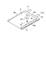
図1は、本発明に係わる薄形ポリマー電解質二次電池を示す斜視図、図2は図1の二次電池の展開斜視図、図3は図1のIII −III 線に沿う断面図、図4は図1のIV−IV線に沿う断面図である。
【0010】
図3に示すように内面側から熱融着性樹脂フィルム1、金属箔2および剛性を有する樹脂フィルム3をこの順序で積層した積層フィルムからなる外装材4内には、薄形発電要素5が収納され、前記外装材4の例えば3側辺でその内面の熱融着性樹脂フィルム1を互いに熱融着したシール部6a,6b,6cにより前記発電要素5を密封している。前記発電要素5は、正極7、セパレータであるポリマー電解質層8および負極9がこの順序で積層した構造を有する。
【0011】
前記正極7は、アルミニウム製の集電体10の両面に正極層11が担持された構造を有する。前記集電体10は、帯状アルミニウム箔からなる端子部12を有し、この端子部12にはアルミニウム製の外部正極リード13が超音波溶接によって接続されている。この外部リード13は、前記外装材4のシール部6bから外部に延出されている。
【0012】
前記負極9は、銅製の集電体14の両面に負極層15が担持された構造を有する。前記集電体14は、帯状銅箔からなる端子部16を有し、この端子部16には外部負極リード17が超音波溶接等によって接続されている。この外部リード17は、前記外装材4のシール部6bから外部に延出されている。
【0013】
孔、例えば円形孔18は図1、図4に示すように前記発電要素5の表面に対応する前記外装材4内面の熱融着性樹脂フィルム1に設けられている。この円形孔18に対向する前記外装材4の剛性を有する樹脂フィルム3部分は、前記金属箔2に対して未接着状態で、かつ切り込み部、例えば十字状切り込み部19がこの未接着状態の樹脂フィルム部分3に設けられている。
【0014】
このような薄形ポリマー電解質二次電池は、例えば次のような方法により製造される。
まず、熱融着性樹脂フィルムの所定の部位に円形孔18を打ち抜き加工し、この樹脂フィルムに金属箔を熱融着する。つづいて、剛性を有する樹脂フィルムの前記円形孔に対応する箇所に切り込み部、例えば十字状切り込み部19を十字状ポンチ等により形成した後、この樹脂フィルムを前記金属箔に前記切り込み部の箇所が未接着状態となるようにドライラミを行って例えば3層構造の帯状積層フィルム20を作製する。ひきつづき、正負極の外部端子13,17が取付けられた薄形発電要素5を短辺に平行な中央部に位置する折り曲げ線21を境にして前記円形孔18が開口されていない前記積層フィルム20部分に前記外部端子13,17が積層フィルム20の短辺の端面から延出するように載せた後、前記積層フィルム20を前記折り曲げ線21で前記発電要素5を包むように折り曲げる。その後、前記折り曲げ部を除く3つの側辺を熱シールして前記発電要素5を密封することにより図1に示す二次電池を製造する。
【0015】
前記外装材4、正極7、負極9および電解質層8は、次のような構成になっている。
1)外装材4
この外装材4は、内面側から熱融着性樹脂フィルム1、金属箔2および剛性を有する樹脂フィルム3をこの順序で積層した積層フィルムからなる。前記熱融着性樹脂としては、例えばポリエチレン(PE)、アイオノマー、エチレンビニルアセテート(EVA)等を用いることができる。前記金属箔としては、例えばAl箔、Ni箔等をも用いることができるが、薄膜化が可能なAl箔が好ましい。前記剛性を有する樹脂としては、例えばポリエチレンテレフタレート(PET)、ナイロン等を用いることができる。ただし、前記剛性を有する樹脂フィルムは2種以上のフィルムを組み合わせてもよい。
【0016】
具体的な積層フィルムとしては、シール面側から外面に向けて積層したPE/Al箔/PETの積層フィルム;PE/Al箔/ナイロンの積層フィルム;アイオノマー/Al箔/PETの積層フィルム;アイオノマー/Al箔/ナイロンの積層フィルム;アイオノマー/Ni箔/PETの積層フィルム;EVA/Al箔/PETの積層フィルム等を用いることができる。
【0017】
なお、前記外装材は積層フィルムをその内面(シール面)に熱融着性樹脂フィルムが位置するように折り曲げ、その折り曲げ線と平行な端部を熱シールして筒状物を作製し、この中に前述した薄形発電要素をその正極と電気的に接続された外部端子が一方の開口から延出し、その負極と電気的に接続された外部端子が他方の開口から延出するように収納し、前記2つの開口部を熱シールして前記発電要素を密封した構造にしてもよい。
【0018】
2)正極7
この正極7は、アルミニウム製の集電体10の両面に活物質、非水電解液及びこの電解液を保持するポリマーを含む正極層11が担持された構造を有する。
【0019】
前記活物質としては、種々の酸化物(例えばLiMn2 O4 などのリチウムマンガン複合酸化物、二酸化マンガン、例えばLiNiO2 などのリチウム含有ニッケル酸化物、例えばLiCoO2 などのリチウム含有コバルト酸化物、リチウム含有ニッケルコバルト酸化物、リチウムを含む非晶質五酸化バナジウムなど)や、カルコゲン化合物(例えば、二硫化チタン、二硫化モリブテンなど)等を挙げることができる。中でも、リチウムマンガン複合酸化物、リチウム含有コバルト酸化物、リチウム含有ニッケル酸化物を用いるのが好ましい。
【0020】
前記非水電解液は、非水溶媒に電解質を溶解することにより調製される。
前記非水溶媒としては、エチレンカーボネート(EC)、プロピレンカーボネート(PC)、ブチレンカーボネート(BC)、ジメチルカーボネート(DMC)、ジエチルカーボネート(DEC)、エチルメチルカーボネート(EMC)、γ−ブチロラクトン(γ−BL)、スルホラン、アセトニトリル、1,2−ジメトキシエタン、1,3−ジメトキシプロパン、ジメチルエーテル、テトラヒドロフラン(THF)、2−メチルテトラヒドロフラン等を挙げることができる。前記非水溶媒は、単独で使用しても、2種以上混合して使用しても良い。
【0021】
前記電解質としては、例えば過塩素酸リチウム(LiClO4 )、六フッ化リン酸リチウム(LiPF6 )、ホウ四フッ化リチウム(LiBF4 )、六フッ化砒素リチウム(LiAsF6 )、トリフルオロメタンスルホン酸リチウム(LiCF3 SO3 )、ビストリフルオロメチルスルホニルイミドリチウム[LiN(CF3 SO3 )2 ]等のリチウム塩を挙げることができる。
【0022】
前記電解質の前記非水溶媒に対する溶解量は、0.2mol/L〜2mol/Lとすることが望ましい。
前記非水電解液を保持するポリマーとしては、例えば、ポリエチレンオキサイド誘導体、ポリプロピレンオキサイド誘導体、前記誘導体を含むポリマー、ビニリデンフロライド(VdF)とヘキサフルオロプロピレン(HFP)との共重合体等を用いることができる。前記HFPの共重合割合は、前記共重合体の合成方法にも依存するが、通常、最大で20重量%前後である。
【0023】
前記正極層は、導電性を向上する観点から導電性材料を含んでいてもよい。この導電性材料としては、例えば、人造黒鉛、カーボンブラック(例えばアセチレンブラックなど)、ニッケル粉末等を挙げることができる。
【0024】
前記集電体としては、例えばアルミニウム製エキスパンドメタル、アルミニウム製メッシュ、アルミニウム製パンチドメタル等を用いることができる。
なお、前記正極は集電体の片面に正極層を担持させた構造にしてもよい。
【0025】
3)負極9
この負極9は、銅製の集電体14の両面に活物質、非水電解液及びこの電解液を保持するポリマーを含む負極層15が担持された構造を有する。
【0026】
前記活物質としては、リチウムイオンを吸蔵放出する炭素質材料を挙げることができる。かかる炭素質材料としては、例えば、有機高分子化合物(例えば、フェノール樹脂、ポリアクリロニトリル、セルロース等)を焼成することにより得られるもの、コークスや、メソフェーズピッチを焼成することにより得られるもの、人造グラファイト、天然グラファイト等に代表される炭素質材料を挙げることができる。中でも、500℃〜3000℃の温度で、常圧または減圧下にて前記メソフェーズピッチを焼成して得られる炭素質材料を用いるのが好ましい。
【0027】
前記非水電解液及び前記ポリマーとしては、前述した正極で説明したものと同様なものが用いられる。
前記負極層は、人造グラファイト、天然グラファイト、カーボンブラック、アセチレンブラック、ケッチェンブラック、ニッケル粉末、ポリフェニレン誘導体等の導電性材料、オレフィン系ポリマーや炭素繊維等のフィラーを含むことを許容する。
【0028】
前記集電体としては、例えば銅製エキスパンドメタル、銅製メッシュ、銅製パンチドメタル等を用いることができる。
なお、前記負極は集電体の片面に正極層を担持させた構造にしてもよい。
【0029】
4)ポリマー電解質層8
この電解質層8は、非水電解液及びこの電解液を保持するポリマーを含む。
前記非水電解液及び前記ポリマーとしては、前述した正極で説明したものと同様なものが用いられる。
【0030】
前記電解質層は、圧縮強度を向上させるためにSiO2 粉末のような無機フィラーを添加してもよい。
前記発電要素は、1層に限らず、2層以上を前記外装材内に収納してもよい。
【0031】
前記外装材の熱融着性樹脂フィルムに開口する孔は、円形に限らず、四角形、多角形等任意である。
前記外装材の剛性を有する樹脂フィルムに設ける切り込み部は、十字状に限らず、線状でもよい。
【0032】
次に、本発明に係わる別の薄形二次電池、例えば薄形ポリマー電解質二次電池を図5、図6を参照して説明する。
図5は、本発明に係わる別の薄形ポリマー電解質二次電池を示す斜視図、図6は図5のVI−VI線に沿う断面図である。なお、前述した図1−図4と同様な部材は同符号を付して説明を省略する。
【0033】
この薄形ポリマー電解質二次電池は、薄形発電要素5の表面に位置する外装材4の熱融着性樹脂フィルム1および剛性を有する樹脂フィルム3の一部に孔(例えば円形孔)22,23をそれぞれ対向するように開口した構造になっている。つまり、前記外装材4を構成する金属箔2は、前記円形孔22,23の箇所で内面側および外面側から露出している。
【0034】
前記孔は、円形に限らず、四角形、多角形等任意である。
前記熱融着性樹脂フィルムおよび剛性を有する樹脂フィルムの一部に開口された孔(例えば円形孔)は、必ずしも同一寸法を有さなくてもよく、例えば前記熱融着性樹脂フィルムに開口された円形孔を前記剛性を有する樹脂フィルムに開口されれた円形孔より大きくしてもよい。
【0035】
なお、薄形二次電池の体積エネルギー密度を高めるために図1または図5の外部端子13,17が延出されるシール部6bを除く互いに平行するシール部6a,6c表面側に折り曲げて固定してもよい。
【0036】
以上説明した図1−図4に示す本発明によれば、発電要素5が収納された外装材4内面の熱融着性樹脂フィルム1に円形孔18開口し、かつこの円形孔18に対向する前記外装材4の剛性を有する樹脂フィルム3部分を前記金属箔2に対して未接着状態にすると共に、この未接着状態の樹脂フィルム部分3に例えば十字状切り込み部19を設けることによって、過充電等により前記発電要素5からガスが発生して内圧が上昇しても、前記円形孔18および十字状切り込み部19が位置する前記外装材4の金属箔2の箇所で破断されて外装材4自体が破裂する前にガスを逃散することができる。
【0037】
すなわち、図7に示すように外装材4の内部にガスが発生して外装材4が膨張すると、前記外装材4の熱融着性樹脂フィルム1の円形孔18から露出する前記外装材4の金属箔2が外側に湾曲され、それに伴って円形孔18に対向する前記金属箔2に位置する未接着状態の剛性を有する樹脂フィルム3部分がその切り込み部19に沿って外側に開き、穴が形成される。その結果、前記金属箔2に対してさらにその穴に向かって外側に湾曲する力が働くため、最後にはその力に抗しきれずに破断される。
【0038】
したがって、過充電時等においてガスが発生して内圧が上昇した際に、そのガスを前記外装材を構成する金属箔の破断により外部に容易に逃散させて外装材が破裂に至るのを未然に防止することができる。このため、外装材の破裂に伴う内容物(特に電解液)の飛散を回避して、機器に直接搭載した場合における機器の損傷等を防止することが可能な薄形二次電池を提供できる。
【0039】
一方、図5、図6に示す本発明によれば薄形発電要素5が収納された外装材4の熱融着性樹脂フィルム1および剛性を有する樹脂フィルム3の一部に円形孔22,23をそれぞれ少なくとも対向するように開口することによって、過充電等によりガスが発生して外装材4が膨張すると、前記円形孔22,23の箇所で内面側および外面側から露出された前記外装材4の金属箔2は前記外側の記孔23に向かって外側に湾曲する力が働くため、最後にはその力に抗しきれずに破断される。その結果、ガスが発生して内圧が上昇した際に、そのガスを前記外装材を構成する金属箔の破断により外部に容易に逃散させて外装材が破裂に至るのを未然に防止することができる。したがって、外装材の破裂に伴う内容物(特に電解液)の飛散を回避して、機器に直接搭載した場合における機器の損傷等を防止することが可能な薄形二次電池を提供できる。
【0040】
【実施例】
以下、本発明の好ましい実施例を前述した図面を参照して詳細に説明する。
(実施例1)
<正極の作製>
アセトンにビニリデンフロライド−ヘキサフルオロプロピレン(VdF−HFP)の共重合体(エルファトケム社製商品名;KYNAR2801、共重合比[VdF:HFP]が88:12)粉末を溶解した後、このアセトン溶液にジブチルフタレート(DBP)と、活物質として組成式がLiCoO2 で表されるリチウム含有コバルト酸化物(日本重化学工業製)とを添加して正極用ペーストを調製した。つづいて、アルミニウム製メッシュからなる多孔質集電体に前記組成の正極用ペーストをナイフコータを用いて塗工し、乾燥空気で乾燥することにより前記多孔質集電体の両面に電解液未含浸正極層が形成された正極素材を作製した。
【0041】
<負極の作製>
前記正極に用いられたのと同様なビニリデンフロライド−ヘキサフルオロプロピレンの共重合体をアセトンに溶解させてアセトン溶液を調製した後、このアセトン溶液にジブチルフタレート(DBP)を添加後、活物質としてメソフェーズピッチ系炭素繊維(株式会社ペトカ社製)を添加し、混合することにより負極用ペーストを調製した。この負極用ペーストを銅製メッシュからなる多孔質集電体にナイフコータを用いて塗工し、乾燥空気により乾燥するして前記多孔質集電体の両面に電解液未含浸負極層が形成された負極素材を作製した。
【0042】
<固体ポリマー電解質層の作製>
前記正極に用いられたのと同様なビニリデンフロライド−ヘキサフルオロプロピレンとの共重合体をアセトンに溶解させてアセトン溶液を調製した後、このアセトン溶液にジブチルフタレート(DBP)を添加後、混合することによって電解質層用ペーストを調製した。前記ペーストを平滑なガラス板上に塗布した後、正負極と同様に乾燥し、前記ガラス板から剥し、電解液未含浸固体ポリマー電解質素材を作製した。
【0043】
<非水電解液の調製>
エチレンカーボネート(EC)とジメチルカーボネート(DMC)が体積比で1:1の割合で混合された非水溶媒に電解質としてのLiPF6 をその濃度が1mol/lになるように溶解させて非水電解液を調製した。
【0044】
得られた正極素材、固体ポリマー電解質素材および負極素材をこの順序で重ね、これらを130℃に加熱した剛性ロールにて加熱圧着して積層して厚さ1.0mm、外形寸法40mm×60mmの積層体を作製した。つづいて、この積層体をメタノール中に浸漬することにより前記正極素材、前記負極素材および前記ポリマー電解質素材中のDBPを溶出してそれら部材を多孔質構造の電解液未含浸発電要素とした。ひきつづき、この発電要素の正負極の多孔質集電体の帯状端子部に外部端子をそれぞれ超音波溶接等により接続した。
【0045】
次いで、厚さ50μm、外形寸法70mm×153mmの帯状アイオノマー樹脂フィルムの長辺より内側35mm、短辺より内側43mmの箇所に外径6mmの円形孔を打ち抜き加工し、この樹脂フィルムに厚さ10μmのAl箔を熱融着した。つづいて、厚さ12μmのPETフィルムの前記円形孔に対応する箇所に縦横5mmの十字状切り込み部を十字状ポンチにより形成した後、この樹脂フィルムを前記Al箔に前記切り込み部の箇所が未接着状態となるようにドライラミを行って3層構造の帯状積層フィルムを作製した。ひきつづき、正負極の外部端子が取付けられた前記電解液未含浸発電要素を前記外部端子が前記積層フィルムの短辺から延出するように載せた後、前記積層フィルムを中央でその短辺と平行に前記電解液未含浸発電要素を包むように折り曲げた。ひきつづき、前記折り曲げ部を除く幅10mmの3つの側辺を熱シールした。ただし、前記外部端子が延出される側辺を除く2側辺のうちの一方の側辺の一部を未シール部として残した。その後、前記未シール部を通して前記非水電解液を内部に注入し、未シールを再度、熱融着することにより前述した図1に示す前記積層フィルムからなる外装材4内に薄形発電要素5が密封して収納され、前記発電要素5の表面に対応する外装材4のアイオノマー樹脂フィルム1に円形孔18、この円形孔18に対向する前記外装材4のPETフィルム3に十字状の切り込み部19が設けられた厚さ1.2mm、外部端子を除く外形寸法70mm×75mm、電気容量100mAhの100個の薄形ポリマー電解質二次電池を製造した。
【0046】
(実施例2)
切り込み部の代わりに外径5mmの円形孔を外装材のPETフィルムに開口した以外、実施例1と同様な構成で、前述した図5に示す100個の薄形ポリマー電解質二次電池を製造した。
【0047】
(比較例1)
積層フィルムのアイオノマー樹脂フィルムに円形孔、PETフィルムに切り込み部を形成しない以外、実施例1と同様な寸法、電気容量を有する100個の薄形ポリマー電解質二次電池を製造した。
【0048】
得られた実施例1,2および比較例1の二次電池を内部スペースが72mm×77mm×4.0mmで外形寸法が75mm×80mm×6.0mmの外部接続端子付きポリプロピレン製ケースに各電池の正負極の外部端子が前記外部接続端子に接続されるように収納してパック型電池を組み立て。
【0049】
前記各パック型電池について、1C、3時間の条件で過充電試験を行い、電池パックのケースの厚さ方向の変形量を測定した。その結果を下記表1に示す。
表1
ケース変形個数 変形したケースの平均変形量
実施例1 0 −
実施例2 0 −
比較例1 100 2.4mm
前記表1から明らかなように実施例1,2の薄形二次電池はパック型電池とした時、全てケースの変形が認められなかった。これに対し、比較例1のの薄形二次電池はパック型電池とした時、100個中100個において変形が認められた。なお、実施例1,2のパック型電池を分解してケース内部の薄形ポリマー電解質二次電池を調べたところ、全ての二次電池は外装材を構成するアイオノマー樹脂フィルムに開口された円形孔から露出したAl箔の箇所で破断されていたことが認められた。
【0050】
【発明の効果】
以上詳述したように本発明によれば、過充電時等においてガスが発生して内圧が上昇した際に、そのガスを外部に容易に逃散させて破裂に至るのを未然に防止することが可能な安全性の高い薄形二次電池を提供できる。
【図面の簡単な説明】
【図1】本発明に係わる薄形ポリマー電解質二次電池を示す斜視図。
【図2】図2は図1の二次電池の展開斜視図。
【図3】図1のIII −III 線に沿う断面図。
【図4】図1のIV−IV線に沿う断面図。
【図5】本発明に係わる別の薄形ポリマー電解質二次電池を示す斜視図。
【図6】図5のVI−VI線に沿う断面図。
【図7】本発明に係わる薄形ポリマー電解質二次電池の作用を説明するための部分断面図。
【符号の説明】
1…熱融着性樹脂フィルム、
2…金属箔、
3…剛性を有する樹脂フィルム、
4…外装材、
5…薄形発電要素、
7…正極、
8…ポリマー電解質層、
9…負極、
13,17…外部端子、
18,22,23…円形孔、
19…切り込み部。[0001]
TECHNICAL FIELD OF THE INVENTION
The present invention relates to a thin secondary battery, and more particularly, to a thin secondary battery provided with a gas release mechanism.
[0002]
[Prior art]
In recent years, thin secondary batteries having a thickness of about 0.5 mm, such as polymer lithium ion secondary batteries, have been attracting attention as power supplies for cordless devices such as portable personal computers that emphasize small size and light weight. It is being actively promoted.
[0003]
Important elemental technologies for putting the thin secondary battery into practical use include selection of active materials for the positive electrode and the negative electrode, a technology for forming a battery, and a technology for sealing a thin power generating element pond with an exterior material. When the sealing property of the thin power generating element by the exterior material is reduced, not only does the electrolytic solution constituting the power generating element volatilize and leak to reduce the battery reaction, but also moisture easily enters from the outside to reduce the performance. Invite.
[0004]
For this reason, the conventional thin secondary battery is characterized in that a thin power generating element having a positive electrode, a separator and a negative electrode in an exterior material in which a heat-fusible resin film is disposed on the inner surface is used for collecting the positive and negative electrodes. An external terminal connected to a body is housed so as to extend from an opening edge of the exterior material, and the heat-fusible resin films are heat-sealed to each other at the opening edge, thereby attaching the power generation element to the exterior. It has a structure sealed inside the material. The exterior material is, for example, a laminated film in which a heat-fusible resin film, a barrier film such as an aluminum foil, and a rigid resin film such as a polyethylene terephthalate film are laminated at least in this order.
[0005]
However, when gas is generated inside the thin secondary battery due to overcharging or the like, the internal pressure increases. For this reason, the laminated film as an exterior material expands and eventually bursts. When a thin secondary battery ruptures, its contents (especially electrolyte) are scattered, and the device is damaged when mounted directly on the device, and the case is damaged for a battery pack. Cause damage.
[0006]
[Problems to be solved by the invention]
The present invention provides a thin secondary battery that can easily escape to the outside when a gas is generated and the internal pressure rises at the time of overcharging or the like to prevent rupture, thereby preventing the gas from exploding. It is what we are going to offer.
[0007]
[Means for Solving the Problems]
The thin secondary battery according to the present invention has a positive electrode, a separator , a negative electrode, and a non-aqueous solution in an exterior material composed of a laminated film in which a heat-fusible resin film, a metal foil, and a rigid resin film are laminated in this order from the inner surface side. A thin secondary battery in which external terminals electrically connected to the positive and negative electrodes, respectively, having a thin power generating element having an electrolyte are housed so as to extend from an opening edge of the exterior material,
The heat-fusible resin films are heat-sealed to each other at all of the opening edges of the laminated film, and the power-generating element is sealed in the housing material by the heat-sealed seal portion; to partially open the pores of the heat-fusible resin film except for the sealing portion of the timber, further the unbonded state resin film portion having a rigidity of the outer member opposite to said metal foil into the hole In addition, a cutout portion is provided in the resin film portion in the non-adhered state.
[0008]
Another thin secondary battery according to the present invention is a heat-fusible resin film from the inner surface side, a metal foil and a resin film having rigidity in an exterior material consisting of a laminated film laminated in this order, a positive electrode, a separator , a negative electrode and A thin secondary battery in which thin-type power generating elements having a non-aqueous electrolyte are housed such that external terminals electrically connected to the positive and negative electrodes respectively extend from an opening edge of the exterior material,
The heat-fusible resin films are heat-sealed to each other at all of the opening edges of the laminated film, and the power-generating element is sealed in the housing material by the heat-sealed seal portion; A hole is opened in a part of the heat-fusible resin film and a part of the rigid resin film excluding the seal portion of the material so as to at least oppose each other.
[0009]
BEST MODE FOR CARRYING OUT THE INVENTION
Hereinafter, a thin secondary battery according to the present invention, for example, a thin polymer electrolyte secondary battery will be described in detail with reference to the drawings.
1 is a perspective view showing a thin polymer electrolyte secondary battery according to the present invention, FIG. 2 is an exploded perspective view of the secondary battery shown in FIG. 1, FIG. 3 is a cross-sectional view taken along line III-III in FIG. FIG. 4 is a sectional view taken along the line IV-IV in FIG.
[0010]
As shown in FIG. 3, a thin power generating
[0011]
The
[0012]
The
[0013]
A hole, for example, a
[0014]
Such a thin polymer electrolyte secondary battery is manufactured, for example, by the following method.
First, a
[0015]
The
1)
The
[0016]
Specific laminated films include a laminated film of PE / Al foil / PET laminated from the sealing surface side to the outer surface; a laminated film of PE / Al foil / nylon; a laminated film of ionomer / Al foil / PET; A laminated film of Al foil / nylon; a laminated film of ionomer / Ni foil / PET; a laminated film of EVA / Al foil / PET can be used.
[0017]
The exterior material is formed by bending the laminated film so that the heat-fusible resin film is positioned on the inner surface (sealing surface), and heat-sealing the end parallel to the bending line to produce a cylindrical body. The thin-type power generating element described above is housed so that the external terminal electrically connected to the positive electrode extends from one opening and the external terminal electrically connected to the negative electrode extends from the other opening. The two openings may be heat-sealed to seal the power generating element.
[0018]
2)
The
[0019]
Examples of the active material include various oxides (eg, lithium manganese composite oxide such as LiMn 2 O 4 , manganese dioxide, lithium-containing nickel oxide such as LiNiO 2 , lithium-containing cobalt oxide such as LiCoO 2 , lithium Nickel-cobalt oxide, amorphous vanadium pentoxide containing lithium, etc.) and chalcogen compounds (eg, titanium disulfide, molybdenum disulfide, etc.). Among them, it is preferable to use a lithium manganese composite oxide, a lithium-containing cobalt oxide, and a lithium-containing nickel oxide.
[0020]
The non-aqueous electrolyte is prepared by dissolving an electrolyte in a non-aqueous solvent.
Examples of the non-aqueous solvent include ethylene carbonate (EC), propylene carbonate (PC), butylene carbonate (BC), dimethyl carbonate (DMC), diethyl carbonate (DEC), ethyl methyl carbonate (EMC), and γ-butyrolactone (γ- BL), sulfolane, acetonitrile, 1,2-dimethoxyethane, 1,3-dimethoxypropane, dimethyl ether, tetrahydrofuran (THF), 2-methyltetrahydrofuran and the like. The non-aqueous solvents may be used alone or as a mixture of two or more.
[0021]
Examples of the electrolyte include lithium perchlorate (LiClO 4 ), lithium hexafluorophosphate (LiPF 6 ), lithium borotetrafluoride (LiBF 4 ), lithium arsenic hexafluoride (LiAsF 6 ), and trifluoromethanesulfonic acid. Lithium salts such as lithium (LiCF 3 SO 3 ) and lithium bistrifluoromethylsulfonylimide [LiN (CF 3 SO 3 ) 2 ] can be given.
[0022]
The amount of the electrolyte dissolved in the non-aqueous solvent is desirably 0.2 mol / L to 2 mol / L.
Examples of the polymer holding the non-aqueous electrolyte include a polyethylene oxide derivative, a polypropylene oxide derivative, a polymer containing the derivative, and a copolymer of vinylidene fluoride (VdF) and hexafluoropropylene (HFP). Can be. The copolymerization ratio of the HFP depends on the method of synthesizing the copolymer, but is usually at most about 20% by weight.
[0023]
The positive electrode layer may include a conductive material from the viewpoint of improving conductivity. Examples of the conductive material include artificial graphite, carbon black (eg, acetylene black), nickel powder, and the like.
[0024]
As the current collector, for example, aluminum expanded metal, aluminum mesh, aluminum punched metal, or the like can be used.
The positive electrode may have a structure in which a positive electrode layer is supported on one surface of a current collector.
[0025]
3)
The
[0026]
Examples of the active material include carbonaceous materials that occlude and release lithium ions. Such carbonaceous materials include, for example, those obtained by firing organic polymer compounds (eg, phenolic resin, polyacrylonitrile, cellulose, etc.), those obtained by firing coke and mesophase pitch, and those made by artificial graphite. And carbonaceous materials represented by natural graphite and the like. Among them, it is preferable to use a carbonaceous material obtained by firing the mesophase pitch at a temperature of 500 ° C to 3000 ° C under normal pressure or reduced pressure.
[0027]
As the non-aqueous electrolyte and the polymer, the same ones as described for the positive electrode described above are used.
The negative electrode layer is allowed to contain conductive materials such as artificial graphite, natural graphite, carbon black, acetylene black, Ketjen black, nickel powder, and polyphenylene derivatives, and fillers such as olefin polymers and carbon fibers.
[0028]
As the current collector, for example, a copper expanded metal, a copper mesh, a copper punched metal, or the like can be used.
The negative electrode may have a structure in which a positive electrode layer is supported on one surface of a current collector.
[0029]
4) Polymer electrolyte layer 8
The electrolyte layer 8 includes a non-aqueous electrolyte and a polymer that holds the electrolyte.
As the non-aqueous electrolyte and the polymer, the same ones as described for the positive electrode described above are used.
[0030]
The electrolyte layer may include an inorganic filler such as SiO 2 powder to improve compressive strength.
The power generation element is not limited to one layer, and two or more layers may be housed in the exterior material.
[0031]
The hole opened in the heat-fusible resin film of the exterior material is not limited to a circle, but may be a rectangle, a polygon, or the like.
The cut portion provided in the rigid resin film of the exterior material is not limited to a cross shape, but may be a linear shape.
[0032]
Next, another thin secondary battery according to the present invention, for example, a thin polymer electrolyte secondary battery will be described with reference to FIGS.
FIG. 5 is a perspective view showing another thin polymer electrolyte secondary battery according to the present invention, and FIG. 6 is a sectional view taken along the line VI-VI in FIG. The same members as those in FIGS. 1 to 4 described above are denoted by the same reference numerals, and description thereof will be omitted.
[0033]
The thin polymer electrolyte secondary battery has holes (for example, circular holes) 22 in a part of the heat-fusible resin film 1 and the
[0034]
The hole is not limited to a circle, but may be a rectangle, a polygon, or the like.
The holes (for example, circular holes) opened in a part of the heat-fusible resin film and the rigid resin film do not necessarily have to have the same dimensions. For example, the holes are opened in the heat-fusible resin film. The round hole formed may be larger than the circular hole opened in the rigid resin film.
[0035]
In addition, in order to increase the volume energy density of the thin secondary battery, the
[0036]
According to the present invention shown in FIGS. 1 to 4 described above, a
[0037]
That is, as shown in FIG. 7, when gas is generated inside the
[0038]
Therefore, when a gas is generated at the time of overcharging and the internal pressure is increased, the gas is easily escaping to the outside due to the breakage of the metal foil constituting the exterior material, and the exterior material is prevented from rupture. Can be prevented. For this reason, it is possible to provide a thin secondary battery capable of avoiding scattering of contents (especially, an electrolytic solution) due to the rupture of the exterior material, and preventing damage to the device when directly mounted on the device.
[0039]
On the other hand, according to the present invention shown in FIGS. 5 and 6,
[0040]
【Example】
Hereinafter, preferred embodiments of the present invention will be described in detail with reference to the accompanying drawings.
(Example 1)
<Preparation of positive electrode>
A powder of vinylidene fluoride-hexafluoropropylene (VdF-HFP) copolymer (trade name: KYNAR2801, a copolymerization ratio [VdF: HFP] of 88:12, manufactured by Elphatochem Co., Ltd.) is dissolved in acetone, and the powder is dissolved in the acetone solution. Dibutyl phthalate (DBP) and lithium-containing cobalt oxide (manufactured by Nippon Heavy Industries, Ltd.) having a composition formula of LiCoO 2 as an active material were added to prepare a positive electrode paste. Subsequently, a positive electrode paste of the above composition was applied to a porous current collector made of an aluminum mesh using a knife coater, and dried with dry air to form a positive electrode impregnated with no electrolyte on both surfaces of the porous current collector. A positive electrode material on which a layer was formed was produced.
[0041]
<Preparation of negative electrode>
The same vinylidene fluoride-hexafluoropropylene copolymer as used for the positive electrode was dissolved in acetone to prepare an acetone solution, and then dibutyl phthalate (DBP) was added to the acetone solution. A negative electrode paste was prepared by adding and mixing mesophase pitch-based carbon fibers (manufactured by Petka Corporation). This negative electrode paste was coated on a porous current collector made of a copper mesh using a knife coater, and dried with dry air to form a negative electrode having an electrolyte-impregnated negative electrode layer formed on both surfaces of the porous current collector. The material was made.
[0042]
<Preparation of solid polymer electrolyte layer>
After dissolving the same copolymer of vinylidene fluoride-hexafluoropropylene as used for the positive electrode in acetone to prepare an acetone solution, dibutyl phthalate (DBP) is added to the acetone solution, and then mixed. Thus, a paste for an electrolyte layer was prepared. The paste was applied on a smooth glass plate, dried in the same manner as the positive and negative electrodes, and peeled off from the glass plate to prepare a solid polymer electrolyte material not impregnated with an electrolyte.
[0043]
<Preparation of non-aqueous electrolyte>
LiPF 6 as an electrolyte is dissolved in a non-aqueous solvent in which ethylene carbonate (EC) and dimethyl carbonate (DMC) are mixed at a volume ratio of 1: 1 so as to have a concentration of 1 mol / l. A liquid was prepared.
[0044]
The obtained positive electrode material, solid polymer electrolyte material and negative electrode material are stacked in this order, and they are laminated by heating and pressing with a rigid roll heated to 130 ° C. to have a thickness of 1.0 mm and an outer dimension of 40 mm × 60 mm. The body was made. Subsequently, the laminate was immersed in methanol to elute DBP in the positive electrode material, the negative electrode material, and the polymer electrolyte material, and these members were used as a porous electrolyte-impregnated power generating element having a porous structure. Subsequently, external terminals were respectively connected to the strip-shaped terminal portions of the positive and negative porous current collectors of the power generation element by ultrasonic welding or the like.
[0045]
Next, a circular hole having an outer diameter of 6 mm was punched out at a location 35 mm inward from the long side and 43 mm inward from the short side of a band-shaped ionomer resin film having a thickness of 50 μm and an outer dimension of 70 mm × 153 mm, and the resin film having a thickness of 10 μm. The Al foil was heat-sealed. Subsequently, after forming a cross-shaped notch of 5 mm in length and width with a cross-shaped punch at a position corresponding to the circular hole of the PET film having a thickness of 12 μm, the cut portion of the resin film was not adhered to the Al foil. Dry lamination was performed to obtain a three-layered band-like laminated film. Subsequently, after mounting the electrolyte-unimpregnated power generating element to which the external terminals of the positive and negative electrodes are attached so that the external terminals extend from the short side of the laminated film, the laminated film is parallel to the short side at the center. Was folded so as to enclose the electrolyte-unimpregnated power generating element. Subsequently, three sides having a width of 10 mm except for the bent portion were heat-sealed. However, a part of one of the two sides except the side from which the external terminal extends was left as an unsealed portion. Thereafter, the non-aqueous electrolyte is injected into the interior through the unsealed portion, and the unsealed portion is again heat-sealed to form the thin
[0046]
(Example 2)
With the same configuration as in Example 1 except that a circular hole having an outer diameter of 5 mm was opened in the PET film instead of the cut portion, 100 thin polymer electrolyte secondary batteries shown in FIG. 5 described above were manufactured. .
[0047]
(Comparative Example 1)
100 thin polymer electrolyte secondary batteries having the same dimensions and electric capacity as in Example 1 were manufactured except that a circular hole was not formed in the ionomer resin film of the laminated film and a cut portion was not formed in the PET film.
[0048]
Each of the obtained secondary batteries of Examples 1 and 2 and Comparative Example 1 was placed in a polypropylene case with external connection terminals having an internal space of 72 mm × 77 mm × 4.0 mm and external dimensions of 75 mm × 80 mm × 6.0 mm. The battery pack is assembled by storing the external terminals of the positive and negative electrodes so as to be connected to the external connection terminals.
[0049]
An overcharge test was performed on each of the pack-type batteries under the conditions of 1 C and 3 hours, and the amount of deformation of the battery pack case in the thickness direction was measured. The results are shown in Table 1 below.
Table 1
Case deformation number Average deformation amount of deformed case Example 10 0 −
Example 20 0 −
Comparative Example 1 100 2.4 mm
As is apparent from Table 1, when the thin secondary batteries of Examples 1 and 2 were formed into a pack type battery, no deformation of the case was observed. On the other hand, when the thin secondary battery of Comparative Example 1 was a pack-type battery, deformation was observed in 100 out of 100 batteries. Note that when the pack-type batteries of Examples 1 and 2 were disassembled and the thin polymer electrolyte secondary batteries inside the case were examined, all the secondary batteries had circular holes opened in the ionomer resin film constituting the exterior material. It was found that the Al foil was broken at the location of the Al foil exposed from the.
[0050]
【The invention's effect】
As described in detail above, according to the present invention, when gas is generated at the time of overcharging and the internal pressure increases, it is possible to prevent the gas from easily escaping to the outside and rupture. A highly safe thin secondary battery can be provided.
[Brief description of the drawings]
FIG. 1 is a perspective view showing a thin polymer electrolyte secondary battery according to the present invention.
FIG. 2 is an exploded perspective view of the secondary battery of FIG.
FIG. 3 is a sectional view taken along the line III-III in FIG. 1;
FIG. 4 is a sectional view taken along the line IV-IV in FIG. 1;
FIG. 5 is a perspective view showing another thin polymer electrolyte secondary battery according to the present invention.
FIG. 6 is a sectional view taken along the line VI-VI in FIG. 5;
FIG. 7 is a partial cross-sectional view for explaining the operation of the thin polymer electrolyte secondary battery according to the present invention.
[Explanation of symbols]
1: heat-fusible resin film,
2 ... metal foil,
3 ... a rigid resin film,
4 ... exterior material,
5. Thin power generation element,
7 ... positive electrode,
8 ... polymer electrolyte layer,
9 ... negative electrode,
13, 17 ... external terminals,
18, 22, 23 ... circular holes,
19: Notch.
Claims (2)
前記積層フィルムの開口縁部全てで前記熱融着性樹脂フィルムを互いに熱融着し、その熱融着したシール部により前記発電要素を前記外装材内に密封し、かつ
前記外装材の前記シール部を除く熱融着性樹脂フィルムの一部に孔を開口し、さらにこの孔に対向する前記外装材の剛性を有する樹脂フィルム部分を前記金属箔に対して未接着状態とすると共に、この未接着状態の樹脂フィルム部分に切り込み部を設けたことを特徴とする薄形二次電池。From the inner surface side, a thin power generating element having a positive electrode, a separator , a negative electrode, and a non-aqueous electrolyte is placed in an outer package made of a laminated film in which a heat-fusible resin film, a metal foil, and a rigid resin film are laminated in this order. An external terminal electrically connected to each negative electrode is a thin secondary battery housed so as to extend from an opening edge of the exterior material,
The heat-fusible resin films are heat-sealed to each other at all of the opening edges of the laminated film, and the power-generating element is sealed in the housing material by the heat-sealed seal portion; to partially open the pores of the heat-fusible resin film except for the sealing portion of the timber, further the unbonded state resin film portion having a rigidity of the outer member opposite to said metal foil into the hole In addition, a notched portion is provided in the resin film portion in the non-adhered state.
前記積層フィルムの開口縁部全てで前記熱融着性樹脂フィルムを互いに熱融着し、その熱融着したシール部により前記発電要素を前記外装材内に密封し、かつ
前記外装材の前記シール部を除く熱融着性樹脂フィルムおよび剛性を有する樹脂フィルムの一部に孔をそれぞれ少なくとも対向するように開口したことを特徴とする薄形二次電池。From the inner surface side, a thin power generating element having a positive electrode, a separator , a negative electrode, and a non-aqueous electrolyte is placed in an outer package made of a laminated film in which a heat-fusible resin film, a metal foil, and a rigid resin film are laminated in this order. An external terminal electrically connected to each negative electrode is a thin secondary battery housed so as to extend from an opening edge of the exterior material,
The heat-fusible resin films are heat-sealed to each other at all of the opening edges of the laminated film, and the power-generating element is sealed in the housing material by the heat-sealed seal portion; A thin secondary battery characterized in that holes are opened at least in portions of the heat-fusible resin film and the rigid resin film except for the seal portion of the material, respectively.
Priority Applications (1)
| Application Number | Priority Date | Filing Date | Title |
|---|---|---|---|
| JP26038297A JP3583592B2 (en) | 1997-09-25 | 1997-09-25 | Thin rechargeable battery |
Applications Claiming Priority (1)
| Application Number | Priority Date | Filing Date | Title |
|---|---|---|---|
| JP26038297A JP3583592B2 (en) | 1997-09-25 | 1997-09-25 | Thin rechargeable battery |
Publications (2)
| Publication Number | Publication Date |
|---|---|
| JPH11102674A JPH11102674A (en) | 1999-04-13 |
| JP3583592B2 true JP3583592B2 (en) | 2004-11-04 |
Family
ID=17347154
Family Applications (1)
| Application Number | Title | Priority Date | Filing Date |
|---|---|---|---|
| JP26038297A Expired - Fee Related JP3583592B2 (en) | 1997-09-25 | 1997-09-25 | Thin rechargeable battery |
Country Status (1)
| Country | Link |
|---|---|
| JP (1) | JP3583592B2 (en) |
Families Citing this family (12)
| Publication number | Priority date | Publication date | Assignee | Title |
|---|---|---|---|---|
| KR100369070B1 (en) * | 1999-11-09 | 2003-01-24 | 삼성에스디아이 주식회사 | Material for battery case |
| JP2004330533A (en) * | 2003-05-02 | 2004-11-25 | Toyo Kohan Co Ltd | Safety device, part equipped with it and container equipped with it |
| JP5011928B2 (en) * | 2006-10-03 | 2012-08-29 | 株式会社Gsユアサ | battery |
| CN102005617A (en) * | 2009-08-28 | 2011-04-06 | 比克国际(天津)有限公司 | Lithium-dynamic battery capable of avoiding gas inflation |
| JP5333549B2 (en) * | 2011-08-31 | 2013-11-06 | 大日本印刷株式会社 | Polymer battery packaging material and method for producing the same |
| KR101927398B1 (en) * | 2012-04-12 | 2018-12-10 | 에스케이이노베이션 주식회사 | Pouch type secondary battery |
| JP6479458B2 (en) * | 2014-12-24 | 2019-03-06 | 昭和電工パッケージング株式会社 | Method of manufacturing battery |
| JP6298032B2 (en) * | 2015-03-04 | 2018-03-20 | 太陽誘電株式会社 | Storage cell, exterior film, and storage module |
| JP6752628B2 (en) * | 2016-06-03 | 2020-09-09 | 太陽誘電株式会社 | Power storage cell and power storage module |
| JP6644650B2 (en) * | 2016-06-29 | 2020-02-12 | 太陽誘電株式会社 | Power storage cell, exterior film and power storage module |
| JP6783583B2 (en) * | 2016-08-15 | 2020-11-11 | 太陽誘電株式会社 | Power storage cell, exterior film and power storage module |
| JP6835505B2 (en) * | 2016-08-30 | 2021-02-24 | 太陽誘電株式会社 | Power storage cell, exterior film and power storage module |
-
1997
- 1997-09-25 JP JP26038297A patent/JP3583592B2/en not_active Expired - Fee Related
Also Published As
| Publication number | Publication date |
|---|---|
| JPH11102674A (en) | 1999-04-13 |
Similar Documents
| Publication | Publication Date | Title |
|---|---|---|
| JP4563264B2 (en) | Lithium secondary battery | |
| JP3554155B2 (en) | Lithium secondary battery and method of manufacturing the same | |
| JPH11162443A (en) | Assembled battery | |
| JP2000100399A (en) | Manufacture of polymer lithium secondary battery | |
| JP2004095402A (en) | Laminate battery, modular battery pack, battery pack and vehicle provided therewith | |
| JP3583592B2 (en) | Thin rechargeable battery | |
| JP4053802B2 (en) | Electrochemical devices | |
| JP3494558B2 (en) | Battery | |
| JP2002245988A (en) | Thin battery | |
| JP3464750B2 (en) | Lithium secondary battery | |
| JP4366775B2 (en) | Solid electrolyte battery | |
| JP3579227B2 (en) | Thin rechargeable battery | |
| JP3597027B2 (en) | Thin battery | |
| JPH11162436A (en) | Thin secondary battery | |
| JPH11204088A (en) | Sheet battery | |
| JP3283213B2 (en) | Lithium secondary battery | |
| JP3457856B2 (en) | Polymer electrolyte secondary battery | |
| JP3583589B2 (en) | Sheet type battery | |
| JPH11121043A (en) | Manufacture of polymer secondary battery | |
| JP2003346768A (en) | Non-aqueous electrolyte secondary battery | |
| JPH11162421A (en) | Sheet type battery | |
| JP2000173580A (en) | Thin secondary battery | |
| JP3588412B2 (en) | Thin rechargeable battery | |
| JP2000294202A (en) | Thin battery | |
| JPH11102682A (en) | Thin secondary battery |
Legal Events
| Date | Code | Title | Description |
|---|---|---|---|
| A131 | Notification of reasons for refusal |
Free format text: JAPANESE INTERMEDIATE CODE: A131 Effective date: 20040420 |
|
| A521 | Written amendment |
Free format text: JAPANESE INTERMEDIATE CODE: A523 Effective date: 20040621 |
|
| TRDD | Decision of grant or rejection written | ||
| A01 | Written decision to grant a patent or to grant a registration (utility model) |
Free format text: JAPANESE INTERMEDIATE CODE: A01 Effective date: 20040713 |
|
| A61 | First payment of annual fees (during grant procedure) |
Free format text: JAPANESE INTERMEDIATE CODE: A61 Effective date: 20040729 |
|
| R150 | Certificate of patent or registration of utility model |
Free format text: JAPANESE INTERMEDIATE CODE: R150 |
|
| LAPS | Cancellation because of no payment of annual fees |