JP3582500B2 - Ultra high pressure mercury lamp - Google Patents
Ultra high pressure mercury lamp Download PDFInfo
- Publication number
- JP3582500B2 JP3582500B2 JP2001153740A JP2001153740A JP3582500B2 JP 3582500 B2 JP3582500 B2 JP 3582500B2 JP 2001153740 A JP2001153740 A JP 2001153740A JP 2001153740 A JP2001153740 A JP 2001153740A JP 3582500 B2 JP3582500 B2 JP 3582500B2
- Authority
- JP
- Japan
- Prior art keywords
- quartz glass
- lamp
- temperature
- discharge
- discharge vessel
- Prior art date
- Legal status (The legal status is an assumption and is not a legal conclusion. Google has not performed a legal analysis and makes no representation as to the accuracy of the status listed.)
- Expired - Lifetime
Links
Images

Classifications
-
- H—ELECTRICITY
- H01—ELECTRIC ELEMENTS
- H01J—ELECTRIC DISCHARGE TUBES OR DISCHARGE LAMPS
- H01J61/00—Gas-discharge or vapour-discharge lamps
- H01J61/02—Details
- H01J61/30—Vessels; Containers
- H01J61/302—Vessels; Containers characterised by the material of the vessel
-
- H—ELECTRICITY
- H01—ELECTRIC ELEMENTS
- H01J—ELECTRIC DISCHARGE TUBES OR DISCHARGE LAMPS
- H01J61/00—Gas-discharge or vapour-discharge lamps
- H01J61/84—Lamps with discharge constricted by high pressure
- H01J61/86—Lamps with discharge constricted by high pressure with discharge additionally constricted by close spacing of electrodes, e.g. for optical projection
Landscapes
- Vessels And Coating Films For Discharge Lamps (AREA)
- Discharge Lamps And Accessories Thereof (AREA)
- Glass Compositions (AREA)
Description
【0001】
【発明の属する技術分野】
この発明は高圧水銀ランプに関する。特に、放電容器内に0.15mg/mm3以上の水銀が封入されて点灯時の水銀蒸気圧が150気圧以上にもなるショートアーク型超高圧水銀ランプに関する。
【0002】
【従来の技術】
投射型プロジェクター装置は、矩形状のスクリーンに対して均一に、しかも十分な演色性を追って画像を照明させることが要求され、このため、光源としては水銀や金属ハロゲン化物を封入させたメタルハライドランプが使われている。また、最近では、より一層の小型化、点光源化が進められ、電極間距離も極めて小さいものが実用化されてきている。
【0003】
このような背景のもと、最近では、メタルハライドランプに代わって、極めて高い水銀蒸気圧、例えば、200バール(約197気圧)以上を持つランプが提案されている。これは水銀蒸気圧を高くすることで、アークの広がりを抑えると共に、より一層の光出力の向上を図るというものであり、例えば、特開平2−148561号(米国特許第5,109,181)、特開平6−52830号(米国特許第5,497,049)に開示されている。
【0004】
このようなプロジェクター装置に使われる光源装置は、鮮明な画像を投射するという関係上、放電ランプが失透するということは大きな問題となる。その一方で、最近は、DMD(マイクロミラーデバイス)を使ったDLP(デジタルライトプロセッサ)方式が採用されたことにより、液晶パネルを使う必要がなくなり、これにより、より一層小型のプロジェクター装置が注目されつつある。つまり、プロジェクター装置用の放電ランプは、高い光出力や照度維持率が要求される反面、プロジェクター装置の小型化に伴い、放電ランプもより小型が求められ、その点灯条件もより厳しい内容が要求されつつある。
【0005】
ここで、放電容器の材料としては、紫外光の透過特性から一般に石英ガラスが採用されるが、この石英ガラスは、ランプ製造段階において残留歪みを発生させることがある。このような残留歪みは放電ランプの高い光出力や高い照度維持率に影響を及ぼす。
そして、従来のランプ製造工程では、このような残留歪みを除去あるいは低減するために、放電容器そのものを高温加熱処理(アニール)することが行われていた。
【0006】
また、石英ガラスの残留歪みを除去するだけでなく、石英ガラスの結晶構造そのものを制御するという技術も存在する。これは発生した残留歪みを除去するのではなく、もともと歪みの発生しない石英ガラスを提供しようという考えによるものである。この結晶構造の制御とは、具体的には、仮想温度を制御することであるが、この技術を使うことにより、石英ガラスの失透を効果的に低減できることが知られている。
このような技術は、例えば、特開平7−215731号に開示されている。
【0007】
ところが、上記特開平7−215731号に開示される技術にもとづいた放電ランプをプロジェクター装置の光源として点灯試験してみると、実際には、良好な点灯が必ずしもできていないということが判明した。
具体的には、放電ランプの点灯時間の経過とともに放電容器が失透して照度維持率を低下させたり、また、放電容器にクラック等の破損を生じさせるというものであり、このクラックは場合によっては、放電容器が破壊するという大きな事態まで実験レベルで生じている。
【0008】
【発明が解決しようとする課題】
そこで、この発明が解決しようとする課題は、石英ガラスからなる放電容器に0.15mg/mm3以上の水銀を封入するプロジェクター装置用の超高圧水銀ランプであって、放電容器の失透と放電容器の破損をともに解決できる新規な構造を提供することである。
【0009】
上記課題を解決するために、この発明の超高圧水銀ランプは、プロジェクター装置用の放電ランプであって、石英ガラスからなる放電容器に一対の電極が対向配置しており、この放電容器に0.15mg/mm3以上の水銀と、ハロゲンを封入している構造において、さらに、前記石英ガラスは仮想温度が1000〜1250℃であって、かつ、アルカリ金属の総含有量が0.1〜3重量(wt.)ppm、アルミニウム含有量が1〜30重量(wt.)ppmであることを特徴とする。
【0010】
【作用】
本発明者は、上記課題を解決するために鋭意検討した結果、放電容器に0.15mg/mm3以上の水銀とハロゲンガスを封入するプロジェクター装置用の超高圧水銀ランプにおいては、石英ガラスの仮想温度(結晶構造)を制御するだけでは、放電容器の失透と破損という2つの問題を両方とも解決できないことに気づいた。
そして、点灯時のランプ内圧(水銀蒸気圧)が極めて高いという特有の事情を考慮して、石英ガラスの仮想温度の規定に加えて、石英ガラスに含有されるアルカリ金属総含有量とアルミニウム含有量を規定することが問題解決に有効であることを見出した。
【0011】
ここで、上記仮想温度を規定した先行文献(特開平7−215731号)は、高圧水銀ランプ、エキシマランプ等への採用を示唆する記載はいちおうあるが、実際の説明は低圧水銀ランプを前提とするものである。
しかも、本発明は、点灯時の水銀蒸気圧がせいぜい1〜10気圧程度の一般的な水銀ランプではなく、封入量水銀が0.15mg/mm3以上であり点灯時には150気圧以上もの極めて高圧な状態を作るランプを対象としている。また、放電容器の内容積(放電空間の内容積)も、例えば、70mm3以下をいう極めて小型な放電ランプであって、一般の高圧水銀ランプからは比較できないぐらい異質な点灯状態を有するものである。
つまり、上記先行文献に記載する放電ランプは、仮想温度に関する言及があるものの、それは低圧水銀ランプを前提とするものであり、仮に、高圧水銀ランプへの適用に一応言及していたとしても、それはせいぜい1〜10気圧程度のきわめて一般的な高圧水銀ランプを対象にするものであり、そこに記載される技術を本発明の高圧水銀ランプにそのまま適用しても必ずしも同様の効果を得ることはできないことを本発明者らは見出した。
【0012】
そして、本発明者はさらに鋭意検討を積み重ねた結果、石英ガラス中に存在するアルカリ金属(ナトリウム、カリウムなど)元素が、石英ガラスの構成要素であるシリコン(Si)と酸素(O)の化学結合に混入しており、このアルカリ金属が放電容器内に大量に存在する水銀とハロゲン元素の影響を受けて、放電容器の失透と破損を導いていることを見出し、放電容器を構成する石英ガラスの中に、アルミニウムを混入させることで、上記アルカリ金属による悪作用を防止できることを発明したのである。
【0013】
【発明の実施の形態】
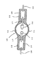
図1に本発明の超高圧水銀ランプ(以下、単に「放電ランプ」ともいう)の全体構成を示す。
放電ランプ10は、石英ガラスからなる放電容器11によって形成された大略球形の放電空間部12を有し、この放電空間部12内には、陰極13と陽極14が互いに対向するよう配置されている。また、放電空間部12の両端部から伸びるよう各々封止部15が形成され、これらの封止部15内には、通常モリブデンよりなる導電用金属箔16が、例えばピンチシールにより気密に埋設されており、陰極13および陽極14の各々を先端に有する電極棒17の基端部が、当該導電用金属箔16の一端部に配置された状態で溶接されて電気的に接続されると共に、他端部には、外部に突出する外部リード棒18が溶接されている。
【0014】
放電空間部12内には、水銀と、希ガスと、ハロゲンガスが封入されている。水銀は、必要な可視光波長、例えば、波長360〜780nmという放射光を得るためのもので、0.15mg/mm3以上封入されている。この封入量は、温度条件によっても異なるが、点灯時150気圧以上で極めて高い蒸気圧となる。また、水銀をより多く封入することで点灯時の水銀蒸気圧200気圧以上、300気圧以上という高い水銀蒸気圧の放電ランプを作ることができ、水銀蒸気圧が高くなるほどプロジェクター装置に適した光源を実現することができる。
希ガスは、例えば、アルゴンガスが約13kPa封入され、点灯始動性を改善するためのものである。
ハロゲンは、臭素、塩素、沃素などが水銀その他の金属との化合物の形態で封入され、ハロゲンの封入量は、例えば、10−6〜10−2μmol/mm3の範囲から選択できるものであって、その機能はハロゲンサイクルを利用した長寿命化であるが、本発明の放電ランプのように極めて小型で高い内圧を有するものは、このようなハロゲンを封入することも、後述する放電容器の破損、失透という現象に影響を及ぼしていることが考えられる。
【0015】
このような放電ランプの数値例を示すと、例えば、発光部の最大外径9.5mm、電極間距離1.5mm、発光管内容積75mm3、管壁負荷1.5W/mm3、定格電圧80V、定格電力150Wである。
そして、この放電ランプは、前記したプロジェクター装置やオーバーヘッドプロジェクターのようなプレゼンテーション用機器に搭載され、演色性の良い放射光を提供することができる。
【0016】
本発明の超高圧水銀ランプの第一の特徴は、放電容器11を構成する石英ガラスの仮想温度を1000〜1250℃の範囲に規定したことである。
ここで、「仮想温度」とは、石英ガラスの構造を示す尺度であって、構造決定温度ということもできる。すなわち、ガラスはその熱処理条件によって構造が全く異なるものとなる。例えば、ある高温Tで熱平衡状態にあるガラスを室温まで急速に冷却すると、ガラスの構造は温度Tにおける状態が保持されたまま凍結されることになり、この場合にこの高温Tをそのガラスの仮想温度という。また同じように高温Tで熱平衡状態にあるガラスを急速ではなく、徐々に低温状態まで冷却させた場合は、仮想温度は室温に近い温度となってしまう。
【0017】
このように石英ガラスを仮想温度により結晶構造を制御するためには、熱平衡状態とそこからの冷却方法によるわけで、前記のように、高温加熱による熱平衡状態から急速に冷却することで熱平衡状態時の温度に近い仮想温度を得ることが可能となる。
ある仮想温度の石英ガラスを生成するための条件の一例を以下にあげる。
▲1▼.石英ガラスを1150℃で20分間加熱した後に、0.1℃/分のペースで900℃まで急速冷却することで仮想温度「1080℃」の石英ガラスを得ることができる。
▲2▼.石英ガラスを1200℃で5分間加熱した後に、15.0℃/分のペースで800℃まで急速冷却することで仮想温度「1237℃」の石英ガラスを得ることができる。
▲3▼.石英ガラスを1050℃で120分間加熱した後に、0.5℃/分のペースで850℃まで急速冷却することで仮想温度「1192℃」の石英ガラスを得ることができる。
▲4▼.石英ガラスを1100℃で60分間加熱した後に、1.5℃/分のペースで800℃まで急速冷却することで仮想温度「1180℃」の石英ガラスを得ることができる。
これらは、一例であり、他のさまざまな条件により異なる仮想温度の石英ガラスを生成することが可能となる。
そして、このような仮想温度で規定される石英ガラスの結晶構造を生成する工程は、一般には、電極を発光管へ封着して放電ランプの形状が完成した後に行う。
【0018】
なお、前記したように、従来の高圧水銀ランプでは、放電容器となる石英ガラス管に電極を取付けて封止した後に、除歪処理として高温加熱処理(アニール)をしていた。
この処理は、石英ガラスに存在する「歪み」を除去する処理であって、本願発明のように石英ガラスの結晶構造そのものを制御する処理ではない。
また、除歪処理としての高温加熱処理は高温で長時間の保持が必要となる。一例をあげると、1000℃で10時間以上もの加熱処理を続けなければならない。
つまり、仮想温度により結晶構造を制御することは、従来行っていた除歪処理とは処理目的が全く異なるばかりか、処理時間の簡素性や短時間性という意味においても有利なものとなる。
【0019】
ここで、ある石英ガラスの仮想温度を測定する方法として、赤外吸収スペクトル法(FT−IR)やラマン分光法が存在する。赤外吸収スペクトル法は石英ガラスのSiーO結合の伸縮モードを示すピークのシフト量から、また、ラマン分光法は各環構造に対応するピーク強度比から、ガラスの仮想温度を見積もることが可能である。
このうち赤外分光法について、具体的に簡単に説明すると、A.Agarwalらが仮想温度を算出するための下記の式を導いている。
仮想温度(K)=43809.21/(ピーク波数−2228.64)…(式1)
そして、測定対象の石英ガラスが2260cm−1付近において、最も透過率の低くなる波数をピーク波数として、式1に挿入することで仮想温度を求めることができる。
【0020】
本発明の高圧水銀ランプの第二の特徴は、放電容器11を構成する石英ガラスがアルカリ金属の総含有量は0.1〜3.0重量ppm、アルミニウムの含有量が1.0〜30重量ppmの範囲内としたことである。
ここで、「アルカリ金属」とは、リチウム(Li)、ナトリウム(Na)、カリウム(K)のことを意味しており、これら元素の合計含有量が上記範囲内のものでなければならない。
アルカリ金属が必要な理由は、石英ガラスの粘性を確保するためであり、石英ガラスは高温状態においてランプ形状加工や電極部の封止工程において、ある程度のガラス粘性を必要とするからである。
そして、アルカリ金属の含有量を0.1重量ppmより小さくさせる場合には、極めて特殊な純化処理が必要になるなど著しく高い製造コストを要し、また、アルカリ金属の含有量が3.0重量ppmを越える場合には、石英ガラス中に逆に多く存在することになって、放電容器の失透、破損の原因となってしまう。このため、アルカリ金属の総含有量は0.1〜3.0重量ppmの範囲が最適範囲となる。
【0021】
次に、アルミニウムを含有する理由について述べる。
アルカリ金属は、上記のように石英ガラスの粘性を作るために必要なものであるが、ランプ点灯中においてはガラス内を移動して、ガラスのSi−O構造を切断したり、不純物サイトを形成してしまい、結果として、放電ランプの破損や放電容器の失透を招くことになる。
これに対して、アルミニウムがガラス中に存在する場合、アルミニウムがSi原子と置換してマイナスイオン領域を形成し、ガラス中のアルカリイオン(正イオン)をそのマイナス域に拘束することになる。
つまり、適度なアルミニウムの添加は、アルカリイオンの移動を低減させることになる。
【0022】
このようにアルミニウムの添加は、ガラス中におけるアルカリイオンの移動を捕捉する機能を有し、この機能を果たすための最適範囲という観点から、その含有量は1.0〜30重量ppmと規定された。
アルミニウムの含有量が1.0重量ppm以下の場合は、アルカリイオンの捕捉機能を十分に果たすだけの量が少なく、また、30重量ppm以上の場合はアルカリイオンの捕捉機能はあるものの不純物としても機能してしまい、アルカリ金属の場合と同様に、放電容器の破損、失透を招くことになる。
【0023】
次に、本発明の超高圧水銀ランプの作用効果に関する実験について説明する。使用した高圧水銀ランプは、発光部の最大外径9.4mm、電極間距離1.3mm、発光管内容積75mm3、封入水銀量0.25mg/mm3、封入ハロゲンと封入量10−4μmol/mm3、管壁負荷1.5W/mm3、定格電圧80V、定格電力150Wである。
実験は、仮想温度、アルカリ濃度、アルミニウム濃度を変えた放電ランプ50本(本発明の実施例26本、本発明に含まれない比較例24本)の各々について、放電容器の破損状態と白濁形成を観察した。
放電容器の破損状態については、放電ランプを2分間点灯させた後40秒間消灯させるという動作を10回繰り返した後、放電容器の破損状態を観察して、破損と認められる割合を記録している。そして、各々の放電ランプに対して、数十回ずつこの点灯実験を行い、その中から破損の発生確率を求めている。ここで、「破損」とは、放電ランプにクラックが生じる場合や、放電ランプが破壊する場合をいう。
また、白濁形成についても同様に、各放電ランプについて、各々50時間点灯させた後の放電容器の白濁面積を観察するとともに、各ランプに対して数十回の点灯させた場合の平均値を記録している。
【0024】
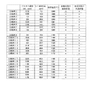
図2は上記仕様の超高圧水銀ランプのうち、実施例1〜26の実験結果を表す。
アルカリ濃度はリチウム、ナトリウム、カリウムの総含有量を示し、また、放電容器の破損状態は数十回の点灯実験の比率として、破損率1%未満のものを「○」、1〜5%のものを「△」、5%以上のものを「×」として記録した。
また、放電容器の失透状態については、同じく数十回の点灯実験の平均値として、発光管部に、0.5cm2以上の失透が生じたものを「×」、0.1〜0.5cm2の失透が生じたものを「△」、0.1cm2未満の失透が生じたものを「○」とした。
【0025】
図2の結果から、仮想温度が1050〜1250℃、アルカリ濃度が0.11〜2.94重量.ppm、アルミニウム濃度が2.3〜29.8重量ppmの範囲であれば、放電ランプの放電容器は破損も失透も生じていないことが示される。
なお、種々の測定誤差を考慮すると、この実験から、仮想温度が1000〜1250℃、アルカリ濃度が0.1〜3.0重量ppm、アルミニウム濃度が1.0〜30重量ppmが発明のる範囲と規定することができる。
【0026】
次に、図3に、放電ランプ(比較例1〜24)の実験結果を示す。
比較例1〜8は、アルカリ濃度とアルミニウム濃度は上記範囲内のもので、仮想温度が上記範囲から外れる場合の放電ランプについて行った実験結果である。実験より、仮想温度が1250℃にもっとも近い1263℃である比較例4についても、放電容器の破損状態、放電容器の失透状態のいずれにおいても好ましくない結果を招いている。
この結果、アルカリ濃度やアルミニウム濃度を良好な範囲のものとしても、仮想温度が1260℃(同様に種々の測定誤差を考慮する)を越えると放電ランプとして好ましくないことが示される。
【0027】
また、比較例9〜16は、仮想温度とアルミニウム濃度は発明の範囲内のものであるが、アルカリ金属が発明の範囲外の放電ランプについて行った実験結果を示す。具体的には、アルカリ金属の含有量が3.0重量ppmを越える場合について実験を行った。
実験より、アルカリ金属含有量が、3.0重量ppmにもっとも近い3.6重量ppmである比較例9についても、放電容器の破損状態、放電容器の失透状態のいずれにおいても好ましくない結果を招いている。
この結果、仮想温度やアルミニウム濃度を良好な範囲のものとしても、アルカリ金属含有量が3.0重量ppm(同様に種々の測定誤差を考慮する)を越えると放電ランプとして好ましくないことが示される。
【0028】
さらに、比較例17〜24として、仮想温度をアルカリ濃度は発明範囲内のものであるが、アルミニウム含有量が30重量ppmを越える場合について実験を行った。
実験より、アルミニウム含有量が30.0重量ppmにもっとも近い32.8重量ppmである比較例19についても、放電容器の破損状態、放電容器の失透状態のいずれにおいても好ましくない結果を招いている。
この結果、仮想温度やアルカリ濃度を良好な範囲のものとしても、アルミニウム含有量が30.0重量ppm(同様に種々の測定誤差を考慮する)を越えると放電ランプとして好ましくないことが示される。
【0029】
以上、説明したように、本発明の高圧水銀ランプは、放電容器に0.15mg/mm3以上の水銀を封入してプロジェクター装置の光源として使われる小型のランプであって、放電容器を構成する石英ガラスの仮想温度、アルカリ含有量、アルミニウム含有量を所定の範囲に規定することで、放電容器の破損や白濁という問題を良好に解決することができる。
【0030】
なお、石英ガラスの仮想温度、アルカリ含有量、アルミニウム含有量の上記規定は、本質的には放電ランプの発光管部での規定を意味するが、発光空間内容積70mm3以下という小型の放電ランプにおいては、封止部も含めて放電容器全体で考慮することができる。
【0031】
さらに、本発明においては、放電容器を構成する石英ガラスの仮想温度について規定しているが、放電容器の発光部と封止部において仮想温度を変化させることもできる。
これは、ランプ点灯中において、発光部の温度は封止部の温度に比べて高温になるためであり、発光部については、仮想温度1050〜1250℃、さらには、1200℃〜1250℃の範囲で作ることが好ましい。
【0032】
また、本発明の超高圧水銀ランプは、ハロゲンガスを封入しない場合もあり、また、水銀以外の金属、希土類金属などを封入する場合もある。
また、本発明の超高圧水銀ランプは、直流点灯に限定されるものではなく、交流点灯のものにも適用することができる。
また、本発明の超高圧水銀ランプは、ランプの長手軸を垂直に配置する場合、水平に配置する場合、斜めに配置する場合などいろいろな点灯姿勢のものに適用することができる。
また、本発明の超高圧水銀ランプは、凹面反射鏡に内蔵されるものであり、凹面反射鏡に前面ガラスなどを設けて密閉、あるいはほぼ密閉状態にする場合や、前面ガラスを設けることなく開放状態にする構造を採用することができる。
【図面の簡単な説明】
【図1】本発明の超高圧水銀ランプの全体構成を示す。
【図2】本発明の超高圧水銀ランプの効果を示す。
【図3】本発明の超高圧水銀ランプと比較した説明を示す。
【符号の説明】
10 放電ランプ
11 放電容器
12 発光空間部
13 陰極
14 陽極
15 封止部
16 金属箔
17 電極棒
18 外部リード[0001]
TECHNICAL FIELD OF THE INVENTION
The present invention relates to a high-pressure mercury lamp. In particular, the present invention relates to a short arc type ultra-high pressure mercury lamp in which mercury of 0.15 mg / mm 3 or more is sealed in a discharge vessel and a mercury vapor pressure at the time of lighting becomes 150 atm or more.
[0002]
[Prior art]
Projection-type projector devices are required to illuminate images on a rectangular screen uniformly and with sufficient color rendering properties. For this reason, a metal halide lamp in which mercury or a metal halide is sealed is used as a light source. It is used. In recent years, further miniaturization and the use of point light sources have been promoted, and those having extremely small distances between electrodes have been put to practical use.
[0003]
Against this background, instead of metal halide lamps, lamps having an extremely high mercury vapor pressure, for example, 200 bar (about 197 atm) or more have been proposed. This is to increase the mercury vapor pressure, thereby suppressing the spread of the arc and further improving the light output. For example, Japanese Patent Application Laid-Open No. 2-148561 (US Pat. No. 5,109,181) And JP-A-6-52830 (U.S. Pat. No. 5,497,049).
[0004]
In the light source device used in such a projector device, the fact that the discharge lamp is devitrified is a serious problem in terms of projecting a clear image. On the other hand, recently, with the adoption of a DLP (Digital Light Processor) system using a DMD (Micro Mirror Device), there is no need to use a liquid crystal panel, and as a result, an even smaller projector device has been attracting attention. It is getting. In other words, a discharge lamp for a projector device requires a high light output and an illuminance maintenance factor, but with the downsizing of the projector device, a smaller discharge lamp is also required, and its lighting conditions are also required to be stricter. It is getting.
[0005]
Here, quartz glass is generally used as the material of the discharge vessel because of the transmittance of ultraviolet light, but this quartz glass may cause residual distortion in the lamp manufacturing stage. Such residual distortion affects a high light output and a high illuminance maintenance rate of the discharge lamp.
In the conventional lamp manufacturing process, a high-temperature heating treatment (annealing) of the discharge vessel itself has been performed in order to remove or reduce such residual distortion.
[0006]
In addition, there is a technique that not only removes residual distortion of quartz glass but also controls the crystal structure itself of quartz glass. This is based on the idea not to remove the generated residual strain but to provide quartz glass which does not originally generate distortion. Specifically, the control of the crystal structure is to control a virtual temperature. It is known that the use of this technique can effectively reduce the devitrification of quartz glass.
Such a technique is disclosed, for example, in JP-A-7-215731.
[0007]
However, when a lighting test was performed on a discharge lamp based on the technique disclosed in the above-mentioned Japanese Patent Application Laid-Open No. 7-215731 as a light source of the projector device, it was found that in practice, good lighting was not necessarily achieved.
Specifically, the discharge vessel is devitrified with the elapse of the lighting time of the discharge lamp, and the illuminance maintenance ratio is reduced, or the discharge vessel is damaged, such as cracks. Has occurred at the experimental level up to the point where the discharge vessel is destroyed.
[0008]
[Problems to be solved by the invention]
An object to be solved by the present invention is to provide an ultra-high pressure mercury lamp for a projector device in which 0.15 mg / mm 3 or more of mercury is sealed in a discharge vessel made of quartz glass. An object of the present invention is to provide a novel structure that can solve both damages of a container.
[0009]
In order to solve the above-mentioned problem, an ultrahigh-pressure mercury lamp according to the present invention is a discharge lamp for a projector device, in which a pair of electrodes are arranged opposite to a discharge vessel made of quartz glass. In a structure in which mercury of 15 mg / mm 3 or more and halogen are sealed, the quartz glass has a fictive temperature of 1000 to 1250 ° C. and a total content of alkali metals of 0.1 to 3 wt. (Wt.) Ppm and an aluminum content of 1 to 30 ppm by weight (wt.).
[0010]
[Action]
The present inventors have conducted intensive studies to solve the above-mentioned problems. As a result, in an ultra-high pressure mercury lamp for a projector device in which mercury and halogen gas of 0.15 mg / mm 3 or more are sealed in a discharge vessel, a virtual quartz glass is used. It has been found that simply controlling the temperature (crystal structure) cannot solve both of the two problems of devitrification and breakage of the discharge vessel.
Considering the unique circumstances that the lamp internal pressure (mercury vapor pressure) during lighting is extremely high, in addition to defining the fictive temperature of quartz glass, the total alkali metal content and aluminum content of quartz glass Was found to be effective in solving the problem.
[0011]
Here, the prior art (Japanese Patent Application Laid-Open No. 7-215731) which defines the above-mentioned virtual temperature has a statement suggesting the adoption to a high-pressure mercury lamp, an excimer lamp, and the like, but the actual explanation assumes a low-pressure mercury lamp. Is what you do.
Moreover, the present invention is not an ordinary mercury lamp at most about 1 to 10 atmospheres of mercury vapor pressure during lighting, also of very high filling quantity mercury least 150 atm during striking is the 0.15 mg / mm 3 or more It is intended for lamps that make states. Further, the internal volume of the discharge vessel (the internal volume of the discharge space) is, for example, an extremely small discharge lamp having a size of 70 mm 3 or less, which has a different lighting state that cannot be compared with a general high-pressure mercury lamp. is there.
In other words, although the discharge lamp described in the above-mentioned prior art references mentions a virtual temperature, it is based on a low-pressure mercury lamp, and even if it mentions application to a high-pressure mercury lamp, it does not It is intended for a very common high-pressure mercury lamp of at most about 1 to 10 atm. Even if the technology described therein is directly applied to the high-pressure mercury lamp of the present invention, the same effect cannot always be obtained. The present inventors have found that.
[0012]
As a result of further intensive studies, the present inventor has found that an alkali metal (sodium, potassium, etc.) element present in quartz glass is chemically bonded to silicon (Si) and oxygen (O), which are constituents of quartz glass. Found that this alkali metal is affected by mercury and halogen elements present in large quantities in the discharge vessel, leading to devitrification and breakage of the discharge vessel. The inventors have invented that by mixing aluminum into them, the adverse effect of the alkali metal can be prevented.
[0013]
BEST MODE FOR CARRYING OUT THE INVENTION
FIG. 1 shows the overall configuration of an ultra-high pressure mercury lamp (hereinafter, also simply referred to as “discharge lamp”) of the present invention.
The
[0014]
Mercury, a rare gas, and a halogen gas are sealed in the discharge space 12. Mercury is used to obtain a required visible light wavelength, for example, emission light having a wavelength of 360 to 780 nm, and is enclosed in 0.15 mg / mm 3 or more. The amount of sealing varies depending on the temperature conditions, but becomes extremely high at 150 atm or more during lighting. In addition, by filling in more mercury, a discharge lamp having a high mercury vapor pressure of 200 atm or more and 300 atm or more at the time of lighting can be produced. As the mercury vapor pressure becomes higher, a light source suitable for a projector device is formed. Can be realized.
The rare gas is, for example, filled with about 13 kPa of argon gas to improve the lighting startability.
Halogen is sealed in the form of a compound of bromine, chlorine, iodine and the like with mercury and other metals, and the amount of halogen can be selected, for example, from the range of 10 −6 to 10 −2 μmol / mm 3. Its function is to extend the life of the lamp using a halogen cycle.However, a discharge lamp such as the discharge lamp of the present invention, which is extremely small and has a high internal pressure, can be filled with such a halogen, and can be used in a discharge vessel described later. It is considered that this is affecting the phenomenon of breakage and devitrification.
[0015]
As a numerical example of such a discharge lamp, for example, the maximum outer diameter of the light emitting portion is 9.5 mm, the distance between the electrodes is 1.5 mm, the arc tube inner volume is 75 mm 3 , the tube wall load is 1.5 W / mm 3 , and the rated voltage is 80 V , Rated power 150 W.
The discharge lamp is mounted on a presentation device such as the projector device or the overhead projector described above, and can provide emitted light having good color rendering properties.
[0016]
The first feature of the ultra-high pressure mercury lamp of the present invention is that the fictive temperature of the quartz glass constituting the
Here, the “virtual temperature” is a scale indicating the structure of quartz glass, and can also be referred to as a structure determining temperature. That is, the glass has a completely different structure depending on the heat treatment conditions. For example, when a glass in a thermal equilibrium state at a certain high temperature T is rapidly cooled to room temperature, the structure of the glass is frozen while maintaining the state at the temperature T. In this case, the high temperature T is reduced to a virtual value of the glass. It is called temperature. Similarly, when the glass in the thermal equilibrium state at the high temperature T is not cooled rapidly but gradually cooled to the low temperature state, the virtual temperature becomes a temperature close to room temperature.
[0017]
In order to control the crystal structure of the quartz glass by the virtual temperature in this manner, the thermal equilibrium state and the cooling method therefrom are used. It is possible to obtain a virtual temperature close to the temperature.
An example of conditions for producing quartz glass at a certain virtual temperature is described below.
▲ 1 ▼. After the quartz glass is heated at 1150 ° C. for 20 minutes, it is rapidly cooled to 900 ° C. at a rate of 0.1 ° C./min to obtain quartz glass having a virtual temperature of “1080 ° C.”.
▲ 2 ▼. After heating the quartz glass at 1200 ° C. for 5 minutes, the quartz glass is rapidly cooled to 800 ° C. at a rate of 15.0 ° C./min, whereby a quartz glass having a virtual temperature of “1237 ° C.” can be obtained.
(3). After heating the quartz glass at 1050 ° C. for 120 minutes, the quartz glass is rapidly cooled to 850 ° C. at a rate of 0.5 ° C./min, whereby a quartz glass having a virtual temperature of “1192 ° C.” can be obtained.
▲ 4 ▼. After heating the quartz glass at 1100 ° C. for 60 minutes, the quartz glass is rapidly cooled to 800 ° C. at a rate of 1.5 ° C./min to obtain quartz glass having a virtual temperature of “1180 ° C.”.
These are only examples, and it is possible to produce quartz glass having different fictive temperatures depending on various other conditions.
The step of generating the crystal structure of quartz glass defined by such a virtual temperature is generally performed after the electrodes are sealed to the arc tube to complete the shape of the discharge lamp.
[0018]
As described above, in the conventional high-pressure mercury lamp, a high-temperature heating treatment (annealing) is performed as a strain removing treatment after attaching and sealing the electrode to a quartz glass tube serving as a discharge vessel.
This process is a process for removing “distortion” existing in the quartz glass, and is not a process for controlling the crystal structure itself of the quartz glass as in the present invention.
In addition, the high-temperature heat treatment as the strain removing treatment requires holding at a high temperature for a long time. As an example, heat treatment at 1000 ° C. for more than 10 hours must be continued.
In other words, controlling the crystal structure by the virtual temperature not only has a completely different processing purpose from the strain removal processing conventionally performed, but also is advantageous in terms of simplicity and short processing time.
[0019]
Here, as a method of measuring the virtual temperature of a certain quartz glass, there are an infrared absorption spectroscopy (FT-IR) and a Raman spectroscopy. Infrared absorption spectroscopy can estimate the fictive temperature of the glass from the shift amount of the peak indicating the stretching mode of the Si-O bond of quartz glass, and Raman spectroscopy can estimate the fictive temperature of the glass from the peak intensity ratio corresponding to each ring structure It is.
Among them, the infrared spectroscopy will be specifically described briefly. Agarwal et al. Have derived the following equation for calculating the virtual temperature.
Fictive temperature (K) = 43809.21 / (peak wave number-2228.64) (Equation 1)
Then, when the quartz glass to be measured is near 2260 cm −1 , the fictive temperature can be obtained by inserting the wave number at which the transmittance becomes the lowest as the peak wave number and inserting the peak wave number into
[0020]
The second feature of the high-pressure mercury lamp of the present invention is that the quartz glass constituting the
Here, “alkali metal” means lithium (Li), sodium (Na), and potassium (K), and the total content of these elements must be within the above range.
The reason why the alkali metal is required is to ensure the viscosity of the quartz glass, and the quartz glass requires a certain degree of glass viscosity in a high-temperature state in a step of forming a lamp or sealing an electrode portion.
When the content of the alkali metal is made smaller than 0.1 ppm by weight, extremely high production cost is required such as a very special purification treatment is required, and the content of the alkali metal is 3.0% by weight. If the content exceeds ppm, it is conversely present in the quartz glass in a large amount, which causes devitrification and breakage of the discharge vessel. For this reason, the optimal range for the total content of alkali metals is 0.1 to 3.0 ppm by weight.
[0021]
Next, the reason for containing aluminum will be described.
The alkali metal is necessary to make the viscosity of the quartz glass as described above, but moves inside the glass during the operation of the lamp to cut the Si-O structure of the glass and form impurity sites. As a result, the discharge lamp is damaged and the discharge vessel is devitrified.
On the other hand, when aluminum is present in the glass, the aluminum replaces the Si atoms to form a negative ion region, and the alkali ions (positive ions) in the glass are restricted to the negative region.
That is, the addition of a suitable amount of aluminum reduces the movement of alkali ions.
[0022]
Thus, the addition of aluminum has a function of capturing the movement of alkali ions in the glass, and from the viewpoint of the optimal range for fulfilling this function, its content is specified as 1.0 to 30 ppm by weight. .
When the content of aluminum is 1.0 wt ppm or less, the amount sufficient to fulfill the function of capturing alkali ions is small, and when the content of aluminum is 30 wt ppm or more, although it has a function of capturing alkali ions, it may be an impurity. It functions and causes damage and devitrification of the discharge vessel as in the case of the alkali metal.
[0023]
Next, an experiment on the operation and effect of the ultrahigh pressure mercury lamp of the present invention will be described. The high-pressure mercury lamp used had a maximum outer diameter of the light-emitting portion of 9.4 mm, a distance between the electrodes of 1.3 mm, an inner volume of the light-emitting tube of 75 mm 3 , a mercury amount of 0.25 mg / mm 3 , and a sealed amount of halogen of 10 −4 μmol / mm 3 , tube wall load 1.5 W / mm 3 , rated voltage 80 V, rated power 150 W.
In the experiment, for each of 50 discharge lamps (Example 26 of the present invention and Comparative Example 24 not included in the present invention) of 50 discharge lamps having different fictive temperatures, alkali concentrations, and aluminum concentrations, the damage state of the discharge vessel and the formation of cloudiness were observed. Was observed.
With respect to the damage state of the discharge vessel, the operation of turning on the discharge lamp for 2 minutes and then turning off the light for 40 seconds was repeated 10 times, and then the damage state of the discharge vessel was observed, and the ratio of the damage recognized as damage was recorded. . This lighting experiment is performed several tens of times for each discharge lamp, and the probability of occurrence of damage is obtained from the lighting experiment. Here, "breakage" refers to a case where a crack occurs in the discharge lamp or a case where the discharge lamp is broken.
Similarly, for the formation of white turbidity, for each discharge lamp, the opaque area of the discharge vessel after lighting each of the lamps for 50 hours was observed, and the average value of several tens of lightings for each lamp was recorded. are doing.
[0024]
FIG. 2 shows the experimental results of Examples 1 to 26 of the ultrahigh pressure mercury lamp of the above specification.
The alkali concentration indicates the total content of lithium, sodium, and potassium. The broken state of the discharge vessel was evaluated as a ratio of several tens of lighting experiments. The sample was recorded as “△” and the sample with 5% or more as “X”.
Regarding the devitrification state of the discharge vessel, as the average value of several tens of lighting experiments, the case where the devitrification of 0.5 cm 2 or more occurred in the arc tube part was “x”, and 0.1 to 0. what devitrification of .5cm 2 has occurred "△", was what caused the devitrification of less than 0.1cm 2 as "○".
[0025]
From the results shown in FIG. 2, the fictive temperature is 1050 to 1250 ° C., and the alkali concentration is 0.11 to 2.94 wt. ppm and an aluminum concentration in the range of 2.3 to 29.8 ppm by weight, it is shown that the discharge vessel of the discharge lamp has neither breakage nor devitrification.
In consideration of various measurement errors, this experiment indicates that the feasible temperature range is 1000 to 1250 ° C., the alkali concentration is 0.1 to 3.0 wt ppm, and the aluminum concentration is 1.0 to 30 wt ppm. Can be defined.
[0026]
Next, FIG. 3 shows experimental results of the discharge lamp (Comparative Examples 1 to 24).
Comparative Examples 1 to 8 are the results of experiments performed on discharge lamps in which the alkali temperature and the aluminum concentration were within the above ranges and the fictive temperature was outside the above range. According to the experiment, the comparative example 4 in which the fictive temperature is 1263 ° C., which is closest to 1250 ° C., also has unfavorable results in both the broken state of the discharge vessel and the devitrified state of the discharge vessel.
As a result, even if the alkali concentration or the aluminum concentration is within a favorable range, it is not preferable as a discharge lamp when the fictive temperature exceeds 1260 ° C. (also taking into account various measurement errors).
[0027]
Comparative Examples 9 to 16 show the results of experiments performed on discharge lamps in which the fictive temperature and the aluminum concentration are within the range of the invention, but the alkali metal is outside the range of the invention. Specifically, an experiment was conducted for the case where the content of the alkali metal exceeded 3.0 ppm by weight.
From experiments, it was found that Comparative Example 9 in which the alkali metal content was 3.6 wt ppm closest to 3.0 wt ppm also showed unfavorable results in both the damaged state of the discharge vessel and the devitrified state of the discharge vessel. Inviting.
As a result, even if the fictive temperature and the aluminum concentration are in good ranges, it is shown that if the alkali metal content exceeds 3.0 ppm by weight (also considering various measurement errors), it is not preferable as a discharge lamp. .
[0028]
Further, as Comparative Examples 17 to 24, experiments were carried out for cases where the fictive temperature and the alkali concentration were within the range of the invention, but the aluminum content exceeded 30 ppm by weight.
From experiments, it was also found that Comparative Example 19, in which the aluminum content was 32.8 wtppm closest to 30.0 wtppm, had unfavorable results in both the damaged state of the discharge vessel and the devitrified state of the discharge vessel. I have.
As a result, even if the fictive temperature and the alkali concentration are in good ranges, it is shown that if the aluminum content exceeds 30.0 ppm by weight (also considering various measurement errors), it is not preferable as a discharge lamp.
[0029]
As described above, the high-pressure mercury lamp of the present invention is a small-sized lamp used as a light source of a projector device by filling 0.15 mg / mm 3 or more of mercury in a discharge vessel, and constitutes the discharge vessel. By defining the fictive temperature, alkali content, and aluminum content of the quartz glass within predetermined ranges, the problem of breakage or cloudiness of the discharge vessel can be satisfactorily solved.
[0030]
Note that the above-mentioned specifications of the fictive temperature, alkali content, and aluminum content of quartz glass essentially mean the definition in the arc tube portion of the discharge lamp, but a small discharge lamp having a luminous space inner volume of 70 mm 3 or less. Can be considered for the entire discharge vessel including the sealing portion.
[0031]
Furthermore, in the present invention, the virtual temperature of the quartz glass constituting the discharge vessel is specified, but the virtual temperature can be changed in the light emitting section and the sealing section of the discharge vessel.
This is because the temperature of the light emitting part is higher than the temperature of the sealing part during the lighting of the lamp, and the light emitting part has a fictitious temperature of 1050 to 1250 ° C., and further, a range of 1200 ° C. to 1250 ° C. It is preferable to make with.
[0032]
Further, the ultrahigh-pressure mercury lamp of the present invention may not contain a halogen gas, or may contain a metal other than mercury, a rare earth metal, or the like.
Further, the ultra-high pressure mercury lamp of the present invention is not limited to DC lighting, but can be applied to AC lighting.
Further, the ultrahigh pressure mercury lamp of the present invention can be applied to various lighting postures such as a case where the longitudinal axis of the lamp is arranged vertically, a case where the lamp is arranged horizontally, and a case where the lamp is arranged obliquely.
Further, the ultra-high pressure mercury lamp of the present invention is built in a concave reflecting mirror, and is provided with a front glass or the like in the concave reflecting mirror to be closed or almost closed, or to be opened without providing a front glass. A structure for setting a state can be adopted.
[Brief description of the drawings]
FIG. 1 shows the overall configuration of an extra-high pressure mercury lamp according to the present invention.
FIG. 2 shows the effect of the ultra-high pressure mercury lamp of the present invention.
FIG. 3 shows an explanation in comparison with the extra-high pressure mercury lamp of the present invention.
[Explanation of symbols]
DESCRIPTION OF
Claims (1)
前記石英ガラスは仮想温度が1000〜1250℃であって、かつ、アルカリ金属の総含有量が0.1〜3重量ppm、アルミニウム含有量が1〜30重量ppmであることを特徴とする超高圧水銀ランプ。 An ultra-high pressure mercury lamp for a projector device in which a pair of electrodes are opposed to a discharge vessel made of quartz glass, and the discharge vessel contains 0.15 mg / mm 3 or more of mercury and halogen .
The quartz glass has a fictive temperature of 1000 to 1250 ° C., a total content of alkali metals of 0.1 to 3 ppm by weight, and an aluminum content of 1 to 30 ppm by weight. Mercury lamp.
Priority Applications (5)
| Application Number | Priority Date | Filing Date | Title |
|---|---|---|---|
| JP2001153740A JP3582500B2 (en) | 2001-05-23 | 2001-05-23 | Ultra high pressure mercury lamp |
| EP02011182A EP1261018B1 (en) | 2001-05-23 | 2002-05-21 | Super-high pressure mercury lamp |
| DE60229586T DE60229586D1 (en) | 2001-05-23 | 2002-05-21 | Ultra-high pressure mercury lamp |
| US10/152,003 US6653786B2 (en) | 2001-05-23 | 2002-05-22 | Super-high pressure mercury lamp |
| CNB021206252A CN100359627C (en) | 2001-05-23 | 2002-05-23 | Superhigh pressure mercury lamp |
Applications Claiming Priority (1)
| Application Number | Priority Date | Filing Date | Title |
|---|---|---|---|
| JP2001153740A JP3582500B2 (en) | 2001-05-23 | 2001-05-23 | Ultra high pressure mercury lamp |
Publications (2)
| Publication Number | Publication Date |
|---|---|
| JP2002352768A JP2002352768A (en) | 2002-12-06 |
| JP3582500B2 true JP3582500B2 (en) | 2004-10-27 |
Family
ID=18998209
Family Applications (1)
| Application Number | Title | Priority Date | Filing Date |
|---|---|---|---|
| JP2001153740A Expired - Lifetime JP3582500B2 (en) | 2001-05-23 | 2001-05-23 | Ultra high pressure mercury lamp |
Country Status (5)
| Country | Link |
|---|---|
| US (1) | US6653786B2 (en) |
| EP (1) | EP1261018B1 (en) |
| JP (1) | JP3582500B2 (en) |
| CN (1) | CN100359627C (en) |
| DE (1) | DE60229586D1 (en) |
Families Citing this family (20)
| Publication number | Priority date | Publication date | Assignee | Title |
|---|---|---|---|---|
| JP3678212B2 (en) * | 2002-05-20 | 2005-08-03 | ウシオ電機株式会社 | Super high pressure mercury lamp |
| JP3687655B2 (en) * | 2003-02-13 | 2005-08-24 | ウシオ電機株式会社 | Super high pressure discharge lamp |
| JP2004265753A (en) * | 2003-03-03 | 2004-09-24 | Ushio Inc | Short arc type ultra-high pressure discharge lamp |
| US7258450B2 (en) | 2003-12-04 | 2007-08-21 | Sharp Kabushiki Kaisha | Projector optical system configuration, optical module, and projector, and also electronic equipment, vehicle, projection system, and showcase utilizing such projector |
| US20050168148A1 (en) * | 2004-01-30 | 2005-08-04 | General Electric Company | Optical control of light in ceramic arctubes |
| JP4134927B2 (en) * | 2004-03-25 | 2008-08-20 | ウシオ電機株式会社 | Excimer lamp |
| JP4501830B2 (en) * | 2005-09-28 | 2010-07-14 | ウシオ電機株式会社 | Excimer lamp and ultraviolet irradiation device |
| DE102007019154B4 (en) * | 2007-04-20 | 2012-07-26 | Heraeus Quarzglas Gmbh & Co. Kg | Method for producing a synthetic quartz glass optical component with increased radiation resistance |
| JP2014038696A (en) * | 2010-12-08 | 2014-02-27 | Panasonic Corp | High-pressure discharge lamp, lamp unit and projection type image display device |
| EP3390304B1 (en) | 2015-12-18 | 2023-09-13 | Heraeus Quarzglas GmbH & Co. KG | Spray granulation of silicon dioxide in the production of quartz glass |
| JP6881777B2 (en) | 2015-12-18 | 2021-06-02 | ヘレウス クワルツグラス ゲーエムベーハー ウント コンパニー カーゲー | Preparation of synthetic quartz glass grains |
| TW201731782A (en) | 2015-12-18 | 2017-09-16 | 何瑞斯廓格拉斯公司 | Preparation of a quartz glass body in a multi-chamber oven |
| KR20180095622A (en) | 2015-12-18 | 2018-08-27 | 헤래우스 크바르츠글라스 게엠베하 & 컴파니 케이지 | Manufacture of Silica Glass Products from Molten Crucibles Made of Refractory Metals |
| JP6881776B2 (en) | 2015-12-18 | 2021-06-02 | ヘレウス クワルツグラス ゲーエムベーハー ウント コンパニー カーゲー | Preparation of opaque quartz glass body |
| JP7044454B2 (en) | 2015-12-18 | 2022-03-30 | ヘレウス クワルツグラス ゲーエムベーハー ウント コンパニー カーゲー | Preparation of carbon-doped silicon dioxide granules as an intermediate in the preparation of quartz glass |
| US10676388B2 (en) | 2015-12-18 | 2020-06-09 | Heraeus Quarzglas Gmbh & Co. Kg | Glass fibers and pre-forms made of homogeneous quartz glass |
| US11952303B2 (en) | 2015-12-18 | 2024-04-09 | Heraeus Quarzglas Gmbh & Co. Kg | Increase in silicon content in the preparation of quartz glass |
| KR20180095616A (en) | 2015-12-18 | 2018-08-27 | 헤래우스 크바르츠글라스 게엠베하 & 컴파니 케이지 | Preparation of silica glass body using dew point control in melting furnace |
| KR20180094087A (en) | 2015-12-18 | 2018-08-22 | 헤래우스 크바르츠글라스 게엠베하 & 컴파니 케이지 | Preparation of Silica Glass Products from Silica Granules |
| CN113340504B (en) * | 2021-07-13 | 2022-03-01 | 中国工程物理研究院激光聚变研究中心 | Method for obtaining residual stress distribution from fused quartz hypothetical temperature distribution |
Family Cites Families (17)
| Publication number | Priority date | Publication date | Assignee | Title |
|---|---|---|---|---|
| JPS5437388A (en) * | 1977-08-29 | 1979-03-19 | Toshiba Corp | Discharge lamp |
| JPS56138853A (en) * | 1980-03-31 | 1981-10-29 | Ushio Inc | Electric lamp |
| DE3813421A1 (en) | 1988-04-21 | 1989-11-02 | Philips Patentverwaltung | HIGH PRESSURE MERCURY VAPOR DISCHARGE LAMP |
| US5497049A (en) | 1992-06-23 | 1996-03-05 | U.S. Philips Corporation | High pressure mercury discharge lamp |
| JP2931735B2 (en) * | 1993-04-26 | 1999-08-09 | 信越石英株式会社 | Silica glass for devitrification resistant discharge lamp |
| US5631522A (en) * | 1995-05-09 | 1997-05-20 | General Electric Company | Low sodium permeability glass |
| JP2980510B2 (en) * | 1994-01-28 | 1999-11-22 | 信越石英株式会社 | High purity silica glass for ultraviolet lamp and method for producing the same |
| JP3358883B2 (en) * | 1994-07-19 | 2002-12-24 | 信越石英株式会社 | Ultraviolet absorbing visible light transmitting silica glass for high pressure discharge lamp and method for producing the same |
| JP3216877B2 (en) * | 1997-11-18 | 2001-10-09 | 松下電子工業株式会社 | High pressure discharge lamp, illumination optical device using this high pressure discharge lamp as light source, and image display device using this illumination optical device |
| JP2980882B2 (en) * | 1998-04-08 | 1999-11-22 | ウシオ電機株式会社 | High pressure mercury lamp |
| WO2000024685A1 (en) * | 1998-10-28 | 2000-05-04 | Asahi Glass Company Ltd. | Synthetic quartz glass and method for production thereof |
| EP1225614B1 (en) * | 1999-10-18 | 2015-02-18 | Panasonic Corporation | High-pressure discharge lamp, lamp unit, method for producing high-pressure discharge lamp, and incandescent lamp |
| JP3319742B2 (en) * | 1999-10-18 | 2002-09-03 | 松下電器産業株式会社 | High pressure mercury lamp, lamp unit, and method of manufacturing high pressure mercury lamp |
| DE10005282A1 (en) * | 2000-02-07 | 2001-08-09 | Ericsson Telefon Ab L M | Private branch exchange or private communication network for integrating internet-assisted multimedia communication technology with conventional telephone technology, sets up calls based on signalling information |
| AU2001265257A1 (en) * | 2000-05-26 | 2001-12-11 | Vocaltec Ltd. | Communications protocol |
| AU2001271263A1 (en) * | 2000-06-30 | 2002-01-14 | Net2Phone | System, method, and computer program product for resolving addressing in a network including a network address translator |
| AU2002241225A1 (en) * | 2001-03-20 | 2002-10-03 | T.D. Soft Communications Ltd. | Method and system for communicating voice over ip access networks |
-
2001
- 2001-05-23 JP JP2001153740A patent/JP3582500B2/en not_active Expired - Lifetime
-
2002
- 2002-05-21 DE DE60229586T patent/DE60229586D1/en not_active Expired - Lifetime
- 2002-05-21 EP EP02011182A patent/EP1261018B1/en not_active Expired - Lifetime
- 2002-05-22 US US10/152,003 patent/US6653786B2/en not_active Expired - Lifetime
- 2002-05-23 CN CNB021206252A patent/CN100359627C/en not_active Expired - Lifetime
Also Published As
| Publication number | Publication date |
|---|---|
| EP1261018B1 (en) | 2008-10-29 |
| US6653786B2 (en) | 2003-11-25 |
| CN1387230A (en) | 2002-12-25 |
| EP1261018A3 (en) | 2006-01-25 |
| JP2002352768A (en) | 2002-12-06 |
| DE60229586D1 (en) | 2008-12-11 |
| US20020175624A1 (en) | 2002-11-28 |
| CN100359627C (en) | 2008-01-02 |
| EP1261018A2 (en) | 2002-11-27 |
Similar Documents
| Publication | Publication Date | Title |
|---|---|---|
| JP3582500B2 (en) | Ultra high pressure mercury lamp | |
| KR100515253B1 (en) | High-Pressure Mercury Lamp | |
| EP1225614B1 (en) | High-pressure discharge lamp, lamp unit, method for producing high-pressure discharge lamp, and incandescent lamp | |
| US20030102805A1 (en) | High pressure discharge lamp and lamp unit | |
| JP2000100377A (en) | High-pressure discharge lamp and lighting system | |
| JP4549971B2 (en) | High pressure discharge lamp manufacturing method, high pressure discharge lamp, lamp unit using the high pressure discharge lamp, and image display device | |
| JP3678212B2 (en) | Super high pressure mercury lamp | |
| JP3687655B2 (en) | Super high pressure discharge lamp | |
| JP3178460B2 (en) | High pressure mercury lamp and high pressure mercury lamp light emitting device | |
| JP3314627B2 (en) | High pressure mercury discharge lamp | |
| JP2001319618A (en) | Ultrahigh-pressure mercury lamp and its manufacturing method | |
| JP4239579B2 (en) | Short arc type high pressure mercury lamp | |
| JPH09283081A (en) | Cold cathode low pressure mercury vapor discharge lamp, display device and lighting system | |
| JP2000030666A (en) | High-pressure mercury lamp and high-pressure mercury lamp luminescence device | |
| JPH113683A (en) | Multiple-tube type fluorescent lamp and lighting system | |
| JP2006019054A (en) | Metal-halide lamp and illumination device | |
| JP2002208376A (en) | Metal halide lamp and illumination device | |
| JP2002289141A (en) | High pressure discharge lamp, its production method and its lighting system | |
| JP2003282021A (en) | Manufacturing method of high-pressure discharge lamp and quartz glass bulb for lamp and illumination device | |
| JPH1167147A (en) | Metal halide discharge lamp and lighting system | |
| JP2004355874A (en) | Extra high pressure mercury lamp | |
| JPH11329362A (en) | High-pressure mercury lamp and high-pressure mercury lamp light emission device | |
| JP2000285851A (en) | Metal halide electric discharge lamp for lighting on a.c. and lighting system | |
| JPH06168701A (en) | Metal halide lamp | |
| JP2005259408A (en) | High pressure discharge lamp and light source device using it |
Legal Events
| Date | Code | Title | Description |
|---|---|---|---|
| A977 | Report on retrieval |
Free format text: JAPANESE INTERMEDIATE CODE: A971007 Effective date: 20031222 |
|
| A131 | Notification of reasons for refusal |
Free format text: JAPANESE INTERMEDIATE CODE: A131 Effective date: 20040106 |
|
| A521 | Request for written amendment filed |
Free format text: JAPANESE INTERMEDIATE CODE: A821 Effective date: 20040309 |
|
| A131 | Notification of reasons for refusal |
Free format text: JAPANESE INTERMEDIATE CODE: A131 Effective date: 20040413 |
|
| A521 | Request for written amendment filed |
Free format text: JAPANESE INTERMEDIATE CODE: A523 Effective date: 20040614 |
|
| TRDD | Decision of grant or rejection written | ||
| A01 | Written decision to grant a patent or to grant a registration (utility model) |
Free format text: JAPANESE INTERMEDIATE CODE: A01 Effective date: 20040706 |
|
| A61 | First payment of annual fees (during grant procedure) |
Free format text: JAPANESE INTERMEDIATE CODE: A61 Effective date: 20040719 |
|
| R150 | Certificate of patent or registration of utility model |
Ref document number: 3582500 Country of ref document: JP Free format text: JAPANESE INTERMEDIATE CODE: R150 Free format text: JAPANESE INTERMEDIATE CODE: R150 |
|
| FPAY | Renewal fee payment (event date is renewal date of database) |
Free format text: PAYMENT UNTIL: 20080806 Year of fee payment: 4 |
|
| FPAY | Renewal fee payment (event date is renewal date of database) |
Free format text: PAYMENT UNTIL: 20090806 Year of fee payment: 5 |
|
| FPAY | Renewal fee payment (event date is renewal date of database) |
Free format text: PAYMENT UNTIL: 20100806 Year of fee payment: 6 |
|
| FPAY | Renewal fee payment (event date is renewal date of database) |
Free format text: PAYMENT UNTIL: 20110806 Year of fee payment: 7 |
|
| FPAY | Renewal fee payment (event date is renewal date of database) |
Free format text: PAYMENT UNTIL: 20120806 Year of fee payment: 8 |
|
| FPAY | Renewal fee payment (event date is renewal date of database) |
Free format text: PAYMENT UNTIL: 20130806 Year of fee payment: 9 |
|
| FPAY | Renewal fee payment (event date is renewal date of database) |
Free format text: PAYMENT UNTIL: 20130806 Year of fee payment: 9 |
|
| FPAY | Renewal fee payment (event date is renewal date of database) |
Free format text: PAYMENT UNTIL: 20140806 Year of fee payment: 10 |
|
| R250 | Receipt of annual fees |
Free format text: JAPANESE INTERMEDIATE CODE: R250 |
|
| R250 | Receipt of annual fees |
Free format text: JAPANESE INTERMEDIATE CODE: R250 |
|
| R250 | Receipt of annual fees |
Free format text: JAPANESE INTERMEDIATE CODE: R250 |
|
| R250 | Receipt of annual fees |
Free format text: JAPANESE INTERMEDIATE CODE: R250 |
|
| R250 | Receipt of annual fees |
Free format text: JAPANESE INTERMEDIATE CODE: R250 |
|
| R250 | Receipt of annual fees |
Free format text: JAPANESE INTERMEDIATE CODE: R250 |
|
| EXPY | Cancellation because of completion of term |