JP3580676B2 - Optical scanning device and light source module - Google Patents
Optical scanning device and light source module Download PDFInfo
- Publication number
- JP3580676B2 JP3580676B2 JP20813797A JP20813797A JP3580676B2 JP 3580676 B2 JP3580676 B2 JP 3580676B2 JP 20813797 A JP20813797 A JP 20813797A JP 20813797 A JP20813797 A JP 20813797A JP 3580676 B2 JP3580676 B2 JP 3580676B2
- Authority
- JP
- Japan
- Prior art keywords
- light
- light source
- mirror
- beam shaping
- shaping means
- Prior art date
- Legal status (The legal status is an assumption and is not a legal conclusion. Google has not performed a legal analysis and makes no representation as to the accuracy of the status listed.)
- Expired - Fee Related
Links
Images


Classifications
-
- G—PHYSICS
- G06—COMPUTING; CALCULATING OR COUNTING
- G06K—GRAPHICAL DATA READING; PRESENTATION OF DATA; RECORD CARRIERS; HANDLING RECORD CARRIERS
- G06K7/00—Methods or arrangements for sensing record carriers, e.g. for reading patterns
- G06K7/10—Methods or arrangements for sensing record carriers, e.g. for reading patterns by electromagnetic radiation, e.g. optical sensing; by corpuscular radiation
- G06K7/10544—Methods or arrangements for sensing record carriers, e.g. for reading patterns by electromagnetic radiation, e.g. optical sensing; by corpuscular radiation by scanning of the records by radiation in the optical part of the electromagnetic spectrum
- G06K7/10821—Methods or arrangements for sensing record carriers, e.g. for reading patterns by electromagnetic radiation, e.g. optical sensing; by corpuscular radiation by scanning of the records by radiation in the optical part of the electromagnetic spectrum further details of bar or optical code scanning devices
- G06K7/1096—Methods or arrangements for sensing record carriers, e.g. for reading patterns by electromagnetic radiation, e.g. optical sensing; by corpuscular radiation by scanning of the records by radiation in the optical part of the electromagnetic spectrum further details of bar or optical code scanning devices the scanner having more than one scanning window, e.g. two substantially orthogonally placed scanning windows for integration into a check-out counter of a super-market
-
- G—PHYSICS
- G06—COMPUTING; CALCULATING OR COUNTING
- G06K—GRAPHICAL DATA READING; PRESENTATION OF DATA; RECORD CARRIERS; HANDLING RECORD CARRIERS
- G06K7/00—Methods or arrangements for sensing record carriers, e.g. for reading patterns
- G06K7/10—Methods or arrangements for sensing record carriers, e.g. for reading patterns by electromagnetic radiation, e.g. optical sensing; by corpuscular radiation
- G06K7/10544—Methods or arrangements for sensing record carriers, e.g. for reading patterns by electromagnetic radiation, e.g. optical sensing; by corpuscular radiation by scanning of the records by radiation in the optical part of the electromagnetic spectrum
- G06K7/10554—Moving beam scanning
- G06K7/10594—Beam path
- G06K7/10683—Arrangement of fixed elements
- G06K7/10693—Arrangement of fixed elements for omnidirectional scanning
Landscapes
- Physics & Mathematics (AREA)
- Engineering & Computer Science (AREA)
- Electromagnetism (AREA)
- Artificial Intelligence (AREA)
- Toxicology (AREA)
- General Health & Medical Sciences (AREA)
- Health & Medical Sciences (AREA)
- Computer Vision & Pattern Recognition (AREA)
- General Physics & Mathematics (AREA)
- Theoretical Computer Science (AREA)
- Mechanical Optical Scanning Systems (AREA)
- Lenses (AREA)
- Cash Registers Or Receiving Machines (AREA)
Description
【0001】
【発明の属する技術分野】
本発明は例えばバーコードリーダとして知られる光走査装置及びそれに使用される光源モジュールに関する。
【0002】
【従来の技術】
光線を照射し、物体に当たって反射した光線を検出することにより、商品に添付されたバーコードを読み取るようにした、POSシステムが急速に普及している。このPOSシステムでは、オペレータは商品を操作するだけでチェックアウト作業を行うことができるため、オペレータの負荷は軽減される。
【0003】
近年、2つの読み取り窓を有する光走査装置が提案されている。例えば、光走査装置の底部及び正面にL字形に2つの読み取り窓が設けられ、両方の読み取り窓から光線を照射して、商品のバーコードを読み取ることができる。このような光走査装置では、商品のバーコードの向きが一定の方向を向いていなくてもバーコードを読み取ることができるので、オペレータの負荷をさらに低減させることができる。
【0004】
装置の底部の読み取り窓及び装置の正面の読み取り窓を備えた光走査装置においては、装置の底部の読み取り窓のための光走査系と、装置の正面の読み取り窓のための光走査系とが必要である。各光走査系は、光源と、ポリゴンミラー等の走査手段と、その他のミラーとを含む。従って、装置が複雑になり、部品点数が多くなって2つの読み取り窓を有する光走査装置の製造コストは高くなる。そこで、2つの光走査系に対して共通の光源を使用すれば、部品点数が少なくなって、コスト低減を図ることができる。
【0005】
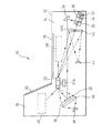
例えば、図27に示されるように、共通の光源1を使用するためには、ハーフミラー2等の光分割手段を設け、光源1から出射される光線を第1の光線成分と第2の光線成分に分割し、分割された2つの光線成分を直接及びミラーを介して共通のポリゴンミラー3に導く。ポリゴンミラー3で反射した第1の光線成分Xをミラー群M1 を介して装置の底部の読み取り窓4から出射させ、ポリゴンミラーで反射した第2の光線成分Yをミラー群M2 を介して装置の正面の読み取り窓5から出射させるようにする。そして、装置の底部及び正面の読み取り窓4,5から出射した光線は、物体に当たって反射する。その反射光線を検出器6,7で検出することにより、バーコードを読むことができる。
【0006】
バーの間隔の狭いバーコードをより確実に読むためには、バーコードに当たる光線の幅をできるだけ絞ることが必要である。このために、光源1と光分割手段2との間にビーム成形手段8を配置し、装置の底部の読み取り窓から出射した光線のビーム径が該読み取り窓4上の所望の位置で最小ビーム径となり、且つ装置の正面の読み取り窓5から出射した光線のビーム径が該読み取り窓から所望の位置で最小ビーム径となるようにするのが好ましい。こうすれば、共通の光源1及び共通のポリゴンミラー3を使用して、第一及び第二の走査光でバーコードをより確実且つ簡単に読むことができるようになる。
【0007】
【発明が解決しようとする課題】
特にバーの間隔の狭いバーコードを読み取る場合には、レーザービームの径が細い方が望ましい。バーコード読取り装置には最適読取領域が設定され、バーコードを読取る際には物品をこの領域を通過させる。レーザービームの焦点(径が最も細点)は最適読取り領域の中心辺りに設定することが望ましい。複数の走査ビームによりバーコードを読取るタイプの装置の場合には、底部窓を通して出射される走査光の光源から読取り領域中心までの距離と、正面窓を通して出射される走査光の光源から読取り中心までの距離とが等しいことが望ましい。しかし、光学部品配置などに制限があり、両者の距離を等しくすることが困難であるため、第一の走査光と第二の走査光との双方の焦点位置を合せることが困難である。そのため、第一の走査光の焦点を読取り領域の中心に設定すると、第二の走査光の焦点は読取領域の中心から外れた位置に設定せざるを得ず、第二の走査光ではバーコードを読取れない場合もある。
【0008】
本発明の目的は、共通の光源から出射し且つ光光分割手段によって分割された2つの光線成分のビーム径をできるだけ小さくすることができる光走査装置を提供することである。
本発明の目的は、共通の光源と2つの読み取り窓を備え、それぞれの読み取り窓から出射した光線により感度よくバーコードの読み取りを行うことのできる光走査装置を提供することである。
【0009】
【課題を解決するための手段】
本発明による光走査装置は、本体と、該本体に設けられた第1の読み取り窓と、該第1の読み取り窓に対して角度をなして該本体に設けられた第2の読み取り窓と、光源と、該光源から出射される光線を第1の光路に沿って進む第1の光線成分と第2の光路に沿って進む第2の光線成分に分割する光分割手段と、該光分割手段で分割された該第1の光線成分及び該第2の光線成分をそれぞれに該第1の読み取り窓及び該第2の読み取り窓から出射させる光ガイド手段と、該第1の読み取り窓及び該第2の読み取り窓から出射して物体に当たって反射する光線を検出する少なくとも一つの検出器と、該光源と該光分割手段との間に配置された第1のビーム成形手段と、該第1の光路及び該第2の光路の一方に配置された第2のビーム成形手段とを備え、該光源と、該光分割手段と、該第1のビーム成形手段と、該第2のビーム成形手段とは、1つのユニットとして形成され、該第2のビーム成形手段は該第1のビーム成形手段よりも焦点距離の長い光学素子であることを特徴とするものである。
また、本発明による光源モジュールは、光源と、該光源の出射光を成形する第1のビーム成形手段と、該第1のビーム成形手段の出射光を第1の光路に沿って進む第1の光線成分と第2の光路に沿って進む第2の光線成分に分割する光分割手段と、一方の光路に配置された第2のビーム成形手段とを備え、該第2のビーム成形手段は該第1のビーム成形手段よりも焦点距離の長い光学素子であることを特徴とするものである。
【0011】
上記構成においては、光源から出射する光線は第1のビーム成形手段によって所望の位置で最小ビーム径となるように絞られる。ただし、光分割手段で分割された2つの光線成分のそれぞれの最小ビーム径の部分がそれぞれの所望の位置にならないことがある。そこで、第1のビーム成形手段は、光分割手段で分割された2つの光線成分のうちの一方の光線成分について、最小ビーム径の部分がそれの所望の位置にくるように設定される。第2のビーム成形手段は、他方の光線成分の光路に配置され、その光路を通る光線の最小ビーム径の部分の位置を補正し、最小ビーム径の部分がそれの所望の位置にくるようにする。このようにして、光分割手段で分割された2つの光線成分について、それぞれの最小ビーム径の部分がそれぞれの所望の位置になるようにすることができる。
【0012】
上記構成とともに、下記の構成を採用することができる。
該光ガイド手段は、該光分割手段で分割された該第1の光線成分及び該第2の光線成分をそれぞれに反射させるポリゴンミラーと、該光分割手段と該ポリゴンミラーとの間に配置される少なくとも1つのミラーと、該ポリゴンミラーで反射した該第1の光線成分を該第1の読み取り窓から出射させる第1のミラー群と、該ポリゴンミラーで反射した該第2の光線成分を該第2の読み取り窓から出射させる第2のミラー群とからなる。
【0013】
該第1のビーム成形手段は該光源から出射される光線が該光源から第1の距離で最小ビーム径を有するようにビーム成形を行い、該第2のビーム成形手段は該一方の光路を通る光線成分が該第1の距離とは異なった該光源からの第2の距離で最小ビーム径を有するようにビーム成形を行う。
該第1のビーム成形手段はコリメータレンズとアパチャとを含む。
【0014】
該第2のビーム成形手段は該コリメータレンズよりも焦点距離が長い凸レンズからなる。あるいは、該第2のビーム成形手段は凹レンズからなる。あるいは、該第2のビーム成形手段は凹面鏡からなる。
該光源と、該光分割手段と、該第1のビーム成形手段とは、1つのユニットとして形成されている。
【0015】
該光源と、該光分割手段と、該第1のビーム成形手段と、該第2のビーム成形手段とは、1つのユニットとして形成されている。
【0016】
【発明の実施の形態】
図1及び図2は本発明の実施例によりバーコードリーダとして構成された光走査装置10を示す図である。光走査装置10は本体12を有し、本体12はベース部分14とカバー部分16とからなる。
ボトム読み取り窓18がベース部分14の表面に設けられ、サイド読み取り窓20がカバー部分16の表面に設けられる。ボトム読み取り窓18とサイド読み取り窓20とはほぼL字形をなすように互いに角度をなして配置される。
【0017】
図2においては、ボトム読み取り窓18から出射する光線の一つが矢印Xで示され、サイド読み取り窓20から出射する光線の一つが矢印Yで示される。ボトム読み取り窓18の上にあって、サイド読み取り窓20から所定の距離にある点を中心とする空間領域が最適の読み取り領域Pとなる。つまり、物体が最適の読み取り領域Pにあるとバーコードを最適に読み取ることができる。ただし、物体が最適の読み取り領域Pの外側に領域にあってもバーコードを読み取ることができるが、バー間隔が狭いので、バーコードの読取りは保証されない。
【0018】
図2において、光走査装置10は、光源(レーザーダイオード等)22と、第1のビーム成形手段24と、光分割部材26と、第2のビーム成形手段28とを含む。これらの部材は共通のフレームに取り付けられ、光源モジュール30としてユニット化されている。光走査装置10は、さらに、モータ32aによって回転させられるポリゴンミラー32と、2つのミラー34、36とを含む。光源モジュール30はベース部分14の一端部の低い位置に配置される。ミラー34はベース部分14の一端部の光源モジュール30の上に配置され、ミラー36はベース部分14の他端部に配置される。光源モジュール30は本体12内の図2で右端部に配置され、ポリゴンミラー32は本体12内の左端部近くで、2つの読み取り窓18,20の間に配置される。
【0019】
光分割部材26はハーフミラー、ハーフキューブ、あるいは偏光ビームスプリッタにより構成され、光源22から出射される光線を第1の光路に沿って進む第1の光線成分L1と第2の光路に沿って進む第2の光線成分L2に分割する。この場合、第1の光線成分L1は光分割部材26を透過して光分割部材26から真っ直ぐにポリゴンミラー32の一側へ向かい、第2の光線成分L2は光分割部材26で反射してミラー34、36でさらに反射して光路を曲げられてからポリゴンミラー32の他側へ向かう。第2の光線成分L2はミラー34、36間においてポリゴンミラー32の下側を通る。
【0020】
ポリゴンミラー32で図2で右側へ反射した第1の光線成分L1はボトムミラー群38を経て、例えば光線Xとしてボトム読み取り窓18から出射し、物体を走査する。ポリゴンミラー32で図2で左側へ反射した第2の光線成分L2はサイドミラー群40を経て、例えば光線Yとしてサイド読み取り窓20から出射し、物体を走査する。ボトムミラー群38及びサイドミラー群40は後で説明するようにそれぞれ複数のミラーを含み、それぞれ複数の光線で物体を走査する。
【0021】
最適の読み取り領域P(あるいはそのまわりの領域)に物体があると、光線X又は光線Yはその物体に当たって反射し、散乱し、この反射光は走査光が光源22から進んで来たときとは逆の進路を辿って戻る。物体で反射され、ボトム読み取り窓18を通ってポリゴンミラー32で反射された光線がL3で示されている。物体で反射され、サイド読み取り窓20を通ってポリゴンミラー32で反射された光線がL4で示されている。
【0022】
反射光を検出するために、第1の光線成分L1の光路には、光源モジュール30の近くに反射鏡42が配置される。反射鏡42はその中心部に穴42aを有する凹面鏡として形成される。穴42aは、光分割部材26からポリゴンミラー32へ向かう第1の光線成分L1を通過させる。反射鏡42の焦点の位置に第1の検出器44が配置される。反射光線L3は反射鏡42の広い面積に当たって反射され、且つ集光されて第1の検出器44に入射する。第1の検出器44はピンフォトダイオードからなり、検出した光量を電気信号に変換する。電気信号は図示しない電気回路に送られ、復調などの処理がほどこされる。これによって、物体に添付されたバーコードがあれば、バーコードを読み取ることができる。
【0023】
第2の光線成分L2の光路にあるミラー36の裏側には、ミラー36よりも大きな集光子46が配置される。集光子46は凸レンズ又はフレネルレンズによって形成されている。集光子46で集光された反射光線L4を検出するために第2の検出器48が集光子46の焦点の位置に配置される。反射光線L4は集光子46を通って第2の検出器48へ進む。第2の検出器48はピンフォトダイオードからなり、検出した光量を電気信号に変換する。電気信号は図示しない電気回路に送られる。よって、物体に添付されたバーコードがあれば、バーコードを読み取ることができる。
【0024】
図3は第1のビーム成形手段24の例を示している。第1のビーム成形手段24はコリメータレンズ50とアパチャ52とからなり、これらはモジュールとしてユニット化される。コリメータレンズ50は光源(レーザー光源)22から出射している発散性の光線を集光し、平行光よりもわずかに絞り、アパチャ52はコリメータレンズ50を通った光線の余分な光をカットして、ビーム径をさらに絞る。アパチャ52から出射した光線の径は次第に細くなり、最小ビーム径の部分Sを経た後で次第に太くなる。
【0025】
図4は第1のビーム成形手段24を通った光線のビーム径と光源22からの距離との関係を示す図である。距離a、b、c、dは図2の位置A、B、C、Dに対応している。すなわち、距離aは光源22からボトム読み取り窓18上の位置Aまでの距離、距離bは光源22からボトム読み取り窓18を通って最適読み取り領域Pの上の位置Bまでの距離である。また、距離cは光源22からサイド読み取り窓20上の位置Cまでの距離、距離dは光源22からサイド読み取り窓20を通って最適読み取り領域Pを越えた位置Dまでの距離である。
【0026】
図4において、ボトム読み取り領域Eはボトム読み取り窓18から出射する光線によって読み取り可能な領域であり、サイド読み取り領域Fはサイド読み取り窓20から出射する光線によって読み取り可能な領域である。最適読み取り領域Pはボトム読み取り領域E及びサイド読み取り領域Fよりもそれぞれ狭い。PB点は図2でAB方向の最適読み取り領域Pの中心までの距離に相当する点、PS点は図2でCD方向の最適読み取り領域Pの中心までの距離に相当する点である。
【0027】
図4から分かるように、光源22から点PBまでの距離は、光源22から点PSまでの距離よりも短い。このような場合、従来は、光線Xの最小ビーム径の部分SがPB点に位置するように設定していた。すると、光線Yの最小ビーム径になる位置はPS点からはずれてしまい、PS点におけるビーム径は最小ビーム径よりも少し大きくなってしまう。
【0028】
しかし、特にバーコードを構成するバーのピッチがさらに小さくなると、もっと小さいビーム径の光線で走査を行うことが望まれる。このために、第2のビーム成形手段28を設け、さらに光線Yのビーム径を細くして、望ましくはPS点付近で最小ビーム径となるようにする。
図5は第1のビーム成形手段24及び第2のビーム成形手段28の特徴を示す図である。曲線Gは図4の特性と同じである。曲線Hは、PS点におけるビーム径を小さくするために、第1のビーム成形手段24の設定を変えた場合を示す。これによって、曲線G上のPS点のビーム径は、曲線H上のPS′点のビーム径になる。つまり、サイド読み取り窓20から出射する光線YのPS点でのビーム径が小さくなる。図5においては、c−d間においては曲線Hの方が曲線Gよりも全体的にビーム径をしぼることができる。a−b間においては、特に読み取り窓に近い位置では、曲線Iの方が曲線H,Gよりもビーム径をしぼることができる。こうして、読み取り領域全般にわたってビーム径を小さくすることができるようになり、いずれの光線を使用してもよりバー幅が狭い細いバーコードを読み取ることができるようになる。
【0029】
曲線Gから曲線Hへの変更は、第1のビーム成形手段24の設定を変えることにより行われる。例えば、曲線Gから曲線Hへの変更は、ビームの焦点の位置、つまり光源22からの最小ビーム径の部分Sまでの距離を長くなるようにすることであり、これは第1のビーム成形手段24のコリメータレンズ50の焦点距離fを図4の場合よりも長さを長くすることによって達成される。例えば、曲線Gの特性はコリメータレンズ50の焦点距離fが3.6mmで達成されたとした場合、曲線Hの特性はコリメータレンズ50の焦点距離fが14mmで達成される。また、曲線Gの特性から曲線Hの特性への変更は、アパチャ52の穴の大きさを変えたり、光源22とコリメータレンズ50の間の距離を変えたりすることによっても達成される。
【0030】
しかし、曲線G上のPB点は、曲線H上のPB′点に移動し、ボトム読み取り窓18から出射する光線のビーム径はPB′点では大きくなる。そこで、第1の光線成分L1の光路に配置された第2のビーム成形手段28により、ボトム読み取り窓18から出射する光線Xについてのみ、ビーム成形を行う。つまり、ボトム読み取り窓18から出射する光線Xについては、焦点を結ぶ位置を曲線Hの特性から曲線Iの特性へ変更し、曲線H上のPB′点におけるビーム径を曲線I上のPB″点におけるビーム径へと小さくする。第2のビーム成形手段はビームスプリッタの後段に配置される。この場合、第2のビーム成形手段28の平凸レンズの焦点距離fは3000mmである。従って、コリメータレンズ50の焦点距離fが14mmであるのに対して、光線YのPS点でのビーム径を絞るための第2のビーム成形手段28の平凸レンズの方がコリメータレンズ50よりも数100倍も長い焦点距離をもつものである。
【0031】
これによって、サイド読み取り窓20から出射する光線のビーム径、及びボトム読み取り窓18から出射する光線のビーム径をともに小さくすることができ、小さなビーム径の光線で走査を行うことができる。実施例のモジュールでは、コリメータレンズで光線Yの焦点を最適読取り位置に合わせる。平凸レンズで、コリメータレンズにより合わせられてしまう光線Xの焦点を若干手前にもってくるようにする。
【0032】
図6は第1のビーム成形手段24の変形例を示す図である。この例においては、第1のビーム成形手段24はコリメータレンズ50とアパチャ52との間に配置された直角プリズム54をさらに含む。図7に示されるように、レーザーダイオード22から出射する光線は一般的に、直交する第1及び第2の光線成分のうち、一方の光線の発散角が他方の光線の発散角よりも大きくなる。直角プリズム54はそのような大きい発散角をもつ光線を絞って、他方の発散角の小さい方の光線の発散角と同等にするものである(ビーム径を成形する)。例えば,図6では、直角プリズム54は、発散角の大きい縦方向の光線を絞り、横方向の光線は絞らない。なお、図6では直角プリズム54の斜辺がアパチャ52側を向いて配置されているが、直角プリズム54の斜辺が光源22側を向いて配置されることもできる。また、直角プリズム54の代わりに直角ではないプリズムとすることもできる。
【0033】
図8は直角プリズム54の代わりにシリンドリカル凸レンズ54aとシリンドリカル凹レンズ54bを設けた例を示す図である。この場合には、実線で示す発散角の大きい縦方向の光線を点線で示す発散角の小さい横方向の光線の発散角と同等にすることができる。
図9は同様にシリンドリカル凹レンズ54cとシリンドリカル凸レンズ54dを設けた例を示す図である。この場合には、実線で示す発散角の小さい横方向の光線を点線で示す発散角の大きい縦方向の光線の発散角と同等にすることができる。
【0034】
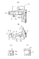
図26(A),(B)は直角プリズムを含む光源モジュール30を示す図であり、(A)は平面図、(B)は略垂直断面図である。光源モジュール30はボディ30aを含み、ボディ30aに光源22が取付けられている。光源モジュール30のボディ30a内には、第1のビーム成形手段24のコリメータレンズ50と、直角プリズム54と、第1のビーム成形手段24のアパチャ52と、光分割手段(ハーフミラー)26と、第2のビーム成形手段28とが配置されている。コリメータレンズ50は(D)に示されるようにアルミブロック50aに取りつけてボディ30aの一端側の穴に挿入され、第2のビーム成形手段28であるレンズはボディ30aの他端側の取りつけ溝28aに挿入される。第2のビーム成形手段28であるレンズはほぼ半円形状をしており、取りつけ穴28aは同レンズの外形と一致し、U字形の断面の溝である。
【0035】
図10及び図11は図2のボトムミラー群38の配置の一例を示す図である。図10及び図11は図2とは左右関係が逆に示されるいる。ボトムミラー群38は図2ではベース部分14のボトム読み取り窓18の直ぐ下にあるように示されているが、実際には、ボトムミラー群38のミラーはベース部分14の下方位置にも配置される。ボトムミラー群38のミラーはベース部分14の周辺位置に配置される。
【0036】
図10は図2のベース部分14が下方フレーム14aと上方フレーム14bとからなることを示している。図11はベース部分14の下方フレーム14aのみを示している。上方フレーム14bは図11の下方フレーム14aの左方部分上には取り付けられ、図2のカバー部分16は図11の右方部分上に取り付けられる。
【0037】
図10の下方フレーム14aの中央にはポリゴンミラー32が示されている。図11の下方フレーム14aの中央には支持台32bが示され、ポリゴンミラー32(図示せず)はこの支持台32bに取り付けられる。さらに、図11の左端部には図2の光分割部材26で反射した光線を受けるミラー34が示されており、図2の光源モジュール30はこのミラー34の下方に配置される。図11の右端部にはミラー34で反射した光線を受けるミラー36が示されており、図2の集光子46がフレネルレンズとしてこのミラー36の後方に示されている。集光子46で集光された反射光を受ける第2の検知器48はプリント基板56に取り付けられている。第1の検知器44も図11の左端底部のVゾーンに配置されたプリント基板(図示せず)に取り付けられる。
【0038】
図10及び図11に示されるように、下方フレーム14aはミラーZB2、VBRR、VBLL、HBR2、HBL2、ZML2、ZMR2を備えている。これらのミラーはボトムミラー群38の一部を構成する。下方フレーム14aはさらにミラーVSR1、VSL1を備えている。図10には、カバー16に取り付けられるミラーZL、ZRも示されている。これらのミラーはサイドミラー群40の一部を構成する。これらのミラーは概ね反射面を斜め上に向けて配置されている。
【0039】
上方フレーム14bはミラーZBR1、ZBL1、HBR1、HBL1、VBR1、VBL1、VBR2、VBL2、ZMR1、ZMR2を備えている。これらのミラーはボトムミラー群38の一部を構成する。これらのミラーは概ね反射面を斜め下に向けて配置されている。
ボトムミラー群38については、光源22から出射し、光分割部材26を透過し、ポリゴンミラー32で反射した光線は、上方フレーム14bのミラーに入射する。ポリゴンミラー32が時計方向に回転するときには、走査の順番は、ミラーZMR1、VBR2、VBR1、HBR1、ZBR1、ZBL1、HBL1、VBL2、VBL2、ZML1となる。上方フレーム14bのミラーで反射された光線は下方フレーム14aのミラーへ向かう。例えば、ミラーZMR1で反射された光線はミラーZMR2によって上向きに反射され、ボトム読み取り窓18から出射する。VBR2及びVBR1で反射された光線はミラーVBRRによって上向きに反射され、ボトム読み取り窓18から出射する。同様に、次のミラーによって反射された光線は他のミラーによって上向きに反射され、ボトム読み取り窓18から出射する。
【0040】
その結果、図12に示されるように、ボトム読み取り窓18から種々の方向及び角度の光線が出射し、物体を走査する。図2の矢印Xはこれらの光線の一つを代表的に示している。物体に当たった光線は上記したようにして第1の検出器44で検出される。
また、図13及び図14に示されるように、カバー部分16はミラーホルダ17を含み、ミラーホルダ17にはミラーVSL2、ZLL、ZHL、ZHR、ZRR、VSR2が取り付けられている。これらのミラーは上記ミラーVSR1、VSL1、ZL、ZRとともにサイドミラー群40を構成する。
【0041】
サイドミラー群40については、光源22から出射し、光分割部材26で反射した光線は、ミラー34及びミラー36で反射してポリゴンミラー32へ向かい、ポリゴンミラー32で反射した光線は下方フレーム14aのミラーVSR1、VSL1、ZL、ZRへ入射する。走査の順序は、VSL1、ZL、ZR、VSR1である。これらのミラーで反射した光線はミラーホルダ17のミラーへ向かって進み、ミラーホルダ17のミラーで反射してサイド読み取り窓20から出射する。
【0042】
従って、図15に示されるように、サイド読み取り窓20から種々の方向及び角度の光線が出射し、物体を走査する。図2の矢印Yはこれらの光線の一つを代表的に示している。物体に当たった反射光線は上記したようにして第2の検出器48で検出される。なお、図13では、集光子46と第2の検知器48との間にさらにミラー47が配置され、集光子46を通った光線がミラー47で反射して第2の検知器48に入射するようになっている。
【0043】
従って、物体のバーコードが上を向いていない限り、物体のバーコードがどの方向を向いていたとしても、ボトム読み取り窓18から出射した光線及びサイド読み取り窓20から出射した光線によりほとんどのバーコードを読み取ることができる。
図16は本発明の他の実施例を示す図である。この実施例は、第2のビーム成形手段28が前の実施例とは異なった位置に配置されている点を除くと、前の実施例と基本的に類似の構成を有する。この実施例では、第2のビーム成形手段28は、反射鏡42の穴42aに挿入された平凸レンズとして形成されている。つまり、反射鏡42の穴42aは、光分割部材26からポリゴンミラー32へ向かう第1の光線成分を通過させるとともに、そこに設けられた第2のビーム成形手段28は光線のビーム成形を行う機能をもっている。反射鏡42の穴42aの第2のビーム成形手段28は図2のものと同様の平凸レンズによって形成されることができる。従って、この実施例の作用は前の実施例の作用と同様である。図17(A)は反射鏡42を示す斜視図である。
【0044】
図17(B)はこの反射鏡42の変形例を示す平面図である。反射鏡42の穴42aには同心円状のパターンを有する透過型ホログラムが設けられている。このような透過型ホログラムは透過する光線に対して集光作用があるので、平凸レンズと同様に第2のビーム成形手段28として機能する。従って、この例の作用は前の実施例の作用と同様である。平凸レンズ及び/又はホログラムは凹面鏡と一体的に成形されてもよく、また凹面鏡とは別個に成形してはめこむようにしてもよい。
【0045】
図18は反射鏡42の変形例を示す図である。この例では、反射鏡42は平面鏡として形成されるが、同心円状のパターンを有する反射型ホログラムとして形成されており、ポリゴンミラー32から来た光線を集光させつつ第1の検知器44(図2)へ向かって反射させる。反射鏡42の穴42aには同心円状のパターンを有する透過型ホログラムが設けられている。従って、この例でも、前の例と同様の作用が得られる。
【0046】
図19は本発明の他の実施例を示す図である。この実施例は、第2のビーム成形手段28が前の実施例とは異なった位置に配置されている点を除くと、前の実施例と基本的に類似の構成を有する。この実施例では、第2のビーム成形手段28は、光源22から出射し、光分割部材26で反射した光線をポリゴンミラー32に向かって反射させるミラー34、36の間に配置された凹レンズ29として形成される。
【0047】
図20は図19の実施例について第1のビーム成形手段24及び第2のビーム成形手段28の作用を示す図である。図5の例と同様に、曲線Gは図4の特性と同じである。曲線Jは、PB点におけるビーム径を小さくするために、第1のビーム成形手段24の設定を変えた場合を示す。曲線Gの特性から曲線Hの特性への変更は第1のビーム成形手段24の設定を変えることにより光源22からの最小ビーム径の部分Sまでの距離を短くなるようにすることであり、これは第1のビーム成形手段24のコリメータレンズ50の焦点距離fの長さを短くすることによって達成される。また、曲線Gの特性から曲線Jの特性への変更は、アパチャ52の穴の大きさを変えたり、光源22とコリメータレンズ50の間の距離を変えたりすることによっても達成される。
その結果、曲線G上のPS点は、曲線J上のPS′点に移動し、PS点における光線のビーム径が大きくなる。そこで、第2のビーム成形手段28としての凹レンズ29により、曲線Jの特性から曲線Kの特性へ変更し、曲線J上のPS′点におけるビーム径を曲線K上のPS″点におけるビーム径へと小さくする。凹レンズ29は光源22から出射する光線の最小ビーム径の部分Sを遠ざけるような作用を有する。これによって、図2の実施例と同様な作用が得られる。
【0048】
図21は本発明の他の実施例を示す図である。この実施例では、第2のビーム成形手段28が前の実施例とは異なった位置に配置されている点を除くと、前の実施例と基本的に類似の構成を有する。この実施例では、第2のビーム成形手段28は、光源22から出射し、光分割部材26で反射した光線をミラー36へ向かって反射させるミラー34として形成される。このミラー36は凹面鏡として形成される。これによって、図19の実施例と同様な作用が得られる。
【0049】
図22は図21と類似した実施例を示す図である。この実施例では、第2のビーム成形手段28は、光源22から出射し、光分割部材26で反射した光線をミラー34を介してポリゴンミラー32へ反射させるミラー36として形成される。このミラー36は凹面鏡として形成される。これによって、図19の実施例と同様な作用が得られる。
【0050】
図23は図21及び図22と類似した実施例を示す図である。この実施例では、第2のビーム成形手段28は、ミラー34、36の一方が凹面鏡として形成されたものからなる。そして、ミラー34、36の他方はシリンドリカルレンズとして形成され、図8及び図9を参照して説明したようにレーザー光源22から出射する発散角の異なる光線のうちの一方の光線の発散角を制御するようになっている。
【0051】
図24は図2と類似した実施例を示す図である。この実施例では、第2のビーム成形手段28は、光分割部材26とミラー34との間に配置された平凸レンズ33として形成される。この平凸レンズ33の作用は図2の第2のビーム成形手段28としての平凸レンズの作用と同じである。この実施例は、図2の実施例とは逆に、光源22からボトム読み取り領域Eまでの距離が、光源22からサイド読み取り領域Eまでの距離よりも長い場合に有効である。
36の他方はシリンドリカルレンズとして形成され、図8及び図9を参照して説明したようにレーザー光源22から出射する発散角の異なる光線のうちの一方の光線の発散角を制御するようになっている。
【0052】
図25はさらに他の実施例を示す図である。上記の実施例は光走査装置がボトム読み取り窓18及びサイド読み取り窓20を有し、これらの読み取り窓に対して共通の光源22を使用していた。図25の実施例においては、光走査装置10は単一の読み取り窓180を有し、共通の光源22から出射する光線を光分割部材26によって2つの光線成分に分割し、2つの光線成分を読み取り窓180から出射させて、物体を走査するようになっている。第1のビーム成形手段24が光源22と光分割部材26との間に配置され、第2のビーム成形手段28が光分割部材26で分割された光線成分の一方の光路に配置される。第1のビーム成形手段24及び第2のビーム成形手段28の作用は上記の実施例のものと同様である。
【0053】
【発明の効果】
以上説明したように、本発明によれば、共通の光源から出射し且つ光分割手段によって分割された2つの光線成分のビーム径を小さくすることができる。
【図面の簡単な説明】
【図1】本発明の光走査装置を示す斜視図である。
【図2】本発明の実施例の光走査装置の内部構成を示す略断面図である。
【図3】図2の第1のビーム成形手段を示す拡大図である。
【図4】第1のビーム成形手段を通った光線のビーム径と光源からの距離との関係を示す図である。
【図5】図2の第1のビーム成形手段及び第2のビーム成形手段を用いてビーム成形を行うことを説明する図である。
【図6】第1のビーム成形手段の変形例を示す図である。
【図7】光源の出射光が縦方向と横方向で発散角が異なることを示す図である。
【図8】第1のビーム成形手段の変形例を示す図である。
【図9】第1のビーム成形手段の変形例を示す図である。
【図10】ボトムミラー群のミラーを示すための光走査装置の本体の下方フレーム及び上方フレームを示す分解図である。
【図11】図7の下方フレームを示す拡大図である。
【図12】ボトム読み取り窓から出射する光線を示す図である。
【図13】サイドミラー群のミラーを示すための光走査装置の本体の下方フレーム及びカバーを示す部分断面図である。
【図14】カバー内に配置されるミラーフレームに取り付けられたミラーを示す斜視図である。
【図15】サイド読み取り窓から出射する光線を示す図である。
【図16】本発明の他の実施例の光走査装置の内部構成を示す略断面図である。
【図17】図16の第2のビーム成形手段を含む反射鏡を示す図である。
【図18】図17の反射鏡の変形例を示す図である。
【図19】本発明の他の実施例の光走査装置の内部構成を示す略断面図である。
【図20】図19の第1のビーム成形手段及び第2のビーム成形手段を用いてビーム成形を行うことを説明する図である。
【図21】本発明の他の実施例の光走査装置の内部構成を示す略断面図である。
【図22】本発明の他の実施例の光走査装置の内部構成を示す略断面図である。
【図23】本発明の他の実施例の光走査装置の内部構成を示す略断面図である。
【図24】本発明の他の実施例の光走査装置の内部構成を示す略断面図である。
【図25】本発明の他の実施例の光走査装置を示す略図である。
【図26】光源モジュールを示す図である。
【図27】従来技術を示す図である。
【符号の説明】
10…光走査装置
12…本体
18…ボトム読み取り窓
20…サイド読み取り窓
22…光源
24…第1のビーム成形手段
26…光分割部材
28…第2のビーム成形手段
32…ポリゴンミラー
34、36…ミラー
38…ボトムミラー群
40…サイドミラー群
42…反射鏡
44、48…検出器
46…集光子
50…コリメータレンズ
52…アパチャ[0001]
TECHNICAL FIELD OF THE INVENTION
The present invention relates to an optical scanning device known as, for example, a bar code reader and a light source module used therein.
[0002]
[Prior art]
POS systems, which irradiate a light beam and detect a light beam reflected on an object to read a bar code attached to a product, are rapidly spreading. In this POS system, the operator can perform the checkout operation only by operating the product, so that the load on the operator is reduced.
[0003]
In recent years, an optical scanning device having two reading windows has been proposed. For example, two L-shaped reading windows are provided at the bottom and the front of the optical scanning device, and light beams can be emitted from both the reading windows to read a bar code of a product. In such an optical scanning device, the barcode can be read even if the barcode of the product is not oriented in a certain direction, so that the load on the operator can be further reduced.
[0004]
In an optical scanning device having a reading window at the bottom of the device and a reading window at the front of the device, an optical scanning system for a reading window at the bottom of the device and an optical scanning system for a reading window at the front of the device are provided. is necessary. Each optical scanning system includes a light source, scanning means such as a polygon mirror, and other mirrors. Therefore, the device becomes complicated, the number of parts increases, and the manufacturing cost of the optical scanning device having two reading windows increases. Therefore, if a common light source is used for the two optical scanning systems, the number of components is reduced, and the cost can be reduced.
[0005]
For example, as shown in FIG. 27, in order to use a
[0006]
In order to more reliably read a bar code having a narrow bar interval, it is necessary to reduce the width of a light beam hitting the bar code as much as possible. For this purpose, a beam shaping means 8 is arranged between the
[0007]
[Problems to be solved by the invention]
In particular, when reading a bar code having a narrow bar interval, it is desirable that the diameter of the laser beam be small. An optimum reading area is set in the bar code reader, and when reading a bar code, an article is passed through this area. It is desirable that the focal point (the point having the smallest diameter) of the laser beam be set near the center of the optimal reading area. In the case of an apparatus of a type that reads a barcode with a plurality of scanning beams, the distance from the light source of the scanning light emitted through the bottom window to the center of the reading area, and the distance from the light source of the scanning light emitted through the front window to the reading center. Are preferably equal to each other. However, there is a limit in the arrangement of optical components and the like, and it is difficult to equalize the distance between the two components. Therefore, it is difficult to match the focal positions of both the first scanning light and the second scanning light. Therefore, if the focus of the first scanning light is set at the center of the reading area, the focus of the second scanning light must be set at a position deviated from the center of the reading area. May not be read.
[0008]
SUMMARY OF THE INVENTION It is an object of the present invention to provide an optical scanning device capable of reducing the beam diameter of two light components emitted from a common light source and divided by a light beam dividing unit as much as possible.
SUMMARY OF THE INVENTION It is an object of the present invention to provide an optical scanning device having a common light source and two reading windows, and capable of reading a barcode with high sensitivity by light beams emitted from the respective reading windows.
[0009]
[Means for Solving the Problems]
An optical scanning device according to the present invention includes a main body, a first reading window provided in the main body, a second reading window provided in the main body at an angle with respect to the first reading window, A light source; light splitting means for splitting a light beam emitted from the light source into a first light ray component traveling along a first optical path and a second light ray component traveling along a second optical path; Light guide means for emitting the first light beam component and the second light beam component divided by the first reading window and the second reading window, respectively, the first reading window and the second At least one detector for detecting a light beam emitted from the second reading window and reflected on the object, a first beam shaping means arranged between the light source and the light splitting means, and the first optical path. And second beam shaping means disposed on one of the second optical paths; Comprising a light source, a light splitting means, and the first beam shaping means and the second beam shaping means are formed as one unitThe second beam shaping means is an optical element having a longer focal length than the first beam shaping means.It is characterized by the following.
Further, the light source module according to the present invention includes a light source, a first beam shaping unit for shaping the light emitted from the light source, and a first beam shaping unit that advances the light emitted from the first beam shaping unit along a first optical path. A light beam splitting means for splitting the light beam component into a second light beam component traveling along the second light path; and a second beam shaping means disposed on one of the light paths, wherein the second beam shaping means is The optical element has a longer focal length than the first beam shaping means.
[0011]
In the above configuration, the light beam emitted from the light source is narrowed by the first beam shaping means so as to have a minimum beam diameter at a desired position. However, the portions of the minimum beam diameters of the two light beam components split by the light splitting unit may not be at the respective desired positions. Therefore, the first beam shaping unit is set so that the minimum beam diameter portion of one of the two light beam components split by the light splitting unit comes to a desired position. The second beam shaping means is arranged in the optical path of the other light beam component, corrects the position of the minimum beam diameter portion of the light beam passing through the optical path, and moves the minimum beam diameter portion to its desired position. I do. In this way, for the two light beam components split by the light splitting means, the respective portions having the minimum beam diameters can be set at the respective desired positions.
[0012]
In addition to the above configuration, the following configuration can be adopted.
The light guide means is disposed between the light splitting means and the polygon mirror, and a polygon mirror for reflecting the first light beam component and the second light beam component split by the light splitting means, respectively. At least one mirror, a first mirror group that emits the first light beam component reflected by the polygon mirror from the first reading window, and a second mirror component that reflects the second light beam component reflected by the polygon mirror. And a second group of mirrors emitted from the second reading window.
[0013]
The first beam shaping means performs beam shaping such that a light beam emitted from the light source has a minimum beam diameter at a first distance from the light source, and the second beam shaping means passes through the one optical path. Beam shaping is performed such that the ray component has a minimum beam diameter at a second distance from the light source that is different from the first distance.
The first beam shaping means includes a collimator lens and an aperture.
[0014]
The second beam shaping means comprises a convex lens having a longer focal length than the collimator lens. Alternatively, the second beam shaping means comprises a concave lens. Alternatively, the second beam shaping means comprises a concave mirror.
The light source, the light splitting means, and the first beam shaping means are formed as one unit.
[0015]
The light source, the light splitting means, the first beam shaping means, and the second beam shaping means are formed as one unit.
[0016]
BEST MODE FOR CARRYING OUT THE INVENTION
1 and 2 are views showing an
A
[0017]
In FIG. 2, one of the light beams emitted from the
[0018]
2, the
[0019]
The
[0020]
The first light ray component L1 reflected to the right in FIG. 2 by the
[0021]
If there is an object in the optimal reading area P (or an area around it), the light beam X or the light beam Y is reflected and scattered upon the object, and this reflected light is different from when the scanning light travels from the
[0022]
In order to detect the reflected light, a reflecting
[0023]
On the back side of the
[0024]
FIG. 3 shows an example of the first
[0025]
FIG. 4 is a diagram showing the relationship between the beam diameter of the light beam passing through the first beam shaping means 24 and the distance from the
[0026]
In FIG. 4, a bottom reading area E is an area that can be read by a light beam emitted from the
[0027]
As can be seen from FIG. 4, the distance from the
[0028]
However, particularly when the pitch of the bars constituting the bar code is further reduced, it is desired to perform scanning with a light beam having a smaller beam diameter. For this purpose, the second beam shaping means 28 is provided, and the beam diameter of the light ray Y is further reduced so that the minimum beam diameter is preferably obtained near the PS point.
FIG. 5 is a diagram showing characteristics of the first
[0029]
The change from the curve G to the curve H is performed by changing the setting of the first
[0030]
However, the point PB on the curve G moves to the point PB 'on the curve H, and the beam diameter of the light beam emitted from the
[0031]
Thus, the beam diameter of the light beam emitted from the
[0032]
FIG. 6 is a view showing a modification of the first
[0033]
FIG. 8 is a diagram showing an example in which a cylindrical
FIG. 9 is a view showing an example in which a cylindrical concave lens 54c and a cylindrical
[0034]
FIGS. 26A and 26B are views showing the
[0035]
10 and 11 are views showing an example of the arrangement of the
[0036]
FIG. 10 shows that the
[0037]
A
[0038]
As shown in FIGS. 10 and 11, the
[0039]
The
With respect to the
[0040]
As a result, as shown in FIG. 12, light beams of various directions and angles are emitted from the
As shown in FIGS. 13 and 14, the
[0041]
With respect to the
[0042]
Accordingly, as shown in FIG. 15, light beams of various directions and angles are emitted from the
[0043]
Therefore, as long as the bar code of the object is not facing up, the light emitted from the
FIG. 16 is a diagram showing another embodiment of the present invention. This embodiment has a configuration basically similar to that of the previous embodiment except that the second beam shaping means 28 is arranged at a different position from the previous embodiment. In this embodiment, the second beam shaping means 28 is formed as a plano-convex lens inserted into the
[0044]
FIG. 17B is a plan view showing a modification of the reflecting
[0045]
FIG. 18 is a view showing a modified example of the reflecting
[0046]
FIG. 19 is a diagram showing another embodiment of the present invention. This embodiment has a configuration basically similar to that of the previous embodiment except that the second beam shaping means 28 is arranged at a different position from the previous embodiment. In this embodiment, the second beam shaping means 28 serves as a concave lens 29 disposed between
[0047]
FIG. 20 is a diagram showing the operation of the first beam shaping means 24 and the second beam shaping means 28 for the embodiment of FIG. Similar to the example of FIG. 5, the curve G is the same as the characteristic of FIG. A curve J indicates a case where the setting of the first
As a result, the PS point on the curve G moves to the PS ′ point on the curve J, and the beam diameter of the light beam at the PS point increases. Therefore, the concave lens 29 as the second beam shaping means 28 changes the characteristic of the curve J to the characteristic of the curve K, and changes the beam diameter at the point PS ′ on the curve J to the beam diameter at the point PS ″ on the curve K. The concave lens 29 has an effect of keeping the minimum beam diameter portion S of the light beam emitted from the
[0048]
FIG. 21 is a diagram showing another embodiment of the present invention. This embodiment has a configuration basically similar to that of the previous embodiment except that the second beam shaping means 28 is arranged at a different position from that of the previous embodiment. In this embodiment, the second beam shaping means 28 is formed as a
[0049]
FIG. 22 shows an embodiment similar to FIG. In this embodiment, the second
[0050]
FIG. 23 is a diagram showing an embodiment similar to FIGS. 21 and 22. In this embodiment, the second beam shaping means 28 comprises one of the
[0051]
FIG. 24 shows an embodiment similar to FIG. In this embodiment, the second beam shaping means 28 is formed as a plano-
The other of 36 is formed as a cylindrical lens, and controls the divergence angle of one of the light beams having different divergence angles emitted from the
[0052]
FIG. 25 is a diagram showing still another embodiment. In the above embodiment, the optical scanning device has the
[0053]
【The invention's effect】
As described above, according to the present invention, the beam diameter of two light components emitted from a common light source and split by the light splitting unit can be reduced.
[Brief description of the drawings]
FIG. 1 is a perspective view showing an optical scanning device of the present invention.
FIG. 2 is a schematic sectional view showing an internal configuration of the optical scanning device according to the embodiment of the present invention.
FIG. 3 is an enlarged view showing a first beam forming means of FIG. 2;
FIG. 4 is a diagram showing a relationship between a beam diameter of a light beam passing through a first beam shaping unit and a distance from a light source.
FIG. 5 is a diagram illustrating that beam shaping is performed using the first beam shaping unit and the second beam shaping unit of FIG. 2;
FIG. 6 is a view showing a modification of the first beam forming means.
FIG. 7 is a diagram showing that light emitted from a light source has different divergence angles in a vertical direction and a horizontal direction.
FIG. 8 is a diagram showing a modification of the first beam shaping means.
FIG. 9 is a view showing a modification of the first beam forming means.
FIG. 10 is an exploded view showing a lower frame and an upper frame of the main body of the optical scanning device for showing mirrors of a bottom mirror group.
FIG. 11 is an enlarged view showing the lower frame of FIG. 7;
FIG. 12 is a diagram illustrating light rays emitted from a bottom reading window.
FIG. 13 is a partial sectional view showing a lower frame and a cover of a main body of the optical scanning device for showing mirrors of a side mirror group;
FIG. 14 is a perspective view showing a mirror attached to a mirror frame arranged in a cover.
FIG. 15 is a diagram showing light rays emitted from a side reading window.
FIG. 16 is a schematic sectional view showing the internal configuration of an optical scanning device according to another embodiment of the present invention.
FIG. 17 is a diagram showing a reflecting mirror including the second beam shaping means of FIG. 16;
FIG. 18 is a view showing a modification of the reflecting mirror of FIG. 17;
FIG. 19 is a schematic sectional view showing the internal configuration of an optical scanning device according to another embodiment of the present invention.
FIG. 20 is a diagram illustrating that beam shaping is performed using the first beam shaping unit and the second beam shaping unit of FIG. 19;
FIG. 21 is a schematic sectional view showing an internal configuration of an optical scanning device according to another embodiment of the present invention.
FIG. 22 is a schematic sectional view showing the internal configuration of an optical scanning device according to another embodiment of the present invention.
FIG. 23 is a schematic sectional view showing the internal configuration of an optical scanning device according to another embodiment of the present invention.
FIG. 24 is a schematic sectional view showing the internal configuration of an optical scanning device according to another embodiment of the present invention.
FIG. 25 is a schematic view showing an optical scanning device according to another embodiment of the present invention.
FIG. 26 is a diagram showing a light source module.
FIG. 27 is a diagram showing a conventional technique.
[Explanation of symbols]
10 ... Optical scanning device
12 ... body
18… Bottom reading window
20: Side reading window
22 ... light source
24 first beam shaping means
26 ... Light splitting member
28 second beam shaping means
32 ... Polygon mirror
34, 36 ... Mirror
38… Bottom mirror group
40 ... side mirror group
42 ... Reflector
44, 48 ... detector
46 ... condenser
50 ... Collimator lens
52 ... Aperture
Claims (2)
該本体に設けられた第1の読み取り窓と、
該第1の読み取り窓に対して角度をなして該本体に設けられた第2の読み取り窓と、
光源と、
該光源から出射される光線を第1の光路に沿って進む第1の光線成分と第2の光路に沿って進む第2の光線成分に分割する光分割手段と、
該光分割手段で分割された該第1の光線成分及び該第2の光線成分をそれぞれに該第1の読み取り窓及び該第2の読み取り窓から出射させる光ガイド手段と、該第1の読み取り窓及び該第2の読み取り窓から出射して物体に当たって反射する光線を検出する少なくとも一つの検出器と、
該光源と該光分割手段との間に配置された第1のビーム成形手段と、
該第1の光路及び該第2の光路の一方に配置された第2のビーム成形手段とを備え、該光源と、該光分割手段と、該第1のビーム成形手段と、該第2のビーム成形手段とは、1つのユニットとして形成され、該第2のビーム成形手段は該第1のビーム成形手段よりも焦点距離の長い光学素子である
ことを特徴とする光走査装置。Body and
A first reading window provided in the main body,
A second reading window provided in the main body at an angle to the first reading window;
A light source,
Light splitting means for splitting a light beam emitted from the light source into a first light beam component traveling along a first optical path and a second light beam component traveling along a second optical path;
A light guide unit for emitting the first light beam component and the second light beam component split by the light splitting unit from the first reading window and the second reading window, respectively, and the first reading unit A window and at least one detector for detecting light rays emitted from the second reading window and reflected on the object;
First beam shaping means disposed between the light source and the light splitting means;
A second beam shaping means disposed on one of the first optical path and the second optical path, the light source, the light splitting means, the first beam shaping means, and the second beam shaping means; The beam scanning unit is formed as one unit, and the second beam forming unit is an optical element having a longer focal length than the first beam forming unit. .
該光源の出射光を成形する第1のビーム成形手段と、
該第1のビーム成形手段の出射光を第1の光路に沿って進む第1の光線成分と第2の光路に沿って進む第2の光線成分に分割する光分割手段と、
一方の光路に配置された第2のビーム成形手段とを備え、該第2のビーム成形手段は該第1のビーム成形手段よりも焦点距離の長い光学素子であることを特徴とする光源モジュール。A light source,
First beam shaping means for shaping outgoing light of the light source;
A light dividing means which divides into a first light beam component and second beam component traveling along a second optical path traveling light emitted the first beam shaping means along the first optical path,
A light source module , comprising: a second beam shaping means disposed on one optical path , wherein the second beam shaping means is an optical element having a longer focal length than the first beam shaping means .
Priority Applications (6)
| Application Number | Priority Date | Filing Date | Title |
|---|---|---|---|
| JP20813797A JP3580676B2 (en) | 1997-08-01 | 1997-08-01 | Optical scanning device and light source module |
| US09/045,044 US6469294B2 (en) | 1997-08-01 | 1998-03-20 | Optical scanner and light source module with reduced light beam diameter |
| EP98303749A EP0895176B1 (en) | 1997-08-01 | 1998-05-13 | Optical scanner and light source module |
| KR10-1998-0017156A KR100444814B1 (en) | 1997-08-01 | 1998-05-13 | Optical scanning device and method and light source module |
| DE69834871T DE69834871T2 (en) | 1997-08-01 | 1998-05-13 | Optical scanner and light source module |
| CNB981084451A CN1162799C (en) | 1997-08-01 | 1998-05-15 | Optical scanner and light source module |
Applications Claiming Priority (1)
| Application Number | Priority Date | Filing Date | Title |
|---|---|---|---|
| JP20813797A JP3580676B2 (en) | 1997-08-01 | 1997-08-01 | Optical scanning device and light source module |
Publications (2)
| Publication Number | Publication Date |
|---|---|
| JPH1153460A JPH1153460A (en) | 1999-02-26 |
| JP3580676B2 true JP3580676B2 (en) | 2004-10-27 |
Family
ID=16551257
Family Applications (1)
| Application Number | Title | Priority Date | Filing Date |
|---|---|---|---|
| JP20813797A Expired - Fee Related JP3580676B2 (en) | 1997-08-01 | 1997-08-01 | Optical scanning device and light source module |
Country Status (6)
| Country | Link |
|---|---|
| US (1) | US6469294B2 (en) |
| EP (1) | EP0895176B1 (en) |
| JP (1) | JP3580676B2 (en) |
| KR (1) | KR100444814B1 (en) |
| CN (1) | CN1162799C (en) |
| DE (1) | DE69834871T2 (en) |
Families Citing this family (14)
| Publication number | Priority date | Publication date | Assignee | Title |
|---|---|---|---|---|
| US20030092023A1 (en) * | 1998-08-12 | 2003-05-15 | Daniel Dupret | Method of shuffling polynucleotides using templates |
| US6932271B2 (en) * | 2000-01-27 | 2005-08-23 | Ricoh Company, Ltd. | Optical scan module, optical scanner, optical scan method, image generator and image reader |
| US6899272B2 (en) * | 2000-05-17 | 2005-05-31 | Symbol Technologies, Inc | Bioptics bar code reader |
| DE60210010T2 (en) * | 2002-01-28 | 2006-10-12 | Fujifilm Electronic Imaging Ltd., Hemel Hempstead | Collimation system for laser diode |
| US7536271B2 (en) * | 2007-06-04 | 2009-05-19 | The Boeing Company | Methods and systems for manufacturing large components |
| US8740084B2 (en) * | 2009-11-12 | 2014-06-03 | Symbol Technologies, Inc. | Method and apparatus for projecting illumination patterns from barcode readers |
| US8496178B2 (en) * | 2011-08-31 | 2013-07-30 | Ncr Corporation | Method and apparatus for providing customer side imaging as well as bar code scanning imaging |
| US8757494B2 (en) * | 2011-09-27 | 2014-06-24 | Symbol Technologies, Inc. | Illumination system in imaging scanner |
| US9218516B2 (en) * | 2012-06-08 | 2015-12-22 | Datalogic ADC, Inc. | Data reader platter with integral features delineating a data-reading sweep region |
| USD723560S1 (en) * | 2013-07-03 | 2015-03-03 | Hand Held Products, Inc. | Scanner |
| CN103414834B (en) * | 2013-07-26 | 2016-01-20 | 深圳市顶星数码网络技术有限公司 | A kind of screen power-saving method, device and mobile terminal |
| USD730901S1 (en) * | 2014-06-24 | 2015-06-02 | Hand Held Products, Inc. | In-counter barcode scanner |
| CN105788108A (en) * | 2016-03-05 | 2016-07-20 | 福建联迪商用设备有限公司 | POS machine with function of scanning mirror two-dimensional code |
| US10802475B2 (en) * | 2018-07-16 | 2020-10-13 | Elite Robotics | Positioner for a robotic workcell |
Family Cites Families (8)
| Publication number | Priority date | Publication date | Assignee | Title |
|---|---|---|---|---|
| DE3935239A1 (en) * | 1988-10-21 | 1990-04-26 | Asahi Optical Co Ltd | SCANNER |
| US5206491A (en) * | 1990-03-02 | 1993-04-27 | Fujitsu Limited | Plural beam, plural window multi-direction bar code reading device |
| US5742038A (en) | 1990-09-28 | 1998-04-21 | Symbol Technologies, Inc. | Beam shaping for optical scanners |
| US5278397A (en) | 1991-07-25 | 1994-01-11 | Symbol Technologies, Inc. | Multi-resolution bar code reader |
| US5369284A (en) * | 1993-03-30 | 1994-11-29 | The Charles Stark Draper Laboratory, Inc. | Active edge position measuring device |
| CA2580492C (en) | 1995-03-17 | 2007-10-09 | Symbol Technologies, Inc. | Optical scanners having dual surface optical elements for dual working ranges |
| US5646391A (en) * | 1995-05-11 | 1997-07-08 | Psc, Inc. | Optical assembly for controlling beam size in bar code scanners |
| JP3441580B2 (en) | 1995-12-14 | 2003-09-02 | 富士通株式会社 | Reader |
-
1997
- 1997-08-01 JP JP20813797A patent/JP3580676B2/en not_active Expired - Fee Related
-
1998
- 1998-03-20 US US09/045,044 patent/US6469294B2/en not_active Expired - Lifetime
- 1998-05-13 KR KR10-1998-0017156A patent/KR100444814B1/en not_active IP Right Cessation
- 1998-05-13 DE DE69834871T patent/DE69834871T2/en not_active Expired - Lifetime
- 1998-05-13 EP EP98303749A patent/EP0895176B1/en not_active Expired - Lifetime
- 1998-05-15 CN CNB981084451A patent/CN1162799C/en not_active Expired - Fee Related
Also Published As
| Publication number | Publication date |
|---|---|
| JPH1153460A (en) | 1999-02-26 |
| KR100444814B1 (en) | 2004-11-16 |
| EP0895176A3 (en) | 2001-12-19 |
| DE69834871D1 (en) | 2006-07-27 |
| KR19990023129A (en) | 1999-03-25 |
| DE69834871T2 (en) | 2006-10-19 |
| US20010019104A1 (en) | 2001-09-06 |
| EP0895176A2 (en) | 1999-02-03 |
| EP0895176B1 (en) | 2006-06-14 |
| CN1162799C (en) | 2004-08-18 |
| CN1207538A (en) | 1999-02-10 |
| US6469294B2 (en) | 2002-10-22 |
Similar Documents
| Publication | Publication Date | Title |
|---|---|---|
| USRE40102E1 (en) | Electro-optical scanner having stationary, multi-surface mirror having surfaces with aplanar profiles | |
| JP3580676B2 (en) | Optical scanning device and light source module | |
| US5859417A (en) | Optical scanners having dual surface optical elements for dual working ranges | |
| USRE40101E1 (en) | Electro-optical scanner having selectable scan pattern | |
| JPH0628508A (en) | Optical read method and optical reader | |
| EP0833273B1 (en) | Optical device | |
| EP0623889B1 (en) | Optical bar code scanner | |
| JPS6448017A (en) | Optical reader | |
| WO1997031340A1 (en) | Optical reflection sensing arrangement for scanning devices | |
| JPH03199929A (en) | Optical sensor | |
| JP2001256430A (en) | Scanner | |
| JPH079698A (en) | Multibeam light source | |
| JP3374028B2 (en) | Optical reader | |
| JP2531890Y2 (en) | Optical sensor | |
| JPH02101595A (en) | Bar-code scanner | |
| JP3866321B2 (en) | Optical scanner | |
| JP2825108B2 (en) | Barcode information reader | |
| JPH06103392A (en) | Bar-code reader | |
| JP3578602B2 (en) | Document detection device | |
| JPH03129583A (en) | Bar code reader | |
| JPH11110474A (en) | Bar code reading device | |
| JPH04330583A (en) | Bar code reader | |
| JPH04211882A (en) | Information reader | |
| JPH02244289A (en) | Multi-beam type bar code reader | |
| JPH01306812A (en) | Laser light scanning and photodetecting device |
Legal Events
| Date | Code | Title | Description |
|---|---|---|---|
| A02 | Decision of refusal |
Free format text: JAPANESE INTERMEDIATE CODE: A02 Effective date: 20021210 |
|
| A61 | First payment of annual fees (during grant procedure) |
Free format text: JAPANESE INTERMEDIATE CODE: A61 Effective date: 20040720 |
|
| R150 | Certificate of patent or registration of utility model |
Free format text: JAPANESE INTERMEDIATE CODE: R150 |
|
| FPAY | Renewal fee payment (event date is renewal date of database) |
Free format text: PAYMENT UNTIL: 20080730 Year of fee payment: 4 |
|
| FPAY | Renewal fee payment (event date is renewal date of database) |
Free format text: PAYMENT UNTIL: 20090730 Year of fee payment: 5 |
|
| FPAY | Renewal fee payment (event date is renewal date of database) |
Free format text: PAYMENT UNTIL: 20100730 Year of fee payment: 6 |
|
| FPAY | Renewal fee payment (event date is renewal date of database) |
Free format text: PAYMENT UNTIL: 20100730 Year of fee payment: 6 |
|
| FPAY | Renewal fee payment (event date is renewal date of database) |
Free format text: PAYMENT UNTIL: 20110730 Year of fee payment: 7 |
|
| FPAY | Renewal fee payment (event date is renewal date of database) |
Free format text: PAYMENT UNTIL: 20110730 Year of fee payment: 7 |
|
| FPAY | Renewal fee payment (event date is renewal date of database) |
Free format text: PAYMENT UNTIL: 20120730 Year of fee payment: 8 |
|
| FPAY | Renewal fee payment (event date is renewal date of database) |
Free format text: PAYMENT UNTIL: 20120730 Year of fee payment: 8 |
|
| FPAY | Renewal fee payment (event date is renewal date of database) |
Free format text: PAYMENT UNTIL: 20130730 Year of fee payment: 9 |
|
| LAPS | Cancellation because of no payment of annual fees |