JP3580560B2 - Elastic compression molding method and elastic compression mold - Google Patents
Elastic compression molding method and elastic compression mold Download PDFInfo
- Publication number
- JP3580560B2 JP3580560B2 JP14819792A JP14819792A JP3580560B2 JP 3580560 B2 JP3580560 B2 JP 3580560B2 JP 14819792 A JP14819792 A JP 14819792A JP 14819792 A JP14819792 A JP 14819792A JP 3580560 B2 JP3580560 B2 JP 3580560B2
- Authority
- JP
- Japan
- Prior art keywords
- mold
- cavity
- elastic compression
- molding
- molding material
- Prior art date
- Legal status (The legal status is an assumption and is not a legal conclusion. Google has not performed a legal analysis and makes no representation as to the accuracy of the status listed.)
- Expired - Fee Related
Links
Images


Classifications
-
- B—PERFORMING OPERATIONS; TRANSPORTING
- B29—WORKING OF PLASTICS; WORKING OF SUBSTANCES IN A PLASTIC STATE IN GENERAL
- B29C—SHAPING OR JOINING OF PLASTICS; SHAPING OF MATERIAL IN A PLASTIC STATE, NOT OTHERWISE PROVIDED FOR; AFTER-TREATMENT OF THE SHAPED PRODUCTS, e.g. REPAIRING
- B29C45/00—Injection moulding, i.e. forcing the required volume of moulding material through a nozzle into a closed mould; Apparatus therefor
- B29C45/17—Component parts, details or accessories; Auxiliary operations
- B29C45/46—Means for plasticising or homogenising the moulding material or forcing it into the mould
- B29C45/56—Means for plasticising or homogenising the moulding material or forcing it into the mould using mould parts movable during or after injection, e.g. injection-compression moulding
- B29C45/561—Injection-compression moulding
Description
【0001】
【産業上の利用分野】
本発明は肉厚の相違する成形品をひけなどの欠陥なく精密に射出成形するための方法とその方法を実施するための金型に関する。
【0002】
【従来の技術】
射出成形品は、一様に凝固して製品表面にひけなどの欠陥が発生しないようにするために総ての肉厚がほぼ等しくなるように予め設計される事が望ましい。しかしながら、例えばレンズのようにその製品の本質的な性質から、すべての部分において肉厚を等しくする事ができない場合がある。
【0003】
以下、従来例の問題点としてレンズ成形の場合を例にとって説明する。図3は普通成形と呼ばれる方法で、これによれば、凸面形状の金型キャビティ(20)に、レンズ(B)の周縁となる部分から成形材料(21)を射出し、そのまま凝固させてから取り出す方法である。この場合、ゲート入り口部分(22)の充填密度が密になり、ゲート(23)から離れるほど充填密度が粗となる。その結果、凝固した場合、ゲート近傍(22)より反対側(24)の方が収縮量が多くなり、レンズ面がゆがむという問題を発生させる。同時に、成形品(B)の中央部分が周縁部より肉厚であるから、周縁部より凝固が遅くなり、引けが発生して中央部分が更にゆがむという問題点がある。従って、このような普通成形によって作られるレンズ(B)は非常に低級なものに限られる事になる。凝固により変形したレンズ(B)の形状を2点鎖線(25)で示す。
【0004】
そこで、精密レンズの製造方法として図4に示すようなマイクロモルダ法が提案された。即ち、この方法によると、キャビティ部分を構成する部分金型(30a)(30b)を金型本体(31a)(31b)とは別個に用意しておき、キャビティ(32)への成形材料(33)の射出が完了するとキャビティ部分を構成する部分金型(30a)を稼働させて油圧圧縮し、凝固させるという方法である。
【0005】
この方法によれば、成形品(33)全体を加圧しつつ凝固させるのであるから、前記普通成形に比べてひずみは小さくなるが、尚、問題をはらんでいる。即ち、成形品(33)が周縁部(34)と中央部分(35)とでは肉厚が相違する。従って、周縁部(34)の方が中央部分(35)より速く凝固する事になる。するとキャビティ部分(32)を構成する金型(30a)(30b)は凝固した周縁部(34)を圧縮する事になり、溶融状態にある中央部分(35)には加圧力が掛からない事になる。
【0006】
その結果、中央部分(35)にひけが発生し、中央部分(35)のレンズ面に微妙なひずみが発生し、十分な精度が得られない事になる。しかも、中央部分(35)には加圧力が加わらないので周縁部(34)より充填密度が低くなり、周縁部(34)と中央部分(35)とで光の屈折率が微妙に相違するようになるという問題も残る。
【0007】
【発明が解決しようとする課題】
本発明は、かかる従来例の欠点に鑑みてなされたもので、キャビティ内の成形材料が総ての部分において凝固するまで、均等に加圧力を掛け続ける事が出来る弾性圧縮成形方法と前記方法を実施するための金型の提供をその目的とする。
【0008】
【課題を解決するための手段】
上記課題を解決するための方法は請求項1に示すように、『固定金型 (4) 及び可動金型 (2) のキャビティ (7) の背面側にそれぞれ空隙 (10) を設けてキャビティ (7) を構成する部分がいずれも弾性変形可能に構成された金型キャビティ (7) に成形材料を射出し、その射出圧によりキャビティ内容積が拡大する方向に固定金型 (4) 及び可動金型 (2) を弾性変形させ、金型キャビティ (7) 内の成形材料全面に弾性圧縮力を作用させつつ凝固させる事』を特徴とする。
これにより、成形品全体の凝固が完了するまで成形品全体に均等な圧力が加わる事になり、極めて精密な成形を行う事ができる。
【0009】
請求項2は、前記方法を実施するための弾性金型で、『固定金型 (4) 及び可動金型 (2) のキャビティ (7) を構成する部分が弾性変形可能な厚さに形成されている事』を特徴とする。これにより、金型キャビティ内に射出された成形材料によって固定金型 (4) 及び可動金型 (2) のキャビティ部分が弾性変形してキャビティ内容積が拡張され、この弾性変形による弾性力が全体の凝固が完了するまで金型キャビティ内の成形材料全面ににほぼ均等に掛かり、全体にわたって均質でひずみの少ない成形品を形成する事ができる。
【0010】
請求項3は、弾性金型の1実施例で、『固定金型 (4) 及び可動金型 (2) のキャビティ (7) の背面側にそれぞれ空隙 (10) を設けることによって、弾性変形可能な厚さに形成されている事』を特徴とする。金型キャビティの背後に空隙を設けることによってキャビティ部分の金型部分が弾性変形するようにしたものである。
【0011】
【実施例】
以下、本発明を図示実施例に従って詳述する。符号(1)は可動ダイプレートで、この進行方向面の所定位置には可動金型(2)が着脱可能に取り付けられている。(3)は固定ダイプレートで、この内側面には固定金型(4)が前記可動金型(2)に圧締される位置に着脱可能に取り付けられけている。そして上記可動ダイプレート(1)と固定ダイプレート(3)とは4本のタイバー(5)によって支持されており、可動ダイプレート(1)は適宜手段{本実施例ではトグル機構(6)}によって固定ダイプレート(3)に対して圧接・離間するようにスライド可能に支持されている。
【0012】
可動・固定両金型(2)(4)のパーティング面には例えば凸レンズ形成用のキャビティ(7)が凹設されている。(11)は前記キャビティ(7)に連通するゲートであり、(12)はスプルである。
【0013】
可動・固定両金型(2)(4)の金型キャビティ(7)を構成する金型部分(9)の背面が凹設されていて、凸レンズ形成の場合には、キャビティ(7)の中央に近付くに連れて次第に薄くなるように設定されている。前記可動・固定両金型(2)(4)を可動ダイプレート(1)や固定ダイプレート(3)に取り付けた場合、キャビティ(7)の背面に空隙(10)が形成される事になる。そして、この空隙(10){又は凹所}により金型キャビティ(7)を構成する金型部分(9)は成形に材料(8)の射出圧入により弾性変形可能になる。
【0014】
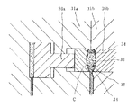
凹所(10)の形状はレンズ形成の場合には円形の窪みとなるが、図2の破線で示すようにコーナ部(13)に丸味を設けてもよい。又、凹所(10)の大きさはキャビティ(7)より大きくしても良いし、小さくしても良い。要するに、凹所(10)の直径や金型キャビティ(7)を構成する金型部分(9)の厚み、凹所(10)の直径、コーナ部(13)の大きさ又は有無などは成形されるレンズ(8)のレンズ面の曲率半径、直径、材質並びに金型(2)(4)側の物理的性質(線膨張率、引張り強さ、熱伝導率、ヤング率、ポアソン比など)などによって最適の寸法が選定される。
【0015】
しかして、トグル機構(6)を作動させて可動金型(2)を固定金型(4)に圧締し、続いて、成形材料(8)である溶融樹脂をキャビティ(7)内に射出する。キャビティ(7)内に射出された成形材料(8)は図2に示すように射出圧(=樹脂圧)によって金型キャビティ(7)を構成する金型部分(9)を弾性変形によって拡張する。換言すればキャビティ(7)内の成形材料(8)は前記金型部分(9)によって全面にわたって均等に締め付けられている事になる。
【0016】
射出が完了すると保圧工程にはいるが、この段階でキャビティ(7)内の成形材料(8)はガスを放出しつつ冷却して次第に凝固・収縮して行く。この場合、ゲート(11)や周縁部(14)などの薄肉部分から凝固が始まり、次第に厚肉の中央部(15)にと凝固していく。
【0017】
この時、前記金型部分(9)の全体が弾性変形しているので、周縁部(14)が凝固しても周縁部(14)に独立して非凝固部分に付いては弾性的圧力をかけ続けて行く事ができ、成形品(A)の形状を最終的形状に矯正して行く事ができる。即ち、成形材料(8)の冷却過程でガスが抜け、収縮し、樹脂圧が低下するに連れてキャビティ(7)は元の形状に復帰して行く事になる。これにより、成形品(A)は射出から凝固完了まで、その全面にわたって均等な締め付け力を受ける事になり、レンズ面の精度は勿論、全体に均質な状態となり、極めて高品質のレンズが簡単且つ大量に製作できる事になる。
【0018】
成形品(A)が凝固すると、トグル機構(6)を折り畳み方向に作動させて型開きし、成形品(A)の取り出しを行い、次の射出成形作業に備える。
【0019】
尚、本発明ではレンズ成形を例にとって説明したが、勿論、これに限られるものでなく、肉厚に不同がある射出成形に対して広く適用する事ができるものであるさことは言うまでもない。即ち、凝固の遅い部分の金型部分の肉厚を薄くして弾性変形可能にし、凝固の遅い部分に対しても独立して適正な弾性的圧縮力を掛けつつ凝固させて『ひけ』などの欠陥が表面に現れないようにするだけでなく、キャビティ形状に正確に沿った成形品を得る事も出来る。
【0020】
【効果】
本発明方法は、金型キャビティに成形材料を射出して金型キャビティを拡大方向に弾性変形させ、金型キャビティ内の成形材料全面に弾性力を作用させつつ凝固させるので、薄肉部が凝固しても凝固部分に独立して非凝固部分に付いて弾性的圧力をかけ続けて行く事ができ、成形品の形状をキャビティ形状にあった最終的形状に矯正して行く事ができるという利点がある。
【0021】
又、請求項2の弾性圧縮成形金型は、金型キャビティを構成する金型部分が弾性変形可能な厚さに形成されているので、成形材料の射出後、冷却過程でガスが抜けると共に収縮し、樹脂圧が低下するに連れてキャビティは元の形状に復帰して行く事になり、これにより、成形品は射出から凝固完了まで、その全面にわたって均等な締め付け力を受ける事になって成形品の精度は勿論、全体に均質な状態となり、極めて高品質の成形品が簡単且つ大量に製作できる事になる。
【図面の簡単な説明】
【図1】本発明の射出成形装置の金型及びトグル機構部分の1実施例の断面図
【図2】本発明に係る弾性圧縮成形金型の一実施例の断面図
【図3】従来の普通成形のキャビティ部分の断面図
【図4】従来のマイクロモルダ法によるレンズ成形の金型部分の断面図
【図5】図4のキャビティ部分の拡大断面図
【符号の説明】
(1)…可動ダイプレート (2)…可動金型
(3)…固定ダイプレート (4)…固定金型
(5)…タイバー (6)…トグル機構
(7)…金型キャビティ (8)…成形材料
(A)…成形品 (9)…キャビティを構成する金型部分
(10)…空隙 (11)…ゲート
(12)…ランナ (13)…コーナー部
(14)…周縁部 (15)…中央部[0001]
[Industrial applications]
The present invention relates to a method for precisely injection-molding molded articles having different thicknesses without defects such as sink marks, and a mold for performing the method.
[0002]
[Prior art]
It is desirable that the injection-molded product is designed in advance so that all the thicknesses are substantially equal in order to prevent solidification evenly and defects such as sink marks on the product surface. However, there are cases where the wall thickness cannot be made equal in all parts due to the essential properties of the product such as a lens.
[0003]
Hereinafter, as a problem of the conventional example, a case of lens molding will be described. FIG. 3 shows a method generally called molding. According to this method, a molding material (21) is injected into a convex-shaped mold cavity (20) from a portion to be a periphery of a lens (B), and solidified as it is. It is a method of taking out. In this case, the filling density of the gate entrance portion (22) becomes dense, and the filling density becomes coarser as the distance from the gate (23) increases. As a result, when solidified, the amount of shrinkage is greater on the opposite side (24) than near the gate (22), causing the problem that the lens surface is distorted. At the same time, since the central part of the molded article (B) is thicker than the peripheral part, there is a problem that solidification is slower than the peripheral part, shrinkage occurs, and the central part is further distorted. Therefore, the lens (B) made by such ordinary molding is limited to a very low-grade lens. The shape of the lens (B) deformed by solidification is indicated by a two-dot chain line (25).
[0004]
Therefore, a micromolding method as shown in FIG. 4 has been proposed as a method of manufacturing a precision lens. That is, according to this method, the partial molds (30a) (30b) constituting the cavity are prepared separately from the mold bodies (31a) (31b), and the molding material (33) for the cavity (32) is prepared. ) Is completed, the partial mold (30a) constituting the cavity is operated to hydraulically compress and solidify.
[0005]
According to this method, since the entire molded article (33) is solidified while applying pressure, the strain is smaller than that of the ordinary molding, but there is still a problem. That is, the thickness of the molded article (33) is different between the peripheral portion (34) and the central portion (35). Therefore, the peripheral portion (34) solidifies faster than the central portion (35). Then, the molds (30a) and (30b) constituting the cavity portion (32) compress the solidified peripheral portion (34), and the pressing force is not applied to the central portion (35) in the molten state. Become.
[0006]
As a result, sink marks occur in the central portion (35), and slight distortion occurs on the lens surface of the central portion (35), and sufficient accuracy cannot be obtained. Moreover, since no pressing force is applied to the central portion (35), the packing density is lower than that of the peripheral portion (34), and the refractive index of light is slightly different between the peripheral portion (34) and the central portion (35). Problem remains.
[0007]
[Problems to be solved by the invention]
The present invention has been made in view of the above-mentioned drawbacks of the conventional example, and is directed to an elastic compression molding method and an elastic compression molding method capable of continuously applying a pressing force until the molding material in the cavity solidifies in all portions. Its purpose is to provide a mold for performing.
[0008]
[Means for Solving the Problems]
A method for solving the above-mentioned problem is to provide a cavity (10) on the back side of a cavity (7) of a fixed mold (4) and a movable mold (2 ) by providing a cavity ( 10). The molding material is injected into a mold cavity (7) in which all parts constituting the mold (7) are configured to be elastically deformable, and the fixed mold (4) and the movable mold are moved in a direction in which the volume in the cavity is expanded by the injection pressure. The mold (2) is elastically deformed and solidified while applying an elastic compressive force to the entire surface of the molding material in the mold cavity (7) . "
As a result, uniform pressure is applied to the entire molded product until solidification of the entire molded product is completed, and extremely precise molding can be performed.
[0009]
[0010]
[0011]
【Example】
Hereinafter, the present invention will be described in detail with reference to the illustrated embodiments. Reference numeral (1) denotes a movable die plate, and a movable mold (2) is detachably attached to a predetermined position on the plane in the traveling direction. A fixed die plate (3) has a fixed mold (4) detachably mounted on the inner surface thereof at a position where the fixed mold (4) is pressed against the movable mold (2). The movable die plate (1) and the fixed die plate (3) are supported by four tie bars (5), and the movable die plate (1) is appropriately provided (toggle mechanism (6) in this embodiment). Thus, it is slidably supported so as to be pressed against and separated from the fixed die plate (3).
[0012]
For example, a cavity (7) for forming a convex lens is formed in the parting surface of both the movable and fixed molds (2) and (4). (11) is a gate communicating with the cavity (7), and (12) is a sprue.
[0013]
The back surface of the mold portion (9) constituting the mold cavity (7) of both the movable and fixed molds (2) and (4) is concave, and in the case of forming a convex lens, the center of the cavity (7) is formed. It is set so that it gradually becomes thinner as it approaches. When the movable and fixed dies (2) and (4) are attached to the movable die plate (1) and the fixed die plate (3), a gap (10) is formed on the back surface of the cavity (7). . Then, the mold portion (9) constituting the mold cavity (7) by the gap (10) {or the recess} can be elastically deformed by injection-pressing the material (8) into the molding.
[0014]
The shape of the recess (10) is a circular depression when a lens is formed, but the corner (13) may be rounded as shown by the broken line in FIG. Also, the size of the recess (10) may be larger or smaller than the cavity (7). In short, the diameter of the recess (10), the thickness of the mold portion (9) constituting the mold cavity (7), the diameter of the recess (10), the size of the corner portion (13), and the like are formed. Radius, diameter, material, and physical properties (linear expansion coefficient, tensile strength, thermal conductivity, Young's modulus, Poisson's ratio, etc.) of the lens (8) on the mold (2) (4) side The optimal dimensions are selected by
[0015]
Then, the movable mold (2) is pressed against the fixed mold (4) by operating the toggle mechanism (6), and subsequently, the molten resin as the molding material (8) is injected into the cavity (7). I do. The molding material (8) injected into the cavity (7) expands the mold portion (9) constituting the mold cavity (7) by elastic deformation by injection pressure (= resin pressure) as shown in FIG. . In other words, the molding material (8) in the cavity (7) is uniformly tightened over the entire surface by the mold portion (9).
[0016]
When the injection is completed, a pressure-holding step is started. At this stage, the molding material (8) in the cavity (7) cools while releasing gas, and gradually solidifies and contracts. In this case, solidification starts from a thin portion such as the gate (11) and the peripheral portion (14), and gradually solidifies into a thick central portion (15).
[0017]
At this time, since the entire mold portion (9) is elastically deformed, even if the peripheral portion (14) solidifies, the elastic pressure is applied to the non-solidified portion independently of the peripheral portion (14). The molding can be continuously performed, and the shape of the molded article (A) can be corrected to the final shape. That is, the gas escapes and shrinks in the process of cooling the molding material (8), and the cavity (7) returns to its original shape as the resin pressure decreases. As a result, the molded product (A) receives an even tightening force over the entire surface from injection to solidification, and the entire surface of the molded product (A) is homogeneous, as well as the accuracy of the lens surface. It can be produced in large quantities.
[0018]
When the molded product (A) solidifies, the toggle mechanism (6) is operated in the folding direction to open the mold, the molded product (A) is taken out, and is ready for the next injection molding operation.
[0019]
In the present invention, the lens molding has been described as an example. However, it is needless to say that the present invention is not limited to this, but can be widely applied to injection molding having uneven thickness. In other words, the thickness of the mold part in the part where solidification is slow is made thinner so that it can be elastically deformed. In addition to preventing defects from appearing on the surface, it is also possible to obtain a molded article that exactly conforms to the cavity shape.
[0020]
【effect】
According to the method of the present invention, the molding material is injected into the mold cavity to elastically deform the mold cavity in the enlargement direction and solidify while applying an elastic force to the entire surface of the molding material in the mold cavity. Even though the solidified part can be applied to the non-solidified part independently and elastic pressure can be applied continuously, the advantage that the shape of the molded product can be corrected to the final shape that was in the cavity shape is there.
[0021]
According to the second aspect of the present invention, since the mold portion constituting the mold cavity is formed to have a thickness capable of being elastically deformed, gas is released and contracted during the cooling process after injection of the molding material. Then, as the resin pressure decreases, the cavity returns to its original shape, and the molded product receives an even tightening force over its entire surface from injection to solidification. Of course, the precision of the product is of course uniform throughout, so that extremely high quality molded products can be manufactured easily and in large quantities.
[Brief description of the drawings]
FIG. 1 is a cross-sectional view of one embodiment of a mold and a toggle mechanism of an injection molding apparatus according to the present invention. FIG. 2 is a cross-sectional view of one embodiment of an elastic compression molding die according to the present invention. FIG. 4 is a cross-sectional view of a mold part for lens molding by a conventional micromolding method. FIG. 5 is an enlarged cross-sectional view of a cavity part of FIG.
(1) Movable die plate (2) Movable die (3) Fixed die plate (4) Fixed die (5) Tie bar (6) Toggle mechanism (7) Mold cavity (8) Molding material (A) Molded product (9) Mold part forming cavity (10) Void (11) Gate (12) Runner (13) Corner (14) Peripheral edge (15) Center
Claims (3)
Priority Applications (1)
| Application Number | Priority Date | Filing Date | Title |
|---|---|---|---|
| JP14819792A JP3580560B2 (en) | 1992-05-13 | 1992-05-13 | Elastic compression molding method and elastic compression mold |
Applications Claiming Priority (1)
| Application Number | Priority Date | Filing Date | Title |
|---|---|---|---|
| JP14819792A JP3580560B2 (en) | 1992-05-13 | 1992-05-13 | Elastic compression molding method and elastic compression mold |
Publications (2)
| Publication Number | Publication Date |
|---|---|
| JPH05309705A JPH05309705A (en) | 1993-11-22 |
| JP3580560B2 true JP3580560B2 (en) | 2004-10-27 |
Family
ID=15447434
Family Applications (1)
| Application Number | Title | Priority Date | Filing Date |
|---|---|---|---|
| JP14819792A Expired - Fee Related JP3580560B2 (en) | 1992-05-13 | 1992-05-13 | Elastic compression molding method and elastic compression mold |
Country Status (1)
| Country | Link |
|---|---|
| JP (1) | JP3580560B2 (en) |
Families Citing this family (2)
| Publication number | Priority date | Publication date | Assignee | Title |
|---|---|---|---|---|
| NL1031450C2 (en) * | 2006-03-27 | 2007-09-28 | Blankhorst Beheer B V | Injection molding tool for producing e.g. crates, contains mold cavity with flexible wall portion which can be deformed to increase or reduce cavity size |
| JP5740183B2 (en) * | 2011-03-15 | 2015-06-24 | ジヤトコ株式会社 | Mold for casting |
-
1992
- 1992-05-13 JP JP14819792A patent/JP3580560B2/en not_active Expired - Fee Related
Also Published As
| Publication number | Publication date |
|---|---|
| JPH05309705A (en) | 1993-11-22 |
Similar Documents
| Publication | Publication Date | Title |
|---|---|---|
| JPH0684031B2 (en) | Injection molding method | |
| JP3476841B2 (en) | Plastic lens injection molding method | |
| JP3580560B2 (en) | Elastic compression molding method and elastic compression mold | |
| JP3284114B2 (en) | Mold | |
| JP3131620B2 (en) | Injection compression molding method | |
| JP3350581B2 (en) | In-mold vibration processing method and apparatus | |
| JP2821093B2 (en) | Manufacturing method of plastic molded article and molding die | |
| JP2994580B2 (en) | Injection mold, injection molding apparatus, and injection molding method | |
| JPH08323816A (en) | Compression injection mold | |
| JP2001058335A (en) | Method and mold for molding plastic material | |
| JP3728119B2 (en) | Optical element mold and molding method | |
| JP3140486B2 (en) | Injection molding method for thick products | |
| JPH0788900A (en) | Molds | |
| JP2002187168A (en) | Mold for molding optical element and optical element molded article | |
| JPS615913A (en) | Mold assembly of discoid recording medium base | |
| JPH06182835A (en) | Injection mold | |
| JPH08142145A (en) | Injection mold and injection compression molding method using the same | |
| JPS5948735B2 (en) | Plastic lens molding correction method | |
| JP2957614B2 (en) | Plastic lens molding method and molding die | |
| JP3179139B2 (en) | Method for manufacturing resin molded products | |
| JP3088765B2 (en) | Injection mold and injection molding method using the mold | |
| JP2716333B2 (en) | Manufacturing method of plastic molded products | |
| JP3327799B2 (en) | Molding method and mold for long optical element | |
| JPH09174631A (en) | Injection molding method | |
| JPS63145010A (en) | Injection mold |
Legal Events
| Date | Code | Title | Description |
|---|---|---|---|
| A521 | Written amendment |
Free format text: JAPANESE INTERMEDIATE CODE: A523 Effective date: 20040604 |
|
| A61 | First payment of annual fees (during grant procedure) |
Effective date: 20040720 Free format text: JAPANESE INTERMEDIATE CODE: A61 |
|
| R150 | Certificate of patent (=grant) or registration of utility model |
Free format text: JAPANESE INTERMEDIATE CODE: R150 |
|
| FPAY | Renewal fee payment (prs date is renewal date of database) |
Free format text: PAYMENT UNTIL: 20090730 Year of fee payment: 5 |
|
| FPAY | Renewal fee payment (prs date is renewal date of database) |
Free format text: PAYMENT UNTIL: 20090730 Year of fee payment: 5 |
|
| FPAY | Renewal fee payment (prs date is renewal date of database) |
Year of fee payment: 6 Free format text: PAYMENT UNTIL: 20100730 |
|
| LAPS | Cancellation because of no payment of annual fees |