JP3578218B2 - Retaining bolster for piercing catheter - Google Patents
Retaining bolster for piercing catheter Download PDFInfo
- Publication number
- JP3578218B2 JP3578218B2 JP51630895A JP51630895A JP3578218B2 JP 3578218 B2 JP3578218 B2 JP 3578218B2 JP 51630895 A JP51630895 A JP 51630895A JP 51630895 A JP51630895 A JP 51630895A JP 3578218 B2 JP3578218 B2 JP 3578218B2
- Authority
- JP
- Japan
- Prior art keywords
- bolster
- catheter
- medical device
- tubular medical
- main body
- Prior art date
- Legal status (The legal status is an assumption and is not a legal conclusion. Google has not performed a legal analysis and makes no representation as to the accuracy of the status listed.)
- Expired - Fee Related
Links
Images


Classifications
-
- A—HUMAN NECESSITIES
- A61—MEDICAL OR VETERINARY SCIENCE; HYGIENE
- A61M—DEVICES FOR INTRODUCING MEDIA INTO, OR ONTO, THE BODY; DEVICES FOR TRANSDUCING BODY MEDIA OR FOR TAKING MEDIA FROM THE BODY; DEVICES FOR PRODUCING OR ENDING SLEEP OR STUPOR
- A61M25/00—Catheters; Hollow probes
- A61M25/01—Introducing, guiding, advancing, emplacing or holding catheters
- A61M25/02—Holding devices, e.g. on the body
- A61M2025/0213—Holding devices, e.g. on the body where the catheter is attached by means specifically adapted to a part of the human body
- A61M2025/0233—Holding devices, e.g. on the body where the catheter is attached by means specifically adapted to a part of the human body specifically adapted for attaching to a body wall by means which are on both sides of the wall, e.g. for attaching to an abdominal wall
Abstract
Description
発明の背景
本発明は医療装置に関し、特に、表皮表面に隣接して管状の医療装置を調整自在に支持するための保持ボルスタに関する。
典型的には、保持ボルスタは患者の人体に対してカテーテルを固定的に保持するためにカテーテルの出口箇所に位置する。カテーテルの支持を維持し、出口箇所におけるカテーテルの曲げ又はクリンプを阻止するために、ボルスタは適所に係止される。このように配置されたときに、ボルスタはカテーテルの出口箇所において患者の人体から皮膚へ圧力を継続的に直接作用させるが、この場合、時として、カテーテルの出口箇所で皮膚の治療を阻害してしまうことがあり、作用する圧力のために壊疽を発症する恐れがある。
カテーテルの如き管状の医療装置を人体の外部で支持するためのボルスタは患者に対する装置の固定的な係留を維持する際に使用していた。横方向の支持を提供するため、ボルスタは表皮に接触するフランジ、クロスバー又はディスクを使用していた。これらの支持体により加えられる継続的な直接圧力を最小化する従来の試みとして、例えばボルスタのクロスバーの下側にパッドやウエブを配置する方法が採用されてきた。しかし、パッド及びウエブは、実際には、特にカテーテルを偶発的又は意図的に出口箇所で動かしたときに、出口箇所において局部圧力を増大させてしまう傾向を有する。更に、刺通カテーテルの配置技術はごく普通の技術になってきているので、カテーテルは長期間にわたって使用されてきた。従って、カテーテルの出口箇所での皮膚の伝染もごく普通のこととなってきた。
現存のボルスタの欠陥を増大させる1つの特定の応用は胃内に長期間アクセスするために胃切開用の刺通カテーテル(PEGチューブ)を使用することである。PEGチューブは、胃内へのアクセスを提供するために使用されている間、保持ボルスタにより小穴の出口箇所で数カ月間保持される。しかし、使用中にカテーテルを適所に維持するために確固として保持される既存のボルスタは長期間の間にカテーテルの避けがたい運動に順応できない。カテーテルが動きまわると、偶発的に又は看護している医師や看護婦により取り扱われるときに、付加的な圧力が働いてボルスタを皮膚の表面内へ突っ込ませ、圧力による皮膚の炎症や小穴箇所の細化を生じさせてしまう。このような欠陥により、現存のボルスタは皮膚の刺激や伝染の原因となっていた。
それ故、管状の医療装置を支持するために表皮表面に隣接して使用する改善した保持ボルスタを提供する必要性がある。カテーテルの出口箇所で最少量の圧力を作用させた状態でカテーテルを適所に固定的に保持し、負傷を生じさせずに小穴の出口箇所のまわりでのカテーテルの運動を許容するこのようなボルスタは本出願人に係る米国特許出願第07/911,171号明細書(1992年7月9日付出願)に記載されている。
長期間の腸投薬に使用する大半のカテーテルは不活性で生化学的に矛盾を生じない医療等級のシリコンゴム又はポリウレタンから作られる。このようなカテーテルは柔軟で可撓性を有し、患者にとって心地よいものである。このようなカテーテルにおける1つの問題点は、カテーテルが直角に撓む地点でよじれを生じさせる傾向があることであり、これは、カテーテルを皮膚の表面上で下方へ押し込むときに頻繁に生じる。カテーテルがボルスタから出る地点でカテーテルを繰り返し撓ませると、その撓み地点で連続的な応力が発生し、カテーテルを弱化させると共に、応力破壊を発生させてカテーテルにひび割れを生じさせ、医療装置の早期破壊を起こさせる。これは、小児患者に使用する典型的には18Fr又はそれ以下の寸法の小径カテーテルにおいて特に顕著である。このような小径のカテーテルは一層薄い壁厚を有し、カテーテルの繰り返しの撓みに起因する早期破壊を一層起こし易い。
発明の概要
本発明は、表皮の表面に対して刺通カテーテル又はその他の類似の医療装置を固定的に安全に支持し、患者に負傷を生じさせずにカテーテルの出口個所のまわりでのカテーテルの運動を許容する保持ボルスタを提供する。保持ボルスタはカテーテルに固定的に取り付けるための手段と、患者の表皮表面に接触する凸状に湾曲した表面とを有する。ボルスタは、凸状湾曲表面が患者の表皮表面に接触した状態で、カテーテルに取り付けられ、カテーテル即ち管状医療装置の出口箇所での管状医療装置の運動に応じて凸状湾曲表面と表皮の表面との間の接触部分に沿って揺動する。従って、小穴の出口箇所での患者の負傷を生じさせることなく、小穴の出口箇所のまわりでの揺動運動が可能となる。カテーテル装置に対する横方向の圧力を解除したとき、ボルスタはその元の直立位置へ戻る。
上述のように刺通カテーテルの固定的な取り付けを提供するほかに、カテーテルが出口箇所から離れる方向へ屈曲したときのカテーテルのよじれを阻止する補助をなす2つの好ましい実施例を後に説明する。第1の好ましい実施例によれば、細長いカラーが撓むことのできるような弾力性を有し、よじれを生じさせずに出口箇所から離れるように横方向へカテーテルを屈曲できるようにする。ボルスタのカラー部分のまわりで着脱可能なプラスチック製の捩りロック(係止手段)を設けて、ボルスタをカテーテルに固定的に係止し、使用者がボルスタを調整してボルスタの下方の表面を洗浄するためにボルスタを一時的に緩めたい場合は、係止状態を容易に解除できる。
第2の好ましい実施例によれば、カテーテル内の湾曲した通路によりカテーテルのよじれが阻止され、この湾曲通路は、カテーテルを位置決めし、皮膚の表面に実質上平行な(カテーテルの)側出口の方へカテーテルを指向させる。側出口ボルスタはスリットにより取り付けを容易にし、このスリットは、カテーテル上でのボルスタの前進運動及び引き続きの枢動運動を容易にする。
従って、本発明の目的は、カテーテルが小穴箇所から離れるように横方向に撓んだときにカテーテルのよじれを阻止する揺動可能な保持ボルスタを提供することである。
別の目的は、カテーテルの繰り返しの位置決めの後のカテーテルの早期ひび割れ即ち破壊を阻止することである。
更に別の目的は、カテーテルに対するボルスタの係止及び係止解除を行う便利で簡単な手段を提供することである。
他の目的は、必要なら、ボルスタの調整及び再位置決めを容易に行えるようにすることである。
本発明の別の目的は、小穴の出口箇所から離れるような横方向の所定の角度でカテーテルを固定保持する揺動可能な保持ボルスタを提供することである。
別の目的は、皮膚の表面に対して実質上平行にカテーテルを保持して、カテーテルによる長期の投薬を受ける小児患者にとって特に有用な揺動可能な保持ボルスタを提供することである。
本発明の更に別の目的は、カテーテルのまわりで容易に前進させることができ、カテーテル上で容易に位置決めできるボルスタを提供することである。
これら目的及びその他の目的、並びに、利点は、以下の説明から明らかとなろう。
【図面の簡単な説明】
第1図は、小穴箇所で薄壁カテーテルに装着された上記米国特許出願第07/911,171号明細書に記載された如き揺動可能な保持ボルスタの側立面図で、ボルスタから離れるようにある角度で撓んでよじれたカテーテルを示す図、
第2図は、小穴箇所で薄壁カテーテルに装着された細長い可撓性のカラーを備えた修正した保持ボルスタの側立面図で、よじれを生じずにボルスタから離れるようにある角度で撓みボルスタの可撓性カラーにより支持されたカテーテルを示す図、
第3図は、小穴箇所のまわりで薄壁カテーテルに取り付けられた第2図のボルスタの側断面図で、撓んでいない状態のカテーテル及びボルスタを示す図、
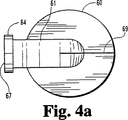
第4aー4d図は側出口保持ボルスタを示す図で、第4a図は側出口保持ボルスタの上面図、第4b図は斜視図、第4c図は側断面図、第4d図は端立面図、
第5図は、薄壁カテーテルに沿って装着位置へ前進せしめられた状態の第4aー4d図の側出口保持ボルスタの斜視図、
第6図は、カテーテルに沿って装着位置へ前進せしめられカテーテルのまわりで枢動できる状態を示す第4−5図の側出口保持ボルスタの側立面図、
第7図は、小穴箇所でカテーテルを保持するために適所に枢動され薄壁カテーテルに装着された状態を示す第4−6図の揺動可能な保持ボルスタの側立面図、及び
第8a図は開状態を示すプラスチック製の捩りロックの上面図、第8b図は閉状態を示す第8a図のプラスチック製の捩りロックの上面図である。
好ましい実施例の説明
本発明の原理の理解を促進するため、特定の用語を用いて図示の実施例を説明するが、このような実施例は本発明を限定するものではなく、種々の変形、修正及び本発明の原理の更なる応用が可能であることは言うまでもない。
第1図を参照すると、保持ボルスタ10は胃33の壁32に接触する拡大先端部30を有する胃切開用の刺通カテーテル28と共働する。カテーテル28は保持ボルスタ10と拡大先端部30との間の圧縮作用により表皮層34を挟んでクランプされる。図示のように、拡大先端部30はこの拡大先端部と表皮層との間にシールを提供し、早急な治癒を保証するために胃壁32に均一な圧力を作用させる。同様に、保持ボルスタ10は圧縮作用を維持するのに必要な同じ値で反対向きの圧力を小穴の出口箇所36において作用させる。
第1図に示すように、保持ボルスタ10は円筒状の部分12の近くに位置する調整可能なクランプ38を有する。クランプ38はボア16内でカテーテル28をクランプしシールするために円筒状部分12に対する締め付けを調整する。従って、保持ボルスタ10は表皮表面40に接触する適所に保持される。第1図に示す方位においては、カテーテル28は、カテーテルの運動に応答して凸状表面18及び表皮表面40に沿って小穴の出口箇所のまわりで揺動した状態で示されている。例えば、カテーテルを介して胃内へ栄養性液体を導入するようにカテーテルを位置決めすることによりカテーテルに外力が作用すると、保持ボルスタ10が揺動し、表皮表面40上の圧力を減少させると共に、表皮表面上の力作用点を移動させる。保持ボルスタと拡大先端部との間の圧縮作用の中心点が出口箇所から離れるように移動するため、外力を解除した後にカテーテルをセンタリングさせるようなオーバーターン運動即ち裏返し運動が生じる。従って、保持ボルスタ10は自動的なセンタリング能力を有する。更に、カテーテル28をその元の位置へ戻すような自動的なセンタリング作用により、保持ボルスタ10は胃壁32内への拡大先端部30の内方移動量を最小限に抑えるように作用する。
第1図は小穴箇所36で薄壁カテーテル28に装着された上記米国特許出願第07/911,171号明細書に記載された如き保持ボルスタ10を示し、カテーテル28は小穴箇所36から離れるように撓んでよじれている。この例においては、ボルスタ10の円筒状部分12は約0.100インチ(約2.54mm)の壁厚と、約3/8インチ(約9.53mm)の高さとを有する。比較的大きな高さ及び壁厚のため、円筒状部分12は薄壁カテーテル28より一層剛直となる。従って、カテーテル28が第1図に示すように撓んだとき、カテーテル28は地点15でよじれる傾向がある。この傾向は以下に説明する本発明の2つの新規な実施例により排除できる。
第2図は修正したボルスタ50を示し、このボルスタは小穴箇所36で薄壁カテーテル28に装着された細長い可撓性カラー51を有する。第2図において、カテーテル28は、細長い可撓性のカラー51により提供される撓み支持のためよじれを生じることなく、小穴箇所36から離れるように横方向に撓んだ状態で示されている。可撓性のカラー51は比較的肉薄(約0.03インチ即ち約0.76mm)で、細長く(約3/4インチ即ち19.1mmの高さ)、従って、カラーは撓み中のカテーテルのための撓み支持体として作用し、カテーテルのよじれを防止する。つまり、カラー51はカテーテル28のよじれ即ち応力による早期のひび割れを回避する歪み取り手段としての機能を果たす。従って、カテーテル28が小穴箇所36から離れるように横方向に撓んだとき、ボルスタ50の凸状に湾曲した下面接触部分58が揺動し、可撓性のカラー51が屈曲して、撓み中のカテーテル28上に歪みが発生するのを防止する。この簡単で機能的な構成により、ボルスタの揺動作用を阻害することなく、また、コストを増大させることなく、優れた効果が得られる。
ボルスタ50は着脱可能なプラスチック製の捩りロック(係止手段)80によりカテーテル28上の適所に固定的に保持され、この捩りロックはカラー51の近傍に位置し、カテーテル28に把持圧力を作用させる。環状フランジ53、54はカラー51上の適所に捩りロック80を保持する機能を果たす。使用者がボルスタを調整してボルスタの下方の表面を洗浄するためにボルスタを一時的に緩めたい場合は、捩りロック80の係止状態を容易に解除できる。
ボルスタ50は約50のショアA硬さの医療等級の弾性シリコン、又は、モンサント社(Monsanto)のSANTOPRENE(登録商標名)或いはシェルケミカル社(Shell Chemical)のKRATON(登録商標名)の如き合成ゴムから一部品としてモールド成形され、ボルスタ内でのカテーテル28の撓みを許容するのに十分な撓み弾性を伴ってボルスタの揺動運動が維持されるように、十分な相対硬さを提供する。頂表面52は平坦な形にモールド成形され、クリーニングや看護上の処置を容易にする。
第3図は応力の加わっていない状態で小穴箇所36の近傍において薄壁カテーテル28に取り付けられたボルスタ50の側断面図で、カテーテル28及びボルスタ50は小穴箇所36の近傍で直立の撓んでいない状態で示されている。第3図はまた、減少した内径部分55をも示し、この部分はプラスチック製の捩りロック80を適用したときにボルスタ50をカテーテル上に保持するためにカテーテル28に圧力を作用させる。
第4a−4d図は側出口保持ボルスタ60を示す図である。第4a−4d図において、ボルスタ60は直立部分61の側出口67に通じた湾曲通路66を有する。側出口保持ボルスタ60はまた、側出口67とは反対側に位置した貫通スリット69を備え、このスリットにカテーテル28を挿通させてボルスタ60をカテーテル28に沿って前進させることにより、ボルスタをカテーテル上に装着できる。他の点に関しては、ボルスタ60の構造及び機能はボルスタ50と同じであり、小穴の出口箇所で装着されるときに揺動係合するための凸状の湾曲接触部分68と、捩りロックを適所に保持するための環状フランジ64と、ボルスタをカテーテル上の適所に固定的に保持するためにカテーテルに圧力を作用させるための減少した内径部分65とを有する。
第5図は小穴箇所36でカテーテル上に装着するために肉薄カテーテル28に沿って適所へ前進せしめられている途中の側出口保持ボルスタ60の斜視図である。第5図に示すように、スリット69は開いていて、カテーテル28の通過を可能にする。従って、カテーテルの曲げ及び通路66の湾曲部分を通してのカテーテル28の「強制」前進を伴わずに、カテーテル28に沿ってボルスタ60を装着用の適所へ容易に前進させることができる。第6図は側立面図で、カテーテル28に沿ってのボルスタ60の前進が完了した状態を示す。この状態では、ボルスタ60は装着位置への枢動の準備がととのっている。次いで、ボルスタ60を枢動させ、カテーテル28をスリット69を通して湾曲通路66内へ完全に挿通させる。第7図はカテーテル28上で装着位置へ枢動してしまった後のボルスタ60を示し、この状態では、ボルスタに適用された捩りロック80がボルスタ60をカテーテル28に固定的に係留する。通路66内でのカテーテル28の曲げだけでカテーテル28を通路66内に固定的に保持できるが、ボルスタ60上で捩りロック80を使用すれば、不当な移動を阻止する付加的な固定性が得られる。
第4−7図に示す実施例は小穴の出口箇所に関して直角に指向した状態でカテーテル28を固定的に保持した状態で、直立のボルスタを揺動できるという利点を与える。この形状により、カテーテル28の基端を皮膚の表面40に実質上平行に指向させることができ、従って、極めて低いプロフィールを提供する。この実施例においては、皮膚上方のボルスタの全高さは7/8インチ(約22.23mm)より小さく構成できる。カテーテル28が直角で固定、保持されるので、カテーテルのよじれや繰り返しの撓みが発生しない。この実施例は、カテーテルを動きまわる子供に適用する場合に特に有用である。
第8a図は射出成形した捩りロック80の平面図である。捩りロック80はポリプロピレンでモールド成形され、ロックを捩ったりロックの係止を解除したりするためのフィンガグリップとして使用されるボール状端部83、84を有する。この装置は半リング状の形状を呈し、開いた入口部85を介して任意の実施例の揺動可能なボルスタのカラー部分に嵌め込む。開いた入口部85は円形開口88がボルスタのカラーを取り巻くまで撓んで開く。第8b図は閉じた捩りロック80を示す。この場合、ボール状端部83、84は相互に捩り合わされ、装置を閉じた状態で係止される。捩りロックをこのように閉じると、開口88が一層小径に狭まって、ボルスタのカラーに圧縮力を加え、カテーテルを適所に係止する。捩りロックを係止状態にすると、ボルスタがカテーテル上で固定的に係止される。
ボルスタを調整したい場合は、捩りロック80の係止状態を解除し、ボルスタを引き上げ、カテーテルの出口箇所をクリーニングできる。次いで、ボルスタを押し下げて皮膚の表面に接触させ、次いで、捩りロックを再度係止状態にする。必要に応じて、捩りロックの係止及び係止解除を行うことができる。この捩りロック機構は、調整のたびに恒久的な係止用引っ張り部材を切断し新たな引っ張り部材を取り付けるような操作を必要とせずに、ボルスタの繰り返しの調整を可能にする。図示の捩りロックはすべての実施例の揺動可能なボルスタのカラー部分に対して有効に作用する。
以上、本発明を実施例につき図面を基に詳細に説明したが、これらは単なる例示であって本発明を限定するものではなく、本発明の要旨内で種々の変形、修正が可能であることは言うまでもない。BACKGROUND OF THE INVENTION The present invention relates to medical devices, and more particularly, to a retaining bolster for adjustably supporting a tubular medical device adjacent an epidermal surface.
Typically, a retaining bolster is located at the exit point of the catheter to securely hold the catheter against the patient's body. The bolster is locked in place to maintain support of the catheter and prevent bending or crimping of the catheter at the exit point. When deployed in this manner, the bolster exerts a continuous direct pressure on the skin from the patient's body at the exit point of the catheter, sometimes in some cases inhibiting treatment of the skin at the exit point of the catheter. And can cause gangrene due to the pressure exerted.
Bolsters for supporting a tubular medical device, such as a catheter, outside the body have been used to maintain the fixed mooring of the device to the patient. To provide lateral support, bolsters have used flanges, crossbars or discs that contact the epidermis. Prior attempts to minimize the continuous direct pressure exerted by these supports have included, for example, placing pads or webs underneath the bolster crossbar. However, pads and webs actually have a tendency to increase local pressure at the exit point, especially when the catheter is accidentally or intentionally moved at the exit point. In addition, catheter placement techniques have become commonplace, and catheters have been used for a long time. Therefore, skin transmission at the exit point of the catheter has also become very common.
One particular application that increases the deficiencies of existing bolsters is the use of gastrotomy lancing catheters (PEG tubes) for long term access into the stomach. The PEG tube is retained for several months at the exit point of the stoma by a retaining bolster while being used to provide access into the stomach. However, existing bolsters that are held firmly to keep the catheter in place during use cannot adapt to the inevitable movement of the catheter for extended periods of time. As the catheter moves around, additional pressure acts on the bolster into the surface of the skin, accidentally or when handled by the attending physician or nurse, causing pressure irritations of the skin and punctures. This leads to thinning. These deficiencies have caused existing bolsters to cause skin irritation and transmission.
Therefore, there is a need to provide an improved retaining bolster for use adjacent an epidermal surface to support a tubular medical device. Such bolsters that hold the catheter fixed in place with a minimal amount of pressure applied at the exit point of the catheter and allow movement of the catheter around the exit point of the stoma without causing injury are It is described in commonly assigned U.S. Patent Application No. 07 / 911,171, filed July 9, 1992.
Most catheters used for long-term intestinal dosing are made of inert, biochemically consistent medical grade silicone rubber or polyurethane. Such a catheter is flexible and flexible and is comfortable for the patient. One problem with such catheters is that they tend to buckle at the point where they deflect at right angles, which often occurs when pushing the catheter down over the surface of the skin. Repeated flexing of the catheter at the point where the catheter exits the bolster produces continuous stress at the point of flexing, weakening the catheter and causing stress fractures that cause the catheter to crack, prematurely destroying medical devices. Wake up. This is particularly noticeable in small diameter catheters, typically 18 Fr or smaller, used for pediatric patients. Such small diameter catheters have thinner wall thicknesses and are more susceptible to premature failure due to repeated flexing of the catheter.
SUMMARY OF THE INVENTION The present invention provides a fixed and secure support for a piercing catheter or other similar medical device against the surface of the epidermis, and allows the catheter to be positioned around the exit point of the catheter without causing injury to the patient. Provide a holding bolster that allows movement. The retaining bolster has means for fixedly attaching to the catheter and a convexly curved surface for contacting the epidermal surface of the patient. The bolster is attached to the catheter with the convex curved surface in contact with the patient's epidermal surface and the convex curved surface and the surface of the epidermis in response to movement of the catheter or tubular medical device at the exit point of the tubular medical device. Swings along the contact portion between. Thus, a rocking movement around the exit point of the eyelet is possible without causing injury to the patient at the exit point of the eyelet. When the lateral pressure on the catheter device is released, the bolster returns to its original upright position.
In addition to providing a fixed attachment of the piercing catheter as described above, two preferred embodiments are described below which assist in preventing kinking of the catheter as the catheter bends away from the exit point. According to a first preferred embodiment, the elongate collar is resilient so that it can flex and allows the catheter to bend laterally away from the exit point without kinking. A removable torsion lock (locking means) made of plastic is provided around the collar portion of the bolster, and the bolster is fixedly locked to the catheter, and the user adjusts the bolster to clean the lower surface of the bolster. In order to temporarily loosen the bolster in order to perform the locking, the locked state can be easily released.
According to a second preferred embodiment, a curved passage in the catheter prevents kinking of the catheter, the curved passage positioning the catheter and towards the side exit (of the catheter) substantially parallel to the surface of the skin. Point the catheter to The side outlet bolster facilitates mounting by means of a slit, which facilitates the forward movement and subsequent pivoting movement of the bolster over the catheter.
Accordingly, it is an object of the present invention to provide a rockable retaining bolster that prevents kinking of the catheter when the catheter flexes laterally away from the eyelet site.
Another object is to prevent premature cracking or breakage of the catheter after repeated positioning of the catheter.
Yet another object is to provide a convenient and simple means for locking and unlocking the bolster to the catheter.
Another object is to facilitate the adjustment and repositioning of the bolster, if necessary.
It is another object of the present invention to provide a swingable holding bolster for fixedly holding a catheter at a predetermined lateral angle away from the eyelet exit point.
Another object is to hold a catheter substantially parallel to the surface of the skin to provide an oscillating holding bolster that is particularly useful for pediatric patients receiving long-term medication with the catheter.
Yet another object of the present invention is to provide a bolster that can be easily advanced around a catheter and can be easily positioned on the catheter.
These and other objects and advantages will be apparent from the following description.
[Brief description of the drawings]
FIG. 1 is a side elevational view of an oscillating holding bolster as described in the above-mentioned U.S. patent application Ser. No. 07 / 911,171 mounted on a thin-walled catheter at a stoma, away from the bolster. A diagram showing a catheter bent and twisted at an angle,
FIG. 2 is a side elevational view of a modified retention bolster with an elongated flexible collar attached to a thin-walled catheter at the eyelet location, the bolster flexing at an angle away from the bolster without kinking; FIG. 3 shows a catheter supported by a flexible collar of FIG.
FIG. 3 is a side cross-sectional view of the bolster of FIG. 2 attached to a thin-walled catheter around an eyelet, showing the catheter and bolster in an undeflected state;
4a to 4d show side outlet holding bolsters, FIG. 4a is a top view of the side outlet holding bolster, FIG. 4b is a perspective view, FIG. 4c is a side sectional view, and FIG. 4d is an end elevation view. ,
FIG. 5 is a perspective view of the side outlet holding bolster of FIGS. 4a-4d in a state of being advanced to a mounting position along a thin-walled catheter;
FIG. 6 is a side elevational view of the side exit retaining bolster of FIG. 4-5, shown advanced along the catheter to a mounting position and pivotable about the catheter;
FIG. 7 is a side elevational view of the swingable holding bolster of FIG. 4-6, shown pivotally in place and attached to a thin wall catheter to hold the catheter at the eyelet location, and FIG. The figure is a top view of the plastic torsion lock showing an open state, and FIG. 8b is a top view of the plastic torsion lock of FIG. 8a showing a closed state.
DESCRIPTION OF THE PREFERRED EMBODIMENTS In order to facilitate understanding of the principles of the present invention, the illustrated embodiments will be described using specific terms, but such embodiments are not intended to limit the present invention, and various modifications, It goes without saying that modifications and further applications of the principles of the invention are possible.
Referring to FIG. 1, the retaining bolster 10 cooperates with a
As shown in FIG. 1, the holding bolster 10 has an
FIG. 1 shows a retaining bolster 10 as described in the aforementioned U.S. patent application Ser. No. 07 / 911,171 mounted on a thin-
FIG. 2 shows a modified bolster 50 having an elongated
The bolster 50 is fixedly held in place on the
The bolster 50 is a medical grade elastic silicone with a Shore A hardness of about 50, or a synthetic rubber such as SANTOPRENE® from Monsanto or KRATON® from Shell Chemical. From one piece, and provides sufficient relative stiffness so that the bolster oscillating motion is maintained with sufficient flexural resilience to allow the
FIG. 3 is a cross-sectional side view of the bolster 50 attached to the thin-
4a-4d show the side outlet holding bolster 60. 4a-4d, the bolster 60 has a
FIG. 5 is a perspective view of the side exit retaining bolster 60 in the middle of being advanced into position along the
The embodiment shown in FIGS. 4-7 provides the advantage that the upright bolster can be swung with the
FIG. 8a is a plan view of the injection molded
When it is desired to adjust the bolster, the locked state of the
As described above, the present invention has been described in detail with reference to the embodiments with reference to the drawings. However, these are merely examples and do not limit the present invention. Various modifications and alterations are possible within the gist of the present invention. Needless to say.
Claims (2)
表皮表面に接触するための凸状に湾曲した外表面部分と、この外表面部分から延び、側開口を備えた直立の部分とを有する主本体と;
上記主本体を上記管状の医療装置に固定的に取り付けるための取り付け手段であって、上記管状の医療装置を貫通収容し、上記凸状に湾曲した外表面部分及び直立の部分を通って上記側開口へ延びる通路と、当該管状の医療装置を上記通路内で固定的に保持するための保持手段とを有する取り付け手段と;
を備え、
上記凸状に湾曲した外表面部分を表皮表面に接触させた状態で上記主本体を上記管状の医療装置に取り付けることができ;出口箇所のまわりでの当該管状の医療装置の運動に応答して、当該主本体が当該凸状に湾曲した外表面部分と表皮表面との間の接触領域に沿って揺動でき;
上記通路が上記主本体内で湾曲部分を有し、この湾曲部分が、上記側開口の方へ及び該側開口を通してよじれを伴わずに装置の出口箇所から横方向へ離れるように該通路内での上記管状の医療装置の屈曲及び指向を許容するように当該側開口の方に湾曲しており、上記主本体が上記側開口とは反対側で当該主本体上に位置する貫通スリットを備え;このスリットがこのスリットを通しての上記通路内への上記管状の医療装置の通過を許容し;当該管状の医療装置を上記スリット及び当該側開口を通して前進させることにより、該管状の医療装置に沿っての保持ボルスタの前進を容易にし;当該スリットを通して該管状の医療装置を上記通路の上記湾曲部分内へ屈曲させることにより、ボルスタが該管状の医療装置上の装置位置へ枢動できることを特徴とする保持ボルスタ。A holding bolster for holding the tubular medical device against the epidermal surface at the exit point of the tubular medical device from the patient's body,
A main body having a convexly curved outer surface portion for contacting the epidermis surface and an upright portion extending from the outer surface portion and having a side opening;
Attachment means for fixedly attaching the main body to the tubular medical device, the attachment means penetrating the tubular medical device, passing through the convexly curved outer surface portion and the upright portion, and connecting the main body to the tubular medical device. Mounting means having a passage extending to the opening and holding means for securely holding the tubular medical device in the passage;
With
The main body can be attached to the tubular medical device with the convexly curved outer surface portion in contact with the epidermal surface; in response to movement of the tubular medical device about an exit point. The main body can swing along a contact area between the convexly curved outer surface portion and the skin surface;
The passage has a curved portion within the main body, the curved portion being laterally separated from the outlet point of the device without kinking toward and through the side opening. Curved to the side opening to allow bending and pointing of the tubular medical device of the above, wherein the main body comprises a through slit located on the main body opposite the side opening; The slit allows passage of the tubular medical device through the slit and into the passageway; by advancing the tubular medical device through the slit and the side opening, along the tubular medical device. Facilitating advancement of the retaining bolster; bending the tubular medical device through the slit into the curved portion of the passage so that the bolster can be pivoted to a device position on the tubular medical device. Retention bolster according to claim.
表皮表面に接触するための外表面部分と、この外表面部分から延び、側開口を備えた直立の部分とを有する主本体と;
上記主本体を上記管状の医療装置に固定的に取り付けるための取り付け手段であって、上記管状の医療装置を貫通収容し、上記外表面部分及び直立部分を通って上記側開口へ延びる通路と、該管状の医療装置を上記通路内で固定的に保持するための保持手段とを有する取り付け手段と;
を備え、
上記外表面部分を表皮表面に接触させた状態で上記主本体を上記管状の医療装置に取り付けることができ;上記通路が当該主本体内で湾曲部分を有し、この湾曲部分が、上記側開口の方へ及び該側開口を通してよじれを伴わずに装置の出口箇所から横方向へ離れるように該通路内での上記管状の医療装置の屈曲及び指向を許容するように当該側開口の方に湾曲しており;
上記主本体が上記側開口とは反対側で当該主本体上に位置する貫通スリットを備え;このスリットがこのスリットを通しての上記通路内への上記管状の医療装置の通過を許容するように弾性的に開くことができ;当該管状の医療装置を上記スリット及び当該側開口を通して前進させることにより、該管状の医療装置に沿っての保持ボルスタの前進を容易にし;当該スリットを通して該管状の医療装置を上記通路の上記湾曲部分内へ屈曲させることにより、ボルスタが該管状の医療装置上の装着位置へ枢動できることを特徴とする保持ボルスタ。A holding bolster for holding the tubular medical device against the epidermal surface at the exit point of the tubular medical device from the patient's body,
A main body having an outer surface portion for contacting a skin surface and an upright portion extending from the outer surface portion and having a side opening;
Attachment means for fixedly attaching the main body to the tubular medical device, wherein the passageway penetrates the tubular medical device and extends to the side opening through the outer surface portion and the upright portion; Mounting means having holding means for fixedly holding the tubular medical device in the passage;
With
The main body may be attached to the tubular medical device with the outer surface portion in contact with the epidermis surface; the passage having a curved portion in the main body, the curved portion being connected to the side opening. Curved toward the side opening to allow bending and pointing of the tubular medical device within the passageway laterally away from the exit point of the device towards and through the side opening without kinking Doing;
The main body includes a through slit located on the main body opposite the side opening; the slit is resilient to permit passage of the tubular medical device through the slit and into the passage. Advancing the tubular medical device through the slit and the side opening to facilitate advancing a retaining bolster along the tubular medical device; and passing the tubular medical device through the slit. A holding bolster, wherein the bolster is pivotable to a mounting position on the tubular medical device by bending into the curved portion of the passage.
Applications Claiming Priority (3)
| Application Number | Priority Date | Filing Date | Title |
|---|---|---|---|
| US08/163,843 US5484420A (en) | 1992-07-09 | 1993-12-07 | Retention bolsters for percutaneous catheters |
| US08/163,843 | 1993-12-07 | ||
| PCT/US1994/014062 WO1995015781A1 (en) | 1993-12-07 | 1994-12-07 | Retention bolsters for percutaneous catheters |
Publications (2)
| Publication Number | Publication Date |
|---|---|
| JPH09504460A JPH09504460A (en) | 1997-05-06 |
| JP3578218B2 true JP3578218B2 (en) | 2004-10-20 |
Family
ID=22591815
Family Applications (1)
| Application Number | Title | Priority Date | Filing Date |
|---|---|---|---|
| JP51630895A Expired - Fee Related JP3578218B2 (en) | 1993-12-07 | 1994-12-07 | Retaining bolster for piercing catheter |
Country Status (11)
| Country | Link |
|---|---|
| US (1) | US5484420A (en) |
| EP (1) | EP0732957B1 (en) |
| JP (1) | JP3578218B2 (en) |
| AT (1) | ATE236679T1 (en) |
| AU (1) | AU691545B2 (en) |
| CA (1) | CA2177610C (en) |
| DE (1) | DE69432478T2 (en) |
| DK (1) | DK0732957T3 (en) |
| ES (1) | ES2191698T3 (en) |
| PT (1) | PT732957E (en) |
| WO (1) | WO1995015781A1 (en) |
Families Citing this family (140)
| Publication number | Priority date | Publication date | Assignee | Title |
|---|---|---|---|---|
| US7744617B2 (en) * | 1991-05-29 | 2010-06-29 | Covidien Ag | Method and inflatable chamber apparatus for separating layers of tissue |
| US5800402A (en) * | 1993-03-19 | 1998-09-01 | Venetec International, Inc. | Catheter anchoring system and method of use |
| US5738654A (en) * | 1995-03-20 | 1998-04-14 | Contimed, Inc. | Self cleansing bladder drainage device |
| US5620424A (en) * | 1995-06-26 | 1997-04-15 | Abramson; Daniel J. | Device for preventing catheter related infection |
| US6077243A (en) * | 1996-01-11 | 2000-06-20 | C.R. Bard, Inc. | Retention balloon for a corporeal access tube assembly |
| US6036673A (en) * | 1996-01-11 | 2000-03-14 | C. R. Bard, Inc. | Bolster for corporeal access tube assembly |
| DE69732810T2 (en) * | 1996-01-11 | 2006-04-06 | C.R. Bard, Inc. | Support pad for body access tube |
| US6066112A (en) * | 1996-01-11 | 2000-05-23 | Radius International Limited Partnership | Corporeal access tube assembly and method |
| US5860952A (en) * | 1996-01-11 | 1999-01-19 | C. R. Bard, Inc. | Corporeal access tube assembly and method |
| WO1997034552A1 (en) * | 1996-03-19 | 1997-09-25 | Sherwood Medical Company | Gastrointestinal-type tube insertion or removal device |
| US5833664A (en) * | 1996-10-08 | 1998-11-10 | Seare, Jr.; William J. | Noded cuffs for transcutaneous or intrabody prosthetic devices |
| US5814021A (en) * | 1996-12-26 | 1998-09-29 | Johnson & Johnson Medical, Inc. | Adjustable securing wings |
| US6702789B1 (en) * | 1997-03-11 | 2004-03-09 | Alcove Medical, Inc. | Catheter having insertion control mechanism and anti-bunching mechanism |
| US6213979B1 (en) | 1997-05-29 | 2001-04-10 | Venetec International, Inc. | Medical line anchoring system |
| AU6325798A (en) * | 1997-11-12 | 1999-05-31 | Stereotaxis, Inc. | Intracranial bolt and method of placing and using an intracranial bolt to position a medical device |
| US5895351A (en) * | 1998-02-06 | 1999-04-20 | Arthrotek Inc. | Tissue distracting cannula |
| US6100261A (en) * | 1998-05-13 | 2000-08-08 | American Cyanamid Company | Fungicidal mixtures |
| US6458109B1 (en) * | 1998-08-07 | 2002-10-01 | Hill-Rom Services, Inc. | Wound treatment apparatus |
| US6045536A (en) * | 1999-02-24 | 2000-04-04 | Sherwood Services, A.G. | Securing device for a low profile gastrostomy tube |
| FR2790950B1 (en) | 1999-03-15 | 2001-06-29 | Thierry Scheye | DEVICE FOR DELIVERING A HOLLOW VISCER ON THE SKIN |
| US6432979B1 (en) | 1999-08-12 | 2002-08-13 | American Cyanamid Company | Method of treating or inhibiting colonic polyps and colorectal cancer |
| US6764462B2 (en) | 2000-11-29 | 2004-07-20 | Hill-Rom Services Inc. | Wound treatment apparatus |
| US6824533B2 (en) * | 2000-11-29 | 2004-11-30 | Hill-Rom Services, Inc. | Wound treatment apparatus |
| US8758400B2 (en) | 2000-01-05 | 2014-06-24 | Integrated Vascular Systems, Inc. | Closure system and methods of use |
| US6572588B1 (en) * | 2000-03-10 | 2003-06-03 | Venetec International, Inc. | Medical anchoring system |
| HUP0302301A2 (en) * | 2000-05-22 | 2003-10-28 | Arthur C. Coffey | Combination sis and vacuum bandage and method |
| US6511474B1 (en) * | 2000-07-12 | 2003-01-28 | Corpak, Inc. | Bolus for non-occluding high flow enteral feeding tube |
| DE60144328D1 (en) | 2000-09-08 | 2011-05-12 | Abbott Vascular Inc | Surgical clamp |
| US6685681B2 (en) * | 2000-11-29 | 2004-02-03 | Hill-Rom Services, Inc. | Vacuum therapy and cleansing dressing for wounds |
| US6855135B2 (en) | 2000-11-29 | 2005-02-15 | Hill-Rom Services, Inc. | Vacuum therapy and cleansing dressing for wounds |
| US8690910B2 (en) | 2000-12-07 | 2014-04-08 | Integrated Vascular Systems, Inc. | Closure device and methods for making and using them |
| US6623510B2 (en) | 2000-12-07 | 2003-09-23 | Integrated Vascular Systems, Inc. | Closure device and methods for making and using them |
| US20020198502A1 (en) * | 2001-06-21 | 2002-12-26 | Luke Vohsing | Medical occlusion prevention apparatus and method |
| US20030032932A1 (en) | 2001-08-09 | 2003-02-13 | Stout Cindy Kay | Feeding tube skin guard |
| US7678082B2 (en) * | 2001-10-03 | 2010-03-16 | Sumitomo Bakelite Co., Ltd. | Esophagus stoma button |
| WO2003030966A1 (en) * | 2001-10-11 | 2003-04-17 | Hill-Rom Services, Inc. | Waste container for negative pressure therapy |
| CA2468307A1 (en) * | 2001-12-26 | 2003-07-17 | Hill-Rom Services, Inc. | Vacuum bandage packing |
| US7723560B2 (en) * | 2001-12-26 | 2010-05-25 | Lockwood Jeffrey S | Wound vacuum therapy dressing kit |
| EP2623138B1 (en) | 2001-12-26 | 2020-08-05 | KCI Licensing, Inc. | Vented vacuum bandage with irrigation for wound healing and method |
| US6749621B2 (en) | 2002-02-21 | 2004-06-15 | Integrated Vascular Systems, Inc. | Sheath apparatus and methods for delivering a closure device |
| US7338482B2 (en) * | 2002-02-28 | 2008-03-04 | Hill-Rom Services, Inc. | External catheter access to vacuum bandage |
| AU2002359824A1 (en) * | 2002-04-10 | 2003-10-27 | Hill-Rom Services, Inc. | Access openings in vacuum bandage |
| WO2003095013A1 (en) * | 2002-05-13 | 2003-11-20 | Luis Blas Mompo Orti | Hemi-cannula for tracheotomy patients |
| EP1513453B1 (en) | 2002-06-04 | 2008-12-17 | Abbott Vascular Inc | Blood vessel closure clip and delivery device |
| JP2005536275A (en) * | 2002-08-21 | 2005-12-02 | ヒル−ロム サービシズ,インコーポレイテッド | Wound packing to prevent wound closure |
| US20040054350A1 (en) * | 2002-09-17 | 2004-03-18 | Shaughnessy Michael C. | Enteral feeding unit having a reflux device and reflux method |
| EP1549375B1 (en) | 2002-10-01 | 2010-11-24 | Venetec International, Inc. | Device for securing a catheter |
| US20040116899A1 (en) * | 2002-12-16 | 2004-06-17 | Shaughnessy Michael C. | Bolus for non-occluding high flow enteral feeding tube |
| US8202293B2 (en) | 2003-01-30 | 2012-06-19 | Integrated Vascular Systems, Inc. | Clip applier and methods of use |
| US8398656B2 (en) | 2003-01-30 | 2013-03-19 | Integrated Vascular Systems, Inc. | Clip applier and methods of use |
| JP4411929B2 (en) * | 2003-02-28 | 2010-02-10 | 株式会社日立製作所 | Backup method, system, and program |
| US7988679B2 (en) | 2003-03-18 | 2011-08-02 | Navilyst Medical, Inc. | Pressure responsive slit valve assembly for a plurality of fluids and uses thereof |
| DE602004020213D1 (en) * | 2003-04-28 | 2009-05-07 | Sumitomo Bakelite Co | CATHETER KIT FOR A HOLE |
| US7435236B2 (en) | 2003-06-27 | 2008-10-14 | Navilyst Medical, Inc. | Pressure actuated valve with improved biasing member |
| EP1656069B1 (en) * | 2003-08-14 | 2011-03-23 | Loma Linda University Medical Center | Vascular wound closure device |
| US7252652B2 (en) | 2003-08-29 | 2007-08-07 | Boston Scientific Scimed, Inc. | Valved catheters including high flow rate catheters |
| US20050165364A1 (en) * | 2004-01-22 | 2005-07-28 | Dimatteo Kristian | Valved catheter to bypass connector |
| US8187234B2 (en) * | 2004-01-29 | 2012-05-29 | Navilyst Medical, Inc. | Pressure activated safety valve with anti-adherent coating |
| US9314608B2 (en) | 2004-01-29 | 2016-04-19 | Angiodynamics, Inc | Pressure activated safety valve with high flow slit |
| US9933079B2 (en) | 2004-01-29 | 2018-04-03 | Angiodynamics, Inc. | Stacked membrane for pressure actuated valve |
| US8034035B2 (en) * | 2004-01-29 | 2011-10-11 | Navilyst Medical, Inc. | Pressure activated safety valve with high flow slit |
| US20060030818A1 (en) * | 2004-08-09 | 2006-02-09 | Mcvey Robert D | System and method for securing a medical access device |
| WO2006060821A1 (en) * | 2004-12-03 | 2006-06-08 | Dale Medical Products, Inc. | Endotracheal tube holder |
| US7410477B2 (en) * | 2004-12-21 | 2008-08-12 | Gomez Matthew A | Supra pubic catheter |
| US7976518B2 (en) * | 2005-01-13 | 2011-07-12 | Corpak Medsystems, Inc. | Tubing assembly and signal generator placement control device and method for use with catheter guidance systems |
| US7914497B2 (en) * | 2005-01-26 | 2011-03-29 | Radius International Limited Partnership | Catheter |
| US8328768B2 (en) * | 2005-02-11 | 2012-12-11 | Angiodynamics, Inc | Pressure activated safety valve with improved flow characteristics and durability |
| US8162898B1 (en) | 2005-04-18 | 2012-04-24 | Venetec International, Inc. | Venipuncture base plate assembly and method of using same |
| US7722571B2 (en) * | 2005-05-23 | 2010-05-25 | Venetec International, Inc. | Medical article anchoring system |
| US20060270989A1 (en) * | 2005-05-27 | 2006-11-30 | Mcmichael Donald J | Gastric fastening system |
| US7549200B2 (en) * | 2005-05-27 | 2009-06-23 | Kimberly-Clark Worldwide, Inc. | Clamp for flexible tube |
| US8313497B2 (en) | 2005-07-01 | 2012-11-20 | Abbott Laboratories | Clip applier and methods of use |
| US9642987B2 (en) | 2005-08-31 | 2017-05-09 | C.R. Bard, Inc. | Anchoring system for a catheter |
| US20070060898A1 (en) * | 2005-09-07 | 2007-03-15 | Shaughnessy Michael C | Enteral medical treatment assembly having a safeguard against erroneous connection with an intravascular treatment system |
| US7985205B2 (en) * | 2005-09-14 | 2011-07-26 | Boston Scientific Scimed, Inc. | Medical catheter external bolster having strain relief member |
| US8052649B2 (en) * | 2005-09-19 | 2011-11-08 | Venetec International, Inc. | Medical tubing securement assembly and methods of use |
| US7879013B2 (en) | 2005-12-21 | 2011-02-01 | Venetec International, Inc. | Intravenous catheter anchoring device |
| US8052648B2 (en) * | 2005-12-21 | 2011-11-08 | Venetec International, Inc. | Intravenous catheter anchoring device |
| US8016792B2 (en) | 2006-01-12 | 2011-09-13 | Venetec International, Inc. | Universal catheter securement device |
| US9138560B2 (en) * | 2006-01-12 | 2015-09-22 | Venetec International, Inc. | Universal catheter securement device |
| US8585660B2 (en) | 2006-01-25 | 2013-11-19 | Navilyst Medical, Inc. | Valved catheter with power injection bypass |
| US8556930B2 (en) | 2006-06-28 | 2013-10-15 | Abbott Laboratories | Vessel closure device |
| US7806873B2 (en) * | 2006-07-13 | 2010-10-05 | Venetec International, Inc. | Intravenous securement device with adhesively interconnected anchoring component and permeable adhesive strip |
| US20080097491A1 (en) * | 2006-08-28 | 2008-04-24 | Fred Gobel | Tissue to tissue anchoring device and method of using the same |
| US7582098B2 (en) * | 2006-08-28 | 2009-09-01 | Kimberly-Clark Wolrdwide, Inc. | Percutaneous gastrointestinal anchoring kit |
| US7607693B2 (en) * | 2006-09-18 | 2009-10-27 | Randy Chavis | Apparatus for bicycle |
| WO2008042627A1 (en) * | 2006-09-28 | 2008-04-10 | Cook Critical Care Incorporated | Bolster assembly |
| WO2008121311A1 (en) * | 2007-03-29 | 2008-10-09 | Boston Scientific Scimed, Inc. | Catheter assembly including coiled internal bolster |
| US9993619B2 (en) * | 2007-07-17 | 2018-06-12 | C. R. Bard, Inc. | Securement system for a medical article |
| JP5414201B2 (en) * | 2008-05-14 | 2014-02-12 | 日本コヴィディエン株式会社 | Fistula catheter and fistula catheter set |
| US9282965B2 (en) | 2008-05-16 | 2016-03-15 | Abbott Laboratories | Apparatus and methods for engaging tissue |
| US8257321B2 (en) | 2008-05-21 | 2012-09-04 | Navilyst Medical, Inc. | Pressure activated valve for high flow rate and pressure venous access applications |
| US20090318897A1 (en) * | 2008-06-20 | 2009-12-24 | Cook Critical Care Incorporated | Gastrojejunal feeding assembly |
| US9107810B2 (en) * | 2008-06-24 | 2015-08-18 | Cook Medical Technologies Llc | Gastric port system |
| US20090318873A1 (en) * | 2008-06-24 | 2009-12-24 | Cook Incorporated | Medical malecot with magnets |
| US9480821B2 (en) | 2008-06-30 | 2016-11-01 | Venetec International, Inc. | Anchoring system for a medical article |
| US9241696B2 (en) | 2008-10-30 | 2016-01-26 | Abbott Vascular Inc. | Closure device |
| US20100179589A1 (en) | 2009-01-09 | 2010-07-15 | Abbott Vascular Inc. | Rapidly eroding anchor |
| US9486191B2 (en) | 2009-01-09 | 2016-11-08 | Abbott Vascular, Inc. | Closure devices |
| US9414820B2 (en) * | 2009-01-09 | 2016-08-16 | Abbott Vascular Inc. | Closure devices, systems, and methods |
| US8241314B2 (en) * | 2009-01-15 | 2012-08-14 | Restoration Robotics, Inc. | Anti-popping devices and methods for hair implantation |
| US20100185234A1 (en) | 2009-01-16 | 2010-07-22 | Abbott Vascular Inc. | Closure devices, systems, and methods |
| US8337470B2 (en) * | 2009-01-28 | 2012-12-25 | Angiodynamics, Inc. | Three-way valve for power injection in vascular access devices |
| US8083721B2 (en) | 2009-01-29 | 2011-12-27 | Navilyst Medical, Inc. | Power injection valve |
| US8394067B2 (en) | 2009-05-21 | 2013-03-12 | C.R. Bard, Inc. | Medical device securement system |
| US8951232B2 (en) * | 2009-06-04 | 2015-02-10 | Covidien Lp | Gastrostomy feeding apparatus and method |
| US8007468B2 (en) | 2009-07-13 | 2011-08-30 | Navilyst Medical, Inc. | Method to secure an elastic component in a valve |
| US20110054492A1 (en) | 2009-08-26 | 2011-03-03 | Abbott Laboratories | Medical device for repairing a fistula |
| JP2013507186A (en) | 2009-10-06 | 2013-03-04 | ヴェネテック・インターナショナル,インコーポレーテッド | Stabilization device with snap clamp |
| US20110087093A1 (en) * | 2009-10-09 | 2011-04-14 | Navilyst Medical, Inc. | Valve configurations for implantable medical devices |
| WO2011060197A1 (en) | 2009-11-11 | 2011-05-19 | Venetec International, Inc. | Stabilizing device for an extension set |
| US9132064B2 (en) | 2009-12-23 | 2015-09-15 | Avent, Inc. | Enteral feeding catheter assembly incorporating an indicator |
| BR112012016211A2 (en) * | 2009-12-30 | 2016-05-17 | Cook Medical Technologies Llc | gastric orifice system |
| US8900195B2 (en) | 2010-08-24 | 2014-12-02 | Cook Medical Technologies Llc | External bolster |
| US9125800B2 (en) | 2010-09-27 | 2015-09-08 | Avent, Inc. | Stoma length indicator assembly and positioning system |
| US8177742B1 (en) * | 2010-12-23 | 2012-05-15 | Kimberly-Clark Wordwide, Inc. | Inflatable retention system for an enteral feeding device |
| US8142394B1 (en) | 2010-12-23 | 2012-03-27 | Kimberly-Clark Worldwide, Inc. | Enteral feeding catheter device with an indicator |
| WO2012145683A1 (en) | 2011-04-21 | 2012-10-26 | Venetec International, Inc. | Anchoring system |
| US9028441B2 (en) | 2011-09-08 | 2015-05-12 | Corpak Medsystems, Inc. | Apparatus and method used with guidance system for feeding and suctioning |
| US9332976B2 (en) | 2011-11-30 | 2016-05-10 | Abbott Cardiovascular Systems, Inc. | Tissue closure device |
| US9033930B2 (en) | 2011-12-22 | 2015-05-19 | Avent, Inc. | Base for an enteral feeding device |
| US9895524B2 (en) | 2012-07-13 | 2018-02-20 | Angiodynamics, Inc. | Fluid bypass device for valved catheters |
| US9364209B2 (en) | 2012-12-21 | 2016-06-14 | Abbott Cardiovascular Systems, Inc. | Articulating suturing device |
| US9782328B2 (en) | 2013-03-12 | 2017-10-10 | University Of Florida Research Foundation, Inc. | Devices and methods for securing an anti-leak feeding tube for gastric and/or intestinal use |
| BR112015023297B1 (en) | 2013-03-15 | 2022-04-26 | Venetec International, Inc | Fixation device having an integrated strap and dressing |
| WO2015103094A1 (en) | 2013-12-30 | 2015-07-09 | H. Lee Moffitt Cancer Center And Research Institute, Inc. | Locking brakes for enteral feeding tube retention member |
| US9895514B2 (en) | 2014-01-27 | 2018-02-20 | Maddoc Medical Products, Inc. | Medical device securement system and method |
| US10183152B2 (en) * | 2014-12-12 | 2019-01-22 | Cook Medical Technologies Llc | Cinching peritoneal dialysis catheter |
| US10583228B2 (en) | 2015-07-28 | 2020-03-10 | J&M Shuler Medical, Inc. | Sub-atmospheric wound therapy systems and methods |
| BR112018073351B1 (en) | 2016-05-13 | 2023-01-31 | C.R. Bard, Inc. | SAFETY DEVICE INCLUDING A GUIDE NOSE |
| US10610678B2 (en) | 2016-08-11 | 2020-04-07 | Angiodynamics, Inc. | Bi-directional, pressure-actuated medical valve with improved fluid flow control and method of using such |
| US10569069B2 (en) | 2016-12-14 | 2020-02-25 | Combat Comb, Llc | Applicator for treatments applied to animal skin |
| USD828653S1 (en) | 2016-12-14 | 2018-09-11 | Brandon Penland | Treatment applicator |
| US11357540B2 (en) | 2018-02-16 | 2022-06-14 | Covidien Lp | Port fixation device |
| US11452848B2 (en) | 2019-04-17 | 2022-09-27 | Bard Access Systems, Inc. | Catheter securement device including extended anchor pad and release liner clasping features |
| US11357542B2 (en) | 2019-06-21 | 2022-06-14 | Covidien Lp | Valve assembly and retainer for surgical access assembly |
| US11160917B2 (en) | 2020-01-22 | 2021-11-02 | J&M Shuler Medical Inc. | Negative pressure wound therapy barrier |
| US11627989B2 (en) | 2020-04-14 | 2023-04-18 | Covidien Lp | Protective sheath for use with a surgical instrument having an expandable body |
| WO2022047329A1 (en) | 2020-08-31 | 2022-03-03 | Bonaguidi Michael O Jr | Medical device stabilization system |
| US11229580B1 (en) | 2020-12-04 | 2022-01-25 | Meredith I. Sharp | Securing a percutaneous feeding device |
Family Cites Families (11)
| Publication number | Priority date | Publication date | Assignee | Title |
|---|---|---|---|---|
| US1696763A (en) * | 1927-04-06 | 1928-12-25 | Christopher E Hare | Suprapubic siphon |
| US3444861A (en) * | 1966-03-15 | 1969-05-20 | Rudolf R Schulte | Drain tube with adjusting friction lock |
| US3976080A (en) * | 1974-09-03 | 1976-08-24 | Thermo Electron Corporation | Endotracheal tube holder |
| US4185639A (en) * | 1978-03-27 | 1980-01-29 | Linder Gerald S | Adjustable stop for endotracheal tube guide |
| GB2147811A (en) * | 1983-10-11 | 1985-05-22 | Bristol Myers Co | Catheter anchoring device |
| US4645492A (en) * | 1983-10-11 | 1987-02-24 | Medical Engineering Corporation | Catheter anchoring device |
| US4834713A (en) * | 1987-10-30 | 1989-05-30 | Best Industries, Inc. | Catheter buttons |
| US4834712A (en) * | 1988-01-15 | 1989-05-30 | Corpak, Inc. | Tube fixation device |
| US5308325A (en) * | 1991-01-28 | 1994-05-03 | Corpak, Inc. | Retention balloon for percutaneous catheter |
| US5188609A (en) * | 1991-07-08 | 1993-02-23 | Bryman Medical Inc. | Swivel clip medical tube holder |
| US5267968A (en) * | 1992-07-09 | 1993-12-07 | Russo Ronald D | Retention bolster for percutaneous catheters |
-
1993
- 1993-12-07 US US08/163,843 patent/US5484420A/en not_active Expired - Lifetime
-
1994
- 1994-12-07 WO PCT/US1994/014062 patent/WO1995015781A1/en active IP Right Grant
- 1994-12-07 JP JP51630895A patent/JP3578218B2/en not_active Expired - Fee Related
- 1994-12-07 AU AU12665/95A patent/AU691545B2/en not_active Expired
- 1994-12-07 CA CA002177610A patent/CA2177610C/en not_active Expired - Lifetime
- 1994-12-07 PT PT95903691T patent/PT732957E/en unknown
- 1994-12-07 DK DK95903691T patent/DK0732957T3/en active
- 1994-12-07 DE DE69432478T patent/DE69432478T2/en not_active Expired - Lifetime
- 1994-12-07 ES ES95903691T patent/ES2191698T3/en not_active Expired - Lifetime
- 1994-12-07 EP EP95903691A patent/EP0732957B1/en not_active Expired - Lifetime
- 1994-12-07 AT AT95903691T patent/ATE236679T1/en not_active IP Right Cessation
Also Published As
| Publication number | Publication date |
|---|---|
| EP0732957A1 (en) | 1996-09-25 |
| CA2177610A1 (en) | 1995-06-15 |
| CA2177610C (en) | 2007-01-16 |
| DE69432478D1 (en) | 2003-05-15 |
| DK0732957T3 (en) | 2003-07-28 |
| AU691545B2 (en) | 1998-05-21 |
| US5484420A (en) | 1996-01-16 |
| JPH09504460A (en) | 1997-05-06 |
| WO1995015781A1 (en) | 1995-06-15 |
| PT732957E (en) | 2003-08-29 |
| ATE236679T1 (en) | 2003-04-15 |
| EP0732957A4 (en) | 1997-11-12 |
| AU1266595A (en) | 1995-06-27 |
| ES2191698T3 (en) | 2003-09-16 |
| DE69432478T2 (en) | 2003-10-30 |
| EP0732957B1 (en) | 2003-04-09 |
Similar Documents
| Publication | Publication Date | Title |
|---|---|---|
| JP3578218B2 (en) | Retaining bolster for piercing catheter | |
| US6482183B1 (en) | Apparatus for the fixation of a percutaneous flexible line | |
| US5267968A (en) | Retention bolster for percutaneous catheters | |
| US6231547B1 (en) | External retaining device for a catheter and catheter assembly and method using same | |
| JP4679026B2 (en) | Attachment device such as catheter | |
| AU697231B2 (en) | Catheter anchoring system | |
| US5354282A (en) | Catheter anchoring system | |
| US9067013B2 (en) | Medical article securement device | |
| US8146210B2 (en) | Support clamp for medical line | |
| US8827959B2 (en) | Securement device for catheters | |
| US5460612A (en) | Vascular access port stabilizing tool | |
| US20080125718A1 (en) | Tubular Member Fixing Device | |
| EP0931560A1 (en) | Catheter clamps and assemblies | |
| US11826525B2 (en) | Catheter securement device and related methods | |
| WO2007131267A1 (en) | A restraining means for a tube | |
| US7549200B2 (en) | Clamp for flexible tube | |
| US6464668B1 (en) | Nasogastric tube stabilizer | |
| JP2001522664A (en) | Fixing device for fixing percutaneously laid tubes | |
| WO2018020253A1 (en) | A tube stabilising device | |
| JPH04244170A (en) | Holding apparatus for liquid-discharging pipe | |
| US6066116A (en) | Adjustable intravenous injection aid | |
| JP2003062083A (en) | Fastening instrument for body surface to catheter | |
| JP2001095925A (en) | Catheter fixing tool | |
| MXPA01008366A (en) | External retaining device for a catheter and catheter assembly and method using same |
Legal Events
| Date | Code | Title | Description |
|---|---|---|---|
| A601 | Written request for extension of time |
Free format text: JAPANESE INTERMEDIATE CODE: A601 Effective date: 20040301 |
|
| A602 | Written permission of extension of time |
Free format text: JAPANESE INTERMEDIATE CODE: A602 Effective date: 20040412 |
|
| A521 | Request for written amendment filed |
Free format text: JAPANESE INTERMEDIATE CODE: A523 Effective date: 20040324 |
|
| TRDD | Decision of grant or rejection written | ||
| A01 | Written decision to grant a patent or to grant a registration (utility model) |
Free format text: JAPANESE INTERMEDIATE CODE: A01 Effective date: 20040615 |
|
| A61 | First payment of annual fees (during grant procedure) |
Free format text: JAPANESE INTERMEDIATE CODE: A61 Effective date: 20040707 |
|
| R150 | Certificate of patent or registration of utility model |
Free format text: JAPANESE INTERMEDIATE CODE: R150 |
|
| FPAY | Renewal fee payment (event date is renewal date of database) |
Free format text: PAYMENT UNTIL: 20070723 Year of fee payment: 3 |
|
| FPAY | Renewal fee payment (event date is renewal date of database) |
Free format text: PAYMENT UNTIL: 20080723 Year of fee payment: 4 |
|
| FPAY | Renewal fee payment (event date is renewal date of database) |
Free format text: PAYMENT UNTIL: 20080723 Year of fee payment: 4 |
|
| FPAY | Renewal fee payment (event date is renewal date of database) |
Free format text: PAYMENT UNTIL: 20090723 Year of fee payment: 5 |
|
| FPAY | Renewal fee payment (event date is renewal date of database) |
Free format text: PAYMENT UNTIL: 20090723 Year of fee payment: 5 |
|
| FPAY | Renewal fee payment (event date is renewal date of database) |
Free format text: PAYMENT UNTIL: 20100723 Year of fee payment: 6 |
|
| FPAY | Renewal fee payment (event date is renewal date of database) |
Free format text: PAYMENT UNTIL: 20110723 Year of fee payment: 7 |
|
| FPAY | Renewal fee payment (event date is renewal date of database) |
Free format text: PAYMENT UNTIL: 20110723 Year of fee payment: 7 |
|
| FPAY | Renewal fee payment (event date is renewal date of database) |
Free format text: PAYMENT UNTIL: 20120723 Year of fee payment: 8 |
|
| FPAY | Renewal fee payment (event date is renewal date of database) |
Free format text: PAYMENT UNTIL: 20120723 Year of fee payment: 8 |
|
| FPAY | Renewal fee payment (event date is renewal date of database) |
Free format text: PAYMENT UNTIL: 20130723 Year of fee payment: 9 |
|
| R250 | Receipt of annual fees |
Free format text: JAPANESE INTERMEDIATE CODE: R250 |
|
| LAPS | Cancellation because of no payment of annual fees |