JP3577567B2 - Electronic money charge terminal device and electronic money charge system - Google Patents
Electronic money charge terminal device and electronic money charge system Download PDFInfo
- Publication number
- JP3577567B2 JP3577567B2 JP6458099A JP6458099A JP3577567B2 JP 3577567 B2 JP3577567 B2 JP 3577567B2 JP 6458099 A JP6458099 A JP 6458099A JP 6458099 A JP6458099 A JP 6458099A JP 3577567 B2 JP3577567 B2 JP 3577567B2
- Authority
- JP
- Japan
- Prior art keywords
- card
- value information
- terminal device
- area
- contact
- Prior art date
- Legal status (The legal status is an assumption and is not a legal conclusion. Google has not performed a legal analysis and makes no representation as to the accuracy of the status listed.)
- Expired - Fee Related
Links
Images


Landscapes
- Credit Cards Or The Like (AREA)
- Ticket-Dispensing Machines (AREA)
- Control Of Vending Devices And Auxiliary Devices For Vending Devices (AREA)
- Cash Registers Or Receiving Machines (AREA)
- Devices For Checking Fares Or Tickets At Control Points (AREA)
- Financial Or Insurance-Related Operations Such As Payment And Settlement (AREA)
Description
【0001】
【発明の属する技術分野】
本発明は、ICカードに価値情報をチャージする電子マネーチャージ端末装置及び電子マネーチャージシステムに関する。
【0002】
【従来の技術】
近年、ICカードに価値情報を電子マネーとしてチャージするとともに、価値情報がチャージされたICカードを利用して買い物等が可能な電子マネーシステムが導入されつつある。
このような電子マネーシステムにおいては、ICカードに価値情報をチャージするチャージ機は所定の管理場所に配置されており、利用者は、前記チャージ機により価値情報がチャージされたICカードを所持し店舗などで買い物を行う。
【0003】
ここで利用者が店舗での買い物が終了して、代金支払いのために店舗に設置してある引き落とし機上に自身のICカードを載置し、店員が引き落とし機を操作して買い物代金相当分の金額を入力すると、引き落とし機はICカードにチャージされている価値情報から買い物代金に相当する金額の引き落としを行う。このようにして、価値情報がチャージされたICカードを利用して買い物等が行われるが、ICカードの残額が無くなってくると、そのICカードに前記チャージ機により再度価値情報をチャージする。
【0004】
【発明が解決しようとする課題】
このように従来では、ICカードに残額が無くなってくるとチャージ機により再度価値情報をチャージしているが、前記チャージ機は盗難の防止を目的として、限られた場所にしか設置されていないため、ICカードに対する価値情報のチャージが面倒であるという課題があった。
したがって本発明は、ICカードに価値情報が無くなった場合に簡単に価値情報をチャージ可能にすることを目的とする。
【0005】
【課題を解決するための手段】
このような課題を解決するために本発明の電子マネーチャージ端末装置は、非接触ICカードに無線接続されるとともに、無線接続された非接触ICカードに対し価値情報をチャージする端末装置であって、複数の非接触ICカードとの間の無線接続を検出する検出手段を備え、検出手段により複数の非接触ICカードとの間の無線接続が検出されると、複数の非接触ICカードのうち予め定めた第1の非接触ICカードの第1のエリアにチャージされている価値情報を第2の非接触ICカードの第2のエリアに移転するようにしたことにより特徴づけれられる。
また、本発明は、非接触ICカードと、無線接続された非接触ICカードに価値情報をチャージする第1の端末装置と、無線接続された非接触ICカードに価値情報をチャージする第2の端末装置とからなる電子マネーチャージシステムであって、第2の端末装置は、複数の非接触ICカードとの間の無線接続を検出する検出手段を備え、検出手段により複数の非接触ICカードとの間の無線接続が検出されると、複数の非接触ICカードのうち予め定めた第1の非接触ICカードの第1のエリアにチャージされている価値情報を第2の非接触ICカードの第2のエリアに移転するものである。
【0006】
【発明の実施の形態】
以下、本発明について図面を参照して説明する。
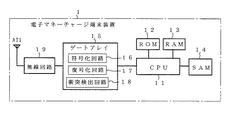
図1は、本発明に係る電子マネーチャージ端末装置の構成を示すブロック図である。本電子マネーチャージ端末装置(以下、端末装置)1は、後述の非接触ICカード(以下、ICカード)2と無線接続されてICカードに価値情報をチャージするものであり、CPU11と、CPU11が実行するプログラムを格納するROM12と、データを格納するRAM13と、ICカード2に対し価値情報のチャージや移動を行うための認証アルゴリズムを格納するSAM14と、ゲートアレイ15と、無線回路19と、ICカード2の後述のアンテナAT2と電磁結合するアンテナAT1とからなる。
【0007】
ここで、ゲートアレイ15には、CPU11からのデータを符号化して無線回路19に送出する符号化回路16と、アンテナAT1,無線回路19を介するICカード2からのデータを復号化してCPU11に送出する復号化回路17と、複数のICカードとの電磁結合時に複数のICカードから送出される後述の応答信号等のデータの衝突を検出する衝突検出回路18が設けられている。
【0008】
図2は、上述したICカード2の構成を示すブロック図であり、ICカード2は、CPU22,ROM23及び電気的に書き込み・消去が可能なメモリ24からなるICチップ21と、無線回路25と、上述のアンテナAT2とから構成される。
【0009】
さて、以上のように構成された電子マネーチャージシステムでは、ICカード2が端末装置1上に載置されると、ICカード2のアンテナAT2と、端末装置1のアンテナAT2とが電磁結合し、端末装置1からICカード2に電源が供給される。ICカード2のCPU22は電源が供給されると、無線回路25及びアンテナAT2を介し応答信号を端末装置1側へ送信する。
【0010】
端末装置1のCPU11は、アンテナAT1,無線回路19及びゲート回路15内の復号化回路17を介してその応答信号を受信すると、SAM14に格納された価値情報移転のための認証アルゴリズムを実行して、所定額の価値情報をICカード2側に送信しICカード2のメモリ24に格納させる。このようにしてICカード2に価値情報がチャージされる。
こうして、端末装置1により価値情報がチャージされたICカード2を用いて買い物等が行われ、ICカード2の残額が無くなってくると、そのICカード2に再度の価値情報のチャージが行われる。
【0011】
図3は、本発明の電子マネーチャージシステムの構成を示すブロック図であり、ICカード2を利用したバス乗車料金支払いシステムの例を示すものである。図3において、バス会社の営業所にはICカード2に価値情報をチャージする端末装置1A,1Bが設置され、各端末装置1A,1Bは、それぞれSAM14の認証アルゴリズムに基づきICカード2Aに価値情報をチャージするものである。この価値情報がチャージされたICカード2Aはバスの利用者に現金と引換に供給される。また、バスの運転手の集結場所であるバス会社本部には、端末装置1Cが設置され、端末装置1Cは、SAM14の認証アルゴリズムに基づきICカード2Bに価値情報をチャージするものである。この価値情報がチャージされたICカード2Bはバスの運転手に供給される。なお、各端末装置1A〜1Cは本部に設置されたセンタ3に接続され、各端末装置1A〜1CからICカードにチャージされた価値情報はセンタ3により一元管理される。
【0012】
ところで、価値情報がチャージされるICカード2のメモリ24は、2つの領域24A,24Bに分割されている。ここで、バスの利用者の所持するICカード2Aには、メモリ24の領域24Aに端末装置1Aまたは端末装置1Bから価値情報がチャージされる。また、運転手の所持するICカード2Bには、メモリ24の領域24Bに端末装置1Cから価値情報がチャージされる。
【0013】
バスの運転手は、バスの運行に先立ち、自身のICカード2Bを端末装置1Cに載置し、上述したように端末装置1Cから自身のICカード2Bのメモリ24の領域24Bに価値情報をチャージする。このICカード2Bにチャージされる価値情報は、例えば利用者が所持するICカード2Aにチャージされる価値情報の限度額(例えば1000円)の数十倍程度の額(例えば30000円)とする。
ここで、運行されるバスの中には利用者のICカード2Aからバス料金の引き落としを行う図4に示すような端末装置1Dが設置されている。この端末装置1Dは、ICカード2Aに価値情報をチャージする図1の端末装置1と同様に構成されており、利用者がバスからの下車時に自身のICカード2Aを端末装置1D上に載置すると、端末装置1Dは、SAM14の認証アルゴリズムに基づき、図4(a)に示すように利用者のICカード2Aのメモリ24の領域24Aの価値情報からバス乗車料金分に相当する金額を引き落とす。
【0014】
ここで、利用者のICカード2Aに価値情報が無い場合は、運転手は端末装置1D上に載置されている利用者のICカード2A上に、自身のICカード2Bを重ねて載置する。すると、ICカード2A,2Bの各アンテナAT2と、端末装置1DのアンテナAT1とが電磁結合し、各ICカード2A,2Bに端末装置1Dから電源が供給されることにより、各ICカード2A,2Bからそれぞれ固有のカード番号を示す前記応答信号が同時に送信される。したがって、各ICカード2A、2Bの送信データは衝突し、このデータの衝突が端末装置1Dの衝突検出回路18により検出されCPU11に伝達される。
【0015】
この場合、端末装置1DのCPU11は、端末装置1Dに複数のICカードが無線接続されていると認識して、衝突検出回路18により検出された衝突データに基づき各ICカードのカード番号を個別に指定して、指定したICカード2に対しそのカードのメモリ24の領域24Bに価値情報がチャージされているか否かの情報を返送させる。そしてその返送情報からそのICカード2が領域24Bに価値情報がチャージされている運転手用のICカード2Bと識別すると、端末装置1DのCPU11はSAM14の認証アルゴリズムに基づき、そのICカード2Bのメモリ24の領域24Bにチャージされている価値情報を所定額減じる。また、このとき端末装置1DのCPU11は、利用者のICカード2Aのカード番号を指定して同様にSAM14の認証アルゴリズムに基づきそのICカード2Aのメモリ24の領域24Aに前記所定額分の価値情報をチャージする。
【0016】
このようにして、運転手専用のICカード2Bから利用者のICカード2Aに価値情報が移転され、以降利用者はそのICカード2Aを利用してバス乗車料金の支払いを行うことができる。なお、運転手専用のICカード2Bから利用者のICカード2Aへの価値情報の移転時には移転した価値情報分の前記所定額が利用者から運転手に支払われる。
【0017】
このように、ICカード2に価値情報をチャージする端末装置1A,1Bと同様構成の端末装置1Dを引き落とし機としてバス内に設置するとともに、バス利用者のICカード2Aに残額が不足する場合は、このICカード2Aと運転手用のICカード2Bとを重ねて端末装置1D上に載置することにより、運転手用のICカード2Bからバス利用者のICカード2Aに価値情報を移転するようにしたものである。この結果、バス利用者は自身のICカード2Aに残額が無くなった場合に、逐一バス営業所まで赴いて、端末装置1Aまたは1Bにより価値情報をチャージする必要が無く、バス利用者の利便性が向上する。
ここで、バス利用者の中に運転手の知人がおりその知人の所持するICカード2Aに無料で価値情報をチャージするような運転手がいることも考えられるため、本実施の形態では、運転手専用のICカード2Bから利用者のICカード2Aへの価値情報の移転時には移転した価値情報分をICカード2Bから減算する。このように構成することにより、運転手の不正チャージを防止できる。
なお、端末装置1Dは、運転手のICカード2Bの価値情報を利用者のICカード2Aへ移転する時には、移転分に相当する価値情報を運転手のICカード2Bの価値情報から減算しないようにすることもできる。
【0018】
以上の実施の形態では、バスの乗車料金の支払いにICカード2を利用した例を説明したが、店舗に前記端末装置1Dを設置し、かつ店舗の店員用として、メモリ24の領域24Bに価値情報がチャージされたICカード2Bを供給するようにして、店舗で買い物を行いその代金支払いの際に利用者のICカード2Aに価値情報が無い場合には、前記端末装置1Dを利用して店員用のICカード2Bから利用者のICカード2Aに価値情報を移転することもできる。
【0019】
即ち、利用者のICカード2Aに残額が無い場合は、そのICカード2Aと店員用のICカード2Bとを端末装置1D上に載置する。すると、端末装置1Dは同様に、店員専用のICカード2Bのメモリ24内の領域24Bの価値情報を利用者のICカード2Aのメモリ24内の領域24Aに移転する。この結果、以降、利用者はそのICカード2Aの利用を続行することができる。したがって、この場合利用者は、特定の管理場所に赴きその場所に設置されているチャージ機によって価値情報をチャージする必要が無く、利用者の利便性が向上する。なお、端末装置1Dにより、店員用のICカード2Bから自身のICカード2Aに価値情報が移転された際には利用者は移転した価値情報分の金額を店員に支払う。
【0020】
【発明の効果】
以上説明したように本発明によれば、複数のICカードとの間の無線接続が検出されると、本端末装置は予め定めた第1のICカードのチャージエリアにチャージされている価値情報を第2のICカードのチャージエリアに移転するようにしたので、例えばバスの利用者は自身のICカードに残額が無くなった場合、バス内に設置されている本端末装置上に自身のICカードを運転者用の第1のICカードとともに載置すれば第1のICカードから価値情報を移転でき、したがって逐一バス営業所まで赴いてその営業所内のチャージ機により価値情報をチャージする必要が無く、バス利用者の利便性を向上できる。
この場合、価値情報がチャージされるICカードのエリアを第1及び第2のエリアに区分し、第1のICカードの第1のエリアの価値情報を第2のICカードの第2のエリアに移転するようにしたので、端末装置では価値情報を移転するICカードと価値情報が移転されるICカードとを的確に識別して価値情報の移転を行うことができる。
また、ICカードと、無線接続されたICカードに価値情報をチャージする第1の端末装置と、無線接続されたICカードに価値情報をチャージする第2の端末装置とからなる電子マネーチャージシステムにおいて、第2の端末装置は、複数のICカードとの間の無線接続を検出すると、予め定めた第1のICカードのチャージエリアにチャージされている価値情報を第2の非接触ICカードのチャージエリアに移転するようにしたので、例えばバス内に乗車料金引き落とし機として設置された第2の端末装置上に利用者の第2のICカードとともにバスの運転手専用の第1のICカードを載置すれば、第1のICカードから第2のICカードに価値移転が行われ、この結果、ICカードに価値情報が無くなった場合、バスの利用者はバス営業所まで赴いてその営業所内のチャージ機により価値情報をチャージする必要が無く、同様にバス利用者の利便性が向上する。また、店舗内に料金引き落とし機として第2の端末装置を設置しその第2の端末装置上に利用者の第2のICカードとともに店舗の店員専用の第1のICカードを載置すれば、第1のICカードから第2のICカードに同様に価値移転が行われるため、利用者は自身のICカードに残額が無くなった場合、特定の管理場所に設置されているチャージ機によりチャージする必要がなく、同様に利用者の利便性が向上する。
この場合、ICカードのチャージエリアを第1及び第2のエリアに区分し、第2の端末装置は、第1の非接触ICカードの第1のエリアの価値情報を第2の非接触ICカードの第2のエリアに移転するようにしたので、第2の端末装置は同様に価値情報を移転するICカードと価値情報が移転されるICカードとを的確に識別し価値情報を移転できる。
また、第1のICカードの価値情報を第2のICカードに移転する場合第1のカードの価値情報を引き落とすようにしたので、バス運転手による不正チャージを防止できる。
【図面の簡単な説明】
【図1】本発明に係る電子マネーチャージ端末装置の構成を示すブロック図である。
【図2】上記記端末装置により価値情報がチャージされる非接触ICカードの構成を示すブロック図である。
【図3】本発明の電子マネーチャージシステムの構成を示すブロック図である。
【図4】上記端末装置の非接触ICカードに対する価値情報のチャージの例を示す図である。
【符号の説明】
1,1A、1B,1C,1D…電子マネーチャージ端末装置、2,2A,2B…非接触ICカード、3…センタ、11,22…CPU、12,23…ROM、14…SAM、15…ゲートアレイ、16…符号化回路、17…復号化回路、18…衝突検出回路、19,25…無線回路、21…ICチップ、24…メモリ、24A…領域(第2のエリア)、24B…領域(第1のエリア)、AT1,AT2…アンテナ。[0001]
TECHNICAL FIELD OF THE INVENTION
The present invention relates to an electronic money charging terminal device and an electronic money charging system for charging IC card with value information.
[0002]
[Prior art]
In recent years, an electronic money system has been introduced in which value information is charged to an IC card as electronic money, and shopping or the like can be performed using the IC card charged with the value information.
In such an electronic money system, a charging machine for charging the IC card with the value information is arranged at a predetermined management place, and the user holds the IC card charged with the value information by the charging machine and has a store. Do shopping for example.
[0003]
Here, the user completes shopping at the store, places his or her IC card on the withdrawal machine installed at the store to pay for the price, and the clerk operates the withdrawal machine and pays for the shopping price. When the amount is input, the debit machine debits the amount corresponding to the purchase price from the value information charged in the IC card. In this way, shopping and the like are performed using the IC card charged with the value information, but when the remaining amount of the IC card becomes exhausted, the IC card is charged with the value information again by the charging machine.
[0004]
[Problems to be solved by the invention]
As described above, conventionally, when the remaining amount in the IC card is exhausted, the value information is charged again by the charging machine, but since the charging machine is installed only in a limited place for the purpose of preventing theft. However, there is a problem that charging of the value information to the IC card is troublesome.
Therefore, an object of the present invention is to make it possible to easily charge value information when the value information is lost in the IC card.
[0005]
[Means for Solving the Problems]
In order to solve such a problem, an electronic money charging terminal device of the present invention is a terminal device that is wirelessly connected to a contactless IC card and charges value information to the wirelessly connected contactless IC card. Detecting means for detecting a wireless connection with the plurality of non-contact IC cards, and detecting the wireless connection with the plurality of non-contact IC cards by the detecting means, It is characterized in that the value information charged in the first area of the first non-contact IC card is transferred to the second area of the second non-contact IC card .
Also, the present invention includes a non-contact IC card, a first terminal device for charging value information on the contactless IC card that is wirelessly connected, the second to charge the value information on the contactless IC card that is wirelessly connected An electronic money charge system comprising: a terminal device; a second terminal device, comprising: detecting means for detecting a wireless connection with a plurality of non-contact IC cards; When the wireless connection between the non-contact IC card is detected, the value information charged in the first area of the predetermined first non-contact IC card among the plurality of non-contact IC cards is stored in the second non-contact IC card. In the second area.
[0006]
BEST MODE FOR CARRYING OUT THE INVENTION
Hereinafter, the present invention will be described with reference to the drawings.
FIG. 1 is a block diagram showing a configuration of an electronic money charge terminal device according to the present invention. The electronic money charge terminal device (hereinafter, terminal device) 1 is wirelessly connected to a non-contact IC card (hereinafter, IC card) 2 described later to charge the IC card with value information, and the CPU 11 and the CPU 11 A ROM 12 for storing a program to be executed, a RAM 13 for storing data, a SAM 14 for storing an authentication algorithm for charging and moving value information to and from the
[0007]
Here, the gate array 15 encodes the data from the CPU 11 and sends it to the
[0008]
FIG. 2 is a block diagram showing the configuration of the above-described
[0009]
Now, in the electronic money charge system configured as described above, when the
[0010]
When receiving the response signal via the antenna AT1, the
In this way, shopping or the like is performed using the
[0011]
FIG. 3 is a block diagram showing the configuration of the electronic money charge system according to the present invention, and shows an example of a bus fare payment system using the
[0012]
By the way, the
[0013]
Prior to the operation of the bus, the bus driver places his / her
Here, a terminal device 1D as shown in FIG. 4 for deducting a bus fee from the user's
[0014]
If there is no value information on the user's
[0015]
In this case, the CPU 11 of the terminal device 1D recognizes that a plurality of IC cards are wirelessly connected to the terminal device 1D, and individually identifies the card numbers of the IC cards based on the collision data detected by the
[0016]
In this way, the value information is transferred from the driver-
[0017]
As described above, when the terminal device 1D having the same configuration as the terminal devices 1A and 1B for charging the
Here, it is conceivable that a bus acquaintance has a driver's acquaintance and a driver who charges the
When transferring the value information of the driver's
[0018]
In the above-described embodiment, the example in which the
[0019]
That is, when there is no remaining amount in the user's
[0020]
【The invention's effect】
As described above, according to the present invention, when a wireless connection with a plurality of IC cards is detected, the terminal device transmits value information charged in a predetermined charge area of the first IC card. Since the transfer to the charge area of the second IC card is made, for example, when the user of the bus runs out of balance in his or her own IC card, his / her IC card is placed on the terminal installed in the bus. If placed together with the first IC card for the driver, the value information can be transferred from the first IC card, so that it is not necessary to go to the bus office every time and charge the value information by the charging machine in the office, The convenience for bus users can be improved.
In this case, the area of the IC card in which the value information is charged is divided into first and second areas, and the value information of the first area of the first IC card is stored in the second area of the second IC card. Since the transfer is performed, the terminal device can transfer the value information by accurately identifying the IC card to which the value information is to be transferred and the IC card to which the value information is to be transferred.
Further, in an electronic money charging system comprising an IC card, a first terminal device for charging value information to a wirelessly connected IC card, and a second terminal device for charging value information to a wirelessly connected IC card. When the second terminal device detects a wireless connection with a plurality of IC cards, the value information charged in the predetermined charge area of the first IC card is charged to the second non-contact IC card. Since the terminal is moved to the area, for example, the first IC card dedicated to the bus driver is mounted together with the second IC card of the user on the second terminal device installed as a fare reduction machine in the bus. If the value is transferred from the first IC card to the second IC card, and the value information is lost on the IC card, the bus user can operate the bus. There is no need to charge the value information by the charge machine of the business office and went to the place, as well as the convenience of the bus user is improved. Also, if a second terminal device is installed in the store as a charge reduction machine, and a first IC card dedicated to a store clerk is placed on the second terminal device together with the user's second IC card, Since the value transfer is similarly performed from the first IC card to the second IC card, the user needs to charge the IC card using a charging machine installed at a specific management place when the remaining balance is exhausted. And the convenience of the user is similarly improved.
In this case, the charge area of the IC card is divided into a first area and a second area, and the second terminal device transmits the value information of the first area of the first non-contact IC card to the second non-contact IC card. Is transferred to the second area, the second terminal device can also appropriately identify the IC card to which the value information is to be transferred and the IC card to which the value information is to be transferred, and transfer the value information.
Further, when transferring the value information of the first IC card to the second IC card, the value information of the first card is debited, so that unauthorized charging by the bus driver can be prevented.
[Brief description of the drawings]
FIG. 1 is a block diagram showing a configuration of an electronic money charge terminal device according to the present invention.
FIG. 2 is a block diagram showing a configuration of a contactless IC card in which value information is charged by the terminal device.
FIG. 3 is a block diagram showing a configuration of an electronic money charging system of the present invention.
FIG. 4 is a diagram showing an example of charging of value information to a contactless IC card of the terminal device.
[Explanation of symbols]
1, 1A, 1B, 1C, 1D: electronic money charge terminal device, 2, 2A, 2B: non-contact IC card, 3: center, 11, 22, CPU, 12, 23 ROM, 14 SAM, 15 gate Array, 16: Encoding circuit, 17: Decoding circuit, 18: Collision detection circuit, 19, 25: Wireless circuit, 21: IC chip, 24: Memory, 24A: Area (second area), 24B: Area ( (First area), AT1, AT2... Antennas.
Claims (2)
複数の非接触ICカードとの間の無線接続を検出する検出手段と、
前記検出手段により少なくとも2つの非接触ICカードとの間の無線接続が検出されると、複数の非接触ICカードのうち予め定めた第1の非接触ICカードのチャージエリアにチャージされている価値情報を第2の非接触ICカードのチャージエリアに移転する価値情報移転手段と
を備え、
前記価値情報がチャージされる非接触ICカードのチャージエリアは第1及び第2のエリアに区分され、
前記価値情報移転手段は、第1の非接触ICカードの第1のエリアの価値情報を第2の非接触ICカードの第2のエリアに移転することを特徴とする電子マネーチャージ端末装置。An electronic money charge terminal device wirelessly connected to the non-contact IC card and charging value information to the non-contact IC card wirelessly connected,
Detecting means for detecting a wireless connection with a plurality of contactless IC cards;
When a wireless connection between at least two non-contact IC cards is detected by the detection means, a value charged in a predetermined first non-contact IC card charging area of the plurality of non-contact IC cards. Value information transfer means for transferring information to a charge area of the second contactless IC card ,
The charge area of the contactless IC card in which the value information is charged is divided into a first area and a second area,
The electronic money charge terminal device, wherein the value information transfer means transfers the value information of the first area of the first non-contact IC card to the second area of the second non-contact IC card .
前記第2の電子マネーチャージ端末装置は、
複数の非接触ICカードとの間の無線接続を検出する検出手段と、
前記検出手段により少なくとも2つの非接触ICカードとの間の無線接続が検出されると、複数の非接触ICカードのうち予め定めた第1の非接触ICカードのチャージエリアにチャージされている価値情報を第2の非接触ICカードのチャージエリアに移転する価値情報移転手段と
を備え、
前記価値情報がチャージされる非接触ICカードのチャージエリアは第1及び第2のエリアに区分され、
前記価値情報移転手段は、第1の非接触ICカードの第1のエリアの価値情報を第2の非接触ICカードの第2のエリアに移転することを特徴とする電子マネーチャージシステム。A non-contact IC card, a first electronic money charging terminal wirelessly connected to the non-contact IC card and charging value information to the non-contact IC card wirelessly connected, and a non-contact IC wirelessly connected In an electronic money charging system including a second electronic money charging terminal device for charging value information to a card,
The second electronic money charge terminal device comprises:
Detecting means for detecting a wireless connection with a plurality of contactless IC cards;
When a wireless connection between at least two non-contact IC cards is detected by the detection means, a value charged in a predetermined first non-contact IC card charging area of the plurality of non-contact IC cards. Value information transfer means for transferring information to a charge area of the second contactless IC card ,
The charge area of the contactless IC card in which the value information is charged is divided into a first area and a second area,
The electronic money charge system, wherein the value information transfer means transfers the value information of the first area of the first non-contact IC card to the second area of the second non-contact IC card .
Priority Applications (1)
| Application Number | Priority Date | Filing Date | Title |
|---|---|---|---|
| JP6458099A JP3577567B2 (en) | 1999-03-11 | 1999-03-11 | Electronic money charge terminal device and electronic money charge system |
Applications Claiming Priority (1)
| Application Number | Priority Date | Filing Date | Title |
|---|---|---|---|
| JP6458099A JP3577567B2 (en) | 1999-03-11 | 1999-03-11 | Electronic money charge terminal device and electronic money charge system |
Publications (2)
| Publication Number | Publication Date |
|---|---|
| JP2000259901A JP2000259901A (en) | 2000-09-22 |
| JP3577567B2 true JP3577567B2 (en) | 2004-10-13 |
Family
ID=13262334
Family Applications (1)
| Application Number | Title | Priority Date | Filing Date |
|---|---|---|---|
| JP6458099A Expired - Fee Related JP3577567B2 (en) | 1999-03-11 | 1999-03-11 | Electronic money charge terminal device and electronic money charge system |
Country Status (1)
| Country | Link |
|---|---|
| JP (1) | JP3577567B2 (en) |
Families Citing this family (7)
| Publication number | Priority date | Publication date | Assignee | Title |
|---|---|---|---|---|
| KR100485939B1 (en) * | 2002-06-27 | 2005-04-28 | 케이비 테크놀러지 (주) | Smart card for member stores which join electric money chargig service |
| JP2009048488A (en) * | 2007-08-21 | 2009-03-05 | Sony Corp | Electronic wallet device, and method and program for using electronic value |
| JP5286714B2 (en) | 2007-08-23 | 2013-09-11 | ソニー株式会社 | Electronic wallet device, electronic value utilization method and program |
| JP4403433B2 (en) | 2007-08-23 | 2010-01-27 | ソニー株式会社 | Electronic wallet device, communication method and program |
| JP5018339B2 (en) | 2007-08-23 | 2012-09-05 | ソニー株式会社 | Signal processing apparatus, signal processing method, and program |
| JP2012027804A (en) * | 2010-07-27 | 2012-02-09 | Hitachi Ltd | Value information movement method and system |
| CN108648333A (en) * | 2018-04-26 | 2018-10-12 | 淮阴师范学院 | A kind of bus is deducted fees system |
-
1999
- 1999-03-11 JP JP6458099A patent/JP3577567B2/en not_active Expired - Fee Related
Also Published As
| Publication number | Publication date |
|---|---|
| JP2000259901A (en) | 2000-09-22 |
Similar Documents
| Publication | Publication Date | Title |
|---|---|---|
| US7255264B2 (en) | Cellular phone-based automatic payment system | |
| US5828044A (en) | Non-contacting type radio frequency recognizing credit card system | |
| US8011588B2 (en) | Electronic wallet device and method of using electronic value | |
| CN104103128B (en) | Contactless disablement device and method | |
| WO2003094375A1 (en) | Charge approval and payment system | |
| AU683196B2 (en) | Non-contacting type radio frequency recognizing credit card system | |
| JPH10307885A (en) | Electronic money system, electronic money card, electronic money transaction method, recording medium | |
| JP3577567B2 (en) | Electronic money charge terminal device and electronic money charge system | |
| EP1512125B1 (en) | Method to pay with a smart card | |
| WO2013001133A1 (en) | Bank-card fraud detection and prevention for bank automats | |
| KR100678772B1 (en) | A small sum paying system and a refill system using mobile having a RF chip | |
| KR100645232B1 (en) | Total billing system of traffic fare and mobile telecmmuication charge | |
| KR100730508B1 (en) | The traffic card and settlement method which uses the USB and the RFID-Chip | |
| KR20090028296A (en) | System for charging and settling electronic cash, and method therefor | |
| JP4178785B2 (en) | Information processing terminal and control method thereof | |
| KR101627105B1 (en) | Method of providing deposit-based integrated-processing of electronic cash transaction for multiple formats of RF cards using NFC function of smart terminals, and computer-readable recording medium for the same | |
| US11568403B2 (en) | Vehicle toll transponder for enabling multiple transaction cards and securely providing transaction card details | |
| KR100483207B1 (en) | Method for loading value to electronic purse | |
| JP4037516B2 (en) | Device for preventing unauthorized use of automatic fee collection system | |
| KR20100003264A (en) | Terminal for transport means | |
| KR20040017396A (en) | Combined prepayment/postpayment e-cash payment processing method and apparatus | |
| KR20000037186A (en) | A small sum paying system and a refill system using black list mobile information | |
| AU2005228675A1 (en) | Method and device for verifying fee payment | |
| JP2000259875A (en) | Charge collecting system and charge collecting method | |
| KR20100003263A (en) | Card for transport means |
Legal Events
| Date | Code | Title | Description |
|---|---|---|---|
| A977 | Report on retrieval |
Free format text: JAPANESE INTERMEDIATE CODE: A971007 Effective date: 20040122 |
|
| A131 | Notification of reasons for refusal |
Free format text: JAPANESE INTERMEDIATE CODE: A131 Effective date: 20040203 |
|
| A521 | Written amendment |
Free format text: JAPANESE INTERMEDIATE CODE: A523 Effective date: 20040405 |
|
| A711 | Notification of change in applicant |
Free format text: JAPANESE INTERMEDIATE CODE: A712 Effective date: 20040506 |
|
| TRDD | Decision of grant or rejection written | ||
| A01 | Written decision to grant a patent or to grant a registration (utility model) |
Free format text: JAPANESE INTERMEDIATE CODE: A01 Effective date: 20040615 |
|
| RD03 | Notification of appointment of power of attorney |
Free format text: JAPANESE INTERMEDIATE CODE: A7423 Effective date: 20040616 |
|
| A61 | First payment of annual fees (during grant procedure) |
Free format text: JAPANESE INTERMEDIATE CODE: A61 Effective date: 20040628 |
|
| R150 | Certificate of patent or registration of utility model |
Free format text: JAPANESE INTERMEDIATE CODE: R150 |
|
| S531 | Written request for registration of change of domicile |
Free format text: JAPANESE INTERMEDIATE CODE: R313531 |
|
| R350 | Written notification of registration of transfer |
Free format text: JAPANESE INTERMEDIATE CODE: R350 |
|
| FPAY | Renewal fee payment (event date is renewal date of database) |
Free format text: PAYMENT UNTIL: 20070723 Year of fee payment: 3 |
|
| FPAY | Renewal fee payment (event date is renewal date of database) |
Free format text: PAYMENT UNTIL: 20080723 Year of fee payment: 4 |
|
| FPAY | Renewal fee payment (event date is renewal date of database) |
Free format text: PAYMENT UNTIL: 20090723 Year of fee payment: 5 |
|
| FPAY | Renewal fee payment (event date is renewal date of database) |
Free format text: PAYMENT UNTIL: 20100723 Year of fee payment: 6 |
|
| FPAY | Renewal fee payment (event date is renewal date of database) |
Free format text: PAYMENT UNTIL: 20100723 Year of fee payment: 6 |
|
| FPAY | Renewal fee payment (event date is renewal date of database) |
Free format text: PAYMENT UNTIL: 20110723 Year of fee payment: 7 |
|
| FPAY | Renewal fee payment (event date is renewal date of database) |
Free format text: PAYMENT UNTIL: 20110723 Year of fee payment: 7 |
|
| FPAY | Renewal fee payment (event date is renewal date of database) |
Free format text: PAYMENT UNTIL: 20120723 Year of fee payment: 8 |
|
| FPAY | Renewal fee payment (event date is renewal date of database) |
Free format text: PAYMENT UNTIL: 20120723 Year of fee payment: 8 |
|
| FPAY | Renewal fee payment (event date is renewal date of database) |
Free format text: PAYMENT UNTIL: 20130723 Year of fee payment: 9 |
|
| LAPS | Cancellation because of no payment of annual fees |