JP3575415B2 - Printing up to the edge of the printing paper without soiling the platen - Google Patents
Printing up to the edge of the printing paper without soiling the platen Download PDFInfo
- Publication number
- JP3575415B2 JP3575415B2 JP2000294074A JP2000294074A JP3575415B2 JP 3575415 B2 JP3575415 B2 JP 3575415B2 JP 2000294074 A JP2000294074 A JP 2000294074A JP 2000294074 A JP2000294074 A JP 2000294074A JP 3575415 B2 JP3575415 B2 JP 3575415B2
- Authority
- JP
- Japan
- Prior art keywords
- dot
- printing
- groove
- print medium
- sub
- Prior art date
- Legal status (The legal status is an assumption and is not a legal conclusion. Google has not performed a legal analysis and makes no representation as to the accuracy of the status listed.)
- Expired - Lifetime
Links
Images


Description
【0001】
【発明の属する技術分野】
この発明は、ドット記録ヘッドを用いて記録媒体の表面にドットの記録を行う技術に関し、特に、プラテンを汚すことなく印刷用紙の端部まで印刷を行う技術に関する。
【0002】
【従来の技術】
近年、コンピュータの出力装置として、印刷ヘッドのノズルからインクを吐出するプリンタが広く普及している。図30は、従来のプリンタの印刷ヘッドの周辺を示す側面図である。印刷用紙Pは、プラテン26o上でヘッド28oに向かい合うように支持される。そして、印刷用紙Pは、プラテン26oの上流に配された上流側紙送りローラ25p,25q、およびプラテン26oの下流に配された下流側紙送りローラ25r,25sによって、矢印Aの方向に送られる。ヘッドからインクが吐出されると、印刷用紙P上に順次、ドットが記録されて、画像が印刷される。
【0003】
【発明が解決しようとする課題】
上記のようなプリンタにおいて印刷用紙の端まで画像を印刷しようとすると、印刷用紙の端が印刷ヘッド下方、すなわちプラテン上に位置するように印刷用紙を配し、印刷ヘッドからインク滴を吐出させる必要がある。しかし、そのような印刷においては、印刷用紙の送りの誤差やインク滴の着弾位置のずれなどによって、インク滴が本来着弾すべき印刷用紙端部からはずれてプラテン上に着弾してしまう場合がある。そのような場合には、プラテン上に着弾したインクによって、その後にプラテン上を通過する印刷用紙が、汚されてしまう。
【0004】
この発明は、従来技術における上述の課題を解決するためになされたものであり、プラテンにインク滴を着弾させることなく印刷用紙の端部まで印刷を行う技術を提供することを目的とする。
【0005】
【課題を解決するための手段およびその作用・効果】
上述の課題の少なくとも一部を解決するため、本発明では、インク滴を吐出する複数のドット形成要素が設けられたドット記録ヘッドを用いて印刷媒体の表面にドットの記録を行うドット記録装置を対象として、所定の処理を行う。このドット記録装置は、主走査の行路の少なくとも一部においてドット形成要素と向かい合うように、主走査の方向に延長して設けられ、印刷媒体をドット記録ヘッドと向かい合うように支持し、複数のドット形成要素のうちの一部のドット形成要素と向かい合う位置に主走査の方向に延長して設けられる溝部を有している、プラテンを備えている。
【0006】
そのような印刷装置において実施する印刷(ドットの記録)は、ドット記録ヘッドと印刷媒体の少なくとも一方を駆動して主走査を行いつつ、複数のドット形成要素のうちの少なくとも一部を駆動してドットの形成を行い、主走査の合間に印刷媒体を主走査の方向と交わる方向に駆動して副走査を行うドット記録である。その際、印刷媒体の端部近傍において、第1の記録モードでドットの記録を行うとともに、印刷媒体がプラテンに支持され、かつ、印刷媒体の上端または下端が溝部の開口上にあるときに、溝部と向かい合う位置にあるドット形成要素の少なくとも一部からインク滴を吐出させて、印刷媒体上にドットを形成する、端部印刷を実施する。そして、印刷媒体の中間部分において、最大の副走査送り量が第1の記録モードにおける最大の副走査送り量よりも大きい第2の記録モードでドットの記録を行う。
【0007】
このような態様とすれば、溝部と向かい合う位置にあるドット形成要素を使用して、プラテンにインク滴を着弾させることなく、印刷用紙の端部まで余白なく印刷を行うことができる。
【0008】
また、端部印刷を実施する際には、溝部と向かい合う位置にあるドット形成要素以外のドット形成要素からはインク滴を吐出させないようにすることが好ましい。このような態様とすれば、印刷媒体の上端の印刷において、それまでの印刷媒体の副走査の送り量が不足で、上端が溝部上にまで達しなかった場合、すなわち、印刷媒体の上端がプラテン上に位置し、プラテンの一部が直接ドット記録ヘッドと向き合うこととなった場合にも、プラテンがインク滴によって汚されることがない。印刷媒体の下端の印刷において、印刷媒体の副走査の送り量が過大で、印刷媒体の下端が溝部上を通過してしまった場合についても同様である。
【0009】
溝部を、複数のドット形成要素のうち少なくとも副走査の方向の下流側の端に位置するドット形成要素と向かい合う位置に設けた場合には、印刷媒体の上端が溝部の開口上にあるときに、端部印刷を実施することが好ましい。このような態様とすれば、印刷媒体の上端に余白なく画像を記録することができる。
【0010】
また、溝部を、複数のドット形成要素のうち少なくとも副走査の方向の上流側の端に位置するドット形成要素と向かい合う位置に設けた場合には、印刷媒体の下端が溝部の開口上にあるときに、端部印刷を実施することが好ましい。このような態様とすれば、印刷媒体の下端に余白なく画像を記録することができる。
【0011】
なお、印刷装置において副走査を実施する副走査駆動部が、前記ドット記録ヘッドに対して副走査方向の上流側に設けられ、前記印刷媒体を保持して前記印刷媒体を駆動する上流副走査駆動部と、前記ドット記録ヘッドに対して副走査方向の下流側に設けられ、前記印刷媒体を保持して前記印刷媒体を駆動する下流副走査駆動部と、を備える態様においては、上記のようなドットの記録は次のような利点を有する。
【0012】
上記のような印刷装置においては、印刷媒体の端部の印刷の際には、上流副走査駆動部と下流副走査駆動部いずれか一方のみで副走査を行わなければならない。このような印刷装置において、上記のような印刷を行えば、上流副走査駆動部と下流副走査駆動部いずれか一方のみで副走査を行って印刷を実施する距離を短くすることができる。
【0013】
なお、第1の記録モードで実行される副走査送りは、1ドット単位の副走査送りであることが好ましい。このようにすれば、ドット記録ヘッドにおいて副走査方向の端部に近いノズルで印刷媒体の端部を記録することができる。
【0014】
なお、上記のような印刷に際しては、印刷媒体に対して、記録すべき画像が、端部印刷が実施される端部を超えて印刷媒体の外側まで設定された画像データを生成し、その画像データに基づいてドットを形成することが好ましい。そのようにすれば、印刷媒体の位置決め誤差が存在する場合にも、印刷媒体の外側に設定された画像に基づいて、想定位置からはみ出た部分の印刷媒体に印刷を行うことができる。
【0015】
さらに、画像データにおいて、画像の、印刷媒体の端部印刷が実施される端部を超える部分の寸法は、溝部の幅未満に設定されることが好ましい。そのようにすれば、印刷媒体の端部印刷が実施される端部を超えて設定される部分を記録するためのインク滴が、印刷媒体上に着弾しなかった場合についても、それらのインク滴を溝部内に着弾させるように、印刷媒体をドット記録ヘッドに対して位置決めすることができる。
【0016】
なお、本発明は、以下に示すような種々の態様で実現することが可能である。
(1)ドット記録方法、印刷制御方法、印刷方法。
(2)ドット記録装置、印刷制御装置、印刷装置。
(3)上記の装置や方法を実現するためのコンピュータプログラム。
(4)上記の装置や方法を実現するためのコンピュータプログラムを記録した記録媒体。
(5)上記の装置や方法を実現するためのコンピュータプログラムを含み搬送波内に具現化されたデータ信号。
【0017】
【発明の実施の形態】
以下で、本発明の実施の形態を実施例に基づいて以下の順序で説明する。
A.実施形態の概要:
B.第1実施例:
C.第2実施例:
D.第3実施例:
E.側方溝部を有する態様:
F.変形例:
【0018】
A.実施形態の概要:
図1は、本発明の実施の形態におけるインクジェットプリンタの印刷ヘッドの周辺の構造を示す側面図である。図1においては、印刷用紙Pが上流側紙送りローラ25a,25bに保持されて、送られており(副走査送り)、その前端Pfが上流側溝部26f上およびプラテン26上を通過して、下流側溝部26rの開口の上に至っている。このとき印刷ヘッド28からインク滴Ipを吐出して印刷を開始する。印刷用紙Pの前端Pfがノズル#1よりも後にあるときに印刷を開始するので、多少の紙送り誤差があっても、印刷用紙Pの前端部Pfに余白を作ることなく端まで画像を印刷することができる。印刷用紙Pに着弾しなかったインク滴は、吸収部材27rに吸収される。
【0019】
印刷用紙Pの前端Pf近傍の印刷の際には、送り量が1ドットである微小な副走査送りを繰り返して印刷を行うことが好ましい。そうすることにより、印刷用紙前端部分を下流側溝部26r上において印刷することが容易となる。
【0020】
図2は、印刷用紙Pの後端Prにおける印刷の様子を示している。図2においては、印刷の最終段階において、印刷用紙Pが下流側紙送りローラ25c,25dのみに保持されて、送られており、その後端Prが下流側溝部26rの開口の上に至っている。このとき印刷ヘッド28からインク滴を吐出して印刷用紙後端部の印刷を行う。印刷用紙Pの後端Prがノズル#8よりも前にあるときに印刷を行うので、多少の紙送り誤差があっても、印刷用紙の後端部Prに余白を作ることなく端まで画像を印刷することができる。印刷用紙Pに着弾しなかったインク滴は、吸収部材27fに吸収される。
【0021】
印刷用紙の後端Pr近傍の印刷の際にも、微小な副走査送りを繰り返して印刷を行うことが好ましい。そうすることにより、印刷用紙後端部分を上流側溝部26f上において印刷することが容易となる。
【0022】
B.第1実施例:
(1)装置の構成:
図3は、本発明の実施例としての画像処理装置および印刷装置の構成を示すブロック図である。図示するように、コンピュータ90にスキャナ12とプリンタ22とが接続されている。このコンピュータ90に所定のプログラムがロードされ実行されることにより画像処理装置として機能する他、プリンタ22と併せて印刷装置として機能する。このコンピュータ90は、プログラムに従って画像処理に関わる動作を制御するための各種演算処理を実行するCPU81を中心に、バス80により相互に接続された次の各部を備える。ROM82は、CPU81で各種演算処理を実行するのに必要な各種プログラムやデータを予め格納しており、RAM83は、同じくCPU81で各種演算処理を実行するのに必要な各種プログラムやデータが一時的に読み書きされるメモリである。入力インタフェース84は、スキャナ12やキーボード14からの信号の入力を司り、出力インタフェース85は、プリンタ22へのデータの出力を司る。CRTC86は、カラー表示可能なCRT21への信号出力を制御し、ディスクコントローラ(DDC)87は、ハードディスク16やフレキシブルドライブ15あるいは図示しないCD−ROMドライブとの間のデータの授受を制御する。ハードディスク16には、RAM83にロードされて実行される各種プログラムやデバイスドライバの形式で提供される各種プログラムなどが記憶されている。
【0023】
この他、バス80には、シリアル入出力インタフェース(SIO)88が接続されている。このSIO88は、モデム18に接続されており、モデム18を介して、公衆電話回線PNTに接続されている。コンピュータ90は、このSIO88およびモデム18を介して、外部のネットワークに接続されており、特定のサーバSVに接続することにより、画像処理に必要なプログラムをハードディスク16にダウンロードすることも可能である。また、必要なプログラムをフレキシブルディスクFDやCD−ROMによりロードし、コンピュータ90に実行させることも可能である。
【0024】
図4は、本印刷装置のソフトウェアの構成を示すブロック図である。コンピュータ90では、所定のオペレーティングシステムの下で、アプリケーションプログラム95が動作している。オペレーティングシステムには、ビデオドライバ91やプリンタドライバ96が組み込まれており、アプリケーションプログラム95からは、これらのドライバを介して、プリンタ22に転送するための画像データDが出力されることになる。画像のレタッチなどを行うアプリケーションプログラム95は、スキャナ12から画像を読み込み、これに対して所定の処理を行いつつビデオドライバ91を介してCRT21に画像を表示している。スキャナ12から供給されるデータORGは、カラー原稿から読み取られ、レッド(R)、グリーン(G)、ブルー(B)の3色の色成分からなる原カラー画像データORGである。
【0025】
このアプリケーションプログラム95が、印刷命令を発すると、コンピュータ90のプリンタドライバ96が、画像データをアプリケーションプログラム95から受け取り、これをプリンタ22が処理可能な信号(ここではシアン、マゼンタ、ライトシアン、ライトマゼンタ、イエロ、ブラックの各色についての多値化された信号)に変換している。図4に示した例では、プリンタドライバ96の内部には、解像度変換モジュール97と、色補正モジュール98と、ハーフトーンモジュール99と、ラスタライザ100とが備えられている。また、色補正テーブルLUT、ドット形成パターンテーブルDTも記憶されている。なお、アプリケーションプログラム95が特許請求の範囲にいう「画像データ生成部」に相当する。
【0026】
解像度変換モジュール97は、アプリケーションプログラム95が扱っているカラー画像データの解像度、即ち、単位長さ当りの画素数をプリンタドライバ96が扱うことができる解像度に変換する役割を果たす。こうして解像度変換された画像データは、まだRGBの3色からなる画像情報であるから、色補正モジュール98は色補正テーブルLUTを参照しつつ、各画素ごとにプリンタ22が使用するシアン(C)、マゼンタ(M)、ライトシアン(LC)、ライトマゼンタ(LM)、イエロ(Y)、ブラック(K)の各色のデータに変換する。
【0027】
色補正されたデータは、例えば256階調等の幅で階調値を有している。ハーフトーンモジュール99は、ドットを分散して形成することによりプリンタ22で、この階調値を表現するためのハーフトーン処理を実行する。ハーフトーンモジュール99は、ドット形成パターンテーブルDTを参照することにより、画像データの階調値に応じて、それぞれのインクドットのドット形成パターンを設定した上で、ハーフトーン処理を実行する。こうして処理された画像データは、ラスタライザ100によりプリンタ22に転送すべきデータ順に並べ替えられ、最終的な印刷データPDとして出力される。印刷データPDは、各主走査時のドットの記録状態を表すラスタデータと副走査送り量を示すデータとを含んでいる。本実施例では、プリンタ22は印刷データPDに従ってインクドットを形成する役割を果たすのみであり画像処理は行っていないが、勿論これらの処理をプリンタ22で行うものとしても差し支えない。
【0028】
次に、図5によりプリンタ22の概略構成を説明する。図示するように、このプリンタ22は、紙送りモータ23によって用紙Pを搬送する機構と、キャリッジモータ24によってキャリッジ31をプラテン26の軸方向に往復動させる機構と、キャリッジ31に搭載された印刷ヘッド28を駆動してインクの吐出およびインクドットの形成を行う機構と、これらの紙送りモータ23、キャリッジモータ24、印刷ヘッド28および操作パネル32との信号のやり取りを司る制御回路40とから構成されている。
【0029】
キャリッジ31をプラテン26の軸方向に往復動させる機構は、プラテン26の軸と平行に架設され、キャリッジ31を摺動可能に保持する摺動軸34とキャリッジモータ24との間に無端の駆動ベルト36を張設するプーリ38と、キャリッジ31の原点位置を検出する位置検出センサ39等から構成されている。
【0030】
キャリッジ31には、黒インク(K)用のカートリッジ71とシアン(C),ライトシアン(LC)、マゼンタ(M),ライトマゼンダ(LM)、イエロ(Y)の6色のインクを収納したカラーインク用カートリッジ72が搭載可能である。キャリッジ31の下部の印刷ヘッド28には計6個のインク吐出用ヘッド61ないし66が形成されており、キャリッジ31の底部には、この各色用ヘッドにインクタンクからのインクを導く導入管67が立設されている。キャリッジ31に黒(K)インク用のカートリッジ71およびカラーインク用カートリッジ72を上方から装着すると、各カートリッジに設けられた接続孔に導入管67が挿入され、各インクカートリッジから吐出用ヘッド61ないし66へのインクの供給が可能となる。
【0031】
キャリッジ31下部に設けられた各色のヘッド61ないし66には、各色ごとに48個のノズルNzが設けられており、各ノズル毎に、電歪素子の一つであって応答性に優れたピエゾ素子PEが配置されている。ピエゾ素子PEは、ノズルNzまでインクを導くインク通路に接する位置に設置されている。ピエゾ素子PEは、周知のように、電圧の印加により結晶構造が歪み、極めて高速に電気−機械エネルギの変換を行う素子である。本実施例では、ピエゾ素子PEの両端に設けられた電極間に所定時間幅の電圧を印加することにより、ピエゾ素子PEが電圧の印加時間だけ伸張し、インク通路の一側壁を変形させる。この結果、インク通路68積はピエゾ素子PEの伸張に応じて収縮し、この収縮分に相当するインクが、粒子Ipとなって、ノズルNzの先端から高速に吐出される。このインク粒子Ipがプラテン26に装着された用紙Pに染み込むことにより、印刷が行われる。
【0032】
図6は、インク吐出用ヘッド61〜66におけるインクジェットノズルNzの配列を示す説明図である。これらのノズルの配置は、ブラック(K)、シアン(C)、ライトシアン(LC)、マゼンタ(M)、ライトマゼンダ(LM)、イエロ(Y)各色ごとにインクを吐出する6組のノズルアレイから成っており、それぞれ48個のノズルが一定のノズルピッチkで一列に配列されている。なお、「ノズルピッチ」とは、印刷ヘッド上に配されるノズルの副走査方向の間隔が何ラスタ分(すなわち、何画素分)であるかを示す値である。例えば、間に3ラスタ分の間隔をあけて配されているノズルのピッチkは4である。
【0033】
図7は、プラテン26の周辺を示す平面図である。プラテン26は、主走査の方向に、このプリンタ22で使用可能な印刷用紙Pの最大幅よりも長く設けられている。そして、プラテン26の上流には、上流側紙送りローラ25a、25bが設けられている。上流側紙送りローラ25aが一つの駆動ローラであるのに対し、上流側紙送りローラ25bは自由に回転する複数の小ローラである。また、プラテンの下流には、下流側紙送りローラ25c、25dが設けられている。下流側紙送りローラ25cが駆動軸に設けられた複数のローラであり、下流側紙送りローラ25dは自由に回転する複数の小ローラである。下流側紙送りローラ25dの外周面には、回転軸方向に平行に溝が設けられている。すなわち、下流側紙送りローラ25dは、外周面に放射状に歯(溝と溝の間の部分)を有しており、回転軸方向から見た場合に歯車状の形状に見える。この下流側紙送りローラ25dは、通称「ギザローラ」と呼ばれ、印刷用紙Pをプラテン26上に押しつける役割を果たす。なお、下流側紙送りローラ25cと上流側紙送りローラ25aとは、外周の速さが等しくなるように同期して回転する。
【0034】
印刷ヘッド28は、これらの上流側紙送りローラ25a、25bおよび下流側紙送りローラ25c、25dに挟まれたプラテン26上を主走査において往復動する。印刷用紙Pは、上流側紙送りローラ25a、25bおよび下流側紙送りローラ25c、25dに保持され、その間の部分をプラテン26の上面によって印刷ヘッド28のノズル列と向かい合うように支持される。そして、上流側紙送りローラ25a、25bおよび下流側紙送りローラ25c、25dによって副走査送りを実施されて、印刷ヘッド28のノズルから吐出されるインクにより順次画像を記録される。なお、この上流側紙送りローラ25a、25bが特許請求の範囲にいう「上流側副走査駆動部」であり、下流側紙送りローラ25c,25dが特許請求の範囲にいう「下流側副走査駆動部」である。
【0035】
また、プラテン26には、副走査方向の上流側および下流側にそれぞれ上流側溝部26fと下流側溝部26rが設けられている。上流側溝部26fと下流側溝部26rは、それぞれ主走査方向に沿って、このプリンタ22で使用可能な印刷用紙Pの最大幅よりも長く設けられている。また、これら上流側溝部26fと下流側溝部26rの底部にはそれぞれインク滴Ipを受けてこれを吸収するための吸収部材27f,27rが配されている。そして、下流側溝部26rは、印刷ヘッド28上のノズルNzのうち最下流のノズルを含む下流側の一部のノズル群Nr(図7において斜線で示す部分のノズル)と向かい合う位置に設けられている。そして、上流側溝部26fは、印刷ヘッド28上のノズルのうち最上流のノズルを含む上流側の一部のノズル群Nf(図7において図示せず)と向かい合う位置に設けられている。印刷用紙Pは、上流側紙送りローラ25a、25bおよび下流側紙送りローラ25c、25dによって副走査送りを実施されているときには、これら上流側溝部26fと下流側溝部26rの開口上を通過していく。
【0036】
次に、プリンタ22の制御回路40(図5参照)の内部構成を説明する。制御回路40の内部には、CPU41、PROM42、RAM43の他、コンピュータ90とのデータのやり取りを行うPCインタフェース45と、インク吐出用ヘッド61〜66にインクドットのON、OFFの信号を出力する駆動用バッファ44などが設けられており、これらの素子および回路はバスで相互に接続されている。制御回路40は、コンピュータ90で処理されたドットデータを受け取り、これを一時的にRAM43に蓄え、所定のタイミングで駆動用バッファ44に出力する。
【0037】
以上説明したハードウェア構成を有するプリンタ22は、紙送りモータ23により用紙Pを搬送しつつ、キャリッジ31をキャリッジモータ24により往復動させ、同時に印刷ヘッド28の各ノズルユニットのピエゾ素子を駆動して、各色インク滴Ipの吐出を行い、インクドットを形成して用紙P上に多色の画像を形成する。
【0038】
なお、本実施例のプリンタにおいては、印刷用紙Pの上端Pfを下流側溝部26r上で印刷し、下端Prを上流側溝部26f上で印刷するために、印刷用紙の上端近傍と下端近傍において、印刷用紙の中間部分とは異なる印刷処理が行われる。この明細書では、印刷用紙の中間部分における印刷処理を「中間処理」と呼び、また、印刷用紙の上端近傍における印刷処理を「上端処理」、印刷用紙の下端近傍における印刷処理を「下端処理」と呼ぶ。また、上端処理と下端処理とをまとめて呼ぶときには「上下端処理」と呼ぶ。
【0039】
また、上流側溝部26fおよび下流側溝部26rの副走査方向の幅Wは、次の式で定めることができる。
【0040】
W=p×n+α
【0041】
ここで、pは、上下端処理における副走査送りの1回の送り量[インチ]である。nは、上端処理、下端処理それぞれにおいて実施する副走査送りの回数である。αは、上端処理、下端処理それぞれにおいて想定される副走査送りの誤差である。下端処理(上流側溝部26f)におけるαの値は、上端処理(下流側溝部26r)におけるαの値よりも大きく設定しておくことが好ましい。上記のような式でプラテンの溝部の幅を定めることとすれば、上下端処理の際にノズルから吐出されるインク滴を十分受け止められるだけの幅を有する溝部を設けることができる。
【0042】
(2)副走査送り:
(i)第1実施例の上端処理:
図8は、印刷用紙の上端(先端)近傍において、各ラスタがどのノズルによってどのように記録されていくかを示す説明図である。ここでは、説明を簡単にするため、1列のノズル列のみを使用して説明する。そして、1列のノズル列は8個のノズルを有するものとする。主走査の際には、各ノズルが一つのラスタの記録を担当する。ここで、「ラスタ」とは、主走査方向に並ぶ画素の列である。そして、「画素」とは、インク滴を着弾させドットを記録する位置を規定するために、印刷媒体上に仮想的に定められた方眼状の升目である。ここでは、各ノズルは3ラスタ分の間隔をあけて配されているものとする。
【0043】
図8において、縦に並ぶ1列の升目は、印刷ヘッド28を表している。各升目の中の1〜8の数字が、ノズル番号を示している。明細書中では、これらの番号に「#」を付して各ノズルを表す。図8では、時間とともに副走査方向に相対的に送られる印刷ヘッド28を、順に左から右にずらして示している。図8に示すように、上端処理においては、1ドットづつの副走査送りを7回繰り返す。この上端処理が、「第1の記録モード」における印刷である。なお、副走査送り量の単位の「ドット」は、副走査方向の印刷解像度に対応する1ドット分のピッチを意味しており、これはラスタのピッチとも等しい。
【0044】
その後、中間処理に移行して、5ドット、2ドット、3ドット、6ドットの送りをその順に繰り返す。この中間処理が、「第2の記録モード」における印刷である。このように異なる送り量を組み合わせて副走査を行う方式を「変則送り」という。上記のような副走査送りを実施すると、一部のラスタを除き、各ラスタはそれぞれ二つのノズルで記録される。すなわち、本実施例では、各ラスタは、二つのノズルで印刷される。例えば、図8において、上から5番目のラスタは、#2のノズルと#1のノズルとで記録される。この際、#2のノズルは例えば偶数アドレスの画素を記録し、#1のノズルは奇数アドレスの画素を記録する。また、上から9番目のラスタは、#3のノズルと#2のノズルとで記録される。このように、一つのラスタ内の画素を複数のノズルで分担して印刷する方式を「オーバーラップ印刷」という。オーバーラップ印刷においては、一つのラスタは、印刷ヘッドに対する印刷用紙の副走査方向の位置が互いに異なる複数回の主走査において、そのラスタ上を通過する複数のノズルによってドットを記録される。
【0045】
一方、図8において、最上段から4本のラスタは、印刷の際の主走査において#1のノズルが1度通過するだけである。したがって、これらのラスタについては、二つのノズルで画素を分担して印刷することができない。よって、本実施例では、これら4本のラスタは、画像を記録するために使用することはしないものとする。すなわち、本実施例において画像を記録するために使用できるラスタは、印刷ヘッド28上のノズルがドットを記録しうるラスタのうち、副走査方向上流の端から5番目以降のラスタとする。この画像を記録するために使用できるラスタの領域を「印刷可能領域」と呼ぶ。また、画像記録のために使用しないラスタの領域を「印刷不可領域」と呼ぶ。図8においては、印刷ヘッド28上のノズルがドットを記録しうるラスタについて、上から順に付した番号を、図の左側に記載している。以降、上端処理のドットの記録を説明する図面においても同様である。なお、図において太枠で囲まれたノズルが、ラスタにドットを記録するノズルである。
【0046】
また、図8において、上から13番目や15番目のラスタは、印刷の際の主走査において3個のノズルが通過する。そのような、印刷において三つ以上のノズルが通過するラスタについては、その中の二つのノズルのみがドットを記録するものとする。それらのラスタは、できるだけ中間処理に移行した後にそのラスタ上を通過するノズルで記録することが好ましい。中間処理においては、変則送りが行われており、隣り合うラスタ上を通過するノズルの組み合わせが違ってくるため、1ドットづつの定則送りが行われる上端処理に比べて、印刷結果が高画質となることが期待できるからである。
【0047】
本実施例では、印刷用紙の上端まで余白なく画像を記録する。前述のように、本実施例においては、印刷ヘッド28上のノズルがドットを記録しうるラスタのうち、副走査方向上流の端から5番目以降のラスタ(印刷可能領域)を使用して、画像を記録することができる。したがって、印刷用紙の上端ぎりぎりの位置に上記端から5番目のラスタが位置するように、印刷ヘッド28に対して印刷用紙を配置してドットの記録を開始することとすれば、理論上は、印刷用紙の上端いっぱいまで画像を記録することができる。しかし、副走査送りの際には送り量について誤差が生じる場合がある。また、印刷ヘッドの製造誤差などによりインク滴の吐出方向がずれる場合もある。そのような理由から印刷用紙上へのインク滴の着弾位置がずれた場合についても、印刷用紙の上端に余白が生じないようにすることが好ましい。よって本実施例では、印刷に使用する画像データDは、印刷ヘッド28上のノズルがドットを記録しうるラスタのうち、副走査方向上流の端から5番目のラスタから設定し、一方で、印刷用紙Pの上端が、副走査方向上流の端から7番目のラスタの位置にある状態から印刷を開始することとする。したがって、印刷開始時の各ラスタに対する印刷用紙上端の想定位置は、図8に示すように、副走査方向上流の端から7番目のラスタの位置である。
【0048】
図9は、画像データDと印刷用紙Pとの関係を示す平面図である。上述のように、本実施例では、印刷用紙Pの上端Pfを超えて印刷用紙Pの外側まで画像データDを設定する。また、下端側についても、同様の理由から、印刷用紙Pの下端Prを超えて印刷用紙Pの外側まで画像データDを設定する。したがって、本実施例においては、画像データDと印刷用紙Pの大きさ、及び印刷時の画像データDと印刷用紙Pの配置の関係は、図9に示すようになる。本実施例では、印刷用紙Pの上端Pfを超えて印刷用紙Pの外側まで設定する画像データDの部分の幅は、2ラスタ分である。また、印刷用紙Pの下端Prを超えて印刷用紙Pの外側ま設定する画像データDの部分の幅も、同様に2ラスタ分である。なお、本明細書では、印刷用紙Pに記録する画像データの上下に対応させて印刷用紙Pの端を呼ぶ場合は、「上端(部)」、「下端(部)」の語を使用し、プリンタ22上での印刷用紙Pの副走査送りの進行方向に対応させて印刷用紙Pの端を呼ぶ場合は、「前端(部)」、「後端(部)」の語を使用する。本明細書では、印刷用紙Pにおいて「上端(部)」が「前端(部)」に対応し、「下端(部)」が「後端(部)」に対応する。
【0049】
図10は、印刷開始時の印刷ヘッド28と印刷用紙Pの関係を示す側面図である。ここでは、プラテン26は、印刷ヘッド28の#2のノズルから数えて2ラスタ分後ろの位置から、#7のノズルから数えて2ラスタ分前の位置までの範囲R26に設けられているものとする。したがって、印刷用紙がない状態で各ノズルからインク滴Ipを吐出させた場合でも、#1,#2,#7,#8のノズルからのインク滴はプラテン26に着弾することはない。
【0050】
図7において、印刷ヘッド28の斜線で示した部分のノズル群Nrが、#1、#2のノズルが位置する部分である。主走査の際にそれらのノズルが通過する部分の下方には、下流側溝部26rが設けられており、下流側溝部26r上の一点鎖線で示す位置に印刷用紙Pの上端Pfがあるときに、印刷が開始される。
【0051】
前述のように、印刷開始時において、印刷用紙Pの上端Pfは、印刷ヘッド28上のノズルがドットを記録しうるラスタのうち、副走査方向上流の端から7番目のラスタの位置にある。すなわち、図10を使用して説明すれば、印刷用紙Pの上端は、#1のノズルから数えて6ラスタ分後ろの位置にあることとなる。なお、図10においては、画像データ上に想定されたラスタの位置を破線で示している。しがたって、この状態から印刷を開始することとすると、印刷可能領域の最上段のラスタ(図8において、上から5番目のラスタ)が#2のノズルで記録されるはずであるが、#2のノズル下方にはまだ印刷用紙Pはない。したがって、印刷用紙Pが上流側紙送りローラ25a,25bによって正確に送られていれば、#2のノズルから吐出されたインク滴Ipは、そのまま下流側溝部26rに落下することとなる。また、この印刷可能領域の最上段のラスタは、図8に示すように、4回の1ドット送りの後、#1のノズルによっても記録されることとなっている。しかし、同様に、4回の1ドット送りが実施された段階では、#1のノズル下方にはまだ印刷用紙Pはない。よって、そのときに#1のノズルから吐出されるインク滴Ipも、そのまま下流側溝部26rに落下することとなる。印刷可能領域の上から2番目のラスタ(図8において、上から6番目のラスタ)を記録する場合についても、同様のことがいえる。
【0052】
しかし、何らかの理由により、印刷用紙Pが本来の送り量よりも多く送られてしまった場合には、印刷用紙Pの上端が印刷可能領域の上から2番目のラスタや、印刷可能領域の最上段のラスタの位置に来てしまう場合もある。本実施例では、そのような場合でも、#1、#2のノズルがそれらのラスタに対してインク滴Ipを吐出しているため、印刷用紙Pの上端に画像を記録することができ、余白ができてしまうことがない。すなわち、印刷用紙Pが本来の送り量よりも多く送られてしまった場合でも、図10において一点鎖線で示すように、その余分の送り量が2ラスタ分以下である場合には、印刷用紙Pの上端に余白ができてしまうことがない。
【0053】
逆に、何らかの理由により、印刷用紙Pが本来の送り量よりも少なく送られてしまうことも考えられる。そのような場合には、本来印刷用紙があるべき位置に印刷用紙がないこととなり、インク滴Ipが下方の構造物に着弾してしまうこととなる。しかし、図8に示すように、本実施例においては、用紙の想定上端位置から2ラスタは、#1と#2のノズルで記録されることとなっている。これらのノズルの下方には下流側溝部26rが設けられており、仮に、インク滴Ipが印刷用紙Pに着弾しなかったとしても、そのインク滴Ipは下流側溝部26rに落下し、吸収部材27rに吸収されることとなる。したがって、インク滴Ipがプラテン26上面部に着弾して、のちに印刷用紙を汚すことはない。すなわち、本実施例においては、印刷開始時に、印刷用紙Pの上端Pfが想定上端位置よりも後ろにある場合でも、想定上端位置からのずれ量が2ラスタ以下である場合には、インク滴Ipがプラテン26上面部に着弾して、のちに印刷用紙Pを汚すことはない。
【0054】
印刷用紙Pは、上流側紙送りローラ25a,25bおよび下流側紙送りローラ25c,25dの二組のローラにより保持され、副走査送りされることが望ましい。一方のローラのみで保持され、副走査送りされる場合に比べ、より正確に副走査送りをすることができるからである。しかし、印刷用紙の上端Pfを印刷する際には、印刷用紙Pは上流側紙送りローラ25a,25bのみによって保持され、副走査送りをされる。本実施例においては、印刷ヘッド28上のノズルがドットを記録しうるラスタのうち副走査方向上流の端から7番目のラスタの位置に、印刷用紙の上端Pfが位置する状態で印刷を開始する(図8および図10参照)。したがって、図10に示すように、その位置から、印刷用紙上端Pfが下流側紙送りローラ25c,25dに保持されるまでのあいだ、すなわち、L31の距離だけ印刷用紙が送られる間、上流側紙送りローラ25a,25bのみによって副走査送りがされ、印刷が実行される。本実施例においては、この上流側紙送りローラ25a,25bのみによって副走査送りがされ、印刷が実行される区間が比較的短いため、印刷結果が高画質となる。なお、上記のような態様に限らず、副走査方向の下流側の端の近傍のノズルで印刷用紙の上端Pf近傍を印刷する態様とすれば、上記の効果を奏することができる。そして、特に、上流副走査駆動部(上流側紙送りローラ25a,25b)の送り精度が比較的低い場合に有効である。
【0055】
さらに、上端部分の印刷を行う際、印刷用紙Pは、上流側紙送りローラ25a,25bとプラテン26の上面の2カ所で支えられている。このため下流側溝部26r上において比較的、印刷用紙Pの上端部分が下方に撓みにくい。よって、印刷用紙の撓みによって上端部分の印刷結果の品質が悪化する可能性が小さい。
【0056】
(ii)比較例の上端送り:
図11は、比較例における印刷開始時の印刷ヘッド28と印刷用紙Pの関係を示す側面図である。図11に示すように、上流側溝部26fにおいて印刷用紙Pの上端部分を印刷しても、印刷用紙P上に着弾しなかったインク滴は、プラテン26の上面に着弾することはない。しかし、この比較例では、印刷用紙の上端部分の印刷を開始してから、印刷用紙上端が下流側紙送りローラ25c,25dに保持されるまでに、印刷用紙が送られる距離L32(図11参照)が、実施例の場合(図8のL31)に比べて長い。すなわち、上流側紙送りローラ25a,25bのみによって副走査送りがされ、印刷が実行される区間が比較的長い。このため、印刷結果の品質が実施例に比べて低い。
【0057】
また、上端部分の印刷を行う際、印刷用紙Pは、上流側紙送りローラ25a,25bのみによって保持されている。このため、上流側溝部26f上において印刷用紙Pの上端部分が下方に撓みやすい。よって、上端部分の印刷の際に、印刷結果の品質が低下する可能性が比較的大きい。
【0058】
(iii)第1実施例の下端処理:
図12は、下端処理において、各ラスタがどのノズルによってどのように記録されていくかを示す説明図である。図12においては、n+1回目の副走査送りが行われたところから最後のn+17回目の副走査送りをするところまでを示している。本実施例では、図12に示すように、中間処理においてn+8回目までの副走査送りで5ドット、2ドット、3ドット、6ドットの送りをその順に繰り返したのち、下端処理において、最後の9回、すなわちn+9回目からn+17回目までの副走査送りを、1ドットづつの送りで行う。その結果、主走査方向に沿った各ラスタは、一部のものを除いてそれぞれ二つのノズルで記録される。なお、図12においては、印刷ヘッド28上のノズルがドットを記録しうるラスタについて、下から順に付した番号を、図の右側に記載している。以降、下端処理のドットの記録を説明する図面において同様である。
【0059】
図12において、最下段から4本のラスタは、印刷において#8のノズルが1度通過するだけである。そして、最下段から5本目以上のラスタは二以上のノズルで記録されうる。したがって、印刷用紙の下端部分における印刷可能領域は、最下段から5本目以上のラスタの領域である。
【0060】
また、図12において、下から9番目や10番目のラスタなどは、印刷の際の主走査において3個以上のノズルが通過する。そのような、印刷において三つ以上のノズルが通過するラスタについては、できるだけ中間処理においてそのラスタ上を通過するノズルで記録することが好ましい。1ドットづつの定則送りが行われる下端処理に比べて、印刷結果が高画質となることが期待できるからである。
【0061】
本実施例では、上端の場合と同様、下端についても余白なく画像を記録する。前述のように、本実施例においては、印刷ヘッド28上のノズルがドットを記録しうるラスタのうち、副走査方向下流の端から5番目以上のラスタ(印刷可能領域)を使用して、画像を記録することができる。しかし、副走査送りの際に送り量について誤差が生じる場合等を考慮して、副走査方向下流の端から7番目のラスタから印刷用紙上に記録するものとする。すなわち、印刷用紙の下端が、副走査方向上流の端から7番目のラスタの位置にある状態で、5番目と6番目のラスタについてもインク滴Ipの吐出を行い、印刷の際の最後の主走査を行う。したがって、印刷終了時の各ラスタに対する印刷用紙下端の想定位置は、図12に示すように、副走査方向下流の端から7番目のラスタの位置である。
【0062】
図13は、印刷用紙Pの下端部Prの印刷をする際の上流側溝部26fと印刷用紙Pの関係を示す平面図である。図13において、印刷ヘッド28の斜線で示した部分のノズル群Nfが、#7、#8のノズルが位置する部分である。主走査の際にそれらのノズルが通過する部分の下方には、上流側溝部26fが設けられており、上流側溝部26f上の一点鎖線で示す位置に印刷用紙Pの下端Prがあるときに、印刷を終了する。
【0063】
図14は、印刷用紙Pの下端部Prの印刷をする際の印刷ヘッド28と印刷用紙Pの関係を示す側面図である。前述のように、印刷用紙Pの下端部Prの印刷をする際、印刷用紙Pの下端Prは、印刷ヘッド28上のノズルがドットを記録しうるラスタのうち、副走査方向下流の端から7番目のラスタの位置にある(図12参照)。すなわち、印刷用紙Pの下端は、#8のノズルから数えて6ラスタ分前の位置にあることとなる。しがたって、この状態で、印刷可能領域の最下段および最下段から2番目のラスタ(図12において、下から6番目および5番目のラスタ)の記録を行うこととすると、#7,#8のノズルから吐出されたインク滴Ipは、そのまま上流側溝部26fに落下することとなる。
【0064】
また、何らかの理由により、印刷用紙Pが本来の送り量よりも少なく送られてしまった場合にも、#7、#8のノズルが印刷用紙Pの下端Prを超えて設定されるラスタ(図12において、下から5番目および6番目のラスタ)に対してインク滴Ipを吐出しているため、印刷用紙Pの下端Prに画像を記録することができ、余白ができてしまうことがない。すなわち、図14において一点鎖線で示すように、その不足の送り量が2ラスタ分以下である場合には、印刷用紙Pの下端に余白ができてしまうことがない。
【0065】
そして、用紙の想定下端位置から上の2ラスタ(図12において、下から7番目および8番目のラスタ)は、#7と#8のノズルで記録されることとなっている。よって、何らかの理由により、印刷用紙Pが本来の送り量よりも多く送られてしまった場合にも、吐出されたインク滴Ipは上流側溝部26fに落下し、プラテン26上面部に着弾することがない。
【0066】
また、本実施例においては、印刷ヘッド28上のノズルがドットを記録しうるラスタのうち副走査方向下流の端から7番目のラスタの位置(すなわち、図14において、ノズル#7の2ラスタ分前の位置)に、印刷用紙の下端Prが位置する状態で印刷用紙上の最後のラスタを記録し印刷を終了する(図12参照)。したがって、印刷用紙Pの下端Prが上流側紙送りローラ25a,25bを離れてから図14に示す位置までの、L41の距離だけ印刷用紙Pが送られる間、下流側紙送りローラ25c,25dのみによって副走査送りがされ、印刷が実行される。本実施例においては、この下流側紙送りローラ25c,25dのみによって副走査送りがされ、印刷が実行される区間が比較的短いため、印刷結果が高画質となる。特に、下流側紙送りローラ25dは歯車状のローラであり、下流側紙送りローラ25c,25dの組み合わせは上流側紙送りローラ25a,25bに比べて送り精度が低い。このため、下流側紙送りローラ25c,25dのみによって副走査送りがされ、印刷が実行される区間が比較的短いことは、印刷結果の品質向上に大変有効である。なお、上記のような態様に限らず、副走査方向の上流側の端の近傍のノズルで印刷用紙の下端Pr近傍を印刷する態様とすれば、上記の効果を奏することができる。そして、特に、下流副走査駆動部(下流側紙送りローラ25c,25d)の送り精度が比較的送り低い場合に有効である。
【0067】
さらに、下端部分の印刷を行う際、印刷用紙Pは、下流側紙送りローラ25c,25dとプラテン26の上面の2カ所で支えられている。このため上流側溝部26f上において比較的、印刷用紙Pの下端部分が下方に撓みにくい。よって、印刷用紙の撓みによって上端部分の印刷結果の品質が悪化する可能性が小さい。
【0068】
(iv)比較例の下端送り:
図15は、比較例における印刷用紙Pの下端Prの印刷をする際の印刷ヘッド28と印刷用紙Pの関係を示す側面図である。図15に示すように、下流側溝部26rにおいて印刷用紙Pの下端部分を印刷しても、印刷用紙P上に着弾しなかったインク滴は、プラテン26の上面に着弾することはない。しかし、比較例では、図15に示すように、印刷用紙下端が上流側紙送りローラ25a,25bを離れてから印刷が終了するまでに、印刷用紙が送られる距離L42が、実施例の場合(図14のL41)に比べて長い。すなわち、比較的送り精度が低い下流側紙送りローラ25c,25dのみによって副走査送りがされ、印刷が実行される区間が長い。このため、印刷結果の品質が実施例に比べて低い。
【0069】
また、下端部分の印刷を行う際、印刷用紙Pは、下流側紙送りローラ25c,25dのみによって保持されている。このため、下流側溝部26r上において印刷用紙Pの下端部分が下方に撓みやすい。よって、下端部分の印刷の際に、印刷結果の品質が低下する可能性が比較的大きい。
【0070】
C.第2実施例:
図16は、第2実施例における印刷ヘッド28aと上流側溝部26faおよび下流側溝部26raの関係を示す側面図である。ここでは、1列のノズル列が11個のノズルを有する印刷装置において上端処理および下端処理を行う場合について説明する。ここで使用する印刷装置では、下流側溝部26raは、副走査方向について、ノズル#1〜#3と向かい合う位置に設けられる。また、上流側溝部26faは、ノズル#9〜#11と向かい合う位置に設けられる。他の点はすでに説明した印刷装置と同様の構成である。また、この第2実施例では、オーバーラップ印刷を行わない。すなわち、各ラスタは1度の主走査において一つのノズルで記録される。
【0071】
(1)第2実施例の上端処理:
図17および図18は、第2実施例の上端処理において、各ラスタがどのノズルによってどのように記録されていくかを示す説明図である。図17と図18は、ヘッドがラスタを記録していく様子を上下二つに分割して示している。図17の下部が、図18の上部につながる。なお、上から38番目から42番目までのラスタは、図17および図18において重複して記載されている。
【0072】
図17に示すように、第2実施例の上端処理においては、3ドットづつの副走査送りを11回繰り返す。この上端処理が、「第1の記録モード」における印刷である。この上端処理においては、印刷ヘッド28aの#1〜#3のノズル以外のノズルは使用されない。なお、図において太枠で囲まれたノズルが、ラスタにドットを記録するノズルである。
【0073】
その後、すぐに中間処理を行うのではなく、中間処理を行う前に「移行処理」が行われる。この移行処理においては、上端処理のときと同じく3ドットづつの副走査送りが4回行われる。移行処理においては、#1〜#11のすべてのノズルが使用される。その後、図18に示すように、中間処理に移行して、11ドットの定則送りが繰り返される。この中間処理が、「第2の記録モード」における印刷である。
【0074】
図17において、最上段から2番目、3番目、6番目のラスタは、印刷の際の主走査においてノズルが通過しない。したがって、最上段から6番目までのラスタについては、隣り合うラスタに連続して画素を印刷することができない。本実施例では、これら6本のラスタが「印刷不可領域」である。また、上から13番目や16番目のラスタのような、2以上のノズルが通過するラスタについては、最後にラスタを通過するノズルのみがドットを記録するものとする。
【0075】
第2実施例では、印刷ヘッド28a上のノズルがドットを記録しうるラスタのうち、副走査方向上流の端から7番目以降のラスタ(印刷可能領域)を使用して、画像を記録することができる。よって、印刷に使用する画像データDは、副走査方向上流の端から7番目のラスタから設定する。しかし、第1実施例と同様の理由から、印刷は、印刷用紙Pの上端が副走査方向上流の端から7番目の位置にあるときではなく、23番目のラスタの位置にあるときから開始する。すなわち、印刷開始時の各ラスタに対する印刷用紙Pの上端の想定位置は、図17に示すように、副走査方向上流の端から23番目のラスタの位置である。よって、第2実施例においては、想定される印刷用紙Pの上端の位置を越えて16ラスタ分だけ画像データDが設けられる。このため、印刷用紙Pの送りに誤差が生じて印刷用紙Pが余分に送られてしまっても、その誤差が16ラスタ分以内であれば、印刷用紙Pの上端まで余白なく画像を形成することができる。
【0076】
また、第2実施例においては、想定される印刷用紙Pの上端の位置を越えて設定される16ラスタ、および上端の位置からの20ラスタはノズル#1〜#3のみで記録される。そして、ノズル#1〜#3の下方には、下流側溝部26raが設けられている。よって、印刷用紙Pの上端の想定位置をこえて(すなわち、印刷用紙が存在しない範囲に)設定された、上述の16ラスタに対してインク滴を吐出しても、プラテン26a上にインク滴を着弾させてしまうことがない。また、印刷用紙Pの送りに誤差が生じて印刷用紙Pが想定位置まで送られなかった状態で、印刷用紙Pの上端部に割り当てられたラスタに対してインク滴を吐出しても、送りの誤差が20ラスタ分以内であれば、プラテン26a上にインク滴を着弾させてしまうことがない。
【0077】
(2)第2実施例の下端処理:
図19および図20は、第2実施例の下端処理において、各ラスタがどのノズルによってどのように記録されていくかを示す説明図である。図19においては、n+1回目以降の副走査送りについて示している。図19と図20は、ヘッドがラスタを記録していく様子を上下二つに分割して示している。図19の下部が、図20の上部につながる。なお、下から45番目から40番目までのラスタは、図19および図20において重複して記載されている。
【0078】
本実施例では、図19および図20に示すように、中間処理においてn+1回目からn+3回目までの副走査送りで11ドットの定則送りを繰り返したのち、移行処理において3ドットの送りを4回繰り返す。そして、その後、下端処理において、ノズル#9〜#11のみを使用して3ドットの送りを行う。
【0079】
なお、第2実施例では、図20に示すように、印刷ヘッド28上のノズルがドットを記録しうるラスタのうち、下から7番目以上のラスタ(印刷可能領域)を使用して画像を記録することができる。しかし、第2実施例では、下から8番目以上のラスタを使用して画像を記録する。すなわち、図20の下から8番目以上のラスタが印刷領域であり、それらのラスタに対して画像データが設定される。
【0080】
また、図20において、下から13番目や16番目などのラスタは、印刷の際の主走査において2個以上のノズルが通過する。そのような、印刷において2以上のノズルが通過するラスタについては、最初にそのラスタ上を通過するノズルがドットを記録する。
【0081】
第2実施例では、印刷ヘッド28a上のノズルがドットを記録しうるラスタのうち、副走査方向下流の端から8番目以上のラスタを使用して、画像を記録することができる。よって、印刷に使用する画像データDは、この8番目のラスタまで設定する。しかし、第1実施例と同様の理由から、印刷は、印刷用紙Pの下端が副走査方向下流の端から8番目の位置にあるときではなく、38番目のラスタの位置にあるときに終了する。すなわち、印刷終了時の各ラスタに対する印刷用紙Pの下端の想定位置は、図20に示すように、副走査方向下流の端から38番目のラスタの位置である。よって、第2実施例においては、想定される印刷用紙Pの下端の位置を越えて30ラスタ分だけ画像データDが設けられている。このため、印刷用紙Pの送りに誤差が生じて印刷用紙Pが想定位置まで送られなくても、その誤差が30ラスタ分以内であれば、下端まで余白なく画像を形成することができる。
【0082】
また、第2実施例においては、想定される印刷用紙Pの下端の位置を越えて設定される30ラスタ、および下端の位置から上流側の20ラスタはノズル#9〜#11のみで記録される。そして、ノズル#9〜#11の下方には、上流側溝部26faが設けられている。よって、印刷用紙Pの下端の想定位置をこえて(すなわち、印刷用紙が存在しない範囲に)設定されたラスタに対してインク滴を吐出しても、プラテン26a上にインク滴を着弾させてしまうことがない。また、印刷用紙Pの送りに誤差が生じて印刷用紙Pが余分に送られてしまった状態で、印刷用紙Pの下端部に割り当てられたラスタに対してインク滴を吐出しても、送りの誤差が20ラスタ分以内であれば、プラテン26a上にインク滴を着弾させてしまうことがない。
【0083】
なお、印刷用紙Pの下端側を記録するときには、印刷用紙Pの上端側を記録したときに比べて、印刷用紙Pが長い距離を送られている。したがって、印刷用紙Pの下端側を記録する際には、印刷用紙Pの上端側を記録した際に比べて、印刷用紙Pの位置の誤差が大きくなっている可能性が高い。また、下流側紙送りローラ25dは歯車状のローラであり、下流側紙送りローラ25c,25dの組み合わせは上流側紙送りローラ25a,25bに比べて送り精度が低い。よって、この点からも上端側を記録する際の印刷用紙Pの位置の誤差よりも、下端側を記録する際の誤差の方が大きい可能性が高い。よって、第2実施例のように、印刷用紙Pの下端部において上流側溝部26fa上のノズル(#9〜#11)のみによって記録されるラスタの数を、印刷用紙Pの上端部において下流側溝部26ra上のノズル(#1〜#3)のみによって記録されるラスタの数よりも多く設定することが好ましい。そして、画像データDにおいて、印刷用紙Pの下端をこえて設定するラスタの数を、印刷用紙Pの上端をこえて設定するラスタの数よりも多く設定することが好ましい。
【0084】
D.第3実施例:
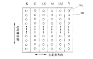
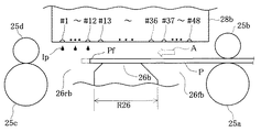
図21は、第3実施例における印刷ヘッド28bと上流側溝部26fbおよび下流側溝部26rbの関係を示す側面図である。ここでは、1列のノズル列が48個のノズルを有する印刷装置において上端処理および下端処理を行う場合について説明する。ここで使用する印刷装置では、下流側溝部26rbは、副走査方向について、ノズル#1〜#12と向かい合う位置に設けられる。また、上流側溝部26fbは、ノズル#37〜#48と向かい合う位置に設けられる。他の点はすでに説明した印刷装置と同様の構成である。
【0085】
図22は、第3実施例におけるインク吐出用ヘッド61b〜66bにおけるインクジェットノズルNzの配列を示す説明図である。この第3実施例では、各ノズルのピッチとラスタのピッチとは同一である。したがって、印刷ヘッド28bは、一度の主走査で隣り合うラスタにドットを記録することができる。図22においては、プラテン26b上の下流側溝部26rbと向かい合う範囲をRrで示し、上流側溝部26fbと向かい合う範囲をRfで示している。範囲Rrに存在するノズルはノズル#1〜#12であり、範囲Rfに存在するノズルは#37〜#48である。第3実施例では、この印刷ヘッド28bを用いてオーバーラップ印刷を行う。
【0086】
(1)第3実施例の上端処理:
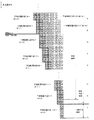
図23および図24は、第3実施例の上端処理において、各ラスタがどのノズルによってどのように記録されていくかを示す説明図である。図23の下部が、図24の上部につながる。なお、上から66番目から74番目までのラスタは、重複して記載されている。
【0087】
図23に示すように、第3実施例の上端処理においては、6ドットづつの副走査送りを10回繰り返す。この上端処理が、「第1の記録モード」における印刷である。この上端処理においては、印刷ヘッド28bの#1〜#12のノズル以外のノズルは使用されない。図において太枠で囲まれたノズルが、ラスタにドットを記録するノズルである。上端処理で使用されるノズルは、図22においてノズル群N1として示されるノズルである。
【0088】
その後、「移行処理」が行われる。この移行処理においては、上端処理のときと同じく6ドットの副走査送りが2回行われる。移行処理においては、最初の送りの後には、上端処理の場合と同じく#1〜#12ノズルでドットが記録される。そして、2回目の送りの後には、#1〜#30ノズルが使用される。その後、図24に示すように、中間処理に移行して、24ドットの定則送りが繰り返される。中間処理においては、#1〜#48のすべてのノズルが使用される。この中間処理が、「第2の記録モード」における印刷である。なお、移行処理の2回目の送りの後に使用されるノズルは、図22においてノズル群N2として示されるノズルである。そして、中間処理において使用されるノズルは、図22においてノズル群N3として示されるノズルである。
【0089】
図23において、最上段から6番目までのラスタについては、印刷の際の主走査においてノズルが1度しか通過しないため、オーバーラップ印刷を行うことができない。本実施例では、これら6本のラスタが「印刷不可領域」である。また、上から13番目以降のラスタのような、2以上のノズルが通過するラスタについては、最後にラスタを通過するノズル、およびその直前にラスタを通過するノズルのみがドットを記録するものとする。
【0090】
第3実施例では、印刷に使用する画像データDは、印刷可能領域の上端である、副走査方向上流の端から7番目のラスタから設定する。しかし、第1実施例と同様の理由から、印刷は、印刷用紙Pの上端が副走査方向上流の端から37番目のラスタの位置にあるときから開始する。その位置を図23において印刷用紙Pの上端の想定位置として示す。すなわち、第3実施例においては、想定される印刷用紙Pの上端の位置を越えて36ラスタ分だけ画像データDが設けられる。このため、印刷用紙Pの送りに誤差が生じて印刷用紙Pが余分に送られてしまっても、その誤差が36ラスタ分以内であれば、印刷用紙Pの上端まで余白なく画像を形成することができる。
【0091】
また、第3実施例においては、想定される印刷用紙Pの上端の位置を越えて設定される36ラスタ、および上端の位置からの42ラスタは、下流側溝部26rb上のノズル#1〜#12のみで記録される。よって、印刷用紙Pの上端の想定位置をこえて(すなわち、印刷用紙が存在しない範囲に)設定された、上述の36ラスタに対してインク滴を吐出しても、プラテン26a上にインク滴を着弾させてしまうことがない。また、印刷用紙Pの送りに誤差が生じて印刷用紙Pが想定位置まで送られなかった状態で、印刷用紙Pの上端部に割り当てられたラスタに対してインク滴を吐出しても、送りの誤差が42ラスタ分以内であれば、プラテン26b上にインク滴を着弾させてしまうことがない。
【0092】
(2)第3実施例の下端処理:
図25および図26は、第3実施例の下端処理において、各ラスタがどのノズルによってどのように記録されていくかを示す説明図である。図25の下部が、図26の上部につながる。
【0093】
本実施例では、図25に示すように、中間処理において24ドットの定則送りを繰り返したのち、移行処理において6ドットの送りを1回行う。その送りの後に使用されるノズルは、#19〜#48である。その後、下端処理において、ノズル#37〜#48のみを使用して6ドットの送りを行う。なお、移行処理の送りの後に使用されるノズルは、図22においてノズル群N4として示されるノズルである。そして、下端処理で使用されるノズルは、図22においてノズル群N5として示されるノズルである。
【0094】
なお、第3実施例では、図26に示すように、印刷ヘッド28上のノズルがドットを記録しうるラスタのうち、下から7番目以上のラスタ(印刷可能領域)を使用して画像を記録することができる。しかし、第3実施例では、下から9番目以上のラスタを使用して画像を記録する。すなわち、図26の下から9番目以上のラスタが印刷領域であり、それらのラスタに対して画像データが設定される。
【0095】
また、図26において、下から13番目以上のラスタは、印刷の際の主走査において2個以上のノズルが通過する。そのような、印刷において2以上のノズルが通過するラスタについては、最初にそのラスタ上を通過するノズル、およびその次にそのラスタを通過するノズルがドットを記録する。
【0096】
第3実施例では、印刷に使用する画像データDは、この下から9番目のラスタまで設定する。しかし、第1実施例と同様の理由から、印刷は、印刷用紙Pの下端が副走査方向下流の端から9番目の位置にあるときではなく、49番目のラスタの位置にあるときに終了する。印刷終了時の各ラスタに対する印刷用紙Pの下端の想定位置を、図26に示す。よって、第3実施例においては、想定される印刷用紙Pの下端の位置を越えて40ラスタ分だけ画像データDが設けられている。このため、印刷用紙Pの送りに誤差が生じて印刷用紙Pが想定位置まで送られなくても、その誤差が40ラスタ分以内であれば、下端まで余白なく画像を形成することができる。
【0097】
また、第3実施例においては、想定される印刷用紙Pの下端の位置を越えて設定される40ラスタ、および下端の位置から上流側の36ラスタは、上流側溝部26fb上のノズル#37〜#48のみで記録される。よって、印刷用紙Pの下端の想定位置をこえて(すなわち、印刷用紙が存在しない範囲に)設定されたラスタに対してインク滴を吐出しても、プラテン26b上にインク滴を着弾させてしまうことがない。また、印刷用紙Pの送りに誤差が生じて印刷用紙Pが余分に送られてしまった状態で、印刷用紙Pの下端部に割り当てられたラスタに対してインク滴を吐出しても、送りの誤差が36ラスタ分以内であれば、プラテン26a上にインク滴を着弾させてしまうことがない。
【0098】
なお、第3実施例においても、印刷用紙Pの下端部において上流側溝部26fb上のノズル(#37〜#48)のみによって記録されるラスタの数を、印刷用紙Pの上端部において下流側溝部26rb上のノズル(#1〜#12)のみによって記録されるラスタの数よりも多く設定している。そして、画像データDにおいて、印刷用紙Pの下端をこえて設定するラスタの数を、印刷用紙Pの上端をこえて設定するラスタの数よりも多く設定している。
【0099】
E.側方溝部を有する態様:
上記では、図7に示すように、プラテン26に上流側溝部26fと下流側溝部26rを有するプリンタ22において、印刷用紙Pの上下端を超えて設定される画像データD(図9参照)に基づいて、印刷を行う態様について説明した。ここでは、上流側溝部26f、下流側溝部26rに加えて左側溝部26na、右側溝部26nbをプラテンに有するプリンタ22nにおいて、印刷用紙Pの上下端および左右端を超えて設定される画像データDnに基づいて、印刷を行う態様について説明する。
【0100】
図27は、画像データDnと印刷用紙Pとの関係を示す平面図である。図27では、画像データDnは、印刷用紙Pの上端Pf、下端Prだけでなく、左側端Pa、右側端Pbをも超えて、印刷用紙Pの外側まで設定される。その結果、本実施例においては、画像データDnと印刷用紙Pの大きさ、及び印刷時の画像データDnの想定位置と印刷用紙Pの配置の関係は、図27に示すようになる。この画像データDnによって記録できる画像の幅(拡張領域の幅)は、印刷用紙Pの左右の端を超える幅を有し、かつ、左側溝部26naと右側溝部26nbの外側の側壁同士の間隔を超えない幅を有する。なお、左側端Pa、右側端Pbの左右の名称については、プリンタ22の左右の名称と対応させているため、印刷用紙Pにおいては、実際の左右と左側端Pa、右側端Pbの名称とが逆になっている。
【0101】
図28は、プリンタ22nのプラテン26nの周辺を示す平面図である。このプリンタ22nは、印刷用紙Pの副走査の際に、印刷用紙Pが主走査方向の所定の位置を保つようにガイドするガイド29a,29bを備えている。また、プラテン26nには、図7のプラテン26と同様に、上流側溝部26fと下流側溝部26rが設けられている。さらに、プラテン26nには、上流側溝部26fと下流側溝部26rとのそれぞれの両端を結ぶように副走査方向に延びる、左側溝部26naと右側溝部26nbとが設けられている。左側溝部26naと右側溝部26nbとは、印刷ヘッド上のノズル列からのインク滴の着弾範囲よりも長く副走査の方向の範囲に設けられている。そして、左側溝部26naと右側溝部26nbは、それぞれの中心線同士の(主走査方向の)間隔が、印刷用紙Pの主走査方向の幅に等しくなるように設けられている。他の構成は上述のプリンタ22と同様である。
【0102】
なお、左側溝部26naと右側溝部26nbは、印刷用紙Pがガイド29a,29bによってガイドされる所定の主走査位置にあるとき、印刷用紙Pの主走査の方向の一方の側端部Paが左側溝部26naの開口上に位置し、他方の側端部Pbが右側溝部26nbの開口上に位置するように設けられていればよい。したがって、左側溝部26naと右側溝部26nbは、上記のように、印刷用紙Pが定位置にあるとき、その側端部が左側溝部26naと右側溝部26nbの中心線上にある態様以外に、印刷用紙Pの側端部が左側溝部26naと右側溝部26nbの中心線よりも内側や外側に位置するように設けられていてもよい。
【0103】
これら上流側溝部26f、下流側溝部26r、左側溝部26naおよび右側溝部26nbは互いに接続されており、四辺形の溝部を構成する。そして、その底部にはインク滴Ipを受けてこれを吸収するための吸収部材27が配されている。
【0104】
印刷用紙Pは、上流側紙送りローラ25a、25bおよび下流側紙送りローラ25c、25dによって副走査送りを実施されているときには、上流側溝部26fと下流側溝部26rの開口上を通過していく。また、印刷用紙Pは、プラテン26n上において、左側端部Paは左側溝部26na上に位置し、右側端部Pbは右側溝部26nb上に位置するように、ガイド29a,29bによって主走査方向について位置決めされている。よって、副走査送りの際には、印刷用紙Pの両側端がそれぞれ左側溝部26na、右側溝部26nbの開口上にある位置を保って送りがなされる。
【0105】
図28の態様においても、上端処理および下端処理の副走査の送りについては、ノズル列の各ノズルとプラテン26nとの相対位置関係に応じて、前述の第1ないし第3実施例の送りを行うことができる。したがって、以下では、印刷用紙Pの側端部Pa,Pbの印刷について説明する。
【0106】
図29は、印刷用紙Pの左右側端部の印刷を示す説明図である。図28の態様では、上端処理および下端処理を含め、印刷用紙Pへの画像の記録全体を通じて、印刷用紙Pの左右端部にも余白を設けないように印刷を行う。その際、印刷ヘッド28は、主走査において、一方の端については、全てのノズルが印刷用紙Pの端を越えて印刷用紙Pの外側に位置するところまで送られ、他方の端についても、やはり全てのノズルが印刷用紙Pの他方の端を越えて印刷用紙Pの外側に位置するところまで送られる。そして、ノズルNzが印刷用紙P上にあるときだけでなく、ノズルNzが印刷用紙Pの端を超えた位置であって、かつ、左側溝部26naまたは右側溝部26nb上にあるときにも、画像データDnにしたがってそのノズルNzからインク滴を吐出する。なお、画像データDnの画像領域(拡張領域)は、印刷用紙Pの左右の端を超える幅を有し、かつ、左側溝部26naと右側溝部26nbの外側の側壁同士の間隔を超えない幅を有する。このため、ノズルが印刷用紙Pの外側で左側溝部26naまたは右側溝部26nb上にあるときにも、画像データDnにしたがってインク滴を吐出することができる。
【0107】
このような印刷を行うことで、多少印刷用紙Pが主走査方向に多少ずれた場合にも、印刷用紙Pの左右の両端に余白を作ることなく画像を形成することができる。そして、印刷用紙の両側端部を印刷するノズルは左側溝部26naまたは右側溝部26nb上に位置するノズルであるため、インク滴が印刷用紙Pからはずれた場合にも、インク滴はプラテン26の中央部26cに着弾することなく、左側溝部26naまたは右側溝部26nbに着弾する。よって、プラテン26の中央部26cに着弾したインク滴によって、印刷用紙Pが汚されることがない。
【0108】
F.変形例:
なお、この発明は上記の実施例や実施形態に限られるものではなく、その要旨を逸脱しない範囲において種々の態様において実施することが可能であり、例えば次のような変形も可能である。
【0109】
F1.変形例1:
第1実施例では、上端処理と下端処理では1ドットづつの定則送りを行い、第2実施例では3ドットづつ、第3実施例では6ドットづつの送りの定則送りを行った。しかし、上端処理と下端処理の送りはこれに限られるものではなく、ノズル列中のノズル数やノズルピッチに応じて、2ドットや4ドット、5ドットの定則送りとすることもできる。すなわち、最大の副走査送り量が中間処理における最大の副走査送り量よりも小さいものであれば、どのような送りであってもよい。ただし、上端処理の副走査送りの送り量が小さいほど、より副走査方向の下流側のノズルで印刷用紙の上端を記録することができる。そのため、より下流側溝部を狭くすることができ、印刷用紙を支えるプラテン上面を広く取ることができる。同様に、下端処理の副走査送りの送り量が小さいほど、より上流側のノズルで印刷用紙の上端を記録することができる。そのため、より上流側溝部を狭くすることができ、印刷用紙を支えるプラテン上面を広く取ることができる。
【0110】
また、中間処理における送りも、5ドット、2ドット、3ドット、6ドットの送りをその順に繰り返す変則送りや、11ドットの定則送り、24ドットの定則送りに限られるものではない。例えば、第1実施例に示した構成において、5ドット、3ドット、2ドット、6ドット送りとしてもよい。また、ノズル数、ノズルピッチなどに応じて他の送り量の組み合わせを採用することもでき、他の送り量の定則送りを実施することとしてもよい。すなわち、最大の副走査送り量が上端処理か下端端処理における最大の副走査送り量よりも大きいものであれば、どのような副走査送りを行ってもよい。
【0111】
F2.変形例2:
上記実施例では、印刷用紙の端を超えて設定される画像は、第1実施例においては上端側および下端側とも2ラスタ分であり、第2実施例においては上端側が16ラスタ、下端側が30ラスタであった。そして、第3実施例では、上端側が30ラスタ、下端側が40ラスタであった。しかし、印刷用紙の端を超えて設定される画像の大きさは、これに限られるものではない。例えば、印刷用紙Pの上端Pfを超えて印刷用紙Pの外側ま設定する画像データDの部分の幅は、下流側溝部26rの幅の1/2相当分とすることができる。同様に、印刷用紙Pの下端Prを超えて印刷用紙Pの外側ま設定する画像データDの部分の幅は、上流側溝部26fの幅の1/2相当分とすることができる。すなわち、印刷用紙の端を超えて印刷用紙の外側まで設定する画像データの部分の幅は、上端側については、下流側溝部26rの幅よりも小さければよく、下端側については、上流側溝部26fの幅よりも小さければよい。そのようにすれば、印刷用紙Pの端が想定した位置にない場合にも、印刷用紙Pを超えて設定した画像を記録するためのインク滴Ipが、プラテン26上面に着弾してしまうことがない。ただし、溝部の幅の1/2とすれば、印刷用紙Pが上流側にずれる場合についても下流側にずれる場合についても、同程度のずれ量を許容することができる。
【0112】
同様に、左右の側端についても、印刷用紙の端を超えて印刷用紙の外側まで設定する画像データの部分の幅は、左側溝部26naや右側溝部26nbについても、の幅よりも小さければよい。そして、溝部の幅の1/2とすれば、印刷用紙Pが上流側にずれる場合についても下流側にずれる場合についても、同程度のずれ量を許容することができる。
【0113】
F3.変形例3:
上記実施例では、上端処理と下端処理の両方を実行していたが、必要に応じていずれか一方のみを実行するようにしてもよい。また、本実施例の印刷装置は、プラテン26の、副走査方向の上流側および下流側にそれぞれ上流側溝部26fと下流側溝部26rを備えていたが、いずれか一方のみを備えるものとしてもよい。
【0114】
F4.変形例4:
上記実施例において、ハードウェアによって実現されていた構成の一部をソフトウェアに置き換えるようにしてもよく、逆に、ソフトウェアによって実現されていた構成の一部をハードウェアに置き換えるようにしてもよい。例えば、CPU41(図5)の機能の一部をホストコンピュータ90が実行するようにすることもできる。
【0115】
このような機能を実現するコンピュータプログラムは、フロッピディスクやCD−ROM等の、コンピュータ読み取り可能な記録媒体に記録された形態で提供される。ホストコンピュータ90は、その記録媒体からコンピュータプログラムを読み取って内部記憶装置または外部記憶装置に転送する。あるいは、通信経路を介してプログラム供給装置からホストコンピュータ90にコンピュータプログラムを供給するようにしてもよい。コンピュータプログラムの機能を実現する時には、内部記憶装置に格納されたコンピュータプログラムがホストコンピュータ90のマイクロプロセッサによって実行される。また、記録媒体に記録されたコンピュータプログラムをホストコンピュータ90が直接実行するようにしてもよい。
【0116】
この明細書において、ホストコンピュータ90とは、ハードウェア装置とオペレーションシステムとを含む概念であり、オペレーションシステムの制御の下で動作するハードウェア装置を意味している。コンピュータプログラムは、このようなホストコンピュータ90に、上述の各部の機能を実現させる。なお、上述の機能の一部は、アプリケーションプログラムでなく、オペレーションシステムによって実現されていても良い。
【0117】
なお、この発明において、「コンピュータ読み取り可能な記録媒体」とは、フレキシブルディスクやCD−ROMのような携帯型の記録媒体に限らず、各種のRAMやROM等のコンピュータ内の内部記憶装置や、ハードディスク等のコンピュータに固定されている外部記憶装置も含んでいる。
【図面の簡単な説明】
【図1】本発明の実施の形態におけるインクジェットプリンタの印刷ヘッドの周辺の構造を示す側面図。
【図2】印刷用紙Pの後端Prにおける印刷の様子を示す説明図である。
【図3】本発明の実施例としての画像処理装置および印刷装置の構成を示すブロック図。
【図4】本印刷装置のソフトウェアの構成を示すブロック図。
【図5】本印刷装置の機械部分の構成を示す図。
【図6】印刷ヘッドユニット60における各色ごとのノズルユニットの配列の例を示す平面図。
【図7】プラテン26の周辺を示す平面図。
【図8】印刷用紙の上端(先端)近傍において、各ラスタがどのノズルによってどのように記録されていくかを示す説明図。
【図9】画像データDと印刷用紙Pとの関係を示す平面図。
【図10】印刷開始時の印刷ヘッド28と印刷用紙Pの関係を示す側面図。
【図11】比較例における印刷開始時の印刷ヘッド28と印刷用紙Pの関係を示す側面図。
【図12】下端処理において、各ラスタがどのノズルによってどのように記録されていくかを示す説明図。
【図13】印刷用紙Pの下端部Prの印刷をする際の上流側溝部26fと印刷用紙Pの関係を示す平面図。
【図14】印刷用紙の最下端の印刷をする際の印刷ヘッド28と印刷用紙Pの関係を示す側面図。
【図15】比較例における印刷用紙の最下端の印刷をする際の印刷ヘッド28と印刷用紙Pの関係を示す側面図。
【図16】第2実施例における印刷ヘッド28aと上流側溝部26faおよび下流側溝部26raの関係を示す側面図。
【図17】第2実施例の上端処理において、各ラスタがどのノズルによってどのように記録されていくかを示す説明図。
【図18】第2実施例の上端処理において、各ラスタがどのノズルによってどのように記録されていくかを示す説明図。
【図19】第2実施例の下端処理において、各ラスタがどのノズルによってどのように記録されていくかを示す説明図。
【図20】第2実施例の下端処理において、各ラスタがどのノズルによってどのように記録されていくかを示す説明図。
【図21】第3実施例における印刷ヘッド28bと上流側溝部26fbおよび下流側溝部26rbの関係を示す側面図。
【図22】第3実施例におけるインク吐出用ヘッド61b〜66bにおけるインクジェットノズルNzの配列を示す説明図。
【図23】第3実施例の上端処理において、各ラスタがどのノズルによってどのように記録されていくかを示す説明図。
【図24】第3実施例の上端処理において、各ラスタがどのノズルによってどのように記録されていくかを示す説明図。
【図25】第3実施例の下端処理において、各ラスタがどのノズルによってどのように記録されていくかを示す説明図。
【図26】第3実施例の下端処理において、各ラスタがどのノズルによってどのように記録されていくかを示す説明図。
【図27】画像データDnと印刷用紙Pとの関係を示す平面図。
【図28】プリンタ22nのプラテン26nの周辺を示す平面図。
【図29】印刷用紙Pの左右側端部の印刷を示す説明図。
【図30】従来のプリンタの印刷ヘッドの周辺を示す側面図。[0001]
TECHNICAL FIELD OF THE INVENTION
The present invention relates to a technique for recording dots on the surface of a recording medium using a dot recording head, and more particularly to a technique for performing printing up to the edge of a printing sheet without soiling a platen.
[0002]
[Prior art]
In recent years, printers that eject ink from nozzles of a print head have become widespread as output devices of computers. FIG. 30 is a side view showing the periphery of a print head of a conventional printer. The printing paper P is supported on the platen 26o so as to face the head 28o. The printing paper P is supplied to the upstream
[0003]
[Problems to be solved by the invention]
When trying to print an image to the edge of the printing paper in the printer as described above, it is necessary to arrange the printing paper so that the edge of the printing paper is located below the printing head, that is, on the platen, and eject ink droplets from the printing head. There is. However, in such printing, due to an error in the feeding of the printing paper or a shift in the landing position of the ink droplet, the ink droplet may deviate from the end of the printing paper where it should originally land and land on the platen. . In such a case, the printing paper that subsequently passes on the platen is stained by the ink that has landed on the platen.
[0004]
SUMMARY OF THE INVENTION The present invention has been made to solve the above-described problem in the related art, and an object of the present invention is to provide a technique for performing printing up to the end of a printing sheet without causing ink drops to land on a platen.
[0005]
[Means for Solving the Problems and Their Functions and Effects]
In order to solve at least a part of the above problems, the present invention provides a dot recording apparatus that records dots on the surface of a print medium using a dot recording head provided with a plurality of dot forming elements that eject ink droplets. As a target, a predetermined process is performed. The dot recording apparatus is provided extending in the main scanning direction so as to face the dot forming element in at least a part of the path of the main scanning, supports the printing medium so as to face the dot recording head, and includes a plurality of dots. Of the forming elements Some of A platen having a groove extending in the main scanning direction at a position facing the dot forming element is provided.
[0006]
Printing (dot recording) performed in such a printing apparatus is performed by driving at least one of the dot forming elements while driving at least one of the dot recording head and the print medium to perform main scanning. This is dot recording in which dots are formed and a sub-scan is performed by driving the print medium in a direction intersecting with the direction of the main scan between main scans. At that time, in the vicinity of the end of the print medium, while printing dots in the first print mode, the print medium is supported by the platen, and when the upper end or lower end of the print medium is over the opening of the groove, Edge printing is performed in which ink droplets are ejected from at least a part of the dot forming element located at a position facing the groove to form a dot on a print medium. Then, in the middle portion of the print medium, dots are recorded in the second recording mode in which the maximum sub-scanning feed amount is larger than the maximum sub-scanning feed amount in the first recording mode.
[0007]
According to this aspect, it is possible to print without margins up to the end of the printing paper without causing ink droplets to land on the platen using the dot forming element located at the position facing the groove.
[0008]
When performing edge printing, it is preferable that ink droplets are not ejected from dot forming elements other than the dot forming element located at a position facing the groove. According to such an embodiment, in the printing of the upper end of the print medium, the feed amount of the sub-scan of the print medium up to that time is insufficient, and the upper end does not reach the groove, that is, the upper end of the print medium is the platen. Even when the platen is located above and a part of the platen is directly opposed to the dot recording head, the platen is not stained by the ink droplets. The same applies to the case where the sub-scan feed amount of the print medium is excessive in printing the lower end of the print medium and the lower end of the print medium has passed over the groove.
[0009]
When the groove is provided at a position facing the dot forming element located at least at the downstream end in the sub-scanning direction of the plurality of dot forming elements, when the upper end of the print medium is over the opening of the groove, Preferably, edge printing is performed. With such an embodiment, an image can be recorded at the upper end of the print medium without any blank space.
[0010]
When the groove is provided at a position facing the dot forming element located at least at the upstream end in the sub-scanning direction among the plurality of dot forming elements, when the lower end of the printing medium is above the opening of the groove. It is preferable to carry out edge printing. With such an embodiment, an image can be recorded at the lower end of the print medium without any blank space.
[0011]
A sub-scanning drive unit for performing sub-scanning in the printing apparatus is provided on the upstream side in the sub-scanning direction with respect to the dot recording head, and is an upstream sub-scanning drive that holds the printing medium and drives the printing medium. And a downstream sub-scanning drive unit provided on the downstream side in the sub-scanning direction with respect to the dot recording head and holding the print medium and driving the print medium. Dot recording has the following advantages.
[0012]
In the printing apparatus as described above, when printing the end portion of the print medium, the sub-scan must be performed by only one of the upstream sub-scan drive unit and the downstream sub-scan drive unit. In such a printing apparatus, by performing printing as described above, it is possible to shorten the distance for performing printing by performing sub-scanning with only one of the upstream sub-scanning driving unit and the downstream sub-scanning driving unit.
[0013]
It is preferable that the sub-scan feed performed in the first recording mode is a sub-scan feed in units of one dot. In this way, the end of the print medium can be recorded by the nozzle near the end in the sub-scanning direction in the dot recording head.
[0014]
In the printing as described above, an image to be recorded is generated on a print medium to generate image data set outside the print medium beyond the end where the edge printing is performed, and the image is printed. It is preferable to form dots based on the data. In this way, even when there is a positioning error of the print medium, printing can be performed on a portion of the print medium that deviates from the expected position based on the image set outside the print medium.
[0015]
Further, in the image data, it is preferable that a dimension of a portion of the image that exceeds the edge where the edge printing of the print medium is performed is set to be smaller than the width of the groove. By doing so, even if the ink droplets for recording the portion set beyond the edge where the edge printing of the print medium is performed do not land on the print medium, those ink droplets are also used. The print medium can be positioned with respect to the dot recording head so that the ink droplet lands in the groove.
[0016]
The present invention can be realized in various modes as described below.
(1) Dot recording method, printing control method, printing method.
(2) Dot recording device, print control device, printing device.
(3) Computer programs for realizing the above devices and methods.
(4) A recording medium on which a computer program for realizing the above apparatus and method is recorded.
(5) A data signal embodied in a carrier wave, including a computer program for realizing the above apparatus and method.
[0017]
BEST MODE FOR CARRYING OUT THE INVENTION
Hereinafter, embodiments of the present invention will be described in the following order based on examples.
A. Overview of the embodiment:
B. First embodiment:
C. Second embodiment:
D. Third embodiment:
E. FIG. Embodiment having side grooves:
F. Modification:
[0018]
A. Overview of the embodiment:
FIG. 1 is a side view showing a structure around a print head of an inkjet printer according to an embodiment of the present invention. In FIG. 1, the printing paper P is held and fed by the upstream
[0019]
When printing near the front end Pf of the printing paper P, it is preferable to perform printing by repeating a minute sub-scan feed having a feed amount of 1 dot. By doing so, it becomes easy to print the front end portion of the printing paper on the
[0020]
FIG. 2 shows the printing paper P rear The state of printing at the end Pr is shown. In FIG. 2, at the final stage of printing, the printing paper P is being held and fed only by the downstream
[0021]
Even when printing near the rear end Pr of the printing paper, it is preferable to repeat the minute sub-scan feed to perform printing. By doing so, it becomes easy to print the rear end portion of the printing paper on the
[0022]
B. First embodiment:
(1) Configuration of device:
FIG. 3 is a block diagram illustrating a configuration of an image processing apparatus and a printing apparatus according to an embodiment of the present invention. As shown in the figure, the
[0023]
In addition, a serial input / output interface (SIO) 88 is connected to the
[0024]
FIG. 4 is a block diagram illustrating a software configuration of the printing apparatus. In the
[0025]
When the
[0026]
The
[0027]
The color-corrected data has a gradation value with a width of, for example, 256 gradations. The
[0028]
Next, a schematic configuration of the
[0029]
The mechanism for reciprocating the
[0030]
The
[0031]
The heads 61 to 66 of each color provided at the lower portion of the
[0032]
FIG. 6 is an explanatory diagram showing the arrangement of the inkjet nozzles Nz in the ink ejection heads 61 to 66. These nozzles are arranged from six nozzle arrays that eject ink for each color of black (K), cyan (C), light cyan (LC), magenta (M), light magenta (LM), and yellow (Y). 48 nozzles are arranged in a row at a constant nozzle pitch k. The “nozzle pitch” is a value indicating how many rasters (that is, how many pixels) the intervals of the nozzles arranged on the print head in the sub-scanning direction are. For example, the pitch k of the nozzles arranged at intervals of three rasters is four.
[0033]
FIG. 7 is a plan view showing the periphery of the
[0034]
The
[0035]
The
[0036]
Next, the internal configuration of the control circuit 40 (see FIG. 5) of the
[0037]
In the
[0038]
In the printer of this embodiment, the upper end Pf of the printing paper P is printed on the
[0039]
The width W of the
[0040]
W = p × n + α
[0041]
Here, p is a feed amount [inch] of one sub-scan feed in the upper / lower edge processing. n is the number of sub-scan feeds performed in each of the upper end processing and the lower end processing. α is a sub-scan feed error assumed in each of the upper end processing and the lower end processing. It is preferable that the value of α in the lower end process (
[0042]
(2) Sub-scan feed:
(I) Upper end processing of the first embodiment:
FIG. 8 is an explanatory diagram showing how each raster is recorded by which nozzle near the upper end (front end) of the printing paper. Here, for simplicity, the description will be made using only one nozzle row. It is assumed that one nozzle row has eight nozzles. At the time of main scanning, each nozzle is responsible for recording one raster. Here, the “raster” is a row of pixels arranged in the main scanning direction. The “pixel” is a square grid virtually defined on a print medium in order to define a position where an ink droplet lands and a dot is recorded. Here, it is assumed that the nozzles are arranged at intervals of three rasters.
[0043]
In FIG. 8, one row of cells arranged vertically represents the
[0044]
Thereafter, the process proceeds to the intermediate processing, and the feeding of 5, 2, 3, and 6 dots is repeated in that order. This intermediate processing is "Second recording mode" Printing. A method of performing sub-scanning by combining different feed amounts in this manner is called “irregular feed”. When the above-described sub-scan feed is performed, each raster is recorded by two nozzles except for some rasters. That is, in this embodiment, each raster is printed by two nozzles. For example, in FIG. 8, the fifth raster from the top is recorded by
[0045]
On the other hand, in FIG. 8, the four rasters from the top row only pass the
[0046]
In FIG. 8, three nozzles pass through the thirteenth and fifteenth rasters from the top in the main scan during printing. In such a raster in which three or more nozzles pass during printing, it is assumed that only two of the nozzles record dots. It is preferable that these rasters are recorded by nozzles passing over the rasters after shifting to intermediate processing as much as possible. In the intermediate processing, irregular feeding is performed, and the combination of nozzles passing on adjacent rasters is different. Therefore, compared to the upper end processing in which regular feeding is performed one dot at a time, the print result is high in image quality. It is because it can be expected to become.
[0047]
In this embodiment, an image is recorded without a margin up to the upper end of the printing paper. As described above, in the present embodiment, among the rasters on which the nozzles on the
[0048]
FIG. 9 is a plan view showing the relationship between the image data D and the printing paper P. As described above, in this embodiment, the image data D is set beyond the upper end Pf of the printing paper P to the outside of the printing paper P. Also, for the lower end side, the image data D is set beyond the lower end Pr of the printing paper P to the outside of the printing paper P for the same reason. Therefore, in the present embodiment, the relationship between the size of the image data D and the printing paper P and the relationship between the arrangement of the image data D and the printing paper P during printing are as shown in FIG. In the present embodiment, the width of the portion of the image data D set beyond the upper end Pf of the printing paper P to the outside of the printing paper P is two rasters. Similarly, the width of the portion of the image data D set beyond the lower end Pr of the printing paper P to the outside of the printing paper P is also equivalent to two rasters. In this specification, the terms “upper end (part)” and “lower end (part)” are used to refer to the edges of the printing paper P in correspondence with the top and bottom of the image data recorded on the printing paper P, When referring to the edge of the printing paper P in correspondence with the traveling direction of the sub-scanning feed of the printing paper P on the
[0049]
FIG. 10 is a side view showing the relationship between the
[0050]
In FIG. 7, the nozzle group Nr in the shaded portion of the
[0051]
As described above, at the start of printing, the upper end Pf of the printing paper P is at the position of the seventh raster from the upstream end in the sub-scanning direction among the rasters on which the nozzles on the
[0052]
However, when the printing paper P is sent for a reason more than the original feed amount, the upper end of the printing paper P is placed on the second raster from the top of the printable area or the uppermost row of the printable area. May come to the raster position. In this embodiment, even in such a case, since the
[0053]
Conversely, for some reason, the printing paper P may be sent less than the original feed amount. In such a case, there is no printing paper at the position where the printing paper should be, and the ink droplet Ip lands on the structure below. However, as shown in FIG. 8, in this embodiment, two rasters from the assumed upper end position of the paper are recorded by
[0054]
The printing paper P is preferably held by two pairs of upstream
[0055]
Further, when printing the upper end portion, the printing paper P is supported at two places: the upstream
[0056]
(Ii) Top feed of comparative example:
FIG. 11 is a side view showing the relationship between the
[0057]
When printing the upper end portion, the printing paper P is held only by the upstream
[0058]
(Iii) Lower end processing of the first embodiment:
FIG. 12 is an explanatory diagram showing how each raster is recorded by which nozzle in the lower end process. FIG. 12 shows a portion from the point at which the (n + 1) -th sub-scan feed is performed to the point at which the last (n + 17) -th sub-scan feed is performed. In the present embodiment, as shown in FIG. 12, in the intermediate processing, the feeding of 5 dots, 2 dots, 3 dots, and 6 dots is repeated in that order in the sub-scanning feed up to the (n + 8) -th time, and then the lower 9 Times, that is, the (n + 9) -th to (n + 17) -th sub-scan feeds are performed by one-dot feed. As a result, each raster along the main scanning direction is recorded by two nozzles, except for some rasters. Note that in FIG. 12, the rasters on which the nozzles on the
[0059]
In FIG. 12, the four rasters from the bottom row only pass the
[0060]
In FIG. 12, three or more nozzles pass through the ninth and tenth rasters from the bottom in the main scan at the time of printing. With respect to such a raster through which three or more nozzles pass in printing, it is preferable to record by a nozzle passing on the raster in the intermediate processing as much as possible. This is because the print result can be expected to have high image quality as compared with the lower end process in which the regular feed is performed dot by dot.
[0061]
In this embodiment, as in the case of the upper end, an image is recorded without margins at the lower end. As described above, in the present embodiment, among the rasters on which the nozzles on the
[0062]
FIG. 13 is a plan view showing the relationship between the
[0063]
FIG. 14 is a side view showing the relationship between the
[0064]
Also, even if the printing paper P is sent for a reason less than the original feeding amount, the
[0065]
And the assumption of paper lower end The two rasters above the position (the seventh and eighth rasters from the bottom in FIG. 12) are to be recorded by
[0066]
In the present embodiment, the position of the seventh raster from the downstream end in the sub-scanning direction among the rasters on which the nozzles on the
[0067]
Further, when printing the lower end portion, the printing paper P is supported at two places: the downstream
[0068]
(Iv) Lower end feed of comparative example:
FIG. 15 is a side view illustrating a relationship between the
[0069]
When printing the lower end portion, the printing paper P is held only by the downstream
[0070]
C. Second embodiment:
FIG. 16 is a side view showing the relationship between the
[0071]
(1) Upper end processing of the second embodiment:
17 and 18 are explanatory diagrams showing how each raster is recorded by which nozzle in the upper end process of the second embodiment. FIGS. 17 and 18 show the manner in which the head records a raster, divided into upper and lower parts. The lower part of FIG. 17 is connected to the upper part of FIG. Note that the 38th to 42nd rasters from the top are duplicated in FIGS. 17 and 18.
[0072]
As shown in FIG. 17, in the upper end process of the second embodiment, the sub-scan feed of three dots is repeated 11 times. This upper end processing "First recording mode" Printing. In this upper end processing, nozzles other than the
[0073]
After that, instead of performing the intermediate processing immediately, “migration processing” is performed before performing the intermediate processing. In this transition processing, the sub-scan feed of three dots is performed four times as in the upper end processing. In the transition process, all
[0074]
In FIG. 17, nozzles do not pass through the second, third, and sixth rasters from the top in the main scan during printing. Therefore, for the sixth raster from the top, pixels cannot be printed consecutively on adjacent rasters. In the present embodiment, these six rasters are “non-printable areas”. Also, for a raster such as the thirteenth or sixteenth raster from the top, which passes through two or more nozzles, only the nozzle that last passes through the raster records dots.
[0075]
In the second embodiment, among the rasters on which the nozzles on the
[0076]
In the second embodiment, 16 rasters set beyond the assumed upper end position of the printing paper P and 20 rasters from the upper end position are recorded only by the
[0077]
(2) Lower end processing of the second embodiment:
FIGS. 19 and 20 are explanatory diagrams showing how each raster is recorded by which nozzle in the lower end processing of the second embodiment. FIG. 19 shows the (n + 1) th and subsequent sub-scan feeds. FIGS. 19 and 20 show the manner in which the head records a raster, divided into upper and lower parts. The lower part of FIG. 19 is connected to the upper part of FIG. Note that the 45th to 40th rasters from the bottom are duplicated in FIGS. 19 and 20.
[0078]
In the present embodiment, as shown in FIGS. 19 and 20, in the intermediate processing, the regular scanning of 11 dots is repeated in the (n + 1) -th to (n + 3) th sub-scanning transmissions, and then the 3-dot feeding is repeated four times in the transition processing. . Then, thereafter, in the lower end processing, three dots are fed using only the
[0079]
In the second embodiment, as shown in FIG. 20, among the rasters on which the nozzles on the
[0080]
Also, in FIG. 20, the 13th and 16th rasters from the bottom pass through two or more nozzles in the main scan during printing. For such a raster in which two or more nozzles pass in printing, the nozzle that first passes on the raster records dots.
[0081]
In the second embodiment, an image can be recorded using the eighth or more rasters from the downstream end in the sub-scanning direction among the rasters on which the nozzles on the
[0082]
Further, in the second embodiment, 30 rasters set beyond the assumed lower end position of the printing paper P and 20 rasters upstream from the lower end position are recorded only by the
[0083]
When recording the lower end of the printing paper P, the printing paper P is sent a longer distance than when recording the upper end of the printing paper P. Therefore, when recording the lower end of the printing paper P, there is a high possibility that the error in the position of the printing paper P is larger than when recording the upper end of the printing paper P. The downstream
[0084]
D. Third embodiment:
FIG. 21 is a side view showing the relationship between the
[0085]
FIG. 22 is an explanatory diagram showing the arrangement of the inkjet nozzles Nz in the ink ejection heads 61b to 66b in the third embodiment. In the third embodiment, the pitch of each nozzle is equal to the pitch of the raster. Therefore, the
[0086]
(1) Upper end processing of the third embodiment:
FIGS. 23 and 24 are explanatory diagrams showing how each raster is recorded by which nozzle in the upper end processing of the third embodiment. The lower part of FIG. 23 is connected to the upper part of FIG. Note that the 66th to 74th rasters from the top are redundantly described.
[0087]
As shown in FIG. 23, in the upper end processing of the third embodiment, the sub-scan feed of 6 dots is repeated 10 times. This upper end processing "First recording mode" Printing. In this upper end processing, nozzles other than the
[0088]
After that, “migration processing” is performed. In this transition processing, the sub-scan feed of 6 dots is performed twice as in the upper end processing. In the transition process, after the first feed, dots are recorded by
[0089]
In FIG. 23, for the rasters from the top to the sixth, overlap printing cannot be performed because the nozzles pass only once in the main scan during printing. In the present embodiment, these six rasters are “non-printable areas”. In addition, for a raster that passes through two or more nozzles, such as the 13th and subsequent rasters from the top, only the nozzle that passes through the last raster and the nozzle that passes through the raster immediately before that record dots. .
[0090]
In the third embodiment, the image data D used for printing is set from the uppermost end of the printable area, ie, the seventh raster from the upstream end in the sub-scanning direction. However, for the same reason as in the first embodiment, printing starts when the upper end of the printing paper P is at the 37th raster position from the upstream end in the sub-scanning direction. The position is shown as an assumed position of the upper end of the printing paper P in FIG. That is, in the third embodiment, the image data D is provided for 36 rasters beyond the assumed upper end position of the printing paper P. Therefore, even if an error occurs in the feeding of the printing paper P and the printing paper P is excessively fed, if the error is within 36 rasters, it is necessary to form an image up to the upper end of the printing paper P without any margin. Can be.
[0091]
Further, in the third embodiment, 36 rasters set beyond the assumed upper end position of the printing paper P and 42 rasters from the upper end position are
[0092]
(2) Lower end processing of the third embodiment:
FIGS. 25 and 26 are explanatory diagrams showing how each raster is recorded by which nozzle in the lower end processing of the third embodiment. The lower part of FIG. 25 is connected to the upper part of FIG.
[0093]
In the present embodiment, as shown in FIG. 25, after regular 24 dot feeding is repeated in the intermediate processing, 6 dot feeding is performed once in the transition processing. The nozzles used after the feed are # 19 to # 48. Thereafter, in the lower end processing, six dots are fed using only the
[0094]
In the third embodiment, as shown in FIG. 26, among the rasters on which the nozzles on the
[0095]
In FIG. 26, the thirteenth or more rasters from the bottom are passed by two or more nozzles in the main scan during printing. For such a raster in which two or more nozzles pass in printing, the nozzle that first passes over the raster and the nozzle that subsequently passes through the raster record dots.
[0096]
In the third embodiment, the image data D used for printing is set up to the ninth raster from the bottom. However, for the same reason as in the first embodiment, printing ends when the lower end of the printing paper P is not at the ninth position from the downstream end in the sub-scanning direction but at the 49th raster position. . FIG. 26 shows the assumed position of the lower end of the printing paper P with respect to each raster at the end of printing. Therefore, in the third embodiment, the image data D is provided for 40 rasters beyond the assumed lower end position of the printing paper P. For this reason, even if an error occurs in the feeding of the printing paper P and the printing paper P is not sent to the expected position, if the error is within 40 rasters, it is possible to form an image with no blank space at the lower end.
[0097]
Further, in the third embodiment, 40 rasters set beyond the assumed lower end position of the printing paper P and 36 rasters upstream from the lower end position are nozzles # 37 to # 37 on the upstream groove portion 26fb. Recorded only in # 48. Therefore, even if an ink droplet is ejected to a raster set beyond the assumed position of the lower end of the printing paper P (that is, in a range where the printing paper does not exist), the ink droplet lands on the
[0098]
Also in the third embodiment, the number of rasters recorded by only the nozzles (# 37 to # 48) on the upstream groove 26fb at the lower end of the printing paper P is determined by the downstream groove at the upper end of the printing paper P. The number is set to be larger than the number of rasters recorded by only the nozzles (# 1 to # 12) on 26 rb. In the image data D, the number of rasters set above the lower end of the printing paper P is set larger than the number of rasters set above the upper end of the printing paper P.
[0099]
E. FIG. Embodiment having side grooves:
In the above description, as shown in FIG. 7, in the
[0100]
FIG. 27 is a plan view showing the relationship between the image data Dn and the printing paper P. In FIG. 27, the image data Dn is set not only to the upper end Pf and the lower end Pr of the printing paper P but also to the outside of the printing paper P beyond the left end Pa and the right end Pb. As a result, in this embodiment, the relationship between the size of the image data Dn and the printing paper P, and the relationship between the assumed position of the image data Dn and the arrangement of the printing paper P during printing is as shown in FIG. The width of the image that can be recorded by the image data Dn (the width of the extended area) has a width that exceeds the left and right ends of the printing paper P, and exceeds the interval between the outer side walls of the left groove 26na and the right groove 26nb. With no width. Since the left and right names of the left end Pa and the right end Pb correspond to the left and right names of the
[0101]
FIG. 28 is a plan view showing the periphery of the
[0102]
When the printing paper P is at a predetermined main scanning position guided by the
[0103]
The
[0104]
When the sub-scanning feed is being performed by the upstream
[0105]
In the embodiment of FIG. 28 as well, in the sub-scan feed of the upper end process and the lower end process, the feed of the above-described first to third embodiments is performed according to the relative positional relationship between each nozzle of the nozzle row and the
[0106]
FIG. 29 is an explanatory diagram illustrating printing on the left and right end portions of the printing paper P. In the mode of FIG. 28, printing is performed so that no margin is provided at the left and right ends of the printing paper P throughout the recording of the image on the printing paper P, including the upper end processing and the lower end processing. At that time, in the main scanning, the
[0107]
By performing such printing, even when the printing paper P slightly shifts in the main scanning direction, it is possible to form an image without creating margins on both left and right ends of the printing paper P. Since the nozzles that print both side edges of the printing paper are nozzles located on the left groove 26na or the right groove 26nb, even when the ink drops come off the printing paper P, the ink drops remain in the center of the
[0108]
F. Modification:
It should be noted that the present invention is not limited to the above-described examples and embodiments, and can be carried out in various modes without departing from the scope of the invention, and for example, the following modifications are possible.
[0109]
F1.
In the first embodiment, the regular feed of one dot is performed in the upper end process and the lower end process, and the regular feed of three dots is performed in the second embodiment, and the regular feed is performed in 6 dots in the third embodiment. However, the feed of the upper end process and the lower end process is not limited to this, and regular feed of 2 dots, 4 dots, and 5 dots can be performed according to the number of nozzles in the nozzle row and the nozzle pitch. That is, any feed may be used as long as the maximum sub-scan feed amount is smaller than the maximum sub-scan feed amount in the intermediate processing. However, the smaller the feed amount of the sub-scan feed in the upper end process, the more the nozzle on the downstream side in the sub-scan direction can record the upper end of the printing paper. Therefore, the downstream groove can be made narrower, and the upper surface of the platen supporting the printing paper can be made wider. Similarly, as the feed amount of the sub-scan feed in the lower end process is smaller, the upper end of the printing paper can be recorded by the nozzle on the more upstream side. Therefore, the upstream groove can be made narrower, and the upper surface of the platen supporting the printing paper can be made wider.
[0110]
The feed in the intermediate processing is not limited to the irregular feed in which the feed of 5 dots, 2 dots, 3 dots, and 6 dots is repeated in that order, the regular feed of 11 dots, and the regular feed of 24 dots. For example, in the configuration shown in the first embodiment, a 5-dot, 3-dot, 2-dot, or 6-dot feed may be used. Further, other combinations of the feed amounts may be employed in accordance with the number of nozzles, the nozzle pitch, and the like, and regular feed of other feed amounts may be performed. That is, as long as the maximum sub-scan feed amount is larger than the maximum sub-scan feed amount in the upper end processing or the lower end end processing, any sub-scan feed may be performed.
[0111]
F2. Modified example 2:
In the above embodiment, the image set beyond the edge of the printing paper is two rasters on both the upper side and the lower side in the first embodiment, and the upper end side is 16 rasters and the lower end side is 30 rasters in the second embodiment. It was a raster. In the third embodiment, the upper end side has 30 rasters and the lower end side has 40 rasters. However, the size of the image set beyond the edge of the printing paper is not limited to this. For example, the width of the portion of the image data D set beyond the upper end Pf of the printing paper P to the outside of the printing paper P can be set to half the width of the
[0112]
Similarly, as for the left and right side edges, the width of the portion of the image data set beyond the edge of the printing paper to the outside of the printing paper may be smaller than the width of the left groove 26na and the right groove 26nb. If the width of the groove is set to も, the same amount of deviation can be permitted both when the printing paper P shifts to the upstream side and when it shifts to the downstream side.
[0113]
F3. Modification 3:
In the above embodiment, both the upper end processing and the lower end processing are executed, but only one of them may be executed as necessary. Further, the printing apparatus of the present embodiment includes the
[0114]
F4. Modification Example 4:
In the above embodiment, a part of the configuration realized by hardware may be replaced by software, and conversely, a part of the configuration realized by software may be replaced by hardware. For example, a part of the functions of the CPU 41 (FIG. 5) may be executed by the
[0115]
A computer program for realizing such a function is provided in a form recorded on a computer-readable recording medium such as a floppy disk or a CD-ROM. The
[0116]
In this specification, the
[0117]
In the present invention, the “computer-readable recording medium” is not limited to a portable recording medium such as a flexible disk or a CD-ROM, but may be an internal storage device in a computer such as various RAMs and ROMs, An external storage device such as a hard disk fixed to the computer is also included.
[Brief description of the drawings]
FIG. 1 is a side view showing a structure around a print head of an inkjet printer according to an embodiment of the present invention.
FIG. 2 shows the printing paper P rear FIG. 9 is an explanatory diagram illustrating a state of printing at an end Pr.
FIG. 3 is a block diagram illustrating a configuration of an image processing apparatus and a printing apparatus according to an embodiment of the present invention.
FIG. 4 is a block diagram illustrating a software configuration of the printing apparatus.
FIG. 5 is a diagram illustrating a configuration of a mechanical part of the printing apparatus.
FIG. 6 is a plan view showing an example of an arrangement of nozzle units for each color in the
FIG. 7 is a plan view showing the periphery of a
FIG. 8 is an explanatory diagram showing how each raster is recorded by which nozzle near the upper end (front end) of printing paper.
FIG. 9 is a plan view showing the relationship between image data D and printing paper P.
FIG. 10 is a side view showing the relationship between the print head and the printing paper P at the start of printing.
FIG. 11 is a side view illustrating a relationship between a print head and a printing sheet at the start of printing in a comparative example.
FIG. 12 is an explanatory diagram showing how each raster is recorded by which nozzle in the lower end process.
FIG. 13 is a plan view showing the relationship between the
FIG. 14 is a side view showing the relationship between the print head and the print paper when printing the lowermost end of the print paper.
FIG. 15 is a side view showing the relationship between the print head and the printing paper P when printing the lowermost end of the printing paper in the comparative example.
FIG. 16 is a side view showing the relationship between the
FIG. 17 is an explanatory diagram showing how each raster is recorded by which nozzle in the upper end process of the second embodiment.
FIG. 18 is an explanatory diagram showing how each raster is recorded by which nozzle in the upper end process of the second embodiment.
FIG. 19 is an explanatory diagram showing how each raster is recorded by which nozzle in the lower end process of the second embodiment.
FIG. 20 is an explanatory diagram showing how each raster is recorded by which nozzle in the lower end process of the second embodiment.
FIG. 21 is a side view showing a relationship between a
FIG. 22 is an explanatory diagram showing an arrangement of inkjet nozzles Nz in ink ejection heads 61b to 66b in the third embodiment.
FIG. 23 is an explanatory diagram showing how each raster is recorded by which nozzle in the upper end process of the third embodiment.
FIG. 24 is an explanatory diagram showing how each raster is recorded by which nozzle in the upper end process of the third embodiment.
FIG. 25 is an explanatory diagram showing how each raster is recorded by which nozzle in the lower end process of the third embodiment.
FIG. 26 is an explanatory diagram showing how each raster is recorded by which nozzle in the lower end process of the third embodiment.
FIG. 27 is a plan view showing the relationship between image data Dn and printing paper P.
FIG. 28 is a plan view showing the periphery of a
FIG. 29 is an explanatory diagram showing printing on left and right ends of printing paper P.
FIG. 30 is a side view showing the periphery of a print head of a conventional printer.
Claims (11)
前記ドット記録ヘッドと前記印刷媒体の少なくとも一方を駆動して主走査を行う主走査駆動部と、
前記主走査の最中に前記複数のドット形成要素のうちの少なくとも一部を駆動してドットの形成を行わせるヘッド駆動部と、
前記主走査の行路の少なくとも一部において前記ドット形成要素と向かい合うように、前記主走査の方向に延長して設けられ、前記印刷媒体を前記ドット記録ヘッドと向かい合うように支持するプラテンと、
前記主走査の合間に前記印刷媒体を前記主走査の方向と交わる方向に駆動して副走査を行う副走査駆動部と、
前記各部を制御するための制御部と、を備え、
前記プラテンは、
前記複数のドット形成要素のうちの一部のドット形成要素と向かい合う位置に、前記主走査の方向に延長して設けられる溝部を有しており、
前記制御部は、
(a)前記印刷媒体の端部近傍において、小送りモードでドットの記録を行うとともに、前記印刷媒体が前記プラテンに支持され、かつ、前記印刷媒体の上端または下端が前記溝部の開口上にあるときに、前記溝部と向かい合う位置にあるドット形成要素以外のドット形成要素からはインク滴を吐出させずに、前記溝部と向かい合う位置にあるドット形成要素の少なくとも一部からインク滴を吐出させて、前記印刷媒体上にドットを形成する、端部印刷を実施する機能と、
(b)前記印刷媒体の中間部分において、最大の副走査送り量が前記小送りモードにおける最大の副走査送り量よりも大きい大送りモードでドットの記録を行うとともに、前記溝部と向かい合う位置にあるドット形成要素と、前記溝部と向かい合う位置にあるドット形成要素以外のドット形成要素と、からインク滴を吐出させて、前記印刷媒体上にドットを形成する、中間印刷を実施する機能と、を備えることを特徴とするドット記録装置。A dot recording apparatus that records dots on the surface of a print medium using a dot recording head provided with a plurality of dot forming elements that eject ink droplets,
A main scanning drive unit that performs main scanning by driving at least one of the dot recording head and the printing medium;
A head driving unit that drives at least a part of the plurality of dot forming elements to form dots during the main scanning;
A platen provided to extend in the main scanning direction to face the dot forming element in at least a part of the main scanning path, and to support the print medium so as to face the dot recording head;
A sub-scanning drive unit that performs sub-scanning by driving the print medium in a direction intersecting with the main scanning direction during the main scanning;
A control unit for controlling each of the units,
The platen is
At a position facing a part of the dot forming elements of the plurality of dot forming elements, a groove is provided extending in the main scanning direction,
The control unit includes:
(A) near the end of the print medium, dots are recorded in the small-feed mode , the print medium is supported by the platen, and the upper end or lower end of the print medium is above the opening of the groove; Sometimes, without ejecting ink droplets from dot forming elements other than the dot forming element located at the position facing the groove, ejecting ink droplets from at least a part of the dot forming element located at the position facing the groove, Forming a dot on the print medium, a function of performing edge printing,
(B) In the middle portion of the print medium, dots are recorded in the large- feed mode in which the maximum sub-scan feed amount is larger than the maximum sub-scan feed amount in the small- feed mode , and the dot is located at a position facing the groove. comprising a dot-forming element, said by ejecting ink droplets from the dot forming elements other than the dot-forming elements, in a position facing the groove portion, to form dots on said printing medium, a function of performing the intermediate printing, A dot recording device characterized by the above-mentioned.
前記制御部は、
前記中間印刷を実施する際には、前記複数のドット形成要素のすべてのドット形成要素を使用する、ドット記録装置。The dot recording apparatus according to claim 1, wherein
The control unit includes:
A dot recording apparatus that uses all dot forming elements of the plurality of dot forming elements when performing the intermediate printing.
前記溝部は、
前記複数のドット形成要素のうち前記副走査の方向の下流側の端に位置するドット形成要素を含む一部のドット形成要素と向かい合う位置に設けられており、
前記制御部は、
前記印刷媒体の上端が前記溝部の開口上にあるときに、前記端部印刷を実施する機能を備える、ドット記録装置。The dot recording apparatus according to claim 1, wherein
The groove,
It is provided at a position facing some dot forming elements including a dot forming element located at a downstream end in the sub-scanning direction among the plurality of dot forming elements,
The control unit includes:
A dot recording apparatus having a function of performing the edge printing when the upper end of the print medium is above the opening of the groove.
前記溝部は、
前記複数のドット形成要素のうち前記副走査の方向の上流側の端に位置するドット形成要素を含む一部のドット形成要素と向かい合う位置に設けられており、
前記制御部は、
前記印刷媒体の下端が前記溝部の開口上にあるときに、前記端部印刷を実施する機能を備える、ドット記録装置。The dot recording device according to claim 1, wherein:
The groove,
It is provided at a position facing some dot forming elements including a dot forming element located at an upstream end in the sub-scanning direction among the plurality of dot forming elements,
The control unit includes:
A dot recording device having a function of performing the edge printing when the lower end of the print medium is above the opening of the groove.
前記副走査駆動部は、
前記ドット記録ヘッドに対して副走査方向の上流側に設けられ、前記印刷媒体を保持して前記印刷媒体を駆動する上流副走査駆動部と、
前記ドット記録ヘッドに対して副走査方向の下流側に設けられ、前記印刷媒体を保持して前記印刷媒体を駆動する下流副走査駆動部と、を備える、ドット記録装置。The dot recording apparatus according to claim 1, wherein
The sub-scanning drive unit includes:
An upstream sub-scanning drive unit provided on the upstream side in the sub-scanning direction with respect to the dot recording head and holding the print medium and driving the print medium,
A dot recording apparatus, comprising: a downstream sub-scanning drive unit provided on the downstream side in the sub-scanning direction with respect to the dot recording head, for holding the printing medium and driving the printing medium.
前記小送りモードで実行される副走査送りは、1ドット単位の副走査送りである、ドット記録装置。The dot recording apparatus according to claim 1, wherein
A dot recording apparatus, wherein the sub-scan feed executed in the small-feed mode is a sub-scan feed in units of one dot.
前記制御部は、
前記印刷媒体に対して、記録すべき画像が、前記端部印刷が実施される端部を超えて前記印刷媒体の外側まで設定された画像データに基づいて、ドットを形成する、ドット記録装置。The dot recording apparatus according to claim 1, wherein
The control unit includes:
A dot recording apparatus that forms dots on an image to be recorded on the print medium based on image data set up to an outside of the print medium beyond an end where the edge printing is performed.
前記画像データにおいて、前記画像の、前記印刷媒体の前記端部印刷が実施される端部を超える部分の寸法は、前記溝部の幅未満に設定される、ドット記録装置。The dot recording apparatus according to claim 7, wherein
In the image data, the size of a portion of the image that exceeds the edge of the print medium where the edge printing is performed is set to be smaller than the width of the groove.
前記ドット記録装置は、
前記主走査の行路の少なくとも一部において前記ドット形成要素と向かい合うように、前記主走査の方向に延長して設けられ、前記印刷媒体を前記ドット記録ヘッドと向かい合うように支持し、前記複数のドット形成要素のうちの一部のドット形成要素と向かい合う位置に前記主走査の方向に延長して設けられる溝部を有しているプラテンを備えており、
前記ドット記録方法は、
(a)前記印刷媒体の端部近傍において、小送りモードでドットの記録を行うとともに、前記印刷媒体が前記プラテンに支持され、かつ、前記印刷媒体の上端または下端が前記溝部の開口上にあるときに、前記溝部と向かい合う位置にあるドット形成要素以外のドット形成要素からはインク滴を吐出させずに、前記溝部と向かい合う位置にあるドット形成要素の少なくとも一部からインク滴を吐出させて、前記印刷媒体上にドットを形成する、端部印刷を実施する工程と、
(b)前記印刷媒体の中間部分において、最大の副走査送り量が前記小送りモードにおける最大の副走査送り量よりも大きい大送りモードでドットの記録を行うとともに、前記溝部と向かい合う位置にあるドット形成要素と、前記溝部と向かい合う位置にあるドット形成要素以外のドット形成要素と、からインク滴を吐出させて、前記印刷媒体上にドットを形成する、中間印刷を実施する工程と、
を備えるドット記録方法。In a dot recording apparatus that records dots on the surface of a printing medium using a dot recording head provided with a plurality of dot forming elements that eject ink droplets, driving at least one of the dot recording head and the printing medium While performing main scanning, at least a part of the plurality of dot forming elements is driven to form dots, and the printing medium is driven in a direction intersecting with the main scanning direction during the main scanning. A dot recording method for performing sub-scanning,
The dot recording device,
At least a part of the path of the main scanning is provided to extend in the main scanning direction so as to face the dot forming element, and the print medium is supported so as to face the dot recording head, and the plurality of dots are provided. A platen having a groove portion extending in the main scanning direction at a position facing some dot forming elements of the forming elements,
The dot recording method comprises:
(A) near the end of the print medium, dots are recorded in the small-feed mode , the print medium is supported by the platen, and the upper end or lower end of the print medium is above the opening of the groove; Sometimes, without ejecting ink droplets from dot forming elements other than the dot forming element located at the position facing the groove, ejecting ink droplets from at least a part of the dot forming element located at the position facing the groove, Forming dots on the print medium, performing edge printing;
(B) In the middle portion of the print medium, dots are recorded in the large- feed mode in which the maximum sub-scan feed amount is larger than the maximum sub-scan feed amount in the small- feed mode , and the dot is located at a position facing the groove. a step of performing the dot-forming elements, the ejected ink droplets from the dot forming elements other than the dot-forming elements, in a position facing the groove portion, to form dots on said printing medium, the intermediate printing,
Dot recording method comprising:
前記ドット記録部は、
前記ドット記録ヘッドと前記印刷媒体の少なくとも一方を駆動して主走査を行う主走査駆動部と、
前記主走査の最中に前記複数のドット形成要素のうちの少なくとも一部を駆動してドットの形成を行わせるヘッド駆動部と、
前記主走査の行路の少なくとも一部において前記ドット形成要素と向かい合うように、前記主走査の方向に延長して設けられ、前記印刷媒体を前記ドット記録ヘッドと向かい合うように支持するプラテンと、
前記主走査の合間に前記印刷媒体を前記主走査の方向と交わる方向に駆動して副走査を行う副走査駆動部と、
前記各部を制御するための制御部と、を備え、
前記プラテンは、
前記複数のドット形成要素のうちの一部のドット形成要素と向かい合う位置に、前記主走査の方向に延長して設けられる溝部を有しており、
前記印刷制御装置は、
(a)前記印刷媒体に対して、記録すべき画像が、前記端部印刷が実施される端部を超えて前記印刷媒体の外側まで設定された画像データを生成する画像データ生成部と、
(b)前記印刷媒体の端部近傍において、小送りモードでドットの記録を行うとともに、前記印刷媒体が前記プラテンに支持され、かつ、前記印刷媒体の上端または下端が前記溝部の開口上にあるときに、前記溝部と向かい合う位置にあるドット形成要素以外のドット形成要素からはインク滴を吐出させずに、前記溝部と向かい合う位置にあるドット形成要素の少なくとも一部からインク滴を吐出させて、前記画像データに基づいて前記印刷媒体上にドットを形成する、端部印刷を実施させ、
前記印刷媒体の中間部分において、最大の副走査送り量が前記小送りモードにおける最大の副走査送り量よりも大きい大送りモードでドットの記録を行うとともに、前記溝部と向かい合う位置にあるドット形成要素と、前記溝部と向かい合う位置にあるドット形成要素以外のドット形成要素と、からインク滴を吐出させて、前記画像データに基づいて前記印刷媒体上にドットを形成する、中間印刷を実施させる、印刷データ生成部と、を備える、印刷制御装置。A print control device that generates data to be supplied to a dot recording unit that records dots on the surface of a print medium using a dot recording head provided with a plurality of dot forming elements that eject ink droplets,
The dot recording section,
A main scanning drive unit that performs main scanning by driving at least one of the dot recording head and the printing medium;
A head driving unit that drives at least a part of the plurality of dot forming elements to form dots during the main scanning;
A platen provided to extend in the main scanning direction to face the dot forming element in at least a part of the main scanning path, and to support the print medium so as to face the dot recording head;
A sub-scanning drive unit that performs sub-scanning by driving the print medium in a direction intersecting with the main scanning direction during the main scanning;
A control unit for controlling each of the units,
The platen is
At a position facing a part of the dot forming elements of the plurality of dot forming elements, a groove is provided extending in the main scanning direction,
The print control device includes:
(A) an image data generating unit that generates image data in which an image to be recorded is set to an outside of the print medium beyond an end where the edge printing is performed, on the print medium;
(B) In the vicinity of the end of the print medium, dots are recorded in the small feed mode , the print medium is supported by the platen, and the upper or lower end of the print medium is above the opening of the groove. Sometimes, without ejecting ink droplets from dot forming elements other than the dot forming element located at the position facing the groove, ejecting ink droplets from at least a part of the dot forming element located at the position facing the groove, Forming a dot on the print medium based on the image data, performing edge printing,
In the middle portion of the print medium, with a maximum sub-scan feed amount is performed a maximum recording dots with a large large feed mode than the sub-scan feed amount in the sub-feed mode, dot-forming elements in a position facing the said groove And a dot forming element other than the dot forming element located at a position facing the groove , ejecting ink droplets, forming dots on the print medium based on the image data, performing intermediate printing, printing A print control device comprising: a data generation unit.
前記ドット記録装置は、
前記主走査の行路の少なくとも一部において前記ドット形成要素と向かい合うように、前記主走査の方向に延長して設けられ、前記印刷媒体を前記ドット記録ヘッドと向かい合うように支持し、前記複数のドット形成要素のうちの一部のドット形成要素と向かい合う位置に、前記主走査の方向に延長して設けられる溝部を有している、プラテンを備えており、
前記記録媒体は、
(a)前記印刷媒体に対して、記録すべき画像が、前記端部印刷が実施される端部を超えて前記印刷媒体の外側まで設定された画像データを生成する機能を、前記コンピュータに実現させるための第1のコンピュータプログラムと、
(b)前記印刷媒体の端部近傍において、小送りモードでドットの記録を行うとともに、前記印刷媒体が前記プラテンに支持され、かつ、前記印刷媒体の上端または下端が前記溝部の開口上にあるときに、前記溝部と向かい合う位置にあるドット形成要素以外のドット形成要素からはインク滴を吐出させずに、前記溝部と向かい合う位置にあるドット形成要素の少なくとも一部からインク滴を吐出させて、前記画像データに基づいて前記印刷媒体上にドットを形成する、端部印刷を実施する機能を、前記コンピュータに実現させるための第2のコンピュータプログラムと、
(c)前記印刷媒体の中間部分において、最大の副走査送り量が前記小送りモードにおける最大の副走査送り量よりも大きい大送りモードでドットの記録を行うとともに、前記溝部と向かい合う位置にあるドット形成要素と、前記溝部と向かい合う位置にあるドット形成要素以外のドット形成要素と、からインク滴を吐出させて、前記画像データに基づいて前記印刷媒体上にドットを形成する、中間印刷を実施する機能を、前記コンピュータに実現させるための第3のコンピュータプログラムと、を記録しているコンピュータ読み取り可能な記録媒体。A computer equipped with a dot recording device that records dots on the surface of a printing medium using a dot recording head provided with a plurality of dot forming elements that eject ink droplets, wherein at least one of the dot recording head and the printing medium is provided. While driving and performing main scanning, at least a part of the plurality of dot forming elements is driven to form dots, and the printing medium is interposed between the main scanning in a direction intersecting with the main scanning direction. A computer-readable recording medium that records a computer program for driving and performing sub-scanning,
The dot recording device,
At least a part of the path of the main scanning is provided to extend in the main scanning direction so as to face the dot forming element, and the print medium is supported so as to face the dot recording head, and the plurality of dots are provided. A platen having a groove portion extending in the main scanning direction at a position facing some dot forming elements of the forming elements,
The recording medium,
(A) The computer realizes a function of generating image data in which an image to be recorded on the print medium extends beyond the end where the edge printing is performed and extends to the outside of the print medium. A first computer program for causing
(B) In the vicinity of the end of the print medium, dots are recorded in the small feed mode , the print medium is supported by the platen, and the upper or lower end of the print medium is above the opening of the groove. Sometimes, without ejecting ink droplets from dot forming elements other than the dot forming element located at the position facing the groove, ejecting ink droplets from at least a part of the dot forming element located at the position facing the groove, Forming a dot on the print medium based on the image data, a second computer program for causing the computer to implement a function of performing edge printing,
(C) In the middle portion of the printing medium, dots are recorded in the large- feed mode in which the maximum sub-scan feed amount is larger than the maximum sub-scan feed amount in the small- feed mode , and the dot is located at a position facing the groove. a dot forming element, by ejecting ink droplets from the dot forming elements other than the dot-forming element in the groove and facing position, to form dots on the printing medium based on the image data, performing the intermediate print And a third computer program for causing the computer to realize the function of performing the above function.
Priority Applications (9)
| Application Number | Priority Date | Filing Date | Title |
|---|---|---|---|
| JP2000294074A JP3575415B2 (en) | 2000-09-27 | 2000-09-27 | Printing up to the edge of the printing paper without soiling the platen |
| US09/960,618 US6930696B2 (en) | 2000-09-27 | 2001-09-21 | Printing up to edges of printing paper without platen soiling |
| EP01122950A EP1193072B1 (en) | 2000-09-27 | 2001-09-25 | Printing up to edges of printing paper without platen soiling |
| DE60143338T DE60143338D1 (en) | 2000-09-27 | 2001-09-25 | Print up to the edges of printing paper without contaminating the platen |
| EP10185186A EP2266805A1 (en) | 2000-09-27 | 2001-09-25 | Printing up to edges of printing paper without platen soiling |
| US10/888,403 US7360888B2 (en) | 2000-09-27 | 2004-07-09 | Printing up to edges of printing paper without platen soiling |
| US12/042,223 US20080273050A1 (en) | 2000-09-27 | 2008-03-04 | Printing up to edges of printing paper without platen soiling |
| US12/912,592 US8070246B2 (en) | 2000-09-27 | 2010-10-26 | Printing up to edges of printing paper without platen soiling |
| US13/284,649 US20120081428A1 (en) | 2000-09-27 | 2011-10-28 | Printing up to Edges of Printing Paper without Platen Soiling |
Applications Claiming Priority (1)
| Application Number | Priority Date | Filing Date | Title |
|---|---|---|---|
| JP2000294074A JP3575415B2 (en) | 2000-09-27 | 2000-09-27 | Printing up to the edge of the printing paper without soiling the platen |
Related Child Applications (1)
| Application Number | Title | Priority Date | Filing Date |
|---|---|---|---|
| JP2003367000A Division JP4244781B2 (en) | 2003-10-28 | 2003-10-28 | Printing to the end of the printing paper without soiling the platen |
Publications (3)
| Publication Number | Publication Date |
|---|---|
| JP2002103584A JP2002103584A (en) | 2002-04-09 |
| JP3575415B2 true JP3575415B2 (en) | 2004-10-13 |
| JP2002103584A5 JP2002103584A5 (en) | 2004-10-28 |
Family
ID=18776749
Family Applications (1)
| Application Number | Title | Priority Date | Filing Date |
|---|---|---|---|
| JP2000294074A Expired - Lifetime JP3575415B2 (en) | 2000-09-27 | 2000-09-27 | Printing up to the edge of the printing paper without soiling the platen |
Country Status (1)
| Country | Link |
|---|---|
| JP (1) | JP3575415B2 (en) |
Cited By (1)
| Publication number | Priority date | Publication date | Assignee | Title |
|---|---|---|---|---|
| JP2011140144A (en) * | 2010-01-06 | 2011-07-21 | Brother Industries Ltd | Control device and computer program |
Families Citing this family (17)
| Publication number | Priority date | Publication date | Assignee | Title |
|---|---|---|---|---|
| US8352400B2 (en) | 1991-12-23 | 2013-01-08 | Hoffberg Steven M | Adaptive pattern recognition based controller apparatus and method and human-factored interface therefore |
| US10361802B1 (en) | 1999-02-01 | 2019-07-23 | Blanding Hovenweep, Llc | Adaptive pattern recognition based control system and method |
| US8364136B2 (en) | 1999-02-01 | 2013-01-29 | Steven M Hoffberg | Mobile system, a method of operating mobile system and a non-transitory computer readable medium for a programmable control of a mobile system |
| US7904187B2 (en) | 1999-02-01 | 2011-03-08 | Hoffberg Steven M | Internet appliance system and method |
| JP2004034522A (en) | 2002-07-03 | 2004-02-05 | Seiko Epson Corp | Recording device, recording method, program, computer readable recording medium, and computer system |
| JP4206706B2 (en) | 2002-08-23 | 2009-01-14 | セイコーエプソン株式会社 | Printing to the end of the printing paper without soiling the platen |
| CN100429078C (en) * | 2002-10-03 | 2008-10-29 | 精工爱普生株式会社 | Printer and printing method |
| JP2004256299A (en) * | 2002-10-03 | 2004-09-16 | Seiko Epson Corp | Printer and printing method |
| CN1874894B (en) * | 2003-10-31 | 2011-03-02 | 精工爱普生株式会社 | Printing method, printing device, printing system |
| JP4547921B2 (en) | 2004-01-21 | 2010-09-22 | セイコーエプソン株式会社 | Printing apparatus, printing method, and printing system |
| US7441858B2 (en) | 2005-01-27 | 2008-10-28 | Seiko Epson Corporation | Printing method, printing system, and storage medium having program stored thereon |
| JP4669355B2 (en) * | 2005-09-09 | 2011-04-13 | キヤノン株式会社 | Inkjet recording device |
| US7393078B2 (en) | 2005-09-09 | 2008-07-01 | Canon Kabushiki Kaisha | Ink jet printing apparatus and printing method |
| JP2008260308A (en) * | 2008-08-04 | 2008-10-30 | Seiko Epson Corp | Recording apparatus, recording method, computer-readable recording medium, and computer system |
| JP6149362B2 (en) | 2012-08-31 | 2017-06-21 | セイコーエプソン株式会社 | Inkjet recording apparatus, inkjet recording method, and inkjet recording system |
| JP5534260B2 (en) * | 2012-09-13 | 2014-06-25 | セイコーエプソン株式会社 | Recording device |
| JP6690369B2 (en) | 2016-03-31 | 2020-04-28 | ブラザー工業株式会社 | Printer |
-
2000
- 2000-09-27 JP JP2000294074A patent/JP3575415B2/en not_active Expired - Lifetime
Cited By (1)
| Publication number | Priority date | Publication date | Assignee | Title |
|---|---|---|---|---|
| JP2011140144A (en) * | 2010-01-06 | 2011-07-21 | Brother Industries Ltd | Control device and computer program |
Also Published As
| Publication number | Publication date |
|---|---|
| JP2002103584A (en) | 2002-04-09 |
Similar Documents
| Publication | Publication Date | Title |
|---|---|---|
| JP3575415B2 (en) | Printing up to the edge of the printing paper without soiling the platen | |
| JP4110740B2 (en) | Printing to the end of the print media without soiling the platen | |
| JP2002103586A (en) | Printing up to end part of print sheet without contaminating platen | |
| JP3663899B2 (en) | Printing apparatus, printing method, and recording medium | |
| JP3900896B2 (en) | Printing to the end of the print media without soiling the platen | |
| JP3582470B2 (en) | Printing up to the edge of the printing paper without soiling the platen | |
| JP4244781B2 (en) | Printing to the end of the printing paper without soiling the platen | |
| JP4635374B2 (en) | Printing to the end of the print media without soiling the platen | |
| JP2004042668A (en) | Method for printing up to end of print sheet without contaminating platen | |
| JP4483982B2 (en) | Printing to the end of the printing paper without soiling the platen | |
| JP4715965B2 (en) | Printing to the end of the printing paper without soiling the platen | |
| JP4656255B2 (en) | Printing to the end of the print media without soiling the platen | |
| JP4211864B2 (en) | Dot recording method and dot recording apparatus | |
| JP4600567B2 (en) | Printing to the end of the printing paper without soiling the platen | |
| JP4183002B2 (en) | Dot recording device | |
| JP3956599B2 (en) | Printing to the end of the printing paper without soiling the platen | |
| JP2011084077A (en) | Printing carried out to end of print paper without contaminating platen | |
| JP3956600B2 (en) | Printing to the end of the printing paper without soiling the platen | |
| JP4165026B2 (en) | Printing to the end of the print media without soiling the platen | |
| JP4600538B2 (en) | Dot recording method, dot recording control device, dot recording device, and computer-readable recording medium | |
| JP4172421B2 (en) | Printing to the end of the printing paper without soiling the platen | |
| JP4962639B2 (en) | Dot recording method and dot recording apparatus | |
| JP4826653B2 (en) | Dot recording device | |
| JP2008221855A (en) | Printing performed to end part of printing paper without staining platen | |
| JP2012000997A (en) | Printing performed to end of printing paper without soiling platen |
Legal Events
| Date | Code | Title | Description |
|---|---|---|---|
| A521 | Written amendment |
Free format text: JAPANESE INTERMEDIATE CODE: A523 Effective date: 20040121 |
|
| A131 | Notification of reasons for refusal |
Free format text: JAPANESE INTERMEDIATE CODE: A131 Effective date: 20040316 |
|
| A521 | Written amendment |
Free format text: JAPANESE INTERMEDIATE CODE: A523 Effective date: 20040513 |
|
| TRDD | Decision of grant or rejection written | ||
| A01 | Written decision to grant a patent or to grant a registration (utility model) |
Free format text: JAPANESE INTERMEDIATE CODE: A01 Effective date: 20040615 |
|
| A61 | First payment of annual fees (during grant procedure) |
Free format text: JAPANESE INTERMEDIATE CODE: A61 Effective date: 20040628 |
|
| R150 | Certificate of patent or registration of utility model |
Ref document number: 3575415 Country of ref document: JP Free format text: JAPANESE INTERMEDIATE CODE: R150 Free format text: JAPANESE INTERMEDIATE CODE: R150 |
|
| FPAY | Renewal fee payment (event date is renewal date of database) |
Free format text: PAYMENT UNTIL: 20080716 Year of fee payment: 4 |
|
| FPAY | Renewal fee payment (event date is renewal date of database) |
Free format text: PAYMENT UNTIL: 20090716 Year of fee payment: 5 |
|
| FPAY | Renewal fee payment (event date is renewal date of database) |
Free format text: PAYMENT UNTIL: 20100716 Year of fee payment: 6 |
|
| FPAY | Renewal fee payment (event date is renewal date of database) |
Free format text: PAYMENT UNTIL: 20110716 Year of fee payment: 7 |
|
| FPAY | Renewal fee payment (event date is renewal date of database) |
Free format text: PAYMENT UNTIL: 20110716 Year of fee payment: 7 |
|
| FPAY | Renewal fee payment (event date is renewal date of database) |
Free format text: PAYMENT UNTIL: 20120716 Year of fee payment: 8 |
|
| FPAY | Renewal fee payment (event date is renewal date of database) |
Free format text: PAYMENT UNTIL: 20120716 Year of fee payment: 8 |
|
| FPAY | Renewal fee payment (event date is renewal date of database) |
Free format text: PAYMENT UNTIL: 20130716 Year of fee payment: 9 |
|
| S531 | Written request for registration of change of domicile |
Free format text: JAPANESE INTERMEDIATE CODE: R313531 |
|
| R350 | Written notification of registration of transfer |
Free format text: JAPANESE INTERMEDIATE CODE: R350 |