JP3573465B2 - Digital image encoding / decoding method and digital image encoding / decoding apparatus using the same - Google Patents
Digital image encoding / decoding method and digital image encoding / decoding apparatus using the same Download PDFInfo
- Publication number
- JP3573465B2 JP3573465B2 JP52672597A JP52672597A JP3573465B2 JP 3573465 B2 JP3573465 B2 JP 3573465B2 JP 52672597 A JP52672597 A JP 52672597A JP 52672597 A JP52672597 A JP 52672597A JP 3573465 B2 JP3573465 B2 JP 3573465B2
- Authority
- JP
- Japan
- Prior art keywords
- image
- coordinate system
- coordinate
- data
- compressed
- Prior art date
- Legal status (The legal status is an assumption and is not a legal conclusion. Google has not performed a legal analysis and makes no representation as to the accuracy of the status listed.)
- Expired - Lifetime
Links
Images


Classifications
-
- H—ELECTRICITY
- H04—ELECTRIC COMMUNICATION TECHNIQUE
- H04N—PICTORIAL COMMUNICATION, e.g. TELEVISION
- H04N19/00—Methods or arrangements for coding, decoding, compressing or decompressing digital video signals
- H04N19/10—Methods or arrangements for coding, decoding, compressing or decompressing digital video signals using adaptive coding
- H04N19/102—Methods or arrangements for coding, decoding, compressing or decompressing digital video signals using adaptive coding characterised by the element, parameter or selection affected or controlled by the adaptive coding
- H04N19/119—Adaptive subdivision aspects, e.g. subdivision of a picture into rectangular or non-rectangular coding blocks
-
- H—ELECTRICITY
- H04—ELECTRIC COMMUNICATION TECHNIQUE
- H04N—PICTORIAL COMMUNICATION, e.g. TELEVISION
- H04N19/00—Methods or arrangements for coding, decoding, compressing or decompressing digital video signals
- H04N19/50—Methods or arrangements for coding, decoding, compressing or decompressing digital video signals using predictive coding
- H04N19/503—Methods or arrangements for coding, decoding, compressing or decompressing digital video signals using predictive coding involving temporal prediction
- H04N19/51—Motion estimation or motion compensation
-
- H—ELECTRICITY
- H04—ELECTRIC COMMUNICATION TECHNIQUE
- H04N—PICTORIAL COMMUNICATION, e.g. TELEVISION
- H04N19/00—Methods or arrangements for coding, decoding, compressing or decompressing digital video signals
- H04N19/60—Methods or arrangements for coding, decoding, compressing or decompressing digital video signals using transform coding
Landscapes
- Engineering & Computer Science (AREA)
- Multimedia (AREA)
- Signal Processing (AREA)
- Compression Or Coding Systems Of Tv Signals (AREA)
- Compression, Expansion, Code Conversion, And Decoders (AREA)
Description
技術分野
本発明は、デジタル画像データを蓄積もしくは伝送するための符号化・復号化方法および装置に関するもので、特に画像予測における動き情報を符号化・復号化し、予測画像を高精度に生成する方法および装置に関するものである。
背景技術
デジタル画像を効率よく蓄積もしくは伝送するには、圧縮符号化する必要がある。デジタル画像を圧縮符号化するための方法として、従来JPEGやMPEGに代表される離散コサイン変換(DCT)のほかに、サブバンドやウェアブレット、フラクタルなどの波形符号化方法がある。
また、画像間の冗長な信号を取り除くには動き補償を用いた画像予測を行い、差分信号を波形符号化する。
ここでは、動き補償DCTに基づくMPEG方式について説明する。入力画像を複数の16x16のマクロブロックに分割して処理する。一つのマクロブロックをさらに8x8のブロックに分割し、8x8のDCTを施してから量子化する。これはフレーム内符号化と呼ばれる。
一方、ブロックマッチングをはじめとする動き検出方法で、時間に隣接する別のフレームの中から対象マクロブロックに誤差の最も小さい予測マクロブロックを検出し、検出された動きに基づいて、過去の画像から動き補償をし、最適な予測ブロックを取得する。誤差の最も小さい予測マクロブロックを示す信号が動きベクトルである。
次に対象となるブロックと対応する予測ブロックの差分を求め、DCTを施し、変換係数を量子化し、動き情報と共に伝送もしくは蓄積する。これをフレーム間符号化と呼ぶ。
受信側では、量子化された変換係数をもとの差分信号に復元した後に、動きベクトルに基づいて予測ブロックを取得し、差分信号と加算し、画像を再生する。
予測画像の生成はブロック単位に行われているが、パンやズームのように画像全体が動く場合があり、この場合画像全体を動き補償する。動き補償、もしくは予測画像の生成は単純な平行移動から拡大・縮小・回転などの変形に伴うものがある。
(数1)から(数4)は移動・変形をあらわす式を示す。(x,y)は画素の座標で、(u,v)は変換された座標であり、(x,y)における動きベクトルである。そのほかの変数は移動や変形を示す変換パラメータである。
[数1]
(u,v)=(x+e,y+f)
[数2]
(u,v)=(ax+e,dy+f)
[数3]
(u,v)=(ax+by+e,cx+dy+f)
[数4]
(u,v)=(gx2+pxy+ry2+ax+by+e,h
x2+qxy+sy2cx+dy+f)
(数3)の変換はアフィン変換と呼ばれるもので、以降これを例として説明する。アフィン変換のパラメータ(a,b,c,d,e,f)は以下のように求めることができる。
まず、画像を複数のブロック(2x2、4x4、8x8など)に分割して、ブロックマッチングの方法で各ブロックの動きベクトルを求める。求められた動きベクトルの中から信頼性の高いものを少なくとも3個を選び、数3の連立方程式6つを解くことによりアフィンパラメータを得る。一般的には誤差を少なくするためには、より多くの点を選び、最小二乗法でアフィンパラメータを求める。
このようにして求められたアフィンパラメータを予測画像生成に用いられる。受信側にも同じ予測画像生成ができるようにアフィンパラメータを伝送する必要がある。
しかし、従来のフレーム間符号化は対象画像と参照画像とが同じ大きさを有することを前提としており、異なる大きさの画像について十分に対応されていない。隣接する二つの画像の大きさの変化は、その画像の中にある物体の動きによるものが多い。
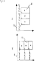
たとえば、両手をおろして立っている人物(第7(A)図)が両手を挙げることにより人物を囲む長方形の大きさが変化する(第7(B)図)。符号化効率を考えるとき、動きベクトルの符号量が少なくなるように、対象画像と参照画像とを同じ座標空間に変換する必要がある。
また、画像の大きさの変換により分割される画像のマクロブロックの配置が変化する。たとえば第7(A)図から第7(B)図に変化するときに、マクロブロック701はマクロブロック703と704の二つに分けられ圧縮符号化されるために、第7(B)図の再生画像において、人物の顔に量子化による垂直のひずみが出現し、視覚上の画質が低下する。
また、アフィン変換を高い精度で行うことが必要であるために、アフィンパラメータ(a,b,c,d,e,f等)は一般に小数点以下の実数であるため、高制度に伝送しようとすると、長いビット数で伝送する必要がある。
従来では、アフィンパラメータを単に量子化して固定長もしくは可変長符号で伝送するため、アフィンパラメータの精度を低下させ、高い精度のアフィン変換が得られず、所望の予測画像生成ができない。
(数1)から(数4)からわかるように、変換パラメータの個数は2個から10個、またはそれ以上のものがある。変換パラメータを伝送するには、その最大の個数にあわせて符号化すると少ないパラメータを伝送するときに冗長な符号を送ることになるという問題がある。
発明の開示
本発明の第1の目的は、アフィン変換のようにそのパラメータが整数でない多くの桁数を有する場合に、正確な変換をより少ないデータ伝送量で実現できるデジタル画像データ符号化、復号化装置を提供することである。
その目的を達成するために、入力画像を符号化してデータ圧縮する画像圧縮手段と、その画像圧縮手段により圧縮した画像を復号して得た画像を座標変換して、座標変換することにより発生する座標データを出力する座標変換手段と、この座標変換手段の座標データから変換パラメータを生成する変換パラメータ生成手段と、この変換パラメータ生成手段によって生成された変換パラメータを用いて、入力画像から予測画像を生成する予測画像生成手段と、前記圧縮画像と座標データを伝送する伝送手段と、を備え、画像予測符号化装置を構成したものである。
又、圧縮画像データと座標データを入力し、可変長復号する可変長復号手段と、前記可変長復号手段により復号された座標データから、変換パラメータを生成する変換パラメータ生成手段と、前記変換パラメータ生成手段により生成された変換パラメータを用いて予測画像データを生成する予測画像生成手段と、前記予測画像生成手段からの予測画像と前記可変長復号された圧縮画像データを加算することにより復号画像を生成する加算手段とを有するデジタル画像復号化装置である。
特に変換パラメータ生成手段が、N個(Nは自然数)の画素の座標点と、前記N個の座標点を所定の線形多項式によって変換されたN個の変換済み座標点とから変換パラメータを生成する符号化、復号化装置である。更に、変換パラメータ生成手段が、大きさの異なる第1から第Nの対象画像を入力し、前記第1から第Nの対象画像に対し、共通空間座標を設定し、前記第1から第Nの対象画像について、所定の方法で圧縮符号化し第1から第Nの圧縮画像を生成し、前記第1から第Nの圧縮画像を復号化し、前記共通空間座標に変換し、第1から第Nの伸張画像を生成して格納すると同時に、前記第1から第Nの伸張画像を前記共通空間座標に変換することによって生成される変換パラメータを出力するデジタル画像符号化、符号化装置である。
本発明の第二の目的は、特に座標データとして異なる大きさの画像を予測符号化するときに、対象画像と参照画像とを同じ座標空間に変換した座標データを伝送することにより動き検出の精度を向上させると同時に動きベクトルの符号量を少なくし画質の向上を図ったデジタル画像符号化、復号化装置である。
この目的を達成するために、本発明の画像予測符号化装置は、大きさの異なる第一から第Nの対象画像を入力し、第一から第Nの対象画像に対し、共通空間座標を設定し、第一の対象画像について、所定の方法で圧縮符号化し第一の圧縮画像を生成した後、第一の圧縮画像を復号化し、共通空間座標に変換し、第一の伸長画像を生成して格納すると同時に、第一の対象画像を共通空間座標に変換することによって生成される第一オフセット信号(座標データ)を符号化し、第一の圧縮画像と共に伝送し、第n(n=2,3,...N)の対象画像について、共通空間座標に変換し、第(n−1)の伸長画像を参照して予測画像を生成し、第nの対象画像と予測画像とから差分画像を生成して圧縮符号化し、第nの圧縮画像を生成した後、第nの圧縮画像を復号化し、共通空間座標に変換し、第nの伸長画像を生成して格納すると同時に、第nの対象画像を共通空間座標に変換することによって生成される第nのオフセット信号(座標データ)を符号化し、第nの圧縮画像と共に伝送するとしたものである。
また、本発明の画像予測復号化装置は、入力端子と、データ解析器と、復号化器と、加算器と、座標変換器と、動き補償器と、フレームメモリとを具備し、入力端子に、大きさの異なる第一から第Nの対象画像を符号化し、第n(n=2,3,...,N)の対象画像を共通空間座標に変換することによって生成される第nのオフセット信号を含めた第一から第Nの圧縮画像データを入力し、データ解析器にて、第一の圧縮画像データを分析し、第一の圧縮画像信号と第一のオフセット信号とを出力し、復号化器に第一の圧縮画像信号を入力し、第一の再生画像に復元した後、座標変換器にて、第一のオフセット信号を元もとに、第一の再生画像を座標変換し、フレームメモリに格納し、第n(n=2,3,...,N)の圧縮画像データについて、データ解析器にて、第nの圧縮画像データを分析し、第nの圧縮画像信号と第nのオフセット信号と第nの動き信号とを出力し、復号化器に第nの圧縮画像信号を入力し、第nの伸長差分画像に復元し、動き補償器に第nのオフセット信号と第nの動き信号とを入力し、第nのオフセット信号と第nの動き信号をもとに、フレームメモリに格納された第(n−1)の再生画像から第nの予測画像を取得し、加算器にて第nの伸長差分画像と第nの予測画像とを加算して第nの再生画像に復元し出力すると同時に、座標変換器にて、第nのオフセット信号をもとに、第nの再生画像を座標変換しフレームメモリに格納するとしたものである。
本発明の第三の目的は、座標データとして伝送するデータにアフィン変換を行う場合のアフィンパラメータを含む変換パラメータを高精度に伝送し、高精度な予測画像生成を可能にするデジタル画像符号化、復号化装置を提供することである。
この発明によると、可変長復号化部と、差分画像伸長部と、加算部と、変換パラメータ生成部と、予測画像生成部とフレームメモリとから構成するデジタル画像復号化装置で、可変長復号化部にデータを入力し、データから、差分画像データを分離し差分画像伸長部に伝送すると同時に、座標データを分離し変換パラメータ生成部に入力し、差分画像伸長部にて、差分画像データを伸長し、加算部に伝送し、変換パラメータ生成部にて、座標データから変換パラメータを生成し、予測画像生成部に伝送し、予測画像生成部にて、変換パラメータとフレームメモリから入力される画像とから予測画像生成し、加算部に伝送し、加算部にて、伸長された差分画像に予測画像を加算し、画像を生成し出力すると同時にフレームメモリに格納する。
上記の座標データは、N個の画素の座標点と、N個の座標点を所定の線形多項式によって変換されたN個の変換済み座標点であり、または、N個の画素の座標点と、N個の座標点を所定の線形多項式によって変換されたN個の変換済み座標点の差分値であり、または、所定のN個の座標点を所定の線形多項式によって変換されたN個の変換済み座標点であり、または、所定のN個の座標点を所定の線形多項式によって変換されたN個の変換済み座標点と予測値との差分値である。
この予測値は、所定のN個の座標点であり、または前フレームのN個の変換済み座標点である。
また、本発明によると、変換パラメータ推定部と、予測画像生成部と、第一加算部と、差分画像圧縮部と、差分画像伸長部と、第二加算部と、フレームメモリと、伝送部とから構成するデジタル画像符号化装置で、デジタル画像を入力し、変換パラメータ推定部にて、フレームメモリに格納されている画像とデジタル画像とから変換パラメータを推定し、予測画像生成部に、推定された変換パラメータとフレームメモリに格納された画像とを入力し、推定された変換パラメータに基づいて予測画像を生成し、第一加算部にて、デジタル画像と予測画像との差分を求め、差分画像圧縮部にて圧縮差分データに圧縮し、伝送部に送ると同時に、差分画像伸長部にて、圧縮差分データを伸長差分データに伸長し、第二加算部にて、予測画像と加算し、フレームメモリに格納するデジタル画像符号化装置において、変換パラメータ推定部から、座標データを伝送部に送り、圧縮差分データと共に伝送する。
上記の座標データは、N個の画素の座標点と、N個の座標点を変換パラメータによって変換されたN個の変換済み座標点であり、または、N個の画素の座標点と、N個の変換済み座標点とN個の画素の座標点との差分であり、または、所定のN個の画素の座標点を変換パラメータによって変換されたN個の変換済み座標点であり、N個の変換済み座標点と所定のN個の画素の座標点との差分であり、または、N個の変換済み座標点と過去のフレームのN個の変換済み座標点との差分である。
また、本発明によると、可変長復号化部と、差分画像伸長部と、加算部と、変換パラメータ生成部と、予測画像生成部とフレームメモリとから構成するデジタル画像復号化装置で、可変長復号化部にデータを入力し、データから、差分画像データを分離し差分画像伸長部に伝送すると同時に、座標データの個数の個数と座標データとを変換パラメータ生成部に入力し、差分画像伸長部にて、差分画像データを伸長し、加算部に伝送し、変換パラメータ生成部にて、変換パラメータの個数に基づいて変換パラメータ生成方法を切り替え、座標データから変換パラメータを生成し、予測画像生成部に伝送し、予測画像生成部にて、変換パラメータとフレームメモリから入力される画像とから予測画像生成し、加算部に伝送し、加算部にて、伸長された差分画像に前記予測画像を加算し、画像を生成し、出力すると同時にフレームメモリに格納する。
上記の座標データがN個の画素の座標点と、N個の座標点を所定の線形多項式によって変換されたN個の変換済み座標点であり、または、座標データがN個の画素の座標点と、N個の座標点を所定の線形多項式によって変換されたN個の変換済み座標点とN個の画素の座標点との差分であり、または、座標データがN個の画素の座標点と過去のフレームのN個の画像の座標点との差分と、N個の座標点を所定の線形多項式によって変換されたN個の変換済み座標点と過去のフレームのN個の変換済み座標点との差分であり、または、所定のN個の座標点を所定の線形多項式によって変換されたN個の変換済み座標点であり、または、所定のN個の座標点を所定の線形多項式によって変換されたN個の変換済み座標点と所定のN個の座標点との差分であり、または、所定のN個の座標点の線形多項式によって変換されたN個の変換済み座標点と過去のフレームのN個の変換済み座標点との差分である。
また、変換パラメータをそのまま伝送する際に、変換パラメータを画像サイズで定倍してから量子化し符号化し、または変換パラメータの最大値の指数部を求め、指数部で変換パラメータを正規化し、指数部と正規化された変換パラメータを伝送する。
【図面の簡単な説明】
第1図は本発明の実施例1による画像予測符号化装置を示すブロック図である。
第2図は本発明の実施例1、2における画像の座標変換を示す第一模式図である。
第3図は本発明の実施例1の画像予測符号化装置による符号化画像データ系列を示す模式図である。
第4図は本発明の実施例1、2における画像の座標変換を示す第二模式図である。
第5図は本発明の実施例2による画像予測復号化装置を示すブロック図である。
第6図は本発明の実施例1、2において分割された画像を示す模式図である。
第7図は従来の方法で分割された画像を示す模式図である。
第8図は本発明の実施例3のデジタル画像復号化装置のブロック図である。
第9図は本発明の実施例3のデジタル画像符号化装置のブロック図である。
第10図は本発明の実施例4のデジタル画像復号化装置のブロック図である。
第11図は本発明の実施例5のデジタル画像復号化装置のブロック図である。
第12図は本発明の実施例5のデジタル画像符号化装置のブロック図である。
発明を実施するための最良の形態
以下、本発明の実施例について、第1図から第12図を用いて説明する。
(実施例1)
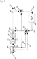
第1図は本発明の実施例1による画像予測符号化装置のブロック図を示し、第1図において101は入力端子、102は第一加算器、103は符号化器、106は出力端子、107は復号化器、110は第二加算器、111は第一座標変換器、112第二座標変換器、113は動き検出器、114は動き補償器、115はフレームメモリである。
以上のように構成された画像予測符号化装置について、以下、その動作を述べる。入力端子101に大きさの異なる第一から第Nの対象画像を入力する。Nは映像の長さによって決定される。
まず、入力端子101に第一の対象画像を入力し、第一加算器102を経由し、符号化器103にて圧縮符号化する。この場合、第一加算器102における引き算は行わない。また、本実施例では、対象画像を複数隣接するブロック(8x8画素)に分割し、離散コサイン変換器DCT(104)にて空間領域の信号を周波数領域の信号に変換して変換ブロックを生成する。
変換ブロックは量子化器Q(105)によって量子化され、第一の圧縮画像を生成し、出力端子106に出力し、固定長もしくは可変長の符号に変換して伝送する(図示されていない)。同時に、第一の圧縮画像を復号化器107にて伸長画像に復元する。本実施例では、逆量子化器IQ(108)によって逆量子化され、逆離散コサイン変換器(IDCT)109にて空間信号に変換される。
このように得られた再生画像を第一座標変換器111にて座標変換し、第一の再生画像をしてフレームメモリ115に格納する。
次に、第一座標変換器111の操作を説明する。第2(A)図を第一の対象画像とする。画像201の画素a1は、座標系203において(0,0)の座標をもつ。第2(C)図には新しい座標系205が設定されている。この座標系は表示画面の座標系でもいいし、または対象画像の中心点を原点とする座標系でもよい。
いずれの場合、座標系205は符号化をはじめる前にあらかじめ設定されるものである。対象画像201を座標系205にマッピングしたものは第2(C)図に示されている。
この座標変換により対象画像201の画素a1の座標が(x_a,y_a)になる。なお、回転を含めた座標変換を行うこともある。x_a,y_aの値を固定長、8bitに符号化して第一の圧縮画像と共に伝送する。
次に、第n(n=2,3,...,N)の対象画像を入力端子101に入力する。第nの対象画像をライン126を経由し第二の座標変換器112に入力し、座標系205に変換する。第2(B)図の画像202を第nの対象画像とする。
それを座標系205にマッピングし、画素b1の座標を(x_b,y_b)に変換する(第2(C)図)。座標変換された対象画像202を動き検出器113に入力し、複数のブロックに分割してフレームメモリ115に格納された第(n−1)の再生画像を参照し、ブロックマッチングなどの方法で動き検出し、動きベクトルを生成する。
生成された動きベクトルをライン128に出力し符号化し伝送する(図示されていない)と同時に動き補償器114に送られ、フレームメモリ115に格納された第(n−1)の再生画像をアクセスし予測ブロックを生成する。動き検出・動き補償についての実施例は、たとえばUSP5,193,004に開示されている。
第一加算器102に、第nの対象画像のブロックとその予測ブロックを入力して差分ブロックを生成する。差分ブロックを符号化器103にて圧縮し、第nの圧縮画像を生成し出力端子106に出力すると同時に、復号化器107にて伸長差分ブロックに復元する。
第二の加算器110にて、伸長差分ブロックにライン125を経由して送られる予測ブロックを加算し、画像を再生する。このように再生された画像を第一の座標変換器111に入力し、第2(C)図の画像202と同じように座標変換し、第nの再生画像としてフレームメモリ115に格納すると同時に、画素b1の座標(x_b,y_b)を符号化し第nの圧縮画像と共に伝送する。
第3図は本発明の実施例の画像予測符号化装置による符号化画像データ系列を示す模式図である。符号化画像データの先頭に画像同期信号303、続いて、座標変換によるパラメータx_a(304),y_a(305)、画像のサイズ306、307、量子化に用いられるステップ値308がある。
そのあと、動きベクトルや画像の圧縮データが続く。即ち座標データとしてパラメータx_a(304),y_a(305)、画像のサイズ306、307が伝送されることになる。
第4図は本発明の実施例における画像の座標変換の別の形態を示す。この場合、対象画像を複数の領域に分割され、それぞれの領域について座標変換を行う。
たとえば、画像201を三つの領域R1,R2,R3に分割し、それぞれの領域を圧縮・伸長してから、第一の座標変換器111にて再生されたR1、R2、R3の領域をそれぞれ座標変換し、フレームメモリ115に格納する。座標変換に用いられるパラメータ(x_a1,y_a1),(x_a2,y_a2),(x_a3,y_a3)を同時符号化して伝送する。
次に、画像202を入力し、領域R4,R5,R6に分割され、それぞれの領域を第二の座標変換器112にて座標変換する。各座標変換された領域について、フレームメモリ115に格納された領域を参照し動き検出・動く補償を行い、予測信号を生成し、第一の加算器102にて差分信号を生成し、圧縮・伸長してから、第二の加算器にて予測信号を加算する。
このように再生された各領域をそれぞれ座標変換してフレームメモリ115に格納する。座標変換に用いられるパラメータ(x_b1,y_b1),(x_b2,y_b2),(x_b3,y_b3)を同時符号化して伝送する。
異なる大きさの画像を共通の空間座標に変換することにより、動き検出の精度を向上させると同時に動きベクトルの符号量を少なくし画質を向上させることができる。
第6(A)図と第6(B)図の画像を点605に座標をあわせることにより、ブロック601とブロック603、ブロック602とブロック604が一致しているので、動き検出は正確に求められる。
またこの例では、ブロック603とブロック604の動きベクトルがゼロに近い値になるため動きベクトルの符号量を削減することができる。一般の画像について、隣接する二つの画像についても同じことがいえる。また、第7(B)図と違って、第6(B)図のブロック603の顔は一つのブロックに収まるために、顔に量子化による垂直のひずみは出現しない。
(実施例2)
第5図は本発明の実施例2による画像予測復号化装置にブロック図を示し、第5図において501は入力端子、502はデータ解析器、503は復号化器、506は加算器、507は出力端子、508は座標変換器、509は動き検出器、510はフレームメモリである。
以上のように構成された画像予測符号化装置について、以下、その動作を述べる。入力端子501に、大きさの異なる第一から第Nの対象画像を符号化し、第n(n=1,2,3,...,N)の対象画像を共通空間座標に変換することによって生成される第nの変換パラメータを含めた第一から第Nの圧縮画像データを入力する。第3図の模式図は圧縮画像データの一例を示す。データ解析器502にて入力された圧縮画像データを解析する。
まず第一の圧縮画像データをデータ解析器502にて解析し、第一の圧縮画像を復号化器503に出力する。また、共通空間座標に変換することによって生成される第一の変換パラメータ(第2(C)図のx_a,y_a)をライン520を経由して座標変換器508に送る。
復号化器503では、第一の圧縮画像を伸長画像に復元し、出力端子507に出力する。同時に伸長画像を座標変換器508に入力する。本実施例では、逆量子化し、IDCTを施して空間領域の信号に復元する。
座標変換器508では第一の変換パラメータをもとに、伸長画像を共通空間座標系にマッピングし、第一の再生画像として出力し、フレームメモリ510に格納する。座標変換について実施例1にて説明したのと同じである。
次に第n(n=2,3,...,N)の圧縮画像データをデータ解析器502にて解析し、第nの圧縮差分画像を復号化器503に出力する。また、第nの動きデータをライン521を経由し動き補償器509に送り、共通空間座標に変換することによって生成される第nの変換パラメータ(第2(C)図のx_b,y_bに相当)をライン520を経由して座標変換器508および動き補償器509に送る。
復号化器503では、第nの圧縮差分画像を第nの伸長差分画像に復元し、加算器506に出力する。本実施例では、対象ブロックの差分信号を逆量子化し、IDCTし、伸長差分ブロックとして出力する。
一方、動き補償器509では、第n変換パラメータと該当ブロックの動きベクトルを用いて、フレームメモリ510から予測ブロックを取得する。
本実施例では、対象ブロックの座標を変換パラメータを用いて変換し、すなわち対象ブロックの座標に第nの変換パラメー第2(C)図のx_b,y_b)を加算し、その和に動きベクトルを加算することにより、フレームメモリ510の番地を決定する。このようにして得られた予測ブロックを加算器506に送り、伸長差分ブロックと加算し、画像を再生する。再生された画像を出力端子507に出力すると同時に、座標変換器508にて第nの変換パラメータを用いて座標変換してフレームメモリ510に格納する。
なお、座標変換器508の代わりに、動き補償器509またはその前後に於いて、対象ブロックの座標に第n番目の画像と第n−1番目の画像の変換パラメータの差分(x_b−x_a,y_b−y_a)を加算し、それに動きベクトルを加算する機能を有する他の装置を付加して、フレームメモリ510の番地を決定しても同様な効果を有することは言うまでもない。
次に入力端子501に別の圧縮画像データを入力する場合を考える。すなわち、大きさの異なる第一から第Nの対象画像を複数の対象領域に分割し符号化して、それぞれの対象領域を共通空間座標に変換することによって生成される変換バラメータを含めた第一から第Nの圧縮画像データを入力する。
まず記第一の圧縮画像データをデータ解析器502にて分析し、第m(m=1,2,...,M)の圧縮領域を復号化器503に出力する。第4(A)図ではM=3。また、共通空間座標に変換することによって生成される第mの変換パラメータ(第4(A)図のx_am,y_am,m=1,2,3)をライン520を経由して座標変換器508に送る。復号化器503では、第mの圧縮領域を第mの伸長領域に復元し、出力端子507に出力する。同時に第mの伸長領域を座標変換器508に入力する。
そこで第mの変換パラメータをもとに、第mの伸長領域を共通空間座標系にマッピングし、第mの再生領域として出力し、フレームメモリ510に格納する。方法は前述と同じである。
次に第n(n=2,3,...,N)の圧縮画像データをデータ解析器502にて解析し、その中にある第k(k=1,2,...,K)の圧縮差分領域を復号化器503に出力する。第4(B)図ではK=3。
また、対応する動きデータをライン521を経由し動き検出器509に送り、共通空間座標に変換することによって生成される第kの変換パラメータ(第4(B)図のx_bk,y_bk,k=1,2,3)をライン520を経由して座標変換器508および動き補償器509に送る。
復号化器503では、第kの圧縮差分領域を第kの伸長差分領域に復元し、加算器506に出力する。本実施例では、対象ブロックの差分信号を逆量子化し、IDCTし、伸長差分ブロックとして出力する。
一方、動き補償器509では、第kの変換パラメータと該当ブロックの動きベクトルを用いて、フレームメモリ510から予測ブロックを取得する。本実施例では、対象ブロックの座標を第kの変換パラメータの用いて変換し、すなわち対象ブロックの座標に第k変換パラメータ(たとえば第4(B)図のx_bk,y_bk,k=1,2,3)を加算し、その和に動きベクトルを加算することにより、フレームメモリ510の番地を決定する。
このようにして得られた予測ブロックを加算器506に送り、伸長差分ブロックと加算し、画像を再生する。再生された画像を出力端子507に出力すると同時に、座標変換器508にて座標変換してフレームメモリ510に格納する。
(実施例3)
第8図は本発明による実施例3の復号化装置のブロック図を示す。入力端子801、可変長復号化部802、差分画像伸長部803、加算部804、出力端子805、変換パラメータ生成部806、フレームメモリ807と予測画像生成部808から構成される。
圧縮符号化された画像データを入力端子801に入力する。可変長復号化802では、入力データを解析し、差分画像データや座標データを分離し、それぞれ、ライン8002と8003を経由して差分画像伸長部803と変換パラメータ生成部806に送る。
差分画像データには、DCTされ、量子化された変換係数と量子化幅が含まれる。差分画像伸長部803では、変換係数を量子化幅を利用して逆量子した後に逆DCTをし、差分画像に伸長する。
一方、座標データには、変換パラメータを生成するためのデータが含まれ、変換パラメータ生成部806にて、変換パラメータを生成する。たとえば、(数3)に示すアフィン変換の場合、(a,b,c,d,e,f)が生成される。詳細について以下に説明する。
変換パラメータ生成部806にて生成された変換パラメータと、フレームメモリに格納される画像を予測画像生成部808に入力する。(数3)に示すアフィン変換の場合、変換パラメータ生成部806から送られる(a,b,c,d,e,f)を用いて、(数3)にしたがって、(x,y)にある画素の予測値はフレームメモリに格納される画像の(u,v)にある画素になる。(数1)、(数2)、(数4)の場合についても同じである。
このようにして生成された予測画像を加算部804に送り、差分画像に加算し、画像を再生する。再生された画像は出力端子805に出力すると同時にフレームメモリ807に格納する。
さて、上述の座標データは複数の形態をとることが可能で、以下に説明する。
座標データがN個の画素の座標点と、そのN個の座標点を所定の線形多項式によって変換されたN個の変換済み座標点とからなる場合を考える。
ここに、Nは変換パラメータを求めるために必要な点の個数である。アフィンパラメータの場合、6つのパラメータがあるので、6つの変数を解くには6つの式を必要とする。一つの座標点には(x,y)の成分があるために、N=3であれば、6つのアフィン変数パラメータを解くことができる。
(数1)の場合、N=1、(数2)の場合N=2、(数4)の場合N=5である。N個の変換済み座標点は動きベクトルであり、(数1)から(数4)の左辺の(u,v)に相当する。
アフィン変換の場合、3個の座標点(x0,y0),(x1,y1),(x2,y2)と変換済み座標点(u0,v0),(u1,v1),(u2,v2)ラインが8003を経由し変換パラメータ生成部806に入力する。変換パラメータ生成部806では、下記に連立方程式を解くことにより、アフィンパラメータが得られる。
[数5]
(u0,v0)=(ax0+by0+e,cx0+dy0+f)
(u1,v1)=(ax1+by1+e,cx1+dy1+f)
(u2,v2)=(ax2+by2+e,cx2+dy2+f)
なお、より多くの座標データを用いて変換パラメータを求めることも可能である。ほかの場合も同様に変換パラメータを解くことができる。N個の(x,y)をうまく選択することにより非常に高精度な変換パラメータを求めることができる。直角に配置されるN個の(x,y)が好ましい。
なお、変換済みの座標点(u0,v0),(u1,v1),(u2,v2)に対し、対応する座標点(x0,y0),(x1,y1),(x2,y2)を求めるときには、(数5)の代わりに(数6)の連立方程式を求めてもよい。
[数6]
(x0,y0)=(Au0+Bv0+E,Cu0+Dv0+F)
(x1,y1)=(Au1+Bv1+E,Cu1+Dv1+F)
(x2,y2)=(Au2+Bv2+E,Cu2+Dv2+F)
次に、座標データが、N個の画素の座標点と、N個の座標点を所定の線形多項式によって変換されたN個の変換済み座標点の差分値である場合を考える。差分をとるための予測値がN個の画素の座標点の場合、変換パラメータ生成部806にて、N個の画素の座標点とN個の変換済み座標点の差分値とを加算し、N個の画素の座標点と加算したN個の変換済み座標点とから変換パラメータを生成する。
なお、差分をとるための予測値が前のフレームのN個の画素の変換済み座標点の場合、変換パラメータ生成部806にて、前のフレームのN個の変換済み座標点とN個の変換済み座標点の差分値とを加算し、N個の画素の座標点と加算したN個の変換済み座標点とから変換パラメータを生成する。加算したN個の変換済み座標点を次のフレームの予測値として、格納しておく。
次に、座標データが、所定のN個の座標点を所定の線形多項式によって変換されたN個の変換済み座標点である場合を考える。所定のN個の座標点はあらかじめに定められた座標点であり、伝送する必要がない。変換パラメータ生成部806にて、所定のN個の画素の座標点とN個の変換済み座標点とから変換パラメータを生成する。
次に、座標点が、所定のN個の座標点を所定の線形多項式によって変換されたN個の変換済み座標点の差分値である場合を考える。差分をとるための予測値がN個の画素の座標点の場合、変換パラメータ生成部806にて、N個の画素の座標点とN個の変換済み座標点の差分値とを加算し、N個の画素の座標点と加算したN個の変換済み座標点とから変換パラメータを生成する。
なお、差分をとるための予測値が前のフレームのN個の画素の変換済み座標点の場合、変換パラメータ生成部806にて、前のフレームのN個の変換済み座標点とN個の変換済み座標点の差分値とを加算し、N個の画素の座標点と加算したN個の変換済み座標点とから変換パラメータを生成する。加算したN個の変換済み座標点を次のフレームの予測値として、格納しておく。
第9図は本発明の実施例3の符号化装置のブロック図である。入力端子901と、変換パラメータ推定部903と、予測画像生成部908と、第一加算部904と、差分画像圧縮部905と、差分画像伸長部910と、第二加算部911と、フレームメモリ909と、伝送部906とから構成される。入力端子901にデジタル画像を入力する。変換パラメータ推定部903にて、フレームメモリに格納されている画像とデジタル画像とから変換パラメータを推定する。アフィンパラメータの推定方法について前述した通りである。
なお、フレームメモリに格納されている画像のかわりに、その原画像を用いてもよい。変換パラメータ推定部903で推定された変換パラメータはライン9002を経由して予測画像生成部908に送る。
また、変換パラメータを用いて変換された座標データをライン9009を経由し伝送部906に送る。座標データについて複数の形態をもつことが可能で、前述した通りである。
予測画像生成部908では、推定された変換パラメータとフレームメモリ909に格納された画像とを入力し、推定された変換パラメータに基づいて前述したように予測画像を生成する。次に、第一加算部904にて、デジタル画像と予測画像との差分を求め、差分画像圧縮部905にて圧縮差分データに圧縮し、伝送部906に送る。
差分画像圧縮905では、差分画像をDCTし量子化する。同時に、差分画像伸長部910にて、圧縮差分データを伸長差分データに伸長する。差分画像伸長部910では、逆量子化と逆DCTが施される。伸長差分データを第二加算部にて、予測画像と加算しフレームメモリに格納する。伝送部906では、圧縮差分データ、量子化幅、座標データを符号化し、多重化した後に伝送・蓄積する。
(実施例4)
第10図は本発明による実施例4のデジタル画像復号化装置である。入力端子1001と、可変長復号化部1002と、差分画像伸長部1003と、加算部1004と、変換パラメータ生成部1006と、予測画像生成部1008とフレームメモリ1007とから構成する。基本的な動作は第8図と同じである。異なるところについてのみ説明する。
変換パラメータ生成部1006は複数の種類の変換パラメータが生成できる構成になっている。パラメータ生成部1006aは(数2)に示すパラメータ(a,e,d,f)、パラメータ生成部1006bは(数3)に示すパラメータ(a,b,e,c,d,f)、パラメータ生成部1006cは(数4)に示すパラメータ(g,p,r,a,b,e,h,q,s,c,d,f)を生成する手段から構成される。
(数2)は2つの座標点、(数3)は6つの座標点、(数4)は12個の座標点があればパラメータが生成できる。この座標点の個数はライン10010を経由し、スイッチ1009と1010とを制御する。座標点の個数が2のときスイッチ1009と1010とをそれぞれ端子1011aと1012aに接続し、座標データをライン10003を経由しパラメータ生成部1006aに送り、連立方程式を解くことにより(数2)のパラメータを生成し端子1012aから出力する。
座標点の個数が3、6のときはそれぞれパラメータ生成部1006bと1006cに接続する。このようにして、座標点の個数情報より、伝送する座標データの種類がわかり、切り替えて変換パラメータを生成することが可能である。
ライン10003を経由する座標データの形態は前述した通りである。なお、(数2)から(数4)の右辺の(x,y)が既知の場合、伝送する必要がないため、ライン10010を経由する座標点の個数は、(数2)に対し1、(数3)に対し3、(数4)に対し6と対応させても可能である。さらに、変換パラメータ生成部は3つに限るものではなく、それ以上があってもよい。
(実施例5)
第11図と第12図は本発明による実施例5のデジタル画像復号化装置と符号化装置のブロック図を示す。基本的には第8図と第9図と同じである。異なるところは、変換パラメータ生成部806のかわりに、変換パラメータ伸長部1106となり、また、変換パラメータ推定部903と1203の動作が多少異なる。これについて説明する。
第12図の変換パラメータ推定部1203では変換パラメータを推定した後に、それを画像サイズで定倍し、量子化してからライン12009経由して伝送部1206に送る。変換パラメータは実数値であり、定倍してからさらに整数化する必要がある。
アフィンパラメータの場合、(a,b,c,d)は高精度に表現する必要がある。aとcは垂直座標のパラメータで、画像の垂直の画素数Vを乗算し、またbとdは水平座標のパラメータで、画像の水平の画素数Hで乗算する。
また、(数4)のように二乗の項がある場合、定培する画像サイズを同じ二乗(H2,V2,HV)にしても可能である。第11図の変換パラメータ伸長部1106では、定培されたパラメータを除算し、パラメータを再生する。
また、第12図の変換パラメータ推定部1203では変換パラメータを推定した後に、変換パラメータの最大値を求める。好ましくは、絶対値の最大値がよい。その最大値の指数部(好ましくは2のべき乗の指数部)で、変換パラメータを正規化する。すなわち各変換パラメータに指数部の値を乗算する。
このように正規化された変換パラメータと指数部を伝送部1206に送り、固定長符号に変換して伝送する。第11図の変換パラメータ伸長部1106では、正規化された変換パラメータを指数部で除算し変換パラメータに伸長する。
アフィンパラメータ(a,b,c,d)の場合、(a,b,c,d)の中から最大値を求める。平行移動のパラメータ(e,f)を含めてもよいが、普通値の大きさが桁数が違うので、含めない。数4のパラメータについても同様で、二乗の項と一乗の項のパラメータをわけて正規化することは好ましいが、これに限ることではない。
上述したすべての実施例では、差分画像が非ゼロな場合について説明したが、差分画像が完全にゼロの場合も同じである。この場合、予測画像がそのまま出力されることになる。また、画像全体の変換について説明したが、二次元もしくは三次元の画像を複数の小領域に分割し、各小領域にアフィン変換をはじめとした変換を施す場合も同じように適用可能である。
産業上の利用可能性
以上のように本発明によれば、大きさの異なる画像を同じ座標系に変換してから動き検出し予測画像を生成することにより動き検出の精度を向上すると同時に動きベクトルの符号量を削減する効果が得られる。
また、復号化側で座標データから変換パラメータを求めることにより、精度の高い変換パラメータが得られ、高精度な予測画像生成が可能になる。また、変換パラメータを正規化したり、画像サイズで定倍することにより、画像に応じた精度でパラメータを伝送することができる。
さらに、座標データの個数によって変換パラメータの生成を切り替えることにより、変換パラメータの生成が最適な処理が可能になると同時に、座標データを効率よく伝送できる。Technical field
The present invention relates to an encoding / decoding method and apparatus for storing or transmitting digital image data, and more particularly to a method and apparatus for encoding / decoding motion information in image prediction and generating a predicted image with high accuracy. It is about.
Background art
In order to efficiently store or transmit a digital image, it is necessary to perform compression encoding. As a method for compressing and encoding a digital image, there is a waveform encoding method such as a subband, a wearlet, and a fractal, in addition to a discrete cosine transform (DCT) represented by a conventional JPEG or MPEG.
To remove redundant signals between images, image prediction using motion compensation is performed, and the difference signal is waveform-encoded.
Here, the MPEG system based on the motion compensation DCT will be described. The input image is divided into a plurality of 16 × 16 macroblocks and processed. One macroblock is further divided into 8x8 blocks, subjected to 8x8 DCT, and then quantized. This is called intra-frame coding.
On the other hand, with a motion detection method such as block matching, a predicted macroblock having the smallest error in the target macroblock is detected from another frame adjacent to the time, and based on the detected motion, Perform motion compensation and obtain an optimal prediction block. A signal indicating a predicted macroblock having the smallest error is a motion vector.
Next, the difference between the target block and the corresponding prediction block is obtained, DCT is performed, the transform coefficient is quantized, and transmitted or stored together with the motion information. This is called inter-frame coding.
On the receiving side, after restoring the quantized transform coefficients to the original difference signal, a prediction block is obtained based on the motion vector, added to the difference signal, and an image is reproduced.
Although the generation of the predicted image is performed in block units, the entire image sometimes moves like panning or zooming. In this case, the entire image is motion-compensated. The motion compensation or the generation of the predicted image may be accompanied by deformation such as enlargement / reduction / rotation from simple parallel movement.
(Equation 1) to (Equation 4) show equations representing movement and deformation. (X, y) is the coordinates of the pixel, (u, v) is the transformed coordinates, and is the motion vector at (x, y). Other variables are conversion parameters indicating movement and deformation.
[Equation 1]
(U, v) = (x + e, y + f)
[Equation 2]
(U, v) = (ax + e, dy + f)
[Equation 3]
(U, v) = (ax + by + e, cx + dy + f)
[Equation 4]
(U, v) = (gx2 + pxy + ry2 + ax + by + e, h
x2 + qxy + sy2cx + dy + f)
The transformation of (Equation 3) is called an affine transformation, which will be described below as an example. The parameters (a, b, c, d, e, f) of the affine transformation can be obtained as follows.
First, an image is divided into a plurality of blocks (2x2, 4x4, 8x8, etc.), and a motion vector of each block is obtained by a block matching method. An affine parameter is obtained by selecting at least three highly reliable motion vectors from the obtained motion vectors and solving six simultaneous equations of Formula 3. Generally, in order to reduce the error, more points are selected and the affine parameters are obtained by the least squares method.
The affine parameters determined in this way are used for predictive image generation. It is necessary to transmit the affine parameters to the receiving side so that the same predicted image can be generated.
However, the conventional interframe coding presupposes that the target image and the reference image have the same size, and does not sufficiently deal with images of different sizes. The change in the size of two adjacent images is often due to the movement of an object in the images.
For example, a person standing with both hands down (FIG. 7 (A)) raises both hands to change the size of the rectangle surrounding the person (FIG. 7 (B)). When considering the coding efficiency, it is necessary to convert the target image and the reference image into the same coordinate space so that the amount of code of the motion vector is reduced.
Further, the arrangement of the macroblocks of the image to be divided by the conversion of the image size changes. For example, when changing from FIG. 7 (A) to FIG. 7 (B), the
In addition, since it is necessary to perform affine transformation with high accuracy, affine parameters (a, b, c, d, e, f, etc.) are generally real numbers below the decimal point. Need to be transmitted with a long number of bits.
In the related art, since the affine parameters are simply quantized and transmitted using a fixed length or variable length code, the accuracy of the affine parameters is reduced, high-precision affine transformation cannot be obtained, and a desired predicted image cannot be generated.
As can be seen from (Equation 1) to (Equation 4), the number of conversion parameters ranges from 2 to 10 or more. When transmitting the conversion parameters, if the coding is performed in accordance with the maximum number, there is a problem that a redundant code is transmitted when transmitting a small number of parameters.
Disclosure of the invention
A first object of the present invention is to provide a digital image data encoding / decoding apparatus capable of realizing accurate conversion with a smaller data transmission amount when its parameter has a large number of non-integer digits such as affine transformation. To provide.
In order to achieve the object, an image compression unit that encodes an input image and compresses the data, and an image obtained by decoding an image compressed by the image compression unit are subjected to coordinate transformation and coordinate transformation are performed. A coordinate conversion unit that outputs coordinate data, a conversion parameter generation unit that generates a conversion parameter from the coordinate data of the coordinate conversion unit, and a prediction image from the input image using the conversion parameter generated by the conversion parameter generation unit. The image predictive encoding apparatus comprises a predicted image generating means for generating, and a transmitting means for transmitting the compressed image and the coordinate data.
A variable length decoding unit that inputs the compressed image data and the coordinate data and performs variable length decoding; a conversion parameter generation unit that generates a conversion parameter from the coordinate data decoded by the variable length decoding unit; Means for generating predicted image data using the conversion parameters generated by the means, and generating a decoded image by adding the predicted image from the predicted image generating means and the compressed image data subjected to the variable length decoding. And a digital image decoding device having an adding means for performing the above operation.
In particular, the conversion parameter generation means generates a conversion parameter from N (N is a natural number) pixel coordinate points and N converted coordinate points obtained by converting the N coordinate points by a predetermined linear polynomial. It is an encoding and decoding device. Further, the conversion parameter generating means inputs the first to Nth target images having different sizes, sets common space coordinates for the first to Nth target images, and sets the first to Nth target images. The target image is compression-encoded by a predetermined method to generate first to N-th compressed images, decode the first to N-th compressed images, convert them to the common space coordinates, and convert the first to N-th compressed images. A digital image encoding and encoding apparatus that generates and stores an expanded image and outputs a conversion parameter generated by converting the first to Nth expanded images into the common space coordinates.
A second object of the present invention is to improve the accuracy of motion detection by transmitting coordinate data obtained by transforming a target image and a reference image into the same coordinate space, particularly when predictively encoding images of different sizes as coordinate data. And a digital image encoding / decoding device which improves the image quality by simultaneously reducing the amount of motion vector codes.
In order to achieve this object, the image prediction encoding apparatus of the present invention inputs first to Nth target images having different sizes and sets common space coordinates for the first to Nth target images. Then, for the first target image, after compression encoding by a predetermined method to generate a first compressed image, the first compressed image is decoded, converted to common space coordinates, and a first expanded image is generated. At the same time, the first offset signal (coordinate data) generated by converting the first target image into the common space coordinates is encoded and transmitted together with the first compressed image, and the n-th (n = 2, (3)... N) target image is transformed into common space coordinates, a predicted image is generated by referring to the (n−1) th expanded image, and a difference image is generated from the nth target image and the predicted image. Is generated and compression-encoded to generate an n-th compressed image, and then the n-th compressed image At the same time, the n-th offset signal (coordinate data) generated by converting the n-th target image into the common space coordinates is converted into the n-th decompressed image by decoding and converting it into the common space coordinates. It is encoded and transmitted together with the n-th compressed image.
Further, the image prediction decoding apparatus of the present invention includes an input terminal, a data analyzer, a decoder, an adder, a coordinate converter, a motion compensator, and a frame memory. , N-th target images generated by encoding the first through N-th target images having different sizes and converting the n-th (n = 2, 3,..., N) target images into common space coordinates. The first to Nth compressed image data including the offset signal is input, the first compressed image data is analyzed by the data analyzer, and the first compressed image signal and the first offset signal are output. After the first compressed image signal is input to the decoder and restored to the first reproduced image, the coordinate converter converts the first reproduced image based on the first offset signal. Then, the data is stored in the frame memory, and the n-th (n = 2, 3,..., N) compressed image data is Analyzing the n-th compressed image data, outputting the n-th compressed image signal, the n-th offset signal, and the n-th motion signal, inputting the n-th compressed image signal to the decoder, The n-th offset signal and the n-th motion signal are input to the motion compensator, and the n-th offset signal and the n-th motion signal are stored in the frame memory based on the n-th offset signal and the n-th motion signal. The n-th predicted image is acquired from the (n-1) reproduced image, and the adder adds the n-th decompressed difference image and the n-th predicted image to restore and output the n-th reproduced image. , The coordinate converter converts the coordinates of the n-th reproduced image based on the n-th offset signal, and stores the coordinates in the frame memory.
A third object of the present invention is to transmit a conversion parameter including an affine parameter when performing affine transformation to data transmitted as coordinate data with high accuracy, and to perform digital image encoding that enables highly accurate prediction image generation. It is to provide a decoding device.
According to the present invention, a digital image decoding device including a variable length decoding unit, a difference image decompression unit, an addition unit, a conversion parameter generation unit, a prediction image generation unit, and a frame memory performs variable length decoding. Input the data to the unit, separate the difference image data from the data, and transmit it to the difference image decompression unit.At the same time, separate the coordinate data and input it to the conversion parameter generation unit. The difference image decompression unit decompresses the difference image data. The conversion parameter generation unit generates a conversion parameter from the coordinate data, transmits the conversion parameter to the prediction image generation unit, and transmits the conversion parameter and the image input from the frame memory to the prediction image generation unit. , A predicted image is generated, and transmitted to the adding unit. The adding unit adds the predicted image to the decompressed difference image, generates and outputs the image, and simultaneously stores the image in the frame memory.
The coordinate data is a coordinate point of N pixels and N converted coordinate points obtained by converting the N coordinate points by a predetermined linear polynomial, or a coordinate point of N pixels, It is a difference value of N converted coordinate points obtained by converting N coordinate points by a predetermined linear polynomial, or N converted points obtained by converting predetermined N coordinate points by a predetermined linear polynomial It is a coordinate point or a difference value between the N converted coordinate points obtained by converting a predetermined N coordinate points by a predetermined linear polynomial and a predicted value.
This predicted value is a predetermined number of N coordinate points or N converted coordinate points of the previous frame.
According to the present invention, a conversion parameter estimating unit, a predicted image generating unit, a first adding unit, a differential image compressing unit, a differential image decompressing unit, a second adding unit, a frame memory, a transmitting unit, In the digital image encoding device configured from the above, a digital image is input, a conversion parameter estimation unit estimates a conversion parameter from the image stored in the frame memory and the digital image, and a prediction image generation unit estimates the conversion parameter. Input the converted parameters and the image stored in the frame memory, generate a predicted image based on the estimated conversion parameters, determine the difference between the digital image and the predicted image in the first addition unit, The compression unit compresses the compressed difference data and sends it to the transmission unit.At the same time, the difference image decompression unit decompresses the compressed difference data to decompressed difference data, and adds it to the predicted image in the second addition unit. In the digital image encoding device to be stored in the frame memory, the transformation parameter estimator, sends the coordinate data to the transmission unit, transmits with compressed difference data.
The coordinate data is a coordinate point of N pixels and N converted coordinate points obtained by converting the N coordinate points by the conversion parameter, or a coordinate point of N pixels and N coordinate points. Or the difference between the coordinate points of the N pixels and the coordinate points of the N pixels, or N converted coordinate points obtained by converting the coordinate points of predetermined N pixels using the conversion parameter, and This is the difference between the transformed coordinate points and the coordinate points of predetermined N pixels, or the difference between the N transformed coordinate points and the N transformed coordinate points of the past frame.
Further, according to the present invention, a digital image decoding apparatus including a variable length decoding unit, a difference image decompression unit, an addition unit, a conversion parameter generation unit, a prediction image generation unit, and a frame memory, has a variable length decoding unit. Data is input to the decoding unit, and the differential image data is separated from the data and transmitted to the differential image decompression unit. At the same time, the number of coordinate data and the coordinate data are input to the conversion parameter generation unit, and the differential image decompression unit is input. In, the difference image data is decompressed and transmitted to the adding unit. The conversion parameter generation unit switches the conversion parameter generation method based on the number of conversion parameters, generates a conversion parameter from the coordinate data, and generates a prediction image generation unit. The prediction image generation unit generates a prediction image from the conversion parameters and the image input from the frame memory, transmits the prediction image to the addition unit, and decompresses the image by the addition unit. By adding the predicted image to the difference image to generate an image, stored in the frame memory and simultaneously output.
The coordinate data is coordinate points of N pixels and N converted coordinate points obtained by converting the N coordinate points by a predetermined linear polynomial, or the coordinate data is coordinate points of N pixels. And the difference between the N converted coordinate points obtained by converting the N coordinate points by a predetermined linear polynomial and the coordinate points of the N pixels, or the coordinate data is the difference between the coordinate points of the N pixels. The difference between the coordinate points of the N images in the past frame, the N transformed coordinate points obtained by transforming the N coordinate points by a predetermined linear polynomial, and the N transformed coordinate points of the past frame , Or N converted coordinate points obtained by converting predetermined N coordinate points by a predetermined linear polynomial, or by converting predetermined N coordinate points by a predetermined linear polynomial. Between the converted N coordinate points and the predetermined N coordinate points A minute or a difference between the N transformed coordinates points of predetermined N pieces of N transformed by a linear polynomial of the coordinate points of the transformed coordinate point and the past frame.
Also, when transmitting the conversion parameter as it is, the conversion parameter is multiplied by the image size and then quantized and coded, or the exponent part of the maximum value of the conversion parameter is obtained, the conversion parameter is normalized by the exponent part, and the exponent part is obtained. And the normalized conversion parameters.
[Brief description of the drawings]
FIG. 1 is a block diagram showing an image prediction encoding apparatus according to
FIG. 2 is a first schematic diagram showing coordinate conversion of an image in the first and second embodiments of the present invention.
FIG. 3 is a schematic diagram showing an encoded image data sequence by the image predictive encoding device according to the first embodiment of the present invention.
FIG. 4 is a second schematic diagram showing coordinate conversion of an image in the first and second embodiments of the present invention.
FIG. 5 is a block diagram showing an image prediction decoding apparatus according to
FIG. 6 is a schematic view showing an image divided in
FIG. 7 is a schematic diagram showing an image divided by a conventional method.
FIG. 8 is a block diagram of a digital image decoding apparatus according to
FIG. 9 is a block diagram of a digital image encoding device according to
FIG. 10 is a block diagram of a digital image decoding apparatus according to
FIG. 11 is a block diagram of a digital image decoding apparatus according to
FIG. 12 is a block diagram of a digital image encoding apparatus according to
BEST MODE FOR CARRYING OUT THE INVENTION
Hereinafter, embodiments of the present invention will be described with reference to FIGS. 1 to 12.
(Example 1)
FIG. 1 is a block diagram of an image predictive encoding apparatus according to
The operation of the image predictive encoding device configured as described above will be described below. First to N-th target images having different sizes are input to an
First, a first target image is input to an
The transform block is quantized by a quantizer Q (105), generates a first compressed image, outputs the first compressed image to an
The thus obtained reproduced image is subjected to coordinate conversion by the first coordinate
Next, the operation of the first coordinate
In any case, the coordinate
By this coordinate conversion, the coordinates of the pixel a1 of the
Next, the n-th (n = 2, 3,..., N) target image is input to the
It is mapped to the coordinate
The generated motion vector is output to a
The block of the n-th target image and its prediction block are input to the
The
FIG. 3 is a schematic diagram showing an encoded image data sequence by the image predictive encoding device according to the embodiment of the present invention. At the head of the encoded image data, there is an
This is followed by motion vectors and compressed image data. That is, parameters x_a (304) and y_a (305) and
FIG. 4 shows another form of image coordinate conversion in the embodiment of the present invention. In this case, the target image is divided into a plurality of regions, and coordinate conversion is performed for each region.
For example, the
Next, the
Each area reproduced in this way is subjected to coordinate conversion and stored in the
By converting images of different sizes into common spatial coordinates, it is possible to improve the accuracy of motion detection, and at the same time, reduce the code amount of motion vectors and improve image quality.
By aligning the coordinates of the images in FIGS. 6A and 6B with the
Further, in this example, since the motion vectors of the
(Example 2)
FIG. 5 is a block diagram showing an image predictive decoding apparatus according to
The operation of the image predictive encoding device configured as described above will be described below. The
First, the first compressed image data is analyzed by the
The
The coordinate
Next, the
The
On the other hand, the
In the present embodiment, the coordinates of the target block are converted using the conversion parameters, that is, the coordinates of the target block are added with the n-th conversion parameter (x_b, y_b in FIG. 2 (C)), and the motion vector is added to the sum. By the addition, the address of the
Note that, instead of the coordinate
Next, a case where another compressed image data is input to the
First, the first compressed image data is analyzed by the
Therefore, based on the m-th conversion parameter, the m-th expanded area is mapped to the common space coordinate system, output as the m-th reproduction area, and stored in the
Next, the n-th (n = 2, 3,..., N) compressed image data is analyzed by the
Also, the k-th conversion parameter (x_bk, y_bk, k = 1 in FIG. 4 (B)) generated by sending the corresponding motion data to the
The
On the other hand, the
The prediction block obtained in this way is sent to the
(Example 3)
FIG. 8 is a block diagram of a decoding apparatus according to a third embodiment of the present invention. It comprises an
The compression-encoded image data is input to an
The difference image data includes the DCT-quantized transform coefficients and quantization width. The difference
On the other hand, the coordinate data includes data for generating a conversion parameter, and a conversion parameter generation unit 806 generates a conversion parameter. For example, in the case of the affine transformation shown in (Equation 3), (a, b, c, d, e, f) is generated. Details will be described below.
The conversion parameters generated by the conversion parameter generation unit 806 and the image stored in the frame memory are input to the predicted
The prediction image generated in this way is sent to the
Now, the above-described coordinate data can take a plurality of forms, which will be described below.
It is assumed that the coordinate data includes coordinate points of N pixels and N converted coordinate points obtained by converting the N coordinate points by a predetermined linear polynomial.
Here, N is the number of points required to determine the conversion parameter. In the case of the affine parameters, there are six parameters, so six equations are needed to solve the six variables. Since one coordinate point has a component of (x, y), if N = 3, six affine variable parameters can be solved.
In the case of (Equation 1), N = 1, in the case of (Equation 2), N = 2, and in the case of (Equation 4), N = 5. The N transformed coordinate points are motion vectors and correspond to (u, v) on the left side of (Equation 1) to (Equation 4).
In the case of affine transformation, three coordinate points (x0, y0), (x1, y1), (x2, y2) and transformed coordinate points (u0, v0), (u1, v1), (u2, v2) lines Is input to the conversion parameter generation unit 806 via the 8003. The conversion parameter generation unit 806 obtains affine parameters by solving the following simultaneous equations.
[Equation 5]
(U0, v0) = (ax0 + by0 + e, cx0 + dy0 + f)
(U1, v1) = (ax1 + by1 + e, cx1 + dy1 + f)
(U2, v2) = (ax2 + by2 + e, cx2 + dy2 + f)
Note that it is also possible to obtain a conversion parameter using more coordinate data. In other cases, the conversion parameters can be similarly solved. By selecting N (x, y) successfully, very accurate conversion parameters can be determined. N (x, y) arranged at right angles are preferred.
The corresponding coordinate points (x0, y0), (x1, y1), (x2, y2) are obtained for the transformed coordinate points (u0, v0), (u1, v1), and (u2, v2). Sometimes, instead of (Equation 5), the simultaneous equations of (Equation 6) may be obtained.
[Equation 6]
(X0, y0) = (Au0 + Bv0 + E, Cu0 + Dv0 + F)
(X1, y1) = (Au1 + Bv1 + E, Cu1 + Dv1 + F)
(X2, y2) = (Au2 + Bv2 + E, Cu2 + Dv2 + F)
Next, a case is considered where the coordinate data is a difference value between the coordinate points of the N pixels and the N converted coordinate points obtained by converting the N coordinate points by a predetermined linear polynomial. If the predicted value for obtaining the difference is a coordinate point of N pixels, the conversion parameter generation unit 806 adds the coordinate point of the N pixels and the difference value of the N converted coordinate points, and calculates N A conversion parameter is generated from the coordinate points of the pixels and the added N converted coordinate points.
If the predicted value for calculating the difference is the converted coordinate points of the N pixels of the previous frame, the conversion parameter generation unit 806 sets the N converted coordinate points of the previous frame and the N converted points. A conversion parameter is generated from the coordinate values of the N pixels and the added N converted coordinate points by adding the difference values of the completed coordinate points. The added N converted coordinate points are stored as predicted values of the next frame.
Next, consider a case where the coordinate data is N converted coordinate points obtained by converting predetermined N coordinate points by a predetermined linear polynomial. The predetermined N coordinate points are predetermined coordinate points and need not be transmitted. A conversion parameter generation unit 806 generates a conversion parameter from the coordinate points of predetermined N pixels and the N converted coordinate points.
Next, consider a case where the coordinate points are difference values of N converted coordinate points obtained by converting predetermined N coordinate points by a predetermined linear polynomial. If the predicted value for obtaining the difference is a coordinate point of N pixels, the conversion parameter generation unit 806 adds the coordinate point of the N pixels and the difference value of the N converted coordinate points, and calculates N A conversion parameter is generated from the coordinate points of the pixels and the added N converted coordinate points.
If the predicted value for calculating the difference is the converted coordinate points of the N pixels of the previous frame, the conversion parameter generation unit 806 sets the N converted coordinate points of the previous frame and the N converted points. A conversion parameter is generated from the coordinate values of the N pixels and the added N converted coordinate points by adding the difference values of the completed coordinate points. The added N converted coordinate points are stored as predicted values of the next frame.
FIG. 9 is a block diagram of an encoding device according to
Note that the original image may be used instead of the image stored in the frame memory. The conversion parameters estimated by the conversion
Also, the coordinate data converted using the conversion parameters is sent to the
The predicted
In the difference image compression 905, the difference image is DCT-quantized. At the same time, the differential
(Example 4)
FIG. 10 shows a digital image decoding apparatus according to a fourth embodiment of the present invention. It comprises an input terminal 1001, a variable
The conversion
If (Equation 2) has two coordinate points, (Equation 3) has six coordinate points, and (Equation 4) has twelve coordinate points, parameters can be generated. The number of the coordinate points controls the
When the number of coordinate points is three or six, they are connected to parameter generators 1006b and 1006c, respectively. In this manner, the type of coordinate data to be transmitted can be known from the number information of coordinate points, and it is possible to generate a conversion parameter by switching.
The form of the coordinate data passing through the line 10003 is as described above. Note that if (x, y) on the right side of (Equation 2) to (Equation 4) is known, there is no need to transmit, so the number of coordinate points passing through the
(Example 5)
FIGS. 11 and 12 are block diagrams of a digital image decoding apparatus and an encoding apparatus according to
After estimating the conversion parameter in the conversion
In the case of affine parameters, (a, b, c, d) needs to be expressed with high precision. a and c are parameters of the vertical coordinate and are multiplied by the number V of vertical pixels of the image, and b and d are parameters of the horizontal coordinate and multiplied by the number H of horizontal pixels of the image.
Further, when there is a square term as in (Equation 4), the image size to be cultivated can be the same square (H2, V2, HV). The conversion parameter decompression unit 1106 in FIG. 11 divides the constant-cultivated parameters and reproduces the parameters.
In addition, after estimating the conversion parameter, the conversion
The conversion parameter and the exponent part thus normalized are sent to the
In the case of the affine parameters (a, b, c, d), the maximum value is obtained from (a, b, c, d). The translation parameter (e, f) may be included, but is not included because the value of the ordinary value has a different number of digits. The same holds true for the parameter of
In all the embodiments described above, the case where the difference image is non-zero has been described, but the same applies to the case where the difference image is completely zero. In this case, the predicted image is output as it is. Although the conversion of the entire image has been described, the present invention can be similarly applied to a case where a two-dimensional or three-dimensional image is divided into a plurality of small areas and each of the small areas is subjected to conversion such as affine transformation.
Industrial applicability
As described above, according to the present invention, it is possible to improve the accuracy of motion detection by converting images having different sizes into the same coordinate system and then performing motion detection to generate a predicted image, and at the same time, reduce the code amount of the motion vector. The effect is obtained.
Further, by obtaining a conversion parameter from the coordinate data on the decoding side, a highly accurate conversion parameter can be obtained, and a highly accurate predicted image can be generated. Further, by normalizing the conversion parameters or by multiplying the conversion parameters by the image size, the parameters can be transmitted with an accuracy corresponding to the image.
Further, by switching the generation of the conversion parameter according to the number of coordinate data, the conversion parameter can be optimally processed, and the coordinate data can be transmitted efficiently.
Claims (5)
(a)前記圧縮画像データから、前記共通空間座標系の 原点と第1座標系の原点との間の位置関係を示すオフセット信号と、復号化対象画像の圧縮画像信号とを抽出し、
(b)前記オフセット信号を参照して、前記参照画像から予測画像を取得し、
(c)前記圧縮画像信号を逆量子化および逆直交変換により復号化して、第1座標系上にて伸長差分画像を生成し、
(d)前記予測画像と前記伸長差分画像とを加算することにより再生画像を生成する
ことを特徴とする予測復号化方法。 Compressed image data obtained by encoding an encoding target image on a first coordinate system whose image position is designated in a preset common space coordinate system, and the size of the encoding target image and the image area or In a predictive decoding method for decoding compressed image data encoded by referring to a reference image whose image position is different and the image position is specified in the common space coordinate system,
(A) extracting, from the compressed image data, an offset signal indicating a positional relationship between the origin of the common space coordinate system and the origin of the first coordinate system , and a compressed image signal of a decoding target image;
(B) referring to the offset signal, obtaining a predicted image from the reference image,
(C) decoding the compressed image signal by inverse quantization and inverse orthogonal transform to generate an expanded differential image on a first coordinate system;
(D) predictive decoding method characterized by generating a reproduced image by adding the the predicted image and the expanded difference image.
(a)前記参照画像から予測画像を指定する動きベクトルを前記共通空間座標系上での前記符号化対象画像の動 きに基づいて生成し、
(b)前記参照画像から前記動きベクトルに対応する予測画像を取得し、
(c)前記符号化対象画像と前記予測画像から差分画像を生成し、
(d)前記第1座標系上で前記差分画像を直交変換および量子化して、圧縮画像信号を生成し、
(e)前記第1座標系上で前記圧縮画像信号を逆量子化および逆直交変換して、伸長差分画像を生成し、
(f)前記伸長差分画像と前記取得した予測画像とを加算し、再生画像を復元して参照画像として保存し、
(g)前記共通空間座標系の原点と前記第1座標系の原 点との間の位置関係を示すオフセット信号と前記生成された動きベクトルとを前記圧縮画像信号とともに符号化して伝送する
ことを特徴とする予測符号化方法。Different preset common spatial coordinate system by the size or image position of the encoding target image and the image region of the first coordinate system image position is designated, and an image position is designated by the common spatial coordinate system reference image with reference to the, in the prediction encoding method for encoding the encoding target image,
(A) generated based on a motion vector specifying the predicted image from the reference image can dynamic of the encoding target image on the common spatial coordinate system,
(B) obtaining a predicted image corresponding to the motion vector from the reference image,
(C) generating a difference image from the encoding target image and the prediction image,
(D) orthogonally transforming and quantizing the difference image on the first coordinate system to generate a compressed image signal;
(E) inversely quantizing and inverse orthogonally transforming the compressed image signal on the first coordinate system to generate an expanded differential image;
(F) adding the decompressed difference image and the obtained predicted image, restoring a reproduced image and storing it as a reference image,
(G) of transmitting positional relationship between the offset signal indicating a motion vector the generated by encoding with the compressed image signal between the original point of the common spatial coordinate system origin to the first coordinate system A predictive coding method to be characterized.
Applications Claiming Priority (3)
| Application Number | Priority Date | Filing Date | Title |
|---|---|---|---|
| JP810896 | 1996-01-22 | ||
| JP12951696 | 1996-05-24 | ||
| PCT/JP1997/000118 WO1997027707A1 (en) | 1996-01-22 | 1997-01-21 | Digital image encoding and decoding method and digital image encoding and decoding device using the same |
Related Child Applications (1)
| Application Number | Title | Priority Date | Filing Date |
|---|---|---|---|
| JP2003280972A Division JP3495040B1 (en) | 1996-01-22 | 2003-07-28 | Digital image encoding / decoding method and digital image encoding / decoding apparatus using the same |
Publications (1)
| Publication Number | Publication Date |
|---|---|
| JP3573465B2 true JP3573465B2 (en) | 2004-10-06 |
Family
ID=26342553
Family Applications (1)
| Application Number | Title | Priority Date | Filing Date |
|---|---|---|---|
| JP52672597A Expired - Lifetime JP3573465B2 (en) | 1996-01-22 | 1997-01-21 | Digital image encoding / decoding method and digital image encoding / decoding apparatus using the same |
Country Status (9)
| Country | Link |
|---|---|
| US (3) | US6415056B1 (en) |
| EP (2) | EP0877530B1 (en) |
| JP (1) | JP3573465B2 (en) |
| KR (2) | KR100328416B1 (en) |
| CN (1) | CN1125568C (en) |
| AU (1) | AU710565B2 (en) |
| DE (1) | DE69716037T2 (en) |
| ES (1) | ES2186863T3 (en) |
| WO (1) | WO1997027707A1 (en) |
Families Citing this family (36)
| Publication number | Priority date | Publication date | Assignee | Title |
|---|---|---|---|---|
| EP2352298A1 (en) | 1997-02-13 | 2011-08-03 | Mitsubishi Denki Kabushiki Kaisha | Moving picture prediction system |
| US6766098B1 (en) * | 1999-12-30 | 2004-07-20 | Koninklijke Philip Electronics N.V. | Method and apparatus for detecting fast motion scenes |
| KR100359115B1 (en) * | 2000-05-24 | 2002-11-04 | 삼성전자 주식회사 | Video coding method |
| US7050590B2 (en) * | 2000-12-18 | 2006-05-23 | Warner Music Group, Inc. | Method and apparatus for checking audio signals |
| US7072908B2 (en) * | 2001-03-26 | 2006-07-04 | Microsoft Corporation | Methods and systems for synchronizing visualizations with audio streams |
| US7218842B1 (en) | 2001-07-25 | 2007-05-15 | Cisco Technology, Inc. | Efficient methods of performing motion compensation based decoding and recoding of compressed video bitstreams |
| US6996178B1 (en) * | 2001-08-27 | 2006-02-07 | Cisco Technology, Inc. | Look ahead motion compensation |
| FR2833797B1 (en) * | 2001-12-19 | 2004-02-13 | Thomson Licensing Sa | METHOD FOR ESTIMATING THE DOMINANT MOVEMENT IN A SEQUENCE OF IMAGES |
| JP4724351B2 (en) * | 2002-07-15 | 2011-07-13 | 三菱電機株式会社 | Image encoding apparatus, image encoding method, image decoding apparatus, image decoding method, and communication apparatus |
| US7292867B2 (en) * | 2003-01-16 | 2007-11-06 | Bones In Motion, Inc. | Location-aware fitness training device, methods, and program products that support real-time interactive communication and automated route generation |
| US20060047855A1 (en) * | 2004-05-13 | 2006-03-02 | Microsoft Corporation | Efficient chunking algorithm |
| US7555531B2 (en) * | 2004-04-15 | 2009-06-30 | Microsoft Corporation | Efficient algorithm and protocol for remote differential compression |
| CN100571389C (en) * | 2004-06-29 | 2009-12-16 | 奥林巴斯株式会社 | Be used for the compressed and decompressed method and apparatus of encoding/decoding image and expanded images |
| US7483572B2 (en) * | 2004-08-25 | 2009-01-27 | Mitsubishi Electric Research Laboratories, Inc. | Recovering a non-linear warping function from images |
| US7613787B2 (en) * | 2004-09-24 | 2009-11-03 | Microsoft Corporation | Efficient algorithm for finding candidate objects for remote differential compression |
| US20070094348A1 (en) * | 2005-01-07 | 2007-04-26 | Microsoft Corporation | BITS/RDC integration and BITS enhancements |
| US8073926B2 (en) * | 2005-01-07 | 2011-12-06 | Microsoft Corporation | Virtual machine image server |
| US7849462B2 (en) * | 2005-01-07 | 2010-12-07 | Microsoft Corporation | Image server |
| CN100466745C (en) * | 2005-10-11 | 2009-03-04 | 华为技术有限公司 | Predicting coding method and its system in frame |
| KR101086163B1 (en) | 2008-01-03 | 2011-11-25 | 광운대학교 산학협력단 | Apparatus and method for coding image using coordinate transform of differential image |
| US8665958B2 (en) | 2008-01-29 | 2014-03-04 | Electronics And Telecommunications Research Institute | Method and apparatus for encoding and decoding video signal using motion compensation based on affine transformation |
| KR101456491B1 (en) | 2008-05-08 | 2014-11-03 | 삼성전자주식회사 | Method and apparatus for encoding and decoding image based on plurality of reference pictures |
| PT3567852T (en) | 2009-03-23 | 2023-01-11 | Ntt Docomo Inc | Image predictive decoding device and image predictive decoding method |
| WO2011053300A1 (en) * | 2009-10-29 | 2011-05-05 | Hewlett-Packard Development Company, L.P. | Joint image compression method and apparatus |
| KR101903643B1 (en) | 2010-07-20 | 2018-10-02 | 가부시키가이샤 엔.티.티.도코모 | Image prediction decoding device and image prediction decoding method |
| US20120207386A1 (en) * | 2011-02-11 | 2012-08-16 | Microsoft Corporation | Updating A Low Frame Rate Image Using A High Frame Rate Image Stream |
| KR101939628B1 (en) | 2012-05-30 | 2019-01-17 | 삼성전자주식회사 | Method of detecting motion and motion detector |
| US8924316B2 (en) | 2012-07-31 | 2014-12-30 | Hewlett-Packard Development Company, L.P. | Multiclass classification of points |
| US8760327B2 (en) * | 2012-10-25 | 2014-06-24 | Hewlett-Packard Development Company, L.P. | Coordinate compression using polynomials |
| KR102121558B1 (en) | 2013-03-15 | 2020-06-10 | 삼성전자주식회사 | Method of stabilizing video image, post-processing device and video encoder including the same |
| JP6614472B2 (en) | 2013-09-30 | 2019-12-04 | サン パテント トラスト | Image encoding method, image decoding method, image encoding device, and image decoding device |
| CN104166714A (en) * | 2014-08-11 | 2014-11-26 | 广州市九重天信息科技有限公司 | Method and device for processing media data |
| WO2017023586A1 (en) * | 2015-07-31 | 2017-02-09 | Portland State University | Embedding data on objects using surface modulation |
| US10699389B2 (en) | 2016-05-24 | 2020-06-30 | Qualcomm Incorporated | Fisheye rendering with lens distortion correction for 360-degree video |
| CN113873261B (en) | 2016-10-04 | 2022-12-27 | 有限公司B1影像技术研究所 | Image data encoding/decoding method and apparatus |
| CN114155139B (en) * | 2021-11-23 | 2022-07-22 | 山东省人工智能研究院 | Deepfake generation method based on vector discretization representation |
Family Cites Families (11)
| Publication number | Priority date | Publication date | Assignee | Title |
|---|---|---|---|---|
| CA1270953C (en) * | 1986-05-23 | 1990-06-26 | Method of curve approximation | |
| EP0330455A3 (en) * | 1988-02-22 | 1990-07-04 | Kabushiki Kaisha Toshiba | Image encoding apparatus |
| US5065447A (en) | 1989-07-05 | 1991-11-12 | Iterated Systems, Inc. | Method and apparatus for processing digital data |
| JPH0349373A (en) * | 1989-07-17 | 1991-03-04 | Nippon Telegr & Teleph Corp <Ntt> | Picture encoding system |
| JPH04323776A (en) | 1991-04-24 | 1992-11-12 | Nec Corp | Device and system for inputting three-dimensional initial basic shape |
| CA2105125C (en) * | 1992-09-01 | 2000-04-18 | Kazuo Toraichi | Apparatus and method for inputting, compressing and outputting characters, illustrations, drawings and logomarks |
| JPH06165165A (en) | 1992-11-25 | 1994-06-10 | Sony Corp | Method and device for coding motion vector |
| US5592228A (en) * | 1993-03-04 | 1997-01-07 | Kabushiki Kaisha Toshiba | Video encoder using global motion estimation and polygonal patch motion estimation |
| US6236682B1 (en) * | 1993-03-08 | 2001-05-22 | Sony Corporation | Video motion vector detection including rotation and/or zoom vector generation |
| US5473379A (en) | 1993-11-04 | 1995-12-05 | At&T Corp. | Method and apparatus for improving motion compensation in digital video coding |
| JPH1040398A (en) * | 1996-07-25 | 1998-02-13 | Matsushita Electric Ind Co Ltd | High quality graphic display device |
-
1997
- 1997-01-21 JP JP52672597A patent/JP3573465B2/en not_active Expired - Lifetime
- 1997-01-21 US US09/117,118 patent/US6415056B1/en not_active Expired - Lifetime
- 1997-01-21 DE DE1997616037 patent/DE69716037T2/en not_active Expired - Lifetime
- 1997-01-21 AU AU14001/97A patent/AU710565B2/en not_active Ceased
- 1997-01-21 WO PCT/JP1997/000118 patent/WO1997027707A1/en active IP Right Grant
- 1997-01-21 EP EP19970900472 patent/EP0877530B1/en not_active Expired - Lifetime
- 1997-01-21 KR KR1019980705586A patent/KR100328416B1/en not_active IP Right Cessation
- 1997-01-21 EP EP20020008112 patent/EP1229740A3/en not_active Withdrawn
- 1997-01-21 CN CN97191777A patent/CN1125568C/en not_active Expired - Lifetime
- 1997-01-21 ES ES97900472T patent/ES2186863T3/en not_active Expired - Lifetime
-
2001
- 2001-06-30 KR KR1020010039184A patent/KR100382440B1/en not_active IP Right Cessation
- 2001-11-19 US US09/988,925 patent/US6771826B2/en not_active Expired - Fee Related
-
2004
- 2004-03-23 US US10/807,061 patent/US7016544B2/en not_active Expired - Fee Related
Also Published As
| Publication number | Publication date |
|---|---|
| CN1125568C (en) | 2003-10-22 |
| US6771826B2 (en) | 2004-08-03 |
| ES2186863T3 (en) | 2003-05-16 |
| US6415056B1 (en) | 2002-07-02 |
| EP0877530A4 (en) | 2001-04-04 |
| DE69716037T2 (en) | 2003-07-03 |
| US20020090030A1 (en) | 2002-07-11 |
| KR100328416B1 (en) | 2002-05-09 |
| KR100382440B1 (en) | 2003-05-09 |
| CN1209933A (en) | 1999-03-03 |
| US7016544B2 (en) | 2006-03-21 |
| EP1229740A3 (en) | 2005-02-09 |
| EP0877530A1 (en) | 1998-11-11 |
| DE69716037D1 (en) | 2002-11-07 |
| US20040175050A1 (en) | 2004-09-09 |
| AU1400197A (en) | 1997-08-20 |
| AU710565B2 (en) | 1999-09-23 |
| EP0877530B1 (en) | 2002-10-02 |
| EP1229740A2 (en) | 2002-08-07 |
| WO1997027707A1 (en) | 1997-07-31 |
| KR19990081875A (en) | 1999-11-15 |
Similar Documents
| Publication | Publication Date | Title |
|---|---|---|
| JP3573465B2 (en) | Digital image encoding / decoding method and digital image encoding / decoding apparatus using the same | |
| JP3776920B2 (en) | Image coding method | |
| JP3241653B2 (en) | Scalable encoder and method for improving energy compensation / inverse compensation function | |
| JP2002314428A (en) | Signal coding method and device, and decoding method and device | |
| JPH08256266A (en) | Image coding system | |
| JP3495040B1 (en) | Digital image encoding / decoding method and digital image encoding / decoding apparatus using the same | |
| KR100212559B1 (en) | The contour coding system and motion prediction method for object | |
| JP3681784B2 (en) | Video signal encoding device | |
| JP3491001B1 (en) | Signal encoding method, signal decoding method, signal encoding device, signal decoding device, signal encoding program, and signal decoding program | |
| CA2244003C (en) | Digital image encoding and decoding method and digital image encoding and decoding device using the same | |
| JPH1169147A (en) | Image size conversion method for orthogonal transformation coded image | |
| JPH0614739B2 (en) | Image signal motion compensation interframe predictive coding / decoding method and apparatus | |
| CA2488796C (en) | Digital image encoding and decoding method and digital image encoding and decoding device using the same | |
| KR20050053129A (en) | Method and apparatus for processing digital motion image | |
| KR0130167B1 (en) | Mpeg apparatus | |
| JPH0622301A (en) | Picture corder | |
| GB2368220A (en) | Compression of motion vectors | |
| KR19990003316A (en) | Improved Contour Motion Vector Coding Device | |
| KR19990016891A (en) | Improved texture motion vector encoding device and method thereof | |
| JPH0937254A (en) | Time base interpolation moving image processing unit | |
| JP2003061092A (en) | Image encoding system | |
| JPH08153202A (en) | Encoding and decoding devices for three-stage cascade picture | |
| JPH09187011A (en) | Method and device for detecting motion vector and method and device for compressing data | |
| JP2006309652A (en) | Signal processing method and signal processing device |
Legal Events
| Date | Code | Title | Description |
|---|---|---|---|
| TRDD | Decision of grant or rejection written | ||
| A01 | Written decision to grant a patent or to grant a registration (utility model) |
Free format text: JAPANESE INTERMEDIATE CODE: A01 Effective date: 20040615 |
|
| A61 | First payment of annual fees (during grant procedure) |
Free format text: JAPANESE INTERMEDIATE CODE: A61 Effective date: 20040629 |
|
| R150 | Certificate of patent or registration of utility model |
Free format text: JAPANESE INTERMEDIATE CODE: R150 |
|
| FPAY | Renewal fee payment (event date is renewal date of database) |
Free format text: PAYMENT UNTIL: 20070709 Year of fee payment: 3 |
|
| FPAY | Renewal fee payment (event date is renewal date of database) |
Free format text: PAYMENT UNTIL: 20080709 Year of fee payment: 4 |
|
| FPAY | Renewal fee payment (event date is renewal date of database) |
Free format text: PAYMENT UNTIL: 20090709 Year of fee payment: 5 |
|
| FPAY | Renewal fee payment (event date is renewal date of database) |
Free format text: PAYMENT UNTIL: 20090709 Year of fee payment: 5 |
|
| FPAY | Renewal fee payment (event date is renewal date of database) |
Free format text: PAYMENT UNTIL: 20100709 Year of fee payment: 6 |
|
| FPAY | Renewal fee payment (event date is renewal date of database) |
Free format text: PAYMENT UNTIL: 20110709 Year of fee payment: 7 |
|
| FPAY | Renewal fee payment (event date is renewal date of database) |
Free format text: PAYMENT UNTIL: 20110709 Year of fee payment: 7 |
|
| FPAY | Renewal fee payment (event date is renewal date of database) |
Free format text: PAYMENT UNTIL: 20120709 Year of fee payment: 8 |
|
| FPAY | Renewal fee payment (event date is renewal date of database) |
Free format text: PAYMENT UNTIL: 20120709 Year of fee payment: 8 |
|
| FPAY | Renewal fee payment (event date is renewal date of database) |
Free format text: PAYMENT UNTIL: 20130709 Year of fee payment: 9 |
|
| EXPY | Cancellation because of completion of term |