JP3568334B2 - Pneumatic tire and method of manufacturing the same - Google Patents
Pneumatic tire and method of manufacturing the same Download PDFInfo
- Publication number
- JP3568334B2 JP3568334B2 JP29062696A JP29062696A JP3568334B2 JP 3568334 B2 JP3568334 B2 JP 3568334B2 JP 29062696 A JP29062696 A JP 29062696A JP 29062696 A JP29062696 A JP 29062696A JP 3568334 B2 JP3568334 B2 JP 3568334B2
- Authority
- JP
- Japan
- Prior art keywords
- layer
- inner liner
- tire
- liner layer
- pneumatic tire
- Prior art date
- Legal status (The legal status is an assumption and is not a legal conclusion. Google has not performed a legal analysis and makes no representation as to the accuracy of the status listed.)
- Expired - Fee Related
Links
Images


Classifications
-
- B—PERFORMING OPERATIONS; TRANSPORTING
- B60—VEHICLES IN GENERAL
- B60C—VEHICLE TYRES; TYRE INFLATION; TYRE CHANGING; CONNECTING VALVES TO INFLATABLE ELASTIC BODIES IN GENERAL; DEVICES OR ARRANGEMENTS RELATED TO TYRES
- B60C5/00—Inflatable pneumatic tyres or inner tubes
- B60C5/12—Inflatable pneumatic tyres or inner tubes without separate inflatable inserts, e.g. tubeless tyres with transverse section open to the rim
- B60C5/14—Inflatable pneumatic tyres or inner tubes without separate inflatable inserts, e.g. tubeless tyres with transverse section open to the rim with impervious liner or coating on the inner wall of the tyre
- B60C2005/147—Inflatable pneumatic tyres or inner tubes without separate inflatable inserts, e.g. tubeless tyres with transverse section open to the rim with impervious liner or coating on the inner wall of the tyre characterised by the joint or splice
Description
【0001】
【発明の属する技術分野】
本発明は、タイヤ内側にインナーライナー層を設けた空気入りタイヤ及びその製造方法に関わり、更に詳しくは、クラック防止用テープを用いることなく、インナーライナー層の接合部に発生するクラックを防ぐようにした空気入りタイヤ及びその製造方法に関する。
【0002】
【従来の技術】
チューブレスタイヤは、空気圧を一定に保持するため、タイヤ内周面に気密性の高いブチルゴムを主体とする非透過性のゴムからなるインナーライナー層を設けるようにしている。しかし、インナーライナー層を構成するブチルゴムが、カーカス層の補強コードと接触すると、その間に剥離を招く原因となる。そこで、インナーライナー層とカーカス層との間には両者を確実に離れた状態にするため、一般にカーカス層と同じゴムからなるタイゴム層が設けられている。
【0003】
従来、タイヤを製造する時には、例えば、図7に示すように、未加硫のインナーライナー層11とタイゴム層12とは予め貼り合わされた合わせシート13にされ、この合わせシート13のタイヤ周方向両端部13a,13bを重ね合わせて接合するようにしていた。
しかし、このように異なる種類のゴム層同志を接続した状態にすると、ゴム物性の相違により、走行時にタイヤに大きな繰り返し変形が作用した際に、その接続されたインナーライナー層11とタイゴム層12との間にクラックが発生するという問題があった。特に、ライトトラックやそれ以上の重量を有する車両に装着される重荷重用空気入りタイヤにおいて、この傾向が顕著である。
【0004】
そこで、上記対策として、図7の2点鎖線で示すように、伸縮性を有する布にゴムをコーティングしたテープ14を接合部に貼り付けることで、クラックの発生を抑えるようにした提案がある。しかし、テープ14を新たに用いることにより、部品点数が増加するため、コスト高になると共に、テープ14の貼り付け工程に時間がかかるという問題があった。
【0005】
【発明が解決しようとする課題】
本発明の目的は、クラック防止用のテープを使用することなく、インナーライナー層の接合部にクラックが発生するのを防ぐことができる空気入りタイヤ及びその製造方法を提供することにある。
【0006】
【課題を解決するための手段】
上記目的を達成する本発明の空気入りタイヤは、カーカス層の内周側にタイゴム層を介してインナーライナー層を設けた空気入りタイヤにおいて、前記インナーライナー層を、そのタイヤ周方向の一端をその他端部側に接続してタイヤ周方向に連続する層に形成する一方、前記タイゴム層を、そのタイヤ周方向の他端をその一端部側に接続して連続する層に形成し、前記インナーライナー層の他端部を前記タイゴム層の一端部と他端部との間に介在させ、前記タイゴム層の一端部を前記インナーライナー層の一端部と他端部との間に介在させたことを特徴とする。
【0007】
また、本発明の空気入りタイヤの製造方法は、未加硫のインナーライナー層とタイゴム層とを予め貼り合わせた合わせシートを用いて空気入りタイヤを製造する際に、前記合わせシートのタイヤ周方向両端面を15〜30°の範囲で同方向に傾斜した傾斜面に形成し、その合わせシートの両端部をインナーライナー層を内周側にして重ね合わせにより接合する時に、前記傾斜面の鋭角部側を対面外側に位置させて接合した後、両傾斜面を対面する合わせシート表面に圧着することを特徴とする。
【0008】
このように本発明では、インナーライナー層とタイゴム層をそれぞれタイヤ周方向に連続して延在する接続した層に形成し、従来のような不連続部を設けないようにしたので、走行時に大きな変形を繰り返しタイヤが受けても、その接合部にクラックが発生するのを抑えることができる。その上、従来用いたようなクラック防止用テープが不要であるため、部品点数の増加によるコスト増等を招くこともない。
【0009】
【発明の実施の形態】
以下、本発明の構成について添付の図面を参照しながら詳細に説明する。
図1は本発明の空気入りタイヤの一例として、ライトトラックに用いられる空気入りタイヤの一例を示す。1はトレッド部、2はビード部、3はサイドウォール部である。左右のビード部2に連接してタイヤ径方向外側に左右のサイドウォール部3が延設され、この左右のサイドウォール部3間にタイヤ周方向に延在するトレッド部1が設けられている。
【0010】
タイヤ内側にはカーカス層4が2層配設されている。このカーカス層4は、ライトトラック用の空気入りタイヤでは、1〜3層配置することができ、少なくとも1層設ければよい。
左右のビード部2にはビートコア5がそれぞれ配置され、そのビートコア5の外周にはビードフィラー6が設けられている。内側のカーカス層4Aの両端部4aがビードフィラー6を包み込むようにしてビートコア5の周りにタイヤ内側から外側に折り返されている。外側のカーカス層4Bの両端部4bは、ビートコア5の外側に巻き下ろされている。
【0011】
カーカス層4の内周側には、タイゴム層7を介してインナーライナー層8が設けられている。トレッド部1のカーカス層4外周側には、補強コードを配列した複数のベルト層9が埋設されている。
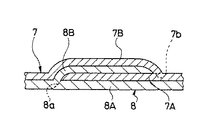
本発明では、上記のような構成の空気入りタイヤにおいて、図2に示すように、インナーライナー層8のタイヤ周方向の一端8aをその他端部8B側に接続し、インナーライナー層8をタイヤ周方向に連続する層に形成してある。タイゴム層7も、そのタイヤ周方向の他端7bをその一端部7A側に接続し、タイヤ周方向に連続する層になっている。
【0012】
インナーライナー層8の他端部8B(一端8aが接続した箇所よりエッジ側)は、タイゴム層7の一端部7Aと他端部7Bの間に介在している。タイゴム層7の一端部7A(他端7bが接続した箇所よりエッジ側)は、インナーライナー層8の一端部8Aと他端部8Bの間に位置している。
このようにインナーライナー層8及びタイゴム層7をそれぞれ接続してタイヤ周方向に連続する層に形成するため、走行時にタイヤに大きな繰り返し変形が作用しても、接合部において同じゴム物性を有するゴム層同志が接続した状態になっているので、クラックが発生することがない。しかも、従来のようなクラック防止用のテープを使用することなく、クラックを抑えることができるので、部品点数の増加によるコストアップなどを来すこともない。
【0013】
上記の空気入りタイヤは、未加硫のインナーライナー層とタイゴム層とを予め貼り合わせた合わせシートを用いて製造される。その合わせシートXはそのタイヤ周方向両端面がシート長手方向に対する傾斜角度αを15〜30°の範囲で同方向に揃って傾斜させた傾斜面X1,X2に形成されている。
その合わせシートXを未加硫のインナーライナー層8’を内周側にして成形ドラム上に巻き付け、その両端部X3,X4を重ね合わせにより接合する時に、図3に示すように、傾斜面X1,X2の鋭角部X5側を対面外側に位置させて接合する。
【0014】
その後、図4に示すように、両傾斜面X1,X2を対面する合わせシート表面X6に、図5のような圧着ローラRを用いて圧着する。これにより、未加硫のインナーライナー層8’のタイヤ周方向の一端8’aが他端部8’B側に接続される。また、未加硫のタイゴム層7’のタイヤ周方向の他端7’bがその一端部7’A側に接続され、未加硫のインナーライナー層8’とタイゴム層7’はそれぞれタイヤ周方向に連続する層になる。この圧着は、合わせシートXを図3のように接合した後、未加硫のカーカス層をその上に巻き付けてから行うようにしてもよい。
【0015】
カーカス層を巻回して、合わせシートXの両傾斜面X1,X2を圧着状態にした後は、通常の公知の工程で行うことができる。例えば、カーカス層の両端部上に未加硫のビードフィラーを外周に取付けたビードコアをセットし、両端部をビードコアの周りに折り返した後、成形ドラムを拡張(リフト)させ、その拡張したカーカス層上に補強コードをタイヤ周方向に対して傾斜させた未加硫のベルト層をその補強コードが交差するように貼り合わせる。トレッドゴム(クラウン部、ショルダー部、及びバットレス部に配置)とサイドゴム(サイドウォール部及びビード部に配置)を順次貼着し、その成型されたグリーンタイヤを加硫成形することにより、図1に示す本発明の空気入りタイヤを得ることができる。
【0016】
上記傾斜角度αが15°よりも小さいと、合わせシートXの両端面をその傾斜角度に切断することができない。逆に30°を越えるとクラックの発生を抑えることが困難になる。傾斜角度αは、合わせシートXにおける切断を容易にするため、21〜30°が好ましい。
図6に合わせシートXの両端面を傾斜面に切断するカッターの一例を示す。このカッターKは、横向きにしたV字の刃部K1を有している。V字の対面する両刃K2は、カッターKの長手方向(水平方向)に対してそれぞれ約8°の角度に形成され、小角度の鋭角状になっている。このようなカッターを用いることにより、合わせシートXの両端面を上記角度を有する傾斜面X1,X2に容易に形成することができる。
【0017】
本発明は、特に上述したライトトラックやそれ以上の重量を有する車両に装着される重荷重用空気入りタイヤに好ましく用いることができる。
【0018】
【実施例】
タイヤサイズを700R15 8PRで共通にし、図1に示す構成の空気入りタイヤにおいて、表1のように合わせシートの傾斜角度αを変えた本発明タイヤ1,2,3と比較タイヤ、傾斜角度αを90°にした従来タイヤ1、及びその従来タイヤ1において、合わせシートの接合部にクラック防止用テープを設けた従来タイヤ2とをそれぞれ各3本作製した。
【0019】
これら各試験タイヤをリムサイズ15×1/2Kのリムに装着し、空気(60%酸素、40%空気)圧を450kPa にし、以下に示す測定条件により、接合部に発生するクラックの評価試験を行ったところ、表1に示す結果を得た。
クラック評価試験
各試験タイヤをドラム径1707mmのドラム試験機に取り付け、負荷荷重13kN、時速50km/h、周囲温度38±3℃の条件下で、12000km走行させた後、インナーライナー層の接合部でのクラックトータル長さを測定し、各3本の平均結果を4段階評価した。Aはクラックトータル長さLが0mm、Bは0mm<L≦5mm、Cは5mm<L≦50mm、Dは50mm<Lを示す。
【0020】
【表1】

表1から明らかなように、本発明タイヤは、クラック防止用テープを設けることなく、そのテープを設けた従来タイヤ2以上にクラックの発生を抑えることができるのが判る。なお、傾斜角度を15°よりも小さくした(10°)傾斜面を有する合わせシートを形成しようとしたが、不可能であった。
【0022】
【発明の効果】
上述したように本発明は、インナーライナー層のタイヤ周方向の一端をその他端部側に接続する一方、タイゴム層のタイヤ周方向の他端をその一端部側に接続し、インナーライナー層及びタイゴム層をタイヤ周方向に連続する層にそれぞれ形成するため、クラック防止用のテープを用いることなく、インナーライナー層の接合部に発生するクラックを抑制することができる。
【図面の簡単な説明】
【図1】本発明の空気入りタイヤの一例を示すタイヤ子午線半断面図である。
【図2】インナーライナー層とタイゴム層の端末部における加硫後タイヤの接合状態を示す断面図である。
【図3】本発明の空気入りタイヤの製造方法において、合わせシートの端末部を接合した状態を示す断面図である。
【図4】合わせシートの両傾斜面を圧着した状態を示す断面図である。
【図5】合わせシートの傾斜面を圧着するのに好ましく使用することができる圧着ローラの一例を示す要部正面図である。
【図6】合わせシートの両端面を傾斜面に形成するのに好ましく使用できるカッターの一例を示す要部正面図である。
【図7】従来のインナーライナー層とタイゴム層の端末部における接合状態を示す断面図である。
【符号の説明】
1 トレッド部 2 ビード部
3 サイドウォール部 4 カーカス層
7 タイゴム層 7A 一端部
7B 他端部 7b 他端
8 インナーライナー層 8A 一端部
8B 他端部 8a 一端
7’未加硫のタイゴム層 8’未加硫のインナーライナー層
X 合わせシート X1,X2 傾斜面
X3,X4 両端部 X5 鋭角部
X6 合わせシート表面 α 傾斜角度[0001]
TECHNICAL FIELD OF THE INVENTION
The present invention relates to a pneumatic tire provided with an inner liner layer inside the tire and a method for manufacturing the same, and more specifically, to prevent cracks occurring at a joint portion of the inner liner layer without using a crack preventing tape. And a method for manufacturing the same.
[0002]
[Prior art]
In a tubeless tire, an inner liner layer made of a non-permeable rubber mainly composed of highly airtight butyl rubber is provided on the inner peripheral surface of the tire in order to maintain a constant air pressure. However, when the butyl rubber constituting the inner liner layer comes into contact with the reinforcing cord of the carcass layer, it causes peeling during the contact. Therefore, a tie rubber layer made of the same rubber as the carcass layer is generally provided between the inner liner layer and the carcass layer to ensure that both are separated from each other.
[0003]
Conventionally, when a tire is manufactured, for example, as shown in FIG. 7, an unvulcanized
However, when the different types of rubber layers are connected to each other in this way, when the tire repeatedly undergoes large deformation due to the difference in the rubber physical properties, the connected
[0004]
Therefore, as a countermeasure, there is a proposal to suppress the occurrence of cracks by attaching a
[0005]
[Problems to be solved by the invention]
An object of the present invention is to provide a pneumatic tire and a method of manufacturing the pneumatic tire that can prevent a crack from occurring at a joint portion of an inner liner layer without using a tape for preventing cracks.
[0006]
[Means for Solving the Problems]
The pneumatic tire of the present invention that achieves the above object is, in a pneumatic tire provided with an inner liner layer via a tie rubber layer on the inner peripheral side of a carcass layer, wherein the inner liner layer has one end in the tire circumferential direction. While the tie rubber layer is formed in a continuous layer in the tire circumferential direction by being connected to an end portion side, the tie rubber layer is formed in a continuous layer by connecting the other end in the tire circumferential direction to one end thereof , and the inner liner is formed. The other end of the layer is interposed between one end and the other end of the tie rubber layer, and one end of the tie rubber layer is interposed between one end and the other end of the inner liner layer. Features.
[0007]
Further, the manufacturing method of the pneumatic tire of the present invention, when manufacturing a pneumatic tire using a laminated sheet in which an unvulcanized inner liner layer and a tie rubber layer are bonded in advance, the tire circumferential direction of the laminated sheet When both end surfaces are formed in an inclined surface inclined in the same direction within a range of 15 to 30 °, and when both ends of the laminated sheet are joined by overlapping with the inner liner layer on the inner peripheral side, an acute angle portion of the inclined surface is formed. After joining with the side positioned outside the facing surface, both inclined surfaces are pressure-bonded to the facing mating sheet surface.
[0008]
As described above, in the present invention, since the inner liner layer and the tie rubber layer are formed on the connected layers extending continuously in the tire circumferential direction, and the discontinuous portions as in the related art are not provided, the present invention has a large Even if the tire is repeatedly deformed, it is possible to suppress the occurrence of cracks at the joint. In addition, since a crack preventing tape used in the related art is not required, the cost does not increase due to an increase in the number of components.
[0009]
BEST MODE FOR CARRYING OUT THE INVENTION
Hereinafter, the configuration of the present invention will be described in detail with reference to the accompanying drawings.
FIG. 1 shows an example of a pneumatic tire used for a light truck as an example of the pneumatic tire of the present invention. 1 is a tread part, 2 is a bead part, 3 is a side wall part. Left and right sidewall portions 3 are extended outwardly in the tire radial direction in connection with the left and
[0010]
Two carcass layers 4 are provided inside the tire. The carcass layer 4 can be arranged in one to three layers in a pneumatic tire for a light truck, and at least one layer may be provided.
[0011]
An
In the present invention, in the pneumatic tire configured as described above, as shown in FIG. 2, one
[0012]
The
As described above, since the
[0013]
The pneumatic tire is manufactured using a laminated sheet in which an unvulcanized inner liner layer and a tie rubber layer are bonded in advance. The laminated sheet X is formed on inclined surfaces X1 and X2 in which both end surfaces in the tire circumferential direction are inclined in the same direction at an inclination angle α of 15 to 30 ° with respect to the sheet longitudinal direction.
When the laminated sheet X is wound around a forming drum with the unvulcanized inner liner layer 8 'on the inner peripheral side, and the both ends X3 and X4 are joined by overlapping, as shown in FIG. , X2 with the acute angle portion X5 side positioned outside the facing surface.
[0014]
Thereafter, as shown in FIG. 4, the sheet is pressed on a mating sheet surface X6 facing both inclined surfaces X1 and X2 using a pressing roller R as shown in FIG. As a result, one end 8'a of the unvulcanized inner liner layer 8 'in the tire circumferential direction is connected to the other end 8'B. The other end 7'b of the unvulcanized tie rubber layer 7 'in the tire circumferential direction is connected to one end 7'A side, and the unvulcanized inner liner layer 8' and the tie rubber layer 7 'are respectively connected to the tire circumference. It becomes a layer continuous in the direction. This pressure bonding may be performed after bonding the laminated sheet X as shown in FIG. 3 and then winding an unvulcanized carcass layer thereon.
[0015]
After the carcass layer is wound and the two inclined surfaces X1 and X2 of the laminated sheet X are brought into a pressure-bonded state, it can be performed by a usual known process. For example, a bead core having an unvulcanized bead filler attached to the outer periphery is set on both ends of the carcass layer, and both ends are turned around the bead core. Then, the forming drum is expanded (lifted), and the expanded carcass layer is expanded. An unvulcanized belt layer in which the reinforcing cords are inclined with respect to the tire circumferential direction is stuck thereon so that the reinforcing cords intersect. The tread rubber (located at the crown, shoulder, and buttress) and the side rubber (located at the sidewall and bead) are sequentially adhered, and the molded green tire is vulcanized to obtain the structure shown in FIG. The pneumatic tire of the present invention shown in the figure can be obtained.
[0016]
If the inclination angle α is smaller than 15 °, both end surfaces of the laminated sheet X cannot be cut to the inclination angle. Conversely, if it exceeds 30 °, it becomes difficult to suppress the occurrence of cracks. The inclination angle α is preferably 21 to 30 ° in order to facilitate cutting the laminated sheet X.
FIG. 6 shows an example of a cutter for cutting both end surfaces of the matching sheet X into inclined surfaces. This cutter K has a V-shaped blade portion K1 oriented horizontally. The two facing blades K2 of the V-shape are each formed at an angle of about 8 ° with respect to the longitudinal direction (horizontal direction) of the cutter K, and have a small acute angle. By using such a cutter, both end surfaces of the laminated sheet X can be easily formed on the inclined surfaces X1 and X2 having the above angles.
[0017]
The present invention can be preferably used particularly for the heavy-duty pneumatic tire mounted on the above-described light truck or a vehicle having a higher weight.
[0018]
【Example】
In the pneumatic tire having the configuration shown in FIG. Three conventional tires 1 each having a 90 ° angle and three
[0019]
Each of the test tires was mounted on a rim having a rim size of 15 × 1 / K, the air (60% oxygen, 40% air) pressure was set to 450 kPa, and an evaluation test of cracks generated at the joint was performed under the following measurement conditions. As a result, the results shown in Table 1 were obtained.
Crack evaluation test Each test tire was mounted on a drum testing machine having a drum diameter of 1707 mm, and after running for 12,000 km under the conditions of a load load of 13 kN, an hourly speed of 50 km / h, and an ambient temperature of 38 ± 3 ° C., at the joint of the inner liner layer Was measured, and the average result of each of the three cracks was evaluated in four steps. A indicates that the total crack length L is 0 mm, B indicates 0 mm <L ≦ 5 mm, C indicates 5 mm <L ≦ 50 mm, and D indicates 50 mm <L.
[0020]
[Table 1]
As is clear from Table 1, it can be seen that the tire of the present invention can suppress the occurrence of cracks more than the
[0022]
【The invention's effect】
As described above, the present invention connects the one end in the tire circumferential direction of the inner liner layer to the other end side, and connects the other end in the tire circumferential direction of the tie rubber layer to one end side thereof. Since the layers are formed in layers that are continuous in the tire circumferential direction, cracks generated at the joint of the inner liner layer can be suppressed without using a tape for preventing cracks.
[Brief description of the drawings]
FIG. 1 is a half sectional view of a tire meridian showing an example of a pneumatic tire of the present invention.
FIG. 2 is a cross-sectional view showing a bonded state of a vulcanized tire at an end portion of an inner liner layer and a tie rubber layer.
FIG. 3 is a cross-sectional view showing a state where the terminal portions of the laminated sheet are joined in the method of manufacturing a pneumatic tire according to the present invention.
FIG. 4 is a cross-sectional view showing a state where both inclined surfaces of the laminated sheet are pressed.
FIG. 5 is a front view of an essential part showing an example of a pressure roller that can be preferably used for pressure-bonding an inclined surface of a laminated sheet.
FIG. 6 is a main part front view showing an example of a cutter which can be preferably used to form both end surfaces of the laminated sheet on inclined surfaces.
FIG. 7 is a cross-sectional view showing a conventional joint state of an inner liner layer and a tie rubber layer at a terminal portion.
[Explanation of symbols]
Reference Signs List 1
Claims (2)
Priority Applications (1)
| Application Number | Priority Date | Filing Date | Title |
|---|---|---|---|
| JP29062696A JP3568334B2 (en) | 1996-10-31 | 1996-10-31 | Pneumatic tire and method of manufacturing the same |
Applications Claiming Priority (1)
| Application Number | Priority Date | Filing Date | Title |
|---|---|---|---|
| JP29062696A JP3568334B2 (en) | 1996-10-31 | 1996-10-31 | Pneumatic tire and method of manufacturing the same |
Publications (2)
| Publication Number | Publication Date |
|---|---|
| JPH10129208A JPH10129208A (en) | 1998-05-19 |
| JP3568334B2 true JP3568334B2 (en) | 2004-09-22 |
Family
ID=17758426
Family Applications (1)
| Application Number | Title | Priority Date | Filing Date |
|---|---|---|---|
| JP29062696A Expired - Fee Related JP3568334B2 (en) | 1996-10-31 | 1996-10-31 | Pneumatic tire and method of manufacturing the same |
Country Status (1)
| Country | Link |
|---|---|
| JP (1) | JP3568334B2 (en) |
Cited By (1)
| Publication number | Priority date | Publication date | Assignee | Title |
|---|---|---|---|---|
| US8363217B2 (en) | 2009-11-04 | 2013-01-29 | Ricoh Company, Ltd. | Spectrometric measurement apparatus, image evaluation apparatus, and image forming apparatus |
Families Citing this family (10)
| Publication number | Priority date | Publication date | Assignee | Title |
|---|---|---|---|---|
| KR20030008804A (en) * | 2001-07-20 | 2003-01-29 | 금호산업 주식회사 | Joint Structure for Tire inner Line |
| JP5114105B2 (en) * | 2007-06-21 | 2013-01-09 | 東洋ゴム工業株式会社 | Manufacturing method of rubber member for tire |
| JP5870975B2 (en) * | 2010-12-22 | 2016-03-01 | 横浜ゴム株式会社 | Pneumatic tire and method for manufacturing pneumatic tire |
| JP5423732B2 (en) * | 2010-12-22 | 2014-02-19 | 横浜ゴム株式会社 | Pneumatic tire |
| JP5810646B2 (en) * | 2011-06-09 | 2015-11-11 | 横浜ゴム株式会社 | Pneumatic tire |
| JP5570487B2 (en) | 2011-10-12 | 2014-08-13 | 住友ゴム工業株式会社 | Pneumatic tire |
| JP5887868B2 (en) * | 2011-11-22 | 2016-03-16 | 横浜ゴム株式会社 | Pneumatic tire manufacturing method |
| JP2015123935A (en) * | 2013-12-27 | 2015-07-06 | 住友ゴム工業株式会社 | Pneumatic tire |
| JP6024697B2 (en) * | 2014-04-04 | 2016-11-16 | 横浜ゴム株式会社 | Pneumatic tire manufacturing method |
| CN107074019A (en) * | 2014-10-15 | 2017-08-18 | 横滨橡胶株式会社 | Pneumatic tire |
-
1996
- 1996-10-31 JP JP29062696A patent/JP3568334B2/en not_active Expired - Fee Related
Cited By (1)
| Publication number | Priority date | Publication date | Assignee | Title |
|---|---|---|---|---|
| US8363217B2 (en) | 2009-11-04 | 2013-01-29 | Ricoh Company, Ltd. | Spectrometric measurement apparatus, image evaluation apparatus, and image forming apparatus |
Also Published As
| Publication number | Publication date |
|---|---|
| JPH10129208A (en) | 1998-05-19 |
Similar Documents
| Publication | Publication Date | Title |
|---|---|---|
| US8900389B2 (en) | Method for producing pneumatic tire | |
| JP3825884B2 (en) | Pneumatic tire manufacturing method | |
| JP3568334B2 (en) | Pneumatic tire and method of manufacturing the same | |
| US20120118464A1 (en) | Puncture sealant laminate | |
| JP4184669B2 (en) | Pneumatic tire and manufacturing method thereof | |
| JPH0481938B2 (en) | ||
| US6109322A (en) | Laminate composite structure for making an unvulcanized carcass for a radial ply tire as an intermediate article of manufacture | |
| JP2005238759A (en) | Pneumatic tire and its manufacturing method | |
| JP2000502294A (en) | Unvulcanized non-cord reinforced subassembly for incorporation into a tire envelope | |
| JP2004009666A (en) | Pneumatic radial tire for aircraft and its manufacturing method | |
| JP3811536B2 (en) | Pneumatic tire manufacturing method | |
| JP2002052909A (en) | Heavy load radial tire | |
| JP2002211208A (en) | Pneumatic radial tire for aircraft | |
| JPH1142909A (en) | Pneumatic radial tire and its manufacture | |
| JP2003094913A (en) | Run-flat tire for winter season and method of manufacturing it | |
| JPH07329065A (en) | Pneumatic tire and manufacture thereof | |
| JPH04962Y2 (en) | ||
| JP4893321B2 (en) | Pneumatic tire manufacturing method | |
| JP3588319B2 (en) | Pneumatic tire | |
| JP6660254B2 (en) | Tire repair methods and repaired tires | |
| CA2145789C (en) | Pneumatic tire and an unvulcanized carcass as an intermediate article in its manufacture | |
| JPH10193926A (en) | Pneumatic tire | |
| JP3708676B2 (en) | Heavy duty radial tire and manufacturing method thereof | |
| JP4634782B2 (en) | Pneumatic tire manufacturing method | |
| JP2000198325A (en) | Pneumatic tire and manufacture thereof |
Legal Events
| Date | Code | Title | Description |
|---|---|---|---|
| A977 | Report on retrieval |
Free format text: JAPANESE INTERMEDIATE CODE: A971007 Effective date: 20040205 |
|
| A131 | Notification of reasons for refusal |
Free format text: JAPANESE INTERMEDIATE CODE: A131 Effective date: 20040302 |
|
| A521 | Written amendment |
Free format text: JAPANESE INTERMEDIATE CODE: A523 Effective date: 20040420 |
|
| TRDD | Decision of grant or rejection written | ||
| A01 | Written decision to grant a patent or to grant a registration (utility model) |
Free format text: JAPANESE INTERMEDIATE CODE: A01 Effective date: 20040608 |
|
| A61 | First payment of annual fees (during grant procedure) |
Free format text: JAPANESE INTERMEDIATE CODE: A61 Effective date: 20040615 |
|
| R150 | Certificate of patent or registration of utility model |
Free format text: JAPANESE INTERMEDIATE CODE: R150 |
|
| R250 | Receipt of annual fees |
Free format text: JAPANESE INTERMEDIATE CODE: R250 |
|
| FPAY | Renewal fee payment (event date is renewal date of database) |
Free format text: PAYMENT UNTIL: 20080625 Year of fee payment: 4 |
|
| FPAY | Renewal fee payment (event date is renewal date of database) |
Free format text: PAYMENT UNTIL: 20090625 Year of fee payment: 5 |
|
| FPAY | Renewal fee payment (event date is renewal date of database) |
Free format text: PAYMENT UNTIL: 20090625 Year of fee payment: 5 |
|
| FPAY | Renewal fee payment (event date is renewal date of database) |
Free format text: PAYMENT UNTIL: 20100625 Year of fee payment: 6 |
|
| FPAY | Renewal fee payment (event date is renewal date of database) |
Free format text: PAYMENT UNTIL: 20100625 Year of fee payment: 6 |
|
| FPAY | Renewal fee payment (event date is renewal date of database) |
Free format text: PAYMENT UNTIL: 20110625 Year of fee payment: 7 |
|
| FPAY | Renewal fee payment (event date is renewal date of database) |
Free format text: PAYMENT UNTIL: 20110625 Year of fee payment: 7 |
|
| FPAY | Renewal fee payment (event date is renewal date of database) |
Free format text: PAYMENT UNTIL: 20110625 Year of fee payment: 7 |
|
| FPAY | Renewal fee payment (event date is renewal date of database) |
Free format text: PAYMENT UNTIL: 20120625 Year of fee payment: 8 |
|
| FPAY | Renewal fee payment (event date is renewal date of database) |
Free format text: PAYMENT UNTIL: 20120625 Year of fee payment: 8 |
|
| FPAY | Renewal fee payment (event date is renewal date of database) |
Free format text: PAYMENT UNTIL: 20130625 Year of fee payment: 9 |
|
| FPAY | Renewal fee payment (event date is renewal date of database) |
Free format text: PAYMENT UNTIL: 20130625 Year of fee payment: 9 |
|
| FPAY | Renewal fee payment (event date is renewal date of database) |
Free format text: PAYMENT UNTIL: 20130625 Year of fee payment: 9 |
|
| R250 | Receipt of annual fees |
Free format text: JAPANESE INTERMEDIATE CODE: R250 |
|
| R250 | Receipt of annual fees |
Free format text: JAPANESE INTERMEDIATE CODE: R250 |
|
| LAPS | Cancellation because of no payment of annual fees |