JP3565099B2 - Endoscope fluid supply device - Google Patents
Endoscope fluid supply device Download PDFInfo
- Publication number
- JP3565099B2 JP3565099B2 JP21828599A JP21828599A JP3565099B2 JP 3565099 B2 JP3565099 B2 JP 3565099B2 JP 21828599 A JP21828599 A JP 21828599A JP 21828599 A JP21828599 A JP 21828599A JP 3565099 B2 JP3565099 B2 JP 3565099B2
- Authority
- JP
- Japan
- Prior art keywords
- passage
- fluid supply
- fluid
- flow path
- valve
- Prior art date
- Legal status (The legal status is an assumption and is not a legal conclusion. Google has not performed a legal analysis and makes no representation as to the accuracy of the status listed.)
- Expired - Fee Related
Links
Images


Classifications
-
- A—HUMAN NECESSITIES
- A61—MEDICAL OR VETERINARY SCIENCE; HYGIENE
- A61B—DIAGNOSIS; SURGERY; IDENTIFICATION
- A61B1/00—Instruments for performing medical examinations of the interior of cavities or tubes of the body by visual or photographical inspection, e.g. endoscopes; Illuminating arrangements therefor
- A61B1/00064—Constructional details of the endoscope body
- A61B1/00066—Proximal part of endoscope body, e.g. handles
- A61B1/00068—Valve switch arrangements
-
- A—HUMAN NECESSITIES
- A61—MEDICAL OR VETERINARY SCIENCE; HYGIENE
- A61B—DIAGNOSIS; SURGERY; IDENTIFICATION
- A61B1/00—Instruments for performing medical examinations of the interior of cavities or tubes of the body by visual or photographical inspection, e.g. endoscopes; Illuminating arrangements therefor
- A61B1/12—Instruments for performing medical examinations of the interior of cavities or tubes of the body by visual or photographical inspection, e.g. endoscopes; Illuminating arrangements therefor with cooling or rinsing arrangements
- A61B1/121—Instruments for performing medical examinations of the interior of cavities or tubes of the body by visual or photographical inspection, e.g. endoscopes; Illuminating arrangements therefor with cooling or rinsing arrangements provided with means for cleaning post-use
- A61B1/125—Instruments for performing medical examinations of the interior of cavities or tubes of the body by visual or photographical inspection, e.g. endoscopes; Illuminating arrangements therefor with cooling or rinsing arrangements provided with means for cleaning post-use using fluid circuits
Landscapes
- Health & Medical Sciences (AREA)
- Life Sciences & Earth Sciences (AREA)
- Surgery (AREA)
- Biomedical Technology (AREA)
- Medical Informatics (AREA)
- Optics & Photonics (AREA)
- Pathology (AREA)
- Radiology & Medical Imaging (AREA)
- Biophysics (AREA)
- Engineering & Computer Science (AREA)
- Physics & Mathematics (AREA)
- Heart & Thoracic Surgery (AREA)
- Nuclear Medicine, Radiotherapy & Molecular Imaging (AREA)
- Molecular Biology (AREA)
- Animal Behavior & Ethology (AREA)
- General Health & Medical Sciences (AREA)
- Public Health (AREA)
- Veterinary Medicine (AREA)
- Endoscopes (AREA)
- Instruments For Viewing The Inside Of Hollow Bodies (AREA)
Description
【0001】
【発明の属する技術分野】
本発明は、内視鏡の流体供給装置に関するものであり、特に観察窓の洗浄を行うためのノズルと、直噴射口とを備え、ノズルから所望の圧力で洗浄液を噴出させ、また直噴射口から所望の流体を噴出させることができるようにした流体供給装置に関するものである。
【0002】
【従来の技術】
一般に、内視鏡の流体供給装置としては、挿入部の先端に設けた観察窓に装着したレンズ面が体液等で汚損された時に、この観察窓に洗浄液を供給し、次いで加圧エアを供給するようにしたレンズ面洗浄装置がある。このレンズ面洗浄装置は、周知のように、観察窓に向けて開口するノズルに、送液流路及び送気流路を接続して設け、これら送液流路及び送気流路への流体の供給を制御するために、挿入部に連設した本体操作部に制御バルブが設けられる。このレンズ面洗浄に加えて、他の流体を体内に供給する必要もある。例えば、体腔内壁に体液なり汚物なりが付着していると、内視鏡による観察が困難になり、また甚だしい場合には、観察不能となることもある。レンズ面洗浄用のノズルはレンズ面に対して所定角度、つまり観察窓からの視野方向に対して交差する方向に向いているので、この方向から洗浄液を噴射しても、観察しようとする体腔内壁に洗浄液を噴射させることはできない。このために、観察窓による観察視野方向に向けて液体を噴射させる直噴射口として、所謂ジェット噴射口を形成するのが一般的である。
【0003】
ジェット噴射口に液体を供給するために、このジェット噴射口に接続した流体供給通路を本体操作部にまで延在させ、この本体操作部に設けた流体圧送手段接続部に接続する構成となし、そして流体圧送手段接続部にはシリンジ等の流体圧送手段が着脱可能に接続されるようになっている。従って、この流体圧送手段接続部に、例えば外筒と、この外筒内に摺動可能に設けたピストンと、このピストンを外筒内で摺動させる内筒とを有するシリンジを接続して、このシリンジのピストンを外筒内に押し込むことによって、内部の液体等をジェット噴射口に向けて圧送できるようになっている。
【0004】
ところで、ジェット噴射させるためには、シリンジ等の流体圧送手段を操作しなければならないが、その操作は、通常、手動で行われることになる。ただし、内視鏡の本体操作部を把持してその操作を行う術者等が流体圧送手段の操作をするのは実質的に不可能であり、このために操作に当っては介助者が必要となる。そこで、ジェット噴射を介助者を必要とすることなく行えるようにするために、レンズ面洗浄用の洗浄液をジェット噴射口側にも流すことができる構成としたものが、例えば実開平6−68717号公報に示されている。
【0005】
この公知の流体供給装置は、本体操作部に3方口弁を設けて、送液源側の通路と、ノズル側の通路及びジェット噴射口側の通路の2つの通路とを3方口弁のケーシングに開口させている。そして、この3方口弁の弁体は本体操作部に所定角度往復回動可能に装着されており、この弁体を回動させることによって、送液源側の通路を、ノズル側の通路に連通する状態と、ジェット噴射口側に連通する状態とに切り換わるようになる。その結果、例えば体腔内壁に汚損物が付着している際には、この3方口弁の弁体を回動させて、制御バルブを操作することにより送液源側から供給される洗浄液がジェット噴射口に供給される。また、体腔内壁から汚損物が除去されると、3方口弁の弁体を回動させて、送液源側とノズル側とを接続する状態に戻すことによって、通常のレンズ面洗浄が行える状態に復帰する。さらに、体腔内壁に付着している汚損物を有効に除去するには、レンズ面洗浄の場合と比較して、それより高い圧力が必要となるから、前述した従来技術においては、送液源からの洗浄液の供給圧力を高めるようにしている。
【0006】
【発明が解決しようとする課題】
ところで、前述した2つの態様の洗浄液供給の条件は必ずしも同じではない。即ち、レンズ面に付着する汚損物は、体腔内壁に付着している汚損物を取り除く際と比較した時に、より低圧で少量の洗浄液を供給するだけで容易に除去できる場合が多い。しかも、レンズ面は頻繁に汚損されるから、操作中は繰り返しレンズ面洗浄が行われることになる。レンズ面洗浄にとって必要以上の高圧で洗浄液を供給することは、それだけ流量も多くなり、このために患者に対する苦痛が増大することになる。レンズ面洗浄を行う際には、洗浄液の量は必要最小限に抑制しなければならない。これに対して、ジェット噴射時にはある程度の高圧が必要となり、従ってレンズ面洗浄と体腔内壁の洗浄とでは、洗浄液の供給圧及び供給量を異ならせる必要があり、同一の送液源を使用するのは必ずしも望ましくはない場合がある。一方、レンズ面に付着する汚損物の状態等によっては、高圧の洗浄液を噴射させた方が好ましい場合もある。このために、レンズ面洗浄を行う際に、必要に応じて、洗浄液を高圧で噴射させることができるように選択できるようになっておれば、さらに望ましい。
【0007】
また、体腔内壁に向けて供給される流体は、前述した洗浄液だけでなく、例えば体腔内壁に色素剤等を散布したり、吹き付けたりすることもある。しかしながら、前述したように、ジェット噴射口をレンズ面洗浄用の送液源に接続する構成とした場合には、このジェット噴射口に向けて洗浄液以外の流体を供給できなくなってしまう。従って、色素散布や薬液噴霧等を行うには、さらに別の流体供給経路を設けなければならなくなる。
【0008】
本発明は以上の点に鑑みてなされたものであって、その目的とするところは、観察窓及びジェット噴射口に向けて所望の圧力及び流量で所望の流体を供給できるようにすることにある。
【0009】
【課題を解決するための手段】
前述した目的を達成するために、本発明は、挿入部の先端部本体に、観察窓に向けて少なくとも洗浄液を噴出する第1の流体供給通路が接続されたノズルと、第2の流体供給通路が接続され、前記挿入部の延長線方向に向けて流体を噴射する直噴射口とを設け、また本体操作部内には、第1の流体供給通路の他端が接続される制御バルブと、前記第2の流体供給通路への供給路が形成され、流体圧送手段が着脱可能に接続される流体圧送手段接続部とを設けた内視鏡の流体制御装置であって、前記第1の流体供給通路はノズル側流路とバルブ側流路とに分ける切換通路を設け、この切換通路に前記供給路を、切換通路側から供給路側への逆流を防止する逆流防止弁を介して接続され、前記切換通路は、前記第1の流体供給通路におけるノズル側流路とバルブ側流路とが接続し、かつ前記供給路を前記第2の流体供給通路と遮断した状態と、この第1の流体供給通路のノズル側流路とバルブ側流路とを遮断し、かつ前記供給路を前記第2の流体供給通路に通じる状態とに切換可能な構成としたことをその特徴とするものである。
【0010】
ここで、流体圧送手段接続部としては、例えば、本体操作部に装着され、第1の流体供給通路におけるノズル側流路及びバルブ側流路と、第2の流体供給通路とが接続されるケーシングと、このケーシング内に着脱可能に設けられ、切換通路及び供給路と、その間に介装される逆流防止弁とを備え、流体圧送手段が着脱可能に接続される流体圧送手段接続ユニットとから構成することができる。そして、流体圧送手段接続ユニットは、ケーシング内で所定角度回動させることによって、切換通路を、第1の流体供給通路のノズル側流路とバルブ側流路とが接続され、かつ供給路は第2の流体供給通路と遮断される第1の選択位置と、この第1の流体供給通路のノズル側流路とバルブ側流路とが遮断され、かつ供給路が第2の流体供給通路に通じる第2の選択位置と切り換わるように構成することができる。この場合において、流体圧送手段接続ユニットをケーシングに対してこれら2つの選択位置に係止するクリック手段を備える構成とすると、その操作性が良好となる。しかも、流体圧送手段接続ユニットは、さらにケーシング内で所定長さだけ軸線方向に移動可能となすと共に連通路を設けることによって、第1の流体供給通路を構成するバルブ側流路と第2の流体供給通路とを接続し、かつノズル側通路を遮断する第3の選択位置に切換可能な構成とすれば、4つの態様で流体の供給を行うことができる。
【0011】
【発明の実施の形態】
以下、図面に基づいて本発明の実施の形態を説明する。まず、図1に内視鏡の流体供給装置の概略構成を示す。同図に示したように、内視鏡は、本体操作部1に体腔内等への挿入部2を連設すると共に、この本体操作部1からユニバーサルコード3が引き出されている。挿入部2の先端部本体2aには、レンズ面4(対物レンズまたはそのカバーガラス)を装着した観察窓が装着されており、またこのレンズ面4に向けて洗浄用流体の噴射ノズル5が設けられている。
【0012】
噴射ノズル5には、洗浄水タンク6からの洗浄水と、エアポンプ7からの加圧空気とが供給されるようになっている。そして、これら加圧空気及び洗浄水の供給制御を行うために、本体操作部1には制御バルブ8が設けられている。ここで、制御バルブ8には、大気開放口を設けた操作ボタン8aが設けられており、この操作ボタン8aに手を触れない状態では、エアポンプ7からの空気は大気に開放され、大気開放口を閉鎖すると、加圧空気が供給され、また操作ボタン8aを押し込むと洗浄水タンク6から送水が可能になるように構成されている。なお、この制御バルブ8の構成は周知であるので、その具体的な構成の図示及び説明は省略する。
【0013】
エアポンプ7からの空気配管9は、制御バルブ8に接続されると共に、その途中で洗浄水タンク6を加圧するための加圧空気配管10に分岐している。また、洗浄水タンク6からの送水配管11も制御バルブ8に接続されている。そして、制御バルブ8には、送水流路12と送気流路13とが接続されており、これら送水流路12及び送気流路13は、挿入部2の先端近傍で合流して合流流路14となり、この合流流路14の先端は噴射ノズル5に接続されている。なお、送水流路及び送気流路はそれぞれ独立して噴射ノズルにまで延在させるように構成することもできる。
【0014】
噴射ノズル5はレンズ面4の方向、つまり挿入部2の軸線と交差する方向に向いており、観察窓は挿入部2の延長線方向を観察視野とするものである。観察視野内において、体腔内壁に付着する体液等の汚損物を洗い流したり、また薬液等を吹き付けたりするためには、噴射口は観察視野の方向、つまり挿入部2の延長線方向に向いていなければならない。このために、先端部本体2aには直噴射口としてのジェット噴射口15が挿入部2の延長線方向に向けて開口している。そして、このジェット噴射口15には、レンズ面4の洗浄用とは別系統の流体供給流路16が接続されている。この流体供給流路16は、本体操作部1にまで延在されており、この本体操作部1に設けた補助送液ユニット17に接続されている。また、送水流路12において、本体操作部1内の制御バルブ8の装着位置近傍でこの補助送液部17に接続されており、これによって送水流路12はノズル側流路12aとバルブ側流路12bとに分けられることになる。
【0015】
補助送液部17には、例えば周知のルアーロック機構等により流体圧送手段としてのシリンジ18等が着脱可能に接続されるようになっている。従って、噴射ノズル5に通じる送水流路12が第1の流体供給通路、ジェット噴射口15に通じる流体供給流路16が第2の流体供給通路となる。そして、この補助送液部17は、洗浄水タンク6から供給される洗浄水を送水流路12を介して、噴射ノズル5に供給する状態と、シリンジ18が接続された時に、この送水流路12を介して噴射ノズル5からシリンジ18内の液体を噴射させる状態と、シリンジ18から流体供給流路16を介してジェット噴射口15に液体を噴出させる状態との3つの態様を選択できるようになっている。
【0016】
このために、図2に示したように、本体操作部1のハウジング20には、開口20aが形成されており、かつハウジング20内において、この開口20aに臨むように流路分岐用のケーシング21が装着されている。このケーシング21は、概略有底円筒状の部材からなり、図3及び図4に示したように、送水流路12におけるノズル側流路12aと、バルブ側流路12bとが接続されており、さらに流体供給流路16もこのケーシング21に接続されている。また、ケーシング21には流体圧送手段接続ユニットとして補助送液ユニット22が装着されており、シリンジ18はこの補助送液ユニット22に着脱可能に接続されるようになっている。
【0017】
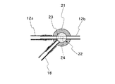
補助送液ユニット22は、その一端側がケーシング21に挿入されており、他端側は本体操作部1のハウジング20の開口20aから外部に導出されるようにして装着されて、所定長さだけ本体操作部1の外方に突出している。そして、この補助送液ユニット22には、そのケーシング21内への挿入側端部近傍に、その軸線と直交する方向に貫通する切換通路23が設けられ、また一端が切換通路23に通じ、他端が補助送液ユニット22の本体操作部1の外側に開口し、流体圧送手段としてのシリンジ18からの液体が流入する供給路24が設けられている。この供給路24は途中で拡径しており、この拡径部分がシリンジ18の接続部24aとなっている。さらに、供給路24における切換通路23への接続部分には、逆流防止弁25が装着されている。この逆流防止弁25は、ゴム板からなる本体板25aにスリット25bを形成し、かつ本体板25aにおける切換通路23に対面する側の面にはスリット25bを閉鎖する方向に作用する舌片部25cを設けたものから構成される。従って、逆流防止弁25は供給路24側から切換通路23側に圧力流体を流すことはできるが、切換通路23側が供給路24側より高圧になったとしても、切換通路23側から供給路24に流体が流れることはない。
【0018】
ここで、補助送液ユニット22はケーシング21内で所定角度往復回動できるようになっており、図3に示した位置では、切換通路23は送水流路12におけるノズル側流路12aとバルブ側流路12bとを連通させ、また切換通路23は流体供給流路16とは連通しない状態となり、これが第1の選択位置である。また、図4に示した位置に回動させると、切換通路23はノズル側流路12aとも、バルブ側流路12bとも連通しない状態、つまり送水流路12における噴射ノズル5と制御バルブ8とが遮断した状態になり、かつ切換通路23は流体供給流路16と連通する状態になって、これが第2の選択位置である。
【0019】
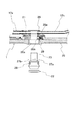
以上の第1,第2の選択位置に補助送液ユニット22を固定的に保持するために、図5に示したように、ケーシング21にはクリックばね26aに付勢されたクリックボール26bからなるクリック部材26が設けられ、また補助送液ユニット22の外周面には2箇所にクリック溝27a,27bが形成されている。従って、クリック部材26のクリックボール26bがクリック溝27aに係合する際には、補助送液ユニット22は第1の選択位置に保持され、またクリック溝27bに係合すると、第2の選択位置に保持されるようになっている。さらに、図6から明らかなように、本体操作部1のハウジング20の表面には、補助送液ユニット22が第1の選択位置となっているか、または第2の選択位置となっているかを表示する指標28a,28bが設けられ、補助送液ユニット22の基準表示部28が指標28aと一致した位置にあるか、または指標28bと一致した位置にあるかによりいずれの選択位置が選択されているかが示される。
【0020】
ここで、補助送液ユニット22は、図7にも示したように、本体操作部1に対して着脱可能に装着されるようになっている。そして、装着状態で安定的に保持し、しかも本体操作部1内に汚損物が入り込まないようにするために、補助送液ユニット22の外周面には、ケーシング21の内面と、本体操作部1のハウジング20における開口20aの周壁との間にシールリング29,29が介装されている。そして、補助送液ユニット22をケーシング21内に挿入した時に、これらシールリング29はある程度撓められた状態になる結果、その弾性力で補助送液ユニット22は本体操作部1から脱落しないように保持される。
【0021】
以上のように構成することによって、洗浄水タンク6から送水流路12を介して噴射ノズル5に洗浄液をエアポンプ7で規定される圧力で洗浄水を圧送する状態と、流体圧送手段としてのシリンジ18から所望の圧力で噴射ノズル5に洗浄水を圧送する状態と、流体供給流路16からジェット噴射口15に所望の種類の流体を、所望の圧力で供給できる状態とのいずれかを選択できるようになる。
【0022】
而して、補助送液ユニット22を図3に示した第1の選択位置に保持すると、送水流路12におけるノズル側流路12aはバルブ側流路12bと切換通路23を介して連通している。また、供給路24は、逆流防止弁25を介してではあるが、切換通路23と接続されている。ただし、制御バルブ8が操作されない限り、この制御バルブ8により送水流路12は送水配管11との連通が遮断されている。また、逆流防止弁25が設けられているので、たとえ送水流路12側の圧力が高くても、送水流路12側から供給路24に逆流が生じることがない状態に保持されている。
【0023】
制御バルブ8の操作ボタン8aを押し込むように操作して、送水配管11と送水流路12とを連通させると、エアポンプ7から加圧空気配管10を介して洗浄水タンク6内に空気圧が導入され、この空気圧に応じた圧力で送水配管11内に洗浄水が供給され、送水配管11から制御バルブ8を介して送水流路12内に流れ込む。ここで、送水流路12におけるバルブ側流路12bは切換通路23を介してノズル側流路12aと連通しているので、送水流路12から合流流路14を経て噴射ノズル5に洗浄水が供給されて、レンズ面4に付着する汚損物を洗い流すことができる。この後に、操作ボタン8aを戻して、送水配管11と送水流路12との接続を遮断し、かつ操作ボタン8aの大気開放口を遮断状態に保持すると、エアポンプ7からの加圧空気が空気配管9から送気流路13に流れるようになり、噴射ノズル5から加圧空気をレンズ面4に吹き付けることができる。これによって、レンズ面4に付着している水滴等を空気圧の作用で取り除くことができる。これによって、レンズ面4が清浄な状態に保たれる。
【0024】
ところで、洗浄水タンク6を洗浄水の供給源とした場合においては、噴射ノズル5から噴射される洗浄水の圧力はエアポンプ7の圧力に依存する。ただし、この圧力では除去できないような頑固な汚れ等がレンズ面4に付着した時には、より高圧の洗浄水を供給する。このために、補助送液ユニット22にシリンジ18を接続し、また制御バルブ8は送水配管11と送水流路12との連通を遮断した状態とする。そして、シリンジ18内には洗浄水を注入しておき、このシリンジ18のピストンを手動操作で押し込むことにより、シリンジ18内の洗浄水が供給路25に供給される。ここで、シリンジ18は手動操作されることから、押圧力を調整することによって、任意の圧力を生じさせることができる。この圧力により逆流防止弁25が開いて、切換通路23から送水流路12内に洗浄水が圧送される。ここで、洗浄水タンク6からの洗浄水を供給した後には、少なくとも送水流路12全体に、またこの送水直後であれば、合流流路14内にも、洗浄水が充満しており、かつバルブ側流路12bの端部は制御バルブ8により遮断されていることから、シリンジ18を操作すると、直ちにその押圧力に応じた圧力で洗浄水が噴射ノズル5から噴射される。この結果、所望の圧力の洗浄水をレンズ面4に噴射させることができ、頑固な汚れ等を確実に除去できる。
【0025】
噴射ノズル8はレンズ面4に洗浄水を供給するものであるが、ジェット噴射口15からは体腔内壁に付着する体液等の汚損物を洗い流すための洗浄水を噴射させることができるが、この洗浄水以外の用途の流体、例えば色素剤を含めた様々な薬液も噴射できるようになっている。このジェット噴射口15に所望の流体を供給する際には、補助送液ユニット22を図4の第2の選択位置に切り換える。この操作は補助送液ユニット22を軸回りに所定角度回動させるだけの操作で良い。この第2の選択位置では、送水流路12におけるノズル側,バルブ側の両流路12a,12bは共に切換通路23との連通が遮断され、切換通路23は流体供給流路16と連通する。勿論、逆流防止弁25の作用により切換通路23と供給路24との連通は断たれており、かつ流体供給流路16内の圧力が高い場合でも、流体供給流路16側から供給路24側への逆流は生じない。
【0026】
例えば、洗浄水や薬液等所望の流体を注入したシリンジ18を補助送液ユニット22に装着する。そして、このシリンジ18を手動操作で加圧すると、シリンジ18内の流体は、その圧力により逆流防止弁25を開いて、供給路24から切換通路23を介して流体供給流路16に供給される。従って、この流体はジェット噴射口15から噴射されることになる。ここで、ジェット噴射口15は、噴射ノズル5とは異なり、挿入部2の延長線方向に向けて流体を噴射させるようになっているので、観察を行っている体腔内壁に向けて確実に洗浄水や薬液等を噴射させることができる。この結果、観察対象となる体腔内壁の洗浄や、検査のための薬液散布を円滑に行える。
【0027】
内視鏡は使用の都度洗浄する必要があり、前述した流体供給装置の内部も完全に洗浄しなければならない。補助送液ユニット22は、切換通路23,供給路24及び逆流防止弁25を一体に組み込んだものであり、しかもケーシング21から容易に脱着できるようになっている。従って、図7に示したように、この補助送液ユニット22を本体操作部1から取り外せば、送水流路12におけるノズル側流路12a,バルブ側流路12bと、流体供給流路16がケーシング21内に開口し、かつこれらの流路内径は全長にわたってほぼ均一になっているので、洗浄用のブラシをケーシング21から各流路に挿入することによって容易に洗浄することができる。なお、送水流路12におけるバルブ側流路12bは流路長が短く、しかも内部が汚損される可能性が少ないので、例えば制御バルブ8への接続側の近傍にこの制御バルブ8側が高圧になった時に流路を開く逆止弁を設けておくことによって、レンズ面4の洗浄時に、制御バルブ8により送水配管11と送水流路12とを連通させたままで、シリンジ18からの洗浄水の供給も行えることになる。
【0028】
次に、図8乃至図10は、本発明の第2の実施の形態を示すものである。この実施の形態においては、前述した第1の実施の形態における3つの態様の流体供給を選択できるのに加えて、さらに洗浄水タンク6からの洗浄水をジェット噴射口15に供給できるようにしたものである。
【0029】
このために、補助送液ユニット122には、供給路124と、切換通路123及びその間に介装した逆流防止弁125を設けると共に、切換通路123を設けた位置より先端側に連通路100を設けるように構成している。また、補助送液ユニット122の外周面における切換通路123の形成位置と連通路100の形成位置との間にはシールリング101が設けられている。一方、ケーシング121には、図9及び図10に示したように、送水流路12におけるノズル側流路12a,バルブ側流路12bと、流体供給流路16が開口しているが、その奥行きは、前述した第1の実施の形態と比較して、補助送液ユニット122に連通路100を設けることにより張り出した分だけ深くなっている。
【0030】
連通路100は送水流路12のバルブ側流路12bと流体供給流路16とを連通させるためのものである。そして、図8に実線で示したように、補助送液ユニット122をケーシング121内に押し込んだ状態では、図9に示したようになり、前述した第1の実施の形態と全く同じ機能を発揮する。そして、補助送液ユニット122を図8に仮想線で示したように、ケーシング121から所定長さだけ引き抜く方向に変位させると、図10に示したように、送水流路12におけるノズル側流路12aはバルブ側流路12bとは遮断した状態に保持されるが、バルブ側流路12bは流体供給流路16と連通路100を介して連通することになる。従って、この状態で制御バルブ8の操作ボタン8aを押し込んで、送水配管11と送水流路12におけるバルブ側流路12bとを連通させると、洗浄水タンク6からの洗浄水が連通路100から流体供給流路16に供給され、ジェット噴射口15から挿入部2の前方、つまり観察窓からの観察視野の方向に向けて噴射される。これによって、シリンジ18を用いなくても、体腔内壁の汚損物を洗い流す作業を行うことができる。
【0031】
【発明の効果】
本発明は以上のように構成したので、観察窓及びジェット噴射口に向けて所望の圧力及び流量で所望の流体を供給できる等の効果を奏する。
【図面の簡単な説明】
【図1】本発明の実施の一形態を示す内視鏡の流体供給装置の概略構成図である。
【図2】補助送液部の構成を示す断面図である。
【図3】図2のX−X断面図である。
【図4】図3とは異なる作動状態を示す断面図である。
【図5】図2のY−Y断面図である。
【図6】図2の矢示方向から見た外観図である。
【図7】補助送液ユニットを脱着した状態を示す図2と同様の断面図である。
【図8】本発明の第2の実施の形態を示す補助送液部の断面図である。
【図9】図8のZ−Z断面図である。
【図10】図9とは異なる作動状態を示す断面図である。
【符号の説明】
1 本体操作部 2 挿入部
4 レンズ面 5 噴射ノズル
6 洗浄水タンク 8 制御バルブ
11 送水配管 12 送水流路
12a ノズル側流路 12b バルブ側流路
15 ジェット噴射口 16 流体供給流路
17 補助送液部 18 シリンジ
20 ハウジング 20a 開口
21,121 ケーシング 22,122 補助送液ユニット
23,123 切換通路 24,124 供給路
25,125 逆流防止弁 26 クリック部材
27a,27b クリック溝 29,101 シールリング
100 連通路[0001]
TECHNICAL FIELD OF THE INVENTION
The present invention relates to a fluid supply device for an endoscope, and in particular, includes a nozzle for cleaning an observation window, and a direct injection port, and jets a cleaning liquid from the nozzle at a desired pressure. The present invention relates to a fluid supply device capable of ejecting a desired fluid from a fluid supply device.
[0002]
[Prior art]
Generally, as a fluid supply device for an endoscope, when a lens surface attached to an observation window provided at the distal end of an insertion portion is contaminated with body fluid or the like, a cleaning liquid is supplied to the observation window, and then pressurized air is supplied. There is a lens surface cleaning device that is designed to perform such cleaning. As is well known, this lens surface cleaning device is provided with a liquid supply flow path and an air supply flow path connected to a nozzle that opens toward an observation window, and supplies a fluid to the liquid supply flow path and the air supply flow path. In order to control the operation, a control valve is provided in a main body operation section connected to the insertion section. In addition to the lens surface cleaning, other fluids need to be supplied into the body. For example, if bodily fluids or contaminants adhere to the inner wall of the body cavity, observation with an endoscope becomes difficult, and in extreme cases, observation becomes impossible. The nozzle for cleaning the lens surface is oriented at a predetermined angle with respect to the lens surface, that is, in a direction intersecting the direction of the field of view from the observation window. The cleaning liquid cannot be sprayed on the surface. For this purpose, a so-called jet outlet is generally formed as a direct outlet for ejecting the liquid in the viewing direction of the viewing window.
[0003]
In order to supply the liquid to the jet injection port, a fluid supply passage connected to the jet injection port is extended to the main body operation section, and is not connected to a fluid pressure feeding means connection section provided in the main body operation section. A fluid pressure feeding means such as a syringe is detachably connected to the fluid pressure feeding means connection portion. Accordingly, a syringe having an outer cylinder, a piston slidably provided in the outer cylinder, and an inner cylinder that slides the piston in the outer cylinder, for example, is connected to the fluid pressure feeding means connection portion, By pushing the piston of the syringe into the outer cylinder, liquid and the like inside can be pressure-fed toward the jet injection port.
[0004]
By the way, in order to perform jet injection, it is necessary to operate a fluid pumping means such as a syringe, but the operation is usually performed manually. However, it is practically impossible for an operator or the like performing the operation by grasping the main body operation unit of the endoscope to operate the fluid pumping means. It becomes. Therefore, in order to enable the jet injection without the need of an assistant, a cleaning liquid for cleaning the lens surface can be supplied to the jet injection port side, for example, Japanese Utility Model Laid-Open No. 6-68717. It is indicated in the gazette.
[0005]
In this known fluid supply device, a three-way valve is provided in a main body operation unit, and a passage on a liquid supply source side and two passages, a passage on a nozzle side and a passage on a jet outlet side, are connected to a three-way valve. It is open to the casing. The valve body of the three-way valve is mounted on the main body operation unit so as to be reciprocally rotatable by a predetermined angle. By rotating the valve body, the passage on the liquid supply source side is changed to the passage on the nozzle side. The state is switched between the state of communication and the state of communication with the jet injection port side. As a result, for example, when contaminants are adhered to the inner wall of the body cavity, the cleaning liquid supplied from the liquid supply source side is jetted by rotating the valve body of the three-way valve and operating the control valve. It is supplied to the injection port. Further, when the contaminants are removed from the inner wall of the body cavity, a normal lens surface cleaning can be performed by rotating the valve body of the three-way valve to return to a state in which the liquid supply source side and the nozzle side are connected. Returns to the state. Further, in order to effectively remove the contaminants adhering to the inner wall of the body cavity, a higher pressure is required as compared with the case of cleaning the lens surface. The supply pressure of the cleaning liquid is increased.
[0006]
[Problems to be solved by the invention]
By the way, the conditions for the supply of the cleaning liquid in the two embodiments described above are not necessarily the same. That is, in many cases, the dirt adhering to the lens surface can be easily removed only by supplying a small amount of the cleaning liquid at a lower pressure as compared with the case of removing the dirt adhering to the inner wall of the body cavity. In addition, since the lens surface is frequently soiled, the lens surface is repeatedly cleaned during the operation. Supplying the cleaning liquid at an unnecessarily high pressure for cleaning the lens surface also increases the flow rate, thereby increasing the pain for the patient. When performing lens surface cleaning, the amount of cleaning liquid must be kept to a minimum. On the other hand, a certain high pressure is required at the time of jetting, so that the supply pressure and the supply amount of the cleaning liquid need to be different between the lens surface cleaning and the cleaning of the inner wall of the body cavity, and the same liquid supply source is used. May not always be desirable. On the other hand, depending on the condition of the contaminants adhering to the lens surface, it may be preferable to spray a high-pressure cleaning liquid. For this reason, it is more desirable that the cleaning liquid can be selected so that the cleaning liquid can be jetted at a high pressure as needed when cleaning the lens surface.
[0007]
Further, the fluid supplied toward the inner wall of the body cavity may be, for example, spraying or spraying a coloring agent or the like on the inner wall of the body cavity in addition to the above-described cleaning liquid. However, as described above, in the case where the jet outlet is connected to the liquid supply source for cleaning the lens surface, it becomes impossible to supply a fluid other than the cleaning liquid to the jet outlet. Therefore, in order to spray a dye, spray a chemical solution, or the like, it is necessary to provide another fluid supply path.
[0008]
The present invention has been made in view of the above points, and an object of the present invention is to enable a desired fluid to be supplied at a desired pressure and flow rate toward an observation window and a jet outlet. .
[0009]
[Means for Solving the Problems]
In order to achieve the above-described object, the present invention provides a nozzle in which a first fluid supply passage for ejecting at least a cleaning liquid toward an observation window is connected to a distal end body of an insertion portion, and a second fluid supply passage. A direct-injection port for injecting fluid in the direction of the extension of the insertion portion is provided, and a control valve to which the other end of the first fluid supply passage is connected in the main body operation portion; A fluid control device for an endoscope, wherein a fluid supply path to a second fluid supply passage is formed, and a fluid pressure supply means connection portion to which a fluid pressure supply means is detachably connected is provided. The passage is provided with a switching passage dividing the nozzle-side passage and the valve-side passage, and the supply passage is connected to the switching passage via a backflow prevention valve for preventing a backflow from the switching passage to the supply passage. The switching passage is a nozzle in the first fluid supply passage. A state in which the flow path and the valve-side flow path are connected, and the supply path is cut off from the second fluid supply path, and the nozzle-side flow path and the valve-side flow path of the first fluid supply path are cut off And the supply passage can be switched to a state in which the supply passage communicates with the second fluid supply passage.
[0010]
Here, as the fluid pressure feeding means connection portion, for example, a casing attached to the main body operation portion and connected to the nozzle side flow path and the valve side flow path in the first fluid supply passage and the second fluid supply passage And a fluid pressure feeding means connection unit, which is detachably provided in the casing, includes a switching passage and a supply path, and a check valve interposed therebetween, and the fluid pressure feeding means is detachably connected. can do. Then, the fluid pressure feeding means connection unit rotates the switching passage by a predetermined angle in the casing, so that the nozzle-side flow path and the valve-side flow path of the first fluid supply path are connected, and the supply path is the second path. A first selected position that is cut off from the second fluid supply passage, the nozzle-side flow passage and the valve-side flow passage of the first fluid supply passage are cut off, and the supply passage communicates with the second fluid supply passage. It can be configured to switch to the second selected position. In this case, operability is improved if the fluid pressure feeding means connection unit is provided with click means for locking the casing at these two selected positions with respect to the casing. In addition, the fluid-pressure-feeding-means connection unit is further provided so as to be movable in the axial direction by a predetermined length in the casing and to provide the communication passage, so that the valve-side flow passage forming the first fluid supply passage and the second fluid If the configuration is such that it can be switched to the third selected position that connects to the supply passage and shuts off the nozzle-side passage, the fluid can be supplied in four modes.
[0011]
BEST MODE FOR CARRYING OUT THE INVENTION
Hereinafter, embodiments of the present invention will be described with reference to the drawings. First, FIG. 1 shows a schematic configuration of a fluid supply device for an endoscope. As shown in FIG. 1, the endoscope has a main
[0012]
The jet nozzle 5 is supplied with cleaning water from a cleaning
[0013]
The
[0014]
The injection nozzle 5 is oriented in the direction of the lens surface 4, that is, in a direction intersecting the axis of the
[0015]
A
[0016]
For this purpose, as shown in FIG. 2, an opening 20 a is formed in the
[0017]
The auxiliary
[0018]
Here, the auxiliary
[0019]
As shown in FIG. 5, the
[0020]
Here, the auxiliary
[0021]
With the above-described configuration, a state in which the cleaning liquid is pumped from the cleaning
[0022]
When the auxiliary
[0023]
When the
[0024]
By the way, when the cleaning
[0025]
The
[0026]
For example, the
[0027]
The endoscope must be cleaned each time it is used, and the inside of the above-described fluid supply device must also be completely cleaned. The auxiliary
[0028]
Next, FIG. 8 to FIG. 10 show a second embodiment of the present invention. In this embodiment, in addition to being able to select the fluid supply of the three aspects in the above-described first embodiment, the washing water from the
[0029]
For this purpose, the auxiliary
[0030]
The
[0031]
【The invention's effect】
Since the present invention is configured as described above, the present invention has an effect that a desired fluid can be supplied at a desired pressure and flow rate toward the observation window and the jet outlet.
[Brief description of the drawings]
FIG. 1 is a schematic configuration diagram of a fluid supply device for an endoscope according to an embodiment of the present invention.
FIG. 2 is a cross-sectional view illustrating a configuration of an auxiliary liquid sending unit.
FIG. 3 is a sectional view taken along line XX of FIG. 2;
FIG. 4 is a cross-sectional view showing an operation state different from FIG.
FIG. 5 is a sectional view taken along line YY of FIG. 2;
FIG. 6 is an external view as viewed from a direction indicated by an arrow in FIG. 2;
FIG. 7 is a sectional view similar to FIG. 2, showing a state where an auxiliary liquid sending unit is detached.
FIG. 8 is a cross-sectional view of an auxiliary liquid sending unit according to a second embodiment of the present invention.
FIG. 9 is a sectional view taken along the line ZZ of FIG. 8;
FIG. 10 is a sectional view showing an operation state different from that of FIG. 9;
[Explanation of symbols]
1
4 Lens surface 5 Injection nozzle
6
11
12a Nozzle
15
17 Auxiliary
20
21, 121
23,123 Switching passage 24,124 Supply passage
25,125
27a,
100 connecting passage
Claims (5)
Priority Applications (2)
| Application Number | Priority Date | Filing Date | Title |
|---|---|---|---|
| JP21828599A JP3565099B2 (en) | 1999-08-02 | 1999-08-02 | Endoscope fluid supply device |
| US09/629,875 US6425535B1 (en) | 1999-08-02 | 2000-08-01 | Fluid supplying apparatus for endoscope |
Applications Claiming Priority (1)
| Application Number | Priority Date | Filing Date | Title |
|---|---|---|---|
| JP21828599A JP3565099B2 (en) | 1999-08-02 | 1999-08-02 | Endoscope fluid supply device |
Publications (2)
| Publication Number | Publication Date |
|---|---|
| JP2001037709A JP2001037709A (en) | 2001-02-13 |
| JP3565099B2 true JP3565099B2 (en) | 2004-09-15 |
Family
ID=16717455
Family Applications (1)
| Application Number | Title | Priority Date | Filing Date |
|---|---|---|---|
| JP21828599A Expired - Fee Related JP3565099B2 (en) | 1999-08-02 | 1999-08-02 | Endoscope fluid supply device |
Country Status (2)
| Country | Link |
|---|---|
| US (1) | US6425535B1 (en) |
| JP (1) | JP3565099B2 (en) |
Families Citing this family (62)
| Publication number | Priority date | Publication date | Assignee | Title |
|---|---|---|---|---|
| US8888688B2 (en) | 2000-04-03 | 2014-11-18 | Intuitive Surgical Operations, Inc. | Connector device for a controllable instrument |
| US6468203B2 (en) | 2000-04-03 | 2002-10-22 | Neoguide Systems, Inc. | Steerable endoscope and improved method of insertion |
| US6610007B2 (en) | 2000-04-03 | 2003-08-26 | Neoguide Systems, Inc. | Steerable segmented endoscope and method of insertion |
| US8517923B2 (en) | 2000-04-03 | 2013-08-27 | Intuitive Surgical Operations, Inc. | Apparatus and methods for facilitating treatment of tissue via improved delivery of energy based and non-energy based modalities |
| JP4538680B2 (en) * | 2000-09-29 | 2010-09-08 | 富士フイルム株式会社 | Endoscope pipe connection structure |
| US20060009680A1 (en) * | 2001-01-17 | 2006-01-12 | Innon Holdings, Inc. | Endoscope valve assembly and method |
| US6764442B2 (en) * | 2001-08-10 | 2004-07-20 | Pentax Corporation | Liquid and gas supply apparatus and portable endoscope with the same |
| JP4139920B2 (en) * | 2003-03-28 | 2008-08-27 | フジノン株式会社 | Endoscope pipe structure |
| US20040199052A1 (en) | 2003-04-01 | 2004-10-07 | Scimed Life Systems, Inc. | Endoscopic imaging system |
| US20050245789A1 (en) | 2003-04-01 | 2005-11-03 | Boston Scientific Scimed, Inc. | Fluid manifold for endoscope system |
| US8118732B2 (en) | 2003-04-01 | 2012-02-21 | Boston Scientific Scimed, Inc. | Force feedback control system for video endoscope |
| US7591783B2 (en) | 2003-04-01 | 2009-09-22 | Boston Scientific Scimed, Inc. | Articulation joint for video endoscope |
| US7578786B2 (en) | 2003-04-01 | 2009-08-25 | Boston Scientific Scimed, Inc. | Video endoscope |
| JP4332710B2 (en) * | 2003-06-16 | 2009-09-16 | フジノン株式会社 | Endoscope observation window cleaning device |
| US7320324B2 (en) | 2004-04-15 | 2008-01-22 | Willeford Kenneth L | Bronchoscopy oxygenation system |
| EP1799095A2 (en) | 2004-09-30 | 2007-06-27 | Boston Scientific Scimed, Inc. | Adapter for use with digital imaging medical device |
| AU2005292274A1 (en) | 2004-09-30 | 2006-04-13 | Boston Scientific Limited | Multi-functional endoscopic system for use in electrosurgical applications |
| US7479106B2 (en) * | 2004-09-30 | 2009-01-20 | Boston Scientific Scimed, Inc. | Automated control of irrigation and aspiration in a single-use endoscope |
| US7241263B2 (en) | 2004-09-30 | 2007-07-10 | Scimed Life Systems, Inc. | Selectively rotatable shaft coupler |
| US8353860B2 (en) | 2004-09-30 | 2013-01-15 | Boston Scientific Scimed, Inc. | Device for obstruction removal with specific tip structure |
| US8083671B2 (en) | 2004-09-30 | 2011-12-27 | Boston Scientific Scimed, Inc. | Fluid delivery system for use with an endoscope |
| US8097003B2 (en) | 2005-05-13 | 2012-01-17 | Boston Scientific Scimed, Inc. | Endoscopic apparatus with integrated variceal ligation device |
| US7846107B2 (en) | 2005-05-13 | 2010-12-07 | Boston Scientific Scimed, Inc. | Endoscopic apparatus with integrated multiple biopsy device |
| US20060266423A1 (en) * | 2005-05-25 | 2006-11-30 | Fujinon Corporation | Water feeding device for endoscope |
| US8052597B2 (en) | 2005-08-30 | 2011-11-08 | Boston Scientific Scimed, Inc. | Method for forming an endoscope articulation joint |
| JP4774290B2 (en) * | 2005-12-19 | 2011-09-14 | Hoya株式会社 | Endoscope liquid sprayer |
| US7967759B2 (en) | 2006-01-19 | 2011-06-28 | Boston Scientific Scimed, Inc. | Endoscopic system with integrated patient respiratory status indicator |
| JP2007252673A (en) * | 2006-03-24 | 2007-10-04 | Fujinon Corp | Endoscope observation window washing system |
| US8888684B2 (en) | 2006-03-27 | 2014-11-18 | Boston Scientific Scimed, Inc. | Medical devices with local drug delivery capabilities |
| US8690831B2 (en) | 2008-04-25 | 2014-04-08 | Ethicon Endo-Surgery, Inc. | Gas jet fluid removal in a trocar |
| US8579807B2 (en) | 2008-04-28 | 2013-11-12 | Ethicon Endo-Surgery, Inc. | Absorbing fluids in a surgical access device |
| US7955255B2 (en) | 2006-04-20 | 2011-06-07 | Boston Scientific Scimed, Inc. | Imaging assembly with transparent distal cap |
| US8202265B2 (en) | 2006-04-20 | 2012-06-19 | Boston Scientific Scimed, Inc. | Multiple lumen assembly for use in endoscopes or other medical devices |
| US20080132763A1 (en) * | 2006-12-04 | 2008-06-05 | Isaacson Keith B | Apparatus And Method For An Endoscope Pump |
| US7951075B2 (en) * | 2007-04-23 | 2011-05-31 | Olympus Medical Systems Corp. | Inspection method with endoscope |
| US9211059B2 (en) | 2007-06-19 | 2015-12-15 | Minimally Invasive Devices, Inc. | Systems and methods for optimizing and maintaining visualization of a surgical field during the use of surgical scopes |
| US9050036B2 (en) | 2007-06-19 | 2015-06-09 | Minimally Invasive Devices, Inc. | Device for maintaining visualization with surgical scopes |
| US8100929B2 (en) | 2007-06-29 | 2012-01-24 | Ethicon Endo-Surgery, Inc. | Duckbill seal with fluid drainage feature |
| US7976501B2 (en) | 2007-12-07 | 2011-07-12 | Ethicon Endo-Surgery, Inc. | Trocar seal with reduced contact area |
| US8636686B2 (en) | 2008-04-28 | 2014-01-28 | Ethicon Endo-Surgery, Inc. | Surgical access device |
| US8273060B2 (en) | 2008-04-28 | 2012-09-25 | Ethicon Endo-Surgery, Inc. | Fluid removal in a surgical access device |
| US11235111B2 (en) | 2008-04-28 | 2022-02-01 | Ethicon Llc | Surgical access device |
| USD700326S1 (en) | 2008-04-28 | 2014-02-25 | Ethicon Endo-Surgery, Inc. | Trocar housing |
| US9358041B2 (en) | 2008-04-28 | 2016-06-07 | Ethicon Endo-Surgery, Llc | Wicking fluid management in a surgical access device |
| US8870747B2 (en) | 2008-04-28 | 2014-10-28 | Ethicon Endo-Surgery, Inc. | Scraping fluid removal in a surgical access device |
| US8568362B2 (en) | 2008-04-28 | 2013-10-29 | Ethicon Endo-Surgery, Inc. | Surgical access device with sorbents |
| US20090270686A1 (en) * | 2008-04-29 | 2009-10-29 | Ethicon Endo-Surgery, Inc. | Methods and devices for maintaining visibility during surgical procedures |
| US7981092B2 (en) | 2008-05-08 | 2011-07-19 | Ethicon Endo-Surgery, Inc. | Vibratory trocar |
| EP2361034B1 (en) | 2008-12-10 | 2014-07-30 | Minimally Invasive Devices, Inc. | Systems and methods for optimizing and maintaining visualization of a surgical field during the use of surgical scopes |
| USD613403S1 (en) | 2008-12-10 | 2010-04-06 | Minimally Invasive Devices, Llc | Sheath tip for maintaining surgical scope visualization |
| US9078562B2 (en) | 2010-01-11 | 2015-07-14 | Minimally Invasive Devices, Inc. | Systems and methods for optimizing and maintaining visualization of a surgical field during the use of surgical scopes |
| ES2342763B8 (en) * | 2010-01-28 | 2011-08-04 | Francisco Santi Soriano Romero | INSUFLATION CENTER FOR ENDOSCOPY AND ENDOSCOPE. |
| US20110245603A1 (en) * | 2010-03-30 | 2011-10-06 | Brannon James K | Laser endoscopic surgical instrument |
| CA2802994A1 (en) | 2010-06-17 | 2011-12-22 | The United States Of America As Represented By The Secretary, National I Nstitutes Of Health | Compositions and methods for treating inflammatory conditions |
| JP5484236B2 (en) * | 2010-07-22 | 2014-05-07 | 富士フイルム株式会社 | Endoscopic check valve device |
| WO2012075487A2 (en) | 2010-12-03 | 2012-06-07 | Minimally Invasive Devices, Llc | Devices, systems, and methods for performing endoscopic surgical procedures |
| EP2923628A4 (en) * | 2012-11-21 | 2016-10-26 | Olympus Corp | Flow passage switching valve unit for endoscope, and endoscope |
| WO2014151824A1 (en) | 2013-03-14 | 2014-09-25 | Minimally Invasive Devices, Inc. | Fluid dispensing control systems and methods |
| EP2905127A1 (en) * | 2014-02-05 | 2015-08-12 | Kuraray Europe GmbH | Method for the preparation of composite glass laminates from a coating body containing a plasticised and a low plasticiser content polyvinyl acetal film |
| US10098523B2 (en) * | 2015-11-18 | 2018-10-16 | Art Healthcare Ltd. | Sheath and hub for imaging endoscope |
| EP3254605A4 (en) * | 2016-02-24 | 2019-01-23 | Olympus Corporation | Conduit-switching piston and endoscope |
| US20230414070A1 (en) * | 2022-06-22 | 2023-12-28 | Karl Storz Endovision, Inc. | Tensioning Device and Endoscope Assembled Therewith |
Family Cites Families (7)
| Publication number | Priority date | Publication date | Assignee | Title |
|---|---|---|---|---|
| US4281646A (en) * | 1978-06-30 | 1981-08-04 | Olympus Optical Co., Ltd. | Cleaning device for an observation window of an endoscope |
| JPS5846930A (en) * | 1981-09-17 | 1983-03-18 | オリンパス光学工業株式会社 | Air and liquid sending apparatus of endoscope |
| JPS5969021A (en) * | 1982-10-15 | 1984-04-19 | オリンパス光学工業株式会社 | Washing apparatus of endoscope pipeline |
| DE3417571C2 (en) * | 1983-05-16 | 1986-10-30 | Olympus Optical Co., Ltd., Tokio/Tokyo | Process for cleaning endoscopes and endoscopes therefor |
| DE4220701C2 (en) * | 1991-08-02 | 2001-02-08 | Olympus Optical Co | Endoscope cleaning device |
| US5575756A (en) * | 1993-08-16 | 1996-11-19 | Olympus Optical Co., Ltd. | Endoscope apparatus |
| US5795404A (en) * | 1995-10-13 | 1998-08-18 | Welch Allyn, Inc. | Method and apparatus for cleaning channels of an endoscope |
-
1999
- 1999-08-02 JP JP21828599A patent/JP3565099B2/en not_active Expired - Fee Related
-
2000
- 2000-08-01 US US09/629,875 patent/US6425535B1/en not_active Expired - Lifetime
Also Published As
| Publication number | Publication date |
|---|---|
| JP2001037709A (en) | 2001-02-13 |
| US6425535B1 (en) | 2002-07-30 |
Similar Documents
| Publication | Publication Date | Title |
|---|---|---|
| JP3565099B2 (en) | Endoscope fluid supply device | |
| JP4144444B2 (en) | Endoscope fluid delivery device | |
| JP4139920B2 (en) | Endoscope pipe structure | |
| JP4324758B2 (en) | Endoscope fluid delivery device | |
| US20070082317A1 (en) | Atomization apparatus of a washing machine for washing a human cavity tissue | |
| KR200432068Y1 (en) | Nozzle device | |
| WO2007063867A1 (en) | Paint supply system | |
| JP2010057728A (en) | Piping connection adapter | |
| JPH04317623A (en) | Endoscope washing/disinfecting device | |
| JP2005000567A (en) | Observation window cleaning device for endoscope | |
| JP2009153641A (en) | Fluid spraying device of endoscope | |
| JPS6349502B2 (en) | ||
| JPS6340536B2 (en) | ||
| JPS6317446Y2 (en) | ||
| JPS63203130A (en) | Washing instrument of endoscope | |
| JPS6340961Y2 (en) | ||
| JPH0753149B2 (en) | Water supply device for endoscope | |
| JP3653148B2 (en) | Endoscope pipe cleaning device | |
| JP2980233B2 (en) | Endoscope | |
| JP4367606B2 (en) | Endoscope fluid delivery device | |
| JPH05228107A (en) | Air feed and water feed pipeline cleaning means for endoscope | |
| JPH0984748A (en) | Air supply and water supply nozzle for endoscope | |
| KR200302253Y1 (en) | Soapy water and water sprayer | |
| JP3379164B2 (en) | Endoscope air / water supply mechanism | |
| JP4199341B2 (en) | Endoscopic pressure injection device |
Legal Events
| Date | Code | Title | Description |
|---|---|---|---|
| A977 | Report on retrieval |
Free format text: JAPANESE INTERMEDIATE CODE: A971007 Effective date: 20040430 |
|
| TRDD | Decision of grant or rejection written | ||
| A01 | Written decision to grant a patent or to grant a registration (utility model) |
Free format text: JAPANESE INTERMEDIATE CODE: A01 Effective date: 20040518 |
|
| A61 | First payment of annual fees (during grant procedure) |
Free format text: JAPANESE INTERMEDIATE CODE: A61 Effective date: 20040531 |
|
| R150 | Certificate of patent or registration of utility model |
Free format text: JAPANESE INTERMEDIATE CODE: R150 |
|
| S533 | Written request for registration of change of name |
Free format text: JAPANESE INTERMEDIATE CODE: R313533 |
|
| R360 | Written notification for declining of transfer of rights |
Free format text: JAPANESE INTERMEDIATE CODE: R360 |
|
| R371 | Transfer withdrawn |
Free format text: JAPANESE INTERMEDIATE CODE: R371 |
|
| S533 | Written request for registration of change of name |
Free format text: JAPANESE INTERMEDIATE CODE: R313533 |
|
| R350 | Written notification of registration of transfer |
Free format text: JAPANESE INTERMEDIATE CODE: R350 |
|
| R250 | Receipt of annual fees |
Free format text: JAPANESE INTERMEDIATE CODE: R250 |
|
| FPAY | Renewal fee payment (event date is renewal date of database) |
Free format text: PAYMENT UNTIL: 20080618 Year of fee payment: 4 |
|
| FPAY | Renewal fee payment (event date is renewal date of database) |
Free format text: PAYMENT UNTIL: 20090618 Year of fee payment: 5 |
|
| FPAY | Renewal fee payment (event date is renewal date of database) |
Free format text: PAYMENT UNTIL: 20090618 Year of fee payment: 5 |
|
| FPAY | Renewal fee payment (event date is renewal date of database) |
Free format text: PAYMENT UNTIL: 20100618 Year of fee payment: 6 |
|
| S111 | Request for change of ownership or part of ownership |
Free format text: JAPANESE INTERMEDIATE CODE: R313113 |
|
| FPAY | Renewal fee payment (event date is renewal date of database) |
Free format text: PAYMENT UNTIL: 20100618 Year of fee payment: 6 |
|
| R350 | Written notification of registration of transfer |
Free format text: JAPANESE INTERMEDIATE CODE: R350 |
|
| FPAY | Renewal fee payment (event date is renewal date of database) |
Free format text: PAYMENT UNTIL: 20100618 Year of fee payment: 6 |
|
| FPAY | Renewal fee payment (event date is renewal date of database) |
Free format text: PAYMENT UNTIL: 20110618 Year of fee payment: 7 |
|
| FPAY | Renewal fee payment (event date is renewal date of database) |
Free format text: PAYMENT UNTIL: 20110618 Year of fee payment: 7 |
|
| FPAY | Renewal fee payment (event date is renewal date of database) |
Free format text: PAYMENT UNTIL: 20120618 Year of fee payment: 8 |
|
| FPAY | Renewal fee payment (event date is renewal date of database) |
Free format text: PAYMENT UNTIL: 20120618 Year of fee payment: 8 |
|
| FPAY | Renewal fee payment (event date is renewal date of database) |
Free format text: PAYMENT UNTIL: 20130618 Year of fee payment: 9 |
|
| R250 | Receipt of annual fees |
Free format text: JAPANESE INTERMEDIATE CODE: R250 |
|
| R250 | Receipt of annual fees |
Free format text: JAPANESE INTERMEDIATE CODE: R250 |
|
| LAPS | Cancellation because of no payment of annual fees |