JP3564247B2 - Image motion compensation device - Google Patents
Image motion compensation device Download PDFInfo
- Publication number
- JP3564247B2 JP3564247B2 JP31460496A JP31460496A JP3564247B2 JP 3564247 B2 JP3564247 B2 JP 3564247B2 JP 31460496 A JP31460496 A JP 31460496A JP 31460496 A JP31460496 A JP 31460496A JP 3564247 B2 JP3564247 B2 JP 3564247B2
- Authority
- JP
- Japan
- Prior art keywords
- image
- motion
- signal
- unit
- imaging
- Prior art date
- Legal status (The legal status is an assumption and is not a legal conclusion. Google has not performed a legal analysis and makes no representation as to the accuracy of the status listed.)
- Expired - Fee Related
Links
Images


Description
【0001】
【発明の属する技術分野】
本発明は、撮像装置の手振れ補正等に用いる画像動き補正装置に関するものである。
【0002】
【従来の技術】
撮像装置の画像動き補正装置としては、例えば、次の▲1▼〜▲3▼のものが提案されている。
【0003】
▲1▼ ジンバル機構により撮像光学系および固体撮像素子を備えた撮像ユニットを支持し、これを角速度センサから得られる撮像装置自体の動き情報に基づき駆動制御することで、画像の動きを補正する方式(たとえば、”ビデオカメラの画振れ防止技術の開発”テレビジョン学会技術報告Vol.11,No.28,pp19〜24(1987)参照)。
【0004】
▲2▼ 撮像光学系の前部に可変頂角プリズムを設け、これを同じく角速度センサからの情報により駆動制御することで、画像の動きを補正する方式(たとえば、”光学式手振れ補正システム”テレビジョン学会技術報告Vol.17,No.5,pp15〜20(1993)参照)。
【0005】
▲3▼ 被写体を撮像して得られる画像信号から画像の動きの有無を検出し、この検出結果に基づいて元の画像からその一部を切り出すことで画像の動きを補正する方式(たとえば、”純電子式画像揺れ補正システム”テレビジョン学会技術報告Vol.15,No.7,pp43〜48(1991)参照)。
【0006】
【発明が解決しようとする課題】
上記の▲1▼,▲2▼の方式のものは、角速度センサからの情報に基づいて光学的に画像の動きを補正するが、このような方式では、角速度センサの感度、温度特性による出力ドリフト等の問題から、高精度な動き補正を実現することは困難である。
【0007】
また、▲3▼の方式では、動き補正を全て信号処理で行うため、高精度な動き補正を実現することができるものの、その反面、撮影レンズの焦点距離が大きくなればなるほど、動き補正が可能となる画角が小さくなるという問題点がある。
【0008】
本発明は、上記従来の問題点を解決するものであって、焦点距離に影響されることなく、動き補正が可能となる一定の画角を常に確保でき、しかも高精度な動き補正を実現できる画像動き補正装置を提供することを課題とする。
【0009】
【課題を解決するための手段】
本発明は、この課題を解決するために、固体撮像素子、この固体撮像素子上に被写体像を結像させるための撮像光学系、および光学的に撮影画像の動きを補正する光学的振れ補正系からなる撮像系と、前記光学的振れ補正系を駆動制御する光学的振れ補正系駆動制御手段とを具備した画像動き補正装置において、次の構成を採用している。
【0010】
請求項1に係る発明では、撮像装置自体の動きを検出するセンサと前記撮像系から得られた画像信号に基づいて画像の動きを検出する動き検出手段とが併設されるとともに、前記センサと前記動き検出手段による動き検出結果の双方の信号を合成して駆動信号を形成する信号合成手段を備え、前記信号合成手段は、前記センサにより検出された撮像装置自体の動きに関する情報と、前記動き検出手段による動き検出結果のそれぞれを、所定の乗数α,1−α(ただし、0≦α≦1)でもって重み付けして信号を合成し、前記信号合成手段から出力される駆動信号によって、前記光学的振れ補正系を駆動制御して画像の動きを補正するようにしている。これにより、高精度な動き補正を実現することができる。
【0011】
請求項2記載に係る発明では、請求項1記載の構成において、信号合成手段による合成とは、所定の乗数α,1−αで重み付けされた両信号を加算する処理である。
【0012】
この場合の信号合成手段による合成処理としては、所定の乗数α,1−αで重み付けされた両信号を加算することができる。また、乗数αは、撮像装置自体の振動周波数帯域と撮像光学系の焦点距離とのいずれか一方、または双方の情報に基づいて決定することもできる。これにより、焦点距離にかかわらず、一定の補正画角を確保しつつ、高精度な動き補正を実現することができる。さらに、乗数αは、撮像装置自体の振動の高周波帯域成分と低周波帯域成分との比率、または両成分の差に応じて決定することができる。さらにまた、撮像装置自体の振動の周波数帯域成分は、センサ出力または動き検出手段の出力から抽出することができる。
【0013】
請求項5記載に係る発明では、請求項3または請求項4記載の画像動き補正装置において、撮像装置自体の振動の周波数帯域成分は、センサ出力または動き検出手段の出力から抽出することができる。
【0014】
請求項6記載に係る発明では、請求項1記載の構成に加えて、撮像系から得られた画像信号を記憶する記憶手段と、この記憶手段を駆動して画像信号の読み出しを制御する記憶手段駆動制御手段とを設け、前記合成手段から出力される駆動信号によって前記光学的振れ補正系を駆動制御し、かつ、前記記憶手段駆動制御手段は、前記動き検出手段による動き検出結果に基づいて算出された別の駆動信号によって前記記憶手段からの画像信号の読み出しを制御して画像の動きを補正するものである。これにより、焦点距離にかかわらず、一定の補正画角を確保しつつ、かつ撮影者の動き補正による解像度の劣化を認識させることなく、高精度な動き補正を実現することができる。
【0015】
請求項7記載に係る発明では、請求項6記載の構成に加えて、前記記憶手段から読み出された画像信号に対し電子的拡大処理を施す電子ズ−ム手段を設け、 前記合成手段から出力される駆動信号によって前記光学的振れ補正系を駆動制御し、かつ、前記記憶手段駆動制御手段は、前記電子ズ−ム手段からの指令によって電子的拡大処理を実行する場合のみ、前記動き検出手段による動き検出結果に基づいて算出された別の駆動信号によって前記記憶手段からの画像信号の読み出しを制御して画像の動きを補正するものである。これにより、焦点距離にかかわらず、一定の補正画角を確保しつつ、かつ撮影者の動き補正による解像度の劣化を認識させることなく、高精度な動き補正を実現することができる。
【0016】
請求項8記載に係る発明では、撮像装置自体の動きを検出するセンサと前記撮像系から得られた画像信号に基づいて画像の動きを検出する動き検出手段とが併設されるとともに、前記センサと前記動き検出手段による動き検出結果の双方の信号を合成して駆動信号を形成する信号合成手段を備え、
前記信号合成手段は、前記撮像光学系によって焦点距離が変化している期間中に動き検出手段の検出結果に基づいて得られる駆動信号の出力を停止する手段を有し、前記撮像光学系によって焦点距離が変化している期間中は、前記センサにより検出された撮像装置自体の動きに関する情報から形成される駆動信号のみにより、また、焦点距離が固定されている期間では、前記センサと前記動き検出手段による動き検出結果の双方の信号を合成することで形成される駆動信号により、それぞれ前記光学的振れ補正系を駆動制御して画像の動きを補正するものである。これにより、焦点距離にかかわらず、一定の補正画角を確保しつつ、かつ焦点距離が変化している途中でも誤動作がなく、高精度な動き補正を実現することができる。
【0017】
【発明の実施の形態】
(実施形態1)
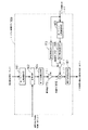
図1は、本発明の実施形態1に係る画像動き補正装置を示すブロック図である。
【0018】
同図において、光学的振れ補正系1は、撮像装置の揺れにより生じる画像の動きを光学的に補正するための手段であって、ここでは、一例として可変頂角プリズム(以下”VAP”と略記する)が適用される。なお、VAP1に関しては、例えば特開平2ー13901号に詳細が開示されているため、その詳細な説明は省略する。
【0019】
光学的振れ補正系駆動制御手段2は、VAP1を駆動および制御するための手段である。また、角度検出手段3は、VAP1の平行平面板の実際の回転角を検出して出力する手段であり、光学的振れ補正系駆動制御手段2と共にVAP1を駆動制御するための帰還制御ル−プを構成している。
【0020】
撮像光学系4は、光学的ズ−ム動作、合焦動作するレンズ系からなり、また、撮像光学系駆動制御手段5は、撮像光学系4を駆動制御して光学的ズ−ム動作、合焦動作を行わせる手段であって、撮像光学系4の焦点距離に関する情報を後述するシステム制御手段161に出力するようになっている。
【0021】
固体撮像素子6は、VAP1および撮像光学系4を介して入射する映像を電気信号に変換するものであり、この素子6は、固体撮像素子駆動制御手段17によって駆動および制御されるようになっている。
【0022】
アナログ信号処理手段7は、固体撮像素子6により得られた画像信号に対してガンマ補正等のアナログ信号処理を施すための手段である。A/D変換手段8は、アナログ信号をデジタル信号に変換するものであり、デジタル信号処理手段9は、A/D変換手段8によってデジタル信号に変換された画像信号に対してノイズ除去、輪郭強調等のデジタル信号処理を施すものである。
【0023】
A/D変換手段8によりデジタル信号に変換された画像信号は、同時に動き検出手段10にも送られ、ここでフィ−ルド間の画像の水平・垂直方向の位置ずれ量を示すベクトル(以下、これを検出ベクトルと称す)がフィ−ルド毎に検出される。
【0024】
センサ11は、撮像装置自体の動きを検出するためのものであって、この実施形態1では、一例として角速度を検出する角速度センサが適用される。
【0025】
角速度センサ11は、ヨ−およびピッチの2方向の動きを検出するために2個必要となるが、図には1方向分のみを示している。
【0026】
ゲイン調整手段12は、角速度センサ11の出力の信号レベルの調整を行うもので、たとえばアンプ回路からなる。HPF13は、角速度センサ11の出力に含まれるドリフト成分を除去するための高域通過フィルタ、LPF14は、角速度センサ11の出力に含まれるノイズ成分を除去するための低域通過フィルタであり、A/D変換手段15は、角速度センサ11の出力をデジタル信号に変換するための手段である。
【0027】
システム制御手段16aは、特許請求の範囲における合成手段に相当するもので、動き検出手段11、撮像光学系駆動制御手段5および角速度センサ11からそれぞれ得られた各情報に基づいて画像の動き補正のために必要な情報(以下、動き補正信号と称する)を算出し、これを光学的振れ補正系駆動制御手段2に送る。光学的振れ補正系駆動制御手段2は、その動き補正信号に基づいてVAP1を駆動制御する。
【0028】
図2は動き検出手段10の内部構成の一例を示すブロック図である。
【0029】
この動き検出手段10は、代表点記憶回路101、相関演算回路102、および動きベクトル検出回路103からなる。
【0030】
代表点記憶回路101は、A/D変換手段8を経て入力されてくる現フィールドの画像信号を複数の領域に分割し、各領域に含まれる特定の代表点に対応する画像信号を代表点信号として記憶するとともに、既に記憶されている現フィールドより1フィールド前の代表点信号を読み出して相関演算回路102に与えるようになっている。
【0031】
相関演算回路102は、前代表点信号と現フィールドの画像信号間の相関演算を行い、前代表点信号と現フィールドの画像信号の差を比較するものであって、その出力は動きベクトル検出回路103に与えられる。
【0032】
動きベクトル検出回路103は、相関演算回路102における演算結果から、前フィールドと現フィールドの間の画像の動きベクトル(検出ベクトル)を1画素単位で検出する。
【0033】
したがって、この構成においては、画像の1フィ−ルド前後間でのマッチングをとるために、検出ベクトルを得るために1フィ−ルド期間の時間遅れが生じることになる。
【0034】
図3はシステム制御手段16aの内部構成の一例を示すブロック図である。
【0035】
第1ゲイン/位相補償手段161は、動き検出手段10で得られる検出ベクトルに対して、そのゲインおよび位相を調整するものである。
【0036】
また、変換手段162は、第1ゲイン/位相補償手段161で調整された後の検出ベクトルを、撮像光学系駆動制御手段5から得られる撮像光学系4の焦点距離の情報に基づいて、単位時間当りの移動角度(角速度)に変換するものである。この場合の単位時間とは、例えば角速度センサ11の出力をサンプリングする際の1周期に設定することができる。
【0037】
第2ゲイン/位相補償手段163は、第1ゲイン位相補償手段161と同様に、A/D変換手段15を経て得られた角速度センサ11の検出出力に対してそのゲインおよび位相を調整する。
【0038】
第1帯域抽出手段164は、変換手段162を経て得られた角速度の信号の内、一部の帯域成分(ここでは動き補正に好適な低周波成分)のみを抽出する一種のフィルタである。また、第2帯域抽出手段165は、第2ゲイン/位相補償手段163を経て得られた角速度の信号の内、一部の帯域成分(ここでは動き補正に好適な高周波成分)のみを抽出する一種のフィルタである。そして、第1、第2帯域抽出手段164、165を通過した各信号は、加算器166によって加算される。
【0039】
補正信号発生手段167は、加算器165による加算結果を積分し、画面上に予め設定された基準位置からの変位角度(移動角)を求めて動き補正信号を発生するものである。
【0040】
次に、この実施形態1に係る画像動き補正装置の動作を説明する。なお、固体撮像素子7で得られる画像信号に基づく動き検出動作、角速度センサ11で検出される動き検出動作、およびVAP1の駆動制御等の一連の動作は、水平、垂直両方向に対してそれぞれ行われるが、水平、垂直両方向ともその内容は基本的に同じであるから、ここでは説明を簡略化するため、水平、垂直方向の別は区別せずに説明する。
【0041】
固体撮像素子6により得られた画像信号は、アナログ信号処理手段7を経て、A/D変換手段8でデジタル化された後、デジタル信号処理手段9および動き検出手段10にそれぞれ送られる。
【0042】
動き検出手段10では、1フィ−ルド前後間の画像の位置ずれ量(検出ベクトル)が検出され、その検出ベクトルがシステム制御手段16aに送られる。
【0043】
システム制御手段16aにおいては、まず、第1ゲイン/位相補償手段161によって検出ベクトルに対するゲインおよび位相が調整される。特に、動き検出手段10が検出ベクトルを得るまでに生じる1フィ−ルド期間の時間(位相)遅れが補償される。変換手段162は、画面上での画素単位で得られる検出ベクトルを、撮像光学系駆動制御手段5から得られる撮像光学系4の焦点距離の情報に基づいて単位時間当りの角速度に変換する。
【0044】
第1帯域抽出手段164は、変換手段162からの信号出力のうち、動き補正に好適な帯域成分として、低周波成分を抽出する。その理由は、画像信号に基づく動き検出においては、角速度センサ11の検出出力に基づく動き検出に比べて低周波帯域において一層正確な動き検出が可能となるためである。すなわち、画像信号に基づいて動きを検出する場合、画像のサンプリング周期によって動きを検出できる周波数が限定される。例えば、NTSC方式を対象とする場合には、サンプリング周波数は60Hzであることから、画像信号に基づいて動きを検出する場合には、サンプリング定理より動き検出の帯域は30Hz以下に限定される。
【0045】
これに対して、第2帯域抽出手段165は、第2ゲイン/位相補償手段163の出力のうち、動き補正に好適な帯域成分として高周波成分を抽出する。その理由は、角速度センサ11の検出出力に基づいて動きを検出する場合、センサ11出力に含まれるドリフト等の低域成分を除去する上でHPF13を設けているため、低周波の動きに対する検出精度が低下しているからである。
【0046】
第1,第2帯域抽出手段164,165の両出力は、加算器166で加算され、補正信号発生手段167において、動き補正信号が求められる。
【0047】
光学的振れ補正系駆動制御手段2は、動き補正信号に応じて、VAP1を駆動制御することで画像の動きを補正する。
【0048】
つまり、この実施形態1では、動き検出手段10によって得られた低周波帯域の動きの情報、および角速度センサ11から得られた高周波帯域の動きの情報の両者によってVAP1を制御するので、低周波域から高周波域までにわたる画像の動きを高精度に補正することが可能となる。
【0049】
また、第1、第2帯域抽出手段164,165は、図3に示したような加算器166の直前に設ける場合に限定されるものではなく、例えば、第1帯域抽出手段164は、第1ゲイン/位相補償手段161の前段、もしくはA/D変換手段8と動き検出手段10との間に、また、第2帯域抽出手段165は、A/D変換手段15とシステム制御手段16aとの間に、それぞれ設置する構成であってもよい。
【0050】
(実施形態2)
図4は、本発明の実施形態2に係る画像動き補正装置のシステム制御手段の構成を示すブロック図であり、上述の実施形態1に係る図3に対応する部分については同一の符号を付す。
【0051】
この実施形態2の特徴は、システム制御手段16bの構成にある。すなわち、このシステム制御手段16bは、図3に示した構成に対して、さらに第1、第2乗算器171,172、および振動帯域検出手段173が追加されている。
【0052】
第1、第2乗算器171,172は、それぞれ第1、第2帯域抽出手段164,165の各出力に対して、所定の重み付けの乗数α、1−α(ただし、0≦α≦1)を乗算するものである。また、振動帯域検出手段173は、例えば、高速フーリエ変換等の時系列信号の周波数分解を行う機能を有しており、A/D変換手段15を経て得られた角速度センサ11の出力に基づいて撮像装置の動きの主要な周波数帯域を検出し、その結果から第1、第2乗算器171,172で乗算すべき乗数α,1−αの値を決定するものである。
【0053】
その他の構成は、前述の実施形態1の図3に示した場合と同じであるから、ここでは詳しい説明は省略する。
【0054】
次に、この実施形態2に係る画像動き補正装置の動作について説明する。
【0055】
振動帯域検出手段173は、角速度センサ11によって検出された撮像装置の動きから、その主要な振動帯域を検出し、その結果に基づいて第1、第2乗算器171,172における乗数α,1−αを決定する。
【0056】
第1、第2乗算器171,172は、振動帯域検出手段173で決定された各々の乗数α,1−αを、第1、第2帯域抽出手段164,165の出力に対してそれぞれ乗算する。
【0057】
ここで、振動帯域検出手段173は、撮像装置の動きが画像データに基づく動き検出だけでは困難となる高周波成分(これは画像のサンプリング周波数で決まる)が支配的となる場合には、αを0に設定する。このため、第1乗算器171の出力が停止される。
【0058】
これに対して、振動帯域検出手段173は、撮像装置の動きが角速度センサ11では検出が困難となる低周波成分が支配的となる場合には、αを1に設定する。このため、第2乗算器172の出力が停止される。
【0059】
このように、撮影状態によって2系統ある動きを検出する手段のうち1系統の使用を停止することができるため、実施形態1の場合よりもより一層効果的に動きを検出することができる。
【0060】
また、高周波成分と低周波成分で際だった偏りがない場合は、高周波成分と低周波成分の比率に応じて、乗数αを0以上1以下の範囲で略連続的に変化させることもできる。
【0061】
たとえば、図5(a)に示すように、高周波成分と低周波成分の比率に応じてαの値を直線状に変化させたり、図5(b)に示すように高周波成分が幾分大きくなるまではα=1とし、高周波成分が一定値ρ1を越えたときには高周波成分と低周波成分の比率に応じてαの値を直線状に変化させ、さらに高周波成分が一定値ρ2を越えたときにはα=0に設定したり、図5(c)に示すように。高周波成分と低周波成分の比率に応じてαを連続的に曲線状に変化させたりすることができる。
【0062】
なお、この実施形態2における他の構成、動作、作用等は、前述の実施形態1と同様であるから、ここでは説明を省略する。
【0063】
このように、この実施形態2では、撮影状態に応じて2系統ある動きを検出する手段の重み付けを変化させることができるので、実施形態1の場合よりもより一層、低周波から高周波までの画像の動きを高精度に補正することが可能となる。
【0064】
なお、この実施形態2では、振動帯域検出手段173は、角速度センサ11の出力に基づいて撮像装置の動きの主要な周波数帯域を検出するようにしているが、本発明はこれに限定されるものではなく、例えば、振動帯域検出手段173は、動き検出手段10の出力に基づいて撮像装置の動きの主要な周波数帯域を検出する構成とすることも可能である。また、この振動帯域検出手段173は、例えば、高域通過フィルタおよび低域通過フィルタのようなフィルタ手段による構成とすることもできる。
【0065】
さらに、この実施形態2では、重み付けの乗数α,1−αを決定するのに、高周波成分と低周波成分との比を用いる場合について説明したが、これに限るものではなく、例えば、高周波成分と低周波成分の差によって乗数α,1−αを決定することもできる。
【0066】
(実施形態3)
図6は、本発明の実施形態3に係る画像動き補正装置のシステム制御手段163の構成を示すブロック図であり、上述の実施形態2に係る図4に対応する部分については同一の符号を付す。
【0067】
前述の実施形態2では、システム制御手段16bは振動帯域検出手段173を備えているが、この実施形態3のシステム制御手段16cでは、その振動帯域検出手段173に代えて、焦点距離検出手段183を設けている。
【0068】
すなわち、この焦点距離検出手段183は、撮像光学系駆動制御手段5から得られた撮像光学系4の焦点距離を検出し、その焦点距離の情報に基づいて乗算器181および182で乗算する重み付けのための乗数α,1−α(ただし、0≦α≦1)を決定するものである。
【0069】
その他の構成は、前述の実施形態2の場合と同じであるから、ここでは詳しい説明は省略する。
【0070】
次に、この実施形態3に係る画像動き補正装置の動作について説明する。
【0071】
一般に、撮像装置においては、撮像光学系4の焦点距離が長いほど撮影画角は狭く、逆に、焦点距離が短いほど撮影画角は広くなる。このため、同じ角度だけ撮像装置が動いたとしても、画面上に現れる動き量は焦点距離によって変化する。すなわち、同じ角度だけ撮像装置が動いた場合でも、焦点距離が長いほど画面に現れる動きは大きくなり、逆に、焦点距離が短いほど画面に現れる動きは小さくなる。
【0072】
また、撮像装置の動きの原因である手ぶれは、先に掲げた文献(”ビデオカメラの画振れ防止技術の開発”テレビジョン学会技術報告Vol.11,No.28,pp19〜24(1987))にも明記されているように、単位時間についてみると、周波数の低い成分ほど動きの変移量が大きく、周波数の高い成分ほど動きの変移量が小さいことが知られている。
【0073】
このことから、撮像光学系の焦点距離が短い場合、撮像画像に現れる動きは低周波成分が支配的となる。また、焦点距離が長い場合は、画像の動きは低周波成分、高周波成分共に大きく画像の動きとして現れるが、実際には、補正画角には限界があり、焦点距離が長い場合には画像の動きが顕著になり過ぎて低周波成分の補正が困難になる。
【0074】
よって、焦点距離検出手段183は、撮像光学系の焦点距離が短い場合は、撮像画像に現れる動きは低周波成分が支配的となるため、動き検出手段10による動き検出だけで十分に動き補正が可能であり、このため、αを1に設定する。これにより、第2乗算器172の出力が停止される。一方、撮像光学系の焦点距離が長い場合は、動き検出手段10による動き検出では動きの補正が困難であり、高周波成分が支配的となるため、角速度センサ11による動き検出のみで動き補正が行えるように、αを0に設定する。これにより、第1乗算器171の出力が停止される。
【0075】
このように、撮影状態によっては、2系統ある動きを検出する手段のうち1系統の使用を停止できるため、消費電力の低減が可能となる。
【0076】
また、焦点距離が中間程度に設定されている場合は、焦点距離に応じてαを0以上1以下の範囲で略連続的に変更することができる。その場合のαの設定の仕方としては、実施形態2の場合と同様に、前述の図5に示したような方法を採用することができる。
【0077】
なお、本実施の形態における他の構成、動作、作用等は前述の実施形態1,2と同様であるから、ここでは説明は省略する。
【0078】
以上のように、本発明の実施形態3では、低周波から高周波までの画像の動きを高精度に補正できると共に、撮影状態に応じて2系統ある動きを検出する手段のうち1系統の使用を停止でき、これより消費電力の低減が可能となる。
【0079】
なお、前述の実施形態2,3では、いずれも重み付けのための乗数αを自動的に変化させる構成を示したが、例えば、撮影者の意思によって乗数αを0または1に設定できるスイッチ手段を設ければ、撮影者の判断によって2系統ある動きを検出する手段のうち1系統の使用を停止することができ、これよっても消費電力の低減が可能な構成が実現できることは明らかである。
【0080】
なお、実施形態2で説明した振動帯域検出手段173および実施形態3で説明した焦点距離検出手段183によるα値設定の両者を組み合わせた構成も考えられる。その場合、乗数αの値をより一層精度よく設定でき、撮影状況に応じた操作性の向上が図れる。
【0081】
(実施形態4)
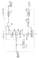
図7は、本発明の実施形態4に係る画像動き補正装置の全体構成を示すブロック図、図8は同装置のシステム制御手段の構成を示すブロック図であり、実施形態1に係る図1ないし図3に対応する部分については同一の符号を付す。
【0082】
動き検出手段10の出力、つまり固体撮像素子6で撮像された画像に含まれる動きは、VAP1だけでは補正しきれなかった残留動きに相当する。
【0083】
そこで、この実施形態4では、その残留動きを除去するために、実施形態1の場合と比較すると、画像メモリ19、画像メモリ駆動制御手段20、および電子ズーム手段21が設けられており、また、システム制御手段16dとして、動き検出手段10の出力を積分する積分手段221が追加されている。
【0084】
上記の画像メモリ19は、デジタル信号処理手段9を経た画像信号を一旦記憶するもので、たとえば、RAM等で構成される。
【0085】
画像メモリ駆動制御手段20は、画像メモリ19に対する画像信号の書き込み、読み出しを制御し、かつ、画像メモリ19に記憶されていた画像信号の一部を読み出した場合には、画像を所望の大きさに拡大するよう指令を後述する電子ズーム手段21に送るものである。
【0086】
電子ズーム手段21は、画像メモリ19から読み出された一部の画像信号に対し電子的な拡大処理(電子ズーム処理)を施し、画像を拡大するものである。
【0087】
また、システム制御手段164を構成する積分手段221は、動き検出手段10の出力を積分するものである。
【0088】
その他の構成は、実施形態1の場合と同様であるから、ここでは詳しい説明は省略する。
【0089】
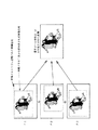
図9は、画像メモリ19からの画像の読み出し制御と、電子ズーム手段21による画像の拡大処理による動き補正の原理を説明する模式図である。
【0090】
同図において、F1,F2,F3は画像メモリ19に記憶される連続する3つのフィールド画像であり、これより動きに応じてその画像の一部(破線で囲まれた内側の領域)を切り出すことで画像の動きを補正することができ、かつ、その切り出した画像の一部を電子ズーム手段21によって拡大処理を行う。
【0091】
画像の切り出し部分以外の部分(破線で囲まれた領域の外側の領域)は動き補正のためのマージンにあたる部分であり、このマージンを広く取れば取るほど(換言すれば、画像の切り出し部分を小さく設定するほど)、画像メモリ19からの画像の読み出し制御によって動き補正を行える可能範囲は広がるが、その反面、電子ズーム手段21による拡大倍率が増し、出力画像の解像度に劣化が生じる。
【0092】
次に、この実施形態4に係る画像動き補正装置の動作について説明する。
【0093】
前述のように、動き検出手段10の出力は、VAP1だけでは補正しきれなかった残留動きに相当する。
【0094】
画像メモリ19には、動き検出手段10により画像の動き検出がなされる間に、1フィールド分の画像が記憶される。そして、動き検出手段10により検出された画像の残留動きは、積分手段221によって積分され、画面の基準位置からの変位量が求められ、その変位量の情報が画像メモリ駆動制御手段20に送られる。画像メモリ駆動制御手段20は、この変移量の情報に基づいて、画像メモリ19からの画像の読み出し位置を制御する。
【0095】
これにより、VAP1だけでは補正しきれなかった残留動きが有効に除去され、その後、電子ズーム手段21によって画像が所望の大きさに拡大される。
【0096】
なお、その他の動作、作用等は実施形態1と同様であるから、ここでは説明は省略する。
【0097】
このように、この実施形態4では、実施形態1の場合よりも更に画像の動きを高精度に補正することが可能となる。
【0098】
なお、この実施形態4では、画像メモリ19から読み出した画像信号に対して、電子ズーム手段21により拡大処理を施す場合について説明したが、本発明は、これに限るものではなく、例えば、標準の固体撮像素子6よりも画素数の多い固体撮像素子を用い、最終出力として必要な画素数以上の画像を撮像し、これを画像メモリ19に記憶し、画像メモリ19からは最終出力に必要な画素数分だけ画像を読み出す構成も考えられる。その場合、電子的に画像を拡大する必要が無いため、高画質な出力画像を得ることができる。その場合に1画素1ライン以下の動き補正を行うためには、電子ズーム手段21によってズーム倍率が1倍のズーム処理(単なる補間処理)を施せばよいことは明らかである。
【0099】
また、この実施形態4の構成に対して、実施形態2,3の構成を組み合わせることも可能である。
【0100】
(実施形態5)
この実施形態5の特徴は、実施形態4に係る図7および図8の構成に対して、さらに電子ズーム操作手段23(図7参照)を設けたことである。
【0101】
この電子ズーム操作手段23は、撮影者が電子的拡大処理(電子ズーム処理)の有無(ON/OFF)、および電子ズーム処理を行う場合のズーム倍率を操作するものであって、例えば、レバー状の指示装置(ズームレバー)、ボタンスイッチ、ダイヤル状の指示装置等で実現できるが、これに限るものではない。
【0102】
その他の構成は、実施形態4の場合と同様であるから、ここでは詳しい説明は省略する。
【0103】
この実施形態5において、画像メモリ駆動制御手段20は、電子ズーム操作手段23からの指令により、電子ズーム処理が行われる場合(電子ズームON時)には、積分手段221で得られる画像の変移量とズーム倍率とに基づいて、画像メモリ19からの画像の読み出し位置を制御するとともに、電子ズーム手段21による画像の拡大を行う。
【0104】
一方、画像メモリ駆動制御手段20は、電子ズーム処理を行わない場合(電子ズームOFF時)には、画像メモリ19からの画像の読み出し位置制御および電子ズーム手段21による画像の拡大を停止する。
【0105】
このように、電子ズームOFF時は、動き補正は、VAP1の駆動制御のみによるため、撮影者の動き補正による解像度の劣化を認識させることなく、出力画像の解像度の劣化が無い高精度な動き補正が行われる。また、電子ズームON時は、VAP1による補正に加えて、画像メモリ19からの画像の切り出しによる動き補正が行われる。
【0106】
なお、この実施形態5におけるその他の動作、作用等は実施形態4と同様であるため説明は省略する。
【0107】
また、この実施形態5で、固体撮像素子6は標準の画素数の固体撮像素子でも、標準より画素数の多い固体撮像素子でも同様の効果が得られることは言うまでもない。さらに、この実施形態5に、上記の実施形態2,3の構成を組み合わせることも可能である。
【0108】
(実施形態6)
図10は、本発明の実施形態6に係る画像動き補正装置の全体構成を示すブロック図、図11は同装置のシステム制御手段の構成を示すブロック図であり、上述の実施形態1に係る図1ないし図3に対応する部分については同一の符号を付す。
【0109】
この実施形態6の特徴は、実施形態1に係る図1の構成に対して、さらに光学ズーム操作手段24を設け、また、システム制御手段16eとしては、図3に示した構成に対して、さらに、スイッチ251とスイッチ制御手段252とが追加されていることである。
【0110】
光学ズーム操作手段24は、撮影者が撮像光学系4の焦点距離を手動で操作するものであり、この手段24からの指令により、撮像光学系駆動制御手段5は、撮像光学系の焦点距離を変化させて光学的なズームを行うようになっている。
【0111】
また、上記のスイッチ251は、第1帯域抽出手段164の出力をON/OFFするものであり、スイッチ制御手段252は、撮像光学系駆動制御手段5から得られた撮像光学系4の焦点距離の変化を検出し、それに基づいてスイッチ251をON/OFF制御するものである。
【0112】
その他の構成は、図1ないし図3に示した実施形態1の場合と同じであるから、ここでは詳しい説明は省略する。
【0113】
次に、この実施形態6に係る画像動き補正装置の動作について説明する。
【0114】
焦点距離を変化させる光学ズーム中においては、撮像画像は中心から放射状に動く。このため、動き検出手段10では、フィールド間の画像の動きが検出範囲内で一様にならないため、動きを検出する精度が低下する。これに対して、角速度センサ11は、光学ズーム中であっも、撮像装置自体の動きを検出する精度が低下することはない。
【0115】
実施形態1のように、光学ズーム中であるか否かに関係なく、常に動き検出手段10による動き検出と、角速度センサ11による動き検出との両結果に基づいて動き補正を行う場合には、光学ズーム中に動き検出手段10の検出精度が低下して誤動作の原因となり得る。
【0116】
そこで、この実施形態6においては、撮像光学系駆動制御手段5から得られた撮像光学系4の焦点距離の変化を検出し、焦点距離に変化が有る場合(つまり、光学ズーム中)は、スイッチ制御手段252がスイッチ251をOFFにし、動き検出手段10による動き検出結果を動き補正に使用しないようにしている。
【0117】
これにより、光学ズーム中でも誤動作が無く、高精度に動き補正可能な撮像装置を実現することができる。
【0118】
なお、この実施形態6における他の動作、作用等は実施形態1と同様であるため、ここでは説明を省略する。
【0119】
また、光学ズーム中は、スイッチ251を単純にOFFにするのではなく、スイッチ251によって動き検出手段10から第1帯域抽出手段164までの処理全体を停止するようにして、消費電力の低減を図ることも可能である。
【0120】
また、実施形態2,3で示したような第1、第2乗算器171,172を設け、光学ズーム中は、第1乗算器171の乗数αを0にしても、この実施形態6と同じ効果を実現することができる。
【0121】
また、この実施形態6の構成に対して、上記の実施形態2,3で説明したように、振動帯域検出手段173と焦点距離検出手段183の一方または両方、および2つの乗算器171,172を設けることも可能である。
【0122】
(実施形態7)
図12は本発明の実施形態7に係る画像動き補正装置の全体構成を示すブロック図、図13は同装置のシステム制御手段の構成を示すブロック図であり、上述の実施形態4に係る図7および図8に対応する部分について同一の符号を付す。
【0123】
この実施形態7の特徴は、実施形態4に係る図7の構成に対して、さらに光学ズーム操作手段24を設け、また、システム制御手段16fとしては、図8に示した構成に対して、さらに、2つのスイッチ251,261、およびスイッチ制御手段252が追加されていることである。
【0124】
この実施形態7の備える光学ズーム操作手段24、一方側のスイッチ251、およびスイッチ制御手段252は、上記の実施形態6で説明した構成に対応している。
【0125】
また、他方のスイッチ261は、動き検出手段10から積分手段221に入力される信号をON/OFFするものであり、両スイッチ251,261が共にスイッチ制御手段252の検出出力に基づいてON/OFF制御されるようになっている。
【0126】
その他の構成は、図7および図8に示した実施形態4の場合と同じであるから、ここでは詳しい説明は省略する。
【0127】
次に、この実施形態7の画像動き補正装置の動作について説明する。
【0128】
実施形態6において、焦点距離を変化させる光学ズーム中は、動き検出手段10による動き検出精度が低下し、誤動作の原因になり得ることを説明したが、このことは、実施形態4の構成においてもそのまま当てはまる。
【0129】
そこで、この実施形態7では、実施形態6と同様に、光学ズーム中は一方のスイッチ251と共にスイッチ261も同時にOFFとすることで、画像の動き検出に基づく動き補正を停止するとともに、画像メモリ19からの画像の切り出し位置の調整による動き補正も同時に停止させるようにしている。
【0130】
このようにすれば、光学ズーム中でも誤動作が無く、高精度に動き補正が可能な撮像装置を実現することができる。
【0131】
なお、本実施の形態における他の構成、動作、作用等は実施の形態4および実施の形態6と同様であるため説明は省略する。
【0132】
また、光学ズーム中は、スイッチ261を単純にOFFにするのではなく、動き検出手段10による処理や積分手段221による処理、さらには画像メモリ駆動制御手段20を同時に停止させて消費電力の低減を図ることも可能である。
【0133】
また、この実施形態7の構成に対して、上記の実施形態2,3で説明したように、振動帯域検出手段173と焦点距離検出手段183の一方または両方、および2つの乗算器171,172を設けることも可能である。
【0134】
なお、上記の各実施形態1〜7の説明においては、撮像装置の表示方式については、特に言及しなかったが、本発明は、NTSC、PAL、SECAM等のいかなる表示方式を採用した撮像装置においても適用可能である。また、撮像装置の固体撮像素子6の素子数に関しても、特に言及しなかったが、単板式撮像装置、2板式撮像装置、3板式撮像装置のいずれの撮像装置においても、本発明が有効である。また、固体撮像素子ではなく撮像管を用いた撮像装置においても同様に本発明が有効である。
【0135】
その他の変形例
上記の各実施形態1〜7に対して、次のような構成の変更を加えることが可能である。
【0136】
(1) 上記の各実施形態1〜7において、光学的振れ補正系1は、可変頂角プリズム(VAP)として説明を行ったが、これに限るものではなく、撮像光学系4に対して相対的に駆動されることにより光軸補正を実現する手段、例えば、複数のレンズからなりそのレンズの一部または全てを光軸に直交する方向にシフトさせることで光軸を移動させる手段(例えば、特願昭63−201622号に開示されている手段)であっても、光学的振れ補正系1として使用することができる。
【0137】
また、光学的振れ補正系1として、撮像光学系4および固体撮像素子6等を撮像装置の筺体に対して回動自在に支持および駆動することで、動きを補正する構成(例えば、”ビデオカメラの画振れ防止技術の開発”テレビジョン学会技術報告Vol.11,No.28,pp19〜24(1987)参照))を採用することも可能である。
【0138】
(2) 上記の各実施形態1〜7において、動き検出手段10による動き検出は、毎フィールド行うものとして説明したが、これに限るものではなく、例えば、2フィールドに一度ずつ動き検出を行い、動き検出を行わないフィールドでは、前フィールドまでに得られた動き検出結果を基に、画像の動きを予測し、画像の動き補正を行うような構成も考えられる。さらに、フレーム毎に動き検出を行う構成も考えられる。
【0139】
(3) 各システム制御手段16a〜16fは、電子回路、もしくはマイクロコンピュ−タ上でのソフトウエア処理により実現することが可能であることは言うまでもない。
【0140】
(4) システム制御手段16a〜16fを構成する変換手段162において、検出ベクトルを移動角度(角速度)に変換する場合に、撮像光学系駆動制御手段5により得られる撮像光学系4の焦点距離に関する情報を用いることとしたが、これに限るものではなく、例えば、赤外線等を用いた測距手段によって撮像装置と被写体との距離を測定し、この距離情報を上記焦点距離情報の代わりに用いることも可能である。
【0141】
【発明の効果】
本発明によれば、撮像装置自体の動きを検出する手段と、画像信号から画像の動きを検出する手段とを備え、これら2つの検出手段から得られた情報の双方に基づきいて画像の振れを補正するようにしているので、焦点距離に拘わらず一定の補正画角を確保することができ、かつ、高精度な動き補正を実現できる画像動き補正装置を実現することができる。これに加えて、画像動き補正装置の低消費電力化も可能であるという効果を奏する。
【図面の簡単な説明】
【図1】本発明の実施形態1に係る画像動き補正装置の全体を示すブロック図である。
【図2】同装置を構成する動き検出手段を示すブロック図である。
【図3】同装置を構成するシステム制御手段を示すブロック図である。
【図4】本発明の実施形態2に係る画像動き補正装置を構成するシステム制御手段を示すブロック図である。
【図5】本発明の実施形態2による重み付けのための乗数αの値を決定する一方法を説明するグラフである。
【図6】本発明の実施形態3に係る画像動き補正装置を構成するシステム制御手段を示すブロック図である。
【図7】本発明の実施形態4に係る画像動き補正装置の全体を示すブロック図である。
【図8】同装置を構成するシステム制御手段を示すブロック図である。
【図9】本発明の実施形態4に係る画像の拡大処理のよる動き補正の原理を説明するための図である。
【図10】本発明の実施形態6に係る画像動き補正装置の全体を示すブロック図である。
【図11】同装置を構成するシステム制御手段を示すブロック図である。
【図12】本発明の実施形態7に係る画像動き補正装置の全体を示すブロック図である。
【図13】同装置を構成するシステム制御手段を示すブロック図である。
【符号の説明】
1…光学的振れ補正系
2…光学的振れ補正系駆動制御手段
3…角度検出手段
4…撮像光学系
5…撮像光学系駆動制御手段
6…固体撮像素子
7…アナログ信号処理手段
8…A/D変換手段
9…デジタル信号処理手段
10…動き検出手段
11…角速度センサ
12…アンプ
13…HPF
14…LPF
15…A/D変換手段
16a〜16f…システム制御手段(合成手段)[0001]
TECHNICAL FIELD OF THE INVENTION
The present invention relates to an image motion correction device used for camera shake correction of an imaging device.
[0002]
[Prior art]
For example, the following devices (1) to (3) have been proposed as image motion correcting devices for imaging devices.
[0003]
{Circle around (1)} A method in which an image pickup unit having an image pickup optical system and a solid-state image pickup device is supported by a gimbal mechanism, and drive control is performed based on movement information of the image pickup apparatus itself obtained from an angular velocity sensor, thereby correcting image movement. (For example, see "Development of Image Shake Prevention Technology for Video Cameras," Technical Report of the Institute of Television Engineers of Japan, Vol. 11, No. 28, pp. 19-24 (1987)).
[0004]
{Circle around (2)} A method of correcting a motion of an image by providing a variable apex angle prism in front of an imaging optical system and driving and controlling the same based on information from an angular velocity sensor (for example, an “optical image stabilization system” TV) See John Technical Report Vol. 17, No. 5, pp. 15-20 (1993)).
[0005]
{Circle around (3)} A method of detecting the presence or absence of image movement from an image signal obtained by capturing an image of a subject, and clipping a part of the original image based on the detection result to correct the image movement (for example, “” Pure electronic image stabilization system, "Technical Report of the Institute of Television Engineers of Japan, Vol. 15, No. 7, pp. 43-48 (1991)").
[0006]
[Problems to be solved by the invention]
The above methods (1) and (2) optically correct the motion of an image based on information from the angular velocity sensor, but in such a method, the output drift due to the sensitivity and temperature characteristics of the angular velocity sensor Due to such problems as above, it is difficult to realize highly accurate motion correction.
[0007]
In the method of (3), since all of the motion compensation is performed by signal processing, high-precision motion compensation can be realized, but on the other hand, the larger the focal length of the photographing lens, the more the motion compensation is possible. The angle of view becomes smaller.
[0008]
The present invention solves the above-described conventional problems, and can always secure a fixed angle of view that enables motion correction without being affected by the focal length, and can realize highly accurate motion correction. It is an object to provide an image motion correction device.
[0009]
[Means for Solving the Problems]
In order to solve this problem, the present invention provides a solid-state imaging device, an imaging optical system for forming a subject image on the solid-state imaging device, and an optical shake correction system for optically correcting the movement of a captured image. The following configuration is employed in an image motion compensating apparatus including an image pickup system composed of: and an optical shake correction system drive control unit that drives and controls the optical shake correction system.
[0010]
In the invention according to
[0011]
In the invention according to
[0012]
In this case, as the synthesizing process by the signal synthesizing means, both signals weighted by predetermined multipliers α and 1−α can be added. The multiplier α can also be determined based on information on one or both of the vibration frequency band of the imaging apparatus itself and the focal length of the imaging optical system. This makes it possible to realize high-precision motion correction while securing a fixed correction angle of view regardless of the focal length. Further, the multiplier α can be determined according to the ratio between the high frequency band component and the low frequency band component of the vibration of the imaging device itself, or the difference between the two components. Furthermore, the frequency band component of the vibration of the imaging device itself can be extracted from the output of the sensor or the output of the motion detecting means.
[0013]
Claim5In the invention according to the description, the claims3 or Claim 4The image motion compensating device according toThe frequency band component of the vibration of the imaging device itself can be extracted from the output of the sensor or the output of the motion detecting means.
[0014]
Claim6In the invention according to the description, the claims1StatedIn addition to the configuration, a storage unit for storing an image signal obtained from the imaging system, and a storage unit driving control unit for controlling the reading of the image signal by driving the storage unit are provided, and output from the combining unit. The optical shake correction system is driven and controlled by a drive signal, and the storage unit drive control unit is configured to output an image signal from the storage unit by another drive signal calculated based on a motion detection result by the motion detection unit. The readout of images to correct image movementThings. Thereby, high-precision motion correction can be realized while securing a fixed correction angle of view and without recognizing the deterioration of resolution due to the motion correction of the photographer, regardless of the focal length.
[0015]
Claim7In the invention according to the descriptionAn electronic zooming means for performing an electronic enlarging process on the image signal read from the storage means, in addition to the configuration according to claim 6, wherein the optical signal is outputted by the synthesizing means. The drive control unit controls the shake correction system, and the storage unit drive control unit calculates the value based on the motion detection result by the motion detection unit only when executing the electronic enlargement process in accordance with a command from the electronic zoom unit. The reading of the image signal from the storage means is controlled by the other drive signal to correct the motion of the image. Thereby, high-precision motion correction can be realized while securing a fixed correction angle of view and without recognizing the deterioration of resolution due to the motion correction of the photographer, regardless of the focal length.
[0016]
In the invention according to
The signal synthesizing unit includes a unit that stops outputting a drive signal obtained based on a detection result of the motion detection unit during a period in which the focal length is changed by the imaging optical system, and the focus is controlled by the imaging optical system. During the period in which the distance is changing, only the drive signal formed from the information on the movement of the imaging device itself detected by the sensor, and in the period in which the focal length is fixed, the sensor and the movement detection are performed. Each of the optical shake correction systems is driven by a drive signal formed by synthesizing both signals of the motion detection result by the means.This is to control the movement of the image by controlling. Accordingly, it is possible to realize high-precision motion correction while ensuring a fixed correction angle of view regardless of the focal length, and without malfunction even while the focal length is changing.
[0017]
BEST MODE FOR CARRYING OUT THE INVENTION
(Embodiment 1)
FIG. 1 is a block diagram illustrating an image motion correction device according to
[0018]
In FIG. 1, an optical
[0019]
The optical shake correction system
[0020]
The imaging optical system 4 includes a lens system that performs an optical zoom operation and a focusing operation, and an imaging optical system
[0021]
The solid-state imaging device 6 converts an image incident through the
[0022]
The analog
[0023]
The image signal converted into a digital signal by the A /
[0024]
The
[0025]
Although two
[0026]
The gain adjusting means 12 adjusts the signal level of the output of the
[0027]
The system control means 16a corresponds to the synthesizing means in the claims, and performs the motion correction of the image based on the information obtained from the motion detection means 11, the imaging optical system drive control means 5 and the
[0028]
FIG. 2 is a block diagram showing an example of the internal configuration of the motion detection means 10.
[0029]
The motion detection means 10 includes a representative
[0030]
The representative
[0031]
The
[0032]
The motion
[0033]
Accordingly, in this configuration, a time delay of one field period occurs in order to obtain a detection vector in order to perform matching before and after one field of the image.
[0034]
FIG. 3 is a block diagram showing an example of the internal configuration of the system control means 16a.
[0035]
The first gain /
[0036]
The
[0037]
The second gain /
[0038]
The first
[0039]
The correction signal generation means 167 integrates the result of addition by the
[0040]
Next, the operation of the image motion correction device according to the first embodiment will be described. A series of operations such as a motion detection operation based on an image signal obtained by the solid-
[0041]
The image signal obtained by the solid-state imaging device 6 is passed through an analog
[0042]
The motion detecting means 10 detects the amount of displacement (detection vector) of the image before and after one field, and sends the detected vector to the system control means 16a.
[0043]
In the
[0044]
The first
[0045]
On the other hand, the second
[0046]
Both outputs of the first and second band extracting means 164 and 165 are added by an
[0047]
The optical shake correction system drive control means 2 corrects the motion of the image by controlling the drive of the
[0048]
That is, in the first embodiment, since the VAP1 is controlled by both the information on the movement in the low frequency band obtained by the
[0049]
Further, the first and second band extracting means 164 and 165 are not limited to the case provided immediately before the
[0050]
(Embodiment 2)
FIG. 4 is a block diagram illustrating a configuration of a system control unit of the image motion compensating apparatus according to the second embodiment of the present invention, and the same reference numerals are given to parts corresponding to FIG. 3 according to the first embodiment.
[0051]
The feature of the second embodiment resides in the configuration of the system control means 16b. That is, the system control unit 16b has a configuration in which first and second multipliers 171 and 172 and a vibration
[0052]
The first and second multipliers 171 and 172 apply multipliers α and 1−α of a predetermined weight to the respective outputs of the first and second band extracting means 164 and 165 (where 0 ≦ α ≦ 1). Is multiplied by Further, the vibration
[0053]
The other configuration is the same as that shown in FIG. 3 of the first embodiment, and a detailed description is omitted here.
[0054]
Next, the operation of the image motion correction device according to the second embodiment will be described.
[0055]
The vibration band detecting means 173 detects the main vibration band from the movement of the imaging device detected by the
[0056]
The first and second multipliers 171 and 172 multiply the outputs of the first and second band extracting means 164 and 165 by the multipliers α and 1-α determined by the vibration band detecting means 173, respectively. .
[0057]
Here, the vibration band detecting means 173 sets α to 0 when the high frequency component (which is determined by the sampling frequency of the image) which makes the motion of the imaging device difficult only by the motion detection based on the image data becomes dominant. Set to. Therefore, the output of the first multiplier 171 is stopped.
[0058]
On the other hand, the vibration band detecting means 173 sets α to 1 when the movement of the imaging device is dominated by low frequency components that are difficult to detect by the
[0059]
As described above, it is possible to stop using one of the two systems of motion detecting means depending on the shooting state, so that the motion can be detected more effectively than in the first embodiment.
[0060]
Further, when there is no noticeable deviation between the high frequency component and the low frequency component, the multiplier α can be changed substantially continuously in the range of 0 or more and 1 or less according to the ratio of the high frequency component and the low frequency component.
[0061]
For example, as shown in FIG. 5A, the value of α is changed linearly according to the ratio between the high-frequency component and the low-frequency component, or the high-frequency component becomes somewhat large as shown in FIG. 5B. Up to α = 1, and the high-frequency component has a constant value ρ1Is exceeded, the value of α is changed linearly according to the ratio of the high-frequency component to the low-frequency component, and the high-frequency component is further changed to a constant value ρ2Is exceeded, α is set to 0, or as shown in FIG. Α can be continuously changed in a curved shape in accordance with the ratio between the high frequency component and the low frequency component.
[0062]
The other configuration, operation, operation, and the like in the second embodiment are the same as those in the first embodiment, and thus description thereof will be omitted.
[0063]
As described above, according to the second embodiment, the weighting of the means for detecting the movement of the two systems can be changed in accordance with the photographing state, so that the image from low frequency to high frequency can be further enhanced as compared with the first embodiment. Can be corrected with high accuracy.
[0064]
In the second embodiment, the vibration
[0065]
Further, in the second embodiment, the case has been described where the ratio between the high frequency component and the low frequency component is used to determine the weighting multipliers α, 1−α. However, the present invention is not limited to this. The multiplier α, 1−α can also be determined based on the difference between the low frequency component and the low frequency component.
[0066]
(Embodiment 3)
FIG. 6 shows a system control unit 16 of the image motion compensating apparatus according to the third embodiment of the present invention.35 is a block diagram showing the configuration of the second embodiment, and portions corresponding to FIG. 4 according to the second embodiment are denoted by the same reference numerals.
[0067]
In the above-described second embodiment, the system control unit 16b includes the vibration
[0068]
That is, the focal
[0069]
The other configuration is the same as that of the above-described second embodiment, and the detailed description is omitted here.
[0070]
Next, the operation of the image motion correction device according to the third embodiment will be described.
[0071]
In general, in the imaging apparatus, the angle of view is narrower as the focal length of the imaging optical system 4 is longer, and conversely, the angle of view is wider as the focal length is shorter. For this reason, even if the imaging device moves by the same angle, the amount of movement appearing on the screen changes depending on the focal length. That is, even when the imaging device moves by the same angle, the motion that appears on the screen increases as the focal length increases, and conversely, the motion that appears on the screen decreases as the focal length decreases.
[0072]
In addition, the camera shake which causes the movement of the imaging apparatus is described in the above-mentioned literature (“Development of Image Shake Prevention Technology for Video Cameras” Technical Report of the Institute of Television Engineers of Japan, Vol. It is known that, when it comes to the unit time, the lower the frequency component, the larger the amount of movement change, and the higher the frequency component, the smaller the amount of movement change.
[0073]
For this reason, when the focal length of the imaging optical system is short, the motion appearing in the captured image is dominated by low frequency components. Also, when the focal length is long, the motion of the image appears largely as the motion of the image in both the low-frequency component and the high-frequency component. However, there is actually a limit to the corrected angle of view. The motion becomes so remarkable that it becomes difficult to correct low frequency components.
[0074]
Therefore, when the focal length of the imaging optical system is short, the low-frequency component is dominant in the motion appearing in the captured image, and the motion correction can be sufficiently performed only by the motion detection by the
[0075]
As described above, depending on the shooting state, the use of one of the two systems for detecting the movement can be stopped, so that the power consumption can be reduced.
[0076]
When the focal length is set to an intermediate level, α can be changed substantially continuously within a range of 0 or more and 1 or less according to the focal length. In this case, as the method of setting α, the method shown in FIG. 5 can be employed as in the case of the second embodiment.
[0077]
Note that other configurations, operations, operations, and the like in the present embodiment are the same as those in the first and second embodiments, and thus description thereof will be omitted.
[0078]
As described above, according to the third embodiment of the present invention, the motion of the image from low frequency to high frequency can be corrected with high accuracy, and one of the means for detecting the motion of the two systems according to the shooting state is used. It can be stopped, thereby reducing power consumption.
[0079]
In the above-described second and third embodiments, the configuration in which the multiplier α for weighting is automatically changed has been described. However, for example, switch means that can set the multiplier α to 0 or 1 depending on the photographer's intention is provided. If provided, it is possible to stop the use of one of the two means of detecting movement based on the judgment of the photographer, and it is clear that a configuration capable of reducing power consumption can be realized.
[0080]
Note that a configuration in which both the vibration
[0081]
(Embodiment 4)
FIG. 7 is a block diagram illustrating an overall configuration of an image motion compensating apparatus according to Embodiment 4 of the present invention, and FIG. 8 is a block diagram illustrating a configuration of a system control unit of the image motion compensating apparatus. Parts corresponding to FIG. 3 are denoted by the same reference numerals.
[0082]
The output of the motion detecting means 10, that is, the motion included in the image captured by the solid-state imaging device 6 corresponds to a residual motion that cannot be completely corrected only by the VAP1.
[0083]
Therefore, in the fourth embodiment, an
[0084]
The
[0085]
The image memory drive control means 20 controls writing and reading of the image signal to and from the
[0086]
The electronic zoom means 21 performs electronic enlargement processing (electronic zoom processing) on a part of the image signals read from the
[0087]
Also, the system control means 164Is an integration means for integrating the output of the motion detection means 10.
[0088]
The other configuration is the same as that of the first embodiment, and the detailed description is omitted here.
[0089]
FIG. 9 is a schematic diagram for explaining the principle of the control of reading the image from the
[0090]
In the figure, F1, F2, and F3 are three consecutive field images stored in the
[0091]
The portion other than the cutout portion of the image (the region outside the region surrounded by the broken line) is a portion corresponding to a margin for motion compensation, and the wider this margin is, the smaller the cutout portion of the image is. The greater the setting, the greater the range in which motion correction can be performed by controlling the reading of the image from the
[0092]
Next, the operation of the image motion correction device according to the fourth embodiment will be described.
[0093]
As described above, the output of the motion detection means 10 corresponds to a residual motion that could not be completely corrected by VAP1 alone.
[0094]
The
[0095]
As a result, the residual motion that cannot be completely corrected by only the VAP1 is effectively removed, and thereafter, the image is enlarged to a desired size by the
[0096]
Note that other operations, operations, and the like are the same as those in the first embodiment, and a description thereof will not be repeated.
[0097]
As described above, in the fourth embodiment, the motion of the image can be corrected with higher accuracy than in the first embodiment.
[0098]
In the fourth embodiment, a case has been described in which the image signal read from the
[0099]
Further, it is possible to combine the configurations of the second and third embodiments with the configuration of the fourth embodiment.
[0100]
(Embodiment 5)
The feature of the fifth embodiment is that an electronic zoom operation means 23 (see FIG. 7) is further provided in the configuration of FIGS. 7 and 8 according to the fourth embodiment.
[0101]
The electronic zoom operation means 23 is used by the photographer to control the presence / absence (ON / OFF) of electronic enlargement processing (electronic zoom processing) and the zoom magnification when performing the electronic zoom processing. However, the present invention can be realized by an indicating device (zoom lever), a button switch, a dial-shaped indicating device, or the like, but is not limited thereto.
[0102]
The other configuration is the same as that of the fourth embodiment, and the detailed description is omitted here.
[0103]
In the fifth embodiment, when the electronic zoom processing is performed (when the electronic zoom is ON) in accordance with a command from the electronic zoom operation means 23, the image memory drive control means 20 controls the amount of displacement of the image obtained by the integration means 221. The read position of the image from the
[0104]
On the other hand, when the electronic zoom process is not performed (when the electronic zoom is OFF), the image memory
[0105]
As described above, when the electronic zoom is OFF, the motion correction is performed only by the drive control of the VAP1, so that the photographer does not recognize the deterioration of the resolution due to the motion correction of the photographer, and does not deteriorate the resolution of the output image. Is performed. Also, when the electronic zoom is ON, in addition to the correction by the VAP1, the motion correction by cutting out the image from the
[0106]
The other operations, operations, and the like in the fifth embodiment are the same as those in the fourth embodiment, and thus description thereof is omitted.
[0107]
In the fifth embodiment, it goes without saying that the same effect can be obtained with the solid-state imaging device 6 having a standard number of pixels or a solid-state imaging device having a larger number of pixels than the standard. Furthermore, it is also possible to combine this fifth embodiment with the configurations of the second and third embodiments.
[0108]
(Embodiment 6)
FIG. 10 is a block diagram showing an overall configuration of an image motion compensating apparatus according to Embodiment 6 of the present invention, and FIG. 11 is a block diagram showing a configuration of a system control unit of the apparatus, and FIG. 1 to 3 are denoted by the same reference numerals.
[0109]
The feature of the sixth embodiment is that an optical zoom operation unit 24 is further provided in the configuration of FIG. 1 according to the first embodiment, and a
[0110]
The optical zoom operation means 24 is for the photographer to manually operate the focal length of the imaging optical system 4, and the imaging optical system drive control means 5 adjusts the focal length of the imaging optical system by a command from this means 24. The optical zoom is performed by changing.
[0111]
The
[0112]
Other configurations are the same as those of the first embodiment shown in FIGS. 1 to 3, and thus detailed description is omitted here.
[0113]
Next, the operation of the image motion correction device according to the sixth embodiment will be described.
[0114]
During the optical zoom that changes the focal length, the captured image moves radially from the center. For this reason, in the motion detection means 10, since the motion of the image between the fields is not uniform within the detection range, the accuracy of detecting the motion is reduced. On the other hand, the accuracy of the
[0115]
As in the first embodiment, when performing motion correction based on both the results of the motion detection by the
[0116]
Therefore, in the sixth embodiment, a change in the focal length of the imaging optical system 4 obtained from the imaging optical system drive control means 5 is detected, and if there is a change in the focal length (that is, during the optical zoom), the switch is turned on. The
[0117]
As a result, it is possible to realize an imaging apparatus which does not malfunction even during the optical zoom and can perform motion correction with high accuracy.
[0118]
Note that other operations, operations, and the like in the sixth embodiment are the same as those in the first embodiment, and thus description thereof is omitted here.
[0119]
In addition, during the optical zoom, the
[0120]
Further, the first and second multipliers 171 and 172 as shown in the second and third embodiments are provided, and the same as the sixth embodiment even when the multiplier α of the first multiplier 171 is set to 0 during the optical zoom. The effect can be realized.
[0121]
In addition, as described in the second and third embodiments, one or both of the vibration
[0122]
(Embodiment 7)
FIG. 12 is a block diagram showing the overall configuration of an image motion compensating apparatus according to
[0123]
The feature of the seventh embodiment is that an optical zoom operation unit 24 is further provided in the configuration of FIG. 7 according to the fourth embodiment, and a
[0124]
The optical zoom operation unit 24, the
[0125]
The
[0126]
The other configuration is the same as that of the fourth embodiment shown in FIGS. 7 and 8, and a detailed description is omitted here.
[0127]
Next, the operation of the image motion correcting apparatus according to the seventh embodiment will be described.
[0128]
In the sixth embodiment, it has been described that during the optical zoom for changing the focal length, the accuracy of the motion detection by the
[0129]
Therefore, in the seventh embodiment, as in the sixth embodiment, the
[0130]
With this configuration, it is possible to realize an imaging apparatus that does not malfunction even during the optical zoom and can perform motion correction with high accuracy.
[0131]
Note that other configurations, operations, operations, and the like in the present embodiment are the same as those in the fourth and sixth embodiments, and a description thereof will not be repeated.
[0132]
During the optical zoom, the
[0133]
In addition, as described in the second and third embodiments, one or both of the vibration band detecting means 173 and the focal
[0134]
In the description of each of the first to seventh embodiments, the display method of the imaging device is not particularly described. However, the present invention relates to an imaging device employing any display method such as NTSC, PAL, or SECAM. Is also applicable. Although the number of the solid-state imaging devices 6 of the imaging device is not particularly described, the present invention is effective for any imaging device of a single-chip imaging device, a two-chip imaging device, and a three-chip imaging device. . In addition, the present invention is similarly effective in an imaging device using an imaging tube instead of a solid-state imaging device.
[0135]
Other modifications
The following configuration changes can be added to the above-described first to seventh embodiments.
[0136]
(1) In each of the first to seventh embodiments, the optical
[0137]
In addition, as the optical
[0138]
(2) In each of the first to seventh embodiments, the motion detection by the
[0139]
(3) It goes without saying that each of the system control means 16a to 16f can be realized by an electronic circuit or software processing on a microcomputer.
[0140]
(4) Information on the focal length of the imaging optical system 4 obtained by the imaging optical system
[0141]
【The invention's effect】
According to the present invention, there are provided means for detecting the movement of the image pickup apparatus itself, and means for detecting the movement of the image from the image signal, and the shake of the image is determined based on both information obtained from these two detection means. Since the correction is performed, a fixed correction angle of view can be ensured irrespective of the focal length, and an image motion correction device that can realize high-precision motion correction can be realized. In addition to this, there is an effect that the power consumption of the image motion correction device can be reduced.
[Brief description of the drawings]
FIG. 1 is a block diagram illustrating an entire image motion compensating apparatus according to a first embodiment of the present invention.
FIG. 2 is a block diagram showing a motion detecting means constituting the apparatus.
FIG. 3 is a block diagram showing a system control means constituting the apparatus.
FIG. 4 is a block diagram illustrating a system control unit included in the image motion compensation device according to the second embodiment of the present invention.
FIG. 5 is a graph illustrating a method for determining a value of a multiplier α for weighting according to a second embodiment of the present invention.
FIG. 6 is a block diagram illustrating a system control unit included in an image motion correction device according to a third embodiment of the present invention.
FIG. 7 is a block diagram illustrating an entire image motion correcting apparatus according to a fourth embodiment of the present invention.
FIG. 8 is a block diagram showing system control means constituting the apparatus.
FIG. 9 is a diagram for explaining the principle of motion correction by image enlargement processing according to the fourth embodiment of the present invention.
FIG. 10 is a block diagram showing an entire image motion compensating device according to a sixth embodiment of the present invention.
FIG. 11 is a block diagram showing a system control means constituting the apparatus.
FIG. 12 is a block diagram showing an entire image motion correcting apparatus according to
FIG. 13 is a block diagram showing system control means constituting the apparatus.
[Explanation of symbols]
1. Optical shake correction system
2. Optical shake correction system drive control means
3. Angle detection means
4: Image pickup optical system
5: imaging optical system drive control means
6 ... Solid-state image sensor
7. Analog signal processing means
8 A / D conversion means
9 Digital signal processing means
10. Motion detection means
11… Angular velocity sensor
12 ... Amplifier
13 ... HPF
14 ... LPF
15 A / D conversion means
16a to 16f: System control means (synthesis means)
Claims (8)
撮像装置自体の動きを検出するセンサと前記撮像系から得られた画像信号に基づいて画像の動きを検出する動き検出手段とが併設されるとともに、前記センサと前記動き検出手段による動き検出結果の双方の信号を合成して駆動信号を形成する信号合成手段を備え、
前記信号合成手段は、前記センサにより検出された撮像装置自体の動きに関する情報と、前記動き検出手段による動き検出結果のそれぞれを、所定の乗数α,1−α(ただし、0≦α≦1)でもって重み付けして信号を合成し、
前記信号合成手段から出力される駆動信号によって、前記光学的振れ補正系を駆動制御して画像の動きを補正することを特徴とする画像動き補正装置。An imaging system including a solid-state imaging device, an imaging optical system for forming a subject image on the solid-state imaging device, and an optical shake correction system for optically correcting the movement of a captured image; and the optical shake correction system Optical shake correction system drive control means for driving and controlling the
A sensor for detecting the motion of the imaging device itself and a motion detection unit for detecting the motion of the image based on the image signal obtained from the imaging system are provided in parallel, and a motion detection result of the sensor and the motion detection unit is provided. Signal synthesizing means for synthesizing both signals to form a drive signal,
The signal synthesizing unit converts the information on the motion of the imaging device itself detected by the sensor and the motion detection result by the motion detecting unit into a predetermined multiplier α, 1−α (where 0 ≦ α ≦ 1). The weights are combined to synthesize the signal,
Image motion compensation device, characterized in that said by the drive signal outputted from the signal combining means, for correcting the movement of the image by driving and controlling the optical blur correction system.
信号合成手段による合成とは、所定の乗数α,1−αで重み付けされた両信号を加算する処理であることを特徴とする画像動き補正装置。The image motion compensator according to claim 1,
The image motion compensating apparatus is characterized in that the combining by the signal combining means is a process of adding both signals weighted by predetermined multipliers α and 1−α .
前記乗数αは、撮像装置自体の振動周波数帯域と撮像光学系の焦点距離とのいずれか一方、または双方の情報に基づいて決定されることを特徴とする画像動き補正装置。The image motion compensator according to claim 1 ,
The multiplier α is determined based on information on one or both of the vibration frequency band of the imaging device itself and the focal length of the imaging optical system .
前記乗数αは、撮像装置自体の振動の高周波帯域成分と低周波帯域成分との比率、または両成分の差に応じて決定されることを特徴とする画像動き補正装置。The image motion compensator according to claim 1 ,
The multiplier α is determined according to a ratio between a high frequency band component and a low frequency band component of the vibration of the imaging apparatus itself , or a difference between the two components .
撮像装置自体の振動の周波数帯域成分は、センサ出力または動き検出手段の出力から抽出することを特徴とする画像動き補正装置。The image motion compensator according to claim 3 or 4 ,
An image motion compensator wherein a frequency band component of vibration of the image pickup device itself is extracted from a sensor output or an output of a motion detecting means .
前記合成手段から出力される駆動信号によって前記光学的振れ補正系を駆動制御し、かつ、前記記憶手段駆動制御手段は、前記動き検出手段による動き検出結果に基づいて算出された別の駆動信号によって前記記憶手段からの画像信号の読み出しを制御して画像の動きを補正することを特徴とする画像動き補正装置。In addition to the configuration according to claim 1, storage means for storing an image signal obtained from the imaging system, and storage means drive control means for driving the storage means to control reading of the image signal,
The optical shake correction system is driven and controlled by a drive signal output from the synthesizing unit, and the storage unit drive control unit uses another drive signal calculated based on a motion detection result by the motion detection unit. An image motion compensating device, wherein the motion of an image is compensated by controlling reading of an image signal from the storage means .
撮像装置自体の動きを検出するセンサと前記撮像系から得られた画像信号に基づいて画像の動きを検出する動き検出手段とが併設されるとともに、前記センサと前記動き検出手段による動き検出結果の双方の信号を合成して駆動信号を形成する信号合成手段を備え、
前記信号合成手段は、前記撮像光学系によって焦点距離が変化している期間中に動き検出手段の検出結果に基づいて得られる駆動信号の出力を停止する手段を有し、
前記撮像光学系によって焦点距離が変化している期間中は、前記センサにより検出された撮像装置自体の動きに関する情報から形成される駆動信号のみにより、また、焦点距離 が固定されている期間では、前記センサと前記動き検出手段による動き検出結果の双方の信号を合成することで形成される駆動信号により、それぞれ前記光学的振れ補正系を駆動制御して画像の動きを補正することを特徴とする画像動き補正装置。 An imaging system including a solid-state imaging device, an imaging optical system having an adjustable focal length and forming a subject image on the solid-state imaging device, and an optical shake correction system for optically correcting the movement of a captured image And an optical shake correction system drive control means for driving and controlling the optical shake correction system,
A sensor for detecting the motion of the imaging device itself and a motion detection unit for detecting the motion of the image based on the image signal obtained from the imaging system are provided in parallel, and a motion detection result of the sensor and the motion detection unit is provided. Signal synthesizing means for synthesizing both signals to form a drive signal,
The signal synthesizing unit includes a unit that stops outputting a drive signal obtained based on a detection result of the motion detection unit during a period when the focal length is changed by the imaging optical system,
During the period when the focal length is changed by the imaging optical system, only by the drive signal formed from the information on the movement of the imaging device itself detected by the sensor, and during the period when the focal length is fixed, A drive signal formed by synthesizing signals of both the sensor and the motion detection result by the motion detection means drives and controls the optical shake correction system to correct image motion. Image motion compensation device.
Priority Applications (1)
| Application Number | Priority Date | Filing Date | Title |
|---|---|---|---|
| JP31460496A JP3564247B2 (en) | 1996-11-26 | 1996-11-26 | Image motion compensation device |
Applications Claiming Priority (1)
| Application Number | Priority Date | Filing Date | Title |
|---|---|---|---|
| JP31460496A JP3564247B2 (en) | 1996-11-26 | 1996-11-26 | Image motion compensation device |
Publications (2)
| Publication Number | Publication Date |
|---|---|
| JPH10164425A JPH10164425A (en) | 1998-06-19 |
| JP3564247B2 true JP3564247B2 (en) | 2004-09-08 |
Family
ID=18055302
Family Applications (1)
| Application Number | Title | Priority Date | Filing Date |
|---|---|---|---|
| JP31460496A Expired - Fee Related JP3564247B2 (en) | 1996-11-26 | 1996-11-26 | Image motion compensation device |
Country Status (1)
| Country | Link |
|---|---|
| JP (1) | JP3564247B2 (en) |
Families Citing this family (12)
| Publication number | Priority date | Publication date | Assignee | Title |
|---|---|---|---|---|
| JP4536865B2 (en) * | 2000-03-15 | 2010-09-01 | キヤノン株式会社 | Blur detection device and imaging device |
| JP4415596B2 (en) * | 2003-07-28 | 2010-02-17 | 株式会社ニコン | Photography lens and camera system |
| US7880769B2 (en) * | 2004-02-13 | 2011-02-01 | Qualcomm Incorporated | Adaptive image stabilization |
| JP4556560B2 (en) * | 2004-08-27 | 2010-10-06 | 株式会社ニコン | Blur correction device and camera system |
| JP4400322B2 (en) * | 2004-06-08 | 2010-01-20 | 株式会社ニコン | Blur correction device and camera system |
| JP4759238B2 (en) * | 2004-08-24 | 2011-08-31 | キヤノン株式会社 | Optical equipment |
| JP4725063B2 (en) * | 2004-09-28 | 2011-07-13 | 株式会社ニコン | Image blur correction apparatus and camera |
| JP4533266B2 (en) * | 2005-07-05 | 2010-09-01 | キヤノン株式会社 | Optical apparatus and control program thereof |
| JP4911997B2 (en) * | 2006-03-08 | 2012-04-04 | パナソニック株式会社 | Imaging device |
| JP5940474B2 (en) * | 2012-09-27 | 2016-06-29 | 富士フイルム株式会社 | Body motion detection device and method |
| JP5839710B2 (en) | 2012-09-27 | 2016-01-06 | 富士フイルム株式会社 | Analysis point setting device and method, and body motion detection device and method |
| JP6257288B2 (en) * | 2013-12-03 | 2018-01-10 | キヤノン株式会社 | Imaging apparatus and control method thereof |
Family Cites Families (4)
| Publication number | Priority date | Publication date | Assignee | Title |
|---|---|---|---|---|
| JP2941815B2 (en) * | 1988-09-09 | 1999-08-30 | キヤノン株式会社 | Imaging device and blur correction device |
| JP2803072B2 (en) * | 1990-10-18 | 1998-09-24 | 富士写真フイルム株式会社 | Image stabilization device |
| JPH07123317A (en) * | 1993-10-21 | 1995-05-12 | Canon Inc | Photographing device with vibration proofing function |
| JPH07177418A (en) * | 1993-12-20 | 1995-07-14 | Canon Inc | Image blur preventing device |
-
1996
- 1996-11-26 JP JP31460496A patent/JP3564247B2/en not_active Expired - Fee Related
Also Published As
| Publication number | Publication date |
|---|---|
| JPH10164425A (en) | 1998-06-19 |
Similar Documents
| Publication | Publication Date | Title |
|---|---|---|
| US8760526B2 (en) | Information processing apparatus and method for correcting vibration | |
| US6424372B1 (en) | Electronic image-movement correcting device with a variable correction step feature | |
| US9635258B2 (en) | Image pickup apparatus, method of controlling image pickup apparatus, image processing apparatus, and image processing method | |
| US20060132612A1 (en) | Motion picture taking apparatus and method | |
| KR101256961B1 (en) | Image sensing apparatus | |
| US20110080494A1 (en) | Imaging apparatus detecting foreign object adhering to lens | |
| JPH09322057A (en) | Image pickup device | |
| JP3564247B2 (en) | Image motion compensation device | |
| JP3250245B2 (en) | Anti-vibration camera | |
| JP6932531B2 (en) | Image blur correction device, image pickup device, control method of image pickup device | |
| JPH09163215A (en) | Image pickup device | |
| JP3402770B2 (en) | Image stabilizing device and photographing device | |
| JP4427701B2 (en) | Camera device and camera function adjustment method | |
| JP2005303933A (en) | Imaging pickup device | |
| JPH11266389A (en) | Image pickup device | |
| KR100498042B1 (en) | Device and method capable of acquisition stbilization image | |
| JP3298211B2 (en) | Video camera and video playback device | |
| JP3865125B2 (en) | Image processing apparatus and method, recording medium, and program | |
| JPH06133211A (en) | Optical device with picture fluctuation correction function | |
| JP2011135537A (en) | Imaging apparatus and control method of the same | |
| JPH05191706A (en) | Tracking-cursor generating circuit of dynamic image | |
| WO2021200191A1 (en) | Image processing device and method, and program | |
| US20220408022A1 (en) | Image processing apparatus, image processing method, and storage medium | |
| JPH11266390A (en) | Image pickup device | |
| JP4195950B2 (en) | Image motion correction device |
Legal Events
| Date | Code | Title | Description |
|---|---|---|---|
| TRDD | Decision of grant or rejection written | ||
| A01 | Written decision to grant a patent or to grant a registration (utility model) |
Free format text: JAPANESE INTERMEDIATE CODE: A01 Effective date: 20040601 |
|
| A61 | First payment of annual fees (during grant procedure) |
Free format text: JAPANESE INTERMEDIATE CODE: A61 Effective date: 20040607 |
|
| R150 | Certificate of patent or registration of utility model |
Free format text: JAPANESE INTERMEDIATE CODE: R150 |
|
| FPAY | Renewal fee payment (event date is renewal date of database) |
Free format text: PAYMENT UNTIL: 20080611 Year of fee payment: 4 |
|
| FPAY | Renewal fee payment (event date is renewal date of database) |
Free format text: PAYMENT UNTIL: 20090611 Year of fee payment: 5 |
|
| FPAY | Renewal fee payment (event date is renewal date of database) |
Free format text: PAYMENT UNTIL: 20100611 Year of fee payment: 6 |
|
| FPAY | Renewal fee payment (event date is renewal date of database) |
Free format text: PAYMENT UNTIL: 20100611 Year of fee payment: 6 |
|
| FPAY | Renewal fee payment (event date is renewal date of database) |
Free format text: PAYMENT UNTIL: 20110611 Year of fee payment: 7 |
|
| FPAY | Renewal fee payment (event date is renewal date of database) |
Free format text: PAYMENT UNTIL: 20120611 Year of fee payment: 8 |
|
| FPAY | Renewal fee payment (event date is renewal date of database) |
Free format text: PAYMENT UNTIL: 20130611 Year of fee payment: 9 |
|
| LAPS | Cancellation because of no payment of annual fees |