JP3559698B2 - INK JET PRINT HEAD, INK JET PRINTING DEVICE, AND THEIR MANUFACTURING METHOD - Google Patents
INK JET PRINT HEAD, INK JET PRINTING DEVICE, AND THEIR MANUFACTURING METHOD Download PDFInfo
- Publication number
- JP3559698B2 JP3559698B2 JP33605297A JP33605297A JP3559698B2 JP 3559698 B2 JP3559698 B2 JP 3559698B2 JP 33605297 A JP33605297 A JP 33605297A JP 33605297 A JP33605297 A JP 33605297A JP 3559698 B2 JP3559698 B2 JP 3559698B2
- Authority
- JP
- Japan
- Prior art keywords
- ink
- print head
- jet print
- substrate
- ink jet
- Prior art date
- Legal status (The legal status is an assumption and is not a legal conclusion. Google has not performed a legal analysis and makes no representation as to the accuracy of the status listed.)
- Expired - Fee Related
Links
Images


Landscapes
- Particle Formation And Scattering Control In Inkjet Printers (AREA)
Description
【0001】
【発明の属する技術分野】
本発明は、インク小滴を飛翔させ、被記録媒体に記録を行うインクジェット記録方式に用いられるインクジェットプリントヘッドおよび該ヘッドを用いたインクジェットプリントシステムに関する。
【0002】
【従来の技術】
インクジェット記録方式は、いわゆるノンインパクト記録方式の1つである。この記録方式の特徴としては、記録時における騒音の発生が無視し得る程度に小さく、高速記録と様々な記録媒体に対する記録が可能であり、いわゆる普通紙に対しても特別な処理を必要とせずに定着し、しかも高精細な画像が廉価に得られることを挙げることができる。このような利点から、コンピュータの周辺機器としてのプリンタばかりでなく複写機、ファクシミリ、ワードプロセッサなどのプリンティングシステムでここ数年急速に普及している。
【0003】
今日広く一般的に用いられているインクジェット記録方式のインク吐出方法には、電気熱変換素子(ヒーター)を利用する方法と圧電素子(ピエゾ)を利用する方法がある。いずれも電気的な信号によってインク滴の吐出を制御可能である。例えば、電気熱変換素子を用いるインク滴吐出方法の原理は、電気信号を電気熱変換素子に与えることにより、電気熱変換素子近傍のインクを瞬時にして沸騰させ、そのときのインクの相変化により生じる急激な気泡の成長によってインク滴を高速に吐出させるものである。一方、圧電素子を用いるインク滴の吐出方法の原理は、圧電素子に電気信号を与えることにより、圧電素子が変位し、この変位時の圧力によってインク滴を吐出させるものである。
【0004】
ここで、前者の方法は吐出エネルギー発生素子のスペースをそれほどとらなくても済み、インクジェットプリントヘッドの構造が単純で、ノズルの集積化が容易であることなどの利点がある。一方、この方法固有の短所としては、電気熱変換素子の発生する熱のインクジェットプリントヘッド内の蓄熱による飛翔インク滴の体積変動、消泡によるキャビテーションの電気熱変換素子に与える影響、インク内に溶け込んだ空気によるインクジェットプリントヘッド内の残留気泡によるインク滴吐出特性および画像に与える影響などがある。
【0005】
これらの欠点を解決する方法として、特開昭54−161935号公開公報、特開昭61−185455号公開公報、特開昭61−249768号公開公報、特開平4−10940号公開公報、特開平4−10941号公開公報に記載されたインクジェット記録方法およびインクジェットプリントヘッドがある。すなわち、上記公報に記載されたインクジェット記録方法は、記録信号によって電気熱変換素子上に生じた気泡を外気と連通させることを特徴とするものである。この記録方法を用いることにより飛翔インク滴の体積安定性の向上、および高速小滴吐出、気泡の消泡時に発生するキャビテーションの解消によるヒーターの耐久性向上などが可能となり、さらなる高精細画像が容易に得られるようになる。
【0006】
前記公報において気泡を外気と連通させるための構成としては、電気熱変換素子と吐出口間の距離を従来より格段に短くする構成が挙げられている。そして、この構成を有するインクジェットプリントヘッドは、電気熱変換素子に対応する吐出口に配した基板プレートと、基板の背面からインクを供給するために基板に開けられたインク供給口を有し、インク滴が電気熱変換素子を配した基板に対しほぼ垂直に飛翔するように構成される(図1,6)。ここで電気熱変換素子と吐出口間との(最短)距離としては30μm以下が望ましいものである。
【0007】
【発明が解決しようとする課題】
ところで上述の公報に記載された構成による欠点の一つであるインク内に溶け込んだ空気によるインクジェットプリントヘッド内残留気泡のインク滴吐出特性および画像に与える影響については未だ十分に解決できるものではなく、流路の高さが低いためかえってこの問題が顕著に現れやすくなることが判明した。
【0008】
以下、このインク内に溶け込んだ空気によるインクジェットプリントヘッド内残留気泡のインク滴吐出特性、および画像に与える影響について詳しく説明する。インクジェットプリントヘッド内のインク中には、通常、空気が飽和状態で溶け込んでいる。この状態で電気熱変換素子を駆動すると、インクの相変化による発泡と急激な気泡の断熱収縮の繰り返しの際に、インク中に溶け込んでいた空気が1μm程度からそれ以下の径の未溶気泡としてインク中に突然出現することがある。このような気泡は、気泡の径、インクの表面張力、空気の飽和蒸気圧、溶解度などから決まる時間でインク中に再溶解することが知られている。気泡が1μm以下ならば、溶解にかかる時間は1μs以下のオーダーとなる。しかしながら、高周波数で複数の電気熱変換素子を連続駆動する場合、このような気泡はインク中に複数出現し、再溶解する前に互いに合体成長してしまう。気泡の径が大きくなると、再溶解にかかる時間も断然大きくなることが知られているが、結果としてインクジェットプリントヘッド内に数10μmから数100μmオーダーの複数の残留気泡を貯えてしまうことになる。このようになると、これらの残留気泡はほとんどインク中に再溶解することはなく、インク滴の吐出特性にすこぶる悪影響を与えることになる。すなわち、残留気泡がインク流路をふさいでしまえば、ノズルに充分なインクが充填されず吐出不良を生じさせることになる。また、インクジェットプリントヘッド内部の巨大な残留気泡、例えば数100μm程度のものが生じ、この残留気泡がたまたま外気と連通してしまうようなことが起こると、ノズル内に外気が入り込んでメニスカスが破壊されてしまうため、インクタンクのインクを吸い上げる負圧力によって、インクジェットプリントヘッド内部のインクはインクタンクに吸い上げあれてしまい、全ノズルが不吐出になってしまうということまで生じることがある。
【0009】
このような残留気泡のもたらす悪影響を回避する最も有効な解決手段としては、残留気泡が悪影響を与えるほど成長する前に吐出口から吸引、加圧などによってインクとともに外部へ排出すること、いわゆる吸引(加圧)回復処理を行う方法がある。しかしながら、この場合にはインクの消費量が格段に増え、印字中にこれを行えば当然スループットは下がってしまう。
【0010】
他の方法としては、インクに溶け込んでいた空気を何らかの方法によってインクから排出させ(脱気)、そのようなインクをインクジェットプリントヘッド用に使用する方法がある。最も、この解決方法が有効に作用している時間は、インクを脱気してのち空気にさらされてから数10分程度であり、またインクを脱気する装置は比較的大がかりなため、この手法は大規模なプリンティングシステムなどに限って用いることができるものである。
【0011】
【課題を解決するための手段】
本発明は上記の問題点に鑑みてなされたものである。インクジェットプリントヘッド内部に残った気泡のインク滴吐出に与える悪影響を緩和させ、安定なインク滴の吐出と信頼性の高いインクジェットプリントヘッドとその製造方法を提供することを目的とするものである。
【0012】
本発明の別の目的は残留気泡を制御し、回復処理の回数を少なくすることによりスループットに優れ、インク消費量の少ないインクジェットプリンティングデバイスを提供することにある。
【0013】
上記目的を達成する本発明の構成は、インク滴を吐出させるために用いられるエネルギーを発生する複数の吐出エネルギー発生素子と、前記インク滴を吐出するインク吐出口と、該複数の吐出エネルギー発生素子を列状に配するとともに前記吐出エネルギー発生素子の配列方向に沿って延在する貫通口からなるインク供給口を有する基板と、前記インク吐出口を備える吐出口プレートとを備え、前記基板と前記吐出口プレートが接合され、基板と吐出口プレートとの間に前記インク吐出口とインク供給口とを連通するインク流路が形成されているインクジェットプリントヘッドにおいて、前記吐出口プレートの前記インク供給口の射影に相当するインク流路側の表面が、前記吐出口プレートのそれ以外の表面およびインク流路表面に比較して親インク性が高いことを特徴とするものである。
【0014】
より好ましい構成としては、上記の構成に加えさらに、前記吐出口プレートは、前記インク供給口に対応する位置に複数の突起を有するとともに、前記インク流路は前記基板のインク供給口からインク吐出エネルギー発生素子との間で隣接する吐出エネルギー発生素子と共有する共有流路部を有し、かつ該突起部の表面は前記吐出口プレートの前記インク供給口の射影に相当するインク流路の表面と同等かそれ以上の親インク性をもつことを特徴とするものである。ここにおいて、親インク性とは、親インク処理した面と未処理面との試験インクの接触角において、親インク処理面の接触角が低いことを意味する。
【0015】
また、上記インクジェットプリントヘッドを製造する方法は、前記基板の背面より前記貫通口を通して、前記吐出プレートの前記インク供給口に対応する位置に親インク処理を施すことを特徴とするものである。
【0016】
【発明の実施の形態】
まず、本発明の構成による作用を、図面などを用いて従来例と比較しながら以下に詳細に説明する。
【0017】
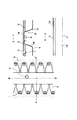
図4および5は本発明による構成を施した典型的なインクジェットプリントヘッド、図6は従来の構成をもつインクジェットプリントヘッドである。これらのプリントヘッドは特開平4−10940号公開公報、特開平4−10941号公開公報に記載のインクジェット記録方法を特徴とするインク滴吐出手段、すなわち吐出時の発泡を外気に連通させる特徴を有するものである。なお、これらのプリントヘッドを駆動するための電気的な配線、ドライバー、手段などは省略してある。なお各図とも、電気熱変換素子を配した基板の正面から見た拡大図およびA−A’、B−B’方向の垂直断面図を示している。
【0018】
まず、インクジェットプリントヘッド内の溶解せずに残った残気泡がいかにして吐出に悪影響を与えるかを説明する。従来のインクジェットプリントヘッドでは、ある時点で供給口の直上付近において吐出口プレート表面に付着(吸着)した残留気泡が、それを核として図6のように成長することが観察などによってわかっている。この残留気泡9は、インク滴の吐出によるインクジェットプリントヘッド内のインク流、具体的にはインク流路へインクを再充填するために生じる吐出口2に向かうインクの流れによって局所的にノズルに引き込まれやすい形状をしている。実際に約150μm程度の残留気泡9が図6のような位置に存在していると、残留気泡9がインク流路内に引き込まれることによってインク流路内のインクが残留気泡によって分断され、インク流路へのインク供給不足を生じてしまう。本発明者らの観察によると、このままさらにインク滴吐出を継続していくと、この残留気泡9が吐出口2側に向かっていき、この残留気泡9が外気と連通した瞬間にインクのメニスカスが破壊されインクジェットプリントヘッド内のインクが空になってしまうという現象が起きていることが判明した。
【0019】
この現象を図3に示す簡単なモデルを用いて説明する。図3において、今、細長い管をインクで満たし、片方の端(A)を大気圧に、もう片方の端(B)を大気圧−P(kPa)に保つ。なお、管へのインクの出入りは自由であるとする。ここで、Pは具体的にはインクジェットプリントヘッドのインクタンクがインクを吸い上げている負圧力である。Aではインクの毛管力によって力の釣り合いが取られており、メニスカスが形成されている。ここで、インク中の径r(μm)をもつ気泡が存在するとし、インクの表面張力をγ(dyn/cm)とすれば、この気泡9の内圧は
【0020】
【数1】
大気圧−P+2γ/r
で表記できる。この状態で気泡9をA側に近づけ、ある時刻にこの気泡9を大気と連通させる。ここで、
【0021】
【数2】
大気圧−P+2γ/r>大気圧
の場合、すなわち
【0022】
【数3】
P<2γ/r
が成立している場合((i)参照)、気泡9内の内圧が大気圧より高いために、ちょうど風船がしぼむように気泡9は大気に排出される。逆に
【0023】
【数4】
大気圧−P+2γ/r<大気圧
の場合、すなわち、
【0024】
【数5】
P>2γ/r
が成立している場合((ii)参照)、気泡9内の内圧が大気圧より低いため、気泡9内に大気から急激な空気の流入があり、管の中は一瞬にして点線のように空気で埋まってしまう。
【0025】
上記の説明からわかるように、ノズルの近傍にP>2γ/rすなわち
【0026】
【数6】
r>2γ/P
となるような大きさの残留気泡が存在する場合、この残留気泡が外気と連通した瞬間にインクジェットプリントヘッド内のインクが空になってしまうという現象が起こり得る。本発明者らの実験では、=47.8dyn/cmのインクを用い、タンク負圧1kPaで確認を行っているが、それから計算される残留気泡の臨界径は95.6μmであり、ほぼ予測と実験結果が一致している。
【0027】
本発明者らはこの残留気泡がインク供給特性に悪影響を与えるほど成長することを抑えるために、先に出願した発明(特願平8−304719)において吐出口プレート内面のインク供給口直上に突起を設け、かつインク流路が、基板のインク供給口からインク吐出エネルギー発生素子との間において隣接する吐出エネルギー発生素子と共有する共有流路を有する構成を提案している。図6のように、インク供給口近傍から各電気熱変換素子まで、それぞれ個別のインク流路で隔離された構成から、図5のようにインク液路が、インク供給口から吐出エネルギー発生素子との間で、隣接しているノズルと共有する共有流路を有する。このように突起および流路に共有部15を設けることによって、吐出口プレートの表面に付着し成長していく残留気泡はこの残留気泡の径が突起の間隙以上には成長せず、一方で、突起の先端部分に付着した残留気泡は成長していくが、共有流路によって図5の矢印で示した広い範囲からインク供給を受けられるため、突起、共有部のないインクジェットプリントヘッドに比較してインク流路内に残留気泡が入り込むことを格段に低減することが可能となる。この構成を好適に作用させるには、具体的には突起間の間隙は10μm以上2γ/P以下であり、主成分が水であるインクを吐出させるインクジェットプリントヘッドにおいては、インクがγ=40〜50dyn/cm、タンク内負圧がP=0.5〜2kPaで使用されることが望ましいため、a=2γ/Pは40μm以上、200μm以下、すなわち突起の間隙を10μm以上40μm以下となるようにすれば、通常用いられるインクジェットプリントヘッドに用いられる各種のγをもつインク、各種のPをもつタンクにおいても好ましく作用するものである。
【0028】
本発明はこの構成をさらに好適に作用させるために、供給口直上のインク流路側の吐出口プレート表面を含め、前記突起部表面を親インク性とした。この部分を親インク性にすることにより、吐出口プレートおよび突起の先端に気泡が付着することは格段に減少する。仮に気泡が付着しても、気泡が成長していく途中のまだインク滴吐出に影響を及ぼさない過程において、気泡は突起先端部分から離れ、インクジェットプリントヘッドの共通液室中に留まるか、インク中に再溶解してしまう。すなわち、本発明が施した構成は、従来に比較して残留気泡が吐出口プレートおよび突起部に付着しにくく、また仮に残留気泡が成長しても残留気泡がインク流路内に引き込まれることによってインク流路内のインクが分断されることはなく、インク流路へのインクの供給不足および大気との連通によるインクジェットプリントヘッド内のインクが空になってしまう現象が非常に生じにくくなっており、安定なインク滴の吐出と信頼性の高いインクジェットプリントヘッドを提供している。
【0029】
以下図面を参照しつつ本発明に係る実施例を詳細に説明する。
【0030】
図1は、本発明の基本的な形態を示すインクジェットプリントヘッドの模式図であり、説明のために適当な面で切断してある。なお、本図およびこれ以下において、電気熱変換素子を駆動するための電気的な配線などは図示していない。図2は、各工程における図1のインクジェットプリント基板のA−A’断面図である。図2は本発明のインクジェットプリントヘッドの製造方法を簡潔に示している。
【0031】
図1において4は吐出エネルギー発生素子1およびインク供給口3を備える基板であり、長溝状の貫通口からなるインク供給口3の長手方向の両側に吐出エネルギー発生素子1である電気熱変換素子がそれぞれ1列ずつ千鳥状に、また電気熱変換素子の間隔が片側列300dpiピッチで配列されている。この基板4上にはインク流路を形成するためのインク流路壁となる被覆樹脂層6が設けられており、この被覆樹脂層6上にさらに吐出口2を備える吐出口プレート5が設けられている。ここで図1において被覆樹脂層6と吐出口プレート5とは別部材として示されているが、この被覆樹脂層6をスピンコートなどの手法によって基板4上に形成することにより、被覆樹脂層6と吐出口プレート5とを同一部材として同時に形成することも可能である。7は吐出口プレート内面のインク供給口3直上に設けられる突起である。さらにここではインク流路が、基板のインク供給口からインク吐出エネルギー発生素子との間で、隣接する吐出エネルギー発生素子と共有する共有流路部を有する構成となっている。具体的には各電気熱変換素子毎の個別のインク流路を形成するための隔離壁がインク供給口まで達していない構成となっている。突起の形状としてはインク流路の流抵抗をできるだけ小さくする観点からインク供給口3から吐出口2に向かうインクの流れ方向に沿うリブによって構成されることが好ましいが、前述の間隙の範囲を満たすものであれば、例えば複数の柱からなるような形状であっても構わない。また、インク供給性の観点からは突起が基板から離間していることが望ましく、さらにこのときの突起の離間距離は突起の端部から基板までの最短距離が前述の間隙同様10〜40μmの範囲に収まっていることが望ましい。また、突起7が上述のインクの流れ方向に沿うリブで形成されている場合には、このリブを基板と接触させることにより、吐出口プレートの強度を向上させることもできる。さらにこのとき、リブの端部をテーパー形状とすることによってインク流路のインク流抵抗を小さくすることも可能である。また、図1においては、突起7の高さとインク流路壁6の高さが同じになっているが、突起7の高さは必ずしもインク流路壁の高さと同じにする必要はなく、このときも前述同様突起の端部から基板までの最短距離が、前述の間隙同様に10〜40μmの範囲に収まっているように形成されていれば構わない。
【0032】
図2のHで示した14は親インク性をもつ面(膜)を表し、上述のように供給口3の直上の突起7を含む吐出口プレート5の内面である。この面を親インク性にすることによりインクジェットプリントヘッド内部に残った気泡のインク滴吐出に与える悪影響を格段に緩和させることができるものである。
【0033】
以下に本発明のインクジェットプリントヘッドの製造方法の一例を示す。
【0034】
まず、Siチップ上にパターニングなどによって複数の電気熱変換素子およびそれらを駆動するための必要な配線(不図示)が施された基板4を用意し(図2−A)、該基板4上に溶解可能な樹脂層12を形成する(図2−B)。前記樹脂層12において、フォトレジスト法などを用いてインク流路パターンを残すとともに、ノズル壁および供給口が形成される箇所の上方に適当な突起に相当する部分を除去する(図2−C)。さらにこのようなインク流路パターンが形成された溶解可能な樹脂層12’上に、被覆樹脂層6を形成させ(図2−D)、前記被覆樹脂層6で吐出口2に相当する部分を除去する(図2−E)。次に基板4を背面より、基板を化学的にエッチングするなどして供給口3を形成する(図2−F)。より具体的には、強アルカリ溶液(KOH,NaOH,TMAH)を用いた異方性エッチングによって供給口3を形成する。最後の溶解可能な樹脂層12’を溶出させる(図2−G)ことにより、吐出口2、供給口3とそれらに連通する流路および供給口直上のオリフィスプレート側面に形成された突起部7を備えたインクジェットプリントチップを得ることができる。
【0035】
本発明のインクジェットプリントヘッドにおいては、例えば、この状態でさらに基板4の背面より、供給口3を介して吐出口プレート5の内面と突起部7を親インク処理することにより形成することができる。具体的にはオゾンガスによる突起7を含む吐出口プレート5の内面の酸化処理、もしくは親インク性をもつ無機酸化物(SiO2 ,Al2 O3 など)をスパッタリングなどの適当な手段を用いて突起7を含む吐出口プレ−ト5の内面に親インク被膜を形成されることができる(図2−H)。このチップに電気熱変換素子を駆動するための電気的接合などを行うことにより本発明のインクジェットプリントヘッドを得ることができる。
【0036】
上記のインクジェットプリントヘッドの製造法は、特に特開平4−10940号公開公報、特開平4−10941号公開公報に記載のインクジェット記録方法をインク滴吐出手段とするインクジェットプリントヘッドの製造に採用することが好ましい。これらの各公報は、記録信号によって生じた電気熱変換素子上の気泡を外気と連通させることを特徴とするインク滴吐出方法を開示したものであり、小インク滴(50pl以下)の吐出を可能にするインクジェットプリントヘッドを提供している。このインクジェットプリントヘッドは、気泡を外気と連通させるため、吐出インク滴の体積は、電気熱変換素子と吐出口間の体積のみにほとんど依存する、言い換えるとインクジェットプリントヘッドのノズル部分の構造によってほぼ決まるという特徴を有する。したがって、前記インクジェットプリントヘッドは、ムラのない高品位な画像を出力することができる。本発明の構造は前記のインクジェットプリントヘッド、すなわち、気泡を外気と連通させるために、電気熱変換素子と吐出口間の(最短)距離が30μm以下であるようなインクジェットプリントヘッドに適用することで最大の効果を発揮するが、電気熱変換素子を配した基板面に垂直にインク液滴を飛翔させるようなインクジェットプリントヘッドであれば、いずれも有効に作用させることができる。
【0037】
また、本発明のインクジェットプリントヘッドにおいては、隣接する電気熱変換素子を同時に駆動させないように、分散駆動により各電気熱変換素子を駆動させることによって残留気泡による悪影響をさらに効果的に緩和できるものである。
【0038】
【実施例】
以下、本発明のインクジェットプリントヘッドの構成を実施例により具体的に説明する。なお各実施例については、いずれも前述の図2−A〜Hに示す手順にしたがって作成したインクジェットプリントヘッドを使用し、ノズル間隔は片側例300dpiピッチ、オリフィスプレートの肉厚8μm、本発明の特徴である突起およびノズル壁の高さは12μmである。評価に使用したインクは、キャノン製染料系ブラックインク(表面張力47.8dyn/cm,粘度1.8cp,pH9.8)を使用した。
【0039】
実施例1
本実施例のインクジェットプリントヘッドを電気熱変換素子を配した基板の正面から見た拡大図と、A−A’,B−B’断面図をまとめて図4に示した。
【0040】
本実施例は構造が従来のインクジェットプリントヘッドと同一であるが、供給口直上の吐出プレートの内面が親インク処理されている。このプリントヘッドを作成するにあたっての親インク処理は、オゾンガスによるノズル壁および吐出プレート面を酸化する方法を採用している。
【0041】
本実施例のインクジェットプリントヘッドを吐出周波数10kHzで駆動し、黒ベタを連続記録してその持続時間を計測し、比較評価を行った。約2e+05発相当のインク滴連続吐出において、従来のインクジェットプリントヘッドでは約100μm程度の残留気泡が複数個吐出口プレート面に付着していたのに対し、本実施例では吐出口プレート面に細かい(約20〜50μm)残留気泡が複数付着しているのが観察されたが、これは前述したようなインク滴を悪影響を及ぼすようなサイズではない。また、連続吐出の持続性能は、従来のインクジェットプリントヘッドに比較して、本実施例では実に2倍程度も長い間黒ベタを印字することができた。
【0042】
実施例2
本実施例のインクジェットプリントヘッドを、電気熱変換素子を配した基板の正面から見た拡大図と、A−A’,B−B’断面図をまとめて図4に示した。
【0043】
本実施例では突起が基板と吐出プレートの両方に接することで吐出プレートの強度を上げ、かつノズルへのインク供給を確保し、流抵抗を抑えるために突起の吐出口プレートに平行な面における幅が電気熱変換素子に向かって連続的に細くなっていくことを特徴としている。突起の吐出口プレート面への射影の幅は、太いところで20μmであり、細いところで12μmである。突起の長手方向の寸法は200μmであり、各突起間は間隔600dpiピッチ(42.3μm)で並んでいる。すなわち、突起と突起の間隙は最低でも22.3μmある構成である。本実施例のインクジェットプリントヘッドは、供給口直上の吐出口プレートの内面と突起部にSiO2 をスパッタリングして親インク性をもつSiO2 膜を成膜することによって親インク処理されている。
【0044】
本実施例のインクジェットプリントヘッドを吐出周波数10kHzで駆動し、黒ベタを連続記録してその持続時間を計測し、比較評価を行った。約5e+05発相当のインク滴連続吐出において、親インク処理されていない本実施例と同一の構造をもつインクジェットプリントヘッドでは約100μm程度の残留気泡が複数個吐出口プレート面に付着していたのに対し、本実施例では吐出口プレート面に細かい(約20〜50μm)残留気泡が複数付着しているのが観察されたが、これは前記したようなインク滴を悪影響を及ぼすようなサイズではない。また、連続吐出の持続性能は、従来のインクジェットプリントヘッドに比較して、本実施例では実に7倍程度も長い間黒ベタを印字することができた。
【0045】
【発明の効果】
以上説明したように、本発明によれば、インクジェットプリントヘッド内部に残った気泡のインク滴吐出に与える悪影響を格段に緩和させ、安定なインク滴の吐出と信頼性の高いインクジェットプリントヘッドを提供することができる。また、残留気泡を制御することにより回復処理を頻繁に行う必要もなくなるため、スループットの向上やインク消費量の低減といった効果をも奏するものである。
【図面の簡単な説明】
【図1】本発明の基本的な形態を示すインクジェットプリントヘッドの模式図である。
【図2】本発明のインクジェットプリントヘッドの製造方法を説明するための説明図である。
【図3】インクジェットプリントヘッド内の残留気泡の様子を説明するための説明図である。
【図4】実施例1に係るインクジェットプリントヘッドを示す模式図である。
【図5】実施例2に係るインクジェットプリントヘッドを示す模式図である。
【図6】従来例のインクジェットプリントヘッドを示す模式図である。
【符号の説明】
1 吐出エネルギー発生素子
2 吐出口
3 供給口
4 基板
5 吐出口プレート
6 被覆樹脂層(ノズル壁)
7 突起
8 インク
9 残留気泡
10 ノズルに向かうインクの流れの向き
11 インクの流れによって生じる残留気泡の変形分
12 溶解可能な樹脂層
13 インク流路パターン
14 親インク面(親インク膜)
15 共有部[0001]
TECHNICAL FIELD OF THE INVENTION
The present invention relates to an ink jet print head used in an ink jet recording system for ejecting ink droplets and performing recording on a recording medium, and an ink jet print system using the head.
[0002]
[Prior art]
The ink jet recording method is one of the so-called non-impact recording methods. As a feature of this recording method, the generation of noise at the time of recording is so small that it can be ignored, high-speed recording and recording on various recording media are possible, and no special processing is required for so-called plain paper. And high-definition images can be obtained at low cost. Due to these advantages, in recent years, printing systems such as copying machines, facsimile machines, word processors and the like as well as printers as peripheral devices of computers have rapidly spread.
[0003]
Ink jet recording methods widely used today include an ink discharge method using an electrothermal transducer (heater) and a method using a piezoelectric element (piezo). In each case, the ejection of ink droplets can be controlled by an electric signal. For example, the principle of an ink droplet ejection method using an electrothermal transducer is that an electric signal is applied to the electrothermal transducer to instantaneously boil the ink near the electrothermal transducer and change the phase of the ink at that time. The ink droplets are ejected at a high speed by the rapid growth of the generated bubbles. On the other hand, the principle of the method of ejecting ink droplets using a piezoelectric element is that the piezoelectric element is displaced by applying an electric signal to the piezoelectric element, and the ink droplet is ejected by the pressure at the time of this displacement.
[0004]
Here, the former method does not require much space for the ejection energy generating element, and has advantages such as a simple structure of the ink jet print head and easy integration of nozzles. On the other hand, the disadvantages inherent in this method include the volume fluctuation of flying ink droplets due to the heat generated in the ink jet print head due to the heat generated by the electrothermal transducer, the effect of cavitation due to defoaming on the electrothermal transducer, and the melting of the ink into the ink. There is an effect on ink drop ejection characteristics and an image due to residual air bubbles in the inkjet print head due to air.
[0005]
As methods for solving these drawbacks, JP-A-54-161935, JP-A-61-185455, JP-A-61-249768, JP-A-4-10940, and JP-A-4-10940 are disclosed. There is an ink jet recording method and an ink jet print head described in JP-A-4-10941. That is, the ink jet recording method described in the above publication is characterized in that bubbles generated on the electrothermal transducer by a recording signal are communicated with the outside air. By using this recording method, it is possible to improve the volume stability of flying ink droplets, discharge high-speed droplets, and improve the durability of heaters by eliminating cavitation that occurs when bubbles are eliminated, facilitating higher-definition images. Will be obtained.
[0006]
In the above publication, as a configuration for communicating bubbles with the outside air, a configuration in which the distance between the electrothermal conversion element and the discharge port is much shorter than in the related art is cited. The ink jet print head having this configuration has a substrate plate disposed at a discharge port corresponding to the electrothermal transducer, and an ink supply port opened in the substrate to supply ink from the back of the substrate. The droplet is configured to fly almost perpendicularly to the substrate on which the electrothermal conversion elements are arranged (FIGS. 1 and 6). Here, it is desirable that the (shortest) distance between the electrothermal conversion element and the discharge port be 30 μm or less.
[0007]
[Problems to be solved by the invention]
By the way, the effect on the ink droplet ejection characteristics of ink remaining in the ink jet print head and the effect on the image due to air dissolved in the ink, which is one of the drawbacks due to the configuration described in the above-mentioned publication, cannot be sufficiently solved yet. It has been found that this problem is more likely to appear remarkably because the height of the flow path is low.
[0008]
Hereinafter, the ink droplet ejection characteristics of the residual bubbles in the ink jet print head and the effect on the image due to the air dissolved in the ink will be described in detail. In the ink in the ink jet print head, air is usually dissolved in a saturated state. When the electrothermal transducer is driven in this state, when the foaming due to the phase change of the ink and the rapid adiabatic shrinkage of the bubbles are repeated, the air dissolved in the ink becomes undissolved bubbles having a diameter of about 1 μm or less. May appear suddenly in ink. It is known that such bubbles are redissolved in the ink in a time determined by the diameter of the bubble, the surface tension of the ink, the saturated vapor pressure of the air, the solubility, and the like. If the bubbles are 1 μm or less, the time required for dissolution is on the order of 1 μs or less. However, when a plurality of electrothermal transducers are continuously driven at a high frequency, such bubbles appear in the ink and coalesce and grow with each other before being re-dissolved. It is known that as the bubble diameter increases, the time required for re-dissolution increases significantly, but as a result, a plurality of residual bubbles on the order of several tens of μm to several hundreds of μm are stored in the inkjet print head. In such a case, these residual bubbles hardly redissolve in the ink, and have a very bad influence on the ejection characteristics of the ink droplets. In other words, if the residual air bubbles block the ink flow path, the nozzles are not filled with sufficient ink, causing ejection failure. In addition, huge residual air bubbles inside the ink jet print head, for example, about 100 μm, are generated, and when such residual air bubbles happen to be communicated with the outside air, the outside air enters the nozzle and the meniscus is destroyed. Therefore, the negative pressure for sucking up the ink in the ink tank may cause the ink inside the ink jet print head to be sucked up into the ink tank and cause all the nozzles to fail to discharge.
[0009]
The most effective solution to avoid such adverse effects caused by the residual air bubbles is to discharge the ink along with the ink by suction, pressurization, or the like to the outside from the ejection port before the residual air bubbles grow so badly that the so-called suction ( There is a method of performing a (pressure) recovery process. However, in this case, the consumption of ink is significantly increased, and if this is performed during printing, the throughput naturally decreases.
[0010]
Another method is to expel air that has been dissolved in the ink from the ink by some method (degassing) and use such ink for an inkjet printhead. Most of the time, this solution works effectively only for several tens of minutes after degassing the ink and then exposing it to the air, and the device for degassing the ink is relatively large. The technique can be used only for large-scale printing systems.
[0011]
[Means for Solving the Problems]
The present invention has been made in view of the above problems. It is an object of the present invention to provide an ink jet print head which reduces the adverse effect of air bubbles remaining inside an ink jet print head on ink droplet discharge, stably discharges ink droplets and has high reliability, and a method of manufacturing the same.
[0012]
Another object of the present invention is to provide an ink-jet printing device which is excellent in throughput by controlling residual air bubbles and reducing the number of times of recovery processing, and consumes a small amount of ink.
[0013]
To achieve the above object, the configuration of the present invention comprises a plurality of ejection energy generating elements for generating energy used for ejecting ink droplets, an ink ejection port for ejecting the ink droplets, and the plurality of ejection energy generating elements. A substrate having an ink supply port composed of a through-hole that is arranged in a row and extends along the direction of arrangement of the discharge energy generating elements, and a discharge port plate including the ink discharge port, wherein the substrate and the In an ink-jet printhead in which a discharge port plate is joined and an ink flow path communicating between the ink discharge port and the ink supply port is formed between the substrate and the discharge port plate, the ink supply port of the discharge port plate is provided. The surface on the ink flow path side corresponding to the projection of the ejection port plate is compared with the other surface and the ink flow path surface of the discharge port plate. It is characterized in that the high ink resistance.
[0014]
As a more preferable configuration, in addition to the above-described configuration, the discharge port plate further has a plurality of protrusions at positions corresponding to the ink supply ports, and the ink flow path is configured such that the ink discharge energy from the ink supply port of the substrate is A common flow path portion shared with the adjacent ejection energy generating element between the generating element, and the surface of the projection portion has a surface of an ink flow path corresponding to the projection of the ink supply port of the discharge port plate. The ink is characterized by having the same or higher ink affinity. Here, the ink-philic property means that the contact angle of the test-ink-treated surface with respect to the test-ink contact angle between the ink-treated surface and the untreated surface is low.
[0015]
Further, the method of manufacturing the ink jet print head is characterized in that an ink-philic treatment is performed at a position corresponding to the ink supply port of the ejection plate from the back surface of the substrate through the through-hole.
[0016]
BEST MODE FOR CARRYING OUT THE INVENTION
First, the operation of the configuration of the present invention will be described in detail below with reference to the drawings and the like in comparison with a conventional example.
[0017]
4 and 5 show a typical ink jet print head having the configuration according to the present invention, and FIG. 6 shows an ink jet print head having a conventional configuration. These print heads have an ink droplet ejection means characterized by the ink jet recording method described in JP-A-4-10940 and JP-A-4-10941, that is, have a feature of communicating foaming during ejection to the outside air. Things. Note that electrical wiring, drivers, means, and the like for driving these print heads are omitted. Each drawing shows an enlarged view as viewed from the front of the substrate on which the electrothermal conversion elements are arranged, and a vertical cross-sectional view in the AA 'and BB' directions.
[0018]
First, how the residual air bubbles remaining without being dissolved in the ink jet print head affect the ejection will be described. It is known from observations and the like that in the conventional ink jet print head, residual air bubbles adhering (adsorbed) to the surface of the discharge port plate near the supply port at a certain point grow as a nucleus as shown in FIG. The
[0019]
This phenomenon will be described using a simple model shown in FIG. In FIG. 3, the elongated tube is now filled with ink and one end (A) is kept at atmospheric pressure and the other end (B) is kept at atmospheric pressure-P (kPa). It is assumed that ink can freely enter and exit the tube. Here, P is a negative pressure at which the ink tank of the ink jet print head is sucking up the ink. In A, the forces are balanced by the capillary force of the ink, and a meniscus is formed. Here, assuming that bubbles having a diameter r (μm) exist in the ink and the surface tension of the ink is γ (dyn / cm), the internal pressure of the
[0020]
(Equation 1)
Atmospheric pressure-P + 2γ / r
Can be represented by In this state, the
[0021]
(Equation 2)
Atmospheric pressure-P + 2γ / r> Atmospheric pressure
, That is,
[0022]
(Equation 3)
P <2γ / r
Is satisfied (see (i)), since the internal pressure in the
[0023]
(Equation 4)
Atmospheric pressure-P + 2γ / r <Atmospheric pressure
, That is,
[0024]
(Equation 5)
P> 2γ / r
Is satisfied (see (ii)), since the internal pressure in the
[0025]
As can be seen from the above description, P> 2γ / r near the nozzle, ie,
[0026]
(Equation 6)
r> 2γ / P
When a residual bubble having such a size as to exist exists, a phenomenon that the ink in the ink jet print head becomes empty at the moment when the residual bubble communicates with the outside air may occur. In the experiment of the present inventors, the ink was checked at 47.8 dyn / cm and the tank negative pressure was 1 kPa, and the critical diameter of the residual bubble calculated from that was 95.6 μm, which was almost the same as the prediction. The experimental results are consistent.
[0027]
In order to suppress the residual air bubbles from growing so as to adversely affect the ink supply characteristics, the inventors of the present invention (Japanese Patent Application No. 8-304719) propose a method in which a protrusion is formed just above the ink supply port on the inner surface of the ejection port plate. , And a configuration in which the ink flow path has a shared flow path shared with the adjacent discharge energy generation element between the ink supply port of the substrate and the ink discharge energy generation element. As shown in FIG. 6, from the configuration near the ink supply port to each electrothermal conversion element, the ink liquid path is separated from the ink supply port to the ejection energy generating element from the ink supply port as shown in FIG. Has a shared flow path shared with adjacent nozzles. By providing the
[0028]
According to the present invention, in order to make this structure work more suitably, the surface of the projection portion, including the surface of the ejection port plate on the ink flow path side immediately above the supply port, is made ink-philic. By making this portion ink-philic, the adhesion of bubbles to the ejection port plate and the tip of the projection is significantly reduced. Even if air bubbles adhere, in the process where the air bubbles are growing and do not affect the ink droplet ejection yet, the air bubbles will leave the tip of the protrusion and remain in the common liquid chamber of the inkjet print head, or Will be dissolved again. That is, in the configuration of the present invention, the residual air bubbles are less likely to adhere to the ejection port plate and the protrusions than in the past, and even if the residual air bubbles grow, the residual air bubbles are drawn into the ink flow path. The ink in the ink flow path is not divided, and the phenomenon that the ink in the ink jet print head becomes empty due to insufficient supply of ink to the ink flow path and communication with the atmosphere is very unlikely to occur. And a highly reliable ink jet print head with stable ink droplet ejection.
[0029]
Hereinafter, embodiments of the present invention will be described in detail with reference to the drawings.
[0030]
FIG. 1 is a schematic view of an ink-jet printhead showing a basic mode of the present invention, which is cut at an appropriate plane for explanation. In addition, in this figure and below, electric wiring for driving the electrothermal transducer is not shown. FIG. 2 is a cross-sectional view of the inkjet printed circuit board of FIG. FIG. 2 briefly shows a method of manufacturing the ink jet print head of the present invention.
[0031]
In FIG. 1,
[0032]
[0033]
Hereinafter, an example of the method for manufacturing the ink jet print head of the present invention will be described.
[0034]
First, a
[0035]
In the ink jet print head of the present invention, for example, in this state, the inner surface of the
[0036]
The method for manufacturing an ink jet print head described above is particularly adopted for manufacturing an ink jet print head using the ink jet recording method described in JP-A-4-10940 and JP-A-4-10941 as an ink droplet discharging means. Is preferred. Each of these publications discloses an ink droplet ejection method characterized in that bubbles on an electrothermal transducer generated by a recording signal are communicated with the outside air, and is capable of ejecting small ink droplets (50 pl or less). To provide inkjet printheads. In this ink jet print head, since the bubbles communicate with the outside air, the volume of the ejected ink droplet almost depends only on the volume between the electrothermal transducer and the ejection port, in other words, it is substantially determined by the structure of the nozzle portion of the ink jet print head. It has the feature. Therefore, the inkjet print head can output a high-quality image without unevenness. The structure of the present invention can be applied to the above-described ink jet print head, that is, an ink jet print head in which the (shortest) distance between the electrothermal transducer and the discharge port is 30 μm or less in order to allow air bubbles to communicate with the outside air. Although the maximum effect is exhibited, any ink jet print head that can fly ink droplets perpendicularly to the substrate surface on which the electrothermal conversion elements are arranged can be effectively used.
[0037]
Further, in the ink jet print head of the present invention, the adverse effects due to residual bubbles can be more effectively mitigated by driving each electrothermal conversion element by distributed driving so as not to simultaneously drive adjacent electrothermal conversion elements. is there.
[0038]
【Example】
Hereinafter, the configuration of the inkjet print head of the present invention will be specifically described with reference to examples. In each of the embodiments, an ink jet print head prepared in accordance with the procedure shown in FIGS. 2A to 2H was used, the nozzle interval was 300 dpi on one side, the thickness of the orifice plate was 8 μm, and the features of the present invention. The height of the projection and the nozzle wall is 12 μm. The ink used for the evaluation was a dye-based black ink manufactured by Canon (surface tension 47.8 dyn / cm, viscosity 1.8 cp, pH 9.8).
[0039]
Example 1
FIG. 4 shows an enlarged view of the inkjet print head of the present embodiment as viewed from the front of the substrate on which the electrothermal conversion elements are arranged, and a cross-sectional view taken along the lines AA ′ and BB ′.
[0040]
In this embodiment, the structure is the same as that of the conventional ink jet print head, but the inner surface of the discharge plate immediately above the supply port is treated with ink-friendly ink. The ink-friendly treatment for producing this print head employs a method of oxidizing the nozzle wall and the discharge plate surface with ozone gas.
[0041]
The inkjet print head of this example was driven at an ejection frequency of 10 kHz, black solids were continuously recorded, the duration was measured, and comparative evaluation was performed. In continuous ejection of ink droplets equivalent to about 2e + 05 shots, in the conventional ink jet print head, a plurality of residual bubbles of about 100 μm adhered to the ejection port plate surface, whereas in the present embodiment, fine bubbles were formed on the ejection port plate surface ( (Approximately 20 to 50 μm) A plurality of residual air bubbles were observed to adhere, but this is not a size that adversely affects the ink droplet as described above. Further, the continuous discharge performance was able to print solid black for about twice as long in this embodiment as compared with the conventional ink jet print head.
[0042]
Example 2
FIG. 4 shows an enlarged view of the inkjet print head of the present embodiment as viewed from the front of the substrate on which the electrothermal transducers are arranged, and sectional views taken along lines AA ′ and BB ′.
[0043]
In this embodiment, the projections contact both the substrate and the ejection plate to increase the strength of the ejection plate, secure the ink supply to the nozzles, and reduce the flow resistance of the projections in the plane parallel to the ejection port plate. Are characterized in that they continuously narrow toward the electrothermal conversion element. The width of the projection of the projection onto the discharge port plate surface is 20 μm at a thick position and 12 μm at a thin position. The lengths of the projections in the longitudinal direction are 200 μm, and the projections are arranged at intervals of 600 dpi (42.3 μm). That is, the gap between the projections is at least 22.3 μm. In the ink jet print head of this embodiment, the inner surface of the discharge port plate just above the supply port and the protrusion are formed of SiO. 2 Which has ink affinity by sputtering 2 The ink-philic treatment is performed by forming a film.
[0044]
The inkjet print head of this example was driven at an ejection frequency of 10 kHz, black solids were continuously recorded, the duration was measured, and comparative evaluation was performed. In continuous ejection of ink droplets equivalent to about 5e + 05 shots, in the ink jet print head having the same structure as that of the present embodiment, which was not subjected to the ink-philic treatment, a plurality of residual bubbles of about 100 μm adhered to the ejection port plate surface. On the other hand, in the present embodiment, it was observed that a plurality of fine (about 20 to 50 μm) residual bubbles adhered to the ejection port plate surface, but this is not a size that adversely affects the ink droplet as described above. . In addition, the continuous discharge performance was able to print solid black for about 7 times as long in this embodiment as compared with the conventional inkjet print head.
[0045]
【The invention's effect】
As described above, according to the present invention, the adverse effect of the bubbles remaining inside the ink jet print head on the ink droplet ejection is remarkably reduced, and a stable ink droplet ejection and a highly reliable ink jet print head are provided. be able to. Further, by controlling the residual air bubbles, it is not necessary to frequently perform the recovery process, so that the effects such as an improvement in throughput and a reduction in ink consumption can be achieved.
[Brief description of the drawings]
FIG. 1 is a schematic view of an ink jet print head showing a basic mode of the present invention.
FIG. 2 is an explanatory diagram illustrating a method for manufacturing an ink jet print head of the present invention.
FIG. 3 is an explanatory diagram for explaining a state of a residual bubble in an inkjet print head.
FIG. 4 is a schematic view illustrating an inkjet print head according to the first embodiment.
FIG. 5 is a schematic view illustrating an inkjet print head according to a second embodiment.
FIG. 6 is a schematic view showing a conventional inkjet print head.
[Explanation of symbols]
1 Discharge energy generating element
2 Discharge port
3 Supply port
4 Substrate
5 Discharge port plate
6 coating resin layer (nozzle wall)
7 Projection
8 ink
9 residual air bubbles
10 Direction of ink flow toward nozzle
11 Deformation of residual bubbles caused by ink flow
12 Soluble resin layer
13 Ink channel pattern
14. Ink-friendly surface (ink-insensitive film)
15 Common part
Claims (19)
前記吐出口プレートの前記インク供給口の射影に相当するインク流路側の表面が、前記吐出口プレートのそれ以外の表面およびインク流路表面に比較して親インク性が高いことを特徴とするインクジェットプリントヘッド。A plurality of ejection energy generating elements for generating energy used for ejecting ink droplets; an ink ejection port for ejecting the ink droplets; A substrate having an ink supply port formed of a through-hole extending along the arrangement direction of the elements, and a discharge port plate having the ink discharge port, wherein the substrate and the discharge port plate are joined, and the substrate and the discharge port are provided. An ink jet print head in which an ink flow path communicating the ink discharge port and the ink supply port is formed between the plate and the ink discharge port.
Ink-jet printing, wherein the surface of the discharge port plate on the side of the ink flow path corresponding to the projection of the ink supply port has higher ink affinity than the other surface of the discharge port plate and the surface of the ink flow path. Print head.
Priority Applications (5)
| Application Number | Priority Date | Filing Date | Title |
|---|---|---|---|
| JP33605297A JP3559698B2 (en) | 1997-12-05 | 1997-12-05 | INK JET PRINT HEAD, INK JET PRINTING DEVICE, AND THEIR MANUFACTURING METHOD |
| US09/203,394 US6540335B2 (en) | 1997-12-05 | 1998-12-02 | Ink jet print head and ink jet printing device mounting this head |
| ES98122935T ES2241093T3 (en) | 1997-12-05 | 1998-12-03 | THERMAL PRINT HEAD BY INK JETS WITH AN ELEMENT OF RESIDENCE TO THE FLUID IN A CHANNEL. |
| EP98122935A EP0921001B1 (en) | 1997-12-05 | 1998-12-03 | Thermal ink jet printhead with fluid flow resisting member in channel |
| DE69830380T DE69830380T2 (en) | 1997-12-05 | 1998-12-03 | Thermal inkjet printhead with liquid flow resistance |
Applications Claiming Priority (1)
| Application Number | Priority Date | Filing Date | Title |
|---|---|---|---|
| JP33605297A JP3559698B2 (en) | 1997-12-05 | 1997-12-05 | INK JET PRINT HEAD, INK JET PRINTING DEVICE, AND THEIR MANUFACTURING METHOD |
Publications (2)
| Publication Number | Publication Date |
|---|---|
| JPH11170530A JPH11170530A (en) | 1999-06-29 |
| JP3559698B2 true JP3559698B2 (en) | 2004-09-02 |
Family
ID=18295213
Family Applications (1)
| Application Number | Title | Priority Date | Filing Date |
|---|---|---|---|
| JP33605297A Expired - Fee Related JP3559698B2 (en) | 1997-12-05 | 1997-12-05 | INK JET PRINT HEAD, INK JET PRINTING DEVICE, AND THEIR MANUFACTURING METHOD |
Country Status (1)
| Country | Link |
|---|---|
| JP (1) | JP3559698B2 (en) |
Families Citing this family (2)
| Publication number | Priority date | Publication date | Assignee | Title |
|---|---|---|---|---|
| US7370944B2 (en) * | 2004-08-30 | 2008-05-13 | Eastman Kodak Company | Liquid ejector having internal filters |
| JP4495671B2 (en) * | 2004-12-27 | 2010-07-07 | 積水化学工業株式会社 | Method for manufacturing liquid crystal display device, spacer particle dispersion, and liquid crystal display device |
-
1997
- 1997-12-05 JP JP33605297A patent/JP3559698B2/en not_active Expired - Fee Related
Also Published As
| Publication number | Publication date |
|---|---|
| JPH11170530A (en) | 1999-06-29 |
Similar Documents
| Publication | Publication Date | Title |
|---|---|---|
| US6137510A (en) | Ink jet head | |
| JP3675272B2 (en) | Liquid discharge head and method for manufacturing the same | |
| JP4459037B2 (en) | Liquid discharge head | |
| JP3957851B2 (en) | Liquid ejection method | |
| US6966112B2 (en) | Methods of fabricating FIT firing chambers of different drop weights on a single printhead | |
| JP3408130B2 (en) | Ink jet recording head and method of manufacturing the same | |
| JPH0452220B2 (en) | ||
| JP2656481B2 (en) | Inkjet recording head | |
| US6805432B1 (en) | Fluid ejecting device with fluid feed slot | |
| JPH1199649A (en) | Ink jet head, manufacture thereof, and ink jet unit | |
| US6609784B2 (en) | Ink jet recording device and a method for designing the same | |
| US6488366B1 (en) | Fluid ejecting device with anchor grooves | |
| JP3581504B2 (en) | Inkjet print head | |
| JP3473668B2 (en) | Ink jet recording head | |
| US7478476B2 (en) | Methods of fabricating fit firing chambers of different drop wights on a single printhead | |
| US6508946B1 (en) | Method for manufacturing ink jet recording head, ink jet recording head, and ink jet recording apparatus | |
| JP4018272B2 (en) | Ink jet print head and ink jet printing device equipped with the head | |
| JP3559698B2 (en) | INK JET PRINT HEAD, INK JET PRINTING DEVICE, AND THEIR MANUFACTURING METHOD | |
| US6530648B2 (en) | Apparatus for using bubble as virtual valve to eject ink and fabricating method thereof | |
| US6910758B2 (en) | Substrate and method of forming substrate for fluid ejection device | |
| JPH10181021A (en) | Ink jet head, ink jet printing device, and ink jet printing method | |
| JP3684046B2 (en) | Ink jet recording head and ink jet recording apparatus | |
| JP4292841B2 (en) | Ink jet recording head and ink jet recording apparatus | |
| JPH11188876A (en) | Ink jet recording head, and ink jet recording apparatus equipped therewith | |
| JP2001171117A (en) | Ink jet recording head |
Legal Events
| Date | Code | Title | Description |
|---|---|---|---|
| TRDD | Decision of grant or rejection written | ||
| A01 | Written decision to grant a patent or to grant a registration (utility model) |
Free format text: JAPANESE INTERMEDIATE CODE: A01 Effective date: 20040512 |
|
| A61 | First payment of annual fees (during grant procedure) |
Free format text: JAPANESE INTERMEDIATE CODE: A61 Effective date: 20040524 |
|
| R150 | Certificate of patent (=grant) or registration of utility model |
Free format text: JAPANESE INTERMEDIATE CODE: R150 |
|
| FPAY | Renewal fee payment (prs date is renewal date of database) |
Free format text: PAYMENT UNTIL: 20090528 Year of fee payment: 5 |
|
| FPAY | Renewal fee payment (prs date is renewal date of database) |
Free format text: PAYMENT UNTIL: 20100528 Year of fee payment: 6 |
|
| FPAY | Renewal fee payment (prs date is renewal date of database) |
Year of fee payment: 6 Free format text: PAYMENT UNTIL: 20100528 |
|
| FPAY | Renewal fee payment (prs date is renewal date of database) |
Free format text: PAYMENT UNTIL: 20110528 Year of fee payment: 7 |
|
| LAPS | Cancellation because of no payment of annual fees |