JP3559620B2 - Printer system - Google Patents
Printer system Download PDFInfo
- Publication number
- JP3559620B2 JP3559620B2 JP18923595A JP18923595A JP3559620B2 JP 3559620 B2 JP3559620 B2 JP 3559620B2 JP 18923595 A JP18923595 A JP 18923595A JP 18923595 A JP18923595 A JP 18923595A JP 3559620 B2 JP3559620 B2 JP 3559620B2
- Authority
- JP
- Japan
- Prior art keywords
- printer
- print command
- command
- output
- Prior art date
- Legal status (The legal status is an assumption and is not a legal conclusion. Google has not performed a legal analysis and makes no representation as to the accuracy of the status listed.)
- Expired - Fee Related
Links
Images


Classifications
-
- Y—GENERAL TAGGING OF NEW TECHNOLOGICAL DEVELOPMENTS; GENERAL TAGGING OF CROSS-SECTIONAL TECHNOLOGIES SPANNING OVER SEVERAL SECTIONS OF THE IPC; TECHNICAL SUBJECTS COVERED BY FORMER USPC CROSS-REFERENCE ART COLLECTIONS [XRACs] AND DIGESTS
- Y02—TECHNOLOGIES OR APPLICATIONS FOR MITIGATION OR ADAPTATION AGAINST CLIMATE CHANGE
- Y02D—CLIMATE CHANGE MITIGATION TECHNOLOGIES IN INFORMATION AND COMMUNICATION TECHNOLOGIES [ICT], I.E. INFORMATION AND COMMUNICATION TECHNOLOGIES AIMING AT THE REDUCTION OF THEIR OWN ENERGY USE
- Y02D10/00—Energy efficient computing, e.g. low power processors, power management or thermal management
Landscapes
- Accessory Devices And Overall Control Thereof (AREA)
Description
【0001】
【発明の属する技術分野】
本発明は情報処理装置及びその情報処理方法に関する。
【0002】
【従来の技術】
従来のホストコンピュータ(以下、ホストという)とプリンタ等で構成されるプリンタシステムにおける、ホスト側からのプリンタの電源制御は、省エネルギモードと通常モードという2つの動作モードの内、いづれか1つを利用者が選択指定し、その選択されたモードに従って実行されていた。この場合、省エネルギモードが選択されると、プリンタを一定時間使用していなければ電力消費量を削減するための処置が行われていた。また、通常モードが選択されていても、プリンタに対するプリントデータ入力が一定時間発生しないと、省エネルギモードへ自動的に切り替わっていた。
【0003】
【発明が解決しようとする課題】
しかしながら上記従来例では、電源制御に関して2つのモード選択(即ち、省エネルギモードを利用するか否か)しかないので、例えば、省エネルギモードでシステムの動作が不都合がない場合にも、通常モードでシステムが動作し、実際に使用しないプリンタに電力が供給されてしまい電力消費の節約という点からは問題があった。
【0004】
本発明は上記従来例に鑑みてなされたものであり、より効果的に電力消費量を削減することができる情報処理装置及びその情報処理方法を提供することを目的としている。
【0005】
【課題を解決するための手段】
上記目的を達成するために本発明の情報処理装置は、次のような構成からなる。
即ち、プリンタと通信可能で、前記プリンタが処理可能な印刷コマンドを生成可能で、文書処理を実行するアプリケーションプログラムを実行可能な情報処理装置であって、前記アプリケーションプログラムからのデータを印刷コマンドに変換する変換手段と、前記変換手段により変換された印刷コマンドをスプールするべく出力させる手段と、前記アプリケーションプログラムからのデータを変換して得られた印刷コマンドのスプールの出力開始の後、且つ、前記プリンタへの転送前に、前記プリンタの電源供給モードをリモート制御させるべく指示する指示制御手段と、前記出力させる手段を介して出力されスプールされた前記変換された印刷コマンドを前記プリンタに転送するよう制御する出力制御手段とを有し、前記プリンタにおいては、転送されてきた前記印刷コマンドに基づく処理をしてプリント出力が実行されることを特徴する情報処理装置を備える。
また他の発明によれば、プリンタと通信可能で、前記プリンタが処理可能な印刷コマンドを生成可能で、文書処理を実行するアプリケーションプログラムを実行可能な情報処理装置の情報処理方法であって、前記アプリケーションプログラムからのデータを印刷コマンドに変換する変換工程と、前記変換工程において変換された印刷コマンドをスプールするスプーリング工程と、前記アプリケーションプログラムからのデータを変換して得られた印刷コマンドのスプール開始の後、且つ、前記プリンタへの転送前に、前記プリンタの電源供給モードをリモート制御させるべく前記プリンタへの指示を行なわせるようにする指示制御工程と、前記スプーリング工程においてスプールされた前記変換された印刷コマンドを前記プリンタに転送させるべく制御する転送制御工程とを有し、前記プリンタにおいては、転送されてきた前記印刷コマンドに基づく処理をしてプリント出力が実行されることを特徴する情報処理方法を備える。
【0006】
【発明の実施の形態】
以上の構成により本発明は、プリントデータを生成するホストと、電力消費の多い第1の動作モードと電力消費の少ない第2の動作モードとをもつプリンタとを有するプリンタシステムにおいて、ホスト側ではホストが生成するプリントデータの有無を判別し、その判別結果に従って、プリンタの動作モードを第1或いは第2モードに設定するように、プリンタに指示を与える指示手段を制御すると、プリンタ側では指示手段による指示に従って動作モードを設定する。
【0007】
ここで、ホストにはプリントデータを一時的に格納する記憶手段が設けられ、その記憶手段へのプリントデータの入力をプリントデータが存在すると認める契機とし、その記憶手段にプリントデータが残存しなくなったときをプリントデータが存在しないと認める契機としている。
また、ホストは、プリントデータが存在すると認めたときにプリンタの動作モードを第1モードに設定するように、そして、プリントデータが存在しないと認めたときにプリンタの動作モードを第2モードに設定するよう制御する。
【0008】
一方、プリンタには、プリントデータや動作モード設定の指示を受信する受信手段と、受信プリントデータに基づいて画像を形成し、その画像をプリント出力する画像形成手段と、その画像形成手段への電源供給を制御する電源供給制御手段とが設けられる。
そして、第1或いは第2の動作モードに従って、電源供給制御手段は画像形成手段への電源供給を制御する。
【0009】
以下添付図面を参照して本発明の好適な実施の形態を詳細に説明する。
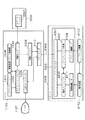
図1は本発明の代表的な実施の形態であるプリンタシステム構成を示すブロック図である。このプリンタシステムはホストコンピュータ(以下、ホストという)1100とプリンタ1000とで構成され、これらが接続ケーブル5000によって互いに接続されている。この実施形態ではプリンタは電子写真方式に従って画像形成を行ないプリント出力するレーザビームプリンタ(LBP)としているが、本発明はこれによって限定されるものではなく、例えば、インクジェット方式、熱転写方式などの記録方式に従ってプリント出力を行なうプリンタでも良いことは言うまでもない。
【0010】
まず、図形、イメージ、文字、表(表計算等を含む)等が混在した文書処理が可能なホスト1100の構成について説明する。
図1において、1107はCRT、1108はCRTを制御するCRT制御部(CRTC)、1109は装置各部の総括的な制御、文書処理、プリンタ制御などを実行するCPU、1110はCPU1109が種々の制御や処理を実行するためのワークエリアや電源処理コマンド格納部(後述)1206等として用いるRAM、1111は制御プログラム、文書処理を実行するアプリケーションプログラム1201、アプリケーションインタフェース(I/F)プログラム1202、印刷モニタプログラム1203、印刷ドライバプログラム1204、CRTコントロールプログラム1205などを格納するROM、1112はキーボードやポインティングデバイスを有する入力部、1113は接続ケーブル5000を介してプリンタ1000との通信制御処理を実行するプリンタインタフェース(I/F)、2000は磁気ディスク、光磁気ディスク、フロッピィディスクなどで構成される大容量の情報保存が可能な外部記憶装置、1114は装置構成要素を互いに接続するシステムバスである。外部記憶装置2000には情報を一時的に格納するスプールファイル2001が設けられている。
【0011】
なお、CPU1109はROM1111に格納された各種のプログラムを読みだしてRAM1110のワークエリアに展開して実行する。従って、各種のプログラムによる機能は、CPU1109によるプログラム読みだし、展開、及び、その実行によって実現される。さらに、図示はしていないが、ROM1111には、キーボード、ポンティングデバイスなどのI/Oデバイスを制御する制御プログラムが格納されている。
【0012】
次に、プリンタ1000の構成について説明する。
図1において、4101はプリンタ各部を制御する制御プログラム、プリンタモニタプログラム4201、プリンタコマンド処理プログラム4202、電源コントロールプログラム4203などを格納するROM、4102は前述のプログラムの実行のためのワークエリアとして用いられるRAM、4103は装置利用者がプリンタ操作のための各種指示の入力やプリンタの状態を表示するための操作パネルである。操作パネル4103には各種指示スイッチなどを有した入力部4105、メッセージ表示を行なうLCD4106、装置動作状態を示すLED4107を備えている。RAM4102は増設ポート(不図示)に接続されるオプションRAMによりメモリ容量の拡張が可能であり、RAM4102には、プリントデータを展開するための出力情報展開領域、環境データ格納領域が設定され、RAM4102の一部はNVRAMとして機能するようになっている。ROM4101には、ホスト1100で利用されるプリンタに固有の情報等も格納される。
【0013】
また、4104はROM4101に記憶された制御プログラム等に基づいて装置各部の総括的な制御を行なうCPU、4108は接続ケーブル5000を介してホスト1100との間で情報の送受信などの通信制御を行なうホストインタフェース(I/F)、4109はプリント機構インタフェース(I/F)、4110は電源装置制御部、4111は電源制御インタフェース(I/F)、4112は装置各部に電源を供給する電源装置、4113はプリント機構(I/F)4109を介して出力される画像信号に基づいてプリント出力を行なうプリント機構(プリンタエンジン)、4114は装置構成要素を互いに接続するシステムバスである。
【0014】
ここで、CPU4104はホストインタフェース(I/F)4108を介してホスト1100との通信が可能であり、プリンタ内の情報等をホスト1100に通知したり、ホスト(I/F)4108を介して通知されるホスト1100からの電源コマンド(詳細は後述)に従って電源装置制御部4110を介してプリント機構4113への電源供給を制御する。
【0015】
また、プリンタ1000は従来技術で説明したような2つの動作モード、即ち、通常モードと省エネルギーモードを有し、これらのモードは、ホスト1100が発行する後述する電源コマンドに従って切り替わる。
図2はプリンタ(LBP)1000の構成を示す側断面図である。LBP1000は、接続ケーブル5000を介して接続されているホスト1100から供給されるプリント情報(文字コード等)やフォーム情報あるいはマクロ命令等を入力して記憶すると共に、それらの情報に従って対応する文字パターンやフォームパターン等を作成し、記録媒体である記録紙に像を形成して出力する。
【0016】
図2において、4103は操作のためのスイッチ、LED、LCD等が配されている操作パネル、1001はLBP1000全体の制御やホストから供給される文字情報等を解析を行なうプリンタ制御ユニットである。プリンタ制御ユニット(プリンタコントローラ)1001は、主に文字情報を対応する文字パターンのビデオ信号に変換してレーザドライバ1002に出力する。図1との対応関係で言うと、プリンタコントローラ1001には、図1に示すプリンタ1000の操作パネル4103、電源装置4112、プリント機構(プリンタエンジン)4113、ホストI/F4108を除く全ての構成要素が含まれている。
【0017】
従って以下に述べる図2の各構成要素において、プリンタコントローラ1001、操作パネル4103、ホストI/F4108以外は全てプリント機構(プリンタエンジン)4113の構成要素となる。
レーザドライバ1002は半導体レーザ1003を駆動するための回路であり、入力されたビデオ信号に応じて半導体レーザ1003から照射されるレーザ光1004のオン/オフを制御する。レーザ光1004は回転多面鏡1005でその照射方向が曲げられて静電ドラム1006上を走査露光する。これにより、静電ドラム1006上には文字パターンの静電潜像が形成される。この潜像は、静電ドラム1006周囲に配設された現像ユニット1007により現像された後、記録紙に転写される。転写された記録紙は搬送ローラ1012〜1013によって定着器1014に搬送され、定着器1014で転写された画像を定着する。その後、記録紙は排出ローラ1015〜1016によって排出トレイ1017に排出される。本実施例では記録紙としてカットシートが用いられている。カットシート記録紙はLBP1000に装着した用紙カセット1008に収納され、給紙ローラ1009および搬送ローラ1010〜1011とにより、装置内に取り込まれて、静電ドラム1006に供給される。
【0018】
LBP1000には、接続ケーブル5000を介してホストとのデータの送受信を行うホストI/F4108が備えられている。
また、LBP1000には、カードスロット(不図示)を少なくとも1個以上備え、内臓フォントに加えてオプションフォントカード、使用言語の異なる制御カード(エミュレーションカード)をそのカードスロットに挿入して使用できるように構成されている。
【0019】
図3は図1で説明したプリンタシステムのソフトウェア構成を示すブロック図である。図3において、既に図1〜図2において説明した構成要素には同じ参照番号を付している。そして、図3では特に、ホスト1100のROM1111やRAM1110に格納或いは設定されたプログラムや領域、プリンタ1000のROM4101に格納されたプログラムの相互関係について、これらのプログラムが実行されたときの動作から説明する。
【0020】
まず、ホスト1100側における動作について述べる。
アプリケーションプログラム1201の実行によって文書処理がなされると、アプリケーションI/Fプログラム1202は、その文書処理によって発生したプリントデータをアプリケーションプログラム1201から受取り、これを印刷コマンドに変換して印刷モニタプログラム1203に受け渡す。印刷モニタプログラム1203では受け取った印刷コマンドをスプールファイル2001に出力する。その後、印刷モニタプログラム1203は、スプールファイル2001に出力した所定単位の印刷コマンド群をアプリケーションプログラム1201が発行した命令に基づいて読みだし、これを印刷ドライバプログラム1204に渡す。
【0021】
印刷ドライバプログラム1204は、印刷モニタプログラム1203から渡された印刷コマンドをプリンタI/F1113に出力する。また、印刷ドライバプログラム1204は、プリンタI/F1113を介してプリンタ1000からの情報を取得する。プリンタI/F1113は、印刷ドライバプログラム1204から出力された印刷コマンドを接続ケーブル5000を介して、プリンタコマンド処理部4202に転送する。
【0022】
さて、CRTコントロールプログラム1205は、プリンタI/F1113からのプリンタ電源コマンドを取得して、そのコマンドに基づく情報をCRT1107に表示するよう制御する。電源処理コマンド格納部1206は後述するフォーマットをもつ電源コマンドを格納する。このコマンドはアプリケーション1201の実行により生成されるコマンドである。
【0023】
次に、プリンタ1000の動作について述べる。
プリンタモニタ4201は、接続ケーブル5000を介してプリンタI/F1113との間のデータ送受信の制御を行なうとともに、プリンタの総括的な制御と後述する各プログラムにホスト1100からの情報を転送して、それらの実行制御を行なう。
【0024】
プリンタコマンド処理プログラム4202は、プリンタI/F1113から転送された印刷コマンドを処理してプリント機構I/F4109に出力する。プリント機構I/F4109は、プリンタコマンド処理部4202からの出力結果をプリント機構4113に出力する。これによって、プリント機構(プリンタエンジン)4113はプリント機構I/F4109からの出力に基づいて画像形成と印刷出力を実行する。
【0025】
電源コントロールプログラム4203は、ホスト1100から転送された電源コマンドを解析し、その解析結果に基づいて、電源装置制御部4110を制御する。その結果、電源制御I/F4111を介して、電源装置制御部4110は電源コマンドに従って電源装置4112からプリント機構への電源供給を制御することになる。例えば、省エネルギモードで動作するときには、プリント機構(プリンタエンジン)4113の消費電力の大きい可動部(レーザドライバ、搬送ローラ、給紙ローラ、静電ドラム、定着器等)への電力供給は全て停止される。
【0026】
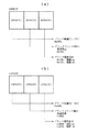
図4は電源コマンドのフォーマットを示す図である。ここで、図4(a)は省エネルギモードで動作するようプリンタに指示するコマンド“DPROT”に関するコマンドフォーマットを、図4(b)は通常モードで動作するようプリンタに指示するコマンド“UPROT”に関するコマンドフォーマットを示している。
【0027】
図4に示されるように、どちらのコマンドも同じコマンド構成をもつ、即ち、3つの共通オペランドより構成されている。これら3つのオペランドは各々、16ビットの長さをもち、第1オペランド(DPROT1、UPROT1)にはプリンタ制御コマンドであることを示す識別子(ID)がセットされ、第2オペランド(DPROT2、UPROT2)にはその制御が電源関連であることを示すプリンタコマンド種別の識別子がセットされ、第3オペランド(DPROT3、UPROT3)には更に詳細な命令であることを示す識別子(ここではプリンタ電源命令)がセットされる。
【0028】
次に、ホストからプリンタの電源を制御する処理の内、プリンタ側の処理について、図5に示すフローチャートを参照して説明する。これによって、ホストから随時プリンタの電源装置を制御することが可能になる。図5に示す処理はプリンタモニタ4201、プリンタコマンド処理プログラム4202、電源コントロールプログラム4203が協働して実行される。
【0029】
まず、ステップS1ではホスト1100からのコマンドを受信し、さらに、ステップS2ではその受信コマンドが図5に示した電源コマンドであるか否かを調べる。ここで、そのコマンドが電源コマンド以外のコマンドであれば処理はステップS3に進み、そのコマンドに応じた処理を実行する。これに対して、受信コマンドが電源コマンドであれば、処理はステップS4に進み、その電源コマンドを電源コントロールプログラムに転送する。以上の処理で、ステップS1はプリンタモニタ4201によって、ステップS2とステップS4とはプリンタコマンド処理プログラム4202で実行される。
【0030】
さて、ステップS5では、受信電源コマンドが、“通常モードコマンド”であるか、或いは、“省エネルギモードコマンド”であるかを判別する。ここで、その電源コマンドが“通常モードコマンド”であれば処理はステップS7に進み、“省エネルギモードコマンド”であれば処理はステップS11に進む。
ステップS7では、プリンタ1000が現在“通常モード”で動作しているかどうかを調べ、その動作モードが“通常モード”であれば、その後処理は何もせずに終了するが、その動作モードが“通常モード”でなければ、処理はステップS8に進み、電源制御I/F4111を介して電源装置4112が“通常モード”で動作するよう制御する。
【0031】
一方、ステップS11では、プリンタ1000が現在“省エネルギモード”で動作しているかどうかを調べ、その動作モードが“省エネルギモード”であれば、その後処理は何もせずに終了するが、その動作モードが“省エネルギーモード”でなければ、処理はステップS12に進み、電源制御I/F4111を介して電源装置4112が“省エネルギモード”で動作するよう制御する。
【0032】
以上の処理によって、ホストは適宜プリンタの動作モードを切り換えることができる。
次に、ホストからプリンタの電源を制御する処理の内、ホスト側の処理について、図6に示すフローチャートを参照して説明する。これによって、ホストは印刷するプリントデータの送信を契機としてプリンタの電源装置を制御することが可能になる。図6に示す処理は印刷モニタプログラム1203、印刷ドライバプログラム1204が協働して実行される。
【0033】
まず、ステップS13では印刷モニタプログラム1203からスプールファイル2001へプリントデータが入力される。次に、ステップS14では、印刷ドライバプログラム1204はプリンタ1000のその時点での動作モードをプリンタ1000より取得し、そのモードが“通常モード”であるかどうか調べる。ここで、そのモードが“通常モード”であれば、処理はステップS16に進むが、“通常モード”でなければ処理はステップS15に進み、印刷モニタープログラム1203は印刷ドライバプログラム1204を介して電源コマンド“UPROT”をプリンタ1000に送信する。
【0034】
最後に、ステップS16ではプリントデータをスプールファイル2001から読みだしてプリンタ1000に転送する。
以上の処理によって、プリントデータのスプールファイル2001への出力を印刷するプリントデータのプリンタへの送信の契機として、プリンタは省エネルギーモードの動作から通常モードの動作に切り換わる。
【0035】
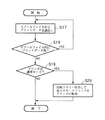
さらに別のホスト側の処理について、図7に示すフローチャートを参照して説明する。これによって、スプールファイル2001内のプリントデータの有無を判別し、その判別結果に従って、プリンタの電源装置を制御することが可能になる。図7に示す処理も印刷モニタプログラム1203、印刷ドライバプログラム1204が協働して実行される。
【0036】
まず、ステップS17では印刷モニタプログラム1203はスプールファイル2001からプリントデータを読み出して印刷ドライバプログラム1204を介してプリンタ1000にこれを送信するとともに、さらに、ステップS18ではスプールファイル2001にプリントデータが残存しているかどうかを調べ、データが残存していれば処理はステップS17に戻り、データがスプールファイル2001に残存していないことが判別されれば処理はステップS19に進む。印刷ドライバプログラム1204はプリンタ1000のその時点での動作モードをプリンタ1000より取得し、そのモードが“通常モード”であるかどうか調べる。ここで、そのモードが“通常モード”でなければ、処理を終了するが、“通常モード”であれば処理はステップS20に進み、印刷モニタプログラム1203は印刷ドライバプログラム1204を介して電源コマンド“DPROT”をプリンタ1000に送信する。
【0037】
以上の処理によって、スプールファイル2000に送信すべきプリントデータがなくなった時点で、プリンタ1000の動作モードを調べ、その動作モードが“通常モード”であれば、プリンタ1000の動作モードを“省エネルギモードに切り換える。
以上説明した制御によれば、図6〜図7の処理を連続的に実行することにより、プリンタ1000の動作モードに係わらず、送信すべきプリントデータがホスト側に存在するときのみにプリンタの動作モードを“通常モード”に設定することができ、そのプリントデータがホスト側になくなればプリンタの動作モードを“省エネルギモード”に切り換えるよう制御することができる。
【0038】
一方、プリンタ側ではホスト側より送られてくる電源コマンドによってその動作モードが随時切り替わるので、ホストとプリンタとがシステムとして協働することにより、実際のプリント動作が発生する以外のときにはプリンタの消費電力を削減することができる。
尚、本発明は、複数の機器から構成されるシステムに適用しても良いし、1つの機器から成る装置に適用しても良い。また、本発明はシステム或は装置にプログラムを供給することによって達成される場合にも適用できることはいうまでもない。この場合、本発明に係わるプログラムを格納した記憶媒体が、本発明を構成することになる。そして、該記憶媒体から、そのプログラムをシステム或は装置に読み出すことによって、そのシステム或は装置が、予め定められた仕方で動作する。
【0039】
【発明の効果】
以上説明してきたように本発明によれば、印刷コマンドのスプール開始後、且つ、プリンタへの転送前に、そのプリンタの電源供給モードがリモート制御されるので、プリンタのプリント出力に適切な電力が供給されるという効果がある。これによって、プリント出力を考慮した電源制御によってより効果的に消費電力を削減できる。
【図面の簡単な説明】
【図1】本発明の代表的な実施の形態であるプリンタシステム構成を示すブロック図である。
【図2】プリンタ(LBP)1000の構成を示す側断面図である。
【図3】図1で説明したプリンタシステムのソフトウェア構成を示すブロック図である。
【図4】電源コマンドのフォーマットを示す図である。
【図5】電源制御に係わるプリンタ側の処理を示すフローチャートである。
【図6】電源制御に係わるホスト側の処理を示すフローチャートである。
【図7】電源制御に係わるホスト側の処理を示すフローチャートである。
【符号の説明】
1000 プリンタ
1100 ホスト
1107 CRT
1108 CRTC
1109、4104 CPU
1110、4102 RAM
1111、4101 ROM
1112、4105 入力部
1113 プリンタインタフェース(I/F)
1114、4114 システムバス
1201 アプリケーションプログラム
1202 アプリケーションI/Fプログラム
1203 印刷モニタプログラム
1204 印刷ドライバプログラム
1205 CRTコントロールプログラム
2000 外部記憶装置
2001 スプールファイル
4103 操作パネル
4106 LCD
4107 LED
4108 ホストインタフェース(I/F)
4109 プリント機構インタフェース(I/F)
4110 電源装置制御部
4111 電源制御インタフェース(I/F)
4112 電源装置
4113 プリント機構
4201 プリンタモニタプログラム
4202 プリンタコマンド処理プログラム
4203 電源コントロールプログラム
5000 接続ケーブル[0001]
TECHNICAL FIELD OF THE INVENTION
The present invention relates to an information processing apparatus and an information processing method thereof.
[0002]
[Prior art]
In a conventional printer system including a host computer (hereinafter, referred to as a host) and a printer, the power supply control of the printer from the host uses one of two operation modes, an energy saving mode and a normal mode. Was selected and specified, and was executed according to the selected mode. In this case, when the energy saving mode is selected, measures have been taken to reduce power consumption unless the printer has been used for a certain period of time. Further, even when the normal mode is selected, the mode is automatically switched to the energy saving mode if print data is not input to the printer for a certain period of time.
[0003]
[Problems to be solved by the invention]
However, in the above conventional example, there are only two modes for power control (that is, whether or not to use the energy saving mode). For example, even when the operation of the system is not inconvenient in the energy saving mode, the normal mode is selected. There is a problem in that the system operates and power is supplied to a printer that is not actually used, thereby saving power consumption.
[0004]
The present invention has been made in view of the above conventional example, and an object of the present invention is to provide an information processing apparatus and an information processing method capable of more effectively reducing power consumption.
[0005]
[Means for Solving the Problems]
In order to achieve the above object, an information processing apparatus according to the present invention has the following configuration.
That is, an information processing apparatus capable of communicating with a printer, generating a print command that can be processed by the printer, and executing an application program for executing document processing, and converting data from the application program into a print command. Converting means for converting the print command converted by the converting means into a spool, and starting output of a spool of a print command obtained by converting data from the application program; and Instruction transfer means for instructing remote control of the power supply mode of the printer before transfer to the printer, and control to transfer the converted print command output and spooled via the output means to the printer. Output control means for controlling the Includes an information processing apparatus for, characterized in that by the processing based on the print command transferred print output is performed.
According to another aspect of the present invention, there is provided an information processing method for an information processing apparatus capable of communicating with a printer, generating a print command that can be processed by the printer, and executing an application program for executing document processing. A conversion step of converting data from the application program into a print command; a spooling step of spooling the print command converted in the conversion step; and a start of spooling of a print command obtained by converting the data from the application program. And before the transfer to the printer, an instruction control step of causing the printer to instruct the printer to remotely control the power supply mode of the printer, and the conversion spooled in the spooling step. Transfer the print command to the printer. And a transfer control step of controlling to, in said printer includes an information processing method for, characterized in that by the processing based on the print command transferred print output is performed.
[0006]
BEST MODE FOR CARRYING OUT THE INVENTION
With the configuration described above, the present invention provides a printer system having a host that generates print data and a printer that has a first operation mode that consumes a large amount of power and a second operation mode that consumes a small amount of power. Determines the presence or absence of print data generated by the printer, and controls the instruction means for giving an instruction to the printer so as to set the operation mode of the printer to the first or second mode according to the determination result. Set the operation mode according to the instruction.
[0007]
Here, the host is provided with a storage unit for temporarily storing the print data, and when the input of the print data into the storage unit is a trigger for recognizing that the print data exists, the print data no longer remains in the storage unit. The time is an opportunity to recognize that print data does not exist.
The host sets the operation mode of the printer to the first mode when it recognizes that print data exists, and sets the operation mode of the printer to the second mode when it recognizes that print data does not exist. Control to do.
[0008]
On the other hand, the printer includes a receiving unit that receives print data and an instruction for setting an operation mode, an image forming unit that forms an image based on the received print data, and prints out the image, and a power supply to the image forming unit. Power supply control means for controlling the supply.
Then, the power supply control unit controls the power supply to the image forming unit according to the first or second operation mode.
[0009]
Hereinafter, preferred embodiments of the present invention will be described in detail with reference to the accompanying drawings.
FIG. 1 is a block diagram showing the configuration of a printer system according to a typical embodiment of the present invention. This printer system includes a host computer (hereinafter, referred to as a host) 1100 and a
[0010]
First, the configuration of the
In FIG. 1,
[0011]
Note that the
[0012]
Next, the configuration of the
In FIG. 1,
[0013]
[0014]
Here, the
[0015]
The
FIG. 2 is a side sectional view showing the configuration of the printer (LBP) 1000. The
[0016]
In FIG. 2,
[0017]
Therefore, among the components shown in FIG. 2 described below, all except the
The
[0018]
The
The
[0019]
FIG. 3 is a block diagram showing a software configuration of the printer system described in FIG. In FIG. 3, the components already described in FIGS. 1 and 2 are denoted by the same reference numerals. In FIG. 3, the interrelationship between programs and areas stored or set in the
[0020]
First, the operation on the
When the document processing is performed by executing the
[0021]
The
[0022]
The
[0023]
Next, the operation of the
The
[0024]
The printer
[0025]
The power
[0026]
FIG. 4 is a diagram showing the format of the power command. Here, FIG. 4A shows a command format relating to a command "DPROT" instructing the printer to operate in the energy saving mode, and FIG. 4B shows a command format relating to a command "UPROT" instructing the printer to operate in the normal mode. Shows the command format.
[0027]
As shown in FIG. 4, both commands have the same command configuration, that is, are composed of three common operands. Each of these three operands has a length of 16 bits, an identifier (ID) indicating a printer control command is set in the first operand (DPROT1, UPROT1), and the second operand (DPROT2, UPROT2) is set in the second operand (DPROT2, UPROT2). Is set with an identifier of a printer command type indicating that the control is related to the power supply, and an identifier (here, a printer power supply instruction) indicating a more detailed instruction is set in the third operand (DPROT3, UPROT3). You.
[0028]
Next, among the processing for controlling the power supply of the printer from the host, the processing on the printer side will be described with reference to the flowchart shown in FIG. This allows the host to control the power supply of the printer at any time. The processing shown in FIG. 5 is executed by the
[0029]
First, in step S1, a command from the
[0030]
In step S5, it is determined whether the received power command is a “normal mode command” or an “energy saving mode command”. If the power command is a "normal mode command", the process proceeds to step S7. If the power command is a "energy saving mode command", the process proceeds to step S11.
In step S7, it is checked whether or not the
[0031]
On the other hand, in step S11, it is determined whether or not the
[0032]
Through the above processing, the host can appropriately switch the operation mode of the printer.
Next, of the processing for controlling the power supply of the printer from the host, the processing on the host side will be described with reference to the flowchart shown in FIG. This enables the host to control the power supply of the printer upon transmission of print data to be printed. The process shown in FIG. 6 is executed by the
[0033]
First, in step S13, print data is input from the
[0034]
Finally, in step S16, the print data is read from the
Through the above processing, the printer switches from the operation in the energy saving mode to the operation in the normal mode as a trigger for transmitting the print data for printing the output of the print data to the
[0035]
Still another host-side process will be described with reference to the flowchart shown in FIG. This makes it possible to determine the presence or absence of print data in the
[0036]
First, in step S17, the
[0037]
When there is no more print data to be transmitted to the
According to the control described above, the processing of FIGS. 6 and 7 is continuously performed, so that the operation of the printer is performed only when print data to be transmitted exists on the host side regardless of the operation mode of the
[0038]
On the other hand, the operation mode of the printer is switched at any time by a power command sent from the host, so that the host and the printer cooperate as a system so that the power consumption of the printer can be reduced except when an actual printing operation occurs. Can be reduced.
The present invention may be applied to a system including a plurality of devices, or may be applied to an apparatus including a single device. Needless to say, the present invention can be applied to a case where the present invention is achieved by supplying a program to a system or an apparatus. In this case, the storage medium storing the program according to the present invention constitutes the present invention. Then, by reading the program from the storage medium to a system or an apparatus, the system or the apparatus operates in a predetermined manner.
[0039]
【The invention's effect】
As described above, according to the present invention, the power supply mode of the printer is remotely controlled after the spooling of the print command is started and before the print command is transferred to the printer. It has the effect of being supplied. As a result, power consumption can be more effectively reduced by power control taking print output into consideration.
[Brief description of the drawings]
FIG. 1 is a block diagram illustrating a configuration of a printer system according to a typical embodiment of the present invention.
FIG. 2 is a side sectional view showing a configuration of a printer (LBP) 1000.
FIG. 3 is a block diagram illustrating a software configuration of the printer system illustrated in FIG. 1;
FIG. 4 is a diagram showing a format of a power command.
FIG. 5 is a flowchart illustrating processing on the printer side related to power control.
FIG. 6 is a flowchart showing processing on the host side relating to power control.
FIG. 7 is a flowchart illustrating processing on the host side relating to power control.
[Explanation of symbols]
1000 Printer
1100 host
1107 CRT
1108 CRTC
1109, 4104 CPU
1110, 4102 RAM
1111 and 4101 ROM
1112, 4105 Input unit
1113 Printer interface (I / F)
1114, 4114 System bus
1201 Application program
1202 Application I / F program
1203 Print monitor program
1204 Print driver program
1205 CRT control program
2000 External storage device
2001 Spool file
4103 Operation panel
4106 LCD
4107 LED
4108 Host interface (I / F)
4109 Print mechanism interface (I / F)
4110 Power supply control unit
4111 Power supply control interface (I / F)
4112 Power supply
4113 Printing mechanism
4201 Printer monitor program
4202 Printer command processing program
4203 Power control program
5000 Connection cable
Claims (4)
前記アプリケーションプログラムからのデータを印刷コマンドに変換する変換手段と、
前記変換手段により変換された印刷コマンドをスプールするべく出力させる手段と、
前記アプリケーションプログラムからのデータを変換して得られた印刷コマンドのスプールの出力開始の後、且つ、前記プリンタへの転送前に、前記プリンタの電源供給モードをリモート制御させるべく指示する指示制御手段と、
前記出力させる手段を介して出力されスプールされた前記変換された印刷コマンドを前記プリンタに転送するよう制御する出力制御手段とを有し、
前記プリンタにおいては、転送されてきた前記印刷コマンドに基づく処理をしてプリント出力が実行されることを特徴する情報処理装置。An information processing apparatus capable of communicating with a printer, generating a print command that can be processed by the printer , and executing an application program for executing document processing ,
Conversion means for converting the data from the application program into print command,
And means for outputting to spool the converted print command by said converting means,
Instruction control means for instructing to remotely control the power supply mode of the printer after the start of spool output of a print command obtained by converting data from the application program and before transfer to the printer; ,
Output control means for controlling the transfer of the spooled converted print command output and spooled through the output means to the printer,
An information processing apparatus, wherein the printer performs a process based on the transferred print command and executes print output.
前記指示制御手段は、前記出力制御手段によりスプールされた印刷コマンドを前記プリンタに転送させる前に、前記調べる手段により調べられた前記プリンタの電源状態に基づき、前記プリンタの電源供給モードを制御させるべく指示することを特徴とする請求項1に記載の情報処理装置。Further comprising means for checking the power state of the printer,
The instruction control means controls the power supply mode of the printer based on the power state of the printer checked by the checking means before transferring the print command spooled by the output control means to the printer. The information processing apparatus according to claim 1, wherein the instruction is given.
前記指示制御手段は、前記判別手段によって前記プリンタに転送すべき印刷コマンドが残存していないとされた場合に、前記プリンタの各部への電源供給を節約するモードへ移行する指示をすることを特徴とする請求項1又は2に記載の情報処理装置。A determination unit configured to determine that no print command to be transferred to the printer remains in the spool file spooled by the output unit;
The instruction control unit instructs, when the determination unit determines that there is no print command to be transferred to the printer, a transition to a mode for saving power supply to each unit of the printer. The information processing apparatus according to claim 1.
前記アプリケーションプログラムからのデータを印刷コマンドに変換する変換工程と、
前記変換工程において変換された印刷コマンドをスプールするスプーリング工程と、
前記アプリケーションプログラムからのデータを変換して得られた印刷コマンドのスプール開始の後、且つ、前記プリンタへの転送前に、前記プリンタの電源供給モードをリモート制御させるべく前記プリンタへの指示を行なわせるようにする指示制御工程と、
前記スプーリング工程においてスプールされた前記変換された印刷コマンドを前記プリンタに転送させるべく制御する転送制御工程とを有し、
前記プリンタにおいては、転送されてきた前記印刷コマンドに基づく処理をしてプリント出力が実行されることを特徴する情報処理方法。An information processing method of an information processing apparatus capable of communicating with a printer, generating a print command processable by the printer , and executing an application program for executing document processing ,
A conversion step of converting data from the application program into print command,
A spooling step of spooling the print command converted in the conversion step,
After the spooling of the print command obtained by converting the data from the application program is started and before the print command is transferred to the printer, an instruction is given to the printer to remotely control the power supply mode of the printer. Instruction control step to be performed,
A transfer control step of controlling to transfer the converted print command spooled in the spooling step to the printer,
An information processing method, wherein the printer performs a process based on the transferred print command and executes print output.
Priority Applications (1)
| Application Number | Priority Date | Filing Date | Title |
|---|---|---|---|
| JP18923595A JP3559620B2 (en) | 1995-07-25 | 1995-07-25 | Printer system |
Applications Claiming Priority (1)
| Application Number | Priority Date | Filing Date | Title |
|---|---|---|---|
| JP18923595A JP3559620B2 (en) | 1995-07-25 | 1995-07-25 | Printer system |
Publications (2)
| Publication Number | Publication Date |
|---|---|
| JPH0944324A JPH0944324A (en) | 1997-02-14 |
| JP3559620B2 true JP3559620B2 (en) | 2004-09-02 |
Family
ID=16237873
Family Applications (1)
| Application Number | Title | Priority Date | Filing Date |
|---|---|---|---|
| JP18923595A Expired - Fee Related JP3559620B2 (en) | 1995-07-25 | 1995-07-25 | Printer system |
Country Status (1)
| Country | Link |
|---|---|
| JP (1) | JP3559620B2 (en) |
Families Citing this family (3)
| Publication number | Priority date | Publication date | Assignee | Title |
|---|---|---|---|---|
| JP3495242B2 (en) | 1998-02-06 | 2004-02-09 | 富士通株式会社 | Information processing apparatus, mode control method, and storage medium |
| JP3565180B2 (en) * | 2001-03-30 | 2004-09-15 | ミノルタ株式会社 | Network printing system, service agent server, and program |
| JP6132535B2 (en) * | 2012-12-07 | 2017-05-24 | キヤノン株式会社 | Printing system, printing control apparatus, printing control apparatus control method, and program |
-
1995
- 1995-07-25 JP JP18923595A patent/JP3559620B2/en not_active Expired - Fee Related
Also Published As
| Publication number | Publication date |
|---|---|
| JPH0944324A (en) | 1997-02-14 |
Similar Documents
| Publication | Publication Date | Title |
|---|---|---|
| US6459496B1 (en) | Information processing apparatus indicating a sleep state and a ready state of printing apparatuses | |
| JP3634447B2 (en) | Image processing apparatus and method | |
| US6700677B1 (en) | Printing apparatus, data output apparatus and computer readable memory medium | |
| JP3559620B2 (en) | Printer system | |
| JP3123634B2 (en) | Printing apparatus and control method thereof | |
| JPH08101606A (en) | Printing device | |
| JP3181779B2 (en) | Printing apparatus, interface apparatus, information processing apparatus, and control method | |
| JP2004017389A (en) | Information processor and printer | |
| JPH08282064A (en) | Recording apparatus and recording control method | |
| JP3209857B2 (en) | PRINTING SYSTEM, PRINTING DEVICE, DATA DISTRIBUTION DEVICE, PRINTING SYSTEM CONTROL METHOD, PRINTING DEVICE CONTROL METHOD, AND DATA DISTRIBUTION DEVICE CONTROL METHOD | |
| JP2000318272A (en) | Printer, print mode control method and memory medium | |
| JP3209858B2 (en) | Print control device and print control method | |
| JPH09231027A (en) | Information processor, printer, print system and data processing method for print system | |
| JP3222675B2 (en) | Printing apparatus and display control method for printing apparatus | |
| JP2000079742A (en) | Printing apparatus, print method, printing system and memory medium | |
| JPH09191568A (en) | Output device and power supply control thereof | |
| JP3327686B2 (en) | Output device and output method | |
| JPH11194917A (en) | Printing system | |
| JPH1199730A (en) | Printer and its control method | |
| JPH11203067A (en) | Printer control system, printer, host computer, printing method and storage medium | |
| JPH09179700A (en) | Printer, printing device, printing system, and information processor | |
| JP2005205829A (en) | Printing control device | |
| JP2003330651A (en) | Output device and output method | |
| JP2002052790A (en) | Imaging apparatus and method | |
| JPH09218755A (en) | Printing controller and method for processing data of the same |
Legal Events
| Date | Code | Title | Description |
|---|---|---|---|
| TRDD | Decision of grant or rejection written | ||
| A01 | Written decision to grant a patent or to grant a registration (utility model) |
Free format text: JAPANESE INTERMEDIATE CODE: A01 Effective date: 20040517 |
|
| A61 | First payment of annual fees (during grant procedure) |
Free format text: JAPANESE INTERMEDIATE CODE: A61 Effective date: 20040524 |
|
| R150 | Certificate of patent or registration of utility model |
Free format text: JAPANESE INTERMEDIATE CODE: R150 |
|
| FPAY | Renewal fee payment (event date is renewal date of database) |
Free format text: PAYMENT UNTIL: 20090528 Year of fee payment: 5 |
|
| FPAY | Renewal fee payment (event date is renewal date of database) |
Free format text: PAYMENT UNTIL: 20100528 Year of fee payment: 6 |
|
| FPAY | Renewal fee payment (event date is renewal date of database) |
Free format text: PAYMENT UNTIL: 20100528 Year of fee payment: 6 |
|
| FPAY | Renewal fee payment (event date is renewal date of database) |
Free format text: PAYMENT UNTIL: 20110528 Year of fee payment: 7 |
|
| LAPS | Cancellation because of no payment of annual fees |