JP3558091B2 - Play chair - Google Patents
Play chair Download PDFInfo
- Publication number
- JP3558091B2 JP3558091B2 JP17727092A JP17727092A JP3558091B2 JP 3558091 B2 JP3558091 B2 JP 3558091B2 JP 17727092 A JP17727092 A JP 17727092A JP 17727092 A JP17727092 A JP 17727092A JP 3558091 B2 JP3558091 B2 JP 3558091B2
- Authority
- JP
- Japan
- Prior art keywords
- chair
- gaming
- gaming chair
- seat
- slide base
- Prior art date
- Legal status (The legal status is an assumption and is not a legal conclusion. Google has not performed a legal analysis and makes no representation as to the accuracy of the status listed.)
- Expired - Fee Related
Links
Images


Landscapes
- Pinball Game Machines (AREA)
Description
【0001】
【産業上の利用分野】
本発明は、パチンコ遊技場の遊技機毎に対応して島台に設置される遊技用椅子に関するものである。
【0002】
【従来の技術】
従来、パチンコ遊技場に設置される遊技用椅子は、島台に設置される遊技機毎に対応して設けられ、遊技用椅子の設置方法を大別すると、遊技機と所定間隔を空けて遊技用椅子の支柱を床面に固定する固定式と、単に床面に遊技用椅子を載置する載置式の2つの方法がある。
【0003】
【発明が解決しようとする課題】
しかしながら、固定式の遊技用椅子では、大型設備機器等の搬入作業、遊技機の交換作業、島台内部の日常保守点検作業、及び床面の清掃作業において、遊技用椅子が邪魔となって各種作業がしずらく作業能率が上がらないという問題点がある。また、載置式の遊技用椅子では、営業中において、遊技者の故意又は過失により椅子が散乱し美観上好ましくなく、従業員は常時遊技用椅子の整頓作業に気を配らなければならず、また、閉店後においては全ての遊技用椅子の整頓作業をしなければならない。
【0004】
本発明は、上記した事情に鑑みなされたもので、その目的とするところは、遊技用椅子を必要に応じて適切な位置に移動させることにより、遊技場における各種作業能率の向上を図る遊技用椅子を提供することにある。
【0005】
【課題を解決するための手段】
上記した目的を達成するため、請求項1の発明は、各遊技機毎に対応して島台に設置される遊技用椅子において、前記遊技用椅子は、遊技者が着席する座席部と、該座席部裏面に固着されて垂下される垂下部と、該垂下部の下端から床面と平行となるように連続し且つその底面に設けられる車輪によってスライド移動するスライド基部と、からなり、前記島台の下部には、前記座席部を遊技者が遊技を行う時に使用する使用位置と前記座席部を使用位置よりも遊技機側に寄せた収納位置との間で前記スライド基部をスライド形態にて案内するガイド部材を内蔵すると共に、島台の長手方向下部に設けられる巾木に遊技用椅子の配置位置に対応して凹部が形成され、前記垂下部は、その下方が前記収納位置で前記凹部に嵌合されるように水平から下方に向かって屈曲して形成されて前記スライド基部の一端と連結されていることを特徴とするものである。
【0006】
また、請求項2の発明は、請求項1に記載の遊技用椅子であって、前記ガイド部材には、前記スライド基部が使用位置と収納位置とでそれぞれ移動しないように固定する固定機構を設けたことを特徴とするものである。
【0007】
また、請求項3の発明は、請求項2に記載の遊技用椅子であって、前記固定機構は、前記スライド基部が固定される位置に達すると自動的に固定し、この固定状態を解除する操作レバーを設けたことを特徴とするものである。
【0008】
また、請求項4の発明は、請求項3に記載の前記操作レバーを遊技用椅子の背面側に設けたことを特徴とするものである。
【0009】
【実施例】
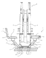
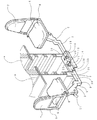
以下、図面を参照して本発明の実施例について説明する。図1は、島台B内部を表す断面概略図であり、図2は、遊技用椅子1周辺の島台B内部を表す一部破断斜視図であり、図3は、ピストン部3の内部構造を表す断面概略図であり、図4は遊技用椅子1の収納状態を表す平面図であり、図5は、島台B全体を表す斜視図である。
【0010】
図1に示すように島台Bは、高さ方向の中段に複数のパチンコ機Aが背向列設され、そのパチンコ機A毎に対応して遊技用椅子1が設置されている。遊技用椅子1は、遊技者が着席する本発明の座席部に相当する座部6と、座席部を支持する本発明の垂下部に相当する支柱腕2と、本発明のスライド基部に相当するピストン部3と、座部6を遊技者が遊技を行う時に使用する使用位置(図1の左側に示す遊技用椅子1)と座部6を使用位置よりもパチンコ機A側に寄せた収納位置(図1の右側に示す遊技用椅子1)との間でピストン部3をスライド形態にて案内する本発明のガイド部材に相当する収納枠12と、遊技用椅子1が使用位置と収納位置で移動しないように固定する本発明の固定機構に相当するローラー錠23,前停止孔14,後停止孔15と、ローラー錠23,前停止孔14,後停止孔15による固定状態を解除する本発明の操作レバーに相当するペタル21とで構成されている。
【0011】
まず、遊技者が着席する座部6は、支柱腕2に回転自在で軸着され、座部6の一端には蝶番部8を介して背部7が連結されており、背部7は蝶番部8によって略垂直状態(図1の左側に示す遊技用椅子1)と略水平状態(図1の右側に示す遊技用椅子1)とに折り畳み可能になっている。
【0012】
次に、座部6を支持する支柱腕2は、内部が中空状に形成され、上端は座部6の裏面中心の取付部(図示省略)に軸着され、下端はピストン部3の一端と連結部9で着脱自在に嵌合されるようになっており、全体的には座部6に軸着されて垂下されるようになっている。また、図1及び図2に示すように、支柱腕2下方の形状は、遊技用椅子1の収納位置で島台B巾木30に形成される凹部31に嵌合されるように逆L字状で形成されている。また、支柱腕2は、上端から下端にかけて島台Bに向かって湾曲する湾曲状となっており、図1に示すように背面側にペタル21が装設されている。
【0013】
このような形状により、遊技用椅子1が使用位置にある場合には、座部6下方に遊空間ができ、遊空間に玉箱を置いたりすることができる。また、遊技用椅子1が収納位置にある場合には、巾木30の平面と支柱腕2下方の平面4とが略同一平面となって、支柱腕2が島台Bにほぼ当接した状態で座部6下方に遊空間ができるになっている。よって、巾木30周辺まで清掃具を往来させることが可能となり、大型清掃機械や清掃具による床面磨き作業が行い易くその作業能率が向上し、また、パチンコ機Aの交換作業、島台B内部の日常保守点検作業においては、島台Bに近づいた状態で作業を行うことができるため、その作業能率が向上する。
【0014】
また、ペタル21が支柱腕21の背面側に装設されており、遊技者が遊技用椅子1に座った状態ではペタル21が操作しづらいようになっている。このため、遊技者が座った状態での故意又は過失による不用意な遊技用椅子1の移動を防止して遊技者の安全を確保し、また、収納位置にある遊技用椅子1の操作レバーの操作を容易に行うことができる。
【0015】
次に、支柱腕2と連結部9で嵌合するピストン部3は、内部が中空状に形成され、全体が床面と平行となるように連続し且つ床面と当接するように略直方体で形成され、底面側にはピストン部3をスライド形態にてスライドさせるための車輪5,5Aが前後に配置されている。ピストン部3の上面は遊技者の足が引っかかりにくいように蒲鉾状になっている。また、ピストン部3は、ペタル21の操作により上面の開口から突出した状態と陥没した状態とに変位するローラー錠23を備えている。
【0016】
このローラー錠23は、ピストン部3に内設する板バネ24に装着され、板バネ24は基部がピストン部3の底面内側に固定され、揺動部にはワイヤー22が係止されている。ワイヤー22は、板バネ24の揺動部からワイヤーの引張方向を変更するホイール32を介して支柱腕2のぺタル21と一体的な伸長梃26に係止され、支柱腕2とピストン部3の内部に張架されている。
【0017】
このような構造により、ペタル21未操作時には、板バネ24の弾性力でローラー錠23が突出した状態(図3の点線状態)を維持し、ペタル21操作時には、伸長梃26がワイヤを介して板バネ24の揺動部を引き下げ、板バネ24の弾性力に抗してローラー錠23が陥没した状態(図3の実線状態)となるようになっている。
【0018】
次に、図2を参照して上述したピストン部3を案内すると共に、上述したローラー錠23を係止してピストン部3の移動を固定する収納枠12について説明する。1つの収納枠12は、背向するパチンコ機Aに対して設けられる2つの遊技用椅子1のピストン部3が島台B長手方向に対して直角方向で互いに反対方向から挿入可能な2つの収納部12A,12Bが形成されている。収納部12A,12Bの上面には、上述したローラー錠23を係止するための前停止孔14、後停止孔15がそれぞれに開口形成されている。この前停止孔14,後停止孔15の開口位置は、遊技用椅子1の使用位置と収納位置に対応して形成されている。
【0019】
次に、遊技用椅子1の移動方法について説明する。遊技用椅子1は、使用位置と収納位置との間で移動可能でそれぞれの位置で固定されるようになっている。使用位置にある遊技用椅子1は、ローラー錠23が前停止孔14に係止されていることにより固定されており、収納位置にある遊技用椅子1は、ローラー錠23が後停止孔15に係止されていることにより固定されている。それぞれの固定状態は、ペタル21を押下すると、ワイヤ22を介してローラー錠23が陥没してローラー錠23が前停止孔14又は後停止孔15と係止されなくなり、遊技用椅子1が移動可能となる。そして、遊技用椅子1を使用位置と収納位置との間で移動している時には、ローラー錠23が板バネ24の弾性力で常時上方へ付勢されているため収納枠12上面内側に摺動しながら移動し、ローラー錠23が前停止孔14又は後停止孔15に到達すると、板バネ24の弾性力でローラー錠23が前停止孔14又は後停止孔15に突出してローラー錠23が係止され、遊技用椅子1が自動的に固定されるようになっている。
【0020】
このような構造により、遊技用椅子1は使用位置と収納位置で固定され、必要に応じてペタル21のワンタッチ操作により、遊技用椅子1を使用位置と収納位置に移動させることができる。
【0021】
以上、実施例に係る遊技用椅子1の構成及び作用について説明したが、本実施例においては、遊技用椅子1を必要に応じて使用位置と収納位置に移動させて固定することにより、以下のような効果を有する。
【0022】
遊技用椅子1が収納位置にある場合、通路巾が広くなると共に、巾木30平面と支柱腕2平面4とが略同一平面となって、支柱腕2が島台Bにほぼ当接した状態で座部6下方に遊空間ができるようになっている。よって、巾木30周辺まで清掃具を往来させることが可能となり、大型清掃機械や清掃具による床面磨き作業が行い易くその作業能率が向上し、また、パチンコ機Aの交換作業、島台Bの日常保守点検作業においては、島台Bに近づいた状態で作業を行うことができるため、その作業能率が向上する。
【0023】
また、遊技用椅子1が収納位置で固定されるようになっているため、遊技用椅子1が不用意に移動することを防止できる。これにより、清掃作業やパチンコ機Aの交換作業、島台Bの日常保守点検作業時に遊技用椅子1が移動することに気を配らなくて良く、作業の能率がさらに向上する。
【0024】
また、遊技用椅子1が使用位置で固定されるようになっているため、遊技用椅子1が不用意に移動することを防止できる。これにより、不用意に移動することなく遊技者が安定した状態で着席して遊技することができ、また、従業員は空いている遊技用椅子1の整頓作業に気を配らなくて良くなる。
【0025】
また、使用位置と収納位置との間でスライドさせて遊技用椅子1を移動させるため、遊技用椅子1を移動させやすく、遊技用椅子1の設計においても座部6の使用位置と収納位置が決まれば設計が容易である。
【0026】
また、遊技者が跨ぐ部分であるピストン部3を床面と平行且つ当接するように極めて低く形成したため、誰でも容易に跨げ遊技者の離着席の利便性を向上でき、また、ピストン部6が床面と当接していることにより、遊技用椅子1全体を安定した状態で支持し、遊技用椅子1をスムーズにスライドさせることができる。
【0027】
また、移動される遊技用椅子1が使用位置又は収納位置に達すると、板バネ24の弾性力により自動的に固定されるため、固定する位置を考慮することなく、移動させるだけで適切な位置に固定することができる。
【0028】
尚、図示の実施例では、パチンコ機Aを示したが、他の遊技機としてスロット機であっても良い。また、支柱腕2とピストン部3の連結は、ピストン部3の内壁にクサビ状に嵌合する突起を形成して支柱腕2を差し込んで連結したり、ビス等で螺着して連結しても良く、着脱自在で且つ堅固に連結されるものであれば限定されるものではない。また、収納枠12とピストン部3の形成は、予め島台Bの製造工程で一体的に形成しても良い。例えば、図4のように6台のパチンコ機Aでユニット化された島台Bには3組の収納枠12が形成される。また、支柱腕2及びピストン部3の形状、材質は特に限定されるものではない。また、遊技用椅子1においても、形状等は特に限定されるものではない。また、遊技用椅子1の移動を電気的な機構で一括制御すれば、遊技用椅子1の移動を的確、迅速にできる。また、本発明は、実施例に限定されないことは言及するまでもない。
【0029】
【発明の効果】
以上、説明したところから明らかなように、請求項1の発明においては、遊技用椅子が使用位置と収納位置とに移動可能であるため、使用位置で遊技者が遊技用椅子を使用することができ、収納位置で清掃作業、遊技機の交換作業、島台の日常保守点検作業等の各種作業を島台に近づいた状態で行うことができる。
【0030】
また、遊技者が跨ぐ部分であるスライド基部を床面と平行且つ車輪を介して当接するように極めて低く形成したため、誰でも容易に跨げ遊技者の離着席の利便性が向上され、また、スライド基部が車輪を介して床面と当接していることにより、遊技用椅子全体が安定した状態で支持され座った時の安定感を得ることができ、また、遊技用椅子をスムーズにスライドさせることができる。
【0031】
また、請求項2の発明においては、遊技用椅子が収納位置と使用位置で固定することができるため、収納位置で行う上述した各種作業を座席部が移動して作業が繁雑になったりすることなく行うことができ、さらに作業能率が向上する。また、使用位置では不用意に移動することなく遊技者が安定した状態で遊技することができ、従業員は空いている遊技用椅子1の整頓作業に気を配らなくても良くなる。
【0032】
また、請求項3の発明においては、請求項2の効果に加え、スライド基部が固定される位置に達すると自動的に固定されることにより、座席部を固定する位置を考慮することなく、移動させるだけで適切な位置に固定することができる。また、この固定状態を解除する操作レバーを設けたことにより、操作レバーを故意的に操作しなければ座席部が移動することはなく、操作レバーの故意的な操作で座席部を使用位置と収納位置との間で移動させることができる。
【0033】
また、請求項4の発明においては、請求項3の効果に加え、操作レバーを遊技用椅子の背面側に設けたことにより、遊技者が遊技用椅子に座った状態での不用意な移動を防止でき、また、収納位置にある遊技用椅子の操作レバーの操作を容易に行うことができる。
【図面の簡単な説明】
【図1】本実施例の島台内部を表す断面概略図である。
【図2】本実施例の遊技用椅子周辺の島台内部を表す一部破断斜視図である。
【図3】本実施例のピストン部の内部構造を表す断面概略図である。
【図4】本実施例の遊技用椅子の収納状態を表す平面図である。
【図5】本実施例の島台全体を表す概略斜視図である。
【符号の説明】
1‥遊技用椅子、2‥支柱腕、3‥ピストン部、5,5A‥誘導車、8‥蝶番部、
12‥収納枠、14‥前停止孔、15‥後停止孔、22‥ワイヤ−、23‥ロ−ラ−錠、26‥伸長テコ。[0001]
[Industrial application fields]
The present invention relates to a gaming chair installed on an island base corresponding to each gaming machine of a pachinko game hall.
[0002]
[Prior art]
Conventionally, gaming chairs installed in pachinko amusement halls are provided corresponding to each gaming machine installed on an island stand. When the gaming chair installation methods are broadly classified, the gaming chairs are separated from the gaming machines by a predetermined interval. There are two methods: a fixed type in which the chair's column is fixed to the floor, and a placement type in which the gaming chair is simply placed on the floor.
[0003]
[Problems to be solved by the invention]
However, in the fixed-type gaming chair, there are various types of gaming chairs that are obstructive in carrying in large-scale equipment, exchanging gaming machines, daily maintenance inside the island, and cleaning the floor. There is a problem that work is difficult and work efficiency does not increase. In addition, in the case of a stand-alone gaming chair, the chair is scattered due to the player's intention or negligence during the operation, which is unfavorable in terms of beauty, and the employee must always pay attention to the tidy work of the gaming chair. After the store closes, all gaming chairs must be organized.
[0004]
The present invention has been made in view of the above-mentioned circumstances, and the object of the present invention is to improve various work efficiency in a game hall by moving a gaming chair to an appropriate position as necessary. To provide a chair.
[0005]
[Means for Solving the Problems]
In order to achieve the above-described object, the invention according to
[0006]
The invention according to
[0007]
Further, the invention of
[0008]
The invention according to claim 4 is characterized in that the operation lever according to
[0009]
【Example】
Embodiments of the present invention will be described below with reference to the drawings. 1 is a schematic cross-sectional view showing the inside of the island base B, FIG. 2 is a partially broken perspective view showing the inside of the island base B around the
[0010]
As shown in FIG. 1, in the island platform B, a plurality of pachinko machines A are lined up in the middle in the height direction, and a
[0011]
First, the
[0012]
Next, the
[0013]
With such a shape, when the
[0014]
Further, the
[0015]
Next, the
[0016]
The
[0017]
With such a structure, when the
[0018]
Next, the
[0019]
Next, a method for moving the
[0020]
With such a structure, the
[0021]
As mentioned above, although the structure and the effect | action of the
[0022]
When the
[0023]
Moreover, since the
[0024]
Further, since the
[0025]
In addition, since the
[0026]
Moreover, since the
[0027]
Further, when the
[0028]
In the illustrated embodiment, the pachinko machine A is shown, but a slot machine may be used as another gaming machine. Further, the
[0029]
【The invention's effect】
As is apparent from the above description, in the invention of
[0030]
In addition, since the slide base, which is the part that the player straddles, is formed extremely low so as to be in contact with the floor and through the wheel , anyone can easily straddle and the convenience of the player's take-off seat is improved, The slide base is in contact with the floor surface via the wheels, so that the entire gaming chair is supported in a stable state and a sense of stability can be obtained when sitting, and the gaming chair slides smoothly. be able to.
[0031]
In the invention of
[0032]
In the invention of
[0033]
In addition, in the invention of claim 4 , in addition to the effect of
[Brief description of the drawings]
FIG. 1 is a schematic cross-sectional view showing the interior of an island platform according to the present embodiment.
FIG. 2 is a partially cutaway perspective view showing the interior of the island platform around the gaming chair of the embodiment.
FIG. 3 is a schematic cross-sectional view showing the internal structure of the piston portion of the present embodiment.
FIG. 4 is a plan view showing a storage state of the gaming chair of the embodiment.
FIG. 5 is a schematic perspective view showing the entire island base of the present embodiment.
[Explanation of symbols]
DESCRIPTION OF
12. Storage frame, 14 Front stop hole, 15 Rear stop hole, 22 Wire, 23 Roller lock, 26 Extension lever
Claims (4)
前記遊技用椅子は、遊技者が着席する座席部と、該座席部裏面に固着されて垂下される垂下部と、該垂下部の下端から床面と平行となるように連続し且つその底面に設けられる車輪によってスライド移動するスライド基部と、からなり、
前記島台の下部には、前記座席部を遊技者が遊技を行う時に使用する使用位置と前記座席部を使用位置よりも遊技機側に寄せた収納位置との間で前記スライド基部をスライド形態にて案内するガイド部材を内蔵すると共に、島台の長手方向下部に設けられる巾木に遊技用椅子の配置位置に対応して凹部が形成され、
前記垂下部は、その下方が前記収納位置で前記凹部に嵌合されるように水平から下方に向かって屈曲して形成されて前記スライド基部の一端と連結されていることを特徴とする遊技用椅子。In the gaming chair installed on the island stand corresponding to each gaming machine,
The chair game includes a seat portion which the player is seated, and a depending portion which is hanging is affixed to the back surface the seat's seat portion, a continuous and its bottom so as to be parallel to the floor surface from the lower end of the lower the hanging A slide base that is slid by a wheel provided ,
In the lower part of the island platform, the slide base is slid between a use position where the player uses the seat part when playing a game and a storage position where the seat part is moved closer to the gaming machine side than the use position. In addition to the built- in guide member to guide in, a depression corresponding to the arrangement position of the gaming chair is formed in the baseboard provided in the lower part of the island table in the longitudinal direction,
The hanging portion is bent from the horizontal to the bottom so that the lower portion of the hanging portion is fitted in the concave portion at the storage position, and is connected to one end of the slide base portion . Chair.
前記固定機構は、前記スライド基部が固定される位置に達すると自動的に固定し、この固定状態を解除する操作レバーを設けたことを特徴とする遊技用椅子。A gaming chair according to claim 2,
The fixing mechanism, wherein the slide base portion reaches the position that is fixed automatically fixed, chair game, characterized in that a lever for releasing the fixed state.
Priority Applications (1)
| Application Number | Priority Date | Filing Date | Title |
|---|---|---|---|
| JP17727092A JP3558091B2 (en) | 1992-07-06 | 1992-07-06 | Play chair |
Applications Claiming Priority (1)
| Application Number | Priority Date | Filing Date | Title |
|---|---|---|---|
| JP17727092A JP3558091B2 (en) | 1992-07-06 | 1992-07-06 | Play chair |
Publications (2)
| Publication Number | Publication Date |
|---|---|
| JPH0623143A JPH0623143A (en) | 1994-02-01 |
| JP3558091B2 true JP3558091B2 (en) | 2004-08-25 |
Family
ID=16028123
Family Applications (1)
| Application Number | Title | Priority Date | Filing Date |
|---|---|---|---|
| JP17727092A Expired - Fee Related JP3558091B2 (en) | 1992-07-06 | 1992-07-06 | Play chair |
Country Status (1)
| Country | Link |
|---|---|
| JP (1) | JP3558091B2 (en) |
Families Citing this family (4)
| Publication number | Priority date | Publication date | Assignee | Title |
|---|---|---|---|---|
| KR100361986B1 (en) * | 2000-12-29 | 2002-11-22 | 현대자동차주식회사 | Spring connector for use in a power seat |
| JP5491337B2 (en) * | 2010-09-29 | 2014-05-14 | 京楽産業.株式会社 | Playground chairs |
| JP5816425B2 (en) * | 2010-11-16 | 2015-11-18 | 京楽産業.株式会社 | Playground chairs |
| JP2015116314A (en) * | 2013-12-18 | 2015-06-25 | 京楽産業.株式会社 | Game parlor chair and game machine island unit |
-
1992
- 1992-07-06 JP JP17727092A patent/JP3558091B2/en not_active Expired - Fee Related
Also Published As
| Publication number | Publication date |
|---|---|
| JPH0623143A (en) | 1994-02-01 |
Similar Documents
| Publication | Publication Date | Title |
|---|---|---|
| US7658445B2 (en) | Chair sled locking mechanism for gaming device | |
| JPH09276072A (en) | Headrest device | |
| JP3558091B2 (en) | Play chair | |
| JPS63226400A (en) | Folding type ironing board | |
| KR102246019B1 (en) | Height control device for furniture | |
| US4009918A (en) | Height adjustable cabinet | |
| CN220403553U (en) | Upturning handrail | |
| JP2638676B2 (en) | Moving furniture | |
| JPS5920126Y2 (en) | seat thigh support | |
| JP5785458B2 (en) | Playground chairs | |
| JP2539973Y2 (en) | Bathroom vanity | |
| JP2891699B1 (en) | bed | |
| JP3122020B2 (en) | Horizontal bar equipment | |
| JP3904623B2 (en) | Game machine island curtain device | |
| KR20110062426A (en) | Structure of console arm rest | |
| JP3984389B2 (en) | Game machine armrest device and game machine | |
| KR101088619B1 (en) | Hanger device in chair | |
| JP2686179B2 (en) | Moving furniture | |
| JP2535992Y2 (en) | Table folding mechanism | |
| JPH0450072Y2 (en) | ||
| JP3167698U (en) | Armchair for gaming machine | |
| JP2533583B2 (en) | Storage device | |
| JP2571388Y2 (en) | Double drawer prevention device for drawer | |
| JPH0432990Y2 (en) | ||
| KR200243559Y1 (en) | Base for a chair which is adjusted angle of back of a chair |
Legal Events
| Date | Code | Title | Description |
|---|---|---|---|
| A521 | Written amendment |
Free format text: JAPANESE INTERMEDIATE CODE: A523 Effective date: 20040212 |
|
| A61 | First payment of annual fees (during grant procedure) |
Free format text: JAPANESE INTERMEDIATE CODE: A61 Effective date: 20040512 Free format text: JAPANESE INTERMEDIATE CODE: A61 Effective date: 20040511 |
|
| R150 | Certificate of patent or registration of utility model |
Free format text: JAPANESE INTERMEDIATE CODE: R150 |
|
| S531 | Written request for registration of change of domicile |
Free format text: JAPANESE INTERMEDIATE CODE: R313531 |
|
| R350 | Written notification of registration of transfer |
Free format text: JAPANESE INTERMEDIATE CODE: R350 |
|
| FPAY | Renewal fee payment (event date is renewal date of database) |
Free format text: PAYMENT UNTIL: 20090528 Year of fee payment: 5 |
|
| FPAY | Renewal fee payment (event date is renewal date of database) |
Free format text: PAYMENT UNTIL: 20100528 Year of fee payment: 6 |
|
| FPAY | Renewal fee payment (event date is renewal date of database) |
Free format text: PAYMENT UNTIL: 20110528 Year of fee payment: 7 |
|
| LAPS | Cancellation because of no payment of annual fees |