JP3552679B2 - Wireless communication device - Google Patents
Wireless communication device Download PDFInfo
- Publication number
- JP3552679B2 JP3552679B2 JP2001142556A JP2001142556A JP3552679B2 JP 3552679 B2 JP3552679 B2 JP 3552679B2 JP 2001142556 A JP2001142556 A JP 2001142556A JP 2001142556 A JP2001142556 A JP 2001142556A JP 3552679 B2 JP3552679 B2 JP 3552679B2
- Authority
- JP
- Japan
- Prior art keywords
- spread
- terminal device
- signal
- code
- time slot
- Prior art date
- Legal status (The legal status is an assumption and is not a legal conclusion. Google has not performed a legal analysis and makes no representation as to the accuracy of the status listed.)
- Expired - Lifetime
Links
Images


Landscapes
- Mobile Radio Communication Systems (AREA)
- Time-Division Multiplex Systems (AREA)
Description
【0001】
【産業上の利用分野】
本発明は、音声、デ−タ、画像等の情報の交換接続を行なう電話交換システムに係り、特に、電話機、デ−タ端末装置のような通信端末装置と、交換装置の間の伝送路を無線化することを可能にし、あるいは低品質のケーブルで高品質の伝送を行うことを可能にし、あるいは同一ケーブルに複数の端末を連接して接続し、なおかつ、個別の同時通信を行うことを可能にする、スペクトラム拡散変調を用いた交換システム。
【0002】
【従来の技術】
ワイヤレス電話システムに例をとれば、自動車電話やワイヤレス電話機が実用化されている。前者においては、無線部分における情報の変調方式として、位相変調や周波数変調が採用されている。例えば、科学新聞社発行の「新版・移動通信方式」(1979年5月10日発行)(以下「参考文献1」という)第239項〜第260項にその概要が見られる。後者は、一般的には、電話局から加入者宅内まではケ−ブルが引かれており、加入者宅内におけるワイヤレス化であり、周波数変調が多く用いられている。(参考文献1、第294項〜第301項) また、比較的本発明が対象とする使用環境に近い試験的なシステムも試みられてきたが、位相変調方式を採用しており、交換機もクロスバ方式であるため、秘話性、耐雑音性、耐妨害性の問題は解決されていない。(参考文献1、第291項〜第294項)なお、ディジタル交換方式を採用した移動無線方式としては、例えば、特開昭59−58927号公報等が挙げられる。
【0003】
【発明が解決しようとする課題】
上記従来技術は、交換装置と通信端末装置間の無線伝送路は、アナログ方式を用いているため、秘話性、耐雑音性、耐妨害性に問題があり、また、ディジタル交換方式を採用している電話交換システムに対する適合性もあまり良いものではなかった。本発明の課題は、上述のようなアナログ無線方式を用いたシステムの問題点を解消すべく、改良された交換システムを提供することに有り、より具体的には、電話通信端末装置と交換装置の間のワイヤレス化を可能にし、秘話性と耐雑音性を向上させ、かつ、ディジタル交換方式を採用している電話交換システムに対する適合性を向上させた装置を提供することにある。また、交換装置においては、無線端末の数によるのではなく、トラヒックに応じた端末インタフェースを備えておけば、そのインタフェースを適当に制御する構成とすることで、経済的な構成で多数の端末装置の交換動作が可能となる装置を提供することにある。さらに、端末装置と通信する相手を接続交換する場合に接続経路等に制約が生じない柔軟なシステム構成がとれて、交換接続やシステムの設置および設定変更等の工事が容易な装置を簡単な構成で提供することにある。
【0004】
そして、端末装置が移動され様々な場所で使用されるても、上述の問題点が解消され前述までの課題を満足させることのできる、使い勝手の良い分散型の装置を提供することにある。
【0005】
【課題を解決するための手段】
上記課題を解決するために、本発明の無線通信装置は、複数の端末装置と無線回線を介して情報の送受信を行う無線通信装置であって、スペクトラム拡散変調用の拡散符号を発生する拡散符号発生器と、前記拡散符号発生器が発生した前記拡散符号に基づいて入力された信号をスペクトラム拡散変調するスペクトラム拡散変調器と、前記複数の端末装置に共通の同期捕捉用の拡散符号を発生するように前記拡散符号発生器を制御すると共に、前記端末装置と通信する前記情報の拡散に用いる拡散符号であって前記同期補足用の拡散符号とは異なる通信用の拡散符号を発生するように前記拡散符号発生器を制御する手段と、前記同期補足用の拡散符号に基づいて入力された信号並びに前記通信用の拡散符号に基づいて入力された信号をスペクトラム拡散変調するように前記スペクトラム拡散変調器を制御する手段とを有する制御装置と、
前記スペクトラム拡散変調器によって前記同期補足用の拡散符号に基づいてスペクトラム拡散変調された信号と前記通信用の拡散符号に基づいてスペクトラム拡散変調された信号とを前記端末装置に送信する送信機と、を備えたことを特徴とする。
【0006】
【実施例】
1.本発明の概要
本発明は、通信端末装置と、時分割多重化交換装置の間の情報伝送に、スペクトラム拡散変復調技術を導入し、スペクトラム拡散変復調装置を、交換装置の中央制御装置によって制御せしめることによって、経済的な交換システム、特にワイヤレス交換システムを実現せんとするものである。オフィス内の端末装置と交換装置間の接続をワイヤレス化する場合には、端末装置は使用状態では静止していると考えて良く、移動無線等における通信中に端末装置が動くことにより生ずる問題は考えない。また端末装置と交換装置側のアンテナ間の距離も、アンテナを部屋毎に設置したり、漏洩同軸ケ−ブルを天井等に布設する等の方法によって、ほぼ均等にすることが可能であり、端末装置側でアンテナとの距離差を補償するための送信電力の制御をすることなく、スペクトラム拡散通信が可能になる。さらに、一つのアンテナから送信する電波の到達範囲も、同一室内とか、同一フロア内といった、比較的狭い範囲に限定し得るので、微弱電波が使用可能であり、電波の有効利用が可能である。スペクトラム拡散変復調のための擬似雑音符号も、オフィスを対象に考えれば、同一システム内の端末装置数はあまり多くなく、一方、信号解読の難易性についても、軍事通信における様な高度の秘密性は要求されないと考えられるので、比較的簡単な符号を用いることができる。即ちスペクトラム拡散変復調器を簡単なものになし得る。
【0007】
この様な前提に立ち、本発明は、端末装置、交換装置にそれぞれスペクトラム拡散変復調器、擬似雑音符号発生器、アンテナなどを含む送受信機を設け、例えば各アンテナから送信される電波の到達範囲から決る一定地域内では、重複しない擬似雑音符号を少なくとも端末装置毎に個別に与える。
【0008】
端末装置からの発信の場合は、端末装置は、自端末装置に与えられた擬似雑音符号でスペクトラム拡散変調した起呼信号を送出し、交換装置の復調器においてはこの信号を捕捉し、捕捉した擬似雑音符号あるいはこの符号によって伝送された情報を、交換装置の中央制御装置に転送し、中央制御装置は発呼端末装置を識別する。中央制御装置は当該発呼端末の擬似雑音符号を交換装置側のスペクトラム拡散変調器に設定し、発呼端末装置への下りチャネルを設定する。
【0009】
端末装置への着信の場合には、交換装置内の中央制御装置には被呼番号が送られて来るので、この番号から被呼端末装置を識別し、対応する交換装置側のスペクトラム拡散変調器、復調器の擬似雑音符号を、被呼端末装置の符号に設定し、端末装置の制御信号をこのチャネルに乗せて送出することによって、被呼端末を呼出す。
【0010】
発信の場合も着信の場合も、以上説明した方法によって端末装置、交換装置間のチャネル設定後は、例えば音声であれば8000サンプル/秒の8ビット圧伸PCM符号が、端末装置に与えられた擬似雑音符号でスペクトラム拡散して送受される。この様にして、秘話性が高く、耐妨害性の強い通信システムが実現できる。なおスペクトラム拡散には、直接シ−ケンス、周波数ホッピング等、いくつかの変調方法が考えられているが、本発明は変調方法に左右されることは無い。
【0011】
図4は、ビルにおける通信システムの一例で、外部からのケ−ブル400、例えば局線が入って来るフロアに主交換装置300を置き、各フロアには子交換装置200を設置し、主交換装置300および各子交換装置200は、ケ−ブル600、例えば光ファイバケ−ブル、でノ−ド装置610を介して相互に接続されている。主交換装置300および子交換装置200は、アンテナ500、例えば漏洩同軸ケ−ブル、に接続される。端末装置100は音声・デ−タ複合端末装置で、アンテナを有し、前記アンテナ500を介して交換装置200または300へ無線で接続されるものである。この通信システムにおいては、交換装置200/300と端末装置100の間は無線化されているので、設置工事は、交換装置200/300の据付と、ノ−ド装置610との接続、外部ケ−ブル400との接続、アンテナ500の布設および接続で良く、交換装置200/300と端末装置100間の配線は一切必要なくなる。さらにケ−ブル600に光ファイバを採用し、時分割多重化すれば、大量のケ−ブルを引きまわす必要が無くなり、工事が非常に簡単になる。
【0012】
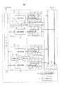
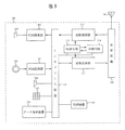
図1および図2は、図4における主交換装置300あるいは子交換装置200の本発明に関連する部分の第1及び第2の実施例を示すものであり、図3は端末装置100の一実施例を示す。以下、図1を用いて第1の実施例について詳細に説明する。
2.a 第1の実施例
この実施例は、図1に示す如く変復調装置210をトラヒックに応じ、同時通話/通信数だけ設ける方式で、変復調装置210は一回線分の情報しか扱わないので低速で動作する特徴がある。
【0013】
図4における端末装置100と交換装置200または300との間の情報は、インテグレィテイッド・サ−ビス・ディジタル・ネットワ−ク(ISDN:Integrated Services Digital Network)として標準化されつつある、音声あるいはデ−タ用の64kb/sのチャネルBと、デ−タおよび信号用の16kb/sのチャネルDから成るものとする。図5は、交換装置内のハイウェイ上と、交換装置と端末装置間の伝送路上の上記チャネルBおよびDの関係を示したものである。図5(a)は音声中心の場合で、端末装置とはB+Dの情報をやりとりする場合、図5(b)はISDNの標準になると考えられているB+B+Dの情報をやりとりする場合である。
【0014】
図5(a)のフレ−ムとは、毎秒8000サンプルの割合で音声がサンプリングされる、1サンプル分の時間で125us相当する。このフレ−ム内にはn個のタイムスロットが時分割多重化されており、1つのタイムスロット、例えばTS0は8ビットで構成されている。端末装置への伝送路へ送出する場合には、Dチャネルとしての2ビットを加え、時間的に伸長して、80kb/sの速度で送出される。端末装置から送られてきた情報は、逆にDチャネルの2ビットを取り去った上で、時間的に圧縮され、ハイウェイ上の指定されたタイムスロットに挿入される。また、図5(b)は、前記B+B+Dの場合で、端末装置との信号速度は144kb/sになる。なお、図ではB+BとしてタイムスロットTS0とTS1を割当ててあるが、必ずしも隣接するタイムスロットとは限らず、また異なるハイウェイの場合もあり得る。本実施例では、簡単のために図5(a)の場合で説明する。
【0015】
先ず、通話/通信状態に無い場合、図1の交換装置200/300においては、中央制御装置240は信号受信分配装置230を介して変復調装置210を制御し、発呼検出に備える。即ち中央制御装置240は空き変復調装置210を指定し、仮にプリアンブル同期を採用しているとすれば当該変復調装置210の擬似雑音符号発生器(以下PN発生器と言う)213に発呼検出すべき端末装置100に割当てられているプリアンブル符号と擬似雑音符号(以下PN符号と言う)を指定し、同期捕捉のためプリアンブル符号で拡散復調器212を駆動する様指示する。複数の端末装置の発呼検出に当たっては中央制御装置240は、変復調装置210の復調部が同期捕捉するに充分な時間をおいて、復調部を発呼の可能性のある端末装置100のプリアンブル符号およびPN符号で逐次切替えて駆動し、発呼検出してゆく。この場合、複数の変復調装置210を使い、同時に複数の発呼検出を行なうこともできる。
【0016】
即ち、公知の交換装置においては、中央制御装置がラインインタフェ−ス回路を空間的にスキャンするのに対し、本発明のシステムの交換装置においては、中央制御装置240が変復調装置210を用い、拡散復調器212のプリアンブル符号およびPN符号を逐次切替えてスキャンし、同期捕捉が行なわれた場合に発呼とみなすことになる。なお、同一端末装置に与えられたPN符号が、上り(端末装置から交換装置への伝送)と、下り(交換装置から端末装置への伝送)で異なる場合には、前記拡散復調器212に設定されるPN符号は上り用の符号になる。次に端末装置100においても、通話/通信状態に無い場合には、図3における拡散復調器112のみが、PN発生器113によって発生された、自端末装置の下りプリアンブル符号で同期捕捉動作を行ない、受信準備している。
2.a.1 発信動作
まず、端末装置の発信動作を図1、図3及び図6のフロ−チャ−トを用いて説明する。
【0017】
図4の#m1端末装置100において送受器を上げると(図6、601)、図3に示す制御装置140がこれを検出する(図示省略)。制御装置140はインタフェ−ス回路150を介してPN発生器113に、上りプリアンブル符号を拡散変調器111へ供給するよう指示し、拡散変調器111からプリアンブル信号を送出する。自端末装置の上りプリアンブル符号でスペクトラム拡散変調されたプリアンブル信号が、送受信機120で所定の電力まで増幅され、アンテナ130から送出される(図6、602)。
【0018】
アンテナ130から送出されたプリアンブル信号は、図1のアンテナ500で受信され、送受信機220で増幅され、すべての変復調装置210の拡散復調器212に入力される。今、No.1変復調装置210の拡散復調器212が、中央制御装置240の発呼検出のための制御によって前記#m1発呼端末装置の上りプリアンブル符号にセットされているとすれば、同期回路214が作動し、同期捕捉する(図6、611)。
【0019】
交換装置200/300では、No.1変復調装置210の同期回路214から、同期捕捉したと言う信号が、信号受信分配装置230を通して、中央制御装置240へ送られる。中央制御装置240はNo.1変復調装置210の拡散復調器212が#m1端末装置の上りプリアンブル符号で同期捕捉したことを知り、#m1端末装置が発呼したことを識別する(図6、612)。
【0020】
中央制御装置240は、No.1変復調装置210の拡散変調器211に対し、#m1端末装置100の下りプリアンブル符号およびPN符号をPN符号発生器213にセットする(図6、613)。これによって拡散変調器211は下りプリアンブル信号を、送受信機220、アンテナ500を通して送出する。
【0021】
#m1発呼端末装置100では、このプリアンブル信号をアンテナ130、送受信機120を通して拡散復調器112で受け、同期回路114の制御で同期捕捉する(図6、603)。これによって上り回線、下り回線共に同期捕捉したことを、#m1端末装置100は確認できるので、上り回線のスペクトラム拡散符号をプリアンブル符号から通信用のPN符号に切替え、以後、同期回路114は同期追跡を続ける。切替に先立って、端末装置100は切替信号をプリアンブル信号に乗せて交換装置200の拡散復調器212に送り、端末装置側の拡散変調器111と交換装置側の拡散復調器212は同期をとりながらPN符号への切替を行なう(図6、604、および図6、615)。
【0022】
交換装置200では、拡散復調器212がプリアンブル符号から通信用のPN符号に切替ったことによって、端末装置100でも下りプリアンブル信号を同期捕捉したことを確認し、下りプリアンブル信号に切替指示信号を乗せて送り、上り回線と同じ手順で下り回線をプリアンブル符号から通信用のPN符号に切替える(図6、616、および図6、605)。
【0023】
以上の動作によって、端末装置100と、交換装置200の間の双方向の回線が設定されたので、交換装置200においては発呼端末装置に対し発信音を送出し(図6、617)、ダイヤルの監視に入る。これ以降の交換装置の動作は、公知の交換装置の動作と同様に行なわれる。回線設定後の通信は、図5で説明した様に通話および高速デ−タはBチャネルを用い、制御信号および低速デ−タはDチャネルを用いて行なわれる。
【0024】
発信音送出以降の動作を図1および図3を用いて簡単に説明する。
【0025】
中央制御装置240は、No.1変復調装置210の拡散変調器211の拡散符号がプリアンブル符号からPN符号に切替ったことをPN発生器213から信号受信分配装置230を通して検知すると、発信音送出回路(図示省略)とNo.1変復調装置210とを、例えば送信ハイウェイ261、スイッチングネットワ−ク250、受信ハイウェイ260を通し空きタイムスロットを選んで接続する。ここでスイッチングネットワ−ク250は、タイムスイッチ、空間スイッチ、あるいは両者を組み合わせたもののいずれであっても良い。
【0026】
上記接続が行なわれた時、中央制御装置240は信号受信分配装置230を通して、No.1変復調装置210におけるバッファメモリ215内のタイムスロットメモリ215−2に選んだ受信ハイウェイ260上のタイムスロットを記憶させる。以後、当該タイムスロットにおいて、タイムスロットスイッチ215−1を閉じ、8ビットの符号化発信音をシフトレジスタ215−3において受信する。シフトレジスタ215−3に入った8ビットの情報は、直ちに、もう一つのシフトレジスタ215−4に転送され、シフトレジスタ215−3は次のフレ−ムの当該タイムスロットの信号の受信に備える。
【0027】
シフトレジスタ215−4に転送された8ビット情報の後には、計2ビットのデ−タおよび制御ビットが、中央制御装置240の制御で付加され(図1のシフトレジスタ215−4のハッチング部分)、図5(a)に示すように80kb/sの速度で拡散変調器211に送り込まれ、#m1端末装置に与えられた下りPN符号でスペクトラム拡散変調され、送受信機220で増幅され、アンテナ500から送信される。
【0028】
#m1端末装置100では、この信号を図3に示す如くアンテナ130で受信し、送受信機120で増巾し、拡散復調器112に入力する。
【0029】
拡散復調器112では、自端末装置(#m1)の下りPN符号で復調し、制御装置140の制御によってインタフェ−ス回路150を介し、Bチャネルの信号のみが取出され、PCM復調器162に所定の速度に変換して送出される。PCM復調器162では8000サンプル/秒の割合で送られて来る8ビットコ−ドをアナログ信号に直し、所定の電力で受話器164を動作させ、発呼者に発信音を聞かせる。
【0030】
発呼者がダイヤル165によって、接続先の番号をダイヤルすると、制御装置140がインタフェ−ス回路150を介してこれを検出し、インタフェ−ス回路150を介して拡散変調器111に対し、図5のDチャネルの位置に所定のコ−ドで入力し、上りPN符号で拡散変調した上で、送受信機120で増幅してアンテナ130から送信する。
【0031】
交換装置側では、この無線信号は図1のアンテナ500で受信され送受信機220で増幅された後拡散復調器212で復調され、信号はシフトレジスタ216−4に送り込まれる。制御信号は図中、ハッチング部分に入力されるので、この部分が信号受信分配装置230経由で、中央制御装置240に読み取られる。
【0032】
所定のダイヤルを受け終ると、中央制御装置240は被呼端末装置を識別し、呼出し動作を行なった後発呼端末装置との間の空きチャネル、即ち発呼端末装置側の送信、受信両ハイウェイの空きタイムスロット、被呼端末装置側の送信、受信両ハイウェイ上の空きタイムスロットを選択し、信号受信分配装置230を通して、発呼、被呼端末装置210のタイムスロットメモリ215−2および216−2へ、選択したタイムスロット番号を書き込む。一方、スイッチングネットワ−ク250を制御して発呼側タイムスロットと被呼側タイムスロットを接続する。
2.a.2 着信動作
次に、被呼端末装置の呼出動作を、図1、図3および図7のフロ−チャ−トによって説明する。
【0033】
図1で、中央制御装置240がダイヤル(被呼番号)を受信すると(図7、711)、該番号がどの端末装置のものかを識別する。今、被呼端末装置が図4における#miであるとすると、中央制御装置240は、被呼端末装置#miを呼出可能な、空き変復調装置、例えば図1、No.n変復調装置210を選択、捕捉する(図7、712)。
【0034】
続いて中央制御装置240は、被呼端末装置#miに割当てられた、上り、下りそれぞれのプリアンブルおよび通信用PN符号を、信号受信分配装置230を介して、No.n変復調装置210のPN発生器213にセットする(図7、713)。これによって拡散変調器211はプリアンブル信号の送出を始め(図7、714)、拡散復調器212は#mi端末装置からの上りプリアンブル信号の受信に備える。プリアンブル信号は送受信機220、アンテナ500を通して送信され、#mi端末装置100では、図3のアンテナ130で受信され、送受信機120を通して拡散復調器に入力される。発呼の場合に説明した様に、端末装置が空きの状態では、拡散復調器112は常に同期捕捉できる様、プリアンブル符号で動作しているので、プリアンブル信号が入力されると同期回路114の制御によって同期捕捉が行なわれる(図7、701)。
【0035】
下りプリアンブル信号を同期捕捉すると、直ちに制御装置140の制御によって、上りプリアンブル信号を拡散変調器111から送受信機120、アンテナ130を通して送信する(図7、702)。この上りプリアンブル信号は、図1のアンテナ500、送受信機220を通して拡散復調器212に入力される。
【0036】
No.n変復調装置210の拡散復調器212は、上述の如く、すでに#mi端末装置からのプリアンブル信号を受信する様設定されているので、入力されたプリアンブル信号は直ちに同期捕捉される(図7、715)。
【0037】
同期捕捉完了によって拡散変調器211は、#mi端末装置100と同期をとりながら、プリアンブル符号を通信用のPN符号に切替える(図7、716)。端末装置100でも、これに応動して拡散復調器112の符号を、プリアンブル符号から通信用のPN符号に切替え(図7、703)、続いて拡散変調器111の拡散符号を、プリアンブル符号から通信用のPN符号に切替える(図7、704)。
【0038】
交換装置側では、No.n変復調装置の拡散復調器212の拡散符号を、端末装置側と同期をとりつつプリアンブル符号から通信用のPN符号に切替え(図7、717)、No.n変復調装置210と#mi端末装置100間の、上り、下り両無線チャネルの設定が完了する。
【0039】
以上説明した様に、プリアンブル信号による同期捕捉、通信用PN符号への切替を、コンペルド形式で行なわせているので、図7、717の符号切替によって、中央制御装置240は下り、上り両チャネルが設定完了したことを確認できる。
【0040】
以後、中央制御装置240は通常の交換装置におけると同様、発呼者には呼出音を送出し、被呼者には呼出信号を送出するよう制御を行なう(図7、718)。なお呼出信号の送出に当っては、中央制御装置240の制御によって、呼出信号送出を制御する命令を図5におけるDチャネルにのせて端末装置に伝送し、端末装置100では、制御装置140がこれを受信してリンガ−166を駆動する。
【0041】
以上説明した様に、発呼あるいは着信時に、空き変復調装置210を使って端末装置100と交換装置200の間に、スペクトラム拡散通信による無線チャネルを設定することによって、同時通話/通信数がnのワイヤレス通信システムが実現できる。この方式では、交換装置側の設備は、同時通話/通信数がnの範囲内においては、端末装置数に無関係になるので、比較的端末装置当たりの呼量が小さい適用領域では、経済的である。
【0042】
また上記実施例では、図4における端末装置#m1と#miが、当該フロアの子交換装置200を通して通話する場合について説明したが、主交換装置300を介して、例えば#1と#l端末装置が通話/通信する場合も同じであり、また#m1端末装置と#nj端末装置が、#mおよび#n子交換装置を通して通話/通信する場合も、交換装置の交換動作が多少異なるだけであって、端末装置と交換装置内の変復調装置間の無線チャネルの設定、発呼検出、呼出等の、本発明に関する部分については同じである。従って、交換方式は、分散制御、集中制御あるいは時分割通話路の構成等によって何ら影響されることなく、本発明を適用可能である。
【0043】
交換装置−端末装置間の信号の伝送方法も、実施例における図5(a)の形式に限定されるものでは無く、図5(b)に示すB+B+Dでも良いし、全く異なる方式であっても何ら支障ない。更に実施例においては、電話の場合について、ダイヤル165で発信し、スピ−カからト−ンリンガ166で呼出し、送受話器163、164で通話する場合について説明したが、通話路設定後、端末装置100内の拡散変復調装置111、112とPCM変復調器161、162の接続を、デ−タ端末装置170に切替えてデ−タ通信を行なうことも可能であるし、ダイヤル165の代りにデ−タ端末装置170内のキ−ボ−ドを使って相手番号/符号を入力して接続を行なうことも可能であることは言うまでも無い。
【0044】
本実施例は、電話を対象に、1タイムスロット8ビット、8000フレ−ム/秒の場合について説明したが、端末装置−交換装置間に、ディジタル無線チャネルが1チャネル設定されるので、交換装置がパケット交換装置であっても、画像信号を送っても何ら支障が無い。
2.b 第2の実施例
第2の実施例は、図2に示す如く交換装置からスペクトラム拡散信号による同期信号を拡散同期信号発生回路280から送信し、交換装置と端末装置をスペクトラム拡散通信チャネルを通して相互に同期しながら動作せしめることにより、交換装置側のスペクトラム拡散変復調装置210の時分割多重化使用を可能にしたものである。
【0045】
交換装置200および300は、第1の実施例と同様、毎秒、8000のフレ−ムで構成され、ハイウェイ260−1〜260−rおよび261−1〜261−r上では1フレ−ムはn個のタイムスロットから成るものとする。これらのフレ−ム、タイムスロット等は、図2の同期信号発生回路270から供給される同期信号によって、同期がとられている。
【0046】
各端末装置100には、個別に、スペクトラム拡散用のPN符号、PNU(上り用)およびPND(下り用)が与えられる。端末装置J(図4では図示省略)に対するPN符号をPNUjおよびPNDjと表わす。本実施例では、さらに、同一同期信号で動作する全端末装置に共通の、同期信号受信用のPN符号PNCが設けられる。このPNCはプリアンブル符号の役割も果たす。
【0047】
交換装置、例えば200が動作状態に入ると、図2の拡散同期信号発生回路280が同期信号発生回路270からの同期信号を受けて、端末装置同期信号を拡散符号PNCでスペクトラム拡散し、送受信機220、アンテナ500を通して送信する。送信される拡散同期信号を図示したものが、図8である。
【0048】
図8(a)は、交換装置から送信される拡散同期信号を時間軸上で示したもので、図の横軸の下側のPNCは、横軸の上側の信号SNC1〜SNCnが拡散符号PNCで拡散変調されていることを示す。同期信号SNC1〜SNCnは、タイムスロットに対応しており、受信側ではこれを受信することにより、タイムスロット番号を識別できる。即ちフレ−ム同期信号にもなっている。
【0049】
ここで、この同期信号はプリアンブル信号も兼ねているので、同期捕捉までの時間を短くするためには拡散符号PNCは簡単な符号であることと、同じ符号の繰り返しであることが要求されるので、拡散符号PNCの長さは、タイムスロット長あるいはその整数分の一であることが好ましい。
2.b.1 端末装置立上り動作
端末装置側では、電源が投入されると共に前記同期信号を受信して同期捕捉し、以後は交換装置200/300と同期した状態で着信の待期あるいは発信動作をする。この状態を図3、図8及び図9のフロ−チャ−トにより説明する。
【0050】
図8において、端末装置Jの電源投入は、交換装置の動作とは無関係に行なわれるので、最初は同期がとれていない。
【0051】
端末装置Jの電源が投入されると(図8(b))、図3の制御装置140が起動され、制御装置140の制御によって動作を開始する(図9、901)。先ず、PN発生器113が拡散同期信号受信用のPN符号PNCを発生し(図9、902)、拡散復調器112は、PN符号PNCで復調動作を開始する(図9、903)。一方、同期回路114は、PN発生器113を制御して同期捕捉動作を開始する(図9、911)。電源投入時、図8(b)に示す様に、受信信号と拡散復調器112のPN符号は、同期がとれていないので拡散復調器112から出力は得られないが、同期回路114の制御で受信信号と同期がとれると、拡散復調器112から出力が得られ(図9、904)、同期捕捉が完了し(図9、912)、同期回路114は同期捕捉動作から、同期追跡動作に移る(図9、913)。
【0052】
同期捕捉を完了したことにより、受信同期信号から交換装置のタイムスロット番号が得られるので、これによって端末装置100内のクロック、タイムスロット、フレ−ム等の同期信号を交換装置に合わせる。以後は図8(b)に示す如く、略1フレ−ム毎に受信する同期信号によって同期ずれを修正する。
【0053】
制御装置140は、同期捕捉が完了したことにより、PN発生器113を制御して拡散復調器112へのPN符号をPNCから自端末装置に与えられた下りPN符号PNDjに切替え(図9、905)、拡散復調器112はPN符号、PNDjで復調動作を開始する(図9、906)。この時端末装置100では、交換装置200/300がどのタイムスロットで呼出して来るかわからないので、図8(b)に示す様に全タイムスロットについてPNDjで復調動作を行なう。同期維持のため、例えば図8(b)に示す様にn+1タイムスロット目毎に、PN発生器113を制御して拡散復調器112のPN符号をPNCに変えて同期信号を受信する。
【0054】
制御装置140は拡散復調器112の出力を監視し、信号が検出されない場合には次のタイムスロットでの復調動作を続け(図9、907)、信号が検出された場合は、当該タイムスロットを使って着信があったことを識別し、拡散復調器112の動作を当該タイムスロットに固定し、誤動作防止のためそれ以外のタイムスロットでの復調動作は停止する(図9、908)。なお同期信号の受信も、制御を簡単にするために例えば後述する様に当該タイムスロットの1つ前のタイムスロットに固定する。
【0055】
以上の動作のうち、図9、907の判定がノ−となる場合の動作が、端末装置が空き状態の場合の動作である。
2.b.2 発信動作
次に、端末装置が発信する場合の動作を図2、図3、及び図10の時間関係図、並びに図11のフローチャートを使って説明する。
【0056】
発呼者が端末装置Jの送受器を上げると、フックスイッチ(図示省略)が閉じたことを図3の制御装置140が検出し(図11、1101)、インタフェース回路150を介してPN発生器113から上りPN符号(PNUj)を発生させ、拡散変調器111によって起呼信号を、全タイムスロットを用いて該PN符号で拡散変調させて、送受信機120、アンテナ130を通して送信する(図11、1102)。ここで、拡散変調される信号は、例えば図5に示す如く、B+D、あるいはB+B+D等の構成を持つ信号で、ここではB+Dの形式を仮定して説明する。即ち、図10(a)の横軸上部のTS1,TS2等はタイムスロット番号を表わし、ハッチング部分がD信号、ハッチングのない部分がB信号を表わす。図10(a),(b),(e),(f)において、各フレームがTS1から始まっていないのは、交換装置のハイウェイを基準にしているためである。
【0057】
起呼信号は、特定パターンの信号、あるいは発呼者、発呼条件(電話、データ等)を送るものとし、システムによって決まる。また、時間関係においては、図8(b)、および図10(f)に示す、交換装置から送られて来る同期信号SNC〜を基準に、交換装置と同期をとって送信する。
【0058】
交換装置200/300においては、図2の中央制御装置240が各変復調装置210(同一サービス地区内に複数の変復調装置が設けられている場合には、少なくともそのうちの一つ)について、空きタイムスロットを用いて各端末装置100の上りPN信号(PNU〜)で逐次拡散復調器212を駆動し、空き全端末装置について発呼の有無をスキャンする(図11、1111)。
【0059】
今、図10(b)について説明する。対応する交換装置側の変復調装置210をNo.1装置とすると、中央制御装置240はフレームqのタイムスロット1(ハイウェイ上)において、端末装置mの発呼検出のため、No.1装置のPN発生器213に、端末装置mの上りPN符号PNUmを発生させ、拡散復調器212を起動させたが、信号は得られず、発呼は検出されなかったことを示す。続くタイムスロット2(ハイウェイ上)は、すでに端末装置iとの通信に使われている。
【0060】
フレームqのタイムスロット3(ハイウェイ上)では、端末装置Jの発呼検出のため、タイムスロット1の場合と同様の制御により、PN符号PNUjで拡散復調器212を駆動する(図11、1112)。端末装置Jでは図10(a)に示すように、すでに起呼信号をPN符号PNUjで拡散変調して送信しているので、拡散復調器212でこの起呼信号が復調され、制御装置217で検出される。そして信号受信分配装置230経由で中央制御装置240へ通知される(図11、1113)。中央制御装置240は、拡散復調器212がPN符号PNUjで起呼信号を検出したことから、端末装置Jが発呼したことを識別する(図11、1114)。
【0061】
中央制御装置240は、発信音接続(発信音の送出、あるいは押釦信号受信器への接続等)のため、上り(ハイウェイの送信)タイムスロットと、下り(ハイウェイの受信)タイムスロットを選択する。このとき、上りタイムスロットは、起呼検出に使ったタイムスロットでも、異なるタイムスロットでも良い(図11、1115)。続いて、選択した下りタイムスロット、例えばTSn(ハイウェイ上ではタイムスロット1)において、No.1変復調装置210の拡散変調器211をPN符号PNDjで動作させるよう、信号受信分配装置230経由で制御装置217に指示すると共に、上りタイムスロットも、例えばTS2(ハイウェイ上のタイムスロット3)を端末装置Jに割当てるよう指示する。
【0062】
制御装置217はPN発生器213を制御し、拡散変調器211はタイムスロットTSnにおいてPN符号PNDjで動作し、拡散復調器212はタイムスロットTS2においてPN符号PNUjで動作するよう設定する(図11、1116)。同時にバッファメモリ215経由で、前記上りタイムスロット番号TS2を信号として拡散変調器211へ入力し、端末装置Jへ送信する(図10(e)、図11、1117)。
【0063】
なお、この時点では変復調装置210とハイウェイ260〜/261〜を接続する必要はない。また、上りタイムスロットが、起呼検出に使ったタイムスロットから変わる様なシステムにおいては、上りタイムスロット番号を端末装置へ送った後、端末装置の拡散変調器111と同期をとりながら、交換装置側のタイムスロットの切替えを行なうことが好ましい。図2の同期回路214は、拡散復調器212の同期追跡を行なう。
【0064】
端末装置Jにおいては、図8(b)および図10(f)に示す様に、拡散復調器112(図3)が全タイムスロットにおいてPN符号PNDjで動作しているので、タイムスロットTSnにおいて上りタイムスロット番号TS2を受信し(図11、1103)、交換装置200/300において起呼検出が行なわれたことを確認すると、制御装置140がPN発生器113を制御して、拡散変調器111の動作をTS2に固定し、さらに拡散復調器112の動作をTSnに固定する(図10(a),(f)、図11、1104)。
【0065】
端末装置100における同期信号の受信は、どのタイムスロットに着信があっても、たかだか1フレ−ム遅れで信号検出ができる様n+1タイムスロット目毎に受信すると仮定(図8(b))したが、通信用タイムスロットが固定した後は、同期信号を受信するタイムスロットも固定する。これはn+1タイムスロット目毎に同期信号を受け続けるとnフレ−ムに1回、通信用タイムスロットで同期信号を受けることになるためで、図10の例では、通信用タイムスロットの一つ前のタイムスロットで同期信号を受信している。
【0066】
交換装置側では、端末装置100へ上りタイムスロット番号を送出した後、(端末装置100から上りタイムスロット番号を受信したことを確認する信号を送らせ、これを受信した後にしても良い)、例えば押釦信号受信器(図示省略)を選択捕捉し、すでに発呼端末用に選択してあるハイウェイ上のタイムスロットとの間のチャネルを設定すると共に、このハイウェイ上のタイムスロット番号で、図2のバッファメモリ、215および216を動作させ、No.1変復調装置210とハイウェイ260−1および261−1を接続する(図11、1118)。
【0067】
押釦信号受信器から発信音が送出され、端末装置でダイヤルすると、ダイヤルに対応した多周波信号が押釦信号受信器に送られる。
【0068】
なお、端末装置100内における多周波信号送出動作の詳細は説明を省略するが、制御装置140が受信したダイヤル信号に対応した、PCM符号化された多周波信号を、拡散変調器111に逐次入力することによって行なわれる。
【0069】
以上の動作で、端末装置100と交換装置200/300間の無線チャネルが設定されたので、以後の交換装置200/300の動作は、公知のものと同様に行なわれる。なお、以上の説明中、例えば図10で上りタイムスロット番号を交換装置から端末装置に送る場合、1フレ−ム内に送る如く書いてあるが、Dチャネルを使って、複数フレ−ムにわたって送っても、何ら支障の無いことは明らかであり、図に限定されるものでは無い。説明を省略したが、Dチャネルの付加等は、図1に示す、第1の実施例と同様の方法でバッファメモリ215、216内で行なわれる。
2.b.3 着信動作
図2、図3、及び図12の時間関係図、並びに図13のフローチャートによって着信の場合の動作を説明する。
【0070】
図2において、中央制御装置240が被呼番号を受信すると(図13、1311)、直ちに被呼番号から被呼端末装置が例えば“J”であることを識別する(図13、1312)。続いて中央制御装置240は、被呼端末装置Jを呼出すことのできる変復調装置210を選択する。端末装置Jを呼出し得る変復調装置210が唯1個の場合には、一義的に決まるが、複数個ある場合には発呼端末あるいは入回線との間に空チャネルのある変復調装置を選択する(図13、1313)。
【0071】
これと併行して、発呼端末装置あるいは入回線と選択した変復調装置210、例えばNo.n装置との間の空きタイムスロットを送信、受信両ハイウェイ260−r、261−r上において選択する。本実施例では、ハイウェイのタイムスロットと無線チャネルのタイムスロットを対応させているので、No.n変復調装置210と被呼端末装置Jとの間に上り、下り両タイムスロットを選択したことになる(図13、1314)。ここで、上りタイムスロットとしてTSn、下りタイムスロットとしてTS2が選択されたとする(図12)。
【0072】
以上によって、変復調装置210、端末装置100、上り、下りタイムスロットがそれぞれNo.n、No.J、TSn、TS2と決まったので、中央制御装置240は、信号受信分配装置230を介してNo.n変復調装置210の制御装置217に指示を与え、制御装置217の制御により拡散変調器211はタイムスロットTS2においてPN符号PNDjで拡散変調動作をするよう(図13、1315)、また拡散復調器212はタイムスロットTSnにおいてPN符号PNUjで拡散復調動作をするよう(図13、1316)、設定する。
【0073】
さらに制御装置217は、タイムスロットTS2において下りバッファメモリ215に、着信信号として必要な情報と、使用すべき上りタイムスロット番号TSnを入力し、拡散変調器211で、PNDjで拡散変調して送受信機220、アンテナ500を通して送信する(図12(b)、図13、1317)。
【0074】
No.J端末装置100においては、アンテナ130でこの信号を受信し、送受信機120で増幅し、拡散変調器112へ入力する。No.J端末装置100では、図8(b)に示すように、常時拡散復調器112がPN符号PNDjで全タイムスロットにおいて、拡散復調動作を行なっているので、送受信機120から入力された信号は直ちに復調され、着信信号、上りタイムスロット番号TSnが信号として検出される(図12(c)、図13、1301)。
【0075】
端末装置100では、制御装置140がインタフェース回路150を通してこれを受信し、着信処理をすると共に、PN発生器113を制御して拡散復調器112の動作をタイムスロットTS2に固定し、一方、同期信号の受信を1つ前のタイムスロットに固定する。即ちタイムスロットTS1の位置でPN符号PNCで復調動作させ、同期信号SNC2を受信させる(図12(c)、図13、1303)。
【0076】
同様に、拡散変調器111に対しても、受信したタイムスロットTSnにおいて動作するよう、PN発生器113を制御する(図12(d)、図13、1302)。制御装置140は、拡散変調器111に着信信号を受信したことを確認する確認信号を入力し、送受信機120、アンテナ130を通して交換装置200/300に対して送出する(図13、1304)。
【0077】
以上の動作によって、交換装置200/300と端末装置100との間のチャネルが設定されたので、制御装置140はインタフェース回路150経由で、リンガー166を鳴動させ、呼出信号を送出する(図13、1305)。
【0078】
一方、交換装置側では、すでにNo.n変復調装置210の拡散復調器212は、タイムスロットTSnにおいてPN符号PNUjで動作しているので、端末装置100から送られて来た確認信号は、直ちに復調され(図13、1318)、制御装置217から信号受信分配装置230経由で中央制御装置240に転送される。中央制御装置240は端末装置との間のチャネル設定を確認できたので、呼出音送出等の着信接続処理を行なう(図13、1319)。
【0079】
以上のように、本発明によれば交換装置−端末装置間をワイヤレス化することが可能になる。
【0080】
なお、図12の(b)、(e)の状態を参考のため説明すると、先ず(b)は、タイムスロットTSnは端末装置Kに、タイムスロットTS1は端末装置Iに使われており、タイムスロットTS2はフレームqから端末装置Jに使われ始めたことを示している。
【0081】
図12(e)は、フレームqのタイムスロットTSn(ハイウェイではTS1)では端末装置Mの発呼検出が行なわれたが、発呼検出をしていなかったことを示しており、フレームq+1からタイムスロットTSnは端末装置Jに使われたことを示している。従って、以後の発呼検出は他の空きタイムスロットを使って行なわれることになる。また、タイムスロットTS1は端末装置Kに、タイムスロットTS2は端末装置Iに使用されていることを示している。
【0082】
以上、第2の実施例について簡単に説明したが、無線回線が設定された後は、端末装置内にタイムスロットメモリを持った、ディジタル交換システムと同じ動作をすることは明らかであり、公知の通信システムの機能はすべて導入可能である。
【0083】
本実施例では、交換装置のハイウェイをそのまま、交換装置−端末装置間の無線チャネルに延長した例を説明したが、図2のバッファメモリ215および216にタイムスイッチの機能、即ちタイムスロット入れ換えの機能を持たせれば、無線チャネル上のタイムスロットの割当ては、交換装置のハイウェイとは全く独立に決めることができるし、タイムスロット数、即ち伝送速度も独立にすることが可能である。例えば、無線チャネルのタイムスロットは、各端末装置にくくりつけにしておき、バッファメモリ215、216からハイウェイへ接続するところで集線する等の構成も可能になる。
【0084】
また、第2の実施例は、図4に示す通り、主交換装置、子交換装置共に交換機能を有している、換言すれば、同一子交換装置に収容された端末装置間の接続は、子交換装置内で処理される場合であるが、図2のバッファメモリ215および216にタイムスイッチの機能を持たせ、ハイウェイ260−1〜260−r、261−1〜261−rはケーブル600(例えば光ファイバによる高速ディジタルハイウェイ)そのもので置き換え、主交換装置内に設けられた中央制御装置240と変復調装置210内の制御装置217との通信は、ハイウェイ上のタイムスロットの一部を信号チャネルとして用いるよう構成すれば、図4の子交換装置は、変復調装置210そのもので良くなる。なお、このときは、同一変復調装置内の端末装置間の通信も、すべてノード装置610、ケーブル600を介し、主交換装置300経由で行なわれることになる。換言すれば、変復調装置210を遠隔集線装置として用いる交換システムを構成することも可能である。
【0085】
以上の実施例は、64kb/sの音声を基準にしたISDNについて説明したが、例えば、タイムスロットを大きくすれば、メッセージスロット方式のパケット通信に利用することも可能である。
【0086】
また、本発明の交換システムは、端末装置から交換装置へのアクセスチャネルは、端末装置が個別にもっているので、機能上はスター形の配線をしてあるのと等価になり、従ってコンテンション制御を交換装置で行なえば、即ち、端末装置が起呼信号送出後、交換装置からの通信開始許可信号を受取って通信の開始、例えばパケットの送信を行なえば、スター形ローカルエリアネットワーク(LAN)と同じ機能をも実現できる。
【0087】
スペクトラム拡散変調の特徴の一つである、耐雑音性を活かせば、高周波領域では減衰量の大きい既設の音声通信用ローカルケーブルを用いて有線伝送も可能で、ISDNにおける加入者線伝送方式としても活用できる。
【0088】
第2の実施例に示したような、時分割多重化した信号をスペクトラム拡散変調する場合において、端末装置と交換装置間の伝送路としてツイステッドペア、あるいは同軸ケーブル等の有線伝送路を用い、しかも同一ケーブル上に複数の端末装置を接続する、いわゆる連接形、あるいはマルチドロップ形にすれば、空間電磁波を用いることなく、一本のケーブルで複数の端末装置−交換装置間の通信を提供することも可能になる。
【0089】
この方式は、鉄道沿い、道路沿い、あるいは電力線沿いに設置されたケーブルを用いて通信するような場合、一本のケーブルで多数の端末に独立した複数の通信路を提供し得るので、非常に経済的である。
【0090】
【発明の効果】
本発明によれば、高速に同期を獲得できると共に、秘話性、耐雑音性が高く、かつ、ディジタル交換方式を採用している電話交換システムへの適合性が良い無線電話交換システムを提供することができる。また、これによって、オフィス内の配置換え、端末装置の移動等の場合にも、一切の配線工事が必要ないので、極めてフレキシブルな電話交換システムを構築できる。特に、オフィス内への適用においては、電波も微弱電波が使えるので、電波管理上の問題もなく、システムをワイヤレス化できる効果を有する。
【図面の簡単な説明】
【図1】本発明の第1の実施例を示す交換装置側のシステム構成図である。
【図2】本発明の第2の実施例を示す交換装置側のシステム構成図である。
【図3】本発明による端末装置側の一実施例を示すシステム構成図である。
【図4】本発明による交換システムの一例を示す分散交換システムの構成図である。
【図5】本発明の第1の実施例のハイウェイ上の信号と端末装置への無線伝送路上の信号の関係を示す時間関係図である。
【図6】本発明の第1の実施例の起呼動作を示すフローチャートである。
【図7】本発明の第1の実施例の着信動作を示すフローチャートである。
【図8】本発明の第2の実施例の同期信号と端末装置の電源投入から同期捕捉着信待機に到る復調動作の信号の状態を示す時間関係図である。
【図9】本発明の第2の実施例の端末装置の電源投入から着信待機に到る動作を示すフローチャートである。
【図10】本発明の第2の実施例の起呼動作時の信号の関係を示す時間関係図である。
【図11】本発明の第2の実施例の起呼動作を示すフローチャートである。
【図12】本発明の第2の実施例の着信動作時の信号の関係を示す時間関係図である。
【図13】本発明の第2の実施例の着信動作を示すフローチャートである。
【符号の説明】
100…端末装置、 111…拡散変調器、 112…拡散復調器、
113…PN発生器、 114…同期回路、 120…送受信機、
130…アンテナ、 140…制御装置、
150…インタフェース回路、 161…PCM変調器、
162…PCM復調器、163…送話器、
164…受話器、 165…ダイヤル、 166…リンガー、
170…データ端末装置、
200…交換装置、 210…変復調装置、 211…拡散変調器、
212…拡散復調器、 213…PN発生器、 214…同期回路、
215、216…バッファメモリ、 217…制御装置、
220…送受信機、 230…信号受信分配装置、
240…中央制御装置、250…スイッチングネットワーク、
300…交換装置、 400…外部ケーブル、500…アンテナ、
600…ケーブル、610…ノード装置[0001]
[Industrial applications]
BACKGROUND OF THE
[0002]
[Prior art]
Taking the wireless telephone system as an example, car phones and wireless telephones have been put into practical use. In the former, phase modulation or frequency modulation is employed as a modulation method of information in a wireless part. For example, a summary can be found in Sections 239 to 260 of "New Edition / Mobile Communication System" (issued on May 10, 1979) (hereinafter referred to as "
[0003]
[Problems to be solved by the invention]
In the above prior art, since the radio transmission path between the switching device and the communication terminal device uses an analog system, there is a problem in confidentiality, noise resistance, and interference resistance. Its suitability for existing telephone switching systems was not very good either. An object of the present invention is to provide an improved switching system in order to solve the problems of the system using the analog wireless system as described above, and more specifically, to provide a telephone communication terminal device and a switching device. It is an object of the present invention to provide a device which enables wireless communication during the period, improves confidentiality and noise immunity, and improves adaptability to a telephone exchange system employing a digital exchange system. Also, if a switching device is provided with a terminal interface according to the traffic rather than the number of wireless terminals, the interface is appropriately controlled, so that a large number of terminal devices can be economically configured. It is an object of the present invention to provide a device capable of performing an exchange operation. Furthermore, a flexible system configuration that does not impose restrictions on the connection path etc. when connecting and exchanging the partner communicating with the terminal device is adopted, and a device that is easy to construct such as exchange connection, system installation and setting change is simplified. It is to provide in.
[0004]
It is another object of the present invention to provide an easy-to-use distributed device which can solve the above-mentioned problems and satisfy the above-mentioned problems even when the terminal device is moved and used in various places.
[0005]
[Means for Solving the Problems]
In order to solve the above problem, a wireless communication apparatus according to the present invention is a wireless communication apparatus that transmits and receives information to and from a plurality of terminal apparatuses via a wireless line, and includes a spread code for generating a spread code for spread spectrum modulation. A generator, a spread spectrum modulator that performs spread spectrum modulation on an input signal based on the spread code generated by the spread code generator,The spread code generator is controlled to generate a spread code for synchronization acquisition common to the plurality of terminal devices, and a spread code used for spreading the information to be communicated with the terminal device, the spread code being used for supplementing the synchronization. Means for controlling the spread code generator so as to generate a spread code for communication different from the spread code of, and a signal input based on the spread code for synchronization and a spread code for communication based on the spread code for synchronization. Control means having means for controlling the spread spectrum modulator so as to perform spread spectrum modulation on the input signal,
A transmitter that transmits, to the terminal device, a signal that is spread-spectrum-modulated based on the spread code for synchronization capture by the spread-spectrum modulator and a signal that is spread-spectrum-modulated based on the spread code for communication., Is provided.
[0006]
【Example】
1. Summary of the present invention
The present invention is economical by introducing spread spectrum modulation / demodulation technology to information transmission between a communication terminal device and a time division multiplexing switching device, and by controlling the spread spectrum modulation / demodulation device by a central control device of the switching device. It is intended to realize a simple switching system, especially a wireless switching system. When the connection between the terminal device in the office and the exchange device is made wireless, the terminal device may be considered to be stationary in use, and the problem caused by the movement of the terminal device during communication in mobile radio or the like is a problem. I do not think. Also, the distance between the terminal device and the antenna on the switching device side can be made substantially equal by a method such as installing an antenna in each room or laying a leaky coaxial cable on a ceiling or the like. Spread spectrum communication becomes possible without controlling transmission power for compensating for a distance difference from the antenna on the device side. Furthermore, the reach of radio waves transmitted from one antenna can be limited to a relatively narrow range, such as in the same room or on the same floor, so that weak radio waves can be used and radio waves can be used effectively. The pseudo-noise code for spread-spectrum modulation and demodulation is not so many in the same system when considering offices.On the other hand, the degree of confidentiality of signal decoding is not as high as in military communications. Since it is not considered required, relatively simple codes can be used. That is, the spread spectrum modulator / demodulator can be simplified.
[0007]
Based on this premise, the present invention provides a terminal device and a switching device with a transceiver including a spread spectrum modulator / demodulator, a pseudo-noise code generator, an antenna, etc., for example, from the range of radio waves transmitted from each antenna. Within a fixed area, non-overlapping pseudo-noise codes are individually provided at least for each terminal device.
[0008]
In the case of transmission from the terminal device, the terminal device transmits a calling signal subjected to spread spectrum modulation with the pseudo-noise code given to the terminal device itself, and the demodulator of the switching device captures and captures this signal. The pseudo-noise code or the information transmitted by this code is forwarded to the central control of the switching equipment, which identifies the calling terminal equipment. The central controller sets the pseudo noise code of the calling terminal in the spread spectrum modulator on the switching device side, and sets a downlink channel to the calling terminal.
[0009]
In the case of an incoming call to the terminal device, the called number is sent to the central control unit in the switching device. The called terminal device is identified from this number, and the corresponding spread spectrum modulator on the switching device side is used. The called terminal is called by setting the pseudo noise code of the demodulator to the code of the called terminal device and transmitting the control signal of the terminal device on this channel.
[0010]
In both the case of calling and the case of receiving, after the channel setting between the terminal device and the switching device by the above-described method, for example, in the case of voice, an 8-bit companded PCM code of 8000 samples / sec is given to the terminal device. The spectrum is spread by a pseudo noise code and transmitted / received. In this way, a communication system with high confidentiality and strong interference resistance can be realized. Although some modulation methods such as direct sequence and frequency hopping are considered for spread spectrum, the present invention is not affected by the modulation method.
[0011]
FIG. 4 shows an example of a communication system in a building. A main exchange 300 is placed on a floor to which a cable 400 from the outside, for example, an office line enters, and a
[0012]
FIGS. 1 and 2 show first and second embodiments of a part related to the present invention of the main switching device 300 or the
2. a First Embodiment
In this embodiment, as shown in FIG. 1, the
[0013]
The information between the
[0014]
The frame shown in FIG. 5A corresponds to 125 μs, which is the time for one sample in which sound is sampled at a rate of 8000 samples per second. In this frame, n time slots are time-division multiplexed, and one time slot, for example, TS0 is composed of 8 bits. When transmitting the data to the transmission line to the terminal device, two bits as a D channel are added, the data is expanded temporally, and the data is transmitted at a speed of 80 kb / s. Conversely, the information sent from the terminal device is temporally compressed after removing two bits of the D channel, and inserted into a designated time slot on the highway. FIG. 5B shows the case of B + B + D, where the signal speed with the terminal device is 144 kb / s. Although time slots TS0 and TS1 are assigned as B + B in the figure, the time slots are not necessarily adjacent to each other and may be different highways. In this embodiment, the case of FIG. 5A will be described for simplicity.
[0015]
First, when there is no call / communication state, in the
[0016]
That is, in the known switching device, the central control device spatially scans the line interface circuit, whereas in the switching device of the system of the present invention, the central control device 240 uses the modulation /
2. a. 1 Calling operation
First, the transmitting operation of the terminal device will be described with reference to the flowcharts of FIGS. 1, 3 and 6.
[0017]
When the handset is raised in the #
[0018]
The preamble signal transmitted from
[0019]
In switching
[0020]
The central control device 240 The downlink preamble code and PN code of the #
[0021]
In the # m1 calling
[0022]
In the
[0023]
By the above operation, a bidirectional line between the
[0024]
The operation after transmission of a dial tone will be briefly described with reference to FIGS.
[0025]
The central control device 240 When it detects from the
[0026]
When the above connection is made, the central control unit 240 sends the No. The time slot on the selected
[0027]
After the 8-bit information transferred to the shift register 215-4, a total of 2 data and control bits are added under the control of the central controller 240 (the hatched portion of the shift register 215-4 in FIG. 1). 5 (a), the signal is sent to the spread modulator 211 at a speed of 80 kb / s, spread-spectrum-modulated by the downlink PN code given to the # m1 terminal device, amplified by the
[0028]
In # m1
[0029]
The
[0030]
When the caller dials the number of the connection destination with the dial 165, the
[0031]
On the switching device side, this radio signal is received by the
[0032]
After receiving the predetermined dialing, the central control unit 240 identifies the called terminal device, performs a paging operation, and then performs an idle channel with the calling terminal device, that is, the transmission and reception highways of the calling terminal device. An empty time slot and an empty time slot on both the transmitting and receiving highways of the called terminal device are selected, and the signal is transmitted and received through the signal receiving and distributing
2. a. 2 Incoming operation
Next, the calling operation of the called terminal device will be described with reference to the flowcharts of FIGS.
[0033]
In FIG. 1, when the central control unit 240 receives the dial (called number) (FIG. 7, 711), it identifies which terminal device the number belongs to. Now, assuming that the called terminal device is #mi in FIG. 4, the central control unit 240 transmits an idle modem device capable of calling the called terminal device #mi, for example, as shown in FIG. The n modulator /
[0034]
Subsequently, the central controller 240 assigns the preamble and the communication PN code of the uplink and downlink assigned to the called terminal device #mi via the signal reception /
[0035]
As soon as the downlink preamble signal is acquired synchronously, the uplink preamble signal is transmitted from the spread modulator 111 through the
[0036]
No. As described above, since the
[0037]
Upon completion of synchronization acquisition, the spread modulator 211 switches the preamble code to the communication PN code while synchronizing with the #mi terminal device 100 (716 in FIG. 7). In response to this, the
[0038]
On the exchange device side, The spreading code of the spreading
[0039]
As described above, the synchronization acquisition by the preamble signal and the switching to the communication PN code are performed in the compeldo format. Therefore, by the code switching in FIGS. You can confirm that the setting has been completed.
[0040]
Thereafter, the central control unit 240 controls to send a ringing tone to the calling party and to send a calling signal to the called party, as in the normal switching equipment (FIG. 7, 718). In transmitting the paging signal, a command for controlling the transmission of the paging signal is transmitted to the terminal device on the D channel in FIG. 5 under the control of the central control device 240. In the
[0041]
As described above, by setting a wireless channel by spread spectrum communication between the
[0042]
Further, in the above embodiment, the case where the terminal devices # m1 and #mi in FIG. 4 communicate with each other through the
[0043]
The signal transmission method between the switching device and the terminal device is not limited to the format of FIG. 5A in the embodiment, but may be B + B + D shown in FIG. 5B or a completely different method. No problem. Further, in the embodiment, the case of making a telephone call using the dial 165, calling from the speaker using the
[0044]
In the present embodiment, a description has been given of a case in which one time slot is 8 bits and 8000 frames / second is used for a telephone. However, one digital radio channel is set between the terminal device and the switching device. Even if is a packet switching device, there is no problem in sending an image signal.
2. b Second embodiment
In the second embodiment, as shown in FIG. 2, a switching apparatus transmits a synchronization signal based on a spread spectrum signal from a spread synchronization signal generation circuit 280, and operates the switching apparatus and the terminal apparatus while synchronizing with each other through a spread spectrum communication channel. Thus, the spread spectrum modulation /
[0045]
The switching
[0046]
Each
[0047]
When the switching device, for example, 200 enters the operating state, the spread synchronization signal generation circuit 280 of FIG. 2 receives the synchronization signal from the synchronization
[0048]
FIG. 8A shows the spread synchronization signal transmitted from the switching device on the time axis. In FIG. 8A, the lower PNC on the horizontal axis indicates the signals SNC1 to SNCn on the upper axis on the spreading code PNC. Indicates that the signal is spread modulated. The synchronization signals SNC1 to SNCn correspond to time slots, and the receiving side can identify the time slot number by receiving this. That is, it is also a frame synchronization signal.
[0049]
Here, since the synchronization signal also serves as a preamble signal, the spreading code PNC is required to be a simple code and a repetition of the same code in order to shorten the time until synchronization acquisition. , The length of the spreading code PNC is preferably the time slot length or an integer fraction thereof.
2. b. 1 Terminal device start-up operation
At the terminal device side, the power is turned on and the synchronization signal is received and synchronously captured. Thereafter, the terminal device waits for an incoming call or performs an outgoing operation in synchronization with the switching
[0050]
In FIG. 8, since the power supply of the terminal device J is performed irrespective of the operation of the switching device, synchronization is not established at first.
[0051]
When the power of the terminal device J is turned on (FIG. 8B), the
[0052]
Since the completion of the synchronization acquisition, the time slot number of the switching device can be obtained from the received synchronization signal, whereby the synchronization signal such as the clock, time slot, and frame in the
[0053]
Upon completion of the synchronization acquisition, the
[0054]
The
[0055]
Of the above operations, the operation in the case where the determination in FIGS. 9 and 907 is negative is the operation in the case where the terminal device is idle.
2. b. 2 Calling operation
Next, the operation when the terminal device makes a call will be described with reference to the time relationship diagrams of FIGS. 2, 3, and 10, and the flowchart of FIG.
[0056]
When the caller raises the handset of the terminal device J, the
[0057]
The calling signal sends a signal of a specific pattern or a calling party and calling conditions (telephone, data, etc.), and is determined by the system. As for the time relationship, transmission is performed in synchronization with the switching device based on the synchronization signals SNC〜 sent from the switching device shown in FIGS. 8B and 10F.
[0058]
In the
[0059]
Now, FIG. 10B will be described. The corresponding switching apparatus-
[0060]
In
[0061]
The central control unit 240 selects an up (highway transmission) time slot and a down (highway reception) time slot for a dial tone connection (transmission of a dial tone or connection to a push button signal receiver). At this time, the uplink time slot may be a time slot used for call detection or a different time slot (FIG. 11, 1115). Subsequently, in the selected downlink time slot, for example, TSn (
[0062]
The
[0063]
At this point, there is no need to connect the
[0064]
In the terminal device J, as shown in FIG. 8B and FIG. 10F, the spread demodulator 112 (FIG. 3) operates with the PN code PNDj in all the time slots, so that the uplink is performed in the time slot TSn. When time slot number TS2 is received (FIGS. 1103 and 1103) and it is confirmed that call detection has been performed in switching
[0065]
Regarding the reception of the synchronization signal in the
[0066]
On the switching device side, after transmitting the uplink time slot number to the
[0067]
When a dial tone is transmitted from the push button signal receiver and dialing is performed with the terminal device, a multi-frequency signal corresponding to the dial is transmitted to the push button signal receiver.
[0068]
The details of the multi-frequency signal transmission operation in the
[0069]
With the above operation, the wireless channel between the
2. b. 3 Incoming call operation
The operation in the case of an incoming call will be described with reference to the time relationship diagrams of FIGS. 2, 3, and 12, and the flowchart of FIG.
[0070]
In FIG. 2, when the central control unit 240 receives the called number (FIG. 13, 1311), it immediately identifies from the called number that the called terminal device is, for example, “J” (FIG. 13, 1312). Subsequently, the central controller 240 selects a
[0071]
Simultaneously with this, the
[0072]
As described above, the
[0073]
Further, the
[0074]
No. In J
[0075]
In the
[0076]
Similarly, the
[0077]
With the above operation, the channel between the switching
[0078]
On the other hand, the switching device already has No. Since the
[0079]
As described above, according to the present invention, it is possible to make wireless between the switching device and the terminal device.
[0080]
It should be noted that, for reference, the states of (b) and (e) of FIG. 12 will be described. First, (b) shows that the time slot TSn is used for the terminal device K and the time slot TS1 is used for the terminal device I. The slot TS2 indicates that the terminal device J has started to be used from the frame q.
[0081]
FIG. 12 (e) shows that the call detection of the terminal device M was performed in the time slot TSn of the frame q (TS1 on the highway), but the call detection was not performed. The slot TSn indicates that it has been used in the terminal device J. Therefore, the subsequent call detection is performed by using another available time slot. The time slot TS1 is used for the terminal device K, and the time slot TS2 is used for the terminal device I.
[0082]
Although the second embodiment has been briefly described above, it is clear that the same operation as that of a digital switching system having a time slot memory in a terminal device after a wireless line is established is known. All the functions of the communication system can be introduced.
[0083]
In the present embodiment, an example has been described in which the highway of the switching device is extended as it is to the radio channel between the switching device and the terminal device. However, the
[0084]
Further, in the second embodiment, as shown in FIG. 4, both the main switching device and the child switching device have a switching function, in other words, the connection between the terminal devices accommodated in the same child switching device is In the case where the processing is performed in the slave exchange, the
[0085]
In the above embodiment, the ISDN based on 64 kb / s voice has been described. However, for example, if the time slot is increased, it is also possible to use the message slot type packet communication.
[0086]
Also, in the switching system of the present invention, since the access channel from the terminal device to the switching device is individually provided by the terminal device, it is functionally equivalent to having a star-shaped wiring, so that the contention control is performed. If the terminal device receives a communication start permission signal from the switching device and starts communication, for example, after transmitting a call signal, the terminal device transmits a call signal, for example, a packet is transmitted. The same function can be realized.
[0087]
By taking advantage of noise immunity, one of the features of spread-spectrum modulation, wired transmission is possible using an existing local cable for voice communication with high attenuation in the high-frequency range, and it can be used as a subscriber line transmission method in ISDN. Can be used.
[0088]
In the case where the time-division multiplexed signal is subjected to spread spectrum modulation as shown in the second embodiment, a wired transmission path such as a twisted pair or a coaxial cable is used as a transmission path between the terminal apparatus and the switching apparatus, and If a plurality of terminal devices are connected on the same cable, that is, a so-called connected type or multi-drop type, communication between a plurality of terminal devices and a switching device can be provided by a single cable without using a space electromagnetic wave. Also becomes possible.
[0089]
This method is very useful for communication using cables installed along railways, roads, or power lines, because a single cable can provide multiple independent communication paths to many terminals. It is economical.
[0090]
【The invention's effect】
According to the present invention, it is possible to provide a wireless telephone switching system that can acquire synchronization at a high speed, has high confidentiality and noise resistance, and has good adaptability to a telephone switching system employing a digital switching system. Can be. In addition, even in the case of rearrangement in an office, movement of a terminal device, and the like, no wiring work is required, so that an extremely flexible telephone exchange system can be constructed. In particular, in applications in offices, since weak radio waves can be used, there is no problem in radio wave management, and there is an effect that the system can be made wireless.
[Brief description of the drawings]
FIG. 1 is a system configuration diagram of an exchange device showing a first embodiment of the present invention.
FIG. 2 is a system configuration diagram of a switching device according to a second embodiment of the present invention.
FIG. 3 is a system configuration diagram showing one embodiment of a terminal device side according to the present invention.
FIG. 4 is a configuration diagram of a distributed switching system showing an example of a switching system according to the present invention.
FIG. 5 is a time relationship diagram showing a relationship between a signal on a highway and a signal on a wireless transmission path to a terminal device according to the first embodiment of the present invention.
FIG. 6 is a flowchart showing a calling operation according to the first embodiment of the present invention.
FIG. 7 is a flowchart showing an incoming call operation according to the first embodiment of the present invention.
FIG. 8 is a time relation diagram showing a state of a synchronization signal according to the second embodiment of the present invention and a signal of a demodulation operation from a power-on of a terminal apparatus to a standby state for synchronization acquisition.
FIG. 9 is a flowchart showing an operation from power-on of the terminal device to standby for incoming calls according to the second embodiment of the present invention.
FIG. 10 is a time relationship diagram showing a signal relationship at the time of a calling operation according to the second embodiment of the present invention.
FIG. 11 is a flowchart showing a calling operation according to the second embodiment of the present invention.
FIG. 12 is a time relationship diagram showing a signal relationship at the time of an incoming call operation according to the second embodiment of the present invention.
FIG. 13 is a flowchart showing an incoming call operation according to the second embodiment of the present invention.
[Explanation of symbols]
100: terminal device, 111: spread modulator, 112: spread demodulator,
113
130 ... antenna, 140 ... control device,
150: interface circuit, 161: PCM modulator,
162 ... PCM demodulator, 163 ... Transmitter
164: handset, 165: dial, 166: ringer,
170 ... data terminal device,
200: switching device, 210: modem device, 211: spreading modulator,
212: spread demodulator, 213: PN generator, 214: synchronization circuit,
215, 216: buffer memory, 217: control device,
220: transceiver, 230: signal reception and distribution device,
240: Central control device, 250: Switching network,
300 ... exchange device, 400 ... external cable, 500 ... antenna,
600: cable, 610: node device
Claims (1)
スペクトラム拡散変調用の拡散符号を発生する拡散符号発生器と、
前記拡散符号発生器が発生した前記拡散符号に基づいて入力された信号をスペクトラム拡散変調するスペクトラム拡散変調器と、
前記複数の端末装置に共通の同期捕捉用の拡散符号を発生するように前記拡散符号発生器を制御すると共に、前記端末装置と通信する前記情報の拡散に用いる拡散符号であって前記同期補足用の拡散符号とは異なる通信用の拡散符号を発生するように前記拡散符号発生器を制御する手段と、前記同期補足用の拡散符号に基づいて入力された信号並びに前記通信用の拡散符号に基づいて入力された信号をスペクトラム拡散変調するように前記スペクトラム拡散変調器を制御する手段とを有する制御装置と、
前記スペクトラム拡散変調器によって前記同期補足用の拡散符号に基づいてスペクトラム拡散変調された信号と前記通信用の拡散符号に基づいてスペクトラム拡散変調された信号とを前記端末装置に送信する送信機と、
を備えたことを特徴とする無線通信装置。A wireless communication device that transmits and receives information to and from a plurality of terminal devices via a wireless line,
A spread code generator for generating a spread code for spread spectrum modulation;
A spread spectrum modulator that performs spread spectrum modulation on a signal input based on the spread code generated by the spread code generator,
The spread code generator is controlled to generate a spread code for synchronization acquisition common to the plurality of terminal devices, and a spread code used for spreading the information to be communicated with the terminal device, the spread code being used for supplementing the synchronization. Means for controlling the spread code generator so as to generate a spread code for communication different from the spread code of, and a signal input based on the spread code for synchronization and a spread code for communication based on the spread code for synchronization. Control means having means for controlling the spread spectrum modulator so as to perform spread spectrum modulation on the input signal,
A transmitter that transmits a signal that is spread-spectrum modulated based on the spread code for synchronization and a signal that is spread-spectrum modulated based on the spread code for communication to the terminal device by the spread spectrum modulator ,
A wireless communication device comprising:
Priority Applications (1)
| Application Number | Priority Date | Filing Date | Title |
|---|---|---|---|
| JP2001142556A JP3552679B2 (en) | 2001-05-14 | 2001-05-14 | Wireless communication device |
Applications Claiming Priority (1)
| Application Number | Priority Date | Filing Date | Title |
|---|---|---|---|
| JP2001142556A JP3552679B2 (en) | 2001-05-14 | 2001-05-14 | Wireless communication device |
Related Parent Applications (1)
| Application Number | Title | Priority Date | Filing Date |
|---|---|---|---|
| JP2000111859A Division JP3217050B2 (en) | 1985-04-26 | 2000-04-07 | Spread spectrum communication method |
Related Child Applications (1)
| Application Number | Title | Priority Date | Filing Date |
|---|---|---|---|
| JP2003313377A Division JP2004048788A (en) | 2003-09-05 | 2003-09-05 | Radio communication device |
Publications (2)
| Publication Number | Publication Date |
|---|---|
| JP2002344421A JP2002344421A (en) | 2002-11-29 |
| JP3552679B2 true JP3552679B2 (en) | 2004-08-11 |
Family
ID=18988838
Family Applications (1)
| Application Number | Title | Priority Date | Filing Date |
|---|---|---|---|
| JP2001142556A Expired - Lifetime JP3552679B2 (en) | 2001-05-14 | 2001-05-14 | Wireless communication device |
Country Status (1)
| Country | Link |
|---|---|
| JP (1) | JP3552679B2 (en) |
-
2001
- 2001-05-14 JP JP2001142556A patent/JP3552679B2/en not_active Expired - Lifetime
Also Published As
| Publication number | Publication date |
|---|---|
| JP2002344421A (en) | 2002-11-29 |
Similar Documents
| Publication | Publication Date | Title |
|---|---|---|
| FI84003B (en) | ANLAEGGNING MED BAERBARA, SNOERLOESA TELEFONAPPARATER. | |
| US6337979B1 (en) | PDC (personal digital cellular) communication controlling apparatus and system thereof | |
| US5799250A (en) | Interface arrangement for connecting base stations to a private branch exchange | |
| JPH0494228A (en) | Dynamic channel allocation method | |
| RU99104503A (en) | METHOD AND DEVICE FOR SIMULTANEOUS CONDUCT OF MULTIPLE CHALLENGES | |
| US4962524A (en) | Cordless telephone apparatus and a method of controlling same | |
| JP2644723B2 (en) | Communication device | |
| JP3552679B2 (en) | Wireless communication device | |
| JPH04287462A (en) | Cordless telephone set and cordless telephone system provided with the same | |
| JP3125877B2 (en) | Exchange equipment | |
| JP3140440B2 (en) | Terminal device | |
| JP2908275B2 (en) | Wireless base station | |
| JP3283813B2 (en) | Wireless base station | |
| JP3040087B2 (en) | Exchange equipment | |
| JP3040089B2 (en) | Terminal device | |
| JP3205328B2 (en) | Exchange system | |
| JPH09252490A (en) | Radio base station | |
| JP3040088B2 (en) | Terminal device | |
| JP3217050B2 (en) | Spread spectrum communication method | |
| JP2004048788A (en) | Radio communication device | |
| JPH09252491A (en) | Radio terminal equipment | |
| JPH09331568A (en) | Radio base station | |
| JP3332685B2 (en) | Simple mobile phone system using CATV network | |
| JPH0129104B2 (en) | ||
| JPH08265820A (en) | Base station equipment |
Legal Events
| Date | Code | Title | Description |
|---|---|---|---|
| A912 | Re-examination (zenchi) completed and case transferred to appeal board |
Free format text: JAPANESE INTERMEDIATE CODE: A912 Effective date: 20031226 |
|
| A61 | First payment of annual fees (during grant procedure) |
Free format text: JAPANESE INTERMEDIATE CODE: A61 Effective date: 20040426 |
|
| R150 | Certificate of patent or registration of utility model |
Free format text: JAPANESE INTERMEDIATE CODE: R150 |
|
| EXPY | Cancellation because of completion of term |