JP3551903B2 - Data receiving apparatus, data transmitting / receiving apparatus, video equipment, their methods, and their methods - Google Patents
Data receiving apparatus, data transmitting / receiving apparatus, video equipment, their methods, and their methods Download PDFInfo
- Publication number
- JP3551903B2 JP3551903B2 JP2000245687A JP2000245687A JP3551903B2 JP 3551903 B2 JP3551903 B2 JP 3551903B2 JP 2000245687 A JP2000245687 A JP 2000245687A JP 2000245687 A JP2000245687 A JP 2000245687A JP 3551903 B2 JP3551903 B2 JP 3551903B2
- Authority
- JP
- Japan
- Prior art keywords
- data
- area
- output
- input
- indicating
- Prior art date
- Legal status (The legal status is an assumption and is not a legal conclusion. Google has not performed a legal analysis and makes no representation as to the accuracy of the status listed.)
- Expired - Fee Related
Links
Images


Landscapes
- Television Systems (AREA)
- Compression Or Coding Systems Of Tv Signals (AREA)
- Time-Division Multiplex Systems (AREA)
- Data Exchanges In Wide-Area Networks (AREA)
- Communication Control (AREA)
- Television Signal Processing For Recording (AREA)
Description
【0001】
【産業上の利用分野】
本発明は、複数の伝送用パケットを同一伝送路上で伝送するために用いられるデータ受信装置、データ送受信装置、映像機器およびこれらを用いたデータ伝送システム、映像信号処理システム、並びに、これらの方法に関する。
【0002】
【従来の技術】
映像編集等に用いられる装置間で、ディジタルビデオ信号(以下、単にビデオ信号と記す)等を伝送するための方式として、シリアルディジタルインターフェース(SDI)方式が従来から用いられている。SDI方式の信号フォーマットは、ディジタル形式の映像信号および音声信号の規格として、SMPTE(Society of Motion Picture and Television Engineerings )のSMPTE−295Mに標準化されている。
SDI方式は、D1方式およびD2方式のディジタル形式のビデオ信号の伝送に用いられ、その伝送速度は270MHzと高速である。
【0003】
しかしながら、SDI方式は、伝送可能な信号が映像信号1チャネル分のみ、ベースバンドの音声信号8チャネル分のみと限定されており、現在、放送あるいは映像編集の分野において高まりつつあるマルチメディア化あるいはマルチチャネル化への要望に対応するために必ずしも適していない。
このため、SDI方式とかなりの互換性を有しながら、可変長映像信号データを伝送可能といったように、マルチメディアにより適合性が高いSDDI方式が提案されている。
【0004】
SDI方式の信号とSDDI方式の信号とを伝送するためには、図7に示すデータ伝送装置8を用いることが考えられる。
データ伝送装置8は、データ送信装置800とデータ受信装置830とから構成されている。データ送信装置800は、入力されたSDI方式の信号(SDIデータ)とSDDI方式のデータ(SDDIデータ)を、それぞれFIFO812,822に保存し、さらにパラレル/シリアル変換回路(P/S変換回路)810,820によりシリアルデータに変換し、これらのシリアルデータをSDI方式の伝送路とSDDI方式の伝送路との別々の伝送路を用いてデータ受信装置830に対して送信するように構成されている。
【0005】
また、データ受信装置830は、データ送信装置800からSDI方式の伝送路とSDDI方式の伝送路との別々の伝送路を送られてきたこれらシリアルデータ形式の信号を、それぞれシリアル/パラレル変換回路(S/P変換回路)842,852でパラレルデータ形式に変換し、FIFO840,850に保存して、データ送信装置800に入力された元のSDIデータおよびSDDIデータに分離し、データ伝送装置8の外部に出力するように構成されている。
【0006】
なお、データ送信装置800とデータ受信装置830との間で信号伝送のタイミング等を規定する同期信号はデータ受信装置830側からFIFO832およびP/S変換回路834により、SDI方式の伝送路とSDDI方式の伝送路とはさらに別の伝送路を用いてデータ送信装置800側に送信される。S/P変換回路802およびFIFO804により元の同期信号を再生し、データ送信装置800は、再生した同期信号をデータ送信装置800の内部処理等に用いる。
【0007】
【発明が解決しようとする課題】
ここで、伝送路の数を減らし、伝送路の敷設工事を簡略化したい等の理由により、SDI方式の信号とSDDI方式の信号とを、同一の伝送路を用いて伝送したいという要請がある。しかしながら、SDI方式の信号には固定長データのみが含まれるのに対し、SDDI方式の信号には固定長データの他、可変長データが含まれることがある。したがって、これらの信号を同一伝送路を用いて伝送した場合、受信側のデータ受信装置において、SDI方式の信号とSDDI方式の信号とを分離して、それぞれの方式の信号に対応する映像編集装置等に供給する必要がある。
【0008】
本発明は、上述した従来技術の問題点に鑑みてなされたものであり、SDI方式対応の映像機器とSDDI方式対応の映像機器とが混在する映像処理システムにおいて、これらの映像機器相互間で同一伝送路上にSDI方式の信号とSDDI方式の信号とを混在させて送受信させることができるデータ受信装置、データ送受信装置、映像機器およびこれらを用いたデータ伝送システム、映像信号処理システム、並びに、これらの方法に関する。
また、本発明は、同一伝送路上を伝送されてきたSDI方式の信号とSDDI方式の信号とを自動的に識別し、伝送用パケット単位で分離して、それぞれ対応する映像機器に供給することが可能なデータ受信装置、データ送受信装置、映像機器およびこれらを用いたデータ伝送システム、映像信号処理システム、並びに、これらの方法を提供することを目的とする。
【0009】
【課題を解決するための手段】
本発明の第1の観点によれば、
単一の伝送路を介して伝送される、フレーム構成の異なるSDI方式の第1データおよびSDDI方式の第2データを受信し、パケットごとに前記受信した第1データまたは第2データを識別して、異なる第1データ出力端子または第2データ出力端子に分離して出力するデータ受信装置であって、
前記SDI方式の第1データは、映像信号の垂直方向に沿って、第1垂直ブランキング部と、第1フィールド分のデータ格納部と、第2垂直ブランキング部と、第2フィールド分のデータ格納部とを有し、第1および第2フィールド分の各ラインは、終了同期符号領域と、アンシラリデータ領域と、開始符号領域と、アクティブビデオ領域とからなり、前記終了同期符号領域には前ラインのアクティブビデオ領域の終了を示す同期符号が格納されており、前記アンシラリデータ領域には当該第1データの種別を示すデータが格納されており、前記開始符号領域には前記アクティブビデオ領域を示す同期符号が格納されており、前記アクティブビデオ領域には固定長の映像信号が格納されており、
前記SDDI方式の第2データは、映像信号の垂直方向に沿って各ラインが、終了同期符号領域と、アンシラリデータ領域と、開始符号領域と、ペイロード領域とからなり、前記終了同期符号領域には前ラインのペイロード領域の終了を示す同期符号が格納されており、前記アンシラリデータ領域には当該第2データの種別を示すデータが格納されており、前記開始符号領域には前記ペイロード領域を示す同期符号が格納されており、前記ペイロード領域には固定長または可変長の映像信号が格納されており、
前記第1データのアンシラリデータ領域の第1データの種別を示すデータと第2データのアンシラリデータ領域の第2データの種別を示すデータとは同じ位置であり、
当該データ受信装置は、
前記単一の伝送路を介して入力されたシリアル形式の前記第1データまたは前記第2データをパラレルデータに変換するシリアル・パラレル変換手段と、
前記変換手段で変換されたパラレル形式のデータの前記アンシラリデータ領域のデータ種別を示すデータを参照して第1または第2データのいずれかが入力されたことをパケッ ト単位で検出するパケット識別データ検出手段と、
前記入力した第1データまたは第2データをパケット単位でバッファリングして出力するデータバッファリング手段と、
制御手段と、
第1入力端子および第1および第2出力端子を有し、前記制御手段の制御のもとで、前記データバッファリング手段から読み出したパケット単位のデータを前記第1入力端子から受け入れ、前記パケット識別データ検出手段で検出したデータ種別に応じて前記第1データ出力端子または前記第2データ出力端子から選択的に出力するデータ選択出力手段と
を有するデータ受信装置が提供される。
【0010】
本発明の第2の観点によれば、上記データ受信装置の処理を行うデータ受信方法が提供される。
本発明の第3の観点によれば、上記データ受信装置を有する映像機器が提供される。
本発明の第4の観点によれば、上記映像機器が行う映像処理方法が提供される。
【0011】
本発明の第5の観点によれば、
単一のデータ伝送経路を介して接続されるデータ送信装置とデータ受信装置とを有し、当該送信装置から前記単一の伝送路を介して当該データ受信装置にフレーム構成の異なるSDI方式の第1データおよびSDDI方式の第2データを伝送し、当該データ受信装置においてパケットごとに前記受信した第1データまたは第2データを識別して異なる第1データ出力端子または第2データ出力端子に分離して出力する、データ送受信装置であって、
前記SDI方式の第1データは、映像信号の垂直方向に沿って、第1垂直ブランキング部と、第1フィールド分のデータ格納部と、第2垂直ブランキング部と、第2フィールド分のデータ格納部とを有し、第1および第2フィールド分の各ラインは、終了同期符号領域と、アンシラリデータ領域と、開始符号領域と、アクティブビデオ領域とからなり、前記終了同期符号領域には前ラインのアクティブビデオ領域の終了を示す同期符号が格納されており、前記アンシラリデータ領域には当該第1データの種別を示すデータが格納されており、前記開始符号領域には前記アクティブビデオ領域を示す同期符号が格納されており、前記アクティブビデオ領域には固定長の映像信号が格納されており、
前記SDDI方式の第2データは、映像信号の垂直方向に沿って各ラインが、終了同期符号領域と、アンシラリデータ領域と、開始符号領域と、ペイロード領域とからなり、前記終了同期符号領域には前ラインのペイロード領域の終了を示す同期符号が格納されており、前記アンシラリデータ領域には当該第2データの種別を示すデータが格納されており、前記開始符号領域には前記ペイロード領域を示す同期符号が格納されており、前記ペイロード領域には固定長または可変長の映像信号が格納されており、
前記第1データのアンシラリデータ領域の第1データの種別を示すデータと第2データのアンシラリデータ領域の第2データの種別を示すデータとは同じ位置であり、
当該送信装置は、
設定データに基づいて、パラレル形式の前記第1のデータまたはパラレル形式の前記第2のデータのいずれかを選択して入力するデータ入力選択手段と、
該データ入力選択手段からの出力データをバッファリングした保持する第1バッファリング手段と、
該第1バッファリング手段に保持したデータをシリアルデータに変換して前記単一の伝送路を介して前記データ受信装置に送出するデータ送出手段と、
前記データ受信装置から送出される同期信号に基づいて前記データ入力選択手段、前記第1バッファリング手段、前記データ送出手段の動作タイミングを制御する第1制御手段と
を有し、
当該データ受信装置は、
前記単一の伝送路を介して入力されたシリアル形式の前記第1データまたは前記第2データをパラレルデータに変換するシリアル・パラレル変換手段と、
前記シリアル・パラレル変換手段で変換されたパラレル形式のデータの前記アンシラリデータ領域のデータ種別を示すデータを参照して第1または第2データのいずれかが入力されたことをパケット単位で検出するパケット識別データ検出手段と、
前記入力された第1データまたは第2データをパケット単位でバッファリングして出力する第2バッファリング手段と、
制御手段と、
第1入力端子および第1および第2出力端子を有し、前記制御手段の制御のもとで、前記データバッファリング手段から読み出したパケット単位のデータを前記第1入力端子から受け入れ、前記パケット識別データ検出手段で検出したデータ種別に応じて前記第1データ出力端子または前記第2データ出力端子から選択的に出力するデータ選択出力手段と、
前記データ送信装置に前記同期信号を送出する同期信号送出手段と
を有する、
データ送受信装置が提供される。
【0012】
本発明の第6の観点によれば、上記データ送受信装置が行うデータ受信方法が提供される。
本発明の第7の観点によれば、上記データ送受信装置を有する映像機器が提供される。
本発明の第8の観点によれば、上記映像機器が行う映像信号方法が提供される。
【0013】
本発明の第9の観点によれば、
単一のデータ伝送経路を介して接続される1対の映像機器を有し、当該一方の映像機器から前記単一の伝送路を介して他方の映像機器にフレーム構成の異なるSDI方式の第1データおよびSDDI方式の第2データを伝送し、他方の映像機器においてパケットごとに前記受信した第1データまたは第2データを識別して異なる第1データ出力端子または第2データ出力端子に分離して出力する、映像信号処理システムであって、
前記SDI方式の第1データは、映像信号の垂直方向に沿って、第1垂直ブランキング部と、第1フィールド分のデータ格納部と、第2垂直ブランキング部と、第2フィールド分のデータ格納部とを有し、第1および第2フィールド分の各ラインは、終了同期符号領域と、アンシラリデータ領域と、開始符号領域と、アクティブビデオ領域とからなり、前記終了同期符号領域には前ラインのアクティブビデオ領域の終了を示す同期符号が格納されており、前記アンシラリデータ領域には当該第1データの種別を示すデータが格納されており、前記開始符号領域には前記アクティブビデオ領域を示す同期符号が格納されており、前記アクティブビデオ領域には固定長の映像信号が格納されており、
前記SDDI方式の第2データは、映像信号の垂直方向に沿って各ラインが、終了同期符号領域と、アンシラリデータ領域と、開始符号領域と、ペイロード領域とからなり、前記終了同期符号領域には前ラインのペイロード領域の終了を示す同期符号が格納されており、前記アンシラリデータ領域には当該第2データの種別を示すデータが格納されており、前記開始符号領域には前記ペイロード領域を示す同期符号が格納されており、前記ペイロード領域には固定長または可変長の映像信号が格納されており、
前記第1データのアンシラリデータ領域の第1データの種別を示すデータと第2データのアンシラリデータ領域の第2データの種別を示すデータとは同じ位置であり、
前記各映像機器は、
送信部と、
受信部と、
第1および第2の入力端子および第1および第2の出力端子を有し、前記第2の入力端子および前記第2の出力端子は映像機器に接続されている、データ入出力選択部と、
制御手段と
を有し、
前記データ入出力選択部は、前記制御手段の制御のもとで、第1入力端子に入力されたパラレル形式の前記第1データまたはパラレル形式の前記第2データのいずれかを第1出力端子または第2出力端子に出力し、第2入力端子から入力されたデータを第2出力端子に出力するように構成されており、
前記送信部は、
前記データ入出力選択部の第1出力端子から出力されたデータをバッファリングした保持する第1バッファリング手段と、
該第1バッファリング手段に保持したデータをシリアルデータに変換して前記伝送路を介して接続される映像機器の受信部に送出するデータ送出手段と
を有し、
前記データ受信部は、
前記伝送路を介して接続される映像機器の送信部から前記第1データまたは第2データを受信してパラレル形式に変換する受信手段と、
該受信した前記第1データまたは第2データに含まれる前記データ種別を示すデータをパケット単位で識別するパケット種別データ検出手段と、
前記受信した第1データまたは第2データをバッファリングして出力する第2バッファリング手段と、
前記伝送路を介して接続される映像機器の送信部に前記同期信号を送出する同期信号送出手段と
を有し、
前記制御手段は、前記伝送路を介して接続される映像機器のデータ受信部から送出される同期信号に基づいて前記データ入出力選択部、前記受信部および前記送信部の動作タイミングを制御し、
前記データ受信部は前記第2バッファリング手段から読み出したパケットデータを、前記パケット識別データ検出手段で検出したデータ種別に応じて前記データ入出力選択部の第1データ出力端子または第2データ出力端子から前記データ種別に応じて出力する、
映像信号処理システムが提供される。
【0014】
本発明の第10の観点によれば、上記映像信号処理システムで行う映像信号処理方法が提供される。
【0015】
【作用】
第2データは、たとえば、SDDI方式に用いられる伝送用パケットであって、この伝送用パケットの制御部分の所定の位置には、当該伝送用パケットがSDDI方式であることを示すパケット種別データが含まれており、これを検出することによりそのパケットが第1データであることを識別することができる。また、第1データのデータ部分には、固定長データと可変長データとの混在が許される。
【0016】
第1データは、たとえば、SDI方式に用いられる伝送用パケットであって、第1データの制御部分には、SDDI方式の伝送用パケットのパケット種別データは含まれず、そのデータ部分には固定長データのみが含まれる。
受信手段は、伝送路からシリアル形式の伝送信号を受信して、例えばシリアル/パラレル変換して伝送信号を処理が容易なパラレル形式の信号に変換する。
【0017】
パケット種別データ検出手段は、受信手段が受信してパラレル形式の信号に変換した信号において、例えば同期信号により示される位置の、たとえば、SDDI方式のパケット種別データを検出する。
データ選択出力手段は、たとえば、SDDI方式のパケット種別データを含む伝送用パケットを第2データとして第2出力端子から出力し、SDDI方式のパケット種別データを含まない伝送用パケットを第1データとして第1出力端子から出力してこれらを分離して出力する。
【0018】
【実施例1】
以下、本発明の第1の実施例を説明する。
まず、本発明に係るデータ伝送システム1(図4)の説明に先立ち、図1〜図3を参照してデータ伝送システム1が受信する伝送信号の伝送方式として用いられるSDI方式およびSDDI方式の信号フォーマットを説明する。
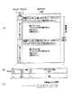
図1は、SDI方式のフレーム構成等を示す図であって、(A)はSDI方式のビデオ信号のフレーム構成を示す図であり、(B)はSDI方式の伝送用パケットの構成を示す図であり、(C)は伝送されるSDI方式のビデオ信号のデータ速度を示す図である。
【0019】
SDI方式のビデオ信号のフレームは、図1(A),(B)に示すように、垂直方向に525(または625)ライン、水平方向に1ライン当たり10ビット×1716(または1728;625ラインモードの場合)ワードの構造になっている。
各ラインにおいて、ラインの第1ワードから第4ワードまでの4ワードは、その前のラインのアクティブビデオ部ACVの終了を示し、水平ブランキング部とを分離する第1分離符号EAV(End of ActiveVideo)として用いられる。
【0020】
第5ワードから第272ワードまでの268ワードは(または第5ワードから第284までの280ワードは)、水平ブランキング部であるが、アンシラリデータ部ANCとして補助データおよび音声データ等を含むこともできる。
第273から第276ワードまで(同じく、または、第284ワードから第288ワードまで)の4ワードは、アクティブビデオ部ACVの開始を示す第2分離符号SAV(Start of Active Video)として用いられる。
第277ワードから第1716ワードまで(同じく、または、第288ワードから1728ワードまで)の1440ワードは、映像信号等を伝送するアクティブビデオ部ACVとして用いられる。
【0021】
また、図1(A)に示すように、垂直方向において、第1ラインから第9ラインまでの9ライン(同じく、または、第1ラインから第24ラインまでの24ライン)は、垂直ブランキング部VBKとして用いられる。
また、525ラインモードの場合のみ、第10ラインから第19ラインまでの10ラインは、オプショナルブランキング部OBKとして用いられる。
第20ラインから第263ラインまでの244ライン(同じく、または、第25ラインから第312ラインまでの288ライン)は、第1フィールドのアクティブビデオ部ACV1 として用いられる。第1フィールドのアクティブビデオ部ACV1 には第1フィールドの映像信号が含まれる。
【0022】
525ラインモードの場合のみ、第264ラインから第272ラインまでの9ライン(または、第313ラインから第337ラインまでの25ライン)は、垂直ブランキング部VBKとして用いられる。
第273ラインから第282ラインまでの10ラインは、オプショナルブランキング部OBKとして用いられる。
第283ラインから第526ラインまでの243ライン(同じく、または、第338ラインから第625ラインまでの288ライン)は、第2フィールドのアクティブビデオ部ACV2 として用いられる。第2フィールドのアクティブビデオ部ACV2 には第2フィールドの映像信号が含まれる。
図1(A),(B)に示したフレーム構成の、10ビットのパラレルのSDI方式のビデオ信号は、図1(C)に示すように、270Mbpsのシリアル形式の伝送信号に変換されてデータ伝送装置1の各構成要素の間で送受信される。
【0023】
以下、図2および図3を参照してSDDI方式の信号フォーマットを説明する。
図2は、SDDI方式のフレーム構成等を示す図であって、(A)はSDDI方式のビデオ信号のフレーム構成を示す図であり、(B)はSDDI方式の伝送用パケットの構成を示す図であり、(C)は伝送されるSDDI方式のビデオ信号のデータ速度を示す図である。
【0024】
図2(A),(B)に示すように、SDDI方式のビデオ信号の各ラインは、SDI方式のビデオ信号の各ラインと同様に、水平方向に1ライン当たり10ビット×1724(または、1716)ワード、垂直方向に525(または、625)ラインで構成されており、図1に示したSDI方式の分離符号SAV,EAV、アンシラリデータ部ANCおよびアクティブビデオ部ACV1 ,ACV2 にそれぞれ相当する第1分離符号EAV、アンシラリデータ部ANC、第2分離符号SAV,およびペイロード部PAD(データ部DT)を含む。
さらに、ペイロード部PADの最後には、アンシラリデータ部ANCの一部およびペイロード部PAD部分の誤り検出および誤り訂正に用いられるCRC符号が付加されている。
ただし、SDDI方式のビデオ信号は、SDI方式のビデオ信号と異なり、アンシラリデータ部ANCに音声データを含まず、ペイロード部分に音声データおよび映像データを含んでいる。
【0025】
なお、図2(A)に示すように、SDDI方式のビデオ信号のフレームには、それぞれ図1に示したSDIビデオ信号の垂直ブランキング部VBKおよびオプショナルブランキング部OBKに対応する部分は含まれていない。
上述した10ビットパラレルのSDDI方式のビデオ信号は、図2(C)に示すように、270Mbpsのシリアル形式の伝送信号に変換されてデータ伝送装置1の各構成要素の間で送受信される。
【0026】
図3は、図2に示したSDDI方式の伝送用パケットのアンシラリデータ部ANCのヘッダ部分に含まれるデータを示す図である。
図3(A),(B)に示すように、SDDI方式の伝送用パケットのアンシラリデータ部ANCは、ヘッダデータHEADERを含み、ヘッダデータHEADERは、先頭に位置している3ワードのヘッダフラグ(000h,3FFh,3FFh)、1ワードのデータID(DATAID)、補助データ領域AUX、宛て先デバイスアドレス(DESTINATION DEVICE ADDRESS)、ソースデバイスアドレス(SOURCE DEVICEADDRESS)およびチェックサム(CHECK SUM)の各データを含んでいる。
上述のヘッダデータHEADERの内、DATAIDは、その伝送用パケットがSDDI方式の伝送用パケットであるか(01h)、SDI用伝送用パケットであるか(00h)を示し、チェックサムは、そのフレームのデータのチェックサムによる誤り検出に用いられる。
宛て先デバイスアドレスおよびソースデバイスアドレスは、その伝送用パケットが伝送される宛て先の装置、および、その伝送用パケットを送出した装置の識別にそれぞれ用いられるデータである。
【0027】第1パラグラフ削除
また、SDI方式のビデオ信号とSDDI方式のビデオ信号の各ラインのデータ長、フレーム構成およびデータ伝送速度は同じにし、さらに、SDI方式の伝送用パケットとSDDI方式の伝送用パケットとに共通性を持たせることにより、送信装置10および受信装置20においては、これらを同等のデータとして取り扱うことができる。
【0028】
SDDI方式の伝送用パケットのヘッダには、ブロックタイプデータ等がさらに含まれており、このブロックタイプデータは、ビデオデータ部DTが含むデータの種別を示す。例えば、ビデオデータ部およびオーディオデータ部に含まれているビデオ信号が圧縮されている場合、その圧縮方法(MPEG等)、ビデオ信号が圧縮されていない場合にはその旨、あるいは、ペイロード部PADにコンピュータ用のデータが含まれている場合にはその旨等を示す。
【0029】
以下、SDI方式の信号とSDDI方式の信号とを同一伝送路を用いて伝送するデータ伝送システム1の構成および動作を説明する。
図4は、第1の実施例における本発明に係るデータ伝送システム1の構成を示す図である。
図4に示すように、データ伝送システム1は送信装置10と受信装置20とから構成されている。
送信装置10は、セレクタ回路(SEL)100、FIFO102,122、パラレル/シリアル変換回路(P/S変換回路)104、制御回路(CPU)110およびシリアル/パラレル変換回路(S/P変換回路)120から構成されている。
受信装置20は、S/P変換回路200、パケット種別データ検出回路(DET)202、FIFO204,220、セレクタ回路(SEL)206、制御回路(CPU)210およびP/S変換回路222から構成されている。
【0030】
制御回路110は、送信装置10に接続される映像機器等の外部から入力される設定データに従って、セレクタ回路100等、送信装置10の各部分を制御する。
セレクタ回路100は、制御回路110の制御に従って、送信装置10の外部から入力されるSDI方式の入力データ(SDIデータ)またはSDDI方式の入力データ(SDDIデータ)を選択し、10ビットパラレル形式の送信信号としてFIFO102に対して出力する。
FIFO102は、セレクタ回路100で選択されて出力されたSDI方式のデータまたはSDDI方式のデータのいずれかの送信信号をバッファリングしてP/S変換回路104に対して出力する。
P/S変換回路104は、10ビットパラレル形式の送信信号(図1(B),図2(B))を1ビットシリアル形式の伝送信号(図1(C),図2(C))に変換して共通の伝送路(SDI/SDDI伝送路)上に送信する。
【0031】
S/P変換回路200は、送信装置10から伝送されてきた伝送信号を受信し、10ビットパラレル形式の受信信号に変換してパケット種別データ検出回路202に対して出力する。
パケット種別データ検出回路202は、受信装置20における受信信号の伝送用パケットの図3(B)に示すアンシラリデータ部ANCに格納されるヘッダデータHEADERのDATAIDの位置の内容が、その伝送用パケットがSDDI方式のものであることを示すパケット識別データ01hであるか否かを検出し、検出結果を制御回路210に対して出力する。また、パケット種別データ検出回路202は、受信信号をそのままFIFO204に対して出力する。さらに、例えばパケット種別データ検出回路202が、タイプデータの内容を判断してタイプ間の違いを検出可能に構成し、タイプ間で異なる制御を行うようにすることも可能である。
制御回路210は、パケット種別データ検出回路202における検出結果等に基づいて、セレクタ回路206等の受信装置20の各部分を制御する。
【0032】
FIFO204は、受信装置20における受信信号をバッファリングしてセレクタ回路206に対して出力する。
セレクタ回路206は、制御回路210の制御に従って、パケット種別データ検出回路202が、その伝送用パケットがSDDI方式のものであることを示すパケット識別データを検出しなかった場合には、受信装置20における受信信号を第1出力端子a側からSDIデータとして出力し、その伝送用パケットがSDDI方式のものであることを示すパケット識別データを検出した場合には、受信装置20における受信信号を第2出力端子b側からSDDIデータとして出力する。
【0033】
また、受信装置20は、FIFO220およびP/S変換回路222により同期信号(REF)を送信装置10に対して送出する。送信装置10は、S/P変換回路120およびFIFO122により同期信号を再生し、制御回路110が同期信号を用いて送信装置10の内部処理等に用いる。この同期信号は、例えば伝送用パケットの送信タイミング等を規定する。
なお、データ伝送システム1において、受信装置20が本発明に係るデータ受信装置に相当し、S/P変換回路200が本発明に係る受信手段に相当し、パケット種別データ検出回路202が本発明に係るパケット種別データ検出手段に相当し、セレクタ回路206が本発明に係るパケット分離手段に相当する。
【0034】
以下、データ伝送システム1の動作を説明する。
送信装置10に、それぞれSDI方式またはSDDI方式に対応する映像機器から入力された10ビットパラレル形式のSDIデータまたはSDDIデータは、送信装置10の外部から入力された設定データに従って制御回路110の制御のもとでセレクタ回路100により選択され、送信信号としてFIFO102に入力される。
FIFO102は、セレクタ回路100から出力される送信信号をバッファリングし、同期信号に同期したタイミングでP/S変換回路104に対して出力する。
P/S変換回路104は、FIFO102から出力される送信信号を1ビットシリアル形式の伝送信号に変換して単一の伝送路を介して受信装置20に対して伝送する。
【0035】
受信装置20のS/P変換回路200は、送信装置10からの伝送信号を受信して10ビットパラレル形式の受信信号に変換してパケット種別データ検出回路202に対して出力する。
パケット種別データ検出回路202は、S/P変換回路200で受信し10ビットパラレル形式の信号に変換した受信信号から伝送用パケットを検出し、図3(B)に示すアンシラリデータ部ANCのヘッダデータHEADERのDATAIDの位置の内容を検出し、その検出結果を制御回路210に対して出力する。
FIFO204は、セレクタ回路206でSDI方式の信号とSDDI方式の信号とを分離して出力する際に、伝送用パケットの頭切れが生じないようにバッファリングしセレクタ回路206に対して出力する。
セレクタ回路206は、伝送用パケットの図3(B)に示すアンシラリデータ部ANCのヘッダデータHEADERのDATAIDの内容、すなわち、SDDI方式か否かに応じた制御回路210の制御に従って、SDIデータとSDDIデータを分離して第1または第2の出力端子a、bから出力する。
【0036】
データ伝送システム1によれば、SDIデータとSDDIデータとを同一伝送路上で伝送することができる。従って、図7を参照して例示した従来例として示したデータ伝送装置8において、送信装置および受信装置においてそれぞれ、2組必要であったFIFO812、822、FIFO840、850、P/S変換回路810、820およびS/P変換回路842、852を1組に減らすことができるので、装置コストが低い。
また、データ伝送システム1によれば、従来2本必要であった伝送路を1本に減らすことができるので、伝送路のコストを減らすことができ、敷設工事も簡単になる。
また、データ伝送システム1によれば、受信装置20側において自動的にSDI方式とSDDI方式の伝送用パケットを識別してこれらを分離可能なので、SDI方式対応の映像機器とSDDI方式の映像機器とを同一の映像処理システム内に混在させやすい。
【0037】
【実施例2】
以下、本発明の第2の実施例を説明する。
図5は、第2の実施例における本発明に係るデータ伝送システム3の構成を示す図である。
図6は、図5に示したデータ送受信装置32a〜32dの構成を示す図である。
図5に示すように、本発明に係るデータ伝送システム3は、4個のデータ送受信装置32a〜32dから構成されており、データ送受信装置32a〜32d相互間でSDI方式の信号とSDDI方式の信号とを同一伝送路上に混在させて伝送するように構成されている。
【0038】
データ送受信装置32a〜32dは同一の構成であり、同一のおよび動作を行う。
図6に示すように、データ送受信装置32a〜32d(以下、これらを別個に特定しない場合には、単にデータ送受信装置32と記す)は、それぞれS/P変換回路320,350、P/S変換回路344,362、パケット種別データ検出回路322、FIFO324,340,352,360、制御回路(CPU)330およびスイッチネットワーク332から構成されており、それぞれ他のデータ送受信装置32から送られてきた伝送信号から、それぞれに接続された映像機器に応じてSDIデータまたはSDDIデータを分離して信号VOUTa〜VOUTdとして供給し、あるいは、他のデータ送受信装置32に対して映像機器からの入力信号VINa〜VINdを送信し、あるいは、伝送信号を中継する。
【0039】
S/P変換回路320は、図4に示したS/P変換回路200と同様の動作を行い、他のデータ送受信装置32から伝送されてきた伝送信号を受信し、パラレル形式の受信信号に変換してパケット種別データ検出回路322に対して出力する。
パケット種別データ検出回路322は、図4に図解したパケット種別データ検出回路202と同様の動作を行い、受信信号のパケット識別データを検出し、検出結果を制御回路330に対して、受信信号をそのままFIFO324に対して出力する。
【0040】
FIFO324は、図4に図解したFIFO204と同様の動作を行い、受信信号をバッファリングしてスイッチネットワーク332に対して出力する。
FIFO340は、図4に図解したFIFO102と同様の動作を行い、スイッチネットワーク332から入力された送信信号をバッファリングしてP/S変換回路344に対して出力する。
制御回路330は、図4に図解した制御回路110および制御回路210と同様の動作を行い、データ送受信装置32それぞれに接続される映像機器等の外部から入力される設定データに従って、スイッチネットワーク332等の各部分を制御する。
【0041】
S/P変換回路350およびFIFO352は、図4に図解したS/P変換回路120およびFIFO122と同様の動作を行い、他のデータ送受信装置32からの同期信号を受信する。
FIFO360およびP/S変換回路362は、図4に図解したFIFO220およびP/S変換回路222と同様の動作を行い、他のデータ送受信装置32に対して同期信号を送信する。
【0042】
スイッチネットワーク332は、入力端子a,cと出力端子b,d間の信号切替えを行う。具体的には、スイッチネットワーク332は、制御回路330の制御に従って、映像機器から入力端子cに入力されたSDI方式またはSDDI方式の入力信号VINa〜VINdを出力端子bから送信信号として出力し、入力端子aから入力された受信信号からSDIデータまたはSDDIデータを分離して出力端子dから出力信号VOUTa〜VOUTdとして出力し、さらに、入力端子aから入力された伝送信号をそのまま出力端子bから送信信号として出力する。
【0043】
以下、図5および図6に示したデータ伝送システム3およびデータ送受信装置32の動作を説明する。
データ伝送システム3においては、伝送信号はデータ送受信装置32aからデータ送受信装置32bへ、データ送受信装置32bからデータ送受信装置32cへといったように伝送される。
データ送受信装置32a〜32dは、それぞれ接続された映像機器に対応するSDIデータまたはSDDIデータを図4に示した受信装置20と同様に伝送信号から取り出して供給するとともに、取り出さなかった伝送信号を次のデータ送受信装置32に対して中継する。
また、データ送受信装置32a〜32dの間では、図5に示すように同期信号REFの送受信も行われる。
【0044】
データ伝送システム3をこのように構成することにより、SDI方式対応の映像機器とSDDI方式対応の映像機器とを混在させて大規模な映像処理システムを容易に構成することができる上、第1の実施例に示したデータ伝送システム1と同様な効果を得ることができる。
【0045】
なお、データ送受信装置32は4台に限らず、任意の台数でデータ伝送システム3を構成することができる。また、接続関係も図5に示したものに限らず、例えばデータ送受信装置32が複数の伝送路を介してデータの送受信が可能なように構成して、データ送受信装置32a,32cおよびデータ送受信装置32b,32d間を直接接続する伝送路を設けてもよい。
データ送受信装置32に、図3(B)に図解したアンシラリデータ部ANCに格納されるヘッダデータHEADERのうちの宛て先デバイスアドレス(DESTINATION DEVICE ADDRESS)を検出する機能を追加することにより、任意のデータを所望の機器に対して伝送することができる映像処理システムを実現することも可能である。
また、このような機能を追加するとともに、データ送受信装置32に交換機能を付加し、さらに複雑なシステムを構成可能にしてもよい。
【0046】
以上、本発明のデータ受信装置、および、データ送受信装置、および、これらの方法について実施の形態を述べたが、上述した構成および機能を映像機器に適用することができる。
また上述した方法を映像機器に適用する映像信号処理方法も提供できる。
【0047】
【発明の効果】
以上述べたように本発明に係るデータ受信装置、データ送受信装置、映像機器、およびこれらの方法によれば、SDI方式対応の映像機器とSDDI方式対応の映像機器とが混在する映像処理システムにおいて、これらの映像機器相互間で同一伝送路上にSDI方式の信号とSDDI方式の信号とを混在させて送受信させることができる。
【0048】
また、本発明に係るデータ受信装置、データ送受信装置、映像機器、およびこれらの方法によれば、同一伝送路上を伝送されてきたSDI方式の信号とSDDI方式の信号とを自動的に識別し、伝送用パケット単位で分離して、それぞれ対応する映像機器に供給することが可能である。
【図面の簡単な説明】
【図1】SDI方式のフレーム構成等を示す図であって、(A)はSDI方式のビデオ信号のフレーム構成を示す図であり、(B)はSDI方式の伝送用パケットの構成を示す図であり、(C)は伝送されるSDI方式のビデオ信号のデータ速度を示す図である。
【図2】SDDI方式のフレーム構成等を示す図であって、(A)はSDDI方式のビデオ信号のフレーム構成を示す図であり、(B)はSDDI方式の伝送用パケットの構成を示す図であり、(C)は伝送されるSDDI方式のビデオ信号のデータ速度を示す図である。
【図3】図2に示したSDDI方式の伝送用パケットのアンシラリデータ部ANCに含まれるデータを示す図である。
【図4】第1の実施例における本発明に係るデータ伝送システムの構成を示す図である。
【図5】第2の実施例における本発明に係るデータ伝送システムの構成を示す図である。
【図6】図5に示したデータ送受信装置の構成を示す図である。
【図7】従来のデータ伝送装置の構成を示す図である。
【符号の説明】
1,3…データ伝送システム、10…送信装置、20…受信装置、32,32a〜32d…データ送受信装置、100,206…セレクタ回路、102,122,204,220,324,340,352,360…FIFO、104,222,344,362…P/S変換回路、120,200,320,350…S/P変換回路、202,332…パケット種別データ検出回路、110,210,330…制御回路、332…スイッチネットワーク[0001]
[Industrial applications]
The present invention relates to a data receiving apparatus, a data transmitting / receiving apparatus, a video device, and a data transmission system using the same, which are used for transmitting a plurality of transmission packets on the same transmission path., Video signal processing system, andRegarding these methods.
[0002]
[Prior art]
2. Description of the Related Art A serial digital interface (SDI) system has been conventionally used as a system for transmitting a digital video signal (hereinafter simply referred to as a video signal) or the like between devices used for video editing or the like. The signal format of the SDI system is standardized as SMPTE-295M of SMPTE (Society of Motion Picture and Television Engineerings) as a standard of digital video and audio signals.
The SDI system is used for transmitting digital video signals of the D1 system and the D2 system, and its transmission speed is as high as 270 MHz.
[0003]
However, the SDI method is limited to a signal that can be transmitted only for one channel of a video signal and only eight channels for a baseband audio signal. Not always suitable for responding to channeling needs.
For this reason, an SDDI scheme that is more compatible with multimedia has been proposed so that variable-length video signal data can be transmitted while having considerable compatibility with the SDI scheme.
[0004]
In order to transmit the SDI signal and the SDDI signal, the
The
[0005]
Also, the
[0006]
The synchronization signal that defines the timing of signal transmission between the
[0007]
[Problems to be solved by the invention]
Here, there is a demand for transmitting the SDI signal and the SDDI signal using the same transmission line for the reason of reducing the number of transmission lines and simplifying the laying work of the transmission line. However, while the SDI signal contains only fixed-length data, the SDDI signal sometimes contains variable-length data in addition to fixed-length data. Therefore, if these signals are transmitted using the same transmission path,In the data receiving device ofIt is necessary to separate the signals of the SDI system and the signals of the SDDI system and supply them to a video editing device or the like corresponding to the signal of each system.
[0008]
SUMMARY OF THE INVENTION The present invention has been made in view of the above-described problems of the related art, and in a video processing system in which video equipment compatible with the SDI system and video equipment compatible with the SDDI system coexist, the same video equipment is used. A data receiving apparatus, a data transmitting / receiving apparatus, which can mix and transmit an SDI signal and an SDDI signal on a transmission path;Video equipmentAnd data transmission system using them, Video signal processing system, and these methodsAbout.
Further, the present invention can automatically identify an SDI signal and an SDDI signal transmitted on the same transmission path, separate them in transmission packet units, and supply them to corresponding video equipment. Possible data receiving device, data transmitting and receiving device,Video equipmentAnd data transmission system using them, Video signal processing system, and these methodsThe purpose is to provide.
[0009]
[Means for Solving the Problems]
According to a first aspect of the present invention,
Receiving the first data of the SDI system and the second data of the SDDI system having different frame configurations transmitted through a single transmission path, and identifying the received first data or second data for each packet; A data receiving device for separating and outputting to a different first data output terminal or a different second data output terminal,
The first data of the SDI system includes a first vertical blanking unit, a data storage unit for the first field, a second vertical blanking unit, and a data for the second field along the vertical direction of the video signal. Each of the lines for the first and second fields includes an end synchronization code area, an ancillary data area, a start code area, and an active video area. A synchronization code indicating the end of the active video area of the previous line is stored, the ancillary data area stores data indicating the type of the first data, and the start code area includes the active video area. Are stored, and a fixed-length video signal is stored in the active video area.
In the second data of the SDDI system, each line along the vertical direction of the video signal includes an end synchronization code area, an ancillary data area, a start code area, and a payload area. Stores a synchronization code indicating the end of the payload area of the previous line, stores data indicating the type of the second data in the ancillary data area, and stores the payload area in the start code area. A synchronization code is stored in the payload area, and a fixed-length or variable-length video signal is stored in the payload area.
The data indicating the type of the first data in the ancillary data area of the first data is the same as the data indicating the type of the second data in the ancillary data area of the second data,
The data receiving device,
Serial-parallel conversion means for converting the first data or the second data in a serial format input through the single transmission path into parallel data;
Referring to the data indicating the data type of the ancillary data area of the parallel format data converted by the conversion means, it is determined that one of the first and second data has been input. Packet identification data detection means for detecting in packet units,
Data buffering means for buffering and outputting the input first data or second data in packet units;
Control means;
A first input terminal and first and second output terminals for receiving packet-based data read from the data buffering unit from the first input terminal under the control of the control unit; Data selection output means for selectively outputting from the first data output terminal or the second data output terminal according to the data type detected by the data detection means;
Is provided.
[0010]
According to a second aspect of the present invention, there is provided a data receiving method for performing the processing of the data receiving device.
According to a third aspect of the present invention, there is provided a video device having the above data receiving device.
According to a fourth aspect of the present invention, there is provided a video processing method performed by the video device.
[0011]
According to a fifth aspect of the present invention,
A data transmission device and a data reception device connected via a single data transmission path, and the SDI system having a different frame configuration from the transmission device to the data reception device via the single transmission line. 1 data and 2nd data of the SDDI system are transmitted, and the received 1st data or 2nd data is identified for each packet in the data receiving device and separated into different 1st data output terminals or 2nd data output terminals. A data transmitting and receiving device,
The first data of the SDI system includes a first vertical blanking unit, a data storage unit for the first field, a second vertical blanking unit, and a data for the second field along the vertical direction of the video signal. Each of the lines for the first and second fields includes an end synchronization code area, an ancillary data area, a start code area, and an active video area. A synchronization code indicating the end of the active video area of the previous line is stored, the ancillary data area stores data indicating the type of the first data, and the start code area includes the active video area. Are stored, and a fixed-length video signal is stored in the active video area.
In the second data of the SDDI system, each line along the vertical direction of the video signal includes an end synchronization code area, an ancillary data area, a start code area, and a payload area. Stores a synchronization code indicating the end of the payload area of the previous line, stores data indicating the type of the second data in the ancillary data area, and stores the payload area in the start code area. A synchronization code is stored in the payload area, and a fixed-length or variable-length video signal is stored in the payload area.
The data indicating the type of the first data in the ancillary data area of the first data is the same as the data indicating the type of the second data in the ancillary data area of the second data,
The transmitting device,
Data input selection means for selecting and inputting either the first data in the parallel format or the second data in the parallel format based on the setting data;
First buffering means for buffering and holding output data from the data input selecting means;
Data sending means for converting the data held in the first buffering means into serial data and sending the serial data to the data receiving device via the single transmission path;
A first control unit for controlling operation timings of the data input selection unit, the first buffering unit, and the data transmission unit based on a synchronization signal transmitted from the data reception device;
Has,
The data receiving device,
Serial-parallel conversion means for converting the first data or the second data in a serial format input through the single transmission path into parallel data;
Reference is made to data indicating the data type of the ancillary data area of the parallel format data converted by the serial / parallel conversion means, and it is detected on a packet basis that either the first or second data has been input. Packet identification data detection means;
Second buffering means for buffering and outputting the input first data or second data in packet units;
Control means;
A first input terminal and first and second output terminals, receiving data in packet units read from the data buffering means from the first input terminal under the control of the control means; Data selection output means for selectively outputting from the first data output terminal or the second data output terminal according to the data type detected by the data detection means;
Synchronization signal sending means for sending the synchronization signal to the data transmission device;
Having,
A data transmitting / receiving device is provided.
[0012]
According to a sixth aspect of the present invention, there is provided a data receiving method performed by the data transmitting / receiving apparatus.
According to a seventh aspect of the present invention, there is provided a video device having the above data transmitting / receiving device.
According to an eighth aspect of the present invention, there is provided a video signal method performed by the video device.
[0013]
According to a ninth aspect of the present invention,
It has a pair of video devices connected via a single data transmission path, and the first video device of the SDI system having a different frame configuration from the one video device to the other video device via the single transmission line. The data and the second data of the SDDI system are transmitted, and the other video equipment separates the received first data or second data for each packet and separates the received first data or second data into different first data output terminals or second data output terminals. Output, a video signal processing system,
The first data of the SDI system includes a first vertical blanking unit, a data storage unit for the first field, a second vertical blanking unit, and a data for the second field along the vertical direction of the video signal. Each of the lines for the first and second fields includes an end synchronization code area, an ancillary data area, a start code area, and an active video area. A synchronization code indicating the end of the active video area of the previous line is stored, the ancillary data area stores data indicating the type of the first data, and the start code area includes the active video area. Are stored, and a fixed-length video signal is stored in the active video area.
In the second data of the SDDI system, each line along the vertical direction of the video signal includes an end synchronization code area, an ancillary data area, a start code area, and a payload area. Stores a synchronization code indicating the end of the payload area of the previous line, stores data indicating the type of the second data in the ancillary data area, and stores the payload area in the start code area. A synchronization code is stored in the payload area, and a fixed-length or variable-length video signal is stored in the payload area.
The data indicating the type of the first data in the ancillary data area of the first data is the same as the data indicating the type of the second data in the ancillary data area of the second data,
Each of the video devices,
A transmission unit;
A receiving unit,
A data input / output selection unit having first and second input terminals and first and second output terminals, wherein the second input terminal and the second output terminal are connected to a video device;
Control means and
Has,
The data input / output selection unit is configured to output either the first data in parallel format or the second data in parallel format input to the first input terminal under the control of the control means to the first output terminal or Outputting to the second output terminal, and outputting data input from the second input terminal to the second output terminal;
The transmitting unit includes:
First buffering means for buffering and holding data output from a first output terminal of the data input / output selection unit;
Data transmitting means for converting the data held in the first buffering means into serial data and transmitting the serial data to a receiving unit of a video device connected via the transmission path;
Has,
The data receiving unit,
A receiving unit that receives the first data or the second data from a transmission unit of a video device connected via the transmission path and converts the data into a parallel format;
Packet type data detection means for identifying data indicating the data type included in the received first data or second data in packet units;
Second buffering means for buffering and outputting the received first data or second data,
Synchronizing signal transmitting means for transmitting the synchronizing signal to a transmitting unit of a video device connected via the transmission path;
Has,
The control unit controls the operation timing of the data input / output selection unit, the reception unit, and the transmission unit based on a synchronization signal transmitted from a data reception unit of a video device connected via the transmission path,
The data receiving unit converts the packet data read from the second buffering unit into a first data output terminal or a second data output terminal of the data input / output selection unit according to a data type detected by the packet identification data detection unit. Output according to the data type from
An image signal processing system is provided.
[0014]
According to a tenth aspect of the present invention, there is provided a video signal processing method performed by the video signal processing system.
[0015]
[Action]
Second dataIsFor example,A packet for transmission used in the SDDI system, and a predetermined position of a control portion of the transmission packet includes packet type data indicating that the transmission packet is in the SDDI system. By doing so, it is possible to identify that the packet is the first data. In the data portion of the first data, a mixture of fixed length data and variable length data is allowed.
[0016]
First dataIsFor example,A transmission packet used for the SDI method,First dataDoes not include the packet type data of the transmission packet of the SDDI system, but includes only the fixed length data in the data portion.
The receiving means receives the serial transmission signal from the transmission path and converts the transmission signal into a parallel signal which can be easily processed by, for example, serial / parallel conversion.
[0017]
The packet type data detecting unit detects, for example, the position of the position indicated by the synchronization signal in the signal received by the receiving unit and converted into a parallel format signal.For example,The packet type data of the SDDI system is detected.
The data selection output meansFor example,A transmission packet including the packet type data of the SDDI method is used as the second data.SecondA packet for transmission that is output from the output terminal and does not include the packet type data of the SDDI methodFirst dataAsFirstThese are output from an output terminal and are separated and output.
[0018]
Embodiment 1
Hereinafter, a first embodiment of the present invention will be described.
First, prior to description of the data transmission system 1 (FIG. 4) according to the present invention, referring to FIGS.Data transmission system 1The signal formats of the SDI system and the SDDI system used as the transmission system of the transmission signal received by the STA will be described.
1A and 1B are diagrams showing a frame configuration of the SDI system and the like. FIG. 1A is a diagram showing a frame configuration of an SDI system video signal, and FIG. 1B is a diagram showing a configuration of an SDI system transmission packet. (C) is a diagram showing the data rate of the transmitted SDI video signal.
[0019]
As shown in FIGS. 1A and 1B, the frame of the SDI video signal is 525 (vertically).Or625) lines, 10 bits per line in the horizontal direction × 1716 (Or1728; 625 line mode) has a word structure.
In each line, four words from the first word to the fourth word of the line are:Before thatIndicates the end of the active video section ACV of the line and separates it from the horizontal blanking sectionFirstIt is used as a separation code EAV (End of Active Video).
[0020]
268 words from the 5th word to the 272nd wordIs (or280 words from the 5th word to the 284th wordIs), Horizontal blanking section, but the ancillary data section ANC may include auxiliary data and audio data.
From the 273rd to the 276th word (also,OrThe four words (from the 284th word to the 288th word) indicate the start of the active video section ACV.SecondIt is used as a separation code SAV (Start of Active Video).
From the 277th word to the 1716th word (also,Or1440 words (from the 288th word to 1728 words) are used as an active video unit ACV for transmitting a video signal or the like.
[0021]
Also, as shown in FIG. 1A, in the vertical direction, nine lines from a first line to a ninth line (similarly,Or24 lines from the first line to the 24th line) are used as the vertical blanking unit VBK.
Also, only in the 525-line mode, ten lines from the tenth line to the nineteenth line are used as the optional blanking unit OBK.
244 lines from
[0022]
Only in the case of the 525-line mode, 9 lines from line 264 to line 272 (OrLine 313 to line 337 (25 lines) are used as the vertical blanking unit VBK.
The tenth line from the 273rd line to the 282nd line is used as an optional blanking unit OBK.
243 lines from line 283 to line 526 (also,OrThe 288th line from the 338th line to the 625th line) is used as the active video section ACV2 of the second field. The active video part ACV2 of the second field contains the video signal of the second field.
In the frame configuration shown in FIGS.10 bit parallelThe SDI video signal is converted into a 270 Mbps serial transmission signal and transmitted and received between the components of the data transmission apparatus 1 as shown in FIG.
[0023]
Hereinafter, the signal format of the SDDI system will be described with reference to FIGS.
2A and 2B are diagrams illustrating a frame configuration of the SDDI system, and FIG. 2A is a diagram illustrating a frame configuration of a video signal of the SDDI system, and FIG. 2B is a diagram illustrating a configuration of a transmission packet of the SDDI system. (C) is a diagram showing the data rate of the transmitted SDDI video signal.
[0024]
As shown in FIGS. 2A and 2B, each line of the SDDI video signal is 10 bits × 1724 (10 bits per line) in the horizontal direction similarly to each line of the SDI video signal.Or1716) words, 525 verticallyOr625), and corresponds to the SDI separation codes SAV and EAV, ancillary data section ANC, and active video sections ACV1 and ACV2 shown in FIG.FirstSeparatorNo. EAV, ancillary data section ANC,Second separation code SAV, And a payload portion PAD (data portion DT).
Further, a CRC code used for error detection and error correction of a part of the ancillary data part ANC and the payload part PAD is added to the end of the payload part PAD.
However, unlike the SDI video signal, the SDDI video signal is different from the ancillary data part AN.To CIt does not include audio data, but includes audio data and video data in the payload portion.
[0025]
As shown in FIG. 2A, the frame of the SDDI video signal includes portions corresponding to the vertical blanking section VBK and the optional blanking section OBK of the SDI video signal shown in FIG. 1, respectively. Not.
Mentioned above10 bit parallelThe SDDI video signal is converted into a 270 Mbps serial transmission signal and transmitted and received between the components of the data transmission apparatus 1 as shown in FIG. 2C.
[0026]
FIG. 3 is a diagram showing data included in the header part of the ancillary data part ANC of the transmission packet of the SDDI system shown in FIG.
As shown in FIGS. 3A and 3B, the ancillary data portion ANC of the SDDI transmission packet is used.Includes the header data HEADER, and the header data HEADER isLocated on the head3Word header flags (000h, 3FFh, 3FFh), 1-word data ID (DATAID),Auxiliary data area AUX,addressdeviceAddress (DESTINATIONDEVICEADDRESS), sourcedeviceThe data includes an address (SOURCE DEVICE ADDRESS) and a checksum (CHECK SUM).
Header data described aboveHEADERAmong them, DATAID indicates whether the transmission packet is an SDDI transmission packet (01h) or an SDI transmission packet (00h), and the checksum is based on the checksum of the data of the frame. Used for error detection.
addressdeviceAddress and sourcedeviceThe address is data used to identify a destination device to which the transmission packet is transmitted and a device that has transmitted the transmission packet.
First paragraph deleted
The data length, frame configuration and data transmission speed of each line of the SDI video signal and the SDDI video signal are the same, and the SDI transmission packet and the SDDI transmission packet have commonality. By
[0028]
The header of the transmission packet of the SDDI system further includes block type data and the like, and the block type data includes a video data portion.DTIndicates the type of data included in. For example, when the video signal included in the video data section and the audio data section is compressed, the compression method (MPEG or the like) is used. When the video signal is not compressed, the fact is described. If data for a computer is included, this is indicated.
[0029]
Hereinafter, the configuration and operation of the data transmission system 1 that transmits an SDI signal and an SDDI signal using the same transmission path will be described.
FIG. 4 is a diagram showing the configuration of the data transmission system 1 according to the first embodiment of the present invention.
As shown in FIG. 4, the data transmission system 1 includes a transmitting
The
The receiving
[0030]
The control circuit 110 controls each part of the
The
The P /
[0031]
The S /
The packet type data detection circuit 202In the receiving device 20FIG. 3B shows a packet for transmitting a received signal.Of header data HEADER stored in ancillary data section ANCIt detects whether or not the content of the position of DATAID is packet identification data 01h indicating that the transmission packet is of the SDDI system, and outputs the detection result to control
The
[0032]
FIFO 204In the receiving device 20The received signal is buffered and output to the selector circuit 206.
When the packet type
[0033]
Further, the receiving
In the data transmission system 1, the receiving
[0034]
Hereinafter, the operation of the data transmission system 1 will be described.
The SDI data or SDDI data in the 10-bit parallel format input from the video device corresponding to the SDI system or the SDDI system to the transmitting
The P / S conversion circuit 104Output from FIFO 102Convert the transmission signal to a 1-bit serial transmission signalsingleThe signal is transmitted to the receiving
[0035]
Of the receiving device 20The S / P conversion circuit 200From the transmitting device 10The transmission signal is received, converted into a 10-bit parallel reception signal, and output to the packet type
The packet type data detection circuit 202The signal was received by the S /
The
The selector circuit 206 shown in FIG.Ancillary data section ANC header data HEADERContent of DATAIDIn other words, whether or not the SDDI methodThe SDI data and the SDDI data are separated according to the control of the corresponding control circuit 210.From the first or second output terminals a, bOutput.
[0036]
According to the data transmission system 1, SDI data and SDDI data can be transmitted on the same transmission path. Therefore,Illustrated with reference to FIG.In the
Further, according to the data transmission system 1, the number of transmission lines conventionally required two can be reduced to one, so that the cost of the transmission lines can be reduced and the installation work can be simplified.
Further, according to the data transmission system 1, the receiving
[0037]
Embodiment 2
Hereinafter, a second embodiment of the present invention will be described.
FIG. 5 is a diagram showing the configuration of the
FIG. 6 is a diagram showing a configuration of the data transmission /
As shown in FIG. 5, the
[0038]
The data transmission /
As shown in FIG. 6, the data transmission /
[0039]
The S /
The packet type data detection circuit 322 includes:Illustrated in FIG.The same operation as the packet type
[0040]
The control circuit 330Illustrated in FIG.Control circuit
[0041]
The S /
The
[0042]
The switch network 332 performs signal switching between input terminals a and c and output terminals b and d. Specifically, the switch network 332 outputs the SDI or SDDI input signals VINa to VINd input from the video equipment to the input terminal c as transmission signals from the output terminal b under the control of the
[0043]
Hereinafter, operations of the
In the
The data transmission /
Further, transmission and reception of the synchronization signal REF are also performed between the data transmitting / receiving
[0044]
By configuring the
[0045]
The number of the data transmitting / receiving devices 32 is not limited to four, and the
To the data transmitting / receiving device 32And a destination device address (DESTINATION DEVICE ADDRESS) of the header data HEADER stored in the ancillary data section ANC illustrated in FIG. 3B.By adding a function of detecting an image, a video processing system capable of transmitting arbitrary data to a desired device can be realized.
Further, in addition to such a function, an exchange function may be added to the data transmission / reception device 32 so that a more complicated system can be configured.
[0046]
As described above, the embodiments of the data receiving apparatus, the data transmitting / receiving apparatus, and the methods of the present invention have been described.
Further, a video signal processing method in which the above method is applied to a video device can be provided.
[0047]
【The invention's effect】
As described above, according to the data receiving device, the data transmitting / receiving device, the video device, and the method according to the present invention, in the video processing system in which the SDI video device and the SDDI video device are mixed, The SDI signal and the SDDI signal can be mixed and transmitted and received on the same transmission path between these video devices.
[0048]
Further, according to the data receiving apparatus, the data transmitting / receiving apparatus, the video equipment, and the methods according to the present invention, the SDI signal and the SDDI signal transmitted on the same transmission path are automatically identified, It is possible to separate them into transmission packet units and supply them to the corresponding video equipment.
[Brief description of the drawings]
FIGS. 1A and 1B are diagrams showing a frame structure of an SDI system and the like, wherein FIG. 1A is a diagram showing a frame structure of an SDI system video signal, and FIG. 1B is a diagram showing a structure of an SDI system transmission packet; (C) is a diagram showing the data rate of the transmitted SDI video signal.
FIGS. 2A and 2B are diagrams showing a frame configuration and the like of the SDDI system, wherein FIG. 2A is a diagram showing a frame configuration of an SDDI video signal, and FIG. 2B is a diagram showing a configuration of a transmission packet of the SDDI system; (C) is a diagram showing the data rate of the SDDI video signal transmitted.
FIG. 3 is a diagram showing data included in an ancillary data part ANC of the transmission packet of the SDDI system shown in FIG. 2;
FIG. 4 is a diagram showing a configuration of a data transmission system according to the present invention in the first embodiment.
FIG. 5 is a diagram showing a configuration of a data transmission system according to the present invention in a second embodiment.
FIG. 6 is a diagram showing a configuration of the data transmitting / receiving device shown in FIG.
FIG. 7 is a diagram showing a configuration of a conventional data transmission device.
[Explanation of symbols]
1, 3 data transmission system, 10 transmission device, 20 reception device, 32, 32a to 32d data transmission / reception device, 100, 206 selector circuit, 102, 122, 204, 220, 324, 340, 352, 360 ... FIFO, 104, 222, 344, 362 ... P / S conversion circuit, 120, 200, 320, 350 ... S / P conversion circuit, 202, 332 ... packet type data detection circuit, 110, 210, 330 ... control circuit, 332 ... Switch network
Claims (16)
前記SDI方式の第1データは、映像信号の垂直方向に沿って、第1垂直ブランキング部と、第1フィールド分のデータ格納部と、第2垂直ブランキング部と、第2フィールド分のデータ格納部とを有し、第1および第2フィールド分の各ラインは、終了同期符号領域と、アンシラリデータ領域と、開始符号領域と、アクティブビデオ領域とからなり、前記終了同期符号領域には前ラインのアクティブビデオ領域の終了を示す同期符号が格納されており、前記アンシラリデータ領域には当該第1データの種別を示すデータが格納されており、前記開始符号領域には前記アクティブビデオ領域を示す同期符号が格納されており、前記アクティブビデオ領域には固定長の映像信号が格納されており、
前記SDDI方式の第2データは、映像信号の垂直方向に沿って各ラインが、終了同期符号領域と、アンシラリデータ領域と、開始符号領域と、ペイロード領域とからなり、前記終了同期符号領域には前ラインのペイロード領域の終了を示す同期符号が格納されており、前記アンシラリデータ領域には当該第2データの種別を示すデータが格納されており、前記開始符号領域には前記ペイロード領域を示す同期符号が格納されており、前記ペイロード領域には固定長または可変長の映像信号が格納されており、
前記第1データのアンシラリデータ領域の第1データの種別を示すデータと第2データのアンシラリデータ領域の第2データの種別を示すデータとは同じ位置であり、
当該データ受信装置は、
前記単一の伝送路を介して入力されたシリアル形式の前記第1データまたは前記第2データをパラレルデータに変換するシリアル・パラレル変換手段と、
前記変換手段で変換されたパラレル形式のデータの前記アンシラリデータ領域のデータ種別を示すデータを参照して第1または第2データのいずれかが入力されたことをパケット単位で検出するパケット識別データ検出手段と、
前記入力した第1データまたは第2データをパケット単位でバッファリングして出力するデータバッファリング手段と、
制御手段と、
第1入力端子および第1および第2出力端子を有し、前記制御手段の制御のもとで、前記データバッファリング手段から読み出したパケット単位のデータを前記第1入力端子から受け入れ、前記パケット識別データ検出手段で検出したデータ種別に応じて前記第1データ出力端子または前記第2データ出力端子から選択的に出力するデータ選択出力手段と
を有するデータ受信装置。Receiving the first data of the SDI system and the second data of the SDDI system having different frame configurations transmitted through a single transmission path, and identifying the received first data or second data for each packet; A data receiving device for separating and outputting to a different first data output terminal or a different second data output terminal,
The first data of the SDI system includes a first vertical blanking unit, a data storage unit for the first field, a second vertical blanking unit, and a data for the second field along the vertical direction of the video signal. Each of the lines for the first and second fields includes an end synchronization code area, an ancillary data area, a start code area, and an active video area. A synchronization code indicating the end of the active video area of the previous line is stored, the ancillary data area stores data indicating the type of the first data, and the start code area includes the active video area. Are stored, and a fixed-length video signal is stored in the active video area.
In the second data of the SDDI system, each line along the vertical direction of the video signal includes an end synchronization code area, an ancillary data area, a start code area, and a payload area. Stores a synchronization code indicating the end of the payload area of the previous line, stores data indicating the type of the second data in the ancillary data area, and stores the payload area in the start code area. A synchronization code is stored in the payload area, and a fixed-length or variable-length video signal is stored in the payload area.
The data indicating the type of the first data in the ancillary data area of the first data is the same as the data indicating the type of the second data in the ancillary data area of the second data,
The data receiving device,
Serial-parallel conversion means for converting the first data or the second data in a serial format input through the single transmission line into parallel data;
Packet identification data for detecting, in packet units, that either the first or second data has been input by referring to data indicating the data type of the ancillary data area of the parallel format data converted by the conversion means Detecting means;
Data buffering means for buffering and outputting the input first data or second data in packet units;
Control means;
A first input terminal and first and second output terminals for receiving packet-based data read from the data buffering unit from the first input terminal under the control of the control unit; A data receiving device comprising: a data selection output means for selectively outputting from the first data output terminal or the second data output terminal according to a data type detected by data detection means.
当該データ受信装置はさらに、
前記第3出力端子から出力された前記パラレル形式の第1データおよび第2データが入力され、これら入力されたパラレル形式の第1データおよび第2データをシリアル形式の第1データおよび第2データに変換して出力するパラレル・シリアル変換手段と、
前記データ選択出力手段から、前記パケット識別データ検出手段の検出結果を示すデータおよび設定された設定データに基づいて前記第1データおよび第2データを前記データ選択出力手段の第1出力端子または第2出力端子、または、前記第1データおよび前記第2データを前記データ選択出力手段の第3出力端子に選択的に出力させるように制御する制御手段と
をさらに有し、
前記パラレル・シリアル変換手段から出力された前記シリアル形式の第1データまたは第2データが前記データ選択出力手段の第3出力端子から出力することを特徴とする、
請求項1記載のデータ受信装置。The data selection output means further has a third output terminal for outputting the first data and the second data in the parallel format,
The data receiving device further includes:
The first data and the second data in the parallel format output from the third output terminal are input, and the input first data and the second data in the parallel format are converted into the first data and the second data in the serial format. Parallel-serial conversion means for converting and outputting;
The data selection and output unit outputs the first data and the second data based on the data indicating the detection result of the packet identification data detection unit and the set data, to a first output terminal or a second output terminal of the data selection and output unit. An output terminal or control means for controlling the first data and the second data to be selectively output to a third output terminal of the data selection output means,
The first data or the second data in the serial format output from the parallel-serial conversion means is output from a third output terminal of the data selection output means.
The data receiving device according to claim 1.
前記制御手段は、前記パケット識別データ検出手段の検出結果を示すデータと前記設定されたデータに基づいて前記シリアル・パラレル変換手段から出力された前記パラレル形式の第1データまたは第2データ、または、前記データ選択出力手段の第1入力端子より入力されたパラレル形式の第1データまたは第2データを、前記データ選択出力手段の第3出力端子から選択的に出力させるよう前記データ選択出力手段を制御する
請求項2に記載のデータ受信装置。The data selection output means further has a second input terminal to which first data and second data in parallel format output from an external device located outside the data receiving device are input,
The control means, the first data or the second data in the parallel format output from the serial-parallel conversion means based on the data indicating the detection result of the packet identification data detection means and the set data, or The data selection / output means is controlled to selectively output the first data or the second data in the parallel format inputted from the first input terminal of the data selection / output means from the third output terminal of the data selection / output means. The data receiving apparatus according to claim 2, wherein
前記SDI方式の第1データは、映像信号の垂直方向に沿って、第1垂直ブランキング部と、第1フィールド分のデータ格納部と、第2垂直ブランキング部と、第2フィールド分のデータ格納部とを有し、第1および第2フィールド分の各ラインは、終了同期符号領域と、アンシラリデータ領域と、開始符号領域と、アクティブビデオ領域とからなり、前記終了同期符号領域には前ラインのアクティブビデオ領域の終了を示す同期符号が格納されており、前記アンシラリデータ領域には当該第1データの種別を示すデータが格納されており、前記開始符号領域には前記アクティブビデオ領域を示す同期符号が格納されており、前記アクティブビデオ領域には固定長の映像信号が格納されており、
前記SDDI方式の第2データは、映像信号の垂直方向に沿って各ラインが、終了同期符号領域と、アンシラリデータ領域と、開始符号領域と、ペイロード領域とからなり、前記終了同期符号領域には前ラインのペイロード領域の終了を示す同期符号が格納されており、前記アンシラリデータ領域には当該第2データの種別を示すデータが格納されており、前記開始符号領域には前記ペイロード領域を示す同期符号が格納されており、前記ペイロード領域には固定長または可変長の映像信号が格納されており、
前記第1データのアンシラリデータ領域の第1データの種別を示すデータと第2データのアンシラリデータ領域の第2データの種別を示すデータとは同じ位置であり、
当該映像機器は、
前記単一の伝送路を介して入力されたシリアル形式の前記第1データまたは前記第2データをパラレルデータに変換するシリアル・パラレル変換手段と、
前記変換手段で変換されたパラレル形式のデータの前記アンシラリデータ領域のデータ種別を示すデータを参照して第1または第2データのいずれかが入力されたことをパケット単位で検出するパケット識別データ検出手段と、
前記入力した第1データまたは第2データをパケット単位でバッファリングして出力するデータバッファリング手段と、
制御手段と、
第1入力端子および第1および第2出力端子を有し、前記制御手段の制御のもとで、前記データバッファリング手段から読み出したパケット単位のデータを前記第1入力端子から受け入れ、前記パケット識別データ検出手段で検出したデータ種別に応じて前記第1データ出力端子または前記第2データ出力端子から選択的に出力するデータ選択出力手段と
を有する、映像機器。Receiving the first data of the SDI system and the second data of the SDDI system having different frame configurations transmitted through a single transmission path, and identifying the received first data or second data for each packet; A video device that separates and outputs to a different first data output terminal or a different second data output terminal,
The first data of the SDI system includes a first vertical blanking unit, a data storage unit for the first field, a second vertical blanking unit, and a data for the second field along the vertical direction of the video signal. Each of the lines for the first and second fields includes an end synchronization code area, an ancillary data area, a start code area, and an active video area. A synchronization code indicating the end of the active video area of the previous line is stored, the ancillary data area stores data indicating the type of the first data, and the start code area includes the active video area. Are stored, and a fixed-length video signal is stored in the active video area.
In the second data of the SDDI system, each line along the vertical direction of the video signal includes an end synchronization code area, an ancillary data area, a start code area, and a payload area. Stores a synchronization code indicating the end of the payload area of the previous line, stores data indicating the type of the second data in the ancillary data area, and stores the payload area in the start code area. A synchronization code is stored in the payload area, and a fixed-length or variable-length video signal is stored in the payload area.
The data indicating the type of the first data in the ancillary data area of the first data is the same as the data indicating the type of the second data in the ancillary data area of the second data,
The video equipment,
Serial-parallel conversion means for converting the first data or the second data in a serial format input through the single transmission line into parallel data;
Packet identification data for detecting, in packet units, that either the first or second data has been input by referring to data indicating the data type of the ancillary data area of the parallel format data converted by the conversion means Detecting means;
Data buffering means for buffering and outputting the input first data or second data in packet units;
Control means;
A first input terminal and first and second output terminals for receiving packet-based data read from the data buffering unit from the first input terminal under the control of the control unit; A video device comprising: a data selection output unit that selectively outputs the data from the first data output terminal or the second data output terminal according to the data type detected by the data detection unit.
当該映像機器はさらに、
前記データ選択出力手段の第3出力端子から出力された前記パラレル形式の第1データおよび第2データが入力され、これら入力されたパラレル形式の第1データおよび第2データをシリアル形式の第1データおよび第2データに変換して出力するパラレル・シリアル変換手段と
を有し、
前記制御手段は、前記パケット識別データ検出手段の検出結果を示すデータおよび設定された設定データに基づいて前記第1データおよび第2データを前記データ選択出力手段の第1出力端子または第2出力端子、または、前記第1データおよび前記第2データを前記データ選択出力手段の第3出力端子に選択的に出力させるように前記データ選択出力手段を制御し、
前記パラレル・シリアル変換手段から出力された前記シリアル形式の第1データまたは第1データが前記データ選択出力手段の第3出力端子から出力することを特徴とする、
請求項4記載の映像機器。The data selection output means further has a third output terminal for outputting the first data and the second data in the parallel format,
The video device further includes:
The parallel-format first data and the second data output from the third output terminal of the data selection output means are input, and the input parallel-format first data and second data are converted into serial-format first data. And parallel-to-serial conversion means for converting and outputting the second data,
The control means outputs the first data and the second data to the first output terminal or the second output terminal of the data selection output means based on the data indicating the detection result of the packet identification data detection means and the set data set. Or controlling the data selection output means to selectively output the first data and the second data to a third output terminal of the data selection output means;
The first data or the first data in the serial format output from the parallel-serial conversion means is output from a third output terminal of the data selection output means.
The video device according to claim 4.
前記制御手段は、前記パケット識別データ検出手段の検出結果を示すデータと前記設定されたデータに基づいて前記シリアル・パラレル変換手段から出力された前記パラレル形式の第1データまたは第2データ、または、前記データ選択出力手段の第1入力端子より入力されたパラレル形式の第1データまたは第2データを、前記データ選択出力手段の第3出力端子から選択的に出力させるよう前記データ選択出力手段を制御する
請求項5に記載の映像機器。The data selection output unit further has a second input terminal to which first data and second data in parallel format output from an external device located outside the video device are input,
The control means, the first data or the second data in the parallel format output from the serial-parallel conversion means based on the data indicating the detection result of the packet identification data detection means and the set data, or The data selection / output means is controlled to selectively output the first data or the second data in the parallel format inputted from the first input terminal of the data selection / output means from the third output terminal of the data selection / output means. The video device according to claim 5.
単一のデータ伝送経路を介して接続されるデータ送信装置とデータ受信装置とを有し、当該送信装置から前記単一の伝送路を介して当該データ受信装置にフレーム構成の異なるSDI方式の第1データおよびSDDI方式の第2データを伝送し、当該データ受信装置においてパケットごとに前記受信した第1データまたは第2データを識別して異なる第1データ出力端子または第2データ出力端子に分離して出力する、データ送受信装置であって、
前記SDI方式の第1データは、映像信号の垂直方向に沿って、第1垂直ブランキング部と、第1フィールド分のデータ格納部と、第2垂直ブランキング部と、第2フィールド分のデータ格納部とを有し、第1および第2フィールド分の各ラインは、終了同期符号領域と、アンシラリデータ領域と、開始符号領域と、アクティブビデオ領域とからなり、前記終了同期符号領域には前ラインのアクティブビデオ領域の終了を示す同期符号が格納されており、前記アンシラリデータ領域には当該第1データの種別を示すデータが格納されており、前記開始符号領域には前記アクティブビデオ領域を示す同期符号が格納されており、前記アクティブビデオ領域には固定長の映像信号が格納されており、
前記SDDI方式の第2データは、映像信号の垂直方向に沿って各ラインが、終了同期符号領域と、アンシラリデータ領域と、開始符号領域と、ペイロード領域とからなり、前記終了同期符号領域には前ラインのペイロード領域の終了を示す同期符号が格納されており、前記アンシラリデータ領域には当該第2データの種別を示すデータが格納されており、前記開始符号領域には前記ペイロード領域を示す同期符号が格納されており、前記ペイロード領域には固定長または可変長の映像信号が格納されており、
前記第1データのアンシラリデータ領域の第1データの種別を示すデータと第2データのアンシラリデータ領域の第2データの種別を示すデータとは同じ位置であり、
当該送信装置は、
設定データに基づいて、パラレル形式の前記第1のデータまたはパラレル形式の前記第2のデータのいずれかを選択して入力するデータ入力選択手段と、
該データ入力選択手段からの出力データをバッファリングした保持する第1バッファリング手段と、
該第1バッファリング手段に保持したデータをシリアルデータに変換して前記単一の伝送路を介して前記データ受信装置に送出するデータ送出手段と、
前記データ受信装置から送出される同期信号に基づいて前記データ入力選択手段、前記第1バッファリング手段、前記データ送出手段の動作タイミングを制御する第1制御手段と
を有し、
当該データ受信装置は、
前記単一の伝送路を介して入力されたシリアル形式の前記第1データまたは前記第2データをパラレルデータに変換するシリアル・パラレル変換手段と、
前記シリアル・パラレル変換手段で変換されたパラレル形式のデータの前記アンシラリデータ領域のデータ種別を示すデータを参照して第1または第2データのいずれかが入力されたことをパケット単位で検出するパケット識別データ検出手段と、
前記入力された第1データまたは第2データをパケット単位でバッファリングして出力する第2バッファリング手段と、
制御手段と、
第1入力端子および第1および第2出力端子を有し、前記制御手段の制御のもとで、前記データバッファリング手段から読み出したパケット単位のデータを前記第1入力端子から受け入れ、前記パケット識別データ検出手段で検出したデータ種別に応じて前記第1データ出力端子または前記第2データ出力端子から選択的に出力するデータ選択出力手段と、
前記データ送信装置に前記同期信号を送出する同期信号送出手段と
を有する、
データ送受信装置。A data transmission device and a data reception device connected via a single data transmission path corresponding to claim 2 of the parent application, and a frame is transmitted from the transmission apparatus to the data reception apparatus via the single transmission path. The first data of the SDI system and the second data of the SDDI system having different configurations are transmitted, and the received first data or the second data is identified for each packet in the data receiving device, and different first data output terminals or second data are output. 2. A data transmitting and receiving device, which separates and outputs data to two data output terminals,
The first data of the SDI system includes a first vertical blanking unit, a data storage unit for the first field, a second vertical blanking unit, and a data for the second field along the vertical direction of the video signal. Each of the lines for the first and second fields includes an end synchronization code area, an ancillary data area, a start code area, and an active video area. A synchronization code indicating the end of the active video area of the previous line is stored, the ancillary data area stores data indicating the type of the first data, and the start code area includes the active video area. Are stored, and a fixed-length video signal is stored in the active video area.
In the second data of the SDDI system, each line along the vertical direction of the video signal includes an end synchronization code area, an ancillary data area, a start code area, and a payload area. Stores a synchronization code indicating the end of the payload area of the previous line, stores data indicating the type of the second data in the ancillary data area, and stores the payload area in the start code area. A synchronization code is stored in the payload area, and a fixed-length or variable-length video signal is stored in the payload area.
The data indicating the type of the first data in the ancillary data area of the first data is the same as the data indicating the type of the second data in the ancillary data area of the second data,
The transmitting device,
Data input selection means for selecting and inputting either the first data in the parallel format or the second data in the parallel format based on the setting data;
First buffering means for buffering and holding output data from the data input selecting means;
Data transmitting means for converting the data held in the first buffering means into serial data and transmitting the serial data to the data receiving device via the single transmission path;
The data input selection unit, the first buffering unit, and a first control unit that controls operation timing of the data transmission unit based on a synchronization signal transmitted from the data reception device;
The data receiving device,
Serial-parallel conversion means for converting the first data or the second data in a serial format input through the single transmission line into parallel data;
Reference is made to data indicating the data type of the ancillary data area of the parallel format data converted by the serial / parallel conversion means, and it is detected in units of packets that either the first or second data has been input. Packet identification data detection means;
Second buffering means for buffering and outputting the input first data or second data in packet units;
Control means;
A first input terminal and first and second output terminals for receiving packet-based data read from the data buffering unit from the first input terminal under the control of the control unit; Data selection output means for selectively outputting from the first data output terminal or the second data output terminal according to the data type detected by the data detection means;
Having a synchronization signal transmitting means for transmitting the synchronization signal to the data transmission device,
Data transceiver.
前記SDI方式の第1データは、映像信号の垂直方向に沿って、第1垂直ブランキング部と、第1フィールド分のデータ格納部と、第2垂直ブランキング部と、第2フィールド分のデータ格納部とを有し、第1および第2フィールド分の各ラインは、終了同期符号領域と、アンシラリデータ領域と、開始符号領域と、アクティブビデオ領域とからなり、前記終了同期符号領域には前ラインのアクティブビデオ領域の終了を示す同期符号が格納されており、前記アンシラリデータ領域には当該第1データの種別を示すデータが格納されており、前記開始符号領域には前記アクティブビデオ領域を示す同期符号が格納されており、前記アクティブビデオ領域には固定長の映像信号が格納されており、
前記SDDI方式の第2データは、映像信号の垂直方向に沿って各ラインが、終了同期符号領域と、アンシラリデータ領域と、開始符号領域と、ペイロード領域とからなり、前記終了同期符号領域には前ラインのペイロード領域の終了を示す同期符号が格納されており、前記アンシラリデータ領域には当該第2データの種別を示すデータが格納されており、前記開始符号領域には前記ペイロード領域を示す同期符号が格納されており、前記ペイロード領域には固定長または可変長の映像信号が格納されており、
前記第1データのアンシラリデータ領域の第1データの種別を示すデータと第2データのアンシラリデータ領域の第2データの種別を示すデータとは同じ位置であり、
当該第1映像機器は、
設定データに基づいて、パラレル形式の前記第1のデータまたはパラレル形式の前記第2のデータのいずれかを選択して入力するデータ入力選択手段と、
該データ入力選択手段からの出力データをバッファリングした保持する第1バッファリング手段と、
該第1バッファリング手段に保持したデータをシリアルデータに変換して前記単一の伝送路を介して前記第2映像機器に送出するデータ送出手段と、
前記第2映像機器から送出される同期信号に基づいて前記データ入力選択手段、前記第1バッファリング手段、前記データ送出手段の動作タイミングを制御する第1制御手段と
を有し、
当該第2映像機器は、
前記単一の伝送路を介して入力されたシリアル形式の前記第1データまたは前記第2データをパラレルデータに変換するシリアル・パラレル変換手段と、
前記シリアル・パラレル変換手段で変換されたパラレル形式のデータの前記アンシラリデータ領域のデータ種別を示すデータを参照して第1データまたは第2データのいずれかが入力されたことをパケット単位で検出するパケット識別データ検出手段と、
前記入力された第1データまたは第2データをパケット単位でバッファリングして出力する第2バッファリング手段と、
第2制御手段と、
第1入力端子および第1および第2出力端子を有し、前記第2制御手段の制御のもとで、前記データバッファリング手段から読み出したパケット単位のデータを前記第1入力端子から受け入れ、前記パケット識別データ検出手段で検出したデータ種別に応じて前記第1データ出力端子または前記第2データ出力端子から選択的に出力するデータ選択出力手段と、
前記データ送信装置に前記同期信号を送出する同期信号送出手段と
を有する、
映像信号処理システム。An SDI system having a first video device and a second video device connected via a single data transmission path, and having a different frame configuration from the transmitting apparatus to the data receiving apparatus via the single transmission path. The first data and the second data of the SDDI method are transmitted, and the received first data or the second data is identified for each packet in the data receiving device and is transmitted to a different first data output terminal or a second data output terminal. A video signal processing system for separating and outputting,
The first data of the SDI system includes a first vertical blanking unit, a data storage unit for the first field, a second vertical blanking unit, and a data for the second field along the vertical direction of the video signal. Each of the lines for the first and second fields includes an end synchronization code area, an ancillary data area, a start code area, and an active video area. A synchronization code indicating the end of the active video area of the previous line is stored, the ancillary data area stores data indicating the type of the first data, and the start code area includes the active video area. Are stored, and a fixed-length video signal is stored in the active video area.
In the second data of the SDDI system, each line along the vertical direction of the video signal includes an end synchronization code area, an ancillary data area, a start code area, and a payload area. Stores a synchronization code indicating the end of the payload area of the previous line, stores data indicating the type of the second data in the ancillary data area, and stores the payload area in the start code area. A synchronization code is stored in the payload area, and a fixed-length or variable-length video signal is stored in the payload area.
The data indicating the type of the first data in the ancillary data area of the first data is the same as the data indicating the type of the second data in the ancillary data area of the second data,
The first video device is
Data input selection means for selecting and inputting either the first data in the parallel format or the second data in the parallel format based on the setting data;
First buffering means for buffering and holding output data from the data input selecting means;
Data transmission means for converting the data held in the first buffering means into serial data and transmitting the serial data to the second video device via the single transmission path;
The data input selection unit, the first buffering unit, and a first control unit that controls operation timing of the data transmission unit based on a synchronization signal transmitted from the second video device;
The second video device is
Serial-parallel conversion means for converting the first data or the second data in a serial format input through the single transmission line into parallel data;
Reference is made to data indicating the data type of the ancillary data area of the parallel format data converted by the serial / parallel conversion means, and it is detected in units of packets that either the first data or the second data has been input. Packet identification data detecting means for performing
Second buffering means for buffering and outputting the input first data or second data in packet units;
Second control means;
A first input terminal and first and second output terminals; receiving data in packet units read from the data buffering unit from the first input terminal under the control of the second control unit; Data selection output means for selectively outputting from the first data output terminal or the second data output terminal according to the data type detected by the packet identification data detection means;
Having a synchronization signal transmitting means for transmitting the synchronization signal to the data transmission device,
Video signal processing system.
前記SDI方式の第1データは、映像信号の垂直方向に沿って、第1垂直ブランキング部と、第1フィールド分のデータ格納部と、第2垂直ブランキング部と、第2フィールド分のデータ格納部とを有し、第1および第2フィールド分の各ラインは、終了同期符号領域と、アンシラリデータ領域と、開始符号領域と、アクティブビデオ領域とからなり、前記終了同期符号領域には前ラインのアクティブビデオ領域の終了を示す同期符号が格納されており、前記アンシラリデータ領域には当該第1データの種別を示すデータが格納されており、前記開始符号領域には前記アクティブビデオ領域を示す同期符号が格納されており、前記アクティブビデオ領域には固定長の映像信号が格納されており、
前記SDDI方式の第2データは、映像信号の垂直方向に沿って各ラインが、終了同期符号領域と、アンシラリデータ領域と、開始符号領域と、ペイロード領域とからなり、前記終了同期符号領域には前ラインのペイロード領域の終了を示す同期符号が格納されており、前記アンシラリデータ領域には当該第2データの種別を示すデータが格納されており、前記開始符号領域には前記ペイロード領域を示す同期符号が格納されており、前記ペイロード領域には固定長または可変長の映像信号が格納されており、
前記第1データのアンシラリデータ領域の第1データの種別を示すデータと第2データのアンシラリデータ領域の第2データの種別を示すデータとは同じ位置であり、
前記各映像機器は、
送信部と、
受信部と、
第1および第2の入力端子および第1および第2の出力端子を有し、前記第2の入力端子および前記第2の出力端子は映像機器に接続されている、データ入出力選択部と、
制御手段と
を有し、
前記データ入出力選択部は、前記制御手段の制御のもとで、第1入力端子に入力されたパラレル形式の前記第1データまたはパラレル形式の前記第2データのいずれかを第1出力端子または第2出力端子に出力し、第2入力端子から入力されたデータを第2出力端子に出力するように構成されており、
前記送信部は、
前記データ入出力選択部の第1出力端子から出力されたデータをバッファリングした保持する第1バッファリング手段と、
該第1バッファリング手段に保持したデータをシリアルデータに変換して前記伝送路を介して接続される映像機器の受信部に送出するデータ送出手段と
を有し、
前記データ受信部は、
前記伝送路を介して接続される映像機器の送信部から前記第1データまたは第2データを受信してパラレル形式に変換する受信手段と、
該受信した前記第1データまたは第2データに含まれる前記データ種別を示すデータをパケット単位で識別するパケット種別データ検出手段と、
前記受信した第1データまたは第2データをバッファリングして出力する第2バッファリング手段と、
前記伝送路を介して接続される映像機器の送信部に前記同期信号を送出する同期信号送出手段と
を有し、
前記制御手段は、前記伝送路を介して接続される映像機器のデータ受信部から送出される同期信号に基づいて前記データ入出力選択部、前記受信部および前記送信部の動作タイミングを制御し、
前記データ受信部は前記第2バッファリング手段から読み出したパケットデータを、前記パケット識別データ検出手段で検出したデータ種別に応じて前記データ入出力選択部の第1データ出力端子または第2データ出力端子から前記データ種別に応じて出力する、
映像信号処理システム。It has a pair of video equipment connected via a single data transmission path, and the first video equipment of the SDI system having a different frame configuration from the one video equipment to the other video equipment via the single transmission path. The data and the second data of the SDDI system are transmitted, and the other video equipment separates the received first data or second data for each packet and separates the received first data or second data into different first data output terminals or second data output terminals. Output, a video signal processing system,
The first data of the SDI system includes a first vertical blanking unit, a data storage unit for the first field, a second vertical blanking unit, and a data for the second field along the vertical direction of the video signal. Each of the lines for the first and second fields includes an end synchronization code area, an ancillary data area, a start code area, and an active video area. A synchronization code indicating the end of the active video area of the previous line is stored, the ancillary data area stores data indicating the type of the first data, and the start code area includes the active video area. Are stored, and a fixed-length video signal is stored in the active video area.
In the second data of the SDDI system, each line along the vertical direction of the video signal includes an end synchronization code area, an ancillary data area, a start code area, and a payload area. Stores a synchronization code indicating the end of the payload area of the previous line, stores data indicating the type of the second data in the ancillary data area, and stores the payload area in the start code area. A synchronization code is stored in the payload area, and a fixed-length or variable-length video signal is stored in the payload area.
The data indicating the type of the first data in the ancillary data area of the first data is the same as the data indicating the type of the second data in the ancillary data area of the second data,
Each of the video devices,
A transmission unit;
A receiving unit,
A data input / output selection unit having first and second input terminals and first and second output terminals, wherein the second input terminal and the second output terminal are connected to a video device;
Control means,
The data input / output selection unit may, under the control of the control unit, output either the first data in parallel format or the second data in parallel format input to a first input terminal to a first output terminal or Outputting to the second output terminal, and outputting data input from the second input terminal to the second output terminal;
The transmitting unit includes:
First buffering means for buffering and holding data output from a first output terminal of the data input / output selecting unit;
Data transmission means for converting the data held in the first buffering means into serial data and transmitting the serial data to a receiving unit of a video device connected via the transmission path,
The data receiving unit,
Receiving means for receiving the first data or the second data from a transmission unit of a video device connected via the transmission path and converting the data into a parallel format;
Packet type data detection means for identifying data indicating the data type included in the received first data or second data in packet units;
Second buffering means for buffering and outputting the received first data or second data,
A synchronization signal transmitting unit that transmits the synchronization signal to a transmission unit of a video device connected via the transmission path,
The control unit controls the operation timing of the data input / output selection unit, the reception unit, and the transmission unit based on a synchronization signal transmitted from a data reception unit of a video device connected via the transmission path,
The data receiving unit converts the packet data read from the second buffering unit into a first data output terminal or a second data output terminal of the data input / output selection unit according to a data type detected by the packet identification data detection unit. Output according to the data type from
Video signal processing system.
前記SDI方式の第1データは、映像信号の垂直方向に沿って、第1垂直ブランキング部と、第1フィールド分のデータ格納部と、第2垂直ブランキング部と、第2フィールド分のデータ格納部とを有し、第1および第2フィールド分の各ラインは、終了同期符号領域と、アンシラリデータ領域と、開始符号領域と、アクティブビデオ領域とからなり、前記終了同期符号領域には前ラインのアクティブビデオ領域の終了を示す同期符号が格納されており、前記アンシラリデータ領域には当該第1データの種別を示すデータが格納されており、前記開始符号領域には前記アクティブビデオ領域を示す同期符号が格納されており、前記アクティブビデオ領域には固定長の映像信号が格納されており、
前記SDDI方式の第2データは、映像信号の垂直方向に沿って各ラインが、終了同期符号領域と、アンシラリデータ領域と、開始符号領域と、ペイロード領域とからなり、前記終了同期符号領域には前ラインのペイロード領域の終了を示す同期符号が格納されており、前記アンシラリデータ領域には当該第2データの種別を示すデータが格納されており、前記開始符号領域には前記ペイロード領域を示す同期符号が格納されており、前記ペイロード領域には固定長または可変長の映像信号が格納されており、
前記第1データのアンシラリデータ領域の第1データの種別を示すデータと第2データのアンシラリデータ領域の第2データの種別を示すデータとは同じ位置であり、
当該データ受信方法は、
前記単一の伝送路を介して入力されたシリアル形式の前記第1データまたは前記第2データをパラレルデータに変換するシリアル・パラレル変換工程と、
前記変換工程で変換されたパラレル形式のデータの前記アンシラリデータ領域のデータ種別を示すデータを参照して第1または第2データのいずれかが入力されたことをパケット単位で検出するパケット識別データ検出工程と、
前記入力した第1データまたは第2データをパケット単位でバッファリングして出力するバッファリング工程と、
第1入力端子および第1および第2出力端子を有しるデータ選択出力手段を制御して、前記バッファリング工程においてバッファリングしたデータを読み出したパケット単位のデータを前記データ選択出力手段の第1入力端子に入力し、前記パケット識別データ検出手段で検出したデータ種別に応じて前記データ選択出力手段の前記第1データ出力端子または前記第2データ出力端子から選択的に出力するデータ選択出力工程と
を有するデータ受信方法。Receiving the first data of the SDI system and the second data of the SDDI system having different frame configurations transmitted through a single transmission path, and identifying the received first data or second data for each packet; A data receiving method of separately outputting to a different first data output terminal or a different second data output terminal,
The first data of the SDI system includes a first vertical blanking unit, a data storage unit for the first field, a second vertical blanking unit, and a data for the second field along the vertical direction of the video signal. Each of the lines for the first and second fields includes an end synchronization code area, an ancillary data area, a start code area, and an active video area. A synchronization code indicating the end of the active video area of the previous line is stored, the ancillary data area stores data indicating the type of the first data, and the start code area includes the active video area. Are stored, and a fixed-length video signal is stored in the active video area.
In the second data of the SDDI system, each line along the vertical direction of the video signal includes an end synchronization code area, an ancillary data area, a start code area, and a payload area. Stores a synchronization code indicating the end of the payload area of the previous line, stores data indicating the type of the second data in the ancillary data area, and stores the payload area in the start code area. A synchronization code is stored in the payload area, and a fixed-length or variable-length video signal is stored in the payload area.
The data indicating the type of the first data in the ancillary data area of the first data is the same as the data indicating the type of the second data in the ancillary data area of the second data,
The data receiving method is
A serial-to-parallel conversion step of converting the first data or the second data in a serial format input through the single transmission path into parallel data;
Packet identification data for detecting, in units of packets, that either the first or second data has been input by referring to data indicating the data type of the ancillary data area of the parallel format data converted in the conversion step A detection step;
A buffering step of buffering and outputting the input first data or second data in packet units;
The data selection / output means having a first input terminal and first and second output terminals is controlled to read the data buffered in the buffering step and read out the data in packet units to the first data selection / output means of the data selection / output means. A data selection output step of inputting to an input terminal and selectively outputting from the first data output terminal or the second data output terminal of the data selection output means according to the data type detected by the packet identification data detection means; A data receiving method comprising:
当該データ受信方法はさらに、
前記データ選択出力手段の第3出力端子から出力された前記パラレル形式の第1データおよび第2データが入力され、これら入力されたパラレル形式の第1データおよび第2データをシリアル形式の第1データおよび第2データに変換して出力するパラレル・シリアル変換工程と、
前記データ選択出力手段から、前記パケット識別データ検出工程の検出結果を示すデータおよび設定された設定データに基づいて前記第1データおよび第2データを前記データ選択出力手段の前記第1出力端子または前記第2出力端子、または、前記第1データおよび前記第1データを前記第3出力端子に選択的に出力させるように制御する制御工程と
をさらに有し、
前記パラレル・シリアル変換工程により出力された前記シリアル形式の第1データまたは第1データが前記データ選択出力手段の前記第3出力端子から出力されることを特徴とする、
請求項10記載のデータ受信方法。The data selection output means further has a third output terminal for outputting the first data and the second data in the parallel format,
The data receiving method further includes:
The parallel-format first data and the second data output from the third output terminal of the data selection output means are input, and the input parallel-format first data and second data are converted into serial-format first data. And a parallel-to-serial conversion step of converting and outputting the second data,
The data selection and output means outputs the first data and the second data based on the data indicating the detection result of the packet identification data detection step and the set setting data from the first output terminal of the data selection output means or the A second output terminal or a control step of controlling the first data and the first data to be selectively output to the third output terminal,
The first data or the first data in the serial format output in the parallel-serial conversion step is output from the third output terminal of the data selection output unit.
The data receiving method according to claim 10.
前記制御工程において、前記パケット識別データ検出工程の検出結果を示すデータと前記設定されたデータに基づいて前記シリアル・パラレル変換工程において出力された前記パラレル形式の第1データまたは第2データ、または、前記データ選択出力手段の第1入力端子より入力されたパラレル形式の第1データまたは第2データを、前記データ選択出力手段の第3出力端子から選択的に出力させるよう前記データ選択出力手段を制御する
請求項11に記載のデータ受信方法。The data selection output means further has a second input terminal to which first data and second data in parallel format output from the video equipment are input,
In the control step, the first data or the second data in the parallel format output in the serial / parallel conversion step based on the data indicating the detection result of the packet identification data detection step and the set data, or The data selection / output means is controlled to selectively output the first data or the second data in the parallel format inputted from the first input terminal of the data selection / output means from the third output terminal of the data selection / output means. The data receiving method according to claim 11, wherein
前記SDI方式の第1データは、映像信号の垂直方向に沿って、第1垂直ブランキング部と、第1フィールド分のデータ格納部と、第2垂直ブランキング部と、第2フィールド分のデータ格納部とを有し、第1および第2フィールド分の各ラインは、終了同期符号領域と、アンシラリデータ領域と、開始符号領域と、アクティブビデオ領域とからなり、前記終了同期符号領域には前ラインのアクティブビデオ領域の終了を示す同期符号が格納されており、前記アンシラリデータ領域には当該第1データの種別を示すデータが格納されており、前記開始符号領域には前記アクティブビデオ領域を示す同期符号が格納されており、前記アクティブビデオ領域には固定長の映像信号が格納されており、
前記SDDI方式の第2データは、映像信号の垂直方向に沿って各ラインが、終了同期符号領域と、アンシラリデータ領域と、開始符号領域と、ペイロード領域とからなり、前記終了同期符号領域には前ラインのペイロード領域の終了を示す同期符号が格納されており、前記アンシラリデータ領域には当該第2データの種別を示すデータが格納されており、前記開始符号領域には前記ペイロード領域を示す同期符号が格納されており、前記ペイロード領域には固定長または可変長の映像信号が格納されており、
前記第1データのアンシラリデータ領域の第1データの種別を示すデータと第2データのアンシラリデータ領域の第2データの種別を示すデータとは同じ位置であり、
当該映像信号処理方法は、
前記単一の伝送路を介して入力されたシリアル形式の前記第1データまたは前記第2データをパラレルデータに変換するシリアル・パラレル変換工程と、
前記変換工程で変換されたパラレル形式のデータの前記アンシラリデータ領域のデータ種別を示すデータを参照して第1または第2データのいずれかが入力されたことをパケット単位で検出するパケット識別データ検出工程と、
前記入力した第1データまたは第2データをパケット単位でバッファリングして出力するバッファリング工程と、
第1入力端子および第1および第2出力端子を有するデータ選択出力手段を制御して、前記データバッファリング工程で保持したデータを読み出したパケット単位のデータを前記データ選択出力手段の第1入力端子から受け入れ、前記パケット識別データ検出工程で検出したデータ種別に応じて前記データ選択出力手段の前記第1データ出力端子または前記第2データ出力端子から選択的に出力する工程と、
前記パケット識別データ検出工程で検出したデータ種別に応じて前記データ選択出力手段を制御する、制御工程と
を有する、映像信号処理方法。Receiving the first data of the SDI system and the second data of the SDDI system having different frame configurations transmitted through a single transmission path, and identifying the received first data or second data for each packet; A video signal processing method for separately outputting to a different first data output terminal or second data output terminal,
The first data of the SDI system includes a first vertical blanking unit, a data storage unit for the first field, a second vertical blanking unit, and a data for the second field along the vertical direction of the video signal. Each of the lines for the first and second fields includes an end synchronization code area, an ancillary data area, a start code area, and an active video area. A synchronization code indicating the end of the active video area of the previous line is stored, the ancillary data area stores data indicating the type of the first data, and the start code area includes the active video area. Are stored, and a fixed-length video signal is stored in the active video area.
In the second data of the SDDI system, each line along the vertical direction of the video signal includes an end synchronization code area, an ancillary data area, a start code area, and a payload area. Stores a synchronization code indicating the end of the payload area of the previous line, stores data indicating the type of the second data in the ancillary data area, and stores the payload area in the start code area. A synchronization code is stored in the payload area, and a fixed-length or variable-length video signal is stored in the payload area.
The data indicating the type of the first data in the ancillary data area of the first data is the same as the data indicating the type of the second data in the ancillary data area of the second data,
The video signal processing method,
A serial-to-parallel conversion step of converting the first data or the second data in a serial format input through the single transmission path into parallel data;
Packet identification data for detecting, in units of packets, that either the first or second data has been input by referring to data indicating the data type of the ancillary data area of the parallel format data converted in the conversion step A detection step;
A buffering step of buffering and outputting the input first data or second data in packet units;
A data selection / output unit having a first input terminal and first and second output terminals is controlled to read data held in the data buffering step and read out the data in a packet unit as a first input terminal of the data selection / output unit. And selectively outputting from the first data output terminal or the second data output terminal of the data selection output means according to the data type detected in the packet identification data detection step,
Controlling the data selection and output means in accordance with the data type detected in the packet identification data detection step.
当該映像信号処理方法はさらに、前記データ選択出力手段の第3出力端子から出力された前記パラレル形式の第1データおよび第2データを入力し、これら入力されたパラレル形式の第1データおよび第2データをシリアル形式の第1データおよび第2データに変換して出力するパラレル・シリアル変換工程を有し、
前記制御工程において、前記パケット識別データ検出工程の検出結果を示すデータおよび設定された設定データに基づいて前記第1データおよび第2データを前記データ選択出力手段の前記第1出力端子または前記第2出力端子、または、前記第1データおよび前記第1データを前記データ選択出力手段の前記第3出力端子に選択的に出力させるように前記データ選択出力手段を制御し、
前記パラレル・シリアル変換工程から出力された前記シリアル形式の第1データまたは第1データが前記データ選択出力手段の前記第3出力端子から出力されることを特徴とする、
請求項13記載の映像信号処理方法。The data selection output means further has a third output terminal for outputting the first data and the second data in the parallel format,
The video signal processing method further includes the step of inputting the first data and the second data in the parallel format output from the third output terminal of the data selection and output means, and inputting the first data and the second data in the parallel format. A parallel-serial conversion step of converting the data into first data and second data in serial format and outputting the converted data;
In the control step, the first data and the second data are converted into the first output terminal of the data selection output unit or the second output terminal based on data indicating a detection result of the packet identification data detection step and set data set. An output terminal, or controlling the data selection output means to selectively output the first data and the first data to the third output terminal of the data selection output means;
The first data or the first data in the serial format output from the parallel-serial conversion step is output from the third output terminal of the data selection output unit.
14. The video signal processing method according to claim 13.
前記制御工程において、前記パケット識別データ検出工程の検出結果を示すデータと前記設定されたデータに基づいて前記シリアル・パラレル変換工程において得られた前記パラレル形式の第1データまたは第2データ、または、前記データ選択出力手段の第1入力端子より入力されたパラレル形式の第1データまたは第2データを、前記データ選択出力手段の第3出力端子から選択的に出力させるよう前記データ選択出力手段を制御する
請求項14に記載の映像信号処理方法。The data selection output means further has a second input terminal to which first data and second data in parallel format output from an external device are input,
In the control step, the first data or the second data in the parallel format obtained in the serial / parallel conversion step based on the data indicating the detection result of the packet identification data detection step and the set data, or The data selection / output means is controlled to selectively output the first data or the second data in the parallel format inputted from the first input terminal of the data selection / output means from the third output terminal of the data selection / output means. The video signal processing method according to claim 14, wherein
前記SDI方式の第1データは、映像信号の垂直方向に沿って、第1垂直ブランキング部と、第1フィールド分のデータ格納部と、第2垂直ブランキング部と、第2フィールド分のデータ格納部とを有し、第1および第2フィールド分の各ラインは、終了同期符号領域と、アンシラリデータ領域と、開始符号領域と、アクティブビデオ領域とからなり、前記終了同期符号領域には前ラインのアクティブビデオ領域の終了を示す同期符号が格納されており、前記アンシラリデータ領域には当該第1データの種別を示すデータが格納されており、前記開始符号領域には前記アクティブビデオ領域を示す同期符号が格納されており、前記アクティブビデオ領域には固定長の映像信号が格納されており、
前記SDDI方式の第2データは、映像信号の垂直方向に沿って各ラインが、終了同期符号領域と、アンシラリデータ領域と、開始符号領域と、ペイロード領域とからなり、前記終了同期符号領域には前ラインのペイロード領域の終了を示す同期符号が格納されており、前記アンシラリデータ領域には当該第2データの種別を示すデータが格納されており、前記開始符号領域には前記ペイロード領域を示す同期符号が格納されており、前記ペイロード領域には固定長または可変長の映像信号が格納されており、
前記第1データのアンシラリデータ領域の第1データの種別を示すデータと第2データのアンシラリデータ領域の第2データの種別を示すデータとは同じ位置であり、
当該送信方法は、
設定データに基づいて、パラレル形式の前記第1のデータまたはパラレル形式の前記第2のデータのいずれかを選択して入力するデータ入力選択工程と、
該データ入力選択工程で得られたデータをバッファリングした保持する第1バッファリング工程と、
該第1バッファリング工程において保持したデータをシリアルデータに変換して前記単一の伝送路を介して前記データ受信装置に送出するデータ送出工程と、
前記データ受信装置から送出される同期信号に基づいて前記データ入力選択工程、前記第1バッファリング工程、前記データ送出工程の動作タイミングを制御する第1制御工程と
を有し、
当該受信方法は、
前記単一の伝送路を介して入力されたシリアル形式の前記第1データまたは前記第2データをパラレルデータに変換するシリアル・パラレル変換工程と、
前記シリアル・パラレル変換工程で変換されたパラレル形式のデータの前記アンシラリデータ領域のデータ種別を示すデータを参照して第1または第2データのいずれかが入力されたことをパケット単位で検出するパケット識別データ検出工程と、
前記入力された第1データまたは第2データをパケット単位でバッファリングして出力する第2バッファリング工程と、
第1入力端子および第1および第2出力端子を有するデータ選択出力手段を制御して、前記データバッファリング工程において保持したパケット単位のデータを前記データ選択出力手段の第1入力端子から受け入れ、前記パケット識別データ検出工程で検出したデータ種別に応じて前記データ選択出力手段の第1データ出力端子または第2データ出力端子から選択的に出力する工程と、
前記データ送信装置に前記同期信号を送出する同期信号送出工程と、
前記データ選択出力手段の動作を制御する第2制御工程と
を有する、
データ送受信方法。First data of an SDI system having a different frame configuration from a transmitting device connected to the data receiving device via a single data transmission path to a data receiving device via the single transmission line. And the second data of the SDDI system is transmitted, and the received first data or the second data is identified for each packet in the data receiving apparatus and separated into different first data output terminals or different second data output terminals for output. A data transmission / reception method having a transmission method and a reception method,
The first data of the SDI system includes a first vertical blanking unit, a data storage unit for the first field, a second vertical blanking unit, and a data for the second field along the vertical direction of the video signal. Each of the lines for the first and second fields includes an end synchronization code area, an ancillary data area, a start code area, and an active video area. A synchronization code indicating the end of the active video area of the previous line is stored, the ancillary data area stores data indicating the type of the first data, and the start code area includes the active video area. Are stored, and a fixed-length video signal is stored in the active video area.
In the second data of the SDDI system, each line along the vertical direction of the video signal includes an end synchronization code area, an ancillary data area, a start code area, and a payload area. Stores a synchronization code indicating the end of the payload area of the previous line, stores data indicating the type of the second data in the ancillary data area, and stores the payload area in the start code area. A synchronization code is stored in the payload area, and a fixed-length or variable-length video signal is stored in the payload area.
The data indicating the type of the first data in the ancillary data area of the first data is the same as the data indicating the type of the second data in the ancillary data area of the second data,
The transmission method is
A data input selecting step of selecting and inputting either the first data in the parallel format or the second data in the parallel format based on the setting data;
A first buffering step of buffering and holding the data obtained in the data input selecting step;
A data transmission step of converting the data held in the first buffering step into serial data and transmitting the serial data to the data reception device via the single transmission path;
The data input selecting step, the first buffering step, and a first control step of controlling an operation timing of the data transmitting step based on a synchronization signal transmitted from the data receiving apparatus,
The receiving method is
A serial-to-parallel conversion step of converting the first data or the second data in a serial format input through the single transmission path into parallel data;
Reference is made to data indicating the data type of the ancillary data area of the parallel format data converted in the serial / parallel conversion step, and it is detected on a packet basis that either the first or second data has been input. A packet identification data detecting step;
A second buffering step of buffering and outputting the input first data or second data in packet units;
Controlling a data selection output means having a first input terminal and first and second output terminals to receive data in packet units held in the data buffering step from a first input terminal of the data selection output means; Selectively outputting from the first data output terminal or the second data output terminal of the data selection output means according to the data type detected in the packet identification data detection step;
A synchronization signal transmitting step of transmitting the synchronization signal to the data transmitting apparatus;
A second control step of controlling the operation of the data selection and output means.
How to send and receive data.
Priority Applications (1)
| Application Number | Priority Date | Filing Date | Title |
|---|---|---|---|
| JP2000245687A JP3551903B2 (en) | 1995-03-16 | 2000-08-14 | Data receiving apparatus, data transmitting / receiving apparatus, video equipment, their methods, and their methods |
Applications Claiming Priority (2)
| Application Number | Priority Date | Filing Date | Title |
|---|---|---|---|
| JP5767095A JP3551523B2 (en) | 1995-03-16 | 1995-03-16 | Data receiving apparatus, data transmitting / receiving apparatus, data transmission system using them, and methods thereof |
| JP2000245687A JP3551903B2 (en) | 1995-03-16 | 2000-08-14 | Data receiving apparatus, data transmitting / receiving apparatus, video equipment, their methods, and their methods |
Related Parent Applications (1)
| Application Number | Title | Priority Date | Filing Date |
|---|---|---|---|
| JP5767095A Division JP3551523B2 (en) | 1995-03-16 | 1995-03-16 | Data receiving apparatus, data transmitting / receiving apparatus, data transmission system using them, and methods thereof |
Publications (2)
| Publication Number | Publication Date |
|---|---|
| JP2001119694A JP2001119694A (en) | 2001-04-27 |
| JP3551903B2 true JP3551903B2 (en) | 2004-08-11 |
Family
ID=32929499
Family Applications (1)
| Application Number | Title | Priority Date | Filing Date |
|---|---|---|---|
| JP2000245687A Expired - Fee Related JP3551903B2 (en) | 1995-03-16 | 2000-08-14 | Data receiving apparatus, data transmitting / receiving apparatus, video equipment, their methods, and their methods |
Country Status (1)
| Country | Link |
|---|---|
| JP (1) | JP3551903B2 (en) |
Families Citing this family (2)
| Publication number | Priority date | Publication date | Assignee | Title |
|---|---|---|---|---|
| JP2006311508A (en) | 2005-03-29 | 2006-11-09 | Toshiba Corp | Data transmission system, and transmission side apparatus and reception side apparatus thereof |
| JP5899643B2 (en) * | 2011-04-08 | 2016-04-06 | ソニー株式会社 | Video transmission device, video reception device, and video transmission system |
-
2000
- 2000-08-14 JP JP2000245687A patent/JP3551903B2/en not_active Expired - Fee Related
Also Published As
| Publication number | Publication date |
|---|---|
| JP2001119694A (en) | 2001-04-27 |
Similar Documents
| Publication | Publication Date | Title |
|---|---|---|
| JP3551523B2 (en) | Data receiving apparatus, data transmitting / receiving apparatus, data transmission system using them, and methods thereof | |
| JP3329076B2 (en) | Digital signal transmission method, digital signal transmission device, digital signal reception method, and digital signal reception device | |
| US7400820B2 (en) | Signal processing apparatus and signal processing method for locating a lost position of auxiliary data | |
| US6002455A (en) | Digital data transfer apparatus using packets with start and end synchronization code portions and a payload portion | |
| US8238332B2 (en) | Signal transmitting and receiving devices, systems, and method for multiplexing parallel data in a horizontal auxiliary data space | |
| US8810668B2 (en) | Camera system, video selection apparatus and video selection method | |
| US5923384A (en) | Data transmission system capable of routing and transmitting digital data of different types | |
| US10200633B2 (en) | Camera system, video selection apparatus and video selection method | |
| EP0785675A2 (en) | Digital signal receiver | |
| JPH09200690A (en) | Digital broadcasting reception terminal equipment | |
| EP1909506A2 (en) | Digital broadcasting transmitting method, digital broadcasting transmitting apparatus, and digital broadcasting reproducing apparatus | |
| KR100308034B1 (en) | Apparatus for format conversing | |
| US20020015442A1 (en) | Digital transmitter-receiver | |
| JP4703794B2 (en) | Data receiving method and apparatus | |
| US7448060B2 (en) | Method for determining signal path | |
| US6240138B1 (en) | Data transmitting apparatus | |
| JP3551903B2 (en) | Data receiving apparatus, data transmitting / receiving apparatus, video equipment, their methods, and their methods | |
| JPH11239309A (en) | Signal processing unit and transmitter | |
| JPH09163309A (en) | Av system composed of display device having decode function connected with plural av equipment | |
| KR100724867B1 (en) | Method for generating and reproducing multi channel for transmitting for the multi channel in digital multimedia broadcasting system | |
| JP3684605B2 (en) | Transmission method, transmission apparatus and server system | |
| JP6853060B2 (en) | Video signal transmission device | |
| JPH0993131A (en) | Decoder | |
| KR20060004453A (en) | System and method for converting transfer scheme of digital broadcasting | |
| CN102740129A (en) | Video transmission apparatus, video receiving apparatus and video transmission system |
Legal Events
| Date | Code | Title | Description |
|---|---|---|---|
| A131 | Notification of reasons for refusal |
Free format text: JAPANESE INTERMEDIATE CODE: A131 Effective date: 20040113 |
|
| A521 | Written amendment |
Free format text: JAPANESE INTERMEDIATE CODE: A523 Effective date: 20040315 |
|
| TRDD | Decision of grant or rejection written | ||
| A01 | Written decision to grant a patent or to grant a registration (utility model) |
Free format text: JAPANESE INTERMEDIATE CODE: A01 Effective date: 20040406 |
|
| A61 | First payment of annual fees (during grant procedure) |
Free format text: JAPANESE INTERMEDIATE CODE: A61 Effective date: 20040419 |
|
| FPAY | Renewal fee payment (event date is renewal date of database) |
Free format text: PAYMENT UNTIL: 20090514 Year of fee payment: 5 |
|
| FPAY | Renewal fee payment (event date is renewal date of database) |
Free format text: PAYMENT UNTIL: 20100514 Year of fee payment: 6 |
|
| FPAY | Renewal fee payment (event date is renewal date of database) |
Free format text: PAYMENT UNTIL: 20100514 Year of fee payment: 6 |
|
| FPAY | Renewal fee payment (event date is renewal date of database) |
Free format text: PAYMENT UNTIL: 20110514 Year of fee payment: 7 |
|
| FPAY | Renewal fee payment (event date is renewal date of database) |
Free format text: PAYMENT UNTIL: 20120514 Year of fee payment: 8 |
|
| LAPS | Cancellation because of no payment of annual fees |