JP3551818B2 - Music sound generation method and music sound generation device - Google Patents
Music sound generation method and music sound generation device Download PDFInfo
- Publication number
- JP3551818B2 JP3551818B2 JP08048599A JP8048599A JP3551818B2 JP 3551818 B2 JP3551818 B2 JP 3551818B2 JP 08048599 A JP08048599 A JP 08048599A JP 8048599 A JP8048599 A JP 8048599A JP 3551818 B2 JP3551818 B2 JP 3551818B2
- Authority
- JP
- Japan
- Prior art keywords
- performance information
- tone signal
- output
- delay time
- performance
- Prior art date
- Legal status (The legal status is an assumption and is not a legal conclusion. Google has not performed a legal analysis and makes no representation as to the accuracy of the status listed.)
- Expired - Fee Related
Links
Images


Landscapes
- Electrophonic Musical Instruments (AREA)
Description
【0001】
【発明の属する技術分野】
本発明は、いわゆるソフトウェア音源に用いて好適な楽音生成方法および楽音生成装置に関する。
【0002】
【従来の技術】
近年、汎用パーソナルコンピュータ等を用いて楽音波形を合成する、いわゆるソフトウエア音源が実用化されている。ソフトウエア音源においても、ハードウエアの音源装置と同様に複数パートの楽音波形を生成することによってアンサンブルを行うことが可能である。一方、汎用パーソナルコンピュータは楽音波形の生成以外にも各種の処理を行う必要があるため、完全にリアルタイムに楽音波形を生成することは困難である。また、CPUの処理能力を有効に活用するためには、ある程度まとまった範囲の楽音波形を一度に生成する方が有利な場合も多い。
【0003】
そこで、ソフトウエア音源においては、演奏情報に基づいて将来発音されるべき波形データを先に生成してバッファに記憶し、その後はサンプリング周期毎にこのバッファを読出して波形データを再生することが一般的である。そして、未だ再生されていない部分の波形データが所定量未満になると、残りの演奏情報に基づいて、続きの波形データが生成されバッファに書込まれる。従って、演奏情報がソフトウエア音源に供給されてから実際に発音が行われるまで、ある程度の遅延時間を要することになる。この遅延時間をレーテンシーという。
【0004】
ソフトウエア音源に供給される演奏情報としては、予めファイル等に記憶された演奏情報と、外部の演奏操作子等からリアルタイムに入力される演奏情報とが考えられる。前者の場合においては、予め充分な長さのレーテンシーを設定しておいて差し支えない。しかし、後者の場合においてレーテンシーが長すぎると、ユーザによる演奏操作子の操作と実際の発音との間のタイムラグが目立ち、演奏に支障を来すことになる。一方、レーテンシーをあまり短くすると、波形生成処理が間に合わず発音が途切れるような不具合が頻発する。このように、演奏操作子等からリアルタイムに演奏情報を入力する場合には、再生に支障を来さない範囲でなるべくレーテンシーを短くする必要がある。
【0005】
【発明が解決しようとする課題】
ところで、ソフトウエア音源に対して、予めファイル等に記憶された演奏情報と外部の演奏操作子等からリアルタイムに入力される演奏情報との双方を提供する場合、すなわち自動演奏とマニュアル演奏とのアンサンブルを行う場合がある。かかる場合、従来のソフトウエア音源においてはレーテンシーが一律に設定されていたため、このレーテンシーを充分に短くすることが困難であった。
【0006】
これは、自動演奏およびマニュアル演奏の波形生成処理がある短い時間に集中してCPUの処理能力を超えた場合、上述したように音が途切れる等の不具合が発生するからである。この発明は上述した事情に鑑みてなされたものであり、演奏情報の態様に応じて適切な遅延時間を設定できる楽音生成方法および楽音生成装置を提供することを目的としている。
【0007】
【課題を解決するための手段】
上記課題を解決するため請求項1記載の構成にあっては、第1パートの演奏情報および第2パートの演奏情報を入力する入力過程と、サンプリング周期ごとに出力バッファの読出しポインタを更新する一方、当該出力バッファに書き込まれた楽音信号のうち前記読出しポインタが示すサンプルを前記出力バッファから読み出して出力する出力過程と、前記読出しポインタと第1書込みポインタとの差分に応じた範囲の第1楽音信号を前記第1パートの演奏情報に基づいて生成する一方、この生成した第1楽音信号を前記出力バッファのうち前記第1の書込みポインタが示す領域に新規に書き込むとともに当該第1の書込みポインタを更新する第1生成過程と、前記読出しポインタと第2書込みポインタとの差分に応じた範囲の第2楽音信号を前記第2パートの演奏情報に基づいて生成する一方、この生成した第2楽音信号と前記出力バッファのうち前記第2の書込みポインタが示す領域に既に書き込まれている楽音信号とを加算して得られる楽音信号を当該第2の書込ポインタが示す領域に書き込むとともに当該第2の書込みポインタを更新する第2生成過程とを有し、前記入力過程において前記第1パートの演奏情報が入力されてから当該演奏情報に対応した前記第1楽音信号のサンプルが前記出力過程において出力されるまでの遅延時間が、前記入力過程において前記第2パートの演奏情報が入力されてから当該演奏情報に対応した前記第2楽音信号のサンプルが前記出力過程において出力されるまでの遅延時間よりも長いことを特徴とする。
また、請求項2記載の構成にあっては、第1パートの演奏情報および第2パートの演奏情報を入力する入力過程と、第1遅延時間と、当該第1遅延時間とは異なる第2遅延時間とを設定する設定過程と、前記第1パートの演奏情報が入力されてから前記第1遅延時間が経過したときに出力すべき第1楽音信号を前記第1パートの演奏情報に基づいて生成する第1生成過程と、前記第2パートの演奏情報が入力されてから前記第2遅延時間が経過したときに出力すべき第2楽音信号を前記第2パートの演奏情報に基づいて生成する第2生成過程と、前記第1楽音信号と前記第2楽音信号とを各々の出力タイミングが共通するもの同士で加算する加算過程と、この加算により生成された楽音信号を出力する出力過程とを有することを特徴とする。
また、請求項3記載の構成にあっては、複数パートの演奏情報を入力する入力過程と、前記複数パートのうちの何れかをマニュアル演奏パートとして指定する指定過程と、前記複数パートのうちマニュアル演奏パートとして指定されたパートに第2遅延時間を設定するとともに、前記マニュアル演奏パート以外の各パートに前記第2遅延時間よりも長い第1遅延時間を設定する設定過程と、前記マニュアル演奏パート以外の各パートの演奏情報が入力されてから前記第1遅延時間が経過したときに出力すべき第1楽音信号を当該各パートの演奏情報に基づいて生成する第1生成過程と、前記マニュアル演奏パートの演奏情報が入力されてから前記第2遅延時間が経過したときに出力すべき第2楽音信号を当該マニュアル演奏パートの演奏情報に基づいて生成する第2生成過程と、前記第1楽音信号と前記第2楽音信号とを各々の出力タイミングが共通するもの同士で加算する加算過程と、この加算により生成された楽音信号を出力する出力過程とを有することを特徴とする。
請求項4記載の構成にあっては、第1パートの演奏情報および第2パートの演奏情報を入力する入力手段と、サンプリング周期ごとに出力バッファの読出しポインタを更新する一方、当該出力バッファに書き込まれた楽音信号のうち前記読出しポインタが示すサンプルを前記出力バッファから読み出して出力する出力手段と、前記読出しポインタと第1書込みポインタとの差分に応じた範囲の第1楽音信号を前記第1パートの演奏情報に基づいて生成する一方、この生成した第1楽音信号を前記出力バッファのうち前記第1の書込みポインタが示す領域に新規に書き込むとともに当該第1の書込みポインタを更新する第1生成手段と、前記読出しポインタと第2書込みポインタとの差分に応じた範囲の第2楽音信号を前記第2パートの演奏情報に基づいて生成する一方、この生成した第2楽音信号と前記出力バッファのうち前記第2の書込みポインタが示す領域に既に書き込まれている楽音信号とを加算して得られる楽音信号を当該第2の書込ポインタが示す領域に書き込むと ともに当該第2の書込みポインタを更新する第2生成手段とを具備し、前記入力手段により前記第1パートの演奏情報が入力されてから当該演奏情報に対応した前記第1楽音信号のサンプルが前記出力手段によって出力されるまでの第1遅延時間が、前記入力手段により前記第2パートの演奏情報が入力されてから当該演奏情報に対応した前記第2楽音信号のサンプルが前記出力手段によって出力されるまでの第2遅延時間よりも長いことを特徴とする。
また、請求項5記載の構成にあっては、第1パートの演奏情報および第2パートの演奏情報を入力する入力手段と、第1遅延時間と、当該第1遅延時間とは異なる第2遅延時間とを設定する設定手段と、前記第1パートの演奏情報が入力されてから前記第1遅延時間が経過したときに出力すべき第1楽音信号を前記第1パートの演奏情報に基づいて生成する第1生成手段と、前記第2パートの演奏情報が入力されてから前記第2遅延時間が経過したときに出力すべき第2楽音信号を前記第2パートの演奏情報に基づいて生成する第2生成手段と、前記第1楽音信号と前記第2楽音信号とを各々の出力タイミングが共通するもの同士で加算する加算手段と、この加算により生成された楽音信号を出力する出力手段とを具備することを特徴とする。
また、請求項6記載の構成にあっては、複数パートの演奏情報を入力する入力手段と、前記複数パートのうちの何れかをマニュアル演奏パートとして指定する指定手段と、前記複数パートのうちマニュアル演奏パートとして指定されたパートに第2遅延時間を設定するとともに、前記マニュアル演奏パート以外の各パートに前記第2遅延時間よりも長い第1遅延時間を設定する設定手段と、前記マニュアル演奏パート以外の各パートの演奏情報が入力されてから前記第1遅延時間が経過したときに出力すべき第1楽音信号を当該各パートの演奏情報に基づいて生成する第1生成手段と、前記マニュアル演奏パートの演奏情報が入力されてから前記第2遅延時間が経過したときに出力すべき第2楽音信号を当該マニュアル演奏パートの演奏情報に基づいて生成する第2生成手段と、前記第1楽音信号と前記第2楽音信号とを各々の出力タイミングが共通するもの同士で加算する加算手段と、この加算により生成された楽音信号を出力する出力手段とを具備することを特徴とする。
請求項7記載の構成にあっては、複数パートの演奏情報に基づいて前記各パートの楽音信号を出力する楽音生成装置において、前記各パートの演奏情報が提供されてから前記各パートの楽音信号を出力する迄の遅延時間を、前記パートに応じて相違させる手段を具備することを特徴とする。
また、請求項8記載の構成にあっては、演奏情報に基づいて楽音信号を出力する楽音生成装置において、前記演奏情報が提供されてから前記楽音信号を出力する迄の遅延時間を、前記演奏情報が自動演奏に係る演奏情報であるかマニュアル演奏に係る演奏情報であるかに応じて設定する手段を具備することを特徴とする。
【0008】
【発明の実施の形態】
1.実施形態の構成
本発明の一実施形態の楽音合成システムのハードウエア構成を図1を参照し説明する。なお、本実施形態は、汎用パーソナルコンピュータ上で実現されているものである。図において21はCPUであり、後述する制御プログラムに従って、CPUバス20を介して各部を制御する。22はROMであり、イニシャルプログラムローダ等が格納されている。23はRAMであり、後述する各種のプログラムやデータがロードされ、CPU21によってアクセスされる。24はタイマであり、所定時間毎にCPU21に対する割込みを発生させる。
【0009】
25はMIDIインターフェースであり、外部のMIDI機器(図示せず)との間でMIDI信号のやりとりを行う。26はハードディスクであり、オペレーティングシステム、各種ドライバ、各種アプリケーションプログラム、演奏情報等が記憶されている。27はリムーバブルディスクであり、CD−ROM、MOドライブ等が設けられ、ハードディスク26と同様の情報が記憶される。
【0010】
28は表示器であり、CRTあるいは液晶ディスプレイ等によって構成され、ユーザに対して種々の情報を表示する。29はキーボード&マウスであり、ユーザの操作によってCPU21に対して各種の情報を入力する。30は波形インターフェースであり、アナログ信号波形の入出力を行う。
【0011】
ここで、波形インターフェース30およびRAM23の詳細を図2を参照し説明する。図において31はADコンバータであり、入力されたアナログ信号をデジタル信号に変換する。33はサンプリングクロック発生器であり、所定のサンプリング周波数のクロック信号を発生する。32は第1DMAコントローラであり、このクロック信号に同期してADコンバータ31の出力信号をサンプリングし、RAM23内の指定箇所に該サンプリング結果をダイレクトメモリアクセスにより転送する。
【0012】
34は第2DMAコントローラであり、サンプリングクロック発生器33から出力されるサンプリングクロック信号に同期して、RAM23に記憶されたデジタル波形データをダイレクトメモリアクセスによって読出す。35はDAコンバータであり、読出されたデジタル波形データをアナログ信号に変換し出力する。
【0013】
また、RAM23において、36は波形テーブル領域であり、各種の波形データの雛形を格納する。37は入力バッファ領域であり、CPU21によってMIDIイベントが一時的に書込まれる。また、38は出力バッファ領域であり、第2DMAコントローラ34によって読み出される波形データが格納される。出力バッファ領域38はリングバッファになっており、その読出しアドレスは循環的にインクリメントされる読出しポインタによって決定される。なお、図示はしないが、RAM23には、第1DMAコントローラ32によって波形データを書込むための録音バッファ領域も設けられている。
【0014】
2.実施形態の動作
2.1.MIDIイベントを発生させる処理
本実施形態の楽音合成システムにおいては、MIDIインターフェース25を介してMIDI信号が供給されると、その度にMIDIイベントが発生する。また、ハードディスク26あるいはリムーバブルディスク27等に予め記憶された演奏情報に基づいて、時間の経過とともにMIDI_Outメッセージが発生される。本明細書では、何れも統一してMIDIイベントとして取扱い、該MIDIイベントに基づいて後述する各種の処理が行われる。なお、後者の処理については、例えば本出願人による特願平10−133761号に詳述されている。
【0015】
2.2.パート毎の発音遅れ時間の設定
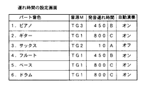
MIDIイベントに対する処理が行われる前に、各パート毎に発音遅れ時間(レーテンシー)が予め設定される。その設定例を図4に示す。図において「パート音色」の欄は、パート番号と、対応する音色名とを示す。また、「音源M」の欄は、該パートに使用されるソフトウエア音源モジュールを示す。
【0016】
ここではTG1はPCM音源、TG2は物理モデル音源、TG3はFM音源である。次に、「発音遅れ時間」の欄には、遅れ時間に応じて分類したパートのグループ(A,B,C)と、各グループにおける遅れ時間(10msec,450msec,800msec)を示す。何れのパートを何れのグループに割り当てるかについては、ユーザが任意に設定できる。但し、一般的にはマニュアル演奏に係るパートを、最も発音遅れ時間の短いグループAに割り当てることが好適である。
【0017】
上記例にあっては、パート3の「サックス」のみがグループAに分類されている。これは、パート3のMIDIイベントはMIDIインターフェース25を介してリアルタイムに発生することとし、他のパートについてはハードディスク26あるいはリムーバブルディスク27等に予め記憶された演奏情報に基づいてMIDIイベントが発生することを想定しているものである。
【0018】
図4における全てのパートは、ハードディスク26等に予め記憶された演奏情報に基づいて自動演奏を行うことが可能になっている。但し、何れか一または複数のパートは自動演奏をオフにしておき、MIDIインターフェース25を介してユーザがマニュアル演奏を行えるようにすることができる。自動演奏のオン/オフ状態の設定を図4の最右欄に示す。上述したように、パート3の「サックス」はマニュアル演奏されることを想定しているため、該パートについてのみ自動演奏がオフに設定されている。この図4に示す設定状態は、RAM23内の所定の領域に格納される。
【0019】
2.3.MIDIイベント処理
上記MIDIイベントが発生すると、図5に示すMIDIイベント処理ルーチンが起動される。図において処理がステップSP10に進むと、発生したMIDIイベントがRAM23内の所定領域に取り込まれる。次に、処理がステップSP11に進むと、該MIDIイベントはグループA,B,Cの何れに属するかが判定される。
【0020】
ここで、グループAに属するものと判定されると、処理はステップSP12に進み、該MIDIイベントが発生タイミングを示すタイミング情報とともに入力バッファ領域37内の所定領域(入力バッファ(A))に書込まれる。同様に、グループBまたはCに属するものと判定された場合は、処理はそれぞれステップSP12またはSP13に進み、対応する入力バッファ(B)または(C)に該MIDIイベントがタイミング情報とともに書込まれる。
【0021】
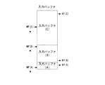
ここで、入力バッファ(A),(B)および(C)のメモリマップを図6に示す。入力バッファ(A),(B)および(C)は、それぞれ独立したリングバッファとして使用される。図において書込みポインタWP(A),WP(B)およびWP(C)は、各々入力バッファ(A),(B)および(C)内における書込みアドレスを指標しており、MIDIイベントが書込まれる毎に対応するバッファ内で循環的にインクリメントされる。
【0022】
2.4.生成トリガイベント処理
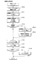
本実施形態においては、所定の波形生成周期毎に生成トリガイベント(割込み)が発生し、図7に示す生成トリガイベント処理ルーチンが起動される。図において処理がステップSP20に進むと、グループAにおける波形データの生成範囲が決定される。この生成範囲は、次の生成トリガイベントが発生するまで波形データを充分に提供できるように決定される。
【0023】
次に、処理がステップSP21に進むと、この生成範囲におけるMIDIイベントが入力バッファ(A)から取り込まれる。次に処理がステップSP22に進むと、該MIDIイベントおよびタイミング情報に基づいて、この範囲における波形データが生成され、出力バッファ領域38に書込まれる。
【0024】
ここで、出力バッファ領域38のメモリマップを図3に示す。図において書込みポインタGWP(A),GWP(B)およびGWP(C)は、各々グループA,B,Cの楽音波形生成処理で生成された波形データの書込みアドレスを指標し、書込みポインタGWP(E)はこれらグループA,B,Cの波形データにエフェクト処理を施した波形データの書込みアドレスを指標する。
【0025】
図において、領域101にはグループCで生成された波形データが、領域102にはグループB,Cで生成された波形データの混合波形データが、また、領域103にはグループA,B,Cで生成された波形データの混合波形データがそれぞれ記憶されている。また、領域103に記憶された波形データのうち書込みポインタGWP(E)と読出しポインタRPに挟まれた領域の波形データはエフェクト処理済みの波形データである。
【0026】
なお、書込みポインタGWP(A),GWP(B)およびGWP(C)は本来は各パート毎に設けられるものであるが、図3においては説明の簡素化のために、グループA,B,Cの各々について1パートづつ(合計3パート)割り当てられていることとしている。GRP(A),GRP(B)およびGRP(C)は各目標ポインタであり、読出しポインタRPとの差はグループA,B,Cにおける発音遅れ時間に応じて決定される。また、目標ポインタGRP(A),GRP(B)およびGRP(C)と、対応する書込みポインタGWP(A),GWP(B)およびGWP(C)との差は、各グループの楽音波形生成処理の遅れ具合を表す。
【0027】
書込みポインタGWP(A),GWP(B)およびGWP(C)のうち最も進んだ書込みポインタに関しては、そのポインタが示す位置に生成された波形データがそのまま書込まれ、それ以外の書込みポインタに関しては、生成された波形データを、これから書込もうとする位置に記憶されている波形データに足しこむ形で書込むようになっている。
【0028】
そして、目標ポインタGRP(A),GRP(B)およびGRP(C)と、読出しポインタRPとは、サンプリング周期毎に1アドレス(波形データの1サンプルに相当する量)づつ進行する。その処理については後述するが、図3においてはその進行方向を矢印で示しておく。
【0029】
これら書込み、読出しおよび目標ポインタは出力バッファ領域38全体の中で循環的にインクリメントされる。すなわち、各ポインタは、出力バッファ領域38の最終アドレスに達した後は出力バッファ領域38の先頭アドレスに戻ることになる。従って、先のステップSP22において生成された波形データは、図上で書込みポインタGWP(A)の先の領域(図3の書込みポインタGWP(A)から下方向の領域)に書込まれる。
【0030】
すなわち、生成された波形データは、GWP(A)の先の領域に新たに書込まれるか、既に書込まれた内容に足し込まれる。そして、波形データが書込まれた最終位置に書込みポインタGWP(A)が移動される(書込みポインタGWP(A)が下方向に移動する)。
【0031】
図7に戻り、処理がステップSP23に進むと、先にグループAについて決定された波形データの生成範囲と同一の範囲について、グループBおよびCの波形データが既に生成されているか否かが判定される。ここで「NO」と判定されると、処理はステップSP24に進み、タイミング情報に基づいて該範囲におけるグループBおよびCのMIDIイベントが取り込まれる。
【0032】
次に処理がステップSP25に進むと、取り込まれたMIDIイベントに基づいて、グループBおよびCに係る波形データが各々生成され、上記書込みポインタGWP(B)およびGWP(C)の先の領域に各々書込まれる(または足し込まれる)とともに、書込まれた最終位置に書込みポインタGWP(B)およびGWP(C)が変更される。なお、該生成範囲におけるグループBおよびCの波形データが既に生成されている場合は、上記ステップSP24,SP25はスキップされる。
【0033】
図3に見られるように、通常は書込みポインタGWP(B)およびGWP(C)は書込みポインタGWP(A)よりも相当に進んでいるため、ステップSP23の判定は殆どの場合「YES」になる。ソフトウエア音源以外の処理で負荷が大きくなった等の理由でグループBおよび/またはCの楽音波形生成処理が遅れて書込みポインタGWP(B),GWP(C)の位置が書込みポインタGWP(A)の位置と等しくなった場合にのみ、ステップSP23で「NO」と判定されることになる。
【0034】
次に、処理がステップSP26に進むと、グループA,B,Cで生成された波形データの混合波形データに対してエフェクト処理が施される。具体的には、図3に示す書込みポインタGWP(A)とGWP(E)に挟まれた領域の波形データが読み出される。
【0035】
そして、読み出された各グループの波形データに対してエフェクト処理が施され、その結果得られた波形データが同領域に再び書込まれる。次に、処理がステップSP27に進むと、書込みポインタGWP(E)の位置が書込みポインタGWP(A)と同一の位置に変更される。
【0036】
次に、処理がステップSP28に進むと、生成トリガイベント処理ルーチン(図7)に対して割当てられた時間に余裕があるか否かが判定される。時間余裕がある場合は処理はステップSP29に進み、グループBおよびCに係る波形データが該時間余裕に応じて生成される。具体的にはステップSP29においては、図9におけるサブルーチンが呼び出される。
【0037】
図9において処理がステップSP50に進むと、グループBおよびCにおける生成範囲が上記時間余裕に応じて決定される。ここでは、グループBまたはCの波形生成処理の遅れを解消するように、それぞれ、時間余裕が許す範囲内で生成範囲が決定される。すなわち、当該グループの遅れが大きい場合には、より大きな生成範囲が指定される。
【0038】
次に処理がステップSP51に進むと、タイミング情報に基づいてグループBの生成範囲におけるMIDIイベントが入力バッファ領域37の入力バッファ(B)から取り込まれる。次に、処理がステップSP52に進むと、取り込まれたMIDIイベントに基づいて、該生成範囲におけるグループBの波形データが生成される。生成された波形データは出力バッファ領域38の書込みポインタGWP(B)の先の領域に書込まれ(新規に書込まれ、または足し込まれ)、書込んだ最終位置に書込みポインタGWP(B)が更新される。
【0039】
次に処理がステップSP53に進むと、タイミング情報に基づいてグループCの生成範囲におけるMIDIイベントが入力バッファ領域37の入力バッファ(C)から取り込まれる。次に、処理がステップSP54に進むと、取り込まれたMIDIイベントに基づいて、該生成範囲におけるグループCの波形データが生成される。生成された波形データは出力バッファ領域38の書込みポインタGWP(C)の先の領域に書込まれ(新規に書込まれ、または足し込まれ)、書込んだ最終位置に書込みポインタGWP(B)が更新される。
【0040】
2.5.DMA処理
サンプリングクロック発生器33がサンプリング周期でクロックを発生すると、このクロック毎にDMA割込みが発生し、図8に示すDMA処理ルーチンが呼び出される。図において処理がステップSP40に進むと、読出しポインタRPが「1」だけインクリメントされる。但し、読出しポインタRPが既に出力バッファ領域38の終端アドレスに達していた場合は、読出しポインタRPは出力バッファ領域38の先頭アドレスに設定される。
【0041】
すなわち、出力バッファ領域38の先頭アドレスを「0」としたとき、読出しポインタRPは、「現在のRPに「1」を加えた結果を出力バッファ領域38の大きさ(SIZE)で除算した余り」に設定される。次に処理がステップSP41に進むと、更新後の読出しポインタRPによって指標されたワードが出力バッファ領域38から読み出され、第2DMAコントローラ34を介してDAコンバータ35に供給され、図示せぬサウンドシステムを介して発音される。
【0042】
3.実施形態の効果
上記生成トリガイベント処理においては生成トリガイベント処理に対する時間余裕がある場合はステップSP29において比較的長い範囲のグループBおよびCの波形データが生成される。従って、グループAに係る波形データが生成される際には、殆どの場合において同一範囲のグループBおよびCの波形データは生成済みであり、ステップSP23においては「YES」と判定される。
【0043】
換言すれば、グループBおよびCに係る波形データは時間余裕があれば事前に生成されるから、グループAの波形データの作成のために多量の処理が必要となる生成範囲が一時的に存在したとしても、同範囲におけるグループBまたはCの波形データは事前に作成されている可能性が高くなり、楽音が途切れるような不具合を未然に防止することができる。
【0044】
4.変形例
本発明は上述した実施形態に限定されるものではなく、例えば以下のように種々の変形が可能である。
(1)上記実施形態においては、楽音合成システムのプログラムは全てパーソナルコンピュータにインストールされていることを前提として説明したが、これらのプログラムをCD−ROM、フロッピーディスク等の記録媒体に格納して頒布してもよいし、或いは、無線やネットワーク等を介して各コンピュータに配信してもよい。
【0045】
(2)上記実施形態においては、最も発音遅れ時間の短いグループ(グループA)に割り当てるパートをユーザが決定した。しかし、図4に示すように、自動演奏を行うことが可能な複数のパートのうち何れかのパートがオフにされる場合は、当該パートについてマニュアル演奏が行われる可能性が高い。そこで、自動演奏をオフにしたパートを自動的にグループAに割り当てるようにしてもよい。
【0046】
【発明の効果】
以上説明したようにこの発明によれば、演奏情報が提供されてから楽音信号を出力する迄の遅延時間を、演奏情報のパートに応じて、あるいは、自動演奏であるかマニュアル演奏であるかに応じて設定するから、演奏情報の態様に応じて適切な遅延時間を設定できる。
【図面の簡単な説明】
【図1】本発明の一実施形態の楽音合成システムのブロック図である。
【図2】RAM23および波形インターフェース30の詳細ブロック図である。
【図3】出力バッファ領域38のメモリマップである。
【図4】各パートの遅延時間等の設定状態を示す図である。
【図5】MIDIイベント処理ルーチンのフローチャートである。
【図6】入力バッファ領域37のメモリマップである。
【図7】生成トリガイベント処理ルーチンのフローチャートである。
【図8】DMA処理ルーチンのフローチャートである。
【図9】生成トリガイベント処理ルーチンのサブルーチンのフローチャートである。
【符号の説明】
20……CPUバス、21……CPU、22……ROM、23……RAM、24……タイマ、25……MIDIインターフェース、26……ハードディスク、27……リムーバブルディスク、28……表示器、29……キーボード&マウス、30……波形インターフェース、31……ADコンバータ、32……第1DMAコントローラ、33……サンプリングクロック発生器、34……第2DMAコントローラ、35……DAコンバータ、36……波形テーブル領域、37……入力バッファ領域、38……出力バッファ領域。[0001]
TECHNICAL FIELD OF THE INVENTION
The present invention provides a method for generating a musical tone suitable for a so-called software sound source.andMusic generatorToRelated.
[0002]
[Prior art]
In recent years, a so-called software sound source that synthesizes a musical sound waveform using a general-purpose personal computer or the like has been put to practical use. In the case of a software sound source as well, it is possible to perform an ensemble by generating musical sound waveforms of a plurality of parts, similarly to a hardware sound source device. On the other hand, a general-purpose personal computer needs to perform various processes in addition to generating a musical tone waveform, and it is difficult to generate a musical tone waveform completely in real time. In addition, in order to effectively utilize the processing power of the CPU, it is often advantageous to generate a musical tone waveform within a certain range at once.
[0003]
Therefore, in the case of a software tone generator, it is common to first generate waveform data to be generated in the future based on performance information and store it in a buffer, and thereafter read out this buffer every sampling period to reproduce the waveform data. It is a target. Then, when the waveform data of the portion that has not been reproduced is less than the predetermined amount, the subsequent waveform data is generated based on the remaining performance information and written into the buffer. Therefore, a certain delay time is required from when the performance information is supplied to the software sound source to when the sound is actually generated. This delay time is called latency.
[0004]
The performance information supplied to the software sound source may be performance information stored in a file or the like in advance, and performance information input in real time from an external performance operator or the like. In the former case, a sufficient length of latency may be set in advance. However, in the latter case, if the latency is too long, a time lag between the operation of the performance operator by the user and the actual sound generation becomes noticeable, which hinders the performance. On the other hand, if the latency is too short, a problem often occurs in which the waveform generation processing cannot be performed in time and the sound generation is interrupted. As described above, when performance information is input in real time from a performance operator or the like, it is necessary to reduce the latency as much as possible without interfering with reproduction.
[0005]
[Problems to be solved by the invention]
By the way, when both the performance information stored in a file or the like in advance and the performance information inputted in real time from an external performance operator or the like are provided to the software sound source, that is, an ensemble of an automatic performance and a manual performance is provided. May be performed. In such a case, since the latency is set uniformly in the conventional software sound source, it is difficult to sufficiently reduce the latency.
[0006]
This is because, when the waveform generation processing of the automatic performance and the manual performance is concentrated in a short period of time and exceeds the processing capability of the CPU, a problem such as the interruption of the sound occurs as described above. SUMMARY OF THE INVENTION The present invention has been made in view of the above circumstances, and provides a tone generation method capable of setting an appropriate delay time according to the form of performance information.andMusic generatorToIt is intended to provide.
[0007]
[Means for Solving the Problems]
In order to solve the above-mentioned problem, in the configuration of
In the configuration according to
In the configuration according to the third aspect,An input step of inputting performance information of a plurality of parts, a specifying step of specifying one of the plurality of parts as a manual performance part, and a second delay time for a part of the plurality of parts specified as a manual performance part. Setting and setting a first delay time longer than the second delay time to each part other than the manual performance part; and setting the first delay time after the performance information of each part other than the manual performance part is input. A first generation step of generating a first tone signal to be output when one delay time has elapsed based on the performance information of each part; and a second generation time period after the performance information of the manual performance part is input. A second generation step of generating a second tone signal to be output when the time has elapsed based on the performance information of the manual performance part; Having an addition step of adding at each other that the output timing of each of said first tone signal second tone signal in common, and an output step of outputting a musical tone signal generated by the additionIt is characterized by the following.
In the configuration of
Further, in the configuration according to the fifth aspect, input means for inputting performance information of the first part and performance information of the second part, a first delay time, and a second delay different from the first delay time Setting means for setting a time, and generating a first tone signal to be output when the first delay time has elapsed after the performance information of the first part is inputted, based on the performance information of the first part. First generating means for generating, based on the performance information of the second part, a second tone signal to be output when the second delay time elapses after the performance information of the second part is input. 2 generating means, adding means for adding the first tone signal and the second tone signal to ones having common output timings, and output means for outputting the tone signal generated by the addition. Characterized by
Further, in the configuration according to claim 6, input means for inputting performance information of a plurality of parts, designating means for designating any of the plurality of parts as a manual performance part, Setting means for setting a second delay time to a part designated as a performance part and setting a first delay time longer than the second delay time to each part other than the manual performance part; First generating means for generating, based on the performance information of each part, a first tone signal to be output when the first delay time elapses after the performance information of each part is input; The second tone signal to be output when the second delay time elapses after the performance information of the manual performance part is input Second generating means for generating the tone signal based on the output signal, adding the first tone signal and the second tone signal to ones having common output timings, and outputting the tone signal generated by the addition. Output means.
8. The musical tone generator according to claim 7, wherein the musical tone generator outputs the musical tone signal of each of the parts based on the musical performance information of a plurality of parts. Means for making the delay time until the output of the part different depending on the part.
Further, in the musical sound generating apparatus for outputting a musical tone signal based on musical performance information, the delay time from when the musical performance information is provided to when the musical tone signal is output may be set to be the same as the musical performance. It is characterized by comprising means for setting according to whether the information is performance information relating to automatic performance or performance information relating to manual performance.
[0008]
BEST MODE FOR CARRYING OUT THE INVENTION
1. Configuration of the embodiment
A hardware configuration of a tone synthesis system according to an embodiment of the present invention will be described with reference to FIG. Note that the present embodiment is realized on a general-purpose personal computer. In the figure,
[0009]
A
[0010]
[0011]
Here, details of the
[0012]
[0013]
In the
[0014]
2. Operation of the embodiment
2.1. Process to generate MIDI event
In the tone synthesis system according to the present embodiment, a MIDI event is generated each time a MIDI signal is supplied via the
[0015]
2.2. Setting the sound delay time for each part
Before the processing for the MIDI event is performed, a sound generation delay time (latency) is set in advance for each part. FIG. 4 shows an example of the setting. In the figure, the column of “part timbre” shows a part number and a corresponding timbre name. Further, the column of “sound source M” indicates a software sound source module used for the part.
[0016]
Here, TG1 is a PCM sound source, TG2 is a physical model sound source, and TG3 is an FM sound source. Next, the column of “sound delay time” shows the group of parts (A, B, C) classified according to the delay time, and the delay time (10 msec, 450 msec, 800 msec) in each group. The user can arbitrarily set which part is to be assigned to which group. However, it is generally preferable to assign a part related to the manual performance to the group A having the shortest sound delay time.
[0017]
In the above example, only “Sax” in
[0018]
All parts in FIG. 4 can perform an automatic performance based on performance information stored in advance on the
[0019]
2.3. MIDI event processing
When the MIDI event occurs, a MIDI event processing routine shown in FIG. 5 is started. In the figure, when the process proceeds to step SP10, the generated MIDI event is taken into a predetermined area in the
[0020]
Here, if it is determined that the MIDI event belongs to the group A, the process proceeds to step SP12, and is written into a predetermined area (input buffer (A)) in the
[0021]
FIG. 6 shows a memory map of the input buffers (A), (B) and (C). The input buffers (A), (B) and (C) are used as independent ring buffers. In the figure, write pointers WP (A), WP (B) and WP (C) indicate write addresses in input buffers (A), (B) and (C), respectively, and a MIDI event is written. Each time it is cyclically incremented in the corresponding buffer.
[0022]
2.4. Generation trigger event processing
In the present embodiment, a generation trigger event (interruption) occurs at every predetermined waveform generation period, and the generation trigger event processing routine shown in FIG. 7 is started. In the figure, when the processing proceeds to step SP20, the generation range of the waveform data in the group A is determined. The generation range is determined so that sufficient waveform data can be provided until the next generation trigger event occurs.
[0023]
Next, when the process proceeds to step SP21, a MIDI event in this generation range is fetched from the input buffer (A). Next, when the process proceeds to step SP22, waveform data in this range is generated based on the MIDI event and the timing information, and written into the
[0024]
Here, a memory map of the
[0025]
In the figure, an
[0026]
Note that the write pointers GWP (A), GWP (B) and GWP (C) are originally provided for each part, but in FIG. 3, for simplicity of explanation, the groups A, B, C Are assigned one by one (a total of three parts). GRP (A), GRP (B) and GRP (C) are each target pointer, and the difference from the read pointer RP is determined according to the sound generation delay time in the groups A, B and C. The difference between the target pointers GRP (A), GRP (B) and GRP (C) and the corresponding write pointers GWP (A), GWP (B) and GWP (C) is determined by the tone waveform generation processing of each group. Represents the degree of delay.
[0027]
Among the write pointers GWP (A), GWP (B) and GWP (C), the waveform data generated at the position indicated by the pointer is written as it is, and the other write pointers are written at the position indicated by the pointer. The generated waveform data is written in such a manner as to be added to the waveform data stored at the position to be written.
[0028]
Then, the target pointers GRP (A), GRP (B) and GRP (C) and the read pointer RP advance by one address (an amount corresponding to one sample of waveform data) every sampling period. Although the processing will be described later, the traveling direction is indicated by an arrow in FIG.
[0029]
These write, read and target pointers are cyclically incremented throughout the
[0030]
That is, the generated waveform data is newly written in the area ahead of the GWP (A) or is added to the already written contents. Then, the write pointer GWP (A) is moved to the final position where the waveform data has been written (the write pointer GWP (A) moves downward).
[0031]
Returning to FIG. 7, when the process proceeds to step SP23, it is determined whether or not the waveform data of groups B and C have already been generated in the same range as the generation range of the waveform data determined for group A previously. You. If "NO" here, the process proceeds to step SP24 to fetch MIDI events of the groups B and C in the range based on the timing information.
[0032]
Next, when the process proceeds to step SP25, the waveform data relating to the groups B and C are generated based on the fetched MIDI event, and the waveform data are respectively stored in the areas ahead of the write pointers GWP (B) and GWP (C). As the data is written (or added), the write pointers GWP (B) and GWP (C) are changed to the last written position. If the waveform data of groups B and C in the generation range has already been generated, steps SP24 and SP25 are skipped.
[0033]
As can be seen from FIG. 3, normally, the write pointers GWP (B) and GWP (C) are considerably more advanced than the write pointer GWP (A), so that the determination in step SP23 is "YES" in most cases. . The processing of generating musical tone waveforms of groups B and / or C is delayed due to an increase in load due to processing other than the software sound source, and the positions of the write pointers GWP (B) and GWP (C) are changed to the write pointer GWP (A) Is determined to be "NO" in step SP23 only when the position becomes equal to the position.
[0034]
Next, when the process proceeds to step SP26, an effect process is performed on the mixed waveform data of the waveform data generated in the groups A, B, and C. Specifically, the waveform data in the area between the write pointers GWP (A) and GWP (E) shown in FIG. 3 is read.
[0035]
Then, effect processing is performed on the read-out waveform data of each group, and the resulting waveform data is written again in the same area. Next, when the process proceeds to step SP27, the position of the write pointer GWP (E) is changed to the same position as the write pointer GWP (A).
[0036]
Next, when the process proceeds to step SP28, it is determined whether or not there is enough time allocated to the generation trigger event processing routine (FIG. 7). If there is enough time, the process proceeds to step SP29, and waveform data relating to groups B and C is generated according to the time allowance. Specifically, in step SP29, the subroutine in FIG. 9 is called.
[0037]
In FIG. 9, when the process proceeds to step SP50, the generation ranges of the groups B and C are determined according to the time margin. Here, the generation range is determined within the range allowed by the time margin so as to eliminate the delay of the waveform generation processing of the group B or C. That is, when the delay of the group is large, a larger generation range is specified.
[0038]
Next, when the process proceeds to step SP51, a MIDI event in the generation range of the group B is fetched from the input buffer (B) of the
[0039]
Next, when the process proceeds to step SP53, the MIDI event in the generation range of the group C is fetched from the input buffer (C) of the
[0040]
2.5. DMA processing
When the
[0041]
That is, when the head address of the
[0042]
3. Effects of the embodiment
In the above generation trigger event processing, if there is enough time for the generation trigger event processing, the waveform data of the groups B and C in a relatively long range is generated in step SP29. Therefore, when the waveform data for the group A is generated, in most cases, the waveform data for the groups B and C in the same range has already been generated, and it is determined “YES” in step SP23.
[0043]
In other words, the waveform data relating to the groups B and C are generated in advance if there is enough time, so that a generation range in which a large amount of processing is required for generating the waveform data of the group A temporarily existed. However, it is highly likely that the waveform data of the group B or C in the same range has been created in advance, and it is possible to prevent a problem that the musical sound is interrupted beforehand.
[0044]
4. Modified example
The present invention is not limited to the embodiments described above, and various modifications are possible, for example, as follows.
(1) In the above embodiment, the description has been made on the assumption that all the programs of the tone synthesis system are installed in the personal computer. However, these programs are stored in a recording medium such as a CD-ROM or a floppy disk and distributed. Or may be distributed to each computer via wireless or network.
[0045]
(2) In the above embodiment, the user determines the part to be assigned to the group (group A) with the shortest sound delay time. However, as shown in FIG. 4, when any one of a plurality of parts capable of performing an automatic performance is turned off, there is a high possibility that a manual performance will be performed for that part. Therefore, a part for which automatic performance is turned off may be automatically assigned to group A.
[0046]
【The invention's effect】
As described above, according to the present invention, the delay time from when the performance information is provided to when the musical sound signal is output is determined according to the part of the performance information, whether the performance is automatic or manual. Therefore, an appropriate delay time can be set according to the form of the performance information.
[Brief description of the drawings]
FIG. 1 is a block diagram of a musical sound synthesis system according to an embodiment of the present invention.
FIG. 2 is a detailed block diagram of a
FIG. 3 is a memory map of an
FIG. 4 is a diagram showing a setting state of a delay time and the like of each part.
FIG. 5 is a flowchart of a MIDI event processing routine.
FIG. 6 is a memory map of an
FIG. 7 is a flowchart of a generation trigger event processing routine.
FIG. 8 is a flowchart of a DMA processing routine.
FIG. 9 is a flowchart of a subroutine of a generation trigger event processing routine.
[Explanation of symbols]
20 CPU bus, 21 CPU, 22 ROM, 23 RAM, 24 timer, 25 MIDI interface, 26 hard disk, 27 removable disk, 28 display, 29 ... keyboard & mouse, 30 ... waveform interface, 31 ... AD converter, 32 ... first DMA controller, 33 ... sampling clock generator, 34 ... second DMA controller, 35 ... DA converter, 36 ... waveform Table area, 37: input buffer area, 38: output buffer area
Claims (8)
サンプリング周期ごとに出力バッファの読出しポインタを更新する一方、当該出力バッファに書き込まれた楽音信号のうち前記読出しポインタが示すサンプルを前記出力バッファから読み出して出力する出力過程と、
前記読出しポインタと第1書込みポインタとの差分に応じた範囲の第1楽音信号を前記第1パートの演奏情報に基づいて生成する一方、この生成した第1楽音信号を前記出力バッファのうち前記第1の書込みポインタが示す領域に新規に書き込むとともに当該第1の書込みポインタを更新する第1生成過程と、
前記読出しポインタと第2書込みポインタとの差分に応じた範囲の第2楽音信号を前記第2パートの演奏情報に基づいて生成する一方、この生成した第2楽音信号と前記出力バッファのうち前記第2の書込みポインタが示す領域に既に書き込まれている楽音信号とを加算して得られる楽音信号を当該第2の書込ポインタが示す領域に書き込むとともに当該第2の書込みポインタを更新する第2生成過程と
を有し、前記入力過程において前記第1パートの演奏情報が入力されてから当該演奏情報に対応した前記第1楽音信号のサンプルが前記出力過程において出力されるまでの遅延時間が、前記入力過程において前記第2パートの演奏情報が入力されてから当該演奏情報に対応した前記第2楽音信号のサンプルが前記出力過程において出力されるまでの遅延時間よりも長い
ことを特徴とする楽音生成方法。 Inputting the performance information of the first part and the performance information of the second part;
An output step of reading a sample indicated by the read pointer from the output buffer and outputting the sample indicated by the read pointer among the tone signals written to the output buffer while updating the read pointer of the output buffer every sampling period;
A first tone signal in a range corresponding to a difference between the read pointer and the first write pointer is generated based on the performance information of the first part, and the generated first tone signal is output to the second buffer in the output buffer. A first generation step of newly writing to the area indicated by the first write pointer and updating the first write pointer;
A second tone signal in a range corresponding to a difference between the read pointer and the second write pointer is generated based on the performance information of the second part, and the generated second tone signal and the second buffer of the output buffer are generated. A second generation for writing a tone signal obtained by adding the tone signal already written in the area indicated by the second write pointer to the area indicated by the second write pointer and updating the second write pointer Process and
A delay time from when the performance information of the first part is input in the input process to when a sample of the first tone signal corresponding to the performance information is output in the output process, Wherein the delay time from when the performance information of the second part is input to when the sample of the second tone signal corresponding to the performance information is output in the output process is longer. Musical tone generation method.
第1遅延時間と、当該第1遅延時間とは異なる第2遅延時間とを設定する設定過程と、
前記第1パートの演奏情報が入力されてから前記第1遅延時間が経過したときに出力すべき第1楽音信号を前記第1パートの演奏情報に基づいて生成する第1生成過程と、
前記第2パートの演奏情報が入力されてから前記第2遅延時間が経過したときに出力すべき第2楽音信号を前記第2パートの演奏情報に基づいて生成する第2生成過程と、
前記第1楽音信号と前記第2楽音信号とを各々の出力タイミングが共通するもの同士で加算する加算過程と、
この加算により生成された楽音信号を出力する出力過程と
を有することを特徴とする楽音生成方法。 Inputting the performance information of the first part and the performance information of the second part;
Setting a first delay time and a second delay time different from the first delay time;
A first generation step of generating, based on the performance information of the first part, a first tone signal to be output when the first delay time has elapsed since the input of the performance information of the first part;
A second generation step of generating, based on the performance information of the second part, a second tone signal to be output when the second delay time elapses after the performance information of the second part is input;
An adding step of adding the first musical tone signal and the second musical tone signal by those having common output timings;
An output process of outputting the tone signal generated by this addition;
Tone generating method characterized by having a.
前記複数パートのうちの何れかをマニュアル演奏パートとして指定する指定過程と、A designation step of designating any of the plurality of parts as a manual performance part;
前記複数パートのうちマニュアル演奏パートとして指定されたパートに第2遅延時間を設定するとともに、前記マニュアル演奏パート以外の各パートに前記第2遅延時間よりも長い第1遅延時間を設定する設定過程と、Setting a second delay time to a part designated as a manual performance part among the plurality of parts, and setting a first delay time longer than the second delay time to each part other than the manual performance part; ,
前記マニュアル演奏パート以外の各パートの演奏情報が入力されてから前記第1遅延時間が経過したときに出力すべき第1楽音信号を当該各パートの演奏情報に基づいて生成する第1生成過程と、A first generation step of generating a first tone signal to be output when the first delay time elapses after the performance information of each part other than the manual performance part is input, based on the performance information of each part; ,
前記マニュアル演奏パートの演奏情報が入力されてから前記第2遅延時間が経過したときに出力すべき第2楽音信号を当該マニュアル演奏パートの演奏情報に基づいて生成する第2生成過程と、A second generation step of generating a second tone signal to be output when the second delay time elapses after the performance information of the manual performance part is input, based on the performance information of the manual performance part;
前記第1楽音信号と前記第2楽音信号とを各々の出力タイミングが共通するもの同士で加算する加算過程と、An adding step of adding the first musical tone signal and the second musical tone signal by those having common output timings;
この加算により生成された楽音信号を出力する出力過程とAn output process of outputting the tone signal generated by this addition;
を有することを特徴とする楽音生成方法。A tone generation method comprising:
サンプリング周期ごとに出力バッファの読出しポインタを更新する一方、当該出力バッWhile updating the read pointer of the output buffer every sampling period, ファに書き込まれた楽音信号のうち前記読出しポインタが示すサンプルを前記出力バッファから読み出して出力する出力手段と、Output means for reading out from the output buffer a sample indicated by the read pointer out of the tone signals written to the
前記読出しポインタと第1書込みポインタとの差分に応じた範囲の第1楽音信号を前記第1パートの演奏情報に基づいて生成する一方、この生成した第1楽音信号を前記出力バッファのうち前記第1の書込みポインタが示す領域に新規に書き込むとともに当該第1の書込みポインタを更新する第1生成手段と、A first tone signal in a range corresponding to a difference between the read pointer and the first write pointer is generated based on the performance information of the first part, and the generated first tone signal is output to the second buffer in the output buffer. First generating means for newly writing to the area indicated by the first write pointer and updating the first write pointer;
前記読出しポインタと第2書込みポインタとの差分に応じた範囲の第2楽音信号を前記第2パートの演奏情報に基づいて生成する一方、この生成した第2楽音信号と前記出力バッファのうち前記第2の書込みポインタが示す領域に既に書き込まれている楽音信号とを加算して得られる楽音信号を当該第2の書込ポインタが示す領域に書き込むとともに当該第2の書込みポインタを更新する第2生成手段とA second tone signal in a range corresponding to the difference between the read pointer and the second write pointer is generated based on the performance information of the second part, and the generated second tone signal and the second buffer of the output buffer are generated. A second generation for writing a tone signal obtained by adding the tone signal already written in the area indicated by the second write pointer to the area indicated by the second write pointer and updating the second write pointer Means
を具備し、前記入力手段により前記第1パートの演奏情報が入力されてから当該演奏情報に対応した前記第1楽音信号のサンプルが前記出力手段によって出力されるまでの第1遅延時間が、前記入力手段により前記第2パートの演奏情報が入力されてから当該演奏情報に対応した前記第2楽音信号のサンプルが前記出力手段によって出力されるまでの第2遅延時間よりも長いWherein the first delay time from when the performance information of the first part is input by the input means to when the sample of the first tone signal corresponding to the performance information is output by the output means, It is longer than a second delay time from when the performance information of the second part is input by the input means to when the sample of the second tone signal corresponding to the performance information is output by the output means.
ことを特徴とする楽音生成装置。A tone generation device characterized by the above-mentioned.
第1遅延時間と、当該第1遅延時間とは異なる第2遅延時間とを設定する設定手段と、Setting means for setting a first delay time and a second delay time different from the first delay time;
前記第1パートの演奏情報が入力されてから前記第1遅延時間が経過したときに出力すべき第1楽音信号を前記第1パートの演奏情報に基づいて生成する第1生成手段と、First generating means for generating, based on the performance information of the first part, a first tone signal to be output when the first delay time has elapsed after the performance information of the first part is input;
前記第2パートの演奏情報が入力されてから前記第2遅延時間が経過したときに出力すべき第2楽音信号を前記第2パートの演奏情報に基づいて生成する第2生成手段と、Second generating means for generating, based on the performance information of the second part, a second tone signal to be output when the second delay time has elapsed since the performance information of the second part was input;
前記第1楽音信号と前記第2楽音信号とを各々の出力タイミングが共通するもの同士で加算する加算手段と、Adding means for adding the first tone signal and the second tone signal to ones having common output timings;
この加算により生成された楽音信号を出力する出力手段とOutput means for outputting a tone signal generated by the addition;
を具備することを特徴とする楽音生成装置。A musical sound generation device comprising:
前記複数パートのうちの何れかをマニュアル演奏パートとして指定する指定手段と、Designating means for designating any of the plurality of parts as a manual performance part;
前記複数パートのうちマニュアル演奏パートとして指定されたパートに第2遅延時間を設定するとともに、前記マニュアル演奏パート以外の各パートに前記第2遅延時間よりも長い第1遅延時間を設定する設定手段と、Setting means for setting a second delay time for a part designated as a manual performance part among the plurality of parts, and setting a first delay time longer than the second delay time for each part other than the manual performance part; ,
前記マニュアル演奏パート以外の各パートの演奏情報が入力されてから前記第1遅延時間が経過したときに出力すべき第1楽音信号を当該各パートの演奏情報に基づいて生成する第1生成手段と、First generating means for generating a first tone signal to be output when the first delay time elapses after the performance information of each part other than the manual performance part is input, based on the performance information of each part; ,
前記マニュアル演奏パートの演奏情報が入力されてから前記第2遅延時間が経過したときに出力すべき第2楽音信号を当該マニュアル演奏パートの演奏情報に基づいて生成する第2生成手段と、Second generating means for generating a second tone signal to be output when the second delay time has elapsed after the performance information of the manual performance part is input, based on the performance information of the manual performance part;
前記第1楽音信号と前記第2楽音信号とを各々の出力タイミングが共通するもの同士で加算する加算手段と、Adding means for adding the first tone signal and the second tone signal to ones having common output timings;
この加算により生成された楽音信号を出力する出力手段とOutput means for outputting a tone signal generated by the addition;
を具備することを特徴とする楽音生成装置。A musical sound generation device comprising:
前記各パートの演奏情報が提供されてから前記各パートの楽音信号を出力する迄の遅延時間を、前記パートに応じて相違させる手段Means for differing the delay time from when the performance information of each part is provided to when the tone signal of each part is output, according to the part
を具備することを特徴とする楽音生成装置。A musical sound generation device comprising:
前記演奏情報が提供されてから前記楽音信号を出力する迄の遅延時間を、前記演奏情報 が自動演奏に係る演奏情報であるかマニュアル演奏に係る演奏情報であるかに応じて設定する手段
を具備することを特徴とする楽音生成装置。 In a tone generation device that outputs a tone signal based on performance information,
Means for setting a delay time from when the performance information is provided to when the tone signal is output , according to whether the performance information is performance information relating to automatic performance or manual performance.
A musical sound generation device comprising:
Priority Applications (1)
| Application Number | Priority Date | Filing Date | Title |
|---|---|---|---|
| JP08048599A JP3551818B2 (en) | 1999-03-24 | 1999-03-24 | Music sound generation method and music sound generation device |
Applications Claiming Priority (1)
| Application Number | Priority Date | Filing Date | Title |
|---|---|---|---|
| JP08048599A JP3551818B2 (en) | 1999-03-24 | 1999-03-24 | Music sound generation method and music sound generation device |
Publications (2)
| Publication Number | Publication Date |
|---|---|
| JP2000276149A JP2000276149A (en) | 2000-10-06 |
| JP3551818B2 true JP3551818B2 (en) | 2004-08-11 |
Family
ID=13719601
Family Applications (1)
| Application Number | Title | Priority Date | Filing Date |
|---|---|---|---|
| JP08048599A Expired - Fee Related JP3551818B2 (en) | 1999-03-24 | 1999-03-24 | Music sound generation method and music sound generation device |
Country Status (1)
| Country | Link |
|---|---|
| JP (1) | JP3551818B2 (en) |
Families Citing this family (3)
| Publication number | Priority date | Publication date | Assignee | Title |
|---|---|---|---|---|
| DE112008001574T5 (en) * | 2007-06-05 | 2010-04-29 | Advantest Corp. | Waveform generator, waveform generation method and program |
| JP7332002B2 (en) | 2018-03-22 | 2023-08-23 | カシオ計算機株式会社 | Electronic musical instrument, method and program |
| JP7124371B2 (en) | 2018-03-22 | 2022-08-24 | カシオ計算機株式会社 | Electronic musical instrument, method and program |
-
1999
- 1999-03-24 JP JP08048599A patent/JP3551818B2/en not_active Expired - Fee Related
Also Published As
| Publication number | Publication date |
|---|---|
| JP2000276149A (en) | 2000-10-06 |
Similar Documents
| Publication | Publication Date | Title |
|---|---|---|
| EP3462443B1 (en) | Singing voice edit assistant method and singing voice edit assistant device | |
| JP4240575B2 (en) | Musical sound synthesis method, recording medium, and musical sound synthesizer | |
| JP6011219B2 (en) | Audio file generation program and audio file generation apparatus | |
| JP2019066648A (en) | Method for assisting in editing singing voice and device for assisting in editing singing voice | |
| TW300298B (en) | ||
| JP2976429B2 (en) | Address control circuit | |
| JP3551818B2 (en) | Music sound generation method and music sound generation device | |
| JP3840851B2 (en) | Recording medium and tone signal generation method | |
| JP4036233B2 (en) | Musical sound generating device, musical sound generating method, and storage medium storing a program related to the method | |
| JP3637577B2 (en) | Music generation method | |
| JP3978928B2 (en) | Music generator | |
| JP5534389B2 (en) | Music generator | |
| JP3799711B2 (en) | Musical sound generation method and musical sound generator | |
| JP3781171B2 (en) | Music generation method | |
| JP3518357B2 (en) | Music generating method, musical sound generating apparatus and computer readable recording medium storing musical sound generating processing program | |
| JP3460524B2 (en) | Music data processing method, processed music data reproduction method, and storage medium | |
| JP4685226B2 (en) | Automatic performance device for waveform playback | |
| JP4645597B2 (en) | Musical sound synthesis method, recording medium, and musical sound synthesizer | |
| JP3223757B2 (en) | Musical sound wave generation method | |
| JP3407625B2 (en) | Automatic performance apparatus, automatic performance method, and medium recording program | |
| JP3938022B2 (en) | Tone setting device and program | |
| JP2765469B2 (en) | Music signal playback device | |
| JP2000122668A (en) | Digtal sound data processor, and computor system | |
| JP3659002B2 (en) | Musical sound data processing apparatus and computer system | |
| JP4862879B2 (en) | Musical sound synthesis method, recording medium, and musical sound synthesizer |
Legal Events
| Date | Code | Title | Description |
|---|---|---|---|
| A131 | Notification of reasons for refusal |
Free format text: JAPANESE INTERMEDIATE CODE: A131 Effective date: 20040106 |
|
| A521 | Written amendment |
Free format text: JAPANESE INTERMEDIATE CODE: A523 Effective date: 20040305 |
|
| TRDD | Decision of grant or rejection written | ||
| A01 | Written decision to grant a patent or to grant a registration (utility model) |
Free format text: JAPANESE INTERMEDIATE CODE: A01 Effective date: 20040406 |
|
| A61 | First payment of annual fees (during grant procedure) |
Free format text: JAPANESE INTERMEDIATE CODE: A61 Effective date: 20040419 |
|
| R150 | Certificate of patent (=grant) or registration of utility model |
Free format text: JAPANESE INTERMEDIATE CODE: R150 |
|
| S531 | Written request for registration of change of domicile |
Free format text: JAPANESE INTERMEDIATE CODE: R313532 |
|
| R350 | Written notification of registration of transfer |
Free format text: JAPANESE INTERMEDIATE CODE: R350 |
|
| FPAY | Renewal fee payment (prs date is renewal date of database) |
Free format text: PAYMENT UNTIL: 20090514 Year of fee payment: 5 |
|
| FPAY | Renewal fee payment (prs date is renewal date of database) |
Free format text: PAYMENT UNTIL: 20100514 Year of fee payment: 6 |
|
| FPAY | Renewal fee payment (prs date is renewal date of database) |
Free format text: PAYMENT UNTIL: 20110514 Year of fee payment: 7 |
|
| FPAY | Renewal fee payment (prs date is renewal date of database) |
Free format text: PAYMENT UNTIL: 20130514 Year of fee payment: 9 |
|
| FPAY | Renewal fee payment (prs date is renewal date of database) |
Free format text: PAYMENT UNTIL: 20140514 Year of fee payment: 10 |
|
| LAPS | Cancellation because of no payment of annual fees |