JP3551482B2 - Disc player device - Google Patents
Disc player device Download PDFInfo
- Publication number
- JP3551482B2 JP3551482B2 JP20211294A JP20211294A JP3551482B2 JP 3551482 B2 JP3551482 B2 JP 3551482B2 JP 20211294 A JP20211294 A JP 20211294A JP 20211294 A JP20211294 A JP 20211294A JP 3551482 B2 JP3551482 B2 JP 3551482B2
- Authority
- JP
- Japan
- Prior art keywords
- tray
- disk
- pickup device
- shaft
- outer housing
- Prior art date
- Legal status (The legal status is an assumption and is not a legal conclusion. Google has not performed a legal analysis and makes no representation as to the accuracy of the status listed.)
- Expired - Fee Related
Links
Images


Classifications
-
- G—PHYSICS
- G11—INFORMATION STORAGE
- G11B—INFORMATION STORAGE BASED ON RELATIVE MOVEMENT BETWEEN RECORD CARRIER AND TRANSDUCER
- G11B17/00—Guiding record carriers not specifically of filamentary or web form, or of supports therefor
- G11B17/02—Details
- G11B17/04—Feeding or guiding single record carrier to or from transducer unit
- G11B17/05—Feeding or guiding single record carrier to or from transducer unit specially adapted for discs not contained within cartridges
- G11B17/053—Indirect insertion, i.e. with external loading means
- G11B17/056—Indirect insertion, i.e. with external loading means with sliding loading means
-
- G—PHYSICS
- G11—INFORMATION STORAGE
- G11B—INFORMATION STORAGE BASED ON RELATIVE MOVEMENT BETWEEN RECORD CARRIER AND TRANSDUCER
- G11B19/00—Driving, starting, stopping record carriers not specifically of filamentary or web form, or of supports therefor; Control thereof; Control of operating function ; Driving both disc and head
- G11B19/02—Control of operating function, e.g. switching from recording to reproducing
-
- G—PHYSICS
- G11—INFORMATION STORAGE
- G11B—INFORMATION STORAGE BASED ON RELATIVE MOVEMENT BETWEEN RECORD CARRIER AND TRANSDUCER
- G11B17/00—Guiding record carriers not specifically of filamentary or web form, or of supports therefor
- G11B17/22—Guiding record carriers not specifically of filamentary or web form, or of supports therefor from random access magazine of disc records
- G11B17/225—Guiding record carriers not specifically of filamentary or web form, or of supports therefor from random access magazine of disc records wherein the disks are transferred from a fixed magazine to a fixed playing unit using a moving carriage
Description
【0001】
【産業上の利用分野】
本発明は、光ディスクに記録された情報信号を読み出して再生するディスクプレーヤ装置に関する。
【0002】
【従来の技術】
従来、光ディスクに記録された情報信号を光学ピックアップ装置により読み出し、この情報信号を音響信号に復調して再生するディスクプレーヤ装置が提案されている。
【0003】
このようなディスクプレーヤ装置は、外筐体内に光ディスクを搬入するローディング機構及び搬入された光ディスクをディスクテーブル上に装着させるチャッキング機構を有して構成されている。
【0004】
上記ローディング機構は、上記外筐体の内外に亘って移動操作されるディスクトレイを有している。このディスクトレイは、上記外筐体の外方側に移動された状態で、光ディスクを位置決めして載置される。そして、このディスクトレイは、光ディスクを載置させたまま、上記外筐体内に移動操作されることにより、該光ディスクを該外筐体内に搬入する。
【0005】
上記チャッキング機構は、ディスクドライブ部を構成する上記ディスクテーブルと、このディスクテーブルに対向して配設され回転可能となされたチャッキングプレートとを有している。
【0006】
上記ディスクドライブ部は、上記光学ピックアップ装置と、駆動軸に上記ディスクテーブルが取り付けられたスピンドルモータとを有して構成されている。上記光学ピックアップ装置は、上記ディスクドライブ部において、上記ディスクテーブルに対する接離方向に移動操作可能となされている。
【0007】
上記ディスクドライブ部は、上記ディスクテーブルを上記チャッキングプレートに対して接離させる方向に移動操作可能となされている。そして、上記ディスクトレイにより搬入された光ディスクは、上記ディスクテーブルと上記チャッキングプレートとの間に位置されている。上記光ディスクが搬入された後、上記ディスクテーブルが上記チャッキングプレート側に移動されると、これらディスクテーブル及びチャッキングプレートは、共働して上記光ディスクを挟持して保持する。
【0008】
そして、上記スピンドルモータが回転駆動されると、上記ディスクテーブルは、上記光ディスク及び上記チャッキングプレートを伴って、回転操作される。回転操作されている光ディスクは、上記光ピックアップ装置により、情報信号の読み出しを行われる。
【0009】
【発明が解決しようとする課題】
ところで、上述のようなディスクプレーヤ装置においては、上記ローディング機構による光ディスクの搬入が終了した後、この光ディスクに対するチャッキングが行われる。そのため、このディスクプレーヤ装置においては、上記ディスクトレイに上記光ディスクを載置してからこの光ディスクの再生が実行されるまでの時間を短縮することが困難である。
【0010】
ここで、上記ディスクドライブ部を上記ディスクトレイ上に装着し、このディスクドライブ部を上記外筐体の外方側まで移動操作する構成が考えられる。すなわち、上記ディスクドライブ部を上記外筐体の外方側に移動させた状態で、このディスクドライブ部に上記光ディスクを装着させれば、このディスクドライブ部を上記外筐体内に搬入したときに、即座に再生動作を実行することができる。
【0011】
しかしながら、上記ディスクトレイにより上記ディスクドライブ部を移動操作することとすると、このディスクドライブ部を上記外筐体の外方側に充分に移動させないと、このディスクドライブ部に対する上記光ディスクの着脱が困難となる。すなわち、上記ディスクドライブ部は、このディスクドライブ部に装着された光ディスクの全面が上記外筐体の外方側に位置される程度に上記外筐体の外方側に移動される必要がある。
【0012】
そして、上記ディスクドライブ部を充分な距離に亘って移動操作可能に支持するためには、このディスクドライブ部の重量を充分に支持できるだけの堅牢な構成が必要となる。そのため、ディスクプレーヤ装置全体の装置構成の大型化、大重量化が招来されることとなる。
【0013】
そこで、本発明は、上述の実情に鑑みて提案されるものであって、装置構成の大型化、大重量化を抑制しつつ、ディスクドライブ部が外筐体の外方側に充分に移動操作され、このディスクドライブ部に対する迅速な記録ディスクの着脱が行えるようになされたディスクプレーヤ装置を提供することを目的とする。
【0014】
【課題を解決するための手段】
上述の課題を解決し上記目的を達成するため、本発明に係るディスクプレーヤ装置は、外筐体内に収納される位置及び該外筐体より外方側に突出される位置に亘って移動操作可能に支持されたトレイ部と、上記トレイ部上に固定して配設されたピックアップ装置と、上記トレイ部を移動操作する第1の駆動手段と、上記トレイ部上において上記ピックアップ装置が配設された位置よりも外方側に設けられ、該ピックアップ装置に対する接離方向に移動操作可能に支持され、記録ディスクが載置され、上記記録ディスクと共に回転操作されるディスクテーブルと、上記第1の駆動手段が上記トレイ部を上記外筐体より突出される位置に移動操作するときには、上記ディスクテーブルを該トレイ部に対する移動操作が可能な範囲内における該外筐体より最も離間する位置に移動操作させる第2の駆動手段とを備える。
【0015】
また、本発明に係るディスクプレーヤ装置は、外筐体内に収納される位置及び該外筐体より外方側に突出される位置に亘って移動操作可能に支持されたトレイ部と、上記トレイ部上に固定して配設されたピックアップ装置と、上記トレイ部を移動操作する第1の駆動手段と、上記トレイ部上において上記ピックアップ装置に対する接離方向に移動操作可能に支持され、記録ディスクが載置され、上記記録ディスクと共に回転操作されるディスクテーブルと、上記第1の駆動手段により上記トレイ部を上記外筐体内に収納される位置に移動操作するときには、上記ディスクテーブルを該ディスクテーブルに載置される記録ディスクの内周側に上記ピックアップ装置が対向する位置まで移動操作させる第2の駆動手段とを備える。
【0016】
そして、本発明は、上述の各ディスクプレーヤ装置において、上記トレイ部は、このトレイ部に取り付けられたシャフトが外筐体内に配設されたスラスト軸受けにより移動可能に支持されることによって略々このトレイ部の長さに相当する距離に亘って移動操作可能となされており、上記シャフトは、上記トレイ部の長さの略々2倍の長さを有し一端部をこのトレイ部の上記外筐体の外方側に向いた前端部の近傍に位置させ他端側をこのトレイ部の後方側に突出させて該トレイ部に取り付けられ、上記スラスト軸受けは、上記トレイ部が上記外筐体内に収納されているときにおけるこのトレイ部の前端部近傍の位置及びこのトレイ部の後端部近傍の位置において上記シャフトを支持することとしたものである。
【0017】
さらに、本発明は、上述の各ディスクプレーヤ装置において、上記ディスクテーブルは、スピンドル軸を有しピックアップ装置に対する接離方向に移動操作可能にトレイ部上に配設された支持ブロックに該スピンドル軸を回転可能に支持されて配設されており、上記支持ブロックは、導電性材料により一体的に形成されていることとしたものである。
【0018】
【作用】
本発明に係るディスクプレーヤ装置においては、トレイ部上においてディスクテーブルを移動操作する第2の駆動手段は、該トレイ部が第1の駆動手段によって外筐体より突出する位置に移動操作されるときには、該ディスクテーブルを該トレイ部に対する移動操作が可能な範囲内における該外筐体より最も離間する位置に移動操作するので、該テーブル部の該外筐体よりの突出距離を短くしつつ、該ディスクテーブルに対する記録ディスクの着脱が容易化される。
【0019】
また、本発明に係るディスクプレーヤ装置においては、トレイ部上においてディスクテーブルを移動操作する第2の駆動手段は、該トレイ部が第1の駆動手段によって外筐体内に収納される位置に移動操作されるときには、該ディスクテーブルを該トレイ部に対する移動操作が可能な範囲内におけるピックアップ装置に最も接近する位置に移動操作するので、上記トレイ部上に上記記録ディスクを装着してからこの記録ディスクに対する再生動作が実行されるまでの時間が短縮される。
【0020】
そして、上述の各ディスクプレーヤ装置において、上記トレイ部は、このトレイ部に取り付けられたシャフトが外筐体内に配設されたスラスト軸受けにより移動可能に支持されることによって略々このトレイ部の長さに相当する距離に亘って移動操作可能となされていることとし、該シャフトは、上記トレイ部の長さの略々2倍の長さを有し一端部をこのトレイ部の上記外筐体の外方側に向いた前端部の近傍に位置させ他端側をこのトレイ部の後方側に突出させて該トレイ部に取り付けられていることとし、上記スラスト軸受けは、上記トレイ部が上記外筐体内に収納されているときにおけるこのトレイ部の前端部近傍の位置及びこのトレイ部の後端部近傍の位置において上記シャフトを支持することとした場合には、上記トレイ部は、上記外筐体の外方側に移動操作された状態においても、堅牢に支持される。
【0021】
さらに、上述の各ディスクプレーヤ装置において、上記ディスクテーブルは、スピンドル軸を有しピックアップ装置に対する接離方向に移動操作可能にトレイ部上に配設された支持ブロックに該スピンドル軸を回転可能に支持されて配設されていることとし、上記支持ブロックは、導電性材料により一体的に形成されていることとした場合には、上記ディスクテーブルは、上記支持ブロックを介して外筐体に対して電気的に導通されるため、静電気を蓄積してしまうことがない。
【0022】
【実施例】
以下、本発明の具体的な実施例を図面を参照しながら説明する。
【0023】
この例は、本発明に係るディスクプレーヤ装置を、図1に示すように、直径が12cm、または、8cmのディスク基板を有して構成された記録ディスクである光ディスク201の再生を行う装置として構成した例である。この光ディスク201のディスク基板は、ポリカーボネイトの如き透明な合成樹脂材料により形成され、中央部分にチャッキング孔202を有している。このディスク基板の主面部には、射出成型により、情報信号に対応した微細な凹凸(ピット)が形成されるとともに、いわゆるスパッタリング工程により、アルミニウムの如き金属材料よりなる反射層が被着形成されている。
【0024】
この光ディスク201は、後述する光学ピックアップ装置により、集光されたレーザ光束を照射されるとともに、このレーザ光束の反射光束の強度変化を検出されることによって、情報信号の読み出しをなされる。
【0025】
[1]シャーシフレームの構成
このディスクプレーヤ装置は、図1に示すように、シャーシフレーム1を有して構成される。このシャーシフレーム1は、金属板材料が屈曲形成されることにより、底板部13と、この底板部13の両側縁部より上方側に垂設された左右一対の側板部15,14とを有して構成されている。
【0026】
上記シャーシフレーム1は、図2に示すように、このディスクプレーヤ装置の外筐体の底板72上に固定して配設される。
【0027】
上記シャーシフレーム1には、上記各側板部15,14の上端部間に亘って、天板部5が取り付けられている。この天板部5は、略々平板状に形成され、両側側部分に形成された複数の螺子挿通孔21に対応して挿通された複数の螺子20が上記各側板部15,14の上端部に形成された螺子孔16,17,18,19に螺入されることにより、上記シャーシフレーム1に取り付けられる。
【0028】
上記天板部5の下面部には、回路基板6が取り付けられている。この回路基板6は、複数の螺子挿通孔23を有し、これら螺子挿通孔23に対応して下方側より挿通された複数の螺子22が上記天板部5に形成された螺子孔に螺入されることにより、該天板部5に取り付けられている。
【0029】
[2]トレイ部の構成
上記シャーシフレーム1の底板部13上、すなわち、上記各側板部15,14間であって上記回路基板6の下方側には、ローディング機構を構成するトレイ部7が配設されている。このトレイ部7上には、後述するディスクドライブ部10が配設されている。また、このトレイ部7の上面部には、上記ディスクドライブ部10を覆って、トレイカバー11が取り付けられている。さらに、これらトレイ部7とトレイカバー11との前縁部には、図2に示すように、表示手段となる表示パネル部70が取り付けられている。
【0030】
上記トレイカバー11は、前方側に設けらた左右一対の係合孔66,66に上記トレイ部7の上面部の前方側に設けられた左右一対の係合爪57,57を係合され、後方側部分を左右一対の止め螺子69,69により該トレイ部7に固定されることにより、該トレイ部7に取り付けられている。
【0031】
上記トレイ部7は、図2に示すように、上記表示パネル部70を上記外筐体の全面パネル部71に沿わせて該外筐体内に収納されるローディング位置と、図3に示すように、該外筐体より外方側に突出されたイジェクト位置とに亘って、移動操作可能に支持されている。
【0032】
すなわち、上記トレイ部7は、このトレイ部7に前後方向に亘って取り付けられた第1及び第2のシャフト8,9が上記シャーシフレーム1の底板部13上に配設された第1及び第2のスラスト軸受け3,4に移動可能に支持されることによって、略々このトレイ部7の前後方向の長さに相当する距離に亘って、前後方向に移動操作可能となされている。
【0033】
上記第1のシャフト8は、上記トレイ部7の前後方向の長さの略々2倍の長さを有している。この第1のシャフト8は、一端部、すなわち、前端部をこのトレイ部7の前縁部の近傍に位置させ、他端側、すなわち、後端側をこのトレイ部7の後方側に突出させて、該トレイ部7の一側縁に沿ってこのトレイ部7に取り付けられている。
【0034】
この第1のシャフト8の前端部には、前端部螺子穴45が設けられている。この前端部螺子穴45には、上記トレイ部7の前端面部に形成された透孔53を挿通された止め螺子47が螺入される。また、この第1のシャフト8の略々中央部には、側部螺子穴46が設けられている。この側部螺子穴46には、上記トレイ部7の後縁側に形成された透孔を挿通された止め螺子48が螺入される。
【0035】
上記第2のシャフト9は、上記トレイ部7の前後方向の長さに略々等しい長さを有している。この第2のシャフト9は、前端部をこのトレイ部7の前縁部の近傍に位置させ、後端側をこのトレイ部7の後縁部の近傍に位置させて、該トレイ部7の他側縁に沿ってこのトレイ部7に取り付けられている。
【0036】
この第2のシャフト9の前端部には、前端部螺子穴49が設けられている。この前端部螺子穴49には、上記トレイ部7の前端面部に形成された透孔54を挿通された止め螺子51が螺入される。また、この第1のシャフト8の後端側には、側部螺子穴50が設けられている。この側部螺子穴50には、上記トレイ部7の後縁側に形成された透孔を挿通された止め螺子52が螺入される。
【0037】
上記第1のスラスト軸受け3は、前端側部分及び後端側部分に、上記第1のシャフト8を挿通させてこの第1のシャフト8を支持する軸受け孔43,43を有している。
【0038】
この第1のスラスト軸受け3は、上記トレイ部7が上記ローディング位置となっているときにおいては、このトレイ部7の前縁部近傍の位置及びこのトレイ部7の後縁部近傍の位置において、上記第1のシャフト8を支持する。また、この第1のスラスト軸受け3は、上記トレイ部7が上記イジェクト位置となっているときにおいては、上記第1のシャフト8の該トレイ部7の後縁部近傍に位置する部分及び後端部近傍の部分を支持する。
【0039】
上記第2のスラスト軸受け4は、前端側部分に、上記第2のシャフト9を挿通させてこの第2のシャフト9を支持する軸受け孔44を有している。
【0040】
上記第2のスラスト軸受け4は、上記トレイ部7が上記ローディング位置となっているときにおいては、このトレイ部7の前端部近傍の位置において上記第2のシャフト9を支持する。また、この第2のスラスト軸受け4は、上記トレイ部7が上記イジェクト位置となっているときにおいては、上記第2のシャフト8の該トレイ部7の後縁部近傍に位置する部分を支持する。
【0041】
なお、上記トレイカバー11の上面部には、後述するディスクドライブ部10の光学ピックアップ装置60及びディスクテーブル61を上方側に臨ませるための透孔67が形成されている。また、このトレイカバー11の上面部の後方側には、上記光ディスク201の後方側への脱落を防止するための湾曲状壁部68が突設されている。
【0042】
[3]第1の駆動手段の構成
そして、上記トレイ部7は、第1の駆動手段により移動操作される。この第1の駆動手段は、図9に示すように、ローディング機構を駆動するための駆動力を発生する駆動モータであるローディングモータ26と、このローディングモータ26の発生する駆動力を伝達する駆動力伝達機構となる無端駆動ベルト29及び複数の伝達ギヤ31,32,33,34,35とを有して構成されている。上記ローディングモータ26は、制御手段となる制御回路により制御されて回転駆動する。
【0043】
また、上記ローディングモータ26及び上記複数の伝達ギヤ31,32,33,34,35は、上記シャーシフレーム1に接触することなく、このシャーシフレーム1に対して緩衝部材となるダンパ79を介して取り付けられた支持板2上に取り付けられている。
【0044】
すなわち、上記支持板2は、上記シャーシフレーム1の底板部13上に位置され、複数の取り付けビス41により、該底板部13に対して取り付けられている。上記複数の取り付けビス41は、上記支持板2に形成された複数の透孔42に対応して挿通された後、上記シャーシフレーム1の底板部13に形成された螺子孔80に螺入されている。そして、上記各取り付けビス41の周面部と上記支持板2の各透孔42の内周縁部との間には、上記ダンパ79が介在配設されている。これらダンパ79は、ブチルゴムの如き衝撃吸収性に富んだ材料により、略々円筒形状を有して形成されている。これらダンパ79は、上記各取り付けビス41に外嵌装されるとともに、上記支持板2の透孔42に嵌合され、外周面側を該透孔42の内周縁部により支持されている。
【0045】
そして、上記ローディングモータ26は、上記支持板2の上面部に、駆動軸を下方側に向けて取り付けられている。このローディングモータ26の駆動軸は、上記支持板2に形成された透孔81及び上記底板部13に形成された透孔28に挿通されて、該底板部13の下方側に突出されている。この駆動軸の下端側には、駆動プーリ27が取り付けられている。この駆動プーリ27には、従動プーリ30との間で、上記無端駆動ベルト29が巻き掛けられている。この従動プーリ30は、上記底板部13の下方側に位置して、回転可能に配設されている。すなわち、この従動プーリ30は、上記支持板2に軸受け83を介して回転可能に支持された第1の支軸84の下端側に取り付けられている。この第1の支軸84は、上記底板部13に形成された透孔82を介して、下端側を該底板部13の下方側に突出させている。
【0046】
上記第1の支軸84の上端側には、第1の伝達ギヤ31が取り付けられている。この第1の伝達ギヤ31は、この第1の伝達ギヤ31よりも大径の第2の伝達ギヤ32に噛合している。この第2の伝達ギヤ32は、上記支持板2の上方側に位置して、回転可能に配設されている。この第2の伝達ギヤ32は、上記支持板2に軸受け85を介して回転可能に支持された第2の支軸86の略々中央部分に取り付けられている。上記第2の支軸86の上端側には、上記第2の伝達ギヤ32よりも小径の第3の伝達ギヤ33が取り付けられている。
【0047】
上記第3の伝達ギヤ33は、この第3の伝達ギヤ33よりも大径の第4の伝達ギヤ34に噛合している。この第4の伝達ギヤ34は、上記支持板2の上方側に位置して、上記第2の支軸86回りを移動可能となされるとともに、回転可能となされて配設されている。
【0048】
すなわち、この第4の伝達ギヤ34は、上記第2の支軸86回りに回動可能に支持された回動板37上に配設されている。この回動板37は、基端側を上記第2の支軸86に回動可能に取り付けられ、先端側部分において、軸受け87を介して第3の支軸88を回転可能に支持している。上記第4の伝達ギヤ34は、上記第3の支軸88の略々中央部分に取り付けられている。この第4の伝達ギヤ34は、上記第3の伝達ギヤ33に噛合したままの状態で、この第3の伝達ギヤ33の回りを移動することができる。
【0049】
上記第3の支軸88の上端側には、上記第4の伝達ギヤ34よりも小径の伝達ギヤであるピニオンギヤ35が取り付けられている。
【0050】
また、上記第3の支軸88の上記ピニオンギヤ35よりも上方側に突出された上端側部分は、ロックピン36となされている。
【0051】
そして、上記トレイ部7の下面部には、図4及至図6に示すように、上記ピニオンギヤ35が噛合するラックギヤ76及び上記ロックピン36が嵌入係合するガイドスリット78が形成されている。
【0052】
上記ラックギヤ76は、上記トレイ部7の一側縁に沿って前後方向に亘って形成されている。このラックギヤ76は、前方側部分が、このラックギヤ76の歯の方向に円弧状をなして屈曲された屈曲部77となされている。
【0053】
上記ガイドスリット78は、上記ラックギヤ76に平行にこのラックギヤ76に沿い、このラックギヤ78の歯の側に位置されて形成されている。このガイドスリット78の前方側部分は、上記屈曲部77の曲率中心を中心とする円弧状に屈曲されている。
【0054】
上記トレイ部7が上記ローディング位置となっているときには、図4に示すように、上記ピニオンギヤ35は、上記ラックギヤ76の屈曲部77の先端側部分に噛合している。このとき、上記ロックピン36は、上記ガイドスリット78の前方側の屈曲された部分に嵌入しており、上記トレイ部7が外力により前方側に移動されることを阻止している。上記トレイ部7が上記ローディング位置となっている状態においては、上記屈曲部77の曲率中心は、上記第3の伝達ギヤ33を支持する上記第2の支軸86の軸芯に一致している。
【0055】
また、このとき、上記回動板37の先端側部分は、上記シャーシフレーム1の底板部13上に配設された一対の検出スイッチ39,40を押圧操作している。これら検出スイッチ39,40は、上記トレイ部7が上記ローディング位置にあることを検出するためのスイッチであり、上記制御回路に接続されている。
【0056】
上記ローディングモータ26が一方向に回転駆動されると、上記各伝達ギヤを介して、上記ピニオンギヤ35が回転操作される。すると、上記ピニオンギヤ35は、図5において矢印Gで示すように、上記屈曲部77に噛合しつつ、この屈曲部77に沿って移動する。すなわち、上記回動板37が回動され、上記ロックピン36は、上記ガイドスリット78の前方側の屈曲された部分に沿って移動される。上記一対の検出スイッチ39,40は、上記回動板37による押圧操作を解除される。
【0057】
上記ピニオンギヤ35が上記ラックギヤ76の前後方向に亘る直線状部分に至り、さらに回転操作されると、このピニオンギヤ35は、図6において矢印Hで示すように、上記トレイ部7を前方方向に移動させる。このとき、上記ロックピン36は、上記ガイドスリット78の前後方向に亘る直線状部分に嵌入して、上記回動板37の回動を阻止している。そして、上記トレイ部7は、上記イジェクト位置となされる。
【0058】
上記トレイ部7が上記イジェクト位置となされると、図示しない検出スイッチが押圧される。この検出スイッチが押圧操作されると、上記制御回路は、上記ローディングモータ26を停止させる。
【0059】
このようにイジェクト位置となされたトレイ部7は、上記第1のシャフト8を後方側に突出させ、この第1のシャフト8の後端部近傍を上記スラスト軸受け3により支持されていることによって、安定して支持されている。
【0060】
上記トレイ部7が上記イジェクト位置であるときに、上記ローディングモータ26が他方向に回転駆動されると、上記ピニオンギヤ35が回転操作され、上記トレイ部7は、図6中矢印Jで示すように、後方側に移動操作される。
【0061】
そして、図5に示すように、上記ラックギヤ76の直線部の前端位置が上記ピニオンギヤ35に噛合する位置に至ると、上記表示パネル部70が略々上記前面パネル部71に沿う位置に至っており、このとき、該ピニオンギヤ35が上記屈曲部77に噛合する状態に移動してゆくことにより、上記トレイ部7の移動速度が低減される。
【0062】
上記ピニオンギヤ35が上記屈曲部77に噛合し、上記回動板37を回動させ始めたときには、上記トレイ部7は、上記ローディング位置に至っている。そして、さらに上記ピニオンギヤ35が回転され、図4において矢印Fで示すように、上記回動板37が上記屈曲部77の先端側方向に回動されると、この回動板37の先端側部分は、上記一対の検出スイッチ39,40を押圧操作する。これら検出スイッチ39,40が押圧操作されると、上記制御回路は、上記ローディングモータ26を停止させる。
【0063】
[4]ディスクドライブ部の構成
上記トレイ部7上には、光学ピックアップ装置60を有する上記ディスクドライブ部10が配設されている。
【0064】
このディスクドライブ部10は、図11及至図15に示すように、フレーム113を有して構成されている。このフレーム113は、合成樹脂材料等により略々矩形の筐体状に形成されており、4箇所の各隅部に対応して、4個の支持孔132を有している。これら支持孔132には、それぞれダンパ63が嵌合される。これらダンパ63は、ブチルゴムの如き衝撃吸収性の良好な材料により、略々円筒状に形成されている。これらダンパ63は、それぞれ上端側に支持筒64を嵌合され、これら支持筒64に挿通された止め螺子65が上記トレイ部7の上面部に設けられた4箇所の螺子ボス58に対応して螺入されることにより、該トレイ部7に取り付けられる。また、上記各ダンパ63と上記トレイ部7との間には、サスペンションバネ59が介在して配設されている。
【0065】
すなわち、上記ディスクドライブ部10のフレーム113は、4個のダンパ63及び4個のサスペンションバネ59を介して、上記トレイ部7上において、いわゆるフローティング支持をなされている。
【0066】
上記フレーム113には、後方側に位置して、光学ピックアップ装置60が取り付けられている。この光学ピックアップ装置60は、光源となるレーザダイオード、このレーザダイオードより発せられた光束を導く複数の光学デバイス、光検出器となる受光素子、及び、該光束を集光して射出する対物レンズ75等を、光学ブロック部に内蔵して構成されている。この光学ピックアップ装置60は、上記対物レンズ75を介して射出する光束を上記光ディスク201の主面部上に照射し、この光ディスク201により反射された該光束を上記受光素子により検出することによって、該光ディスク201に記録されている情報信号を読み出すことができるようになされている。
【0067】
上記光学ピックアップ装置60は、上記フレーム113に形成された透孔107内に位置して配設されている。この光学ピックアップ装置60の光学ブロック部は、一側側部分に軸受け部111を有している。この軸受け部111は、図14に示すように、軸受け孔134を有している。この軸受け部111の軸受け孔134には、上記透孔107内に配設されたシャフト108が挿通されている。このシャフト108は、両端側部分を、上記透孔107の縁部において、それぞれ固定螺子109,110によって上記フレーム113に固定され、前後方向に亘って配設されている。
【0068】
そして、上記光学ブロック部は、図14に示すように、他側側部分を、上記透孔107の縁部に対して、調整螺子133及び押圧バネ112に挟持された状態で、取り付けられている。これら調整螺子133及び押圧バネ112は、上記透孔107の縁部に取り付けられている。上記光学ブロック部は、上記調整螺子133を上記フレーム113に対して上下方向に進退させることにより、図14中矢印L及び矢印Mで示すように、上記シャフト108回りに回動され、上記フレーム113に対する傾きの調整をなされる。上記押圧バネ112は、上記光学ブロック部を上記調整螺子133に対して押圧支持している。
【0069】
上記光学ピックアップ装置60は、上記シャフト108の軸方向については固定されており、上記トレイ部7に対して固定されて配設された状態となっているそして、このディスクドライブ部10は、ディスクテーブル61を有している。このディスクテーブル61は、上記光ディスク201を保持して回転操作するものであって、上記光学ピックアップ装置60の前方側に位置し、この光学ピックアップ装置60に対する接離方向に移動操作可能に支持されている。
【0070】
このディスクテーブル61は、図13及び図15に示すように、略々円盤状のテーブル部を有し、このテーブル部の上面部の中央部分に略々円錐台形状のセンタリングキャップ74を有している。また、このディスクテーブル61は、上記テーブル部の中央より下方側に垂下されたスピンドル軸73を有している。上記センタリングキャップ74は、上記スピンドル軸73に沿って、上記テーブル部に対して出没可能となされるとともに、上方側に向けて弾性付勢されている。このセンタリングキャップ74は、上記テーブル部上に上記光ディスク201の中央部分が載置されるとき、上記チャッキング孔202に嵌入して、この光ディスク201のセンタリングを行う。
【0071】
上記スピンドル軸73は、上記透孔107内に配設された支持ブロック104により、回転可能に支持されている。この支持ブロック104は、導電性を有する合成樹脂材料や金属の如き導電性材料により一体的に形成され、上記スピンドル軸73を支持する金属製の軸受け131を、いわゆるインサート成型や圧入によって、内包して有している。したがって、上記ディスクテーブル61は、上記支持ブロック104に対して電気的に導通されており、この支持ブロック104を接地(アース)させることにより、静電気を蓄積することなく、常に接地電位となされる。
【0072】
上記支持ブロック104は、一側側の軸受け部を上記シャフト108により支持されて、図13中矢印D及び矢印Eで示すように、このシャフト108に沿って上記光学ピックアップ装置60に対する接離方向である前後方向に移動操作可能となされている。上記軸受け部には、上記シャフト108が挿通される軸受け孔が形成されている。この軸受け孔には、スラスト軸受け135が嵌着されている。この支持ブロック104の他側側部分には、支持ローラ105が回転可能に取り付けられている。この支持ローラ105は、上記透孔107の縁部に形成された支持鍔部106上に載置支持されている。この支持ローラ105は、上記支持鍔部106に転接して、上記支持ブロック104を移動可能に支持している。上記スピンドル軸73の下端部には、スピンドルモータを構成するロータ116が取り付けられている。このロータ116は、多極着磁されたマグネットを有している。上記スピンドルモータは、上記ロータ116と、上記支持ブロック104の下端側に取り付けられた電子基板115上に配設された偏平コイルとにより構成されている。上記偏平コイルに所定の電流を供給することにより、上記ロータ116は、回転操作される。
【0073】
上記スピンドルモータを構成する偏平コイルが配設された電子基板115には、フレキシブル基板114を介して、該スピンドルモータの駆動電流が供給される。このフレキシブル基板114は、上記ディスクドライブ部10の外方側に引き出されている。上記トレイ部7の上面部には、上記フレキシブル基板114を所定位置に保持するとともに、このフレキシブル基板114が過度に鋭角的に屈曲されないようにするため、このフレキシブル基板114が進入される溝状の凹部117が形成されている。
【0074】
そして、上記ディスクテーブル61を支持する支持ブロック104は、第2の駆動手段により移動操作される。この第2の駆動手段は、上記フレーム113に取り付けられたスレッドモータ95と、このスレッドモータ95の発する駆動力を上記支持ブロック104に伝達する複数の伝達ギヤとを有して構成されている。上記スレッドモータ95は、上記制御回路により制御されて、回転駆動する。
すなわち、上記スレッドモータ95の駆動軸には、駆動ギヤ96が取り付けられている。この駆動ギヤ96は、上記フレーム113に回転可能に配設された該駆動ギヤ96よりも大径の第1の伝達ギヤ97に噛合している。この第1の伝達ギヤ97には、同軸状に、この第1の伝達ギヤ97よりも小径の第2の伝達ギヤ98が取り付けられている。この第2の伝達ギヤ98は、上記フレーム113に回転可能に配設された該第2の伝達ギヤ98よりも大径の第3の伝達ギヤ99に噛合している。この第3の伝達ギヤ99には、同軸状に、この第3の伝達ギヤ99よりも小径の第4の伝達ギヤ100が取り付けられている。この第4の伝達ギヤ100は、上記フレーム113に回転可能に配設された該第4の伝達ギヤ100よりも大径の第5の伝達ギヤ101に噛合している。この第5の伝達ギヤ101には、同軸状に、この第5の伝達ギヤ101よりも小径の伝達ギヤであるピニオンギヤ102が取り付けられている。
【0075】
上記ピニオンギヤ102は、上記支持ブロック104の一側部に形成されたラックギヤ103に噛合している。このラックギヤ103は、上記シャフト108に平行に形成されている。したがって、上記スレッドモータ95が回転駆動すると、上記支持ブロック104は、上記シャフト108に沿って移動操作される。
上記支持ブロック104の一側側には、図16に示すように、いわゆるダブルラックを構成するためのラック部材119が配設されている。
【0076】
このラック部材119は、略々平板状に形成され、一側縁部にラックギヤ部129を有している。このラック部材119は、平板状部分の下面部に一対のアーチ部122,121を有している。このラック部材119は、平板状部分と上記各アーチ部122,121とが形成する透孔部に上記シャフト108を挿通させて、該シャフト108に取り付けられる。また、このラック部材119は、平板状部分に透孔123,120を有している。
【0077】
そして、上記支持ブロック104の一側側部分には、上記ラック部材119のアーチ部122,121が嵌合される凹部128が設けられている。また、この凹部内には、上記ラック部材119の透孔123,120に嵌合される突起部125,124が設けられている。これら突起部125,124には、上記スラスト軸受け135が嵌着され上記シャフト108が挿通される軸受け孔126,127が穿設されている。
【0078】
上記ラック部材119が上記支持ブロック104の一側側に配設され、該支持ブロック104の軸受け孔126,127及び該ラック部材119のアーチ部122,121が形成する透孔内に上記シャフト108が挿通されると、上記ラックギヤ103と上記ラックギヤ部129とは、図13に示すように、互いに平行に重ねられた状態になる。
【0079】
そして、上記支持ブロック104の一方の突起部124と上記ラック部材119の一方の透孔120の内縁部との間には、圧縮コイルバネ130が介在配設されている。この圧縮コイルバネ130は、上記シャフト108と同軸に、すなわち、このシャフト108を挿通された状態で配設されている。この圧縮コイルバネ130は、上記ラック部材119を、上記支持ブロック104に対して、図16中矢印Pで示すように、上記シャフト108に沿った一方向に押圧付勢している。
【0080】
上記第2の駆動手段のピニオンギヤ102は、上記支持ブロック104のラックギヤ103と上記ラック部材119のラックギヤ部129との双方に噛合している。ここで、上記ラック部材119が上記支持ブロック104に対して一方向に付勢されていることにより、上記ピニオンギヤ102と上記ラックギヤ103及び上記ラックギヤ部129との間には、バックラッシュが生じることがない。
上記ディスクテーブル61は、図7に示すように、上記光ディスク201の中央部分が載置され、載置された光ディスク201上にさらにディスクスタビライザ12が載置されることによって、該光ディスク201を該ディスクスタビライザ12と共働して保持する。
【0081】
上記ディスクスタビライザ12は、図10に示すように、円柱状部分91と、この円柱状部分91の下端部に取り付けられた円盤状部分92とを有して、金属の如き充分な比重を有する材料により構成されている。上記円柱状部分91には、上記スピンドル軸73の上端側が挿入される嵌合孔89が穿設されている。この嵌合孔89の下方側部分は、上記センタリングキャップ74との当接を避けるためのテーパ状の拡径部90となされている。上記円盤状部分92の下面部には、上記光ディスク201との間の摩擦を生じさせるための円環状のフリクションシート93,94が貼付されている。
【0082】
上記ディスクテーブル61は、上記ディスクスタビライザ12と共働して上記光ディスク201を保持した状態において、上記スピンドルモータが回転駆動されると、この光ディスク201を回転操作する。
【0083】
上記ディスクテーブル61は、図11に示すように、上記光学ピックアップ装置60に最も近接した位置となされたときには、保持している光ディスク201の最内周部分を該光学ピックアップ装置60の対物レンズ75に対向させる。
【0084】
また、上記ディスクテーブル61は、図12に示すように、上記光学ピックアップ装置60より最も離間した位置となされたときには、保持している光ディスク201の最外周部分を該光学ピックアップ装置60の対物レンズ75に対向させる。
【0085】
上記フレーム113には、図示しないスレッドインスイッチとスレッドアウトスイッチとが取り付けられている。
【0086】
上記スレッドインスイッチは、上記ディスクテーブル61が上記光学ピックアップ装置に最も近接された位置となったときに、上記支持ブロック104により押圧操作される。このスレッドインスイッチは、上記制御回路に接続されている。上記制御回路は、上記第2の駆動手段により、上記支持ブロック104を上記光学ピックアップ装置60に接近する方向に移動操作していたときにおいて、上記スレッドインスイッチが押圧されると、上記スレッドモータ95を停止させる。
【0087】
また、上記スレッドアウトスイッチは、上記ディスクテーブル61が上記光学ピックアップ装置より最も離間した位置となったときに、上記支持ブロック104により押圧操作される。このスレッドインスイッチは、上記制御回路に接続されている。上記制御回路は、上記第2の駆動手段により、上記支持ブロック104を上記光学ピックアップ装置60より離間する方向に移動操作していたときにおいて、上記スレッドアウトスイッチが押圧されると、上記スレッドモータ95を停止させる。
【0088】
なお、上記光学ピックアップ装置60及び上記ディスクテーブル61は、上記トレイカバー11の上面部に形成された上記透孔67を介して、このトレイカバー11の上方側に臨んでいる。
【0089】
[5]ディスクスタビライザの検出手段の構成
上記外筐体内には、上記トレイ部7が該外筐体内に収納される位置に向かって移動操作されるときに、上記ディスクテーブル61上の上記ディスクスタビライザ12の有無を検出する検出手段が設けられている。この検出手段は、図2、図7及び図8に示すように、上記回路基板6の下面部に取り付けられた発光素子24と、該回路基板6の下面部に取り付けられ該発光素子24の発する光線Kを受光する受光素子25とにより構成されている。
【0090】
上記発光素子24より上記受光素子25に至る光線Kは、図2に示すように、上記トレイ部7が上記ローディング位置にあり、上記ディスクテーブル61が上記光学ピックアップ装置60に最も近接した位置となされ、このディスクテーブル61上に上記ディスクスタビライザ12が載置されている場合において、このディスクスタビライザ12により遮断される。
【0091】
上記ディスクスタビライザ12が上記ディスクテーブル61上に載置されていないときには、上記トレイ部7が上記ローディング位置にあり、かつ、上記ディスクテーブル61が上記光学ピックアップ装置60に最も近接した位置となされていても、上記発光素子24より発した光線Kは、上記スピンドル軸73等に遮断されることなく、上記受光素子25に到達する。
【0092】
すなわち、上記トレイ部7が上記ローディング位置に至り、かつ、上記ディスクテーブル61が上記光学ピックアップ装置60に最も近接した位置となされることにタイミングを合わせて、上記受光素子25が光線Kを受光しているか否かを検出することによって、該ディスクテーブル61上の上記ディスクスタビライザ12の有無を判別することができる。
【0093】
[6]ディスクプレーヤ装置の動作
上述のように構成された本発明に係るディスクプレーヤ装置において、上記制御回路は、上記第1及び第2の駆動手段、ディスクテーブル61の回転操作、さらに、上記表示パネル70を制御する。
【0094】
上記制御手段は、図3において矢印Aで示すように、上記第1の駆動手段により上記トレイ部7を上記外筐体より突出されるイジェクト位置に移動操作するときには、図3において矢印Bで示すように、上記第2の駆動手段により、上記ディスクテーブル61を、該トレイ部7に対する移動操作が可能な範囲内における該外筐体より最も離間する位置、すなわち、上記光学ピックアップ装置60より最も離間した位置に移動操作する。
【0095】
しだがって、このディスクプレーヤ装置においては、図3中矢印Nで示す上記トレイ部7の上記前面パネル部71よりの突出量を最小限に抑えつつ、上記ディスクテーブル61を、このディスクテーブル61上に保持された光ディスク201の全面が該前面パネル部71の前方側に位置される程度に、充分に前方側に移動操作することができる。
【0096】
そして、上記制御回路は、図2において矢印Cで示すように、上記第1の駆動手段により上記上記トレイ部7を上記外筐体内に収納されるローディング位置に移動操作するときには、図2において矢印Dで示すように、上記第2の駆動手段により、上記ディスクテーブル61を、該トレイ部7に対する移動操作が可能な範囲内における上記光学ピックアップ装置60に最も接近する位置に移動操作する。
【0097】
したがって、このディスクプレーヤ装置においては、上記ディスクテーブル61上に上記光ディスク201を載置させ、上記トレイ部7を上記ローディング位置に移動させた後は、即座に該光ディスク201に対する再生動作が開始可能となっている。上記光ディスク201は、最内周位置に目録情報(TOC)が記録されており、この目録情報より再生を開始されるように構成されているからである。
【0098】
そして、上記トレイ部7が上記ローディング位置となされたとき、上記記制御回路は、上記検出手段により上記ディスクテーブル61上に上記ディスクスタビライザ12が存在しないことが検出された場合には、該ディスクテーブル61の回転操作を禁止する。
【0099】
また、上記制御回路は、上記トレイ部7が上記ローディング位置となされたとき、上記検出手段により上記ディスクテーブル61上に上記ディスクスタビライザ12が存在しないことが検出されたときには、上記表示パネル70により、該ディスクスタビライザ12が該ディスクテーブル61に対して非装着である旨を表示する。
【0100】
したがって、このディスクプレーヤ装置においては、上記ディスクテーブル61上に載置された光ディスク201上に上記ディスクスタビライザ12が装着されることなく該ディスクテーブル61が回転操作されることがなく、該光ディスク201の該ディスクテーブル61よりの脱落等の事故が防止されるとともに、無駄な電力消費を抑えることができる。
【0101】
また、上記表示パネル70により、上記ディスクスタビライザ12が上記ディスクテーブル61に対して非装着である旨が表示されるので、このディスクプレーヤ装置の使用者は、該ディスクテーブル61が回転操作されない原因を知ることができる。
【0102】
上記ディスクテーブル61上に上記光ディスク201が載置されこの光ディスク201上に上記ディスクスタビライザ12が装着され、上記トレイ部7が上記ローディング位置となされ、さらに、該ディスクテーブル61が上記光学ピックアップ装置60に最も近接した位置となされると、この光ディスク201に対する再生動作が可能な状態となる。すなわち、上記光学ピックアップ装置60により、上記光ディスク201の内周側より順次この光ディスク201上に形成された記録トラックに沿って情報信号の読み取りを行うことができる。
【0103】
このとき、上記ディスクテーブル61は、図2中に矢印Eで示すように、上記光学ピックアップ装置60による情報信号の読み取りの進行に応じて、この光学ピックアップ装置60より離間する方向に移動操作される。また、上記ディスクテーブル61は、図2中に矢印E及び矢印Dで示すように、上記光ディスク201上の上記光学ピックアップ装置60により情報信号を読み取る位置の選択、いわゆるトラックジャンプ操作に応じて、この光学ピックアップ装置60に対する接離方向に移動操作される。
【0104】
さらに、上記制御回路は、上記トレイ部7を移動操作し、かつ、上記ディスクテーブル61を移動操作しているときにおいて、該トレイ部7に対する該ディスクテーブル61の移動が予め設定された所定時間以上に亘って阻害されたときには、該ディスクテーブル61の移動操作方向を反転させる。
【0105】
すなわち、上記光ディスク201に対する再生動作が行われていないときにおいて、上記制御回路は、図17のフローチャート(流れ図)に示すように、ステップst1で制御動作を開始し、ステップst2で、上記ディスクテーブル61の上記光学ピックアップ装置60に接近する方向への移動操作(スレッド送り(内方向))を実行しているか否かを判別する。上記ディスクテーブル61の上記光学ピックアップ装置60に接近する方向への移動操作を実行していれば、ステップst3に進み、実行していなければステップst11に進む。
【0106】
ステップst3においては、上記スレッドインスイッチが押圧されたか否かを判別する。上記スレッドインスイッチが押圧されていればステップst4に進み、押圧されていなければステップst7に進む。
【0107】
ステップst4では、上記スレッドモータ95を停止させ、ステップst5に進む。
【0108】
ステップst5では、上記トレイ部7が上記ローディング位置以外の位置にある(ローディングがオープン中)か否を判別する。上記トレイ部7が上記ローディング位置以外の位置にあるならば、ステップst6に進み、該トレイ部7が該ローディング位置にあるならば、ステップst9に進む。
【0109】
ステップst6では、上記スレッドアウトスイッチが押圧操作されるまでの間、上記ディスクテーブル61の上記光学ピックアップ装置60より離間する方向への移動操作(スレッド送り(外方向))を実行し、制限時間をカウントするタイマをリセットし、上記ステップst2に戻る。
【0110】
なお、上記タイマは、動作初期、すなわち、上記スレッドモータ95が停止されているときにおいてリセット状態にあり、該スレッドモータ95の駆動操作の開始とともにカウントを開始するようになされている。このタイマによりカウントされる制限時間は、上記ディスクテーブル61を上記光学ピックアップ装置60に最も近接する位置より該光学ピックアップ装置60より最も離間する位置まで移動操作するのに要する時間に、例えば、1及至2秒程度の時間を加えた時間となっている。
【0111】
ステップst9では、上記タイマをリセットし、ステップst10に進んでリターンする。
【0112】
上述のステップst1よりステップst6に至る動作により、上記トレイ部7が上記イジェクト位置等の上記ローディング位置以外の位置にあるときには、上記ディスクテーブル61は、上記光学ピックアップ装置60に接近する方向に移動操作されている場合には、この光学ピックアップ装置60に最も近接する位置まで一旦移動操作された後、この光学ピックアップ装置60より最も離間する位置まで移動操作される。
【0113】
そして、ステップst7においては、上記タイマによりカウントされている制限時間が経過したか否かを判別する。制限時間が経過したならば、ステップst8に進み、該制限時間が経過していなければ、上記ステップst3に戻る。
【0114】
ステップst8では、上記トレイ部7を上記イジェクト位置に向けて移動操作(ローディングをオープン)し、ステップst10に進んでリターンする。
【0115】
上記ステップst7よりステップst8に至る動作により、上記ディスクテーブル61の上記光学ピックアップ装置60に接近する方向への移動操作が上記制限時間以上に亘って行われても上記スレッドインスイッチが押圧操作されない場合には、上記トレイ部7は、上記イジェクト位置に移動操作される。
【0116】
ステップst11では、上記ディスクテーブル61の上記光学ピックアップ装置60より離間する方向への移動操作(スレッド送り(外方向))を実行しているか否かを判別する。上記ディスクテーブル61の上記光学ピックアップ装置60より離間する方向への移動操作を実行していれば、ステップst12に進み、実行していなければステップst10に進んでリターンする。
【0117】
ステップst12においては、上記スレッドアウトスイッチが押圧されたか否かを判別する。上記スレッドアウトスイッチが押圧されていればステップst13に進み、押圧されていなければステップst15に進む。
【0118】
ステップst13では、上記スレッドモータ95を停止させ、ステップst14に進む。
【0119】
ステップst14では、上記タイマをリセットし、ステップst10に進んでリターンする。
【0120】
そして、ステップst15においては、上記タイマによりカウントされている制限時間が経過したか否かを判別する。制限時間が経過したならば、ステップst16に進み、該制限時間が経過していなければ、上記ステップst12に戻る。
【0121】
ステップst16では、一定時間に亘って、上記ディスクテーブル61の上記光学ピックアップ装置60に接近する方向への移動操作(スレッド送り(内方向))を実行し、ステップst17に進む。
【0122】
ステップst17では、上記スレッドアウトスイッチが押圧されるまでの間、上記ディスクテーブル61の上記光学ピックアップ装置60より離間する方向への移動操作(スレッド送り(外方向))を実行し、ステップst12に戻る。
【0123】
上記ステップst15よりステップst17に至る動作により、上記ディスクテーブル61の上記光学ピックアップ装置60より離間する方向への移動操作が上記制限時間以上に亘って行われても上記スレッドアウトスイッチが押圧操作されない場合、例えば、該ディスクテーブル61と上記トレイカバー11の透孔67の縁部との間に指等が挟まっている場合には、該ディスクテーブル61は、一旦、移動操作の方向を反転され、すなわち、該光学ピックアップ装置60に接近する方向へ移動操作され、再び、該光学ピックアップ装置60より離間する方向への移動操作をなされる。この動作は、上記スレッドアウトスイッチが押圧されるまで繰り返される。
【0124】
なお、本発明に係るディスクプレーヤ装置において、上記ディスクテーブル61上の上記ディスクスタビライザ12の有無を検出する検出手段は、上述したような光学式のセンサに限定されず、押圧スイッチを用いた接触式のセンサとしてもよい。
【0125】
【発明の効果】
上述のように、本発明に係るディスクプレーヤ装置においては、トレイ部上においてディスクテーブルを移動操作する第2の駆動手段は、該トレイ部が第1の駆動手段によって外筐体より突出する位置に移動操作されるときには、該ディスクテーブルを該トレイ部に対する移動操作が可能な範囲内における該外筐体より最も離間する位置に移動操作する。
【0126】
そのため、このディスクプレーヤ装置においては、上記テーブル部の上記外筐体よりの突出距離を短くしつつ、上記ディスクテーブルに対する記録ディスクの着脱を容易化することができる。
【0127】
また、本発明に係るディスクプレーヤ装置においては、トレイ部上においてディスクテーブルを移動操作する第2の駆動手段は、該トレイ部が第1の駆動手段によって外筐体内に収納される位置に移動操作されるときには、該ディスクテーブルを該トレイ部に対する移動操作が可能な範囲内におけるピックアップ装置に最も接近する位置に移動操作する。
【0128】
したがって、このディスクプレーヤ装置においては、上記トレイ部上に上記記録ディスクを装着してからこの記録ディスクに対する再生動作が実行されるまでの時間を短縮することができる。
【0129】
そして、上述の各ディスクプレーヤ装置において、上記トレイ部は、このトレイ部に取り付けられたシャフトが外筐体内に配設されたスラスト軸受けにより移動可能に支持されることによって略々このトレイ部の長さに相当する距離に亘って移動操作可能となされていることとし、該シャフトは、上記トレイ部の長さの略々2倍の長さを有し一端部をこのトレイ部の上記外筐体の外方側に向いた前端部の近傍に位置させ他端側をこのトレイ部の後方側に突出させて該トレイ部に取り付けられていることとし、上記スラスト軸受けは、上記トレイ部が上記外筐体内に収納されているときにおけるこのトレイ部の前端部近傍の位置及びこのトレイ部の後端部近傍の位置において上記シャフトを支持することとした場合には、上記トレイ部を上記外筐体の外方側に移動操作した状態においても、このトレイ部を堅牢に支持することができる。
【0130】
さらに、上述の各ディスクプレーヤ装置において、上記ディスクテーブルは、スピンドル軸を有しピックアップ装置に対する接離方向に移動操作可能にトレイ部上に配設された支持ブロックに該スピンドル軸を回転可能に支持されて配設されていることとし、上記支持ブロックは、導電性材料により一体的に形成されていることとした場合には、上記ディスクテーブルを上記支持ブロックを介して外筐体に対して電気的に導通させることができ、このディスクテーブルにおける静電気の蓄積を防止することができる。
【0131】
すなわち、本発明は、装置構成の大型化、大重量化を抑制しつつ、ディスクドライブ部が外筐体の外方側に充分に移動操作され、このディスクドライブ部に対する迅速な記録ディスクの着脱が行えるようになされたディスクプレーヤ装置を提供することができるものである。
【図面の簡単な説明】
【図1】本発明に係るディスクプレーヤ装置の構成を示す分解斜視図である。
【図2】上記ディスクプレーヤ装置のトレイ部の構成を一部を破断して示す平面図である。
【図3】上記ディスクプレーヤ装置において上記トレイ部が外筐体の外方側に移動操作された状態を一部を破断して示す平面図である。
【図4】上記ディスクプレーヤ装置において上記トレイ部を移動操作するローディング機構の構成を一部を破断して示す平面図である。
【図5】上記ディスクプレーヤ装置において上記ローディング機構が上記トレイ部を移動させている途中の状態を一部を破断して示す平面図である。
【図6】上記ディスクプレーヤ装置において上記ローディング機構が上記トレイ部を外筐体の外方側に移動させた状態を一部を破断して示す平面図である。
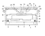
【図7】上記ディスクプレーヤ装置において光ディスク及びディスクスタビライザが装着された状態を示す正面図である。
【図8】上記ディスクプレーヤ装置において光ディスク及びディスクスタビライザが装着されていない状態を示す正面図である。
【図9】上記ディスクプレーヤ装置におけるローディング機構のローディングモータ及び減速ギヤを支持するための構成を示す縦断面図である。
【図10】上記ディスクプレーヤ装置において使用されるディスクスタビライザの形状を示す縦断面図である。
【図11】上記ディスクプレーヤ装置のディスクドライブ部の構成を示す平面図である。
【図12】上記ディスクドライブ部においてディスクテーブルが光学ピックアップ装置より離間された状態を示す平面図である。
【図13】上記ディスクドライブ部の構成を一部を破断して示す側面図である。
【図14】上記ディスクドライブ部の構成を示す正面図である。
【図15】上記ディスクドライブ部の構成を示す縦断面図である。
【図16】上記ディスクドライブ部における光学ピックアップ装置を支持するための構成の要部を示す分解斜視図である。
【図17】上記ディスクプレーヤ装置の動作を説明する流れ図である。
【符号の説明】
3 スラスト軸受け
7 トレイ部
8 第1のシャフト
11 トレイカバー
12 ディスクスタビライザ
24 発光素子
25 受光素子
26 ローディングモータ
43 軸受け孔
60 光学ピックアップ装置
61 ディスクテーブル
70 表示パネル
71 前面パネル
72 底板部
73 スピンドル軸
95 スレッドモータ
104 支持ブロック
201 光ディスク[0001]
[Industrial applications]
The present invention relates to a disc player device that reads out and reproduces information signals recorded on an optical disc.
[0002]
[Prior art]
2. Description of the Related Art Conventionally, there has been proposed a disc player device which reads out an information signal recorded on an optical disc by an optical pickup device, demodulates the information signal into an acoustic signal, and reproduces the signal.
[0003]
Such a disk player device is configured to have a loading mechanism for loading an optical disk into an outer housing and a chucking mechanism for mounting the loaded optical disk on a disk table.
[0004]
The loading mechanism has a disk tray that is operated to move inside and outside the outer housing. The disc tray is positioned and mounted on the optical disc while being moved to the outside of the outer casing. Then, the disc tray is moved into the outer casing while the optical disc is placed, so that the optical disc is carried into the outer casing.
[0005]
The chucking mechanism includes the disk table constituting a disk drive unit, and a rotatable chucking plate disposed opposite to the disk table.
[0006]
The disk drive unit includes the optical pickup device and a spindle motor having the disk table mounted on a drive shaft. The optical pickup device is configured to be movable in the disk drive section in the direction of contacting and separating from the disk table.
[0007]
The disk drive is operable to move in a direction to move the disk table toward and away from the chucking plate. The optical disk carried in by the disk tray is located between the disk table and the chucking plate. When the disk table is moved to the chucking plate side after the optical disk is loaded, the disk table and the chucking plate cooperate to hold and hold the optical disk.
[0008]
When the spindle motor is driven to rotate, the disk table is rotated with the optical disk and the chucking plate. An information signal is read from the optical disk that is being rotated by the optical pickup device.
[0009]
[Problems to be solved by the invention]
By the way, in the above-described disc player device, after the loading of the optical disc by the loading mechanism is completed, chucking of the optical disc is performed. Therefore, in this disc player device, it is difficult to reduce the time from when the optical disc is placed on the disc tray to when the reproduction of the optical disc is executed.
[0010]
Here, a configuration is conceivable in which the disk drive is mounted on the disk tray and the disk drive is moved to the outside of the outer casing. That is, if the disk drive unit is moved to the outside of the outer housing and the optical disk is mounted on the disk drive unit, when the disk drive unit is loaded into the outer housing, The reproduction operation can be executed immediately.
[0011]
However, if the disk drive is moved by the disk tray, it is difficult to attach and detach the optical disk to and from the disk drive unless the disk drive is moved sufficiently to the outside of the outer casing. Become. That is, the disk drive unit needs to be moved to the outside of the outer housing so that the entire surface of the optical disk mounted in the disk drive unit is positioned outside the outer housing.
[0012]
In order to support the disk drive so that the disk drive can be moved and operated over a sufficient distance, a robust structure that can sufficiently support the weight of the disk drive is required. This leads to an increase in the size and weight of the entire disc player device.
[0013]
Therefore, the present invention has been proposed in view of the above-described circumstances, and the disk drive unit has been sufficiently moved to the outer side of the outer housing while suppressing an increase in the size and weight of the device configuration. It is another object of the present invention to provide a disk player device capable of quickly attaching and detaching a recording disk to and from the disk drive unit.
[0014]
[Means for Solving the Problems]
In order to solve the above problems and achieve the above object, the disk player device according to the present invention is capable of moving operation over a position housed in an outer housing and a position protruding outward from the outer housing. A tray unit supported on the tray unit, a pickup device fixedly disposed on the tray unit, first driving means for moving the tray unit, and the pickup device disposed on the tray unit. A disk table which is provided on the outer side of the set position and is movably supported in the direction of contact and separation with respect to the pickup device, on which a recording disk is mounted, and which is rotated with the recording disk; When the means moves the tray to a position protruding from the outer casing, the outer casing within a range in which the disc table can be moved relative to the tray. And a second driving means for moving the operation more farthest position.
[0015]
In addition, the disc player device according to the present invention includes a tray portion movably supported over a position housed in an outer housing and a position protruding outward from the outer housing; A pickup device fixedly disposed above, first driving means for moving and operating the tray section, and a recording disk supported on the tray section so as to be movable in a direction of approaching and separating from the pickup apparatus; The disk table is mounted and rotated with the recording disk, and the disk table is moved to the position where the tray section is moved to a position stored in the outer housing by the first drive means. A second driving unit is provided on the inner peripheral side of the recording disk on which the pickup device is moved to a position where the pickup device is opposed to the recording disk.
[0016]
According to the present invention, in each of the above-described disc player devices, the tray is substantially movable by a shaft attached to the tray being movably supported by a thrust bearing provided in an outer housing. The shaft can be moved over a distance corresponding to the length of the tray portion, and the shaft has a length substantially twice as long as the length of the tray portion, and has one end outside the tray portion. The thrust bearing is located in the vicinity of the front end facing the outer side of the housing, the other end protruding rearward of the tray portion, and attached to the tray portion. The shaft is supported at a position near the front end of the tray portion and at a position near the rear end of the tray portion when stored in the tray.
[0017]
Further, according to the present invention, in each of the above disk player devices, the disk table has a spindle shaft, and the spindle shaft is attached to a support block disposed on a tray portion so as to be movable in a direction of approaching and separating from the pickup device. The support block is rotatably supported and provided, and the support block is integrally formed of a conductive material.
[0018]
[Action]
In the disc player device according to the present invention, the second driving means for moving the disc table on the tray is operated when the tray is moved to a position protruding from the outer housing by the first driving means. Since the disk table is moved to a position farthest from the outer casing within a range where the tray section can be moved, the projecting distance of the table part from the outer casing is shortened. The recording disk can be easily attached to and detached from the disk table.
[0019]
Further, in the disc player device according to the present invention, the second driving means for moving the disc table on the tray section is operated to move the tray section to a position where the tray section is stored in the outer casing by the first driving section. When this is done, the disk table is moved to the position closest to the pickup device within a range where the movement operation with respect to the tray portion is possible, so that the recording disk is mounted on the tray portion, and The time until the reproduction operation is performed is reduced.
[0020]
In each of the above-described disc player devices, the tray section is substantially the same length as the tray section by a shaft attached to the tray section being movably supported by a thrust bearing provided in the outer casing. The shaft has a length substantially twice as long as the length of the tray, and one end of the shaft has the outer casing of the tray. The thrust bearing is located near the front end facing outward and has the other end protruding rearward of the tray, and is attached to the tray. When the shaft is supported at a position near the front end of the tray portion and a position near the rear end of the tray portion when housed in the housing, the tray portion is Even in a state of being operated to move outward side of the housing, it is rigidly supported.
[0021]
Further, in each of the above-described disc player devices, the disc table has a spindle shaft, and the spindle shaft is rotatably supported by a support block disposed on a tray portion so as to be movable in a direction toward and away from the pickup device. When the support block is integrally formed of a conductive material, the disc table is disposed on the outer housing via the support block. Since it is electrically conducted, static electricity does not accumulate.
[0022]
【Example】
Hereinafter, specific embodiments of the present invention will be described with reference to the drawings.
[0023]
In this example, as shown in FIG. 1, a disc player device according to the present invention is configured as a device for reproducing an
[0024]
The
[0025]
[1] Configuration of chassis frame
As shown in FIG. 1, the disc player device has a
[0026]
As shown in FIG. 2, the
[0027]
A
[0028]
A
[0029]
[2] Configuration of tray section
On the
[0030]
The
[0031]
As shown in FIG. 2, the
[0032]
That is, the
[0033]
The
[0034]
A front
[0035]
The
[0036]
A front
[0037]
The
[0038]
When the
[0039]
The second thrust bearing 4 has a
[0040]
The second thrust bearing 4 supports the
[0041]
A through
[0042]
[3] Configuration of first driving means
The
[0043]
The loading
[0044]
That is, the
[0045]
The loading
[0046]
The
[0047]
The
[0048]
That is, the
[0049]
A
[0050]
An upper end portion of the
[0051]
As shown in FIGS. 4 to 6, a
[0052]
The
[0053]
The guide slit 78 is formed so as to be parallel to the
[0054]
When the
[0055]
At this time, the tip side of the
[0056]
When the
[0057]
When the
[0058]
When the
[0059]
The
[0060]
When the
[0061]
Then, as shown in FIG. 5, when the front end position of the linear portion of the
[0062]
When the
[0063]
[4] Configuration of disk drive unit
The
[0064]
As shown in FIGS. 11 to 15, the
[0065]
That is, the
[0066]
The
[0067]
The
[0068]
As shown in FIG. 14, the optical block portion is attached to the edge of the through
[0069]
The
[0070]
As shown in FIGS. 13 and 15, the disc table 61 has a substantially disk-shaped table portion, and has a substantially truncated conical centering
[0071]
The
[0072]
The
[0073]
The drive current of the spindle motor is supplied to the
[0074]
Then, the
That is, the
[0075]
The
As shown in FIG. 16, on one side of the
[0076]
The
[0077]
A
[0078]
The
[0079]
A
[0080]
The
As shown in FIG. 7, the disk table 61 has the center portion of the
[0081]
As shown in FIG. 10, the
[0082]
When the spindle motor is driven to rotate while the disk table 61 holds the
[0083]
As shown in FIG. 11, when the disk table 61 is located at the position closest to the
[0084]
As shown in FIG. 12, when the disc table 61 is located at the most distant position from the
[0085]
A thread-in switch and a thread-out switch (not shown) are attached to the
[0086]
The thread-in switch is pressed by the
[0087]
The thread-out switch is pressed by the
[0088]
The
[0089]
[5] Configuration of detection means of disk stabilizer
Detecting means for detecting the presence / absence of the
[0090]
As shown in FIG. 2, the light beam K from the
[0091]
When the
[0092]
That is, the
[0093]
[6] Operation of disc player device
In the disk player device according to the present invention configured as described above, the control circuit controls the first and second driving units, the rotation operation of the disk table 61, and the
[0094]
The control means, as indicated by an arrow A in FIG. 3, when the first drive means moves the
[0095]
Therefore, in this disc player apparatus, the disc table 61 is replaced with the disc table 61 while minimizing the amount of protrusion of the
[0096]
When the first drive unit moves the
[0097]
Therefore, in this disc player device, after the
[0098]
When the
[0099]
Further, when the
[0100]
Therefore, in this disc player apparatus, the disc table 61 is not rotated without the
[0101]
Further, since the
[0102]
The
[0103]
At this time, as shown by an arrow E in FIG. 2, the disc table 61 is moved in a direction away from the
[0104]
Further, the control circuit is configured to move the disk table 61 with respect to the
[0105]
That is, when the reproducing operation on the
[0106]
In step st3, it is determined whether or not the thread-in switch has been pressed. If the thread-in switch has been pressed, the process proceeds to step st4, and if not, the process proceeds to step st7.
[0107]
In step st4, the
[0108]
In step st5, it is determined whether or not the
[0109]
In step st6, the disc table 61 is moved in a direction away from the optical pickup device 60 (thread feed (outward direction)) until the thread-out switch is pressed, and the time limit is set. The timer for counting is reset, and the process returns to step st2.
[0110]
The timer is in a reset state at the beginning of the operation, that is, when the
[0111]
In step st9, the timer is reset, and the process proceeds to step st10 and returns.
[0112]
When the
[0113]
Then, in step st7, it is determined whether or not the time limit counted by the timer has elapsed. If the time limit has elapsed, the process proceeds to step st8. If the time limit has not elapsed, the process returns to step st3.
[0114]
In step st8, the
[0115]
By the operation from step st7 to step st8, when the operation of moving the disk table 61 in the direction approaching the
[0116]
In step st11, it is determined whether or not an operation of moving the disk table 61 in a direction away from the optical pickup device 60 (thread feeding (outward direction)) is being performed. If the operation of moving the disk table 61 in the direction away from the
[0117]
In step st12, it is determined whether or not the thread-out switch has been pressed. If the thread-out switch has been pressed, the process proceeds to step st13, and if not, the process proceeds to step st15.
[0118]
In step st13, the
[0119]
In step st14, the timer is reset, and the process proceeds to step st10 and returns.
[0120]
Then, in step st15, it is determined whether or not the time limit counted by the timer has elapsed. If the time limit has elapsed, the process proceeds to step st16. If the time limit has not elapsed, the process returns to step st12.
[0121]
In step st16, a moving operation of the disc table 61 in a direction approaching the optical pickup device 60 (thread feed (inward)) is performed for a predetermined time, and the process proceeds to step st17.
[0122]
In step st17, the operation of moving the disk table 61 in a direction away from the optical pickup device 60 (thread feed (outward direction)) is performed until the thread out switch is pressed, and the process returns to step st12. .
[0123]
By the operation from step st15 to step st17, when the operation of moving the disc table 61 in the direction away from the
[0124]
In the disc player device according to the present invention, the detecting means for detecting the presence or absence of the
[0125]
【The invention's effect】
As described above, in the disc player device according to the present invention, the second driving means for moving the disc table on the tray portion is located at a position where the tray portion projects from the outer housing by the first driving means. When the disk table is moved, the disk table is moved to a position farthest from the outer housing within a range where the movement operation with respect to the tray portion is possible.
[0126]
Therefore, in this disk player device, it is possible to easily attach and detach the recording disk to and from the disk table while shortening the projecting distance of the table portion from the outer casing.
[0127]
Further, in the disc player device according to the present invention, the second driving means for moving the disc table on the tray section is operated to move the tray section to a position where the tray section is stored in the outer casing by the first driving section. When the disc table is moved, the disc table is moved to a position closest to the pickup device within a range in which the disc table can be moved.
[0128]
Therefore, in this disk player device, the time from when the recording disk is mounted on the tray unit to when the reproducing operation on the recording disk is executed can be reduced.
[0129]
In each of the above-described disc player devices, the tray section is substantially the same length as the tray section by a shaft attached to the tray section being movably supported by a thrust bearing provided in the outer casing. The shaft has a length substantially twice as long as the length of the tray, and one end of the shaft has the outer casing of the tray. The thrust bearing is located near the front end facing outward and has the other end protruding rearward of the tray, and is attached to the tray. When the shaft is supported at a position near the front end of the tray portion and a position near the rear end of the tray portion when housed in the housing, the tray portion is Even in a state where the moving operation on the outer side of the body, it is possible to rigidly support the tray portion.
[0130]
Further, in each of the above-described disc player devices, the disc table has a spindle shaft, and the spindle shaft is rotatably supported by a support block disposed on a tray portion so as to be movable in a direction toward and away from the pickup device. When the support block is integrally formed of a conductive material, the disk table is electrically connected to an outer housing via the support block. And the accumulation of static electricity on the disk table can be prevented.
[0131]
That is, according to the present invention, while suppressing an increase in the size and weight of the device configuration, the disk drive unit is sufficiently moved to the outer side of the outer casing, and the recording disk can be quickly attached to and detached from the disk drive unit. It is possible to provide a disk player device that can be used.
[Brief description of the drawings]
FIG. 1 is an exploded perspective view showing a configuration of a disc player device according to the present invention.
FIG. 2 is a plan view showing a configuration of a tray portion of the disc player device, with a part thereof cut away.
FIG. 3 is a plan view, partially broken away, showing a state in which the tray section has been moved to the outside of an outer housing in the disc player device.
FIG. 4 is a partially cutaway plan view showing a configuration of a loading mechanism for moving the tray section in the disc player device.
FIG. 5 is a plan view, partially broken away, showing a state in which the loading mechanism is moving the tray in the disc player device.
FIG. 6 is a partially cutaway plan view showing a state in which the loading mechanism has moved the tray portion to the outside of the outer casing in the disc player device.
FIG. 7 is a front view showing a state where an optical disk and a disk stabilizer are mounted in the disk player device.
FIG. 8 is a front view showing a state where the optical disk and the disk stabilizer are not mounted in the disk player device.
FIG. 9 is a longitudinal sectional view showing a configuration for supporting a loading motor and a reduction gear of a loading mechanism in the disc player device.
FIG. 10 is a longitudinal sectional view showing a shape of a disk stabilizer used in the disk player device.
FIG. 11 is a plan view showing a configuration of a disk drive unit of the disk player device.
FIG. 12 is a plan view showing a state where the disk table is separated from the optical pickup device in the disk drive section.
FIG. 13 is a side view showing the structure of the disk drive unit, with a part thereof broken away.
FIG. 14 is a front view showing a configuration of the disk drive unit.
FIG. 15 is a longitudinal sectional view showing a configuration of the disk drive unit.
FIG. 16 is an exploded perspective view showing a main part of a configuration for supporting an optical pickup device in the disk drive unit.
FIG. 17 is a flowchart illustrating the operation of the disc player device.
[Explanation of symbols]
3 Thrust bearing
7 tray section
8 First shaft
11 Tray cover
12 disk stabilizer
24 light emitting element
25 light receiving element
26 Loading motor
43 Bearing hole
60 Optical pickup device
61 disk table
70 Display panel
71 Front panel
72 bottom plate
73 spindle shaft
95 thread motor
104 Support block
201 Optical Disk
Claims (4)
上記トレイ部上に固定して配設されたピックアップ装置と、
上記トレイ部を移動操作する第1の駆動手段と、
上記トレイ部上において上記ピックアップ装置が配設された位置よりも外方側に設けられ、該ピックアップ装置に対する接離方向に移動操作可能に支持され、記録ディスクが載置され、上記記録ディスクと共に回転操作されるディスクテーブルと、
上記第1の駆動手段が上記トレイ部を上記外筐体より突出される位置に移動操作するときには、上記ディスクテーブルを該トレイ部に対する移動操作が可能な範囲内における該外筐体より最も離間する位置に移動操作させる第2の駆動手段とを備えるディスクプレーヤ装置。A tray portion movably supported over a position housed in the outer housing and a position protruding outward from the outer housing,
A pickup device fixedly arranged on the tray section,
First driving means for moving the tray section,
The pickup device is provided on the tray portion outside the position where the pickup device is provided, is supported so as to be movable in the direction of approaching and separating from the pickup device, and a recording disk is placed thereon and rotates together with the recording disk. An operated disk table;
When the first drive means moves the tray unit to a position protruding from the outer housing, the disk table is furthest away from the outer housing within a range where the moving operation with respect to the tray unit is possible. And a second driving means for moving the disk player to a position.
上記トレイ部上に固定して配設されたピックアップ装置と、
上記トレイ部を移動操作する第1の駆動手段と、
上記トレイ部上において上記ピックアップ装置に対する接離方向に移動操作可能に支持され、記録ディスクが載置され、上記記録ディスクと共に回転操作されるディスクテーブルと、
上記第1の駆動手段により上記トレイ部を上記外筐体内に収納される位置に移動操作するときには、上記ディスクテーブルを該ディスクテーブルに載置される記録ディスクの内周側に上記ピックアップ装置が対向する位置まで移動操作させる第2の駆動手段とを備えるディスクプレーヤ装置。A tray portion movably supported over a position housed in the outer housing and a position protruding outward from the outer housing,
A pickup device fixedly arranged on the tray section,
First driving means for moving the tray section,
A disk table that is supported on the tray unit so as to be movable in the direction of contact and separation with respect to the pickup device, on which a recording disk is mounted, and that is rotated with the recording disk;
When the first drive means moves the tray section to a position where the tray section is stored in the outer casing, the pickup device faces the inner peripheral side of the recording disk mounted on the disk table. A second driving means for performing a moving operation to a position to be moved.
上記シャフトは、上記トレイ部の長さの略々2倍の長さを有し、一端部をこのトレイ部の上記外筐体の外方側に向いた前端部の近傍に位置させ他端側をこのトレイ部の後方側に突出させて該トレイ部に取り付けられ、
上記スラスト軸受けは、上記トレイ部が上記外筐体内に収納されているときにおけるこのトレイ部の前端部近傍の位置及びこのトレイ部の後端部近傍の位置において上記シャフトを支持することとなされた請求項1、または、請求項2記載のディスクプレーヤ装置。The tray section is moved over a distance substantially equivalent to the length of the tray section by a shaft attached to the tray section being movably supported by a thrust bearing provided in the outer housing. Operable,
The shaft has a length substantially twice as long as the length of the tray, and has one end positioned near a front end of the tray facing the outer side of the outer housing. Is attached to the tray by projecting it to the rear side of the tray,
The thrust bearing is adapted to support the shaft at a position near the front end of the tray portion and a position near the rear end of the tray portion when the tray portion is stored in the outer housing. The disc player device according to claim 1 or 2.
上記支持ブロックは、導電性材料により一体的に形成されている請求項1、請求項2、または、請求項3記載のディスクプレーヤ装置。The disk table has a spindle shaft, and the spindle shaft is rotatably supported by a support block disposed on a tray portion so as to be operable to move in a direction of approaching and separating from the pickup device,
4. The disc player device according to claim 1, wherein said support block is integrally formed of a conductive material.
Priority Applications (8)
| Application Number | Priority Date | Filing Date | Title |
|---|---|---|---|
| JP20211294A JP3551482B2 (en) | 1994-08-26 | 1994-08-26 | Disc player device |
| US08/518,559 US5621713A (en) | 1994-08-26 | 1995-08-23 | Disc player apparatus |
| EP95113339A EP0698882B1 (en) | 1994-08-26 | 1995-08-24 | Disc player apparatus |
| DE69513108T DE69513108T2 (en) | 1994-08-26 | 1995-08-24 | Disk player |
| TW84108824A TW381252B (en) | 1994-08-26 | 1995-08-24 | Disc player apparatus |
| MYPI95002539A MY116366A (en) | 1994-08-26 | 1995-08-25 | Disc player apparatus |
| KR1019950026677A KR100366140B1 (en) | 1994-08-26 | 1995-08-26 | Disc Player Device |
| CNB951163914A CN1181491C (en) | 1994-08-26 | 1995-08-26 | Information disc player apparatus |
Applications Claiming Priority (1)
| Application Number | Priority Date | Filing Date | Title |
|---|---|---|---|
| JP20211294A JP3551482B2 (en) | 1994-08-26 | 1994-08-26 | Disc player device |
Publications (2)
| Publication Number | Publication Date |
|---|---|
| JPH0863851A JPH0863851A (en) | 1996-03-08 |
| JP3551482B2 true JP3551482B2 (en) | 2004-08-04 |
Family
ID=16452167
Family Applications (1)
| Application Number | Title | Priority Date | Filing Date |
|---|---|---|---|
| JP20211294A Expired - Fee Related JP3551482B2 (en) | 1994-08-26 | 1994-08-26 | Disc player device |
Country Status (7)
| Country | Link |
|---|---|
| US (1) | US5621713A (en) |
| EP (1) | EP0698882B1 (en) |
| JP (1) | JP3551482B2 (en) |
| KR (1) | KR100366140B1 (en) |
| CN (1) | CN1181491C (en) |
| DE (1) | DE69513108T2 (en) |
| MY (1) | MY116366A (en) |
Families Citing this family (24)
| Publication number | Priority date | Publication date | Assignee | Title |
|---|---|---|---|---|
| JP2860275B2 (en) * | 1995-07-28 | 1999-02-24 | 株式会社ケンウッド | Recording medium playback device |
| KR980004506A (en) * | 1996-06-29 | 1998-03-30 | 김광호 | The pickup tilt adjustment device of the disc player |
| KR19980020837A (en) * | 1996-09-12 | 1998-06-25 | 구자홍 | Disc mounting member moving device of disc player |
| JPH10214452A (en) | 1997-01-30 | 1998-08-11 | Toshiba Corp | Rotary device and information processor using the same |
| US6941566B2 (en) * | 1997-03-10 | 2005-09-06 | Mitsubishi Electric Engineering Company Limited | Disc system |
| US6169712B1 (en) | 1997-03-14 | 2001-01-02 | Kabushiki Kaisha Kenwood | Reproducing apparatus for recorded medium |
| US6459674B1 (en) | 1997-07-24 | 2002-10-01 | Matsushita Electric Industrial Co., Ltd. | Disc changer apparatus with vibration free turntable |
| JP3536599B2 (en) | 1997-07-24 | 2004-06-14 | 松下電器産業株式会社 | Disc changer device |
| JPH11213513A (en) * | 1998-01-26 | 1999-08-06 | Teac Corp | Recording medium loading device |
| JP4196514B2 (en) * | 2000-02-08 | 2008-12-17 | ミツミ電機株式会社 | Disk unit |
| US6603723B2 (en) * | 2000-07-28 | 2003-08-05 | Teac Corporation | Recording medium loading device |
| US7330638B2 (en) * | 2001-08-02 | 2008-02-12 | Warner Bros. Home Entertainment Inc. | Apparatus generating content codes for audiovisual programs |
| US7231131B2 (en) * | 2001-08-02 | 2007-06-12 | Warner Bros. Home Entertainment Inc. | Apparatus for generating content codes for audiovisual programs by multiple viewers |
| JP3866953B2 (en) * | 2001-10-02 | 2007-01-10 | パイオニア株式会社 | Recording medium playback device |
| KR100493034B1 (en) * | 2002-11-13 | 2005-06-07 | 삼성전자주식회사 | Slim type optic disc drive |
| KR100505652B1 (en) * | 2002-11-27 | 2005-08-03 | 삼성전자주식회사 | Slim type optic disc drive |
| KR100505653B1 (en) * | 2002-11-28 | 2005-08-03 | 삼성전자주식회사 | Slim type optic disc drive |
| KR20060034243A (en) | 2003-06-30 | 2006-04-21 | 코닌클리케 필립스 일렉트로닉스 엔.브이. | Disk drive with improved tray control |
| JP2005038483A (en) * | 2003-07-17 | 2005-02-10 | Sharp Corp | Method for loading and unloading disk recording medium, and disk drive unit |
| KR100503809B1 (en) * | 2003-09-17 | 2005-07-26 | 삼성전자주식회사 | Disk drive |
| US20050108741A1 (en) * | 2003-11-19 | 2005-05-19 | Cookson Christopher J. | Disc drive or player for reading double-sided optical discs |
| JP2006172673A (en) * | 2004-12-20 | 2006-06-29 | Orion Denki Kk | Video recording and reproducing device |
| JP4407574B2 (en) * | 2005-06-23 | 2010-02-03 | 船井電機株式会社 | Disk unit |
| JP6452070B2 (en) * | 2014-12-22 | 2019-01-16 | エッセイジー システム サービス エス.アール.エル. | Improved storage unit |
Family Cites Families (11)
| Publication number | Priority date | Publication date | Assignee | Title |
|---|---|---|---|---|
| NL8303217A (en) * | 1983-09-19 | 1985-04-16 | Philips Nv | OPTICAL RECORD PLAYER. |
| JPS6424785U (en) * | 1987-07-31 | 1989-02-10 | ||
| JPS6486356A (en) * | 1987-09-28 | 1989-03-31 | Toshiba Corp | Driving mechanism for disk reproducing device |
| KR910007430B1 (en) * | 1989-05-31 | 1991-09-26 | 삼성전자 주식회사 | Twin disk player |
| JP2692290B2 (en) * | 1989-08-31 | 1997-12-17 | ソニー株式会社 | Disc recording and / or playback device |
| US5216558A (en) * | 1991-01-30 | 1993-06-01 | Iomega Corporation | Drawer loading removable cartridge disk drive |
| JPH04345953A (en) * | 1991-05-24 | 1992-12-01 | Pioneer Electron Corp | Autoloading disk player |
| US5210737A (en) * | 1991-10-29 | 1993-05-11 | Hanpin Electron Co., Ltd. | Separable compact disc player with an elastic hold-down member |
| JPH05342732A (en) * | 1992-06-12 | 1993-12-24 | Sony Corp | Recording and/or reproducing apparatus for disk-shaped recording medium |
| JPH0668634A (en) * | 1992-08-24 | 1994-03-11 | Sony Corp | Disk device |
| JP3326626B2 (en) * | 1992-08-24 | 2002-09-24 | ソニー株式会社 | Disk unit |
-
1994
- 1994-08-26 JP JP20211294A patent/JP3551482B2/en not_active Expired - Fee Related
-
1995
- 1995-08-23 US US08/518,559 patent/US5621713A/en not_active Expired - Lifetime
- 1995-08-24 EP EP95113339A patent/EP0698882B1/en not_active Expired - Lifetime
- 1995-08-24 DE DE69513108T patent/DE69513108T2/en not_active Expired - Fee Related
- 1995-08-25 MY MYPI95002539A patent/MY116366A/en unknown
- 1995-08-26 CN CNB951163914A patent/CN1181491C/en not_active Expired - Fee Related
- 1995-08-26 KR KR1019950026677A patent/KR100366140B1/en not_active IP Right Cessation
Also Published As
| Publication number | Publication date |
|---|---|
| US5621713A (en) | 1997-04-15 |
| DE69513108T2 (en) | 2000-02-17 |
| MY116366A (en) | 2004-01-31 |
| EP0698882B1 (en) | 1999-11-03 |
| CN1181491C (en) | 2004-12-22 |
| KR100366140B1 (en) | 2003-03-12 |
| CN1140312A (en) | 1997-01-15 |
| DE69513108D1 (en) | 1999-12-09 |
| JPH0863851A (en) | 1996-03-08 |
| EP0698882A2 (en) | 1996-02-28 |
| EP0698882A3 (en) | 1996-06-19 |
| KR960008778A (en) | 1996-03-22 |
Similar Documents
| Publication | Publication Date | Title |
|---|---|---|
| JP3551482B2 (en) | Disc player device | |
| EP0863511B1 (en) | Recording and/or reproducing apparatus for recording medium and damper mechanism employed in such apparatus | |
| JP3154141B2 (en) | Buffer device and recording and / or reproducing device for disk-shaped recording medium using buffer device | |
| JPH06223471A (en) | Disk recording and/or reproducing device | |
| KR100305916B1 (en) | Disc Player Device | |
| US6711113B2 (en) | Disk drive apparatus | |
| JP3551483B2 (en) | Disc player device | |
| US7958520B2 (en) | Disk drive device | |
| JP3552289B2 (en) | Disc player device | |
| US6789260B2 (en) | Disk drive apparatus | |
| JPH0863854A (en) | Disc player apparatus | |
| KR100710397B1 (en) | Head feed mechanism for disk drive apparatus | |
| CN100464372C (en) | Disk drive device | |
| JPH0927184A (en) | Disk player device | |
| KR0146427B1 (en) | A swinging preventing device of mini disc player for a car | |
| JPH07114789A (en) | Recording and/or reproducing device and damper member | |
| JP2000331443A (en) | Transfer device for light pickup | |
| JPH05182439A (en) | Disk driving device | |
| JP3781783B2 (en) | Disc loading mechanism and disc recording / reproducing apparatus | |
| JP3503635B2 (en) | Magneto-optical recording / reproducing device | |
| JP3733623B2 (en) | Recording medium loading mechanism | |
| JPH0935385A (en) | Disk device and guiding method of turntable in disk device | |
| JPH097361A (en) | Disk player apparatus | |
| JP2000040289A (en) | Disk changer device | |
| JP2003317357A (en) | Disk device |
Legal Events
| Date | Code | Title | Description |
|---|---|---|---|
| A131 | Notification of reasons for refusal |
Free format text: JAPANESE INTERMEDIATE CODE: A131 Effective date: 20040106 |
|
| A521 | Written amendment |
Free format text: JAPANESE INTERMEDIATE CODE: A523 Effective date: 20040308 |
|
| TRDD | Decision of grant or rejection written | ||
| A01 | Written decision to grant a patent or to grant a registration (utility model) |
Free format text: JAPANESE INTERMEDIATE CODE: A01 Effective date: 20040406 |
|
| A61 | First payment of annual fees (during grant procedure) |
Free format text: JAPANESE INTERMEDIATE CODE: A61 Effective date: 20040419 |
|
| FPAY | Renewal fee payment (event date is renewal date of database) |
Free format text: PAYMENT UNTIL: 20080514 Year of fee payment: 4 |
|
| FPAY | Renewal fee payment (event date is renewal date of database) |
Free format text: PAYMENT UNTIL: 20090514 Year of fee payment: 5 |
|
| FPAY | Renewal fee payment (event date is renewal date of database) |
Free format text: PAYMENT UNTIL: 20100514 Year of fee payment: 6 |
|
| LAPS | Cancellation because of no payment of annual fees |