JP3540577B2 - FM multiplex broadcast receiving device - Google Patents
FM multiplex broadcast receiving device Download PDFInfo
- Publication number
- JP3540577B2 JP3540577B2 JP30044597A JP30044597A JP3540577B2 JP 3540577 B2 JP3540577 B2 JP 3540577B2 JP 30044597 A JP30044597 A JP 30044597A JP 30044597 A JP30044597 A JP 30044597A JP 3540577 B2 JP3540577 B2 JP 3540577B2
- Authority
- JP
- Japan
- Prior art keywords
- frame
- detection
- frame synchronization
- data
- circuit
- Prior art date
- Legal status (The legal status is an assumption and is not a legal conclusion. Google has not performed a legal analysis and makes no representation as to the accuracy of the status listed.)
- Expired - Fee Related
Links
Images


Landscapes
- Time-Division Multiplex Systems (AREA)
- Synchronisation In Digital Transmission Systems (AREA)
Description
【0001】
【発明の属する技術分野】
本発明はFM放送にデータが多重されたFM多重放送を受信するFM多重放送の受信装置に関し、特に、フレーム同期方式の選択制御に関する。
【0002】
【従来の技術】
一般に、FM放送に文字情報等を多重して放送するFM多重放送が行われている。このFM多重放送では、文字放送を符号化してFMステレオ放送に多重しており、現在では、ニュースや交通情報等の番組が放送されている。
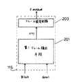
現在、日本国内でFM多重放送の本放送(商業放送)が行われている。このFM多重によれば、多重データのフレーム構成は図13のように、288×272ビットのフレームとなり、基本的に1フレームの1ブロック(1フレーム中の1行)は、16ビットのブロック識別コード(BIC)、176ビットのデータパケット及び96ビット誤り訂正符号(14ビットのCRC、82ビットの水平パリティ)から構成されているものと、16ビットのBIC及び272ビットの誤り訂正符号(垂直パリティ)から構成されているものから成る。このフレーム構成は、ITU(International Telecommunication Union:国際電気通信連合)の勧告により、「method B」と定義され、さらに、ITU勧告では「method B」の他に、それとフレーム構成が異なる「method A」、「method A'」及び「method C」の3種類のフレーム構成が定義されている。その為、FM多重放送では、4種類のフレーム構成が国際標準規格となっている。尚、現在、欧州のSWIFT(System for Wireless Infotainment Forwarding and Teledistribution)の規格(最終ドラフト)では、上記の「method A」、「method A'」、「method B」及び「method C」はそれぞれ「method A0」、「method A1」、「method B」及び「method C」と定義され、欧州のRDS(Radio Data System)で使用されているような、現在の受信局と同一のネットワークの局であって、前記受信局と同一番組を放送する放送局の周波数リスト(代替周波数リスト、以下AFリストという)のデータや現行の放送局のフレーム構成のデータ(以下、フレームタイプデータFTという)を多重データに含ませることも提案されている。
【0003】
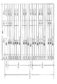
また、「method A」、「method A'」及び「method C」のフレーム構成はそれぞれ図11、12及び14にようになる。「method A」のフレーム構成は、288×272ビットのフレームになり、一つのブロック構成は「method B」とそれぞれ同じだが、データパケットを含むブロックと誤り訂正符号のみを含むブロックとが区別されて配置されている。また、「method A'」のフレーム構成は、「method A」の誤り訂正符号のみを含む部分に12ブロックの「REAL TIME INFORMATION BLOCK」が挿入されて構成されている。さらに、「method C」のフレーム構成は288ビットのデータパケットを含むブロックのみにより構成される。
【0004】
【発明が解決しようとする課題】
現在は、日本でのみFM多重放送が行われているが、今後は欧州や米国でもFM多重放送が行われる予定がある。特に、欧州では、今後広い意味での日本の方式によるFM多重放送のサービスが行われる予定があるものの、欧州のFM多重放送のフレーム構成は、日本で使用されているフレーム構成と異なり、4つの異なるフレーム構成が採用される方向である。しかし、欧州では、FM多重放送が各地域で採用され、放送が行われたとしても、国や地域ごとにフレーム構成が異なる可能性は十分にあり、さらに放送局ごとに採用されるフレーム構成が異なる可能性もある。その為、受信局を変更したとき、変更に追従してFM多重データも素速く得ることが求められる。
【0005】
そこで、本発明は、受信局を変更した際、素速くかつ正確なフレーム同期を行うことが可能なFM多重放送の受信制御装置を提供することを目的とする。
【0006】
【課題を解決するための手段】
本発明は、FM多重放送から多重データを復調するFM多重受信装置において、複数のフレーム同期手段を有し、前記複数のフレーム同期手段のうち1つのフレーム同期手段により前記多重データのフレーム同期を行うフレーム同期回路と、前記多重データに含まれるフレームタイプデータを検出する第1検出手段、及び該第1検出手段の出力信号に応じて前記複数のフレーム同期手段を切り換える切換手段を含む制御回路と、を備えることを特徴とする。
【0007】
さらに、前記制御回路は、前記複数のフレーム同期手段を順次切り換え、切り換えられたフレーム同期手段によって、フレーム同期が確立したことを検出する第2検出手段とを備え、前記第1検出手段または前記第2検出手段の検出結果に基づきフレーム同期手段を選択することを特徴とする。
前記制御回路は、前記第1及び第2検出手段の検出結果のうち、早く検出された結果によって前記フレーム同期手段を選択することを特徴とする。
【0008】
また、前記制御回路は、第1及び第2検出手段の検出結果を比較する比較手段とを備え、両方の検出結果が一致したとき一致する検出結果に基づきフレーム同期手段を選択することを特徴とする。
前記制御回路は、前記両方の検出結果が不一致のとき、再度第1検出手段及び/または第2検出手段を動作させることを特徴とする。
【0009】
さらにまた、前記制御回路は、前記両方の検出結果が不一致のとき、両方の検出結果のうち優先度の高い検出結果を選択することを特徴とする。
特に、第2検出手段の検出結果の優先度を高くすることを特徴とする請求項6記載のFM多重放送の受信装置。
また、記複数のフレーム同期手段に優先度を付け、前記第1及び第2検出手段の検出結果のうち優先度の高いフレーム同期手段によって、前記複数のフレーム同期手段のうち一つを選択することを特徴とする請求項6記載のFM多重放送の受信装置。
【0010】
本発明によれば、多重データに含まれるフレームタイプデータにより、現行の放送局のフレーム構成を検出し、その検出結果に応じてフレーム同期回路における複数のフレーム同期手段のうち1つのフレーム同期手段に切り換える。また、複数のフレーム同期手段を順次切り換え、切り換える毎に受信FM多重放送中のフレーム構成にフレーム同期手段がフレーム同期したか検出され、フレームタイプデータによるフレーム同期手段と、フレーム同期手段の切換によるフレーム同期手段とに基づいて、複数のフレーム同期手段を切り換える。
【0011】
【発明の実施の形態】
図1は本発明の実施の形態を示す回路である。101はIF信号を出力するFM同調用のフロントエンド、102はIF信号をFMコンポジット信号に復調するFM復調回路、103はコンポジット信号をステレオ信号に復調するMPX(マルチプレクス)回路、104はステレオ信号を増幅し、スピーカ105に出力するAF増幅回路、106はFM同調用フロントエンド回路101の同調周波数を決定するためのPLL周波数シンセサイザ回路、107はFM多重データを復調するブロックであり、108は76KHzを中心周波数とするバンドパスフィルタ、109は多重データを復調するL−MSK復調回路、110は復調多重データのブロック同期を行うブロック同期回路、111は4つのフレーム同期方式を有しブロックデータのフレーム同期を行うフレーム同期回路、112はフレームが再構成されたデータに誤り訂正を行う誤り訂正回路、113は誤り訂正回路112の出力に応じて、1ブロック分のデータによって横方向訂正されたデータdata1と、1フレーム分のデータによって縦方向のエラー訂正も行われたデータdata2とを選択的に出力するデータ出力回路である。
【0012】
また、114は操作キー117によりPLL周波数シンセサイザ回路106を制御し同調周波数の変更を行う手段と、多重データの復号処理を行い、復号結果を表示ディスプレイ116に表示させる手段と、フレーム同期回路111のフレーム同期方式を切り換える切換信号Fmethodを出力するフレーム選択回路115を含む制御回路である。
【0013】
図1において、受信RF信号はFMフロントエンド101内で発生する局部発振信号により所定周波数のIF信号に周波数変換され、IF信号はFM復調回路102でコンポジット信号に復調される。コンポジット信号のうちオーディオ信号成分はMPX回路103で左右ステレオ信号にステレオ復調される。左右ステレオ信号はAF増幅回路104で増幅された後、スピーカ105に伝送される。
【0014】
また、コンポジット信号中のFM多重成分はBPF108を通過し、L−MSK復調回路109で多重データに復調される。ブロック同期回路110でブロック毎に多重データの同期がとられた後、フレーム同期回路111でフレーム毎に多重データの同期がとられ、ブロック及びフレーム同期がとられた多重データは誤り訂正回路112で誤り訂正される。誤り訂正を受けたデータDATAは制御回路113で復号され、復号データに基づき文字情報及び図形情報がディスプレイ116に表示される。
【0015】
FMフロントエンド101は局部発振回路(図示せず)を含み、局部発振信号の周波数はPLLシンセサイザー106からの周波数制御信号により変更されるとともに、局部発振信号はPLL周波数シンセサイザー106に出力される。局部発振回路はPLL周波数シンセサイザー106とともにPLLを形成し、PLLシンセサイザー106にはPLLの構成のうち基準信号を発生する基準発振回路、基準信号を分周するリファレンスディバイダ、局部発振信号を可変分周数で分周するプログラマブルディバイダ、上記2つのディバイダの出力を位相比較する位相比較回路及び位相比較回路の出力に応じて周波数制御信号を出力するループフィルタが構成される。尚、PLLについては周知の技術であるため動作説明は省略する。
【0016】
操作キー117により設定された放送局を受信しようとする場合、まず、この放送局の受信周波数に対応する分周データNdataが制御回路114から出力される。分周データNdataに応じてプログラマブルディバイダの可変分周数が設定され、局部発振信号の周波数は上記放送局に対応した周波数になる。その結果、上記放送局の受信RF信号が所定周波数のIF信号に変換され、放送局のオーディオ復調及び多重復調が行われる。このように、制御回路114はフロントエンド101の同調動作を制御する。
【0017】
ところで、フレーム選択回路115は、図2のように構成される。第1フレーム検出手段301は、ブロック同期回路110がブロック同期をしたことを示すロック信号Blockを取り込んだ後、図15に示されるようにデータdata1中に含まれたフレームタイプデータFT1を検出し、検出完了したときフラグFG1を出力する。フレームタイプデータFTは2ビットから成り、データの組み合わせによりフレーム構成の種類の検出が可能となるので、第1フレーム検出手段301はデータの組み合わせを検出してその組み合わせに応じてフレームタイプデータFT2を発生する。また、第2フレーム検出手段302は、フレーム同期回路111のフレーム同期手段を変える切換信号Fmethodを順次変更するように2ビットのフレームタイプを変えながら出力し、変更する毎にフレーム同期回路111がフレーム同期したことを示すロック信号Flockを検出して、ロック信号Flockの出力に応じて図5の如き2ビットのフレームタイプFT2及び検出完了を示すフラグFG2を出力する。フレーム設定手段は、データFT1及びFT2、かつ、フラグFG1及びFG2に応じて切換信号Fmethodを出力するフレーム設定手段303とから成る。
【0018】
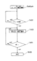
次に、図1のラジオ受信機のフレーム同期方式の自動切り換え動作を、図3のフローチャートに基づいて説明する。
まず、操作キー117を希望の受信局となるように操作し、分周データNdataが制御回路114から変更されて出力され、フロントエンド101の局部発振信号が変更されることにより、受信局が変更される(S1)。すると、フレーム設定手段303は第1及び第2フレーム選択手段301及び302からのフラグFG1及びFG2があるか否か検出する(S2)。しかし、受信局の変更直後は多重データの復調やフレームデータの検出が終了していないので、フラグFG1及びFG2は出力されない。その為、変更された受信局のフレームタイプを検出する動作に移る。
【0019】
フレームタイプの検出(S3及びS4)は、第1及び第2フレーム検出手段301及び302により同時並行して行われる。初めにS3の第1フレーム検出手段301によるフレーム検出を図4のフローチャートを参照して説明する。第1フレーム検出手段301はブロック同期回路110のロック信号Blockが入力されたか否かを検出する。つまり、ブロック同期回路110のブロック同期が取られたか否か確認される(S21)。ブロック同期が確認されるまで、第1フレーム検出手段301は待機状態になる。ブロック同期が確認されると、第1フレーム検出手段301はデータ出力回路113から出力されるデータdata1を復号し、さらにデータdata1に含まれるフレームタイプデータFTを検出する(S22)。続いて、データFTがあるか否かが確認される(S23)。データFT1が確認できない場合、S22に戻り、再びブロックデータdata1を復号し、データFT1の存在を確認する。また、データFT1がある場合、図4のフローチャートを終了する。そして、図3に戻り、第1フレーム検出手段301はフラグFG1をフレームタイプデータの検出を完了したことを示す状態「1」にセットする(S5)。
【0020】
一方、第2フレーム検出手段302のフレーム検出を図5のフローチャートを参照して説明する。第2フレーム検出手段302はフレームタイプFT2を設定し、これに対応するFmethodがフレーム設定手段303から出力される。Fmethodによりフレーム同期回路111のフレーム同期手段が切り換わる。尚、フレームタイプの変更は、例えば「method A0」→「method A1」→「method B」→「method C」→「method A0」の順で行われる。よって、最初にフレーム同期回路111のフレーム同期手段は「method A0」に設定される(S24)。その後、第2フレーム検出手段302は設定されたフレーム同期手段でフレーム同期がとられたか否か確認する。この確認は、フレーム同期回路111がフレーム同期に入ったときに出力されるロック信号Flockによって確認される(S25)。
【0021】
S25で、フレーム同期回路111が「method A0」で同期できなかった場合、第2フレーム検出手段302はフレームタイプFT2を変更し、フレーム同期手段を「method A1」に変更する(S26)。設定されたフレーム同期手段にフレーム同期がとれなければ、第2フレーム検出手段302は「method A0」〜「method C」のフレーム同期手段を順次変更する。S25において、フレーム同期がとられるフレーム同期方式が存在すれば、第2フレーム検出手段302内の内部メモリ(図示せず)に、フレーム同期可能なフレームタイプFT2が記憶される。その後、図5のフローチャートが終了し、図3に戻り、第2フレーム検出手段302はフラグFG2をフレームタイプFT2の検出を完了したことを示す状態「1」にセットする(S6)。
【0022】
フラグFG1またはフラグFG2に検出完了を示す「1」の状態が設定されると、フレーム設定手段303はフラグ有りと判定し(S2)、さらにフラグFG1が「1」の状態か否か判定される(S7)。フラグFG1が「1」の状態の場合、フレーム設定手段303は第1フレーム検出手段301のフレームタイプデータFT1に基づき信号Fmethodを出力する。Fmethodに応じて、フレーム同期回路111の同期検出手段は、多重データに含まれるフレームタイプデータに基づくフレーム同期手段に切り換わる(S8)。また、フラグFG1が「1」の状態でないと、フラグFG2が「1」の状態なのでフレーム設定手段303は第2フレーム検出手段302のフレームタイプFT2に基づいて信号Fmethodを出力する。Fmethodに応じて、フレーム同期回路111のフレーム同期手段は、実際に同期可能なフレーム同期手段に切り換わる。
【0023】
よって、図3のフローチャートでは、第1及び第2フレーム検出手段のうち早く検出された結果によって、フレーム同期手段が切り換わる。
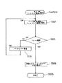
図6は本発明の他の実施の形態を説明する為のフローチャートである。受信局の変更(S1)後、図4及び図5のフローチャートに従って、それぞれ第1及び第2フレーム検出手段301及び202でフレームタイプを検出し(S3、S4)、検出完了したらフラグFG1及びFG2にそれを示す状態にそれぞれセットする(S5、S6)。
【0024】
その後、フレーム設定手段303は、S5でフラグFG1が「1」になった場合次にフラグFG2が「1」になることを判定し(S31)、また、S6でフラグFG2が「1」になった場合次にフラグFG1が「1」になることを判定する(S32)。両方のフラグFG1及びFG2が互いに「1」の状態になったことを確認すると、フレーム設定手段303はフレームタイプFT1とフレームタイプFT2とが一致するか否か判定する(S33)。フレームタイプFT1及びFT2が一致しない場合、S3及びS4に戻り、フレームタイプを再度検出する。また、一致した場合、フレーム設定手段303は一致したフレームタイプに基づき切換信号Fmethodを出力し、フレーム同期回路111のフレーム同期手段はFmethodに応じて切り換わる(S35)。
【0025】
さらに、図7は他の実施の形態を説明するためのフローチャートであり、図6のフローチャートと比べて、検出されたフレームタイプFT1及びFT2が不一致となった場合の動作が異なる。第1及び第2フレーム検出手段301及び302で検出されたフレームタイプFT1及びFT2が一致しない場合、フレーム設定手段303はフレームタイプFT2を優先し、フレームタイプFT2に基づいて切換信号Fmethodを出力する。Fmethodに応じて、フレーム同期回路111のフレーム同期手段は、実際に同期可能なフレーム同期手段に切り換わる(S35)。
【0026】
尚、図7のフローチャートでは、検出されたフレームタイプが不一致となる場合フレームタイプFT2を優先させているが、フレームタイプFT1を優先させてフレーム同期手段を切り換えてもよい。また、検出されたフレームタイプが不一致の場合フレームタイプFT1及びFT2の一方を優先させていたが、各々のフレームタイプ「method A0」〜「method C」に優先度を付け、検出されたフレームタイプ自体の優先度を比較し、優先度の高いフレームタイプによってフレーム同期手段を切り換えることも可能である。
【0027】
図8はフレーム選択回路115の他の構成例であり、第1フレーム検出手段301のみを含む。図8の動作を図9のフローチャートを参照して説明する。受信局を変更する(S1)と、図4のフローチャートに従って多重データからフレームタイプデータFT1を検出する(S3)。フレーム設定手段303は、フレームタイプFT1に基づいて切換信号Fmethodを出力し、Fmethodに応じてフレーム同期回路111のフレーム同期手段はフレームタイプデータに応じたフレーム同期手段に切り換わる。
【0028】
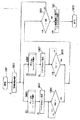
図10は、図1のブロック同期回路110、フレーム同期回路111、誤り訂正回路112及びデータ出力回路113の具体回路例を示すブロック図である。201は多重データ中に含まれるBICを検出するBIC検出回路、202は検出されたBICの変化点を検出する変化点検出回路、203は多重データのデータ数を1ブロックのデータ数分の288個カウントして、カウント完了すると完了信号を出力するデータカウンタ、204は完了信号をカウントすることによりブロック数をカウントするブロックカウンタ、205はフレーム構成中の所定の変化点を検出するとともに、ブロックカウンタ204のカウント値に基づき所定変化点の間のブロック数を検出することによりフレーム同期を検出するとともに、フレーム同期している最後尾のブロックを検出するとブロックカウンタ204をリセットするフレーム同期検出回路、206は288カウントの周期でデータカウンタ203の完了信号が入力される毎にBICが入力されたか検出し、所定のブロック数分のBICを検出できたら、ブロック同期したことを示すブロック同期検出信号Blockを出力するブロック同期回路である。
【0029】
また、207はライト・リードアドレス発生回路を含み、指定されたライト・リードアドレスに多重データが書き込み、読み出しされるフレームメモリ、208はフレーム同期検出信号Flockに応じてフレームの先頭に先頭フラグをつけて多重データをメモリ207に記憶させるタイミング回路、209は多重データをフレームメモリ207に保存するため、1ブロック毎に一時保存するブロックデータバッファ、210はデータバッファ209中の1ブロック分のデータを水平パリティにより誤り訂正し、メモリ207中の1フレーム分のデータを垂直パリティにより誤り訂正する誤り訂正回路、211はブロックデータバッファ209の出力データd1とフレームメモリ207の出力データd2とを選択的に出力するデータ出力部である。
【0030】
フレーム検出回路205は例えば多重データのフレーム構成が図11のフレーム構成「method B」の場合、所定の検出点、即ち、「BIC1→BIC3」、「BIC4→BIC2」、「BIC2→BIC3」、「BIC4→BIC1」及び「BIC1→BIC3」の変化点が順に繰り返されることを検出するとともに、上記それぞれの変化点の間のブロック数が123個、13個、123個及び13個となることを検出することによりフレーム同期を検出し、フレーム同期を検出するとフレーム同期検出信号Flockを出力する。また、フレーム同期検出回路205にはFmethodが印加され、このFmethodによってフレーム同期手段が切り換わる。具体的には、フレーム構成に応じてFmethodを変更することによってフレーム検出回路の構成が変化し、その結果、検出対象となる所定の変化点が変更され、繰り返される変化点の順番が変更される。さらに、変化点と変化点との間のカウントされるべき数が変更される。
【0031】
つまり、フレーム構成が「method A0」の場合、フレーム検出回路205は「BIC3→BIC2」、「BIC2→BIC1」、「BIC1→BIC4」、「BIC4→BIC3」及び「BIC3→BIC2」の変化点を検出するとともに、その間のブロック数が70個、60個、82個、60個となることを検出するように変更される。また、フレーム構成が「method A1」の場合、フレーム検出回路205は「BIC3→BIC2」、「BIC2→BIC1」、「BIC1→BIC4」、「BIC4→BIC3」及び「BIC3→BIC2」の変化点を検出するとともに、その間のブロック数が70個、60個、94個、60個となることを検出するように変更される。さらに、「method C」の場合、1ブロックごとに「BIC3→BIC3」に検出するように変化される。以上述べた如く、F methodを変えることにより、多重データのフレーム構成に対応したフレーム同期手段を変更することが可能になる。
【0032】
ブロック同期がとれた多重データは、検出信号Blockが出力されるタイミングでデータバッファ209に一時保存され、1ブロック毎に図11の如くデータに含まれた水平パリティによりエラー訂正が行われる。水平パリティのエラー訂正により多重データ中のエラーが訂正できた場合、データバッファ209からエラー訂正されたデータd1が出力され、データ出力部211を介して制御回路114に伝送される。よって、多重データのブロック同期がとれていれば、1ブロック毎に正しいデータを制御回路114に送出することができる。その為、図1において、フレーム同期回路111のフレーム同期手段が正しく設定されていなくとも、データd1に基づいてフレームタイプデータFT1を復号、検出することが可能となる。
【0033】
ブロックデータをエラー訂正できなかった場合、該当ブロックを含む1フレーム分のデータをフレームメモリ207に記憶し、図11の如くデータに含まれた垂直パリティによりエラー訂正が行われる。垂直パリティのエラー訂正により、水平パリティでエラー訂正できなかった多重データ中のエラーを訂正できた場合、フレームメモリ207からエラー訂正されたデータd2がデータ出力部211を介して制御回路114に伝送される。この場合、多重データのフレーム同期が取れていなければエラー訂正を行うことはできない。
【0034】
【発明の効果】
本発明によれば、多重データに含まれるフレームタイプデータにより現行の放送局のフレームタイプを検出するとともに、複数のフレーム同期手段を順次切り換え、フレーム同期可能なフレームタイプを検出し、さらに検出された2つのフレームタイプに基づいてフレーム同期手段を切り換えるので、素速くかつ正確なフレーム同期をとることができる。
【0035】
また、検出されたフレームタイプのうちいずれか早く検出されたフレームタイプに応じてフレーム同期手段を切り換えることにより、より素速くフレーム同期をとることができる。
さらに、検出されたフレームタイプが一致した場合にフレーム同期手段を切り換えるので、より正確にフレーム同期をとることができる。
【図面の簡単な説明】
【図1】本発明の実施の形態を示すブロック図である。
【図2】図1のフレーム選択回路115の具体例を示すブロック図である。
【図3】図1及び図2の動作を示すフローチャートである。
【図4】フレームタイプデータの検出を説明するサブルーチンのフローチャートである。
【図5】フレームタイプの検出を説明するサブルーチンのフローチャートである。
【図6】図1の動作を示す他のフローチャートである。
【図7】図1の動作を示す他のフローチャートである。
【図8】図1のフレーム選択回路115の具体例を示す他のブロック図である。
【図9】図1及び図8の動作を示すフローチャートである。
【図10】図1のフレーム同期回路111、誤り訂正回路112及びデータ出力回路113の具体例を示すブロック図である。
【図11】フレーム構成「method B」を示す構成図である。
【図12】フレーム構成「method A0」を示す構成図である。
【図13】フレーム構成「method A1」を示す構成図である。
【図14】フレーム構成「method C」を示す構成図である。
【図15】フレームタイプデータの2ビットの組み合わせを示す関係図である。
【符号の説明】
101 FMフロントエンド
102 FM復調回路
103 MPX回路
104 AF増幅回路
105 スピーカ
106 PLL周波数シンセサイザ
107 FM多重データの復調ブロック
108 BPF
109 L−MSK復調回路
110 ブロック同期回路
111 フレーム同期回路
112 誤り訂正回路
113 データ出力回路
114 制御回路
115 フレーム選択回路
116 操作キー
117 ディスプレイ
201 BIC検出回路
202 変化点検出回路
203 データカウンタ
204 ブロックカウンタ
205 フレーム同期検出回路
206 ブロック同期検出回路
207 メモリ
208 タイミング回路
209 データバッファ
210 誤り訂正部
211 データ出力部
301 第1フレーム検出手段
302 第2フレーム検出手段
303 フレーム設定手段[0001]
TECHNICAL FIELD OF THE INVENTION
The present invention relates to an FM multiplex broadcast receiving apparatus for receiving an FM multiplex broadcast in which data is multiplexed on an FM broadcast, and more particularly to a frame synchronization scheme selection control.
[0002]
[Prior art]
Generally, FM multiplex broadcasting is performed in which text information and the like are multiplexed and broadcast on FM broadcasting. In this FM multiplex broadcasting, text broadcasting is encoded and multiplexed with FM stereo broadcasting. Currently, programs such as news and traffic information are broadcast.
Currently, the main broadcast (commercial broadcast) of FM multiplex broadcasting is performed in Japan. According to this FM multiplexing, the frame configuration of the multiplexed data is a frame of 288 × 272 bits as shown in FIG. 13, and basically, one block of one frame (one row in one frame) is a block identification of 16 bits. A code consisting of a 176-bit data packet and a 96-bit error correction code (14-bit CRC, 82-bit horizontal parity), a 16-bit BIC and a 272-bit error correction code (vertical parity) ). This frame configuration is defined as “method B” according to the recommendation of the International Telecommunication Union (ITU), and in addition to “method B” in the ITU recommendation, “method A” having a different frame configuration from “method B” , “Method A ′” and “method C” are defined. Therefore, in FM multiplex broadcasting, four types of frame configurations have become international standards. Currently, in the European Standard for SWIFT (System for Wireless Infotainment Forwarding and Teledistribution) (final draft), the above-mentioned “method A”, “method A ′”, “method B” and “method C” are each “method C”. A0, "method A1,""methodB," and "method C" are stations on the same network as the current receiving station, such as those used in the European Radio Data System (RDS). The data of a frequency list of a broadcasting station that broadcasts the same program as that of the receiving station (alternative frequency list, hereinafter referred to as AF list) and the data of the frame configuration of the current broadcasting station (hereinafter, frame type data FT) are converted into multiplexed data. It has also been proposed to include it.
[0003]
The frame configurations of “method A”, “method A ′”, and “method C” are as shown in FIGS. 11, 12, and 14, respectively. The frame configuration of “method A” is a 288 × 272 bit frame, and one block configuration is the same as that of “method B”. However, a block including a data packet and a block including only an error correction code are distinguished. Are located. Further, the frame configuration of “method A ′” is configured by inserting “REAL TIME INFORMATION BLOCK” of 12 blocks into a portion including only the error correction code of “method A”. Further, the frame structure of “method C” is constituted only by blocks including a 288-bit data packet.
[0004]
[Problems to be solved by the invention]
At present, FM multiplex broadcasting is performed only in Japan, but there are plans for FM multiplex broadcasting in Europe and the United States in the future. In particular, in Europe, FM multiplex broadcasting services based on the Japanese system in a broad sense will be provided in the future, but the frame configuration of FM multiplex broadcasting in Europe differs from the frame configuration used in Japan by four It is a direction in which different frame configurations are adopted. However, in Europe, even if FM multiplex broadcasting is adopted in each region and the broadcasting is performed, there is a good possibility that the frame configuration differs for each country or region. May be different. Therefore, when the receiving station is changed, it is required to quickly obtain the FM multiplex data following the change.
[0005]
Therefore, an object of the present invention is to provide an FM multiplex broadcast reception control device capable of performing quick and accurate frame synchronization when a receiving station is changed.
[0006]
[Means for Solving the Problems]
The present invention relates to an FM multiplex receiving apparatus for demodulating multiplexed data from FM multiplex broadcasting, comprising a plurality of frame synchronizing means, and performing frame synchronization of the multiplexed data by one of the plurality of frame synchronizing means. A control circuit including a frame synchronization circuit, first detection means for detecting frame type data included in the multiplexed data, and switching means for switching the plurality of frame synchronization means in accordance with an output signal of the first detection means; It is characterized by having.
[0007]
Further, the control circuit includes a second detection unit that sequentially switches the plurality of frame synchronization units, and detects that the frame synchronization is established by the switched frame synchronization unit, and the first detection unit or the second detection unit. (2) selecting the frame synchronization means based on the detection result of the detection means.
The control circuit selects the frame synchronization unit according to a result of the first and second detection units that is detected earlier.
[0008]
Further, the control circuit includes a comparing means for comparing the detection results of the first and second detection means, and when both the detection results match, selects the frame synchronization means based on the matching detection result. I do.
The control circuit operates the first detection unit and / or the second detection unit again when the two detection results do not match.
[0009]
Furthermore, the control circuit is characterized in that when the two detection results do not match, the control circuit selects a detection result with a higher priority from both the detection results.
7. The FM multiplex broadcast receiving apparatus according to
In addition, priorities are assigned to the plurality of frame synchronization units, and one of the plurality of frame synchronization units is selected by a frame synchronization unit having a higher priority among the detection results of the first and second detection units. The receiving device for FM multiplex broadcasting according to
[0010]
According to the present invention, the frame configuration of the current broadcasting station is detected based on the frame type data included in the multiplexed data, and one of the plurality of frame synchronization units in the frame synchronization circuit is sent to the frame synchronization unit in accordance with the detection result. Switch. Further, a plurality of frame synchronization means are sequentially switched, and each time the switching is performed, it is detected whether the frame synchronization means has synchronized with the frame configuration in the received FM multiplex broadcast. A plurality of frame synchronization units are switched based on the synchronization unit.
[0011]
BEST MODE FOR CARRYING OUT THE INVENTION
FIG. 1 is a circuit showing an embodiment of the present invention. 101 is a front end for FM tuning that outputs an IF signal, 102 is an FM demodulation circuit that demodulates the IF signal into an FM composite signal, 103 is an MPX (multiplex) circuit that demodulates the composite signal into a stereo signal, and 104 is a stereo signal. An AF amplifier circuit for amplifying the signal and outputting it to the
[0012]
[0013]
In FIG. 1, a received RF signal is frequency-converted into an IF signal of a predetermined frequency by a local oscillation signal generated in an FM
[0014]
The FM multiplex component in the composite signal passes through the
[0015]
The FM
[0016]
When a broadcast station set by the
[0017]
Incidentally, the
[0018]
Next, the automatic switching operation of the frame synchronization system of the radio receiver of FIG. 1 will be described based on the flowchart of FIG.
First, the
[0019]
The detection of the frame type (S3 and S4) is performed simultaneously and in parallel by the first and second frame detection means 301 and 302. First, the frame detection by the first frame detecting means 301 in S3 will be described with reference to the flowchart of FIG. The first frame detection means 301 detects whether or not the lock signal Block of the
[0020]
On the other hand, the frame detection by the second frame detecting means 302 will be described with reference to the flowchart of FIG. The second frame detecting means 302 sets the frame type FT2, and the Fmethod corresponding thereto is output from the frame setting means 303. The frame synchronization means of the
[0021]
If the
[0022]
When the state of “1” indicating detection completion is set in the flag FG1 or the flag FG2, the frame setting unit 303 determines that the flag is present (S2), and further determines whether the flag FG1 is in the state of “1”. (S7). When the flag FG1 is “1”, the frame setting means 303 outputs a signal Fmethod based on the frame type data FT1 of the first frame detecting means 301. In accordance with Fmethod, the synchronization detecting means of the
[0023]
Therefore, in the flowchart of FIG. 3, the frame synchronization unit switches according to the result of early detection of the first and second frame detection units.
FIG. 6 is a flowchart for explaining another embodiment of the present invention. After the change of the receiving station (S1), the frame type is detected by the first and second frame detecting means 301 and 202 according to the flowcharts of FIGS. 4 and 5, respectively (S3, S4). When the detection is completed, the flags FG1 and FG2 are set. It is set to a state indicating that (S5, S6).
[0024]
Thereafter, when the flag FG1 becomes "1" in S5, the frame setting means 303 determines that the flag FG2 becomes "1" (S31), and the flag FG2 becomes "1" in S6. Then, it is determined that the flag FG1 becomes "1" (S32). When it is confirmed that both the flags FG1 and FG2 are "1", the frame setting means 303 determines whether or not the frame type FT1 and the frame type FT2 match (S33). If the frame types FT1 and FT2 do not match, the process returns to S3 and S4 to detect the frame type again. If they match, the frame setting means 303 outputs a switching signal Fmethod based on the matched frame type, and the frame synchronization means of the
[0025]
FIG. 7 is a flowchart for explaining another embodiment. The operation when the detected frame types FT1 and FT2 do not match differs from the flowchart of FIG. If the frame types FT1 and FT2 detected by the first and second frame detection units 301 and 302 do not match, the frame setting unit 303 gives priority to the frame type FT2 and outputs a switching signal Fmethod based on the frame type FT2. In accordance with Fmethod, the frame synchronization unit of the
[0026]
In the flowchart of FIG. 7, the frame type FT2 is prioritized when the detected frame types do not match. However, the frame type FT1 may be prioritized and the frame synchronization means may be switched. In addition, when the detected frame types do not match, one of the frame types FT1 and FT2 is prioritized. However, each frame type “method A0” to “method C” is prioritized, and the detected frame type itself is used. And the frame synchronization means can be switched according to the frame type having the higher priority.
[0027]
FIG. 8 shows another configuration example of the
[0028]
FIG. 10 is a block diagram illustrating a specific circuit example of the
[0029]
A
[0030]
For example, when the frame configuration of the multiplexed data is the frame configuration “method B” in FIG. 11, the
[0031]
That is, when the frame configuration is “method A0”, the
[0032]
The block-synchronized multiplexed data is temporarily stored in the
[0033]
If the block data cannot be corrected, the data for one frame including the block is stored in the
[0034]
【The invention's effect】
According to the present invention, the frame type of the current broadcasting station is detected based on the frame type data included in the multiplexed data, the plurality of frame synchronization units are sequentially switched, and a frame type capable of performing frame synchronization is detected. Since the frame synchronization means is switched based on the two frame types, quick and accurate frame synchronization can be achieved.
[0035]
Further, by switching the frame synchronization means according to the earlier detected frame type among the detected frame types, frame synchronization can be achieved more quickly.
Further, when the detected frame types match, the frame synchronization means is switched, so that more accurate frame synchronization can be achieved.
[Brief description of the drawings]
FIG. 1 is a block diagram showing an embodiment of the present invention.
FIG. 2 is a block diagram illustrating a specific example of a
FIG. 3 is a flowchart showing the operation of FIGS. 1 and 2;
FIG. 4 is a flowchart of a subroutine for explaining detection of frame type data.
FIG. 5 is a flowchart of a subroutine for explaining frame type detection.
FIG. 6 is another flowchart showing the operation of FIG. 1;
FIG. 7 is another flowchart showing the operation of FIG. 1;
8 is another block diagram showing a specific example of the
FIG. 9 is a flowchart showing the operation of FIGS. 1 and 8;
FIG. 10 is a block diagram showing a specific example of a
FIG. 11 is a configuration diagram illustrating a frame configuration “method B”.
FIG. 12 is a configuration diagram illustrating a frame configuration “method A0”.
FIG. 13 is a configuration diagram illustrating a frame configuration “method A1”.
FIG. 14 is a configuration diagram illustrating a frame configuration “method C”.
FIG. 15 is a relationship diagram showing a combination of two bits of frame type data.
[Explanation of symbols]
109 L-
Claims (8)
おいて、
複数のフレーム同期手段を有し、前記複数のフレーム同期手段のうち1つのフレーム同期手段により前記多重データのフレーム同期を行うフレーム同期回路と、
前記多重データに含まれるフレームタイプデータを検出する第1検出手段、及び該第1検出手段の出力信号に応じて前記複数のフレーム同期手段を切り換える切換手段を含む制御回路と、
を備えることを特徴とするFM多重放送の受信装置。In an FM multiplex receiving apparatus for demodulating multiplex data from FM multiplex broadcasting,
A frame synchronization circuit having a plurality of frame synchronization units, and performing frame synchronization of the multiplexed data by one of the plurality of frame synchronization units;
A control circuit including: first detection means for detecting frame type data included in the multiplexed data; and switching means for switching the plurality of frame synchronization means in accordance with an output signal of the first detection means;
A receiving device for FM multiplex broadcasting, comprising:
Priority Applications (1)
| Application Number | Priority Date | Filing Date | Title |
|---|---|---|---|
| JP30044597A JP3540577B2 (en) | 1997-10-31 | 1997-10-31 | FM multiplex broadcast receiving device |
Applications Claiming Priority (1)
| Application Number | Priority Date | Filing Date | Title |
|---|---|---|---|
| JP30044597A JP3540577B2 (en) | 1997-10-31 | 1997-10-31 | FM multiplex broadcast receiving device |
Publications (2)
| Publication Number | Publication Date |
|---|---|
| JPH11136227A JPH11136227A (en) | 1999-05-21 |
| JP3540577B2 true JP3540577B2 (en) | 2004-07-07 |
Family
ID=17884895
Family Applications (1)
| Application Number | Title | Priority Date | Filing Date |
|---|---|---|---|
| JP30044597A Expired - Fee Related JP3540577B2 (en) | 1997-10-31 | 1997-10-31 | FM multiplex broadcast receiving device |
Country Status (1)
| Country | Link |
|---|---|
| JP (1) | JP3540577B2 (en) |
-
1997
- 1997-10-31 JP JP30044597A patent/JP3540577B2/en not_active Expired - Fee Related
Also Published As
| Publication number | Publication date |
|---|---|
| JPH11136227A (en) | 1999-05-21 |
Similar Documents
| Publication | Publication Date | Title |
|---|---|---|
| JP2571247B2 (en) | Receiving frequency selection method for radio data receiver | |
| JP3279379B2 (en) | Radio receiver | |
| JP3540577B2 (en) | FM multiplex broadcast receiving device | |
| EP0736985A2 (en) | FM broadcast receiver for receiving multiplexed character data | |
| JP3540563B2 (en) | FM multiplex broadcast receiving device | |
| JP3481083B2 (en) | FM multiplex broadcast receiving device | |
| JP3320915B2 (en) | Network follow processing method and RDS receiver executing the same | |
| JP3831483B2 (en) | FM multiplex broadcast receiver | |
| JP2694770B2 (en) | Digital data multiplexing system receiving method | |
| JP3279381B2 (en) | Digital data multiplexing system | |
| CN102055541A (en) | Multiplexing radio receiver | |
| JPH01160221A (en) | Method for selecting receiving frequency in rds receiver | |
| JP3504817B2 (en) | Seek method of radio receiver | |
| JP3763560B2 (en) | Receiving machine | |
| JP2571249B2 (en) | Receiving frequency selection method for radio data receiver | |
| JP2596560B2 (en) | Selective storage method of network station information in radio data system | |
| JP3065442B2 (en) | Receiver for digital data multiplex system | |
| KR100194992B1 (en) | FM multicast receiver | |
| JP3231188B2 (en) | FM multiplex broadcast receiver | |
| JPH01177722A (en) | Reception frequency selection method in rds receiver | |
| JP2562820B2 (en) | Radio data receiver | |
| JP3181430B2 (en) | Receiver for digital data multiplex system | |
| JPH11234247A (en) | Fm multiplex broadcasting receiver | |
| EP0552442A2 (en) | Radio data system receiver | |
| JP3210482B2 (en) | Alternative station search method |
Legal Events
| Date | Code | Title | Description |
|---|---|---|---|
| A521 | Written amendment |
Free format text: JAPANESE INTERMEDIATE CODE: A523 Effective date: 20040116 |
|
| TRDD | Decision of grant or rejection written | ||
| A01 | Written decision to grant a patent or to grant a registration (utility model) |
Free format text: JAPANESE INTERMEDIATE CODE: A01 Effective date: 20040302 |
|
| A61 | First payment of annual fees (during grant procedure) |
Free format text: JAPANESE INTERMEDIATE CODE: A61 Effective date: 20040325 |
|
| FPAY | Renewal fee payment (prs date is renewal date of database) |
Free format text: PAYMENT UNTIL: 20090402 Year of fee payment: 5 |
|
| FPAY | Renewal fee payment (prs date is renewal date of database) |
Free format text: PAYMENT UNTIL: 20100402 Year of fee payment: 6 |
|
| LAPS | Cancellation because of no payment of annual fees |