JP3539552B2 - Image processing device - Google Patents
Image processing device Download PDFInfo
- Publication number
- JP3539552B2 JP3539552B2 JP33201199A JP33201199A JP3539552B2 JP 3539552 B2 JP3539552 B2 JP 3539552B2 JP 33201199 A JP33201199 A JP 33201199A JP 33201199 A JP33201199 A JP 33201199A JP 3539552 B2 JP3539552 B2 JP 3539552B2
- Authority
- JP
- Japan
- Prior art keywords
- image
- resolution
- input
- scanning direction
- pattern
- Prior art date
- Legal status (The legal status is an assumption and is not a legal conclusion. Google has not performed a legal analysis and makes no representation as to the accuracy of the status listed.)
- Expired - Fee Related
Links
Images


Landscapes
- Image Processing (AREA)
- Editing Of Facsimile Originals (AREA)
Description
【0001】
【発明の属する技術分野】
本発明は、ファクシミリ装置やプリンタ装置等の画像形成装置に搭載される画像処理装置に関し、特に、解像度が複数種類に及ぶ入力画像を、出力側の解像度に合わせて解像度変換して出力する画像処理装置に関するものである。
【0002】
【従来の技術】
従来、ファクシミリ装置やプリンタ装置等に搭載された画像処理装置では、入力画像の画像データに対して変倍および解像度変換を行う際に、斜線部のギザギザ感を和らげるためのスムージングを行う手法が種々提案されている。
【0003】
例えば、特開昭63−172664号公報には、入力された文字パターンを縦横2倍に拡大して同じ文字に対する解像度を2倍に変換する際に、原画像(入力画像)の注目画素を含む3×3(主走査方向×副走査方向)画素ブロックの情報から所定の補間演算を行って、変換後の6×6画素ブロックに対してスムージングする方法が開示されている。
【0004】
また、特開平4−16060号公報には、2値画像の画素密度を拡大変換する際に、注目画素の平均濃度を演算し、その結果に対して平滑化処理を行った後2値化して出力することで、斜線のギザギザを減少させて高品位な画像を得る方法が開示されている。
【0005】
【発明が解決しようとする課題】
しかしながら、上記した従来公報の方法では、入力画像の解像度が変わると、解像度ごとに別々に用意した演算処理を行う必要があるため、その際に、パターンマッチングでスムージングしようとすると、処理の共通化が難しく、また、入力画像の解像度によっては、処理が複雑化し、現状では実施不可能といった問題があった。
【0006】
すなわち、ファクシミリ装置を例にとると、電話回線を介して送信されてくる入力画像の解像度には、主走査方向×副走査方向で、
▲1▼203.2dpi×97.8dpi
▲2▼203.2dpi×195.6dpi
▲3▼203.2dpi×391.2dpi
▲4▼406.4dpi×391.2dpi
などがある。
【0007】
ここで、ファクシミリ装置の作像部(出力側)の解像度が主走査方向×副走査方向に600dpi×600dpiであったとすると、ファクシミリ装置に搭載された画像処理装置は、上記▲1▼の解像度の画像データに対しては、副走査方向に2倍補間を行って203.2dpi×195.6dpiに変換した後、3×3倍補間を行ってほぼ600dpi×600dpiにする、上記▲2▼の解像度の画像データに対しては、3×3倍補間を行ってほぼ600dpi×600dpiにする、上記▲3▼の解像度の画像データに対しては、3×(3/2)倍補間を行ってほぼ600dpi×600dpiにする、上記▲4▼の解像度の画像データに対しては、(3/2)×(3/2)倍補間を行ってほぼ600dpi×600dpiにする、といったように各解像度毎に別々の演算処理を行うようになっている。
【0008】
そのため、このような各演算処理の際に画像をパターンマッチングでスムージングしようとすると、上記▲1▼の解像度の画像データに対しては、副走査方向に2倍補間を行ったのち、上記▲2▼の解像度の画像データと共通の動作となるものの、、前段に副走査方向に2倍補間を行う必要がある。また、上記▲3▼▲4▼の解像度の画像データは整数倍でないため、処理が複雑になり、パターンマッチングでスムージングすることは現状では不可能である。
【0009】
本発明は、上記課題に鑑みなされたものであって、その目的は、解像度が複数種類に及ぶ入力画像を出力側の解像度に合わせて解像度変換して出力する際に、各入力解像度の画像に対してスムージング補間を実施でき、しかもその動作をなるべく共通化して行うことができる画像処理装置を提供することにある。
【0010】
【課題を解決するための手段】
本発明の画像処置装置は、上記課題を解決するために、入力画像を入力側より大きい出力側の解像度に合わせて解像度変換して出力する画像処理装置であって、入力画像の解像度が複数種類あり、これら各入力画像の解像度における主走査方向値間、及び副走査方向値間に、最小値に対して整数倍の関係が成り立つ画像処理装置において、以下の特徴点を有する。
【0011】
すなわち、入力画像における主走査方向×副走査方向に画素がa×b個並んでなる画素ブロックを注目画素ブロックとして抽出し、この注目画素ブロックとその周辺の画素の情報とを基に、注目画素ブロック周辺の画像パターンを解析する入力画像解析手段と、出力側の解像度の画素が主走査方向×副走査方向にp×q個並んでなる画素ブロックの各画像パターンが格納されている置換パターン格納手段と、上記入力画像解析手段にて解析された注目画素周辺の画像パターンと、入力画像の解像度とを基に、上記置換パターン格納手段を参照して所定の置換パターンを所定数読み出して組み合わせ、該組み合わせた画像パターンで上記注目画素ブロックを置き換えて出力する出力画像生成手段とを備え、上記a,b,p,qは、aとp、bとqとがそれぞれ互いに素となる自然数であり、全入力解像度の主走査方向値及び副走査方向値の各最小公倍数からなる最大解像度をm×n、出力側の解像度をx×yとすると、p/x≒a/m,q/y≒b/nを満足する値である。
【0012】
入力画像の解像度が複数種類ある場合、各入力解像度の画素は、全入力解像度の主走査方向値及び副走査方向値の各最小公倍数からなる最大解像度m×nの画素を、主走査方向×副走査方向に、m/各主走査方向値×n/各副走査方向値、個並べることで表すことができる。最大解像度m×nの画素の寸法は1/m×1/nである。一方、出力画像の解像度x×yの画素の寸法は1/x×1/yとなる。
【0013】
そこで、最大解像度m×nと出力解像度x×yとを基に、p/x≒a/m,q/y≒b/nを満足する値、すなわち、入力側の最大解像度の画素がa×b個並んだa×b画素ブロックと、出力解像度の画素がp×q個並んだp×q画素ブロックとがほぼ同じ大きさとなるような値a,b,p,qを求める。ここで、値a,b,p,qは、aとp、bとqとがそれぞれ互いに素となる自然数である。
【0014】
上記の式において≒としたのは、m,n,x,yが必ずしも整数ではないためであって、これを=としたとき、a,b,p,qが非常に大きな値になって非実用的になることがあるためである。
【0015】
このようなa,b,p,qを求めることで、入力側の最大解像度m×nの画素をa×b個並べたa×b画素ブロックは、出力解像度x×yの画素をp×q個並べたp×q画素ブロックによって置き換えることができる。このことは、つまり同様にして、他の入力画像の解像度m1×n1の画素をa×b個並べたa×b画素ブロックは、出力解像度x×yの画素をp×q個並べたp×q画素ブロックを、m/m1×n/n1個並べた画素ブロックと同じ大きさになるので、これと置き換え可能と言うことである。
【0016】
上記本発明の画像処理装置では、入力画像解析手段は、入力画像に対して、その解像度に係わらず、主走査方向×副走査方向に画素がa×b個並んでなる画素ブロックを注目画素ブロックとし、この注目画素ブロックとその周辺の画素の情報とを基に、注目画素ブロック周辺の画像パターンを解析する。
【0017】
そして、その後、出力画像生成手段が、この入力画像解析手段にて解析された注目画素ブロック周辺の画像パターンと、入力画像の解像度とを基に、置換パターン格納手段を参照して、出力解像度に応じた画素がp×q個並んだp×q画素ブロックからなる所定の置換パターンを所定数、つまり、入力解像度m1×n1であるとすると、m/m1×n/n1個並べた画素ブロックと置き換えることで、解像度を変換できる。
【0018】
このように、上記構成では、入力画像を画像解析してその画像パターンを分類するまでは、入力解像度に係わらず共通の処理で行い、その後の処理は、出力解像度の画素をp×q個並んだp×q画素ブロックを基準とする置換パターン群格納手段から、解析結果の画像パターンと入力解像度とに応じた種類と数読み出して組み合わせ操作することで行う。
【0019】
したがって、解像度が複数種類に及ぶ入力画像を出力解像度に合わせて解像度変換して出力する際に同時に、パターンマッチングでスムージングを施すことが、入力解像度の種類に関わらず、かつ、各解像度間で処理を共通化しながら、実施できる。しかも、入力画像に対して前段処理を要することもない。
【0020】
また、上記した本発明の画像処理装置においては、出力画像生成手段より出力された画像に対して、主走査方向及び副走査方向の長さの比が入力画像と同じになるようにズーム処理を施すズーム処理手段を備えた構成ともできる。
【0021】
p/x≒a/m,q/y≒b/nの近似を行っているため、等号が成立するとき以外は、注目画素ブロックを置換パターンを組み合わせた画像パターンで置き換えると、画像の主走査方向と副走査方向の長さの比が入力時の比から若干歪むこととなる。
【0022】
上記構成では、ズーム処理手段にて、出力画像生成手段より出力された画像に対して、主走査方向及び副走査方向の長さの比が入力画像と同じになるようにズーム処理が施されて画像の歪みが補正されるので、入力画像の主副比(若しくは寸法)を忠実に再現することが可能となる。
【0023】
特に、本発明の画像処理装置では、入力解像度の違いに係わらず、全て、出力解像度x×yの画素をp×q個並べたp×q画素ブロックを単位として置き換えを行っているので、入力時の比からのずれは各入力解像度とも同一となるので、ズーム処理の倍率は各入力解像度で共通となり、後の処理段を大幅に簡略化することができる。
【0024】
さらに、上記した本発明の画像処置装置において、上記したx=y=600dpi、a=b=2、p=q=3とすることにより、ファクシミリ装置において汎用的な入力解像度203.2×97.8dpi、203.2×195.6dpi、203.2×391.2dpi、406.4×391.2dpiのいずれの画像を受信した場合にも、上記した効果を得ることができる。
【0025】
【発明の実施の形態】
本発明に係る実施の一形態を、図1〜図7に基づいて説明すれば、以下の通りである。なお、本実施の形態では、本発明の画像処理装置を、画像形成装置としてのファクシミリ装置のパターンマッチング解像度変換部に採用したものを例示する。
【0026】
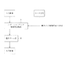
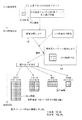
図2に示すように、パターンマッチング解像度変換部1は、ファクシミリ受信された入力画像の画像データ(2値)と、入力画像の解像度を示すモード信号とが入力されると、入力された画像データに対して、その解像度に応じたパターンマッチング解像度変換処理を施して出力画像の画像データ(2値)を生成して出力するものである。出力画像の画像データは、その後、電子ズーム部2を経て出力される。
【0027】
ファクシミリ装置に受信される入力画像の解像度は複数種類に及び、これら複数種類の解像の画像が、上記パターンマッチング解像度変換部1に入力されることとなる。ここでは、各入力解像度を、主走査方向×副走査方向に、m(i)×n(i)(i=,1,2,…:iは入力解像度の種類を表す)として表す。例えば4種類の入力解像度がある場合、i=1,2,3,4となる。
【0028】
このような複数の入力解像度における各主走査方向の解像度m(1),m(2),…は、その中の最小値の整数倍をなす関係にあり、同様に、各副走査方向の解像度n(1),n(2),…も、その中の最小値の整数倍をなす関係にある。したがって、m(i)及びn(i)それぞれの最小公倍数の解像度m(0), n(0)を求め、これを最大入力解像度m(0)×n(0)とし、この最大入力解像度の画素を基準画素とすることで、他の入力解像度の画素を、この基準画素を主走査方向×副走査方向に、m(0)/m(i)×n(0)/m(i)個並べたものとして扱うことが可能となる。
【0029】
図3(a)〜(e)に、入力解像度m(1)×n(1)=406.4dpi×391.2dpi、m(2)×n(2)=203.2dpi×391.2dpi、m(3)×n(3)=203.2dpi×195.6dpi、m(4)×n(4)=203.2dpi×97.8dpiとしたときのそれぞれの画素の大きさと、最大入力解像度m(0)×n(0)=406.4dpi×391.2dpiの画素(基準画素)の大きさを比較して示す。なお、上記入力解像度値は、ファクシミリ受信において一般に用いられる値であり、本ファクシミリ装置に入力される画像の解像度でもある。
【0030】
同図(a)に示すように、最大入力解像度m(0)×n(0)の画素である基準画素D1 の大きさは、主走査方向×副走査方向に、1/m(0)×1/n(0)で、各入力解像度の各画素の中で最小となる。同図(b)に示す入力解像度m(1)×n(1)は、m(1)=m(0),n(1)=n(0)の関係にあるため、その画素の大きさ(1/m(1)×1/n(1))は、同図(a)の基準画素D1 に同じになる。同図(c)に示す入力解像度m(2)×n(2)は、m(2)=m(0)×1/2,n(2)=n(0)の関係にあるため、その画素の大きさ(1/m(2)×1/n(2))は、基準画素D1 を主走査方向に2つ並べた大きさとなる。また、同図(d)に示す入力解像度m(3)×n(3)は、m(3)=m(0)×1/2,n(3)=n(0)×1/3の関係にあるため、その画素の大きさ(1/m(3)×1/n(3))は、基準画素D1 を主走査方向及び副走査方向に2×3個並べた大きさとなる。また、同図(e)に示す入力解像度m(4)×n(4)は、m(4)=m(0)×1/2,n(4)=n(0)×1/4の関係にあるため、その画素の大きさ(1/m(4)×1/n(4))は、基準画素D1 を主走査方向及び副走査方向に2×4個並べた大きさとなる。
【0031】
図3より明らかなように、入力解像度が複数ある場合、各解像度毎にそれぞれ画素の大きさは異なるが、最小公倍数の組み合わせからなる最大入力解像度m(0)×n(0)を考えることで、最大入力解像度の基準画素D1 を、主走査方向×副走査方向に、m(0)/m(i)×n(0)/m(i)個並べて、あたかも1種類の入力解像度として扱うことができる。
【0032】
一方、パターンマッチング解像度変換部1から出力される画像の解像度(以下出力解像度)は、後段に備えられたファクシミリ装置の作像部の解像度に応じた、x×y(x>m(0),y>n(0))であり、この出力解像度x×yは、m(i)×n(i)で表されるどの入力解像度よりも大きい値である。出力解像度x×yの画素の大きさは、1/x×1/yとなる。以下、この出力解像度の画素を出力側の基準画素D2 とする。
【0033】
ここで、最大入力解像度と出力解像度とを基に、p/x≒a/m(0),q/y≒b/n(0)を満足する、すなわち、図4に示すように、入力側の基準画素D1 がa×b(主走査方向×副走査方向)個並んだa×b画素ブロックと、出力側の基準画素D2 がp×q(主走査方向×副走査方向)個並んだp×q画素ブロックとがほぼ同じ大きさとなるようなa,b,p,qを求める。a,b,p,qは、いずれも自然数であり、aとp、bとqとは互いに素の関係を有する。
【0034】
上記の式において≒としたのは、m(0),n(0),x,yが必ずしも整数ではないためであって、これを=としたとき、a,b,p,qが非常に大きな値になって非実用的になることがあるためである。したがって、a,b,p,qとしては、できるだけ小さな整数の組を選べるように、近似することが望ましい。
【0035】
図4よりわかるように、入力側の基準画素D1 をa×b個並べてたa×b画素ブロックは、出力側の基準画素D2 をp×q個並べたp×q画素ブロックによって置き換えることができる。このことは、つまり同様にして、各入力解像度m(i)×n(i)の画素(入力側の基準画素D1 をm(0)/m(i)×n(0)/m(i)個並べてなる)をa×b個並べたa×b画素ブロックは、出力側の基準画素D2 をp×q個並べたp×q画素ブロックをm(0)/m(i)×n(0)/m(i)個並べた画素ブロックと同じ大きさになるので、これと置き換え可能と言うことである。
【0036】
したがって、入力画像の画像データに対しては、入力解像度の情報に関わらず、a×b画素ブロックを注目画素ブロックとし、この注目画素ブロックとその周辺の所定画素の情報とに対応するスムージング結果の置換用の画像パターンとして、出力側の基準画素D2 をp×q個並べたp×q画素ブロックの各画像パターンをLUT化して1種類備えさせると共に、別に入力解像度の違いによるこの置換用の画像パターンの配置情報を記憶させておくことで、注目画素を該LUTから読み出した置換用の画像パターン群(1つの場合もある)で置き換えることによりパターンマッチングを行うことができる。
【0037】
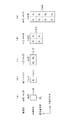
図1に、このようなパターンマッチングの手法を採用した、パターンマッチング解像度変換部1の構成を示す。パターンマッチング解像度変換部1は、入力画像分類部11、画像分類LUT12、出力パターン生成部13、および置換基本パターン格納LUT(置換パターン格納手段)14を備えている。
【0038】
入力画像分類部11は、画像メモリ(不図示)に格納されている入力画像の画像データ群より、注目画素とその周辺の画素とを抽出し、注目画素とその周辺画素の情報を基に、画像分類LUT12を参照して、注目画素の周辺画素との画像パターンの情報として、後述する入力基本パターンで表してなるテーブル番号を1つ選択し、出力パターン生成部13に出力する。
【0039】
ここで、上記入力画素分類部11は、各入力解像度と出力解像度とで前述したように決定される、a×b(主走査方向×副走査方向)画素ブロックを注目画素(注目画素ブロック)として扱う。
【0040】
本実施の形態のファクシミリ装置では、前述したように、入力解像度m(i)×n(i)として、406.4×391.2dpi(高精細)、203.2×391.2dpi(精細)、203.2×195.6dpi(小さい字)、203.2×97.8dpi(普通字)の4種類がある。また、作像部の解像度である出力解像度x×yは、600×600dpiである。最大入力解像度406.4×391.2dpiとして、前述のa,b,p,qを考えると、a=b=2、p=q=3となる。したがって、入力画像分類部11は、2×2画素ブロックを注目画素として扱う。
【0041】
入力画像分類部11に入力される注目画素としての2×2画素ブロックとその周辺画素との白黒情報(2値情報)は、注目画素を構成する画素数と、周辺画素として扱う周辺画素数によって決まるN種類の画像パターンで表される。そして、これらN種類の画像パターンは、例えば、全画素(注目画素及び周辺画素全て)黒のパターンが全画素白のパターンの反転であるように、垂直方向の鏡像、水平方向の鏡像、濃度の反転、及び回転(90°反時計回り)の各操作の組み合わせを用いることで、N種類より少ないM種類の基本パターン(以下、置換基本パターンとの差別化を明確にするために、入力基本パターンと称する)の使い回しで全て表現することができる。
【0042】
すなわち、上記画像分類LUT12には、これらN種類の入力画像の画像パターンの情報が個々にテーブル番号(N種類)を付して、入力基本パターンの番号を表す入力基本パターン情報に、垂直方向の鏡像(有無)、水平方向の鏡像(有無)、濃度の反転(有無)、及び回転(有無)の各操作情報が組み合わされて表現されており、入力画像分類部11は、この画像分類LUT12を参照して、注目画素ブロックの画像パターン情報として、テーブル番号を1つ選択して出力パターン生成部13に出力する。なお、上記入力画像分類部11及び画像分類LUT12により、本発明における入力画像解析手段が構成されている。
【0043】
出力パターン生成部13には、入力画像分類部11より入力されるテーブル番号と、入力解像度の情報とで、置換基本パターン格納LUT14より読み出すべき置換の画像パターン(置換パターン)のテーブル番号、及びその配置が決定されるテーブルが備えられている。
【0044】
置換基本パターン格納部14には、600×600dpiの3×3画素ブロックを1単位とした画像パターンが、前述の画像分類LUT12と同様に、29 =512通りの画像パターンの個々にテーブル番号(512種類)を付して、基本となる51種類の置換基本パターンの番号を表す情報に、垂直方向の鏡像(有無)、水平方向の鏡像(有無)、濃度の反転(有無)、及び回転(有無)の各操作情報が組み合わされて表現されている。
【0045】
出力パターン生成部13は、入力画像分類部11よりテーブル番号が入力されると、そのテーブル番号と、図2におけるモード信号として入力された入力解像度の情報とで、各入力解像度に応じて必要な置換用の画像パターンの情報をそのテーブル番号として置換基本パターン格納LUT14から必要数読み出し、解像度別にこのテーブル番号で表される画像パターンを、所定のアルゴリズムで組み合わせて並べて出力する。
【0046】
その後、パターンマッチング解像度変換部1より出力された画像は、電子ズーム処理され、a,b,c,dを求めるにあたって近似を行ったことによる画像の歪みが電子ズーム処理ブロック2にて補正される。電子ズーム処理の詳細については、具体的数値を挙げて、後述する。なお、近似を行うことなくa,b,c,dが求まる場合は、当然として電子ズーム処理の必要はない。このような場合としては、インチ系マシン同士で画像を送受信する構成がある。
【0047】
図1のパターンマッチング解像度変換部1のパターンマッチング解像度変換処理の手順を、図5を参照しながら説明する。
【0048】
まず、入力画像分類部11が、入力画像の画像データが格納されている画像メモリを参照して入力画像解析を行い、2×2画素ブロックの注目画素とその周辺の所定画素の情報とを得る(入力画像解析)。
【0049】
次に、入力画像分類部11は、上記2×2画素ブロックの注目画素およびその周辺情報とを基に、画像分類LUT12を参照して、入力画像のパターンに応じたテーブル番号を選択する。このテーブル番号の情報は、入力解像度の情報と共に、出力パターン生成部13に送られる。
【0050】
出力パターン生成部13は、このテーブル番号を基に、置換基本パターン格納LUT14より、入力基本パターンの種類に対応する解像度600dpi×600dpiの3×3画素ブロックの置換基本パターンを必要なだけ読み出し、入力画像の解像度ごとに読み出した置換基本パターンの組み合わせのアルゴリズムを実行する(出力画像作成)。
【0051】
例えば、最大入力解像度に等しい、高精細の入力解像度406.4dpi×391.2dpiの画像データでは、注目画素である2×2画素ブロックに対して、基本となる所定の3×3画素ブロックの置換基本パターンが1個割り当てられて置き換えられる。精細の入力解像度203.2dpi×391.2dpiの画像データでは、注目画素である2×2画素ブロックに対して、図5に示す如く所定の3×3画素ブロックの置換基本パターン2個が割り当てられて置き換えられる。
【0052】
小さい字の入力解像度203.2dpi×195.6dpiの画像データでは、注目画素である2×2画素ブロックに対して、図5に示す如く所定の3×3画素ブロックの置換基本パターン4個が、普通字の入力解像度203.2dpi×97.8dpiの画像データでは、注目画素である2×2画素ブロックに対して、図5に示す如く所定の3×3画素ブロックの置換基本パターン8個が割り当てられて置き換えられる(出力画像作成)。
【0053】
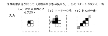
図6及び図7に、注目画素状態が同じで周辺画素状態が異なる場合に、出力パターンが変化する例を示す。図6(a)に示すように、注目画素の周辺に点がない場合、各解像度毎の出力パターンは、図7(a)に示すようなものとなる。また、図6(b)に示すように、注目画素がコーナーの端になるような場合は、各解像度毎の出力パターンは、図7(b)に示すようなものとなる。また、図6(c)に示すように、注目画素が斜線の途中の場合は、各解像度毎の出力パターンは、図7(c)に示すようなものとなる。
【0054】
その後、画像データはパターンマッチング解像度変換部1より出力され、図2に示した電子ズーム部2において、以下のように電子ズーム処理を施される。
【0055】
本実施の形態のファクシミリ装置では、p/x≒a/m(0),q/y≒b/n(0)となるa,b,p,qを決める際に、最大解像度m(0)×n(0)を、実際の値が406.4dpi×391.2dpiであるのを400dpi×400dpiと近似している。したがって、パターンマッチング解像度変換部1より出力される全ての出力画像は、入力画像に比べて主走査方向に若干伸び、副走査方向に若干縮んだ画像に変化している。そこで、この歪みを補正するために出力画像を、主走査方向に98.4(400dpi/406.4dpi)%、副走査方向に102.2(400dpi/391.2dpi)%変倍する電子ズームを行う。
【0056】
このときに実施される電子ズームは、100%近傍の微調であるため、従来、解像度に応じて150%や300%など画質がが大きく変動し兼ねない倍率を使用していたことと、広いズーム使用域のために画質管理上大きな手間がかかっていたこととを考え合わせると、画質の劣化を防ぐ上で大変有用である。
【0057】
以上のように、本実施の形態のファクシミリ装置に備えられたパターンマッチング解像度変換部1では、入力から入力画像の分類までは全解像度に共通の処理であり、分類から出力までが解像度別の処理となる。
【0058】
したがって、複数の入力解像度の画像に解像度変換と共にパターンマッチングでスムージング処理を施すことが、入力解像度の種類に関わらず、かつ、入力から入力画像の分類までの処理を各解像度共通に行いながら実施でき、また、入力画像に対して前段処理を要することもない。
【0059】
【発明の効果】
本発明の画像処置装置は、以上のように、入力画像に対して、主走査方向×副走査方向に画素がa×b個並んでなる画素ブロックを注目画素ブロックとし、この注目画素ブロックとその周辺の画素の情報とを基に、注目画素周辺の画像パターンを解析する入力画像解析手段と、出力側の解像度に応じた画素が主走査方向×副走査方向にp×q個並んでなる画素ブロックの各画像パターンが格納されている置換パターン格納手段と、上記入力画像解析手段にて解析された注目画素周辺の画像パターンと、入力画像の解像度とを基に、上記置換パターン格納手段を参照して所定の置換パターンを所定数読み出し、注目画素ブロックを読み出した各置換パターンを組み合わせてなる画像パターンで置き換えて出力する出力画像生成手段とを備え、上記a,b,p,qは、aとp、bとqとがそれぞれ互いに素となる自然数であり、全入力解像度の主走査方向値及び副走査方向値の各最小公倍数からなる最大解像度をm×n、出力側の解像度をx×yとすると、p/x≒a/m,q/y≒b/nを満足する値である構成である。
【0060】
これによれば、入力画像を画像解析してその画像パターンを分類するまでは、入力解像度に係わらず共通の処理で行い、その後の処理は、出力解像度の画素をp×q個並んた画素ブロックを基準とする置換パターン群格納手段から、解析結果の画像パターンと入力解像度とに応じた種類と数読み出して組み合わせ操作することで行うので、複数の入力解像度各々に、置換パターン格納手段を用意するようなことなく、解像度変換処理を行える。
【0061】
その結果、解像度が複数種類に及ぶ入力画像を出力解像度に合わせて解像度変換して出力する際に同時に、パターンマッチングでスムージングを施すことが、入力解像度の種類に関わらず、かつ、各解像度間で処理を共通化しながら、実施できるという効果を奏する。
【0062】
また、上記した本発明の画像処理装置においては、置換パターンへの置き換えを行った画像に対して、主走査方向及び副走査方向の長さの比が入力画像の同じになるようにズーム処理を施すズーム処理手段を備える構成とすることもできる。
【0063】
これによれば、置換パターンへの置き換えを行った画像に対して、主走査方向及び副走査方向の長さの比が入力時と同じになるようにズーム処理を施して、このような画像の歪みを補正できるので、入力画像を忠実に再現することが可能となるという効果を併せて奏する。
【0064】
特に、本発明の画像処理装置では、入力解像度の違いに係わらず、全て、解像度x×yのp×q画素ブロックを単位として置き換えを行っているので、入力時の比からのずれは各入力解像度とも同一となる。従って、ズーム処理の倍率は各解像度に共通のものとなり、後の処理段を大幅に簡略化することができる。
【0065】
さらに、上記した本発明の画像処置装置において、上記したx=y=600dpi、a=b=2、p=q=3とすることにより、ファクシミリ装置において汎用的な入力解像度203.2dpi×97.8dpi、203.2dpi×195.6dpi、203.2dpi×391.2dpi、406.4dpi×391.2dpiのいずれの画像を受信した場合にも、上記した効果を得ることができる。
【図面の簡単な説明】
【図1】本発明の実施の一形態を示すもので、パターンマッチング解像度変換部の詳細な構成を示すブロック図である。
【図2】上記パターンマッチング解像度変換部及び電子ズーム部を示すブロック図である。
【図3】(a)〜(e)は共に、入力画像の解像度毎の画素の形状を示す説明図である。
【図4】入力側基準画素をa×b個並べたa×b画素ブロックと、出力側基準画素をp×q個並べたp×q画素ブロックとの置き換えが可能であることを示す説明図である。
【図5】上記パターンマッチング解像度変換部において実施されるパターンマッチング解像度変換処理を示す説明図である。
【図6】図6(a)〜図6(c)は共に、注目画素状態が同じで周辺画素状態が異なる状態を示す説明図である。
【図7】図7(a)は、図6(a)に示す注目画素と周辺画素の状態の場合の、解像度毎の出力パターンを示すもので、図7(b)は、図6(b)に示す注目画素と周辺画素の状態の場合の、解像度毎の出力パターンを示すもので、図7(c)は、図6(c)の注目画素と周辺画素の状態の場合の、解像度毎の出力パターンを示すものである。
【符号の説明】
1 パターンマッチング解像度変換部
11 入力画像分類部(入力画像解析手段)
12 画像分類LUT(入力画像解析手段)
13 出力パターン生成部(出力画像生成手段)
14 置換基本パターン格納LUT(置換パターン格納手段)[0001]
TECHNICAL FIELD OF THE INVENTION
The present invention relates to an image processing apparatus mounted on an image forming apparatus such as a facsimile apparatus and a printer apparatus, and more particularly, to image processing for converting an input image having a plurality of resolutions into a resolution according to an output side resolution and outputting the converted image. It concerns the device.
[0002]
[Prior art]
Conventionally, in an image processing apparatus mounted on a facsimile apparatus, a printer apparatus, or the like, when performing scaling and resolution conversion on image data of an input image, there are various methods of performing smoothing to reduce jagged feeling of a hatched portion. Proposed.
[0003]
For example, Japanese Patent Application Laid-Open No. Sho 63-172664 discloses that when an input character pattern is enlarged twice vertically and horizontally and the resolution for the same character is doubled, a pixel of interest of an original image (input image) is included. A method is disclosed in which a predetermined interpolation operation is performed based on information of a 3 × 3 (main scanning direction × sub-scanning direction) pixel block, and the converted 6 × 6 pixel block is smoothed.
[0004]
Japanese Patent Application Laid-Open No. Hei 4-16060 discloses that when the pixel density of a binary image is enlarged and converted, the average density of the pixel of interest is calculated, the result is subjected to smoothing processing, and then binarized. A method is disclosed in which a high-quality image is obtained by outputting the image to reduce the jaggedness of oblique lines.
[0005]
[Problems to be solved by the invention]
However, according to the method of the above-mentioned conventional publication, when the resolution of an input image changes, it is necessary to perform arithmetic processing separately prepared for each resolution. And the processing becomes complicated depending on the resolution of the input image.
[0006]
In other words, taking a facsimile machine as an example, the resolution of an input image transmitted via a telephone line includes a main scanning direction x a sub-scanning direction.
(1) 203.2 dpi x 97.8 dpi
(2) 203.2 dpi x 195.6 dpi
(3) 203.2 dpi x 391.2 dpi
(4) 406.4 dpi x 391.2 dpi
and so on.
[0007]
Here, assuming that the resolution of the image forming unit (output side) of the facsimile apparatus is 600 dpi × 600 dpi in the main scanning direction × sub-scanning direction, the image processing apparatus mounted on the facsimile apparatus has a resolution of (1). The image data is converted into 203.2 dpi × 195.6 dpi by performing double interpolation in the sub-scanning direction, and then subjected to 3 × 3 times interpolation to obtain approximately 600 dpi × 600 dpi. For the image data of (3), 3 × 3 interpolation is performed to make it approximately 600 dpi × 600 dpi. For the image data of the above (3) resolution, 3 × (3/2) times interpolation is performed for For example, 600 dpi × 600 dpi, or (3/2) × (3/2) times interpolation for image data having the resolution of (4) to be approximately 600 dpi × 600 dpi. As described above, different arithmetic processing is performed for each resolution.
[0008]
Therefore, in order to smooth an image by pattern matching in each of the arithmetic processes, the image data having the resolution of (1) is subjected to double interpolation in the sub-scanning direction and then to the above (2). Although the operation is the same as that of the image data having the resolution of ▼, it is necessary to perform double interpolation in the sub-scanning direction in the preceding stage. Further, since the image data of the resolutions (3) and (4) are not integral multiples, the processing becomes complicated, and it is impossible at present to perform smoothing by pattern matching.
[0009]
The present invention has been made in view of the above problems, and an object of the present invention is to convert an input image having a plurality of types of resolution into an image of each input resolution when converting the input image to a resolution on the output side and outputting the converted image. An object of the present invention is to provide an image processing apparatus capable of performing smoothing interpolation on the other hand, and performing the operation as common as possible.
[0010]
[Means for Solving the Problems]
An image processing apparatus according to the present invention is an image processing apparatus that converts an input image to a resolution higher than that of an input side and outputs the converted image. The image processing apparatus in which the relationship between the values in the main scanning direction and the values in the sub-scanning direction in the resolution of each input image is an integral multiple of the minimum value has the following features.
[0011]
That is, a pixel block in which a × b pixels are arranged in the main scanning direction × sub-scanning direction in the input image is extracted as a pixel block of interest, and a pixel block of interest is extracted based on information of this pixel block of interest and surrounding pixels. Input image analysis means for analyzing an image pattern around a block, and a replacement pattern storage in which each image pattern of a pixel block in which pixels of resolution on the output side are arranged p × q in the main scanning direction × the sub-scanning direction is stored. Means, based on the image pattern around the target pixel analyzed by the input image analysis means, and the resolution of the input image, read a predetermined number of replacement patterns by referring to the replacement pattern storage means and combine them, Output image generating means for replacing and outputting the pixel block of interest with the combined image pattern, wherein a, b, p, and q are a and p, b and q Are the natural numbers that are relatively prime to each other. If the maximum resolution consisting of the least common multiple of the main scanning direction value and the sub-scanning direction value of the total input resolution is m × n, and the resolution on the output side is x × y, p / x ≒ a / m, q / y ≒ b / n.
[0012]
When there are a plurality of types of resolutions of the input image, the pixels of each input resolution are defined as the pixels of the maximum resolution m × n, which are the least common multiple of the main scanning direction value and the sub-scanning direction value of the entire input resolution, in the main scanning direction × the sub-scanning direction. In the scanning direction, m / each main scanning direction value × n / each sub scanning direction value can be represented by arranging them. The size of the pixel with the maximum resolution m × n is 1 / m × 1 / n. On the other hand, the size of the pixel of the resolution x × y of the output image is 1 / x × 1 / y.
[0013]
Therefore, based on the maximum resolution m × n and the output resolution xy, a value satisfying p / x ≒ a / m, q / y ≒ b / n, that is, the pixel having the maximum resolution on the input side is a × The values a, b, p, and q are determined so that the b × a pixel block and the p × q pixel blocks having the output resolution of p × q pixels have substantially the same size. Here, the values a, b, p, and q are natural numbers where a and p and b and q are mutually prime.
[0014]
In the above equation, ≒ is used because m, n, x, and y are not necessarily integers. When this is set to =, a, b, p, and q become very large values, and This is because it may become practical.
[0015]
By obtaining such a, b, p, and q, the a × b pixel block in which a × b pixels of the maximum resolution m × n on the input side are arranged is represented by p × q pixels of the output resolution x × y. It can be replaced by the p × q pixel blocks arranged. This means that, similarly, an a × b pixel block in which a × b pixels of resolution m1 × n1 of another input image are arranged is a p × p pixel in which p × q pixels of output resolution xy are arranged. Since the size of the q pixel block is the same as that of the pixel block in which m / m1 × n / n1 are arranged, it can be replaced with this.
[0016]
In the image processing apparatus of the present invention, the input image analyzing means converts the input image into a pixel block in which a × b pixels are arranged in the main scanning direction × the sub-scanning direction regardless of the resolution. The image pattern around the target pixel block is analyzed based on the target pixel block and the information on the pixels around the target pixel block.
[0017]
Then, after that, the output image generation unit refers to the replacement pattern storage unit based on the image pattern around the target pixel block analyzed by the input image analysis unit and the resolution of the input image, and sets the output resolution to Assuming that a predetermined number of predetermined replacement patterns composed of p × q pixel blocks in which p × q corresponding pixels are arranged, that is, the input resolution is m1 × n1, a pixel block in which m / m1 × n / n1 are arranged By replacing, the resolution can be converted.
[0018]
As described above, in the above configuration, common processing is performed irrespective of the input resolution until the input image is image-analyzed and its image pattern is classified. In the subsequent processing, p × q pixels of the output resolution are arranged. This is performed by reading and combining the types and numbers corresponding to the image pattern of the analysis result and the input resolution from the replacement pattern group storage means based on the p × q pixel block.
[0019]
Therefore, it is possible to perform smoothing by pattern matching at the same time when converting and outputting an input image having a plurality of types of resolutions in accordance with the output resolution, regardless of the type of input resolution and processing between each resolution. Can be implemented while standardizing. In addition, there is no need for pre-processing for the input image.
[0020]
Further, in the above-described image processing apparatus of the present invention, the zoom processing is performed on the image output from the output image generating unit so that the ratio of the length in the main scanning direction and the length in the sub-scanning direction is the same as that of the input image. A configuration including a zoom processing unit to be applied may be employed.
[0021]
Since the approximation of p / xqa / m and q / y ≒ b / n is performed, if the pixel block of interest is replaced with an image pattern obtained by combining the replacement patterns except when the equality is satisfied, the main part of the image is obtained. The ratio of the length in the scanning direction and the length in the sub-scanning direction is slightly distorted from the ratio at the time of input.
[0022]
In the above configuration, the zoom processing unit performs zoom processing on the image output from the output image generation unit so that the ratio of the lengths in the main scanning direction and the sub-scanning direction is the same as that of the input image. Since the image distortion is corrected, it is possible to faithfully reproduce the main / sub ratio (or size) of the input image.
[0023]
In particular, in the image processing apparatus of the present invention, regardless of the difference in the input resolution, all the pixels are replaced by a p × q pixel block in which p × q pixels of the output resolution x × y are arranged. Since the deviation from the time ratio is the same for each input resolution, the magnification of the zoom processing is common for each input resolution, and the subsequent processing stages can be greatly simplified.
[0024]
Further, in the image processing apparatus of the present invention described above, by setting x = y = 600 dpi, a = b = 2, and p = q = 3, a general-purpose input resolution of 203.2 × 97. The above-described effect can be obtained when any image of 8 dpi, 203.2 × 195.6 dpi, 203.2 × 391.2 dpi, and 406.4 × 391.2 dpi is received.
[0025]
BEST MODE FOR CARRYING OUT THE INVENTION
One embodiment of the present invention will be described below with reference to FIGS. In the present embodiment, an example in which the image processing apparatus of the present invention is employed as a pattern matching resolution conversion unit of a facsimile apparatus as an image forming apparatus will be described.
[0026]
As shown in FIG. 2, when the image data (binary) of the input image received by facsimile and the mode signal indicating the resolution of the input image are input, the pattern matching
[0027]
The resolution of the input image received by the facsimile apparatus is of a plurality of types, and the images of the plurality of types of resolution are input to the pattern matching
[0028]
The resolutions m (1), m (2),... In each main scanning direction at such a plurality of input resolutions have a relationship of forming an integral multiple of the minimum value among them. n (1), n (2),... also have a relationship of forming an integral multiple of the minimum value among them. Therefore, the resolutions m (0) and n (0) of the least common multiple of each of m (i) and n (i) are obtained, and these are defined as the maximum input resolution m (0) × n (0). By setting a pixel as a reference pixel, m (0) / m (i) × n (0) / m (i) pixels of other input resolutions are set in the main scanning direction × sub-scanning direction. It will be possible to treat them as being arranged.
[0029]
FIGS. 3A to 3E show input resolutions m (1) × n (1) = 406.4 dpi × 391.2 dpi, m (2) × n (2) = 203.2 dpi × 391.2 dpi, m (3) × n (3) = 203.2 dpi × 195.6 dpi, m (4) × n (4) = 203.2 dpi × 97.8 dpi, the size of each pixel and the maximum input resolution m ( 0) × n (0) = 406.4 dpi × 391.2 dpi The size of a pixel (reference pixel) is shown by comparison. The input resolution value is a value generally used in facsimile reception, and is also a resolution of an image input to the facsimile apparatus.
[0030]
As shown in FIG. 3A, a reference pixel D which is a pixel having a maximum input resolution m (0) × n (0) is used. 1 Is 1 / m (0) × 1 / n (0) in the main scanning direction × sub-scanning direction, and is the smallest among the pixels of each input resolution. Since the input resolution m (1) × n (1) shown in FIG. 3B has a relationship of m (1) = m (0) and n (1) = n (0), the size of the pixel is (1 / m (1) × 1 / n (1)) is the reference pixel D in FIG. 1 Will be the same. The input resolution m (2) × n (2) shown in FIG. 9C has a relationship of m (2) = m (0) × 1/2 and n (2) = n (0). The pixel size (1 / m (2) × 1 / n (2)) is equal to the reference pixel D 1 Are arranged in the main scanning direction. Also, the input resolution m (3) × n (3) shown in FIG. 4D is obtained by the following equation: m (3) = m (0) × 1/2, n (3) = n (0) × 1/3 Therefore, the size of the pixel (1 / m (3) × 1 / n (3)) is equal to the reference pixel D 1 Are arranged 2 × 3 in the main scanning direction and the sub-scanning direction. Further, the input resolution m (4) × n (4) shown in FIG. 11E is obtained by the following equation: m (4) = m (0) × 1 /, n (4) = n (0) × 1 / Therefore, the size of the pixel (1 / m (4) × 1 / n (4)) is equal to the reference pixel D 1 Are arranged 2 × 4 in the main scanning direction and the sub-scanning direction.
[0031]
As is clear from FIG. 3, when there are a plurality of input resolutions, the pixel size differs for each resolution, but by considering the maximum input resolution m (0) × n (0) which is a combination of the least common multiple. , The reference pixel D of the maximum input resolution 1 Are arranged m (0) / m (i) × n (0) / m (i) in the main scanning direction × sub-scanning direction, and can be treated as if they were one type of input resolution.
[0032]
On the other hand, the resolution of an image output from the pattern matching resolution conversion unit 1 (hereinafter referred to as output resolution) is x × y (x> m (0), x × y (x> m (0), depending on the resolution of the image forming unit of the facsimile machine provided at the subsequent stage). y> n (0)), and the output resolution x × y is a value larger than any input resolution represented by m (i) × n (i). The pixel size of the output resolution x × y is 1 / x × 1 / y. Hereinafter, a pixel having this output resolution is referred to as a reference pixel D on the output side. Two And
[0033]
Here, p / x ≒ a / m (0) and q / y ≒ b / n (0) are satisfied based on the maximum input resolution and the output resolution. That is, as shown in FIG. Reference pixel D 1 Are a × b (main scanning direction × sub-scanning direction) a × b pixel blocks and an output-side reference pixel D Two A, b, p, and q are determined so that p × q (main scanning direction × sub-scanning direction) p × q pixel blocks are substantially the same size. a, b, p, and q are all natural numbers, and a and p and b and q have a relatively prime relationship.
[0034]
In the above equation, ≒ is used because m (0), n (0), x, and y are not necessarily integers. When this is set to =, a, b, p, and q become very large. This is because a large value may be impractical. Therefore, it is desirable to approximate a, b, p, and q so that a set of integers as small as possible can be selected.
[0035]
As can be seen from FIG. 4, the reference pixel D on the input side 1 A × b pixel block in which a × b pixels are arranged is a reference pixel D on the output side. Two Can be replaced by a p × q pixel block in which p × q pixels are arranged. This means that the pixels of each input resolution m (i) × n (i) (the reference pixel D on the input side) 1 A × b pixel block in which a × b pixels are arranged in m (0) / m (i) × n (0) / m (i) is a reference pixel D on the output side. Two Is the same size as a pixel block in which p × q pixel blocks in which p × q pixels are arranged are arranged in m (0) / m (i) × n (0) / m (i). That is to say.
[0036]
Therefore, for the image data of the input image, regardless of the information of the input resolution, the a × b pixel block is set as the target pixel block, and the smoothing result corresponding to the target pixel block and the information of the predetermined pixels around the target pixel block is obtained. The reference pixel D on the output side is used as a replacement image pattern. Two By storing each type of image pattern of a p × q pixel block in which p × q pixel blocks are arranged as a LUT and separately storing arrangement information of the replacement image pattern due to a difference in input resolution, Pattern matching can be performed by replacing pixels with a replacement image pattern group (in some cases) read from the LUT.
[0037]
FIG. 1 shows a configuration of a pattern matching
[0038]
The input image classification unit 11 extracts a pixel of interest and its surrounding pixels from an image data group of the input image stored in an image memory (not shown), and, based on information of the pixel of interest and its surrounding pixels, With reference to the
[0039]
Here, the input pixel classification unit 11 sets an a × b (main scanning direction × sub-scanning direction) pixel block determined as described above with each input resolution and output resolution as a target pixel (target pixel block). deal with.
[0040]
In the facsimile apparatus of the present embodiment, as described above, the input resolution m (i) × n (i) is 406.4 × 391.2 dpi (high definition), 203.2 × 391.2 dpi (fine), There are four types: 203.2 × 195.6 dpi (small characters) and 203.2 × 97.8 dpi (normal characters). The output resolution x × y, which is the resolution of the image forming unit, is 600 × 600 dpi. Assuming a, b, p, and q as the maximum input resolution of 406.4 × 391.2 dpi, a = b = 2 and p = q = 3. Therefore, the input image classification unit 11 treats the 2 × 2 pixel block as a target pixel.
[0041]
The black-and-white information (binary information) of the 2 × 2 pixel block as the target pixel and its peripheral pixels input to the input image classification unit 11 is determined by the number of pixels constituting the target pixel and the number of peripheral pixels handled as peripheral pixels. It is represented by N types of determined image patterns. Then, these N types of image patterns are, for example, mirror images in the vertical direction, mirror images in the horizontal direction, and densities of the density such that the black pattern of all pixels (all the target pixel and the peripheral pixels) is the inverse of the white pattern of all pixels. By using a combination of operations of inversion and rotation (90 ° counterclockwise), M basic patterns less than N types (hereinafter referred to as input basic patterns in order to clarify differentiation from replacement basic patterns) ) Can be all expressed.
[0042]
That is, in the
[0043]
The output
[0044]
In the replacement basic
[0045]
When the table number is input from the input image classifying unit 11, the output
[0046]
Thereafter, the image output from the pattern matching
[0047]
The procedure of the pattern matching resolution conversion process of the pattern
[0048]
First, the input image classifying unit 11 performs input image analysis with reference to an image memory in which image data of the input image is stored, and obtains information of a target pixel of a 2 × 2 pixel block and predetermined pixels around the target pixel. (Input image analysis).
[0049]
Next, the input image classification unit 11 refers to the
[0050]
Based on the table number, the output
[0051]
For example, in the case of high-definition image data having an input resolution of 406.4 dpi × 391.2 dpi equal to the maximum input resolution, a basic 3 × 3 pixel block is replaced with a 2 × 2 pixel block as a target pixel. One basic pattern is assigned and replaced. In the image data having a fine input resolution of 203.2 dpi × 391.2 dpi, two 2 × 2 pixel blocks, which are the target pixels, are assigned two replacement basic patterns of a predetermined 3 × 3 pixel block as shown in FIG. Is replaced.
[0052]
In the image data of an input resolution of 203.2 dpi × 195.6 dpi of a small character, as shown in FIG. 5, four replacement basic patterns of a predetermined 3 × 3 pixel block are provided for a 2 × 2 pixel block as a target pixel. In image data of an input resolution of 203.2 dpi × 97.8 dpi of ordinary characters, eight replacement basic patterns of a predetermined 3 × 3 pixel block are allocated to a 2 × 2 pixel block as a target pixel as shown in FIG. Is replaced (output image creation).
[0053]
FIGS. 6 and 7 show an example in which the output pattern changes when the target pixel state is the same and the peripheral pixel state is different. As shown in FIG. 6A, when there is no point around the pixel of interest, the output pattern for each resolution is as shown in FIG. 7A. In addition, as shown in FIG. 6B, when the target pixel is located at the edge of the corner, the output pattern for each resolution is as shown in FIG. 7B. In addition, as shown in FIG. 6C, when the target pixel is in the middle of the oblique line, the output pattern for each resolution is as shown in FIG. 7C.
[0054]
Thereafter, the image data is output from the pattern matching
[0055]
In the facsimile apparatus of the present embodiment, when determining a, b, p, and q such that p / x ≒ a / m (0) and q / y ≒ b / n (0), the maximum resolution m (0) The actual value of xn (0), which is 406.4 dpi × 391.2 dpi, is approximated to 400 dpi × 400 dpi. Therefore, all the output images output from the pattern
[0056]
Since the electronic zoom performed at this time is a fine adjustment in the vicinity of 100%, conventionally, a magnification such as 150% or 300% is used in accordance with the resolution so that the image quality does not greatly fluctuate. This is very useful in preventing the deterioration of the image quality in consideration of the fact that a great deal of time has been taken in image quality management for the use area.
[0057]
As described above, in the pattern matching
[0058]
Therefore, it is possible to perform smoothing processing by pattern matching together with resolution conversion on images of a plurality of input resolutions, regardless of the type of input resolution, and to perform processing from input to classification of input images while performing processing common to each resolution. Also, there is no need for pre-processing on the input image.
[0059]
【The invention's effect】
As described above, the image processing apparatus of the present invention sets a pixel block in which a × b pixels are arranged in the main scanning direction × sub-scanning direction with respect to an input image as a target pixel block, and An input image analyzing means for analyzing an image pattern around a target pixel based on information on peripheral pixels, and a pixel in which p × q pixels are arranged in the main scanning direction × sub-scanning direction in accordance with the resolution on the output side Refer to the replacement pattern storage means based on the replacement pattern storage means storing each image pattern of the block, the image pattern around the target pixel analyzed by the input image analysis means, and the resolution of the input image. Output image generating means for reading out a predetermined number of predetermined replacement patterns and replacing the read-out pixel block with an image pattern formed by combining the read-out replacement patterns, and , B, p, and q are natural numbers where a and p and b and q are mutually prime, and the maximum resolution consisting of the least common multiple of the main scanning direction value and the sub-scanning direction value of the entire input resolution is m × n, and the resolution on the output side is x × y, the configuration is a value that satisfies p / x ≒ a / m and q / y ≒ b / n.
[0060]
According to this, common processing is performed irrespective of the input resolution until the input image is subjected to image analysis and its image pattern is classified, and the subsequent processing is performed in a pixel block in which p × q pixels of the output resolution are arranged. The replacement pattern storage means is prepared for each of a plurality of input resolutions, by reading out the types and numbers corresponding to the image pattern of the analysis result and the input resolution and performing the combination operation from the replacement pattern group storage means based on Without this, the resolution conversion process can be performed.
[0061]
As a result, it is possible to perform smoothing by pattern matching at the same time as converting an input image having multiple types of resolutions according to the output resolution and outputting it, regardless of the type of input resolution and between each resolution. There is an effect that the processing can be performed while the processing is shared.
[0062]
In the above-described image processing apparatus of the present invention, the zoom process is performed on the image that has been replaced with the replacement pattern so that the ratio of the lengths in the main scanning direction and the sub-scanning direction is the same as that of the input image. It is also possible to adopt a configuration having a zoom processing means for applying.
[0063]
According to this, a zoom process is performed on an image that has been replaced with a replacement pattern so that the ratio of the lengths in the main scanning direction and the sub-scanning direction is the same as that at the time of input. Since the distortion can be corrected, the effect that the input image can be faithfully reproduced can be obtained.
[0064]
In particular, in the image processing apparatus of the present invention, regardless of the difference in the input resolution, all the pixels are replaced in units of p × q pixel blocks of resolution x × y. The resolution is the same. Therefore, the magnification of the zoom processing is common to each resolution, and the subsequent processing stages can be greatly simplified.
[0065]
Further, in the image processing apparatus of the present invention, by setting x = y = 600 dpi, a = b = 2, and p = q = 3, a general-purpose input resolution of 203.2 dpi × 97. The above-described effect can be obtained when any image of 8 dpi, 203.2 dpi × 195.6 dpi, 203.2 dpi × 391.2 dpi, and 406.4 dpi × 391.2 dpi is received.
[Brief description of the drawings]
FIG. 1 illustrates an embodiment of the present invention, and is a block diagram illustrating a detailed configuration of a pattern matching resolution conversion unit.
FIG. 2 is a block diagram showing a pattern matching resolution conversion unit and an electronic zoom unit.
FIGS. 3A to 3E are explanatory diagrams showing the shapes of pixels for each resolution of an input image.
FIG. 4 is an explanatory diagram showing that it is possible to replace an a × b pixel block in which a × b input-side reference pixels are arranged and a p × q pixel block in which p × q output-side reference pixels are arranged; It is.
FIG. 5 is an explanatory diagram showing a pattern matching resolution conversion process performed in the pattern matching resolution conversion unit.
FIGS. 6A to 6C are explanatory diagrams showing states in which the state of the target pixel is the same and the states of the peripheral pixels are different.
7A shows an output pattern for each resolution in the case of a target pixel and peripheral pixels shown in FIG. 6A, and FIG. 7B shows the output pattern of FIG. FIG. 7C shows an output pattern for each resolution in the state of the target pixel and the peripheral pixels shown in FIG. 7C. FIG. 7C shows the output pattern for each resolution in the state of the target pixel and the peripheral pixels in FIG. FIG.
[Explanation of symbols]
1 Pattern matching resolution converter
11 input image classification unit (input image analysis means)
12 Image classification LUT (input image analysis means)
13 Output pattern generation unit (output image generation means)
14. Replacement basic pattern storage LUT (replacement pattern storage means)
Claims (3)
入力画像における主走査方向×副走査方向に画素がa×b個並んでなる画素ブロックを注目画素ブロックとして抽出し、この注目画素ブロックとその周辺の画素の情報とを基に、注目画素ブロック周辺の画像パターンを解析する入力画像解析手段と、
出力側の解像度の画素が主走査方向×副走査方向にp×q個並んでなる画素ブロックの各画像パターンが格納されている置換パターン格納手段と、
上記入力画像解析手段にて解析された注目画素周辺の画像パターンと、入力画像の解像度とを基に、上記置換パターン格納手段を参照して所定の置換パターンを所定数読み出して組み合わせ、該組み合わせた画像パターンで上記注目画素ブロックを置き換えて出力する出力画像生成手段とを備え、
上記a,b,p,qは、aとp、bとqとがそれぞれ互いに素となる自然数であり、全入力解像度の主走査方向値及び副走査方向値の各最小公倍数からなる最大解像度をm×n、出力側の解像度をx×yとすると、p/x≒a/m,q/y≒b/nを満足する値であることを特徴とする画像処理装置。An image processing apparatus for converting an input image to a resolution on the output side larger than the input side and outputting the converted image, wherein there are a plurality of types of resolution of the input image, between the main scanning direction values in the resolution of each of these input images, and In an image processing apparatus in which the relationship between the sub-scanning direction values and the minimum value is an integer multiple,
A pixel block in which a × b pixels are arranged in the main scanning direction × sub-scanning direction in the input image is extracted as a pixel block of interest, and a pixel block of the pixel block of interest Input image analysis means for analyzing the image pattern of
Replacement pattern storage means for storing each image pattern of a pixel block in which pixels of the resolution on the output side are arranged in p × q pixels in the main scanning direction × sub-scanning direction;
Based on the image pattern around the target pixel analyzed by the input image analysis unit and the resolution of the input image, a predetermined number of predetermined replacement patterns are read out and combined with reference to the replacement pattern storage unit, and the combination is performed. Output image generating means for replacing and outputting the pixel block of interest with an image pattern,
A, b, p, and q are natural numbers in which a and p and b and q are mutually prime, and represent the maximum resolution consisting of the least common multiple of the main scanning direction value and the sub-scanning direction value of all input resolutions. An image processing apparatus characterized in that the value satisfies p / x ≒ a / m and q / y す る と b / n, where m × n and resolution on the output side is x × y.
Priority Applications (1)
| Application Number | Priority Date | Filing Date | Title |
|---|---|---|---|
| JP33201199A JP3539552B2 (en) | 1999-11-22 | 1999-11-22 | Image processing device |
Applications Claiming Priority (1)
| Application Number | Priority Date | Filing Date | Title |
|---|---|---|---|
| JP33201199A JP3539552B2 (en) | 1999-11-22 | 1999-11-22 | Image processing device |
Publications (2)
| Publication Number | Publication Date |
|---|---|
| JP2001157037A JP2001157037A (en) | 2001-06-08 |
| JP3539552B2 true JP3539552B2 (en) | 2004-07-07 |
Family
ID=18250153
Family Applications (1)
| Application Number | Title | Priority Date | Filing Date |
|---|---|---|---|
| JP33201199A Expired - Fee Related JP3539552B2 (en) | 1999-11-22 | 1999-11-22 | Image processing device |
Country Status (1)
| Country | Link |
|---|---|
| JP (1) | JP3539552B2 (en) |
Families Citing this family (4)
| Publication number | Priority date | Publication date | Assignee | Title |
|---|---|---|---|---|
| JP4510069B2 (en) * | 2007-12-10 | 2010-07-21 | シャープ株式会社 | Image processing apparatus, image display apparatus, image forming apparatus, image processing method, computer program, and storage medium |
| JP4956464B2 (en) * | 2008-02-28 | 2012-06-20 | 株式会社東芝 | Image high resolution device, learning device and method |
| JP5085589B2 (en) * | 2009-02-26 | 2012-11-28 | 株式会社東芝 | Image processing apparatus and method |
| JP5751038B2 (en) * | 2010-12-20 | 2015-07-22 | 株式会社リコー | Image forming apparatus, image forming method, and integrated circuit |
-
1999
- 1999-11-22 JP JP33201199A patent/JP3539552B2/en not_active Expired - Fee Related
Also Published As
| Publication number | Publication date |
|---|---|
| JP2001157037A (en) | 2001-06-08 |
Similar Documents
| Publication | Publication Date | Title |
|---|---|---|
| JPH03193472A (en) | Highly definite image generating system of image processor | |
| JPH07131634A (en) | Image processor | |
| US5862305A (en) | Logic filters for resolution conversion of digital images | |
| JP3539552B2 (en) | Image processing device | |
| JP3578878B2 (en) | Image processing device | |
| JPH08116440A (en) | Multilevel image binarizing device | |
| US6628427B1 (en) | Method and apparatus for image processing which improves performance of gray scale image transformation | |
| US20030020935A1 (en) | Image processing method and apparatus | |
| JP3478861B2 (en) | Smoothing enlargement processing method for binary image data | |
| JP3581460B2 (en) | Image processing method and apparatus | |
| JP3584329B2 (en) | Image forming device | |
| JP3783815B2 (en) | Image processing device | |
| JP3117331B2 (en) | Image data processing device | |
| JP3624153B2 (en) | Image processing apparatus and image processing method | |
| JPS60136478A (en) | Picture processor | |
| JPH07182503A (en) | Method and device for processing image | |
| JP3678319B2 (en) | Image density converter | |
| JP3949642B2 (en) | Image processing device | |
| JP3054315B2 (en) | Image processing method and apparatus | |
| JP2608404B2 (en) | Image processing device | |
| JP3221152B2 (en) | Facsimile machine | |
| JP3452202B2 (en) | Image processing method | |
| JPH0832798A (en) | Method and device for processing image | |
| JPH08147460A (en) | Image processing method | |
| JPH0638038A (en) | Smoothing processing method for binary image |
Legal Events
| Date | Code | Title | Description |
|---|---|---|---|
| A977 | Report on retrieval |
Free format text: JAPANESE INTERMEDIATE CODE: A971007 Effective date: 20040308 |
|
| TRDD | Decision of grant or rejection written | ||
| A01 | Written decision to grant a patent or to grant a registration (utility model) |
Free format text: JAPANESE INTERMEDIATE CODE: A01 Effective date: 20040316 |
|
| A61 | First payment of annual fees (during grant procedure) |
Free format text: JAPANESE INTERMEDIATE CODE: A61 Effective date: 20040317 |
|
| R150 | Certificate of patent or registration of utility model |
Free format text: JAPANESE INTERMEDIATE CODE: R150 |
|
| FPAY | Renewal fee payment (event date is renewal date of database) |
Free format text: PAYMENT UNTIL: 20080402 Year of fee payment: 4 |
|
| FPAY | Renewal fee payment (event date is renewal date of database) |
Free format text: PAYMENT UNTIL: 20090402 Year of fee payment: 5 |
|
| FPAY | Renewal fee payment (event date is renewal date of database) |
Free format text: PAYMENT UNTIL: 20100402 Year of fee payment: 6 |
|
| FPAY | Renewal fee payment (event date is renewal date of database) |
Free format text: PAYMENT UNTIL: 20100402 Year of fee payment: 6 |
|
| FPAY | Renewal fee payment (event date is renewal date of database) |
Free format text: PAYMENT UNTIL: 20110402 Year of fee payment: 7 |
|
| FPAY | Renewal fee payment (event date is renewal date of database) |
Free format text: PAYMENT UNTIL: 20120402 Year of fee payment: 8 |
|
| FPAY | Renewal fee payment (event date is renewal date of database) |
Free format text: PAYMENT UNTIL: 20120402 Year of fee payment: 8 |
|
| FPAY | Renewal fee payment (event date is renewal date of database) |
Free format text: PAYMENT UNTIL: 20130402 Year of fee payment: 9 |
|
| LAPS | Cancellation because of no payment of annual fees |