JP3212775U - Door installation mechanism for smart lock system - Google Patents
Door installation mechanism for smart lock system Download PDFInfo
- Publication number
- JP3212775U JP3212775U JP2016600142U JP2016600142U JP3212775U JP 3212775 U JP3212775 U JP 3212775U JP 2016600142 U JP2016600142 U JP 2016600142U JP 2016600142 U JP2016600142 U JP 2016600142U JP 3212775 U JP3212775 U JP 3212775U
- Authority
- JP
- Japan
- Prior art keywords
- coupling
- door
- installation mechanism
- sub
- door installation
- Prior art date
- Legal status (The legal status is an assumption and is not a legal conclusion. Google has not performed a legal analysis and makes no representation as to the accuracy of the status listed.)
- Ceased
Links
Images


Classifications
-
- E—FIXED CONSTRUCTIONS
- E05—LOCKS; KEYS; WINDOW OR DOOR FITTINGS; SAFES
- E05B—LOCKS; ACCESSORIES THEREFOR; HANDCUFFS
- E05B47/00—Operating or controlling locks or other fastening devices by electric or magnetic means
- E05B47/0001—Operating or controlling locks or other fastening devices by electric or magnetic means with electric actuators; Constructional features thereof
- E05B47/0012—Operating or controlling locks or other fastening devices by electric or magnetic means with electric actuators; Constructional features thereof with rotary electromotors
-
- E—FIXED CONSTRUCTIONS
- E05—LOCKS; KEYS; WINDOW OR DOOR FITTINGS; SAFES
- E05B—LOCKS; ACCESSORIES THEREFOR; HANDCUFFS
- E05B47/00—Operating or controlling locks or other fastening devices by electric or magnetic means
- E05B47/02—Movement of the bolt by electromagnetic means; Adaptation of locks, latches, or parts thereof, for movement of the bolt by electromagnetic means
-
- E—FIXED CONSTRUCTIONS
- E05—LOCKS; KEYS; WINDOW OR DOOR FITTINGS; SAFES
- E05B—LOCKS; ACCESSORIES THEREFOR; HANDCUFFS
- E05B47/00—Operating or controlling locks or other fastening devices by electric or magnetic means
- E05B2047/0084—Key or electric means; Emergency release
-
- E—FIXED CONSTRUCTIONS
- E05—LOCKS; KEYS; WINDOW OR DOOR FITTINGS; SAFES
- E05B—LOCKS; ACCESSORIES THEREFOR; HANDCUFFS
- E05B47/00—Operating or controlling locks or other fastening devices by electric or magnetic means
- E05B2047/0091—Retrofittable electric locks, e.g. an electric module can be attached to an existing manual lock
-
- E—FIXED CONSTRUCTIONS
- E05—LOCKS; KEYS; WINDOW OR DOOR FITTINGS; SAFES
- E05B—LOCKS; ACCESSORIES THEREFOR; HANDCUFFS
- E05B47/00—Operating or controlling locks or other fastening devices by electric or magnetic means
- E05B2047/0094—Mechanical aspects of remotely controlled locks
- E05B2047/0095—Mechanical aspects of locks controlled by telephone signals, e.g. by mobile phones
Landscapes
- Physics & Mathematics (AREA)
- Electromagnetism (AREA)
- Casings For Electric Apparatus (AREA)
- Lock And Its Accessories (AREA)
Abstract
【課題】スマートロックシステムのためのドア設置機構を提供する。【解決手段】ドア設置機構はドアに設置されてドアロックのサムターンを回すように構成され、ケーシング1と、回転部品2と、中間カップリングとを含む。ケーシング1は、ドアに当接するもので、ベース壁11と共に周壁12を具え、ドアロックを収容できるように構成された収容空間を画成している。回転部品2はケーシング1に回転可能に連結されている。中間カップリングは、回転部品2と共に回転可能に接続されている第1のカップリング部と、第1のカップリング部と共に回転可能に且つ第1のカップリング部に対して直線的に移動可能に接続されていて、サムターンが回転部品と共に回転可能になるようドアロックのサムターンの回転を駆動するように構成された第2のカップリング部とを含む。【選択図】図4A door installation mechanism for a smart lock system is provided. A door installation mechanism is configured to be installed on a door and rotate a thumb turn of a door lock, and includes a casing 1, a rotating component 2, and an intermediate coupling. The casing 1 comes into contact with the door, and includes a peripheral wall 12 together with the base wall 11, and defines an accommodation space configured to accommodate a door lock. The rotating component 2 is rotatably connected to the casing 1. The intermediate coupling is rotatable with the rotating component 2 and is rotatable with the first coupling unit and linearly movable with respect to the first coupling unit. And a second coupling portion connected and configured to drive rotation of the thumb turn of the door lock so that the thumb turn is rotatable with the rotating component. [Selection] Figure 4
Description
[関連する出願の相互参照]
本出願は、2014年10月8日に出願された米国特許仮出願第62/061212号、2014年10月8日に出願された米国特許仮出願第62/061204号、及び、2014年10月8日に出願された米国特許仮出願第62/061209号の優先権を主張するものである。
[Cross-reference of related applications]
This application includes US Provisional Application No. 62/062121, filed Oct. 8, 2014, US Provisional Application No. 62/0661204, filed Oct. 8, 2014, and October 2014. The priority of US Provisional Patent Application No. 62/061209 filed on the 8th is claimed.
本考案は、ドア設置機構に関し、より詳しくは、スマートロックシステムのためのドア設置機構に関する。 The present invention relates to a door installation mechanism, and more particularly to a door installation mechanism for a smart lock system.
電子セキュリティシステムはすでに長年に渡って知られている。ここ数年では、電子技術が旧来のドアロックと共に用いられたものとしてスマートロックがある。従来のスマートロックは、ドアロックに取り付けられるように構成されてコントロールシステムによって制御されるドア設置部を通常含む。このような従来のスマートロックの欠点として、ドア設置部の取り付けが比較的複雑で時間がかかるという点がある。 Electronic security systems have been known for many years. In recent years, smart locks have been one of the uses of electronic technology with traditional door locks. Conventional smart locks typically include a door installation configured to be attached to the door lock and controlled by a control system. A drawback of such a conventional smart lock is that the installation of the door installation portion is relatively complicated and time consuming.
図1は、典型的な機械式ロック装置100を示している。この機械式ロック装置100は、ベースプレート102と、ベースプレート102に回転可能に接続されたサムターン104とを含む。使用に当たって、機械式ロック装置100は、ベースプレート102がドア200のハンドル202に近い位置に連結されるようにしてドア200に設置される(図2参照)。機械式ロック装置100は、サムターン104の形状によって、例えば楕円形(図1参照)、三角形(図2参照)、円形(図3参照)といった様々な構成を有し、またベースプレート102におけるサムターン104の位置によっても構成が異なる。
FIG. 1 shows a typical
上記従来のスマートロックの他の欠点は、機械式ロック装置100のサムターン104のサイズや位置の違いによっては、従来のスマートロックのドア設置部をしっかりとすみやかに取り付けることができなくなるという点である。
Another drawback of the above-described conventional smart lock is that the door installation portion of the conventional smart lock cannot be securely and quickly attached depending on the size and position of the
従って、本考案の目的は、上記従来技術に関連する欠点を少なくとも1つ解決することができるスマートロックシステムのためのドア設置機構を提供することにある。 SUMMARY OF THE INVENTION Accordingly, an object of the present invention is to provide a door installation mechanism for a smart lock system that can solve at least one of the disadvantages associated with the prior art.
従って、本考案に係るドア設置機構は、スマートロックシステムに用いられるように構成されたものである。当該ドア設置機構は、ドアに設置されて前記ドアに設置されているドアロックのサムターンを回すように構成されている。当該ドア設置機構は、ケーシングと、回転部品と、中間カップリングとを含む。前記ケーシングは、前記ドアに当接するように構成されたドア設置端を有し、且つ、前記ドアロックを収容できるように構成されると共に前記ドア設置端に開口を有し前記ドアロックをその内に延伸させて通すように構成された収容空間を画成している。前記回転部品は、前記ケーシングに回転可能に連結されている。前記中間カップリングは、前記回転部品と共に回転可能に接続されている第1のカップリング部と、前記第1のカップリング部と共に回転可能に且つ前記第1のカップリング部に対して直線的に移動可能に接続されていて、前記サムターンが前記回転部品と共に回転可能になるよう前記ドアロックの前記サムターンの回転を駆動するように構成された第2のカップリング部とを含む。 Therefore, the door installation mechanism according to the present invention is configured to be used in a smart lock system. The said door installation mechanism is comprised so that the thumb turn of the door lock installed in the said door may be installed in the door. The door installation mechanism includes a casing, a rotating component, and an intermediate coupling. The casing has a door installation end configured to contact the door, and is configured to receive the door lock, and has an opening at the door installation end, and the door lock is disposed therein. The housing space is configured to extend and pass through. The rotating component is rotatably connected to the casing. The intermediate coupling includes a first coupling portion that is rotatably connected with the rotating component, and is rotatable with the first coupling portion and linearly with respect to the first coupling portion. And a second coupling portion movably connected and configured to drive rotation of the thumb turn of the door lock so that the thumb turn is rotatable with the rotating component.
本考案の他の特徴および利点は、添付の図面を参照する以下の実施形態の詳細な説明において明白になるであろう。 Other features and advantages of the present invention will become apparent in the following detailed description of embodiments with reference to the accompanying drawings.
本考案をより詳細に説明する前に、各実施形態において同様の要素には同じ符号が付されることに留意されたい。 Before describing the present invention in more detail, it should be noted that like elements are given like reference numerals in the respective embodiments.
図4〜図8に示されているように、本考案に係るドア設置機構の一実施形態は、スマートロックシステムに用いることができるように構成され、且つ、ドアロック(図示せず)のサムターン(図示せず)を回すことができるようにドア(図示せず)に設置されるように構成されたものである。上記ドアロックは、ドアに設置されサムターンが回転可能に配置されているベースプレート(図示せず)を具える。上記ドア設置機構は、ケーシング1と、回転部品2と、作動ユニット3と、中間カップリング4とを含む。
As shown in FIGS. 4 to 8, an embodiment of the door installation mechanism according to the present invention is configured to be used in a smart lock system, and a thumb turn of a door lock (not shown). (Not shown) is configured to be installed on a door (not shown) so that it can be turned. The door lock includes a base plate (not shown) that is installed on the door and on which a thumb turn is rotatably arranged. The door installation mechanism includes a
ケーシング1は、ベース壁11と、ベース壁11の周縁から延伸してベース壁11と共に収容空間100(図7参照)を画成する周壁12とを具える。本実施形態においてベース壁11はほぼ正方形である。周壁12はドア設置端121を有し、収容空間100はドア設置端121に開口101(図7参照)を有する。本実施形態において、ベース壁11には円形孔111が形成されている。
The
回転部品2は、ケーシング1に回転可能に連結されている。回転部品2は、ケーシング1の円形孔111に回転可能に嵌め入れられているベース部21と、ベース部21から収容空間100と離れる方向に突出していて使用者がつまむことができるノブ部22とを有する。
The
作動ユニット3は、モーターと電磁弁を有する作動モジュール31と、作動モジュール31のモーターにより回転駆動されるギアセット32とを具える。作動ユニット3は、制御回路(図示せず)に接続されている。スマートロックシステムの操作中に、制御回路がユーザーデバイス、例えば携帯電話からコマンドを受け取ると、作動ユニット3が制御回路から受け取った信号により起動されて回転部品2を回転駆動するように稼動する。
The operation unit 3 includes an
中間カップリング4は、第1のカップリング部41と第2のカップリング部42を含む。本実施形態において、第2のカップリング部42は、弾性材料で構成されていると共に、中空フレームとして形成されていて、2つの平行なサイドフレーム部分421と、それぞれサイドフレーム部分421に形成されていて互いに反対向きになっている2つの平行なスライド溝422(図8では1つだけが図示されている)とを有する。第1のカップリング部41は2つの副部411を有する。各副部411は伸縮可能な構造に構成されていて、回転部品2と共に回転可能に接続固定された第1の端と、第1の端の反対側にあって対応の1つのスライド溝422にスライド可能に係合する第2の端とを有する。より詳しく言うと、2つの副部411は互いに同一線上に位置決めされ、スライド溝422とは垂直になっている。これにより、各副部411の第1の端と第2の端の間の距離は調整可能となっていて、第2のカップリング部42は、第1のカップリング部41と回転可能に接続されると共に第1のカップリング部41に対して直線移動できるようになっている(図8及び図9参照)。
The
使用に当たってケーシング1はドアに取り付けられるが、その際には、周壁12のドア設置端121がドアに当接すると共にドアロックのベースプレートを囲むように、且つ、ドアロックのサムターンが第2のカップリング部42に囲まれるよう挿入されるまでドアロックが開口101を通って収容空間100に延伸するように取り付けられる。第2のカップリング部42とドアロックのサムターンとが相互接続されている間、サイドフレーム部分421の弾性と、第1のカップリング部41の副部411が伸縮可能な構造を有し長さ調節が可能であることにより、サイドフレーム部分421は副部411が延伸する方向である第1の方向に変形可能となる。更に、第2のカップリング部42は、第1のカップリング部41に対して、第1の方向と垂直である第2の方向でスライド可能となる。従って、中間カップリング4は、異なるサイズや形状のサムターンに取り付けられまたベースプレートの相対的な位置の変化に対応するという点で、比較的高い適応性を有する。これにより、作動ユニット3が回転部品2の回転を作動するように遠隔操作されると、サムターンが回転部品2と共に回される。また、ノブ部22が使用者によりつまむことができるので、回転部品2は手動によっても回すことができる。
In use, the
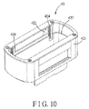
図10及び図11は、第1の実施形態の変化例を示しており、本例では、第2のカップリング部42は、伸縮可能にサイドフレーム部分421に連結された延伸部分423と、サイドフレーム部分421と延伸部分423の間に配置されると共に延伸部分423の角に位置して延伸部分423をサイドフレーム部分421から離れる方向に付勢する複数の弾性部材424とを更に有する。これにより、中間カップリング4(図7参照)は、サムターンが回転可能に設置されたベースプレートに対して延伸部分423の延伸端が弾性的に当接することにより、比較的大きいサムターンでもしっかりと保持することができる。
10 and 11 show a variation of the first embodiment. In this example, the
図12〜図14は、第1の実施形態の他の変化例が示されていて、本例では、延伸部分423には複数の位置決めスロット4231が形成されていて、また、サイドフレーム部分421には複数の位置決め突起4211(図13ではそのうちの1つだけが見えている)が形成されている。使用者は手動で延伸部分423をサイドフレーム部分421に対して動かし、位置決め突起4211をそれぞれ対応の位置決めスロット4231に係合させることで延伸部分423をサイドフレーム部分421に対する所望の位置に位置決めすることができる。
FIGS. 12 to 14 show other modified examples of the first embodiment. In this example, a plurality of
図15及び図16に示されているように、本考案に係るドア設置機構の第2の実施形態は、中間カップリング4の構成が第1の実施形態と異なる。
As shown in FIGS. 15 and 16, the second embodiment of the door installation mechanism according to the present invention differs from the first embodiment in the configuration of the
本実施形態において、中間カップリング4は、第1のカップリング部41と第2のカップリング部42との間に配置された第3のカップリング部43を更に含む。また、中間カップリング4はオルダムカップリングとして構成されている。より詳しく言うと、第1のカップリング部41は、細長い溝4102が形成されたプレート部分4101と、細長い溝の反対側4102で突起して回転部品2(図4参照)と共に回転可能に接続された係合部分4103とを有する。第3のカップリング部43は、第1のカップリング部41に面する表面と、上記表面に形成されていて細長い溝4102にスライド可能に嵌まるように係合する細長い舌状部4301とを有する。第2のカップリング部42及び第3のカップリング部43は同じさね継ぎ機構により互いに連結されているが、第2のカップリング部42及び第3のカップリング部43の間に設けられた細長い舌状部と溝は、第1のカップリング部42及び第3のカップリング部43の間に設けられた細長い舌状部と溝に対して垂直である。
In the present embodiment, the
なお、第2のカップリング部42は、複数の代替可能なカップリングヘッドとして構成されてもよい。図18及び図19に示されているように、各前記カップリングヘッドは、所定の形状を有し該所定形状と同じ形状のサムターンを納められるように構成されたキャビティ4202が形成されている本体4201を有する。例えば、ほぼ長方形のサムターンに対しては、このようなサムターンに合うように複数のカップリングヘッドのうちほぼ長方形に形成されたキャビティ4202を有する1つが選ばれる。
The
また、本実施形態では細長い溝4102はプレート部分4101にのみ形成されているが、他の実施形態において細長い溝4102はプレート部分4101を経て係合部分4103にまで形成されてもよく(図17参照)、これによりプレート部分4101の厚みを減らすことができ、中間カップリング4を小型化できるようになる。
In this embodiment, the
図20に示されているように、本考案に係るドア設置機構の第3の実施形態は、中間カップリング4の構成が上記各実施形態と異なっている。
As shown in FIG. 20, in the third embodiment of the door installation mechanism according to the present invention, the configuration of the
本実施形態においては、第3のカップリング部43は第2のカップリング部42より大きく第2のカップリング部42を囲んでいる。第2のカップリング部42は、それぞれスライド可能に第3のカップリング部43にさね継ぎ機構を介して連結された1対のそれぞれ反対側に位置する端縁を有する。第1のカップリング部41は第3のカップリング部43より大きく第3のカップリング部43を囲んでいて、第3のカップリング部43は、それぞれスライド可能に第1のカップリング部41にさね継ぎ機構(第1のカップリング部41と共に回転しない)を介して連結された1対のそれぞれ反対側に位置する端縁を有し、これにより、第2のカップリング部42は、第1のカップリング部41に対して第1の方向で移動可能であると共に、第3のカップリング部43を介して第1のカップリング部41に対して第1の方向と垂直な第2の方向で移動可能となる。また、第2のカップリング部42は、第3のカップリング部43にスライド可能に連結された硬質外側部428と、硬質外側部428に囲まれていて、ドアロックのサムターンを収容できるように構成されたキャビティ4271が形成されていると共に、弾性材料で構成されている回転可能内側部427とを有し、これにより第2のカップリング部42はサイズや形状が異なるサムターンにも適合することができるようになる。
In the present embodiment, the
図21に示されているように、本考案に係るドア設置機構の第4の実施形態は、中間カップリング4の構成が各前記実施形態と異なる。
As shown in FIG. 21, the fourth embodiment of the door installation mechanism according to the present invention is different in configuration of the
本実施形態において、第1のカップリング部41は、回転部品2(図4参照)の周辺部に接続された2つの副部411′を有する。各副部411′は、互いに反対側にある第1の端と第2の端を有する。副部411′はそれぞれの第1の端が第1の方向で互いに位置合わせされていると共に、第2の端が第1の方向で互いに位置合わせされている。第2のカップリング部42は、ドアロックのサムターンを囲むように構成された主要副部421′と、4つのカップリング副部423とを有する。4つのカップリング副部423のうち2つは主要副部421′の一方の端に接続されていると共に1つの副部411′の第1の端及び第2の端にそれぞれスライド可能に接続されている。4つのカップリング副部423のうち他の2つは主要副部421′の他方の端に接続されていると共に他の1つの副部411の第1の端及び第2の端にそれぞれスライド可能に接続されている。これにより、第2のカップリング部42は第1のカップリング部41に対して上記第1の方向で移動可能になる。更に、主要副部421′は、上記第1の方向と垂直な第2の方向に沿った幅がサムターンのそれよりも大きい。従って、サムターンがドアロックのベースプレートの中心に対して偏心している際には、主要副部421′がサムターンに対して上記第2の方向で移動可能となることができ、よってサムターンの回転を適切に駆動できるようになる。
In the present embodiment, the
なお、図22に示されているように、第2のカップリング部42は、ベース板420と、ベース板420から共に回転可能に突起していてベース板420と偏心して配置された駆動棒425とを有するように構成されてもよい。第2のカップリング部42は、駆動棒425によってドアロックのサムターン90を回すように押すことができるように構成されているので、第2のカップリング部42のいずれかの部分を弾性変形可能にする必要がない。
As shown in FIG. 22, the
また、本考案に係るドア設置機構は、例えば洗濯機やオーブントースターといったスイッチ機構のノブを回すために用いることも可能である。 The door installation mechanism according to the present invention can also be used to turn a knob of a switch mechanism such as a washing machine or an oven toaster.
本考案によって例示的と思われる実施形態について説明したが、本考案はこれに制限されるものではなく、最も広く解釈されるべき要旨と範囲内での各種変更に及び、そのような全ての修正や均等な変更をも網羅することを意図したものであると理解されたい。 While the present invention has been described with respect to exemplary embodiments, the present invention is not limited thereto, and includes various modifications within the spirit and scope of the broadest interpretation and all such modifications. It should be understood that this is intended to cover and even equivalent changes.
1 ケーシング
2 回転部品
3 作動ユニット
4 中間カップリング
11 ベース壁
12 周壁
21 ベース部
22 ノブ部
31 作動モジュール
32 ギアセット
41 第1のカップリング部
42 第2のカップリング部
43 第3のカップリング部
100 収容空間
101 開口
111 円形孔
121 ドア設置端
411 副部
421 サイドフレーム部分
422 スライド溝
423 延伸部分
4101 プレート部分
4102 溝
4103 係合部分
4201 本体
4202 キャビティ
4211 位置決め突起
4231 位置決めスロット
DESCRIPTION OF
Claims (17)
前記ドア設置機構が、ドアに設置されているドアロックのサムターンを回すために、前記ドアに設置されるように構成されており、
前記ドア設置機構が、
前記ドアに当接するように且つ前記ドアロックを収容可能とされる収容空間を形成するように構成されているドア設置端を有しているケーシングであって、前記ドア設置端に設けられていると共に前記ドアロックが開口を通じて延在するように構成されている、前記開口を有している前記ケーシングと、
前記ケーシングに回転可能に連結されている回転部品と、
中間カップリングと、
を備えており、
前記中間カップリングが、
前記回転部品と共に回転可能とされるように前記回転部品に接続されている第1のカップリング部と、
前記第1のカップリング部と共に回転可能とされるように且つ前記第1のカップリング部に対して直線移動可能とされるように、前記第1のカップリング部に接続されている第2のカップリング部であって、前記サムターンが前記回転部品と共に回転可能とされるように、前記ドアロックの前記サムターンの回転を駆動するように構成されている前記第2のカップリング部と、
を含んでいる、ドア設置機構。 In the door installation mechanism for the smart lock system,
The door installation mechanism is configured to be installed on the door in order to turn a thumb turn of a door lock installed on the door;
The door installation mechanism is
A casing having a door installation end configured to be in contact with the door and to form an accommodation space in which the door lock can be accommodated, and is provided at the door installation end. And the casing having the opening, wherein the door lock is configured to extend through the opening;
A rotating component rotatably connected to the casing;
Intermediate coupling,
With
The intermediate coupling is
A first coupling portion connected to the rotating component so as to be rotatable together with the rotating component;
A second connected to the first coupling portion so as to be rotatable together with the first coupling portion and to be linearly movable with respect to the first coupling portion. A second coupling portion configured to drive rotation of the thumb turn of the door lock so that the thumb turn is rotatable with the rotating component;
Including a door installation mechanism.
前記中間カップリングの前記第1のカップリング部が、2つの副部を有しており、前記副部それぞれが、前記回転部品と共に回転可能とされるように前記回転部品に接続されている第1の端と、前記第1の端の反対側に位置している第2の端であって、前記スライド溝のうち一のスライド溝にスライド可能に係合する前記第2の端とを有している、請求項1に記載のドア設置機構。 The second coupling part of the intermediate coupling is formed as a hollow frame configured to surround the thumb turn of the door lock, the hollow frame comprising two parallel side frame parts; Two parallel slide grooves formed in each of the side frame portions,
The first coupling portion of the intermediate coupling has two sub-portions, and each of the sub-portions is connected to the rotating component so as to be rotatable together with the rotating component. 1 end and a second end located on the opposite side of the first end, the second end being slidably engaged with one of the slide grooves. The door installation mechanism according to claim 1.
前記第1のカップリング部の前記副部それぞれが、前記第1の端と前記第2の端との間の距離が調節可能とされる伸縮可能な構造として構成されている、請求項3に記載のドア設置機構。 The side frame portion of the second coupling portion is made of an elastic material;
Each of the sub-parts of the first coupling part is configured as a stretchable structure in which a distance between the first end and the second end is adjustable. The door installation mechanism described.
前記第3のカップリング部は、前記第1のカップリング部に対して第1の方向で直線移動可能であり、
前記第2のカップリング部は、前記第2のカップリング部に対して前記第1の方向と直角である第2の方向で直線移動可能である、請求項7に記載のドア設置機構。 The intermediate coupling further includes a third coupling portion disposed between the first coupling portion and the second coupling portion,
The third coupling part is linearly movable in a first direction with respect to the first coupling part;
The door installation mechanism according to claim 7, wherein the second coupling part is linearly movable in a second direction perpendicular to the first direction with respect to the second coupling part.
前記第3のカップリング部は、前記第1のカップリング部に面する表面と、前記表面に形成されていて前記細長い溝にスライド可能に嵌まるように係合する細長い舌状部とを有する、請求項8に記載のドア設置機構。 The first coupling portion has a plate portion in which an elongated groove is formed, and an engaging portion that protrudes on the opposite side of the elongated groove and is rotatably connected with the rotating component;
The third coupling portion has a surface facing the first coupling portion, and an elongated tongue-like portion formed on the surface and engaged so as to be slidably fitted in the elongated groove. The door installation mechanism according to claim 8.
前記中間カップリングの前記第2のカップリング部が、前記ドアロックの前記サムターンを囲むように構成されている主要副部と、4つのカップリング副部とを有しており、4つの前記カップリング副部のうち2つのカップリング副部が、前記主要副部の一方の端に接続されており、前記第1のカップリング部の前記副部のうち一方の副部の前記第1の端及び前記第2の端それぞれにスライド可能に接続されており、4つの前記カップリング副部のうち他の2つのカップリング副部が、前記主要副部の他方の端に接続されており、前記第1のカップリング部の他方の副部の前記第1の端及び前記第2の端それぞれにスライド可能に接続されており、前記主要副部が、前記第1の方向に対して垂直とされる第2の方向において、前記サムターンの幅より大きい幅を有している、請求項1に記載のドア設置機構。 The first coupling portion of the intermediate coupling has two sub-portions connected to the periphery of the rotating component, and each of the sub-portions is located on the opposite side of each other The first end of the sub-portion is aligned with respect to each other in the first direction, and the second end of the sub-portion Are aligned relative to each other in a first direction;
The second coupling portion of the intermediate coupling has a main sub-portion configured to surround the thumb turn of the door lock and four coupling sub-portions, and the four cups Two coupling sub-parts of the ring sub-parts are connected to one end of the main sub-part, and the first end of one sub-part of the sub-parts of the first coupling part Slidably connected to each of the second ends, the other two coupling sub-portions of the four coupling sub-portions are connected to the other end of the main sub-portion, and The other sub-portion of the first coupling portion is slidably connected to each of the first end and the second end, and the main sub-portion is perpendicular to the first direction. In the second direction, the thumb turn Has a width greater than the width, the door installation mechanism according to claim 1.
前記ドア設置機構は、
ドアに設置されてドアロックのサムターンを回すように構成された中間カップリングと、
前記制御回路と接続されていて、前記制御回路から受信した信号によって起動されると共に、前記中間カップリングを介して前記サムターンを回すように構成された作動ユニットと、を含む、スマートロックシステム。 Comprising a control circuit for receiving commands from the user device and a door installation mechanism;
The door installation mechanism is
An intermediate coupling installed on the door and configured to turn the thumb turn of the door lock;
An activation unit connected to the control circuit and activated by a signal received from the control circuit and configured to turn the thumb turn via the intermediate coupling.
前記設置機構は、
スイッチ機構のノブに設置されて前記ノブを回すように構成された中間カップリングと、
前記制御回路と接続されていて、前記制御回路から受信した信号によって起動されると共に、前記中間カップリングを介して前記ノブを回すように構成された作動ユニットと、を含む、スマートロックシステム。 Comprising a control circuit for receiving commands from the user device and an installation mechanism;
The installation mechanism is
An intermediate coupling installed on the knob of the switch mechanism and configured to turn the knob;
An activation unit connected to the control circuit and activated by a signal received from the control circuit and configured to turn the knob via the intermediate coupling.
Applications Claiming Priority (7)
| Application Number | Priority Date | Filing Date | Title |
|---|---|---|---|
| US201462061212P | 2014-10-08 | 2014-10-08 | |
| US201462061204P | 2014-10-08 | 2014-10-08 | |
| US201462061209P | 2014-10-08 | 2014-10-08 | |
| US62/061,204 | 2014-10-08 | ||
| US62/061,212 | 2014-10-08 | ||
| US62/061,209 | 2014-10-08 | ||
| PCT/US2015/054505 WO2016057677A1 (en) | 2014-10-08 | 2015-10-07 | Door mount mechanism for a smart lock system |
Related Child Applications (1)
| Application Number | Title | Priority Date | Filing Date |
|---|---|---|---|
| JP2017224457A Continuation JP6641342B2 (en) | 2014-10-08 | 2017-11-22 | Door installation mechanism for smart lock system |
Publications (1)
| Publication Number | Publication Date |
|---|---|
| JP3212775U true JP3212775U (en) | 2017-10-05 |
Family
ID=55653723
Family Applications (2)
| Application Number | Title | Priority Date | Filing Date |
|---|---|---|---|
| JP2016600142U Ceased JP3212775U (en) | 2014-10-08 | 2015-10-07 | Door installation mechanism for smart lock system |
| JP2017224457A Active JP6641342B2 (en) | 2014-10-08 | 2017-11-22 | Door installation mechanism for smart lock system |
Family Applications After (1)
| Application Number | Title | Priority Date | Filing Date |
|---|---|---|---|
| JP2017224457A Active JP6641342B2 (en) | 2014-10-08 | 2017-11-22 | Door installation mechanism for smart lock system |
Country Status (5)
| Country | Link |
|---|---|
| US (1) | US10472859B2 (en) |
| EP (1) | EP3204577A4 (en) |
| JP (2) | JP3212775U (en) |
| CN (1) | CN107250471B (en) |
| WO (1) | WO2016057677A1 (en) |
Families Citing this family (8)
| Publication number | Priority date | Publication date | Assignee | Title |
|---|---|---|---|---|
| WO2018075605A1 (en) | 2016-10-19 | 2018-04-26 | Best Access Solutions, Inc. | Electro-mechanical lock core |
| US10087656B1 (en) * | 2017-05-17 | 2018-10-02 | Dee Cee Marketing, Inc. | Keyless locking system |
| EP3679207B1 (en) | 2017-09-08 | 2022-08-03 | Dormakaba USA Inc. | Electro-mechanical lock core |
| CN109594852B (en) * | 2017-09-30 | 2020-11-06 | 古哲明 | Transmission mechanism and door lock control device with same |
| CA3097041C (en) | 2018-04-13 | 2022-10-25 | Dormakaba Usa Inc. | Electro-mechanical lock core |
| US11466473B2 (en) | 2018-04-13 | 2022-10-11 | Dormakaba Usa Inc | Electro-mechanical lock core |
| US10769872B2 (en) | 2018-12-19 | 2020-09-08 | T-Mobile Usa, Inc. | Multi-factor authentication with geolocation and short-range communication with indoor-outdoor detection |
| US11201873B2 (en) | 2018-12-19 | 2021-12-14 | T-Mobile Usa, Inc. | Multi-factor authentication with geolocation and voice command |
Family Cites Families (21)
| Publication number | Priority date | Publication date | Assignee | Title |
|---|---|---|---|---|
| US4557124A (en) * | 1983-05-10 | 1985-12-10 | Norman Russ | Power key turner |
| IL105149A (en) * | 1993-03-24 | 1996-06-18 | Hazan Noam | Assembly for retaining of keys or similar objects |
| US5887468A (en) * | 1994-03-22 | 1999-03-30 | Hasan; Noam | Assembly for retaining of keys or similar objects |
| DE4446556C1 (en) * | 1994-12-24 | 1996-05-30 | Kurt Staehle | Protective sleeve for ignition key, esp. in remote controlled appliance |
| US5678436A (en) * | 1995-11-28 | 1997-10-21 | Alexander; Curtis Earl | Remote control door lock system |
| US6324879B1 (en) * | 1999-09-22 | 2001-12-04 | Samuel Kennedy | Deadbolt cover |
| US6216502B1 (en) * | 2000-04-04 | 2001-04-17 | Thomas Cannella | Keyless locking system |
| US6591643B1 (en) | 2001-12-10 | 2003-07-15 | Thomas Cannella | Keyless locking system |
| CA2369968C (en) * | 2002-02-01 | 2009-11-24 | Pierre Veillette | Auxiliary door lock |
| KR20050041843A (en) * | 2004-02-23 | 2005-05-04 | 김기영 | A lock installation of a door |
| US7373795B2 (en) | 2004-12-07 | 2008-05-20 | Kilbourne Mark W | Universal remote deadbolt adapter |
| US20080296912A1 (en) * | 2007-05-29 | 2008-12-04 | Whitner Douglas E | Remote door access device |
| JP5053782B2 (en) * | 2007-09-28 | 2012-10-17 | アイホン株式会社 | Electric lock device |
| AU2009240836B2 (en) * | 2008-12-02 | 2015-05-21 | Assa Abloy Australia Pty Limited | Adjustable Cylindrical Lock Set |
| JP5312965B2 (en) * | 2009-01-28 | 2013-10-09 | アイホン株式会社 | Electric lock device |
| US8141400B2 (en) | 2009-04-10 | 2012-03-27 | Emtek Products, Inc. | Keypad lockset |
| CN202117431U (en) * | 2011-06-02 | 2012-01-18 | 姚海平 | Fingerprint lock with integrated key lock |
| US9322194B2 (en) * | 2013-03-15 | 2016-04-26 | August Home, Inc. | Intelligent door lock system |
| US8869574B2 (en) * | 2013-03-15 | 2014-10-28 | Consumer 2.0, Inc. | Door entry system |
| US10184272B2 (en) * | 2015-07-01 | 2019-01-22 | Dominick S. LEE | Installation-free rechargeable door locking apparatus, systems and methods |
| US9476232B1 (en) * | 2015-12-29 | 2016-10-25 | Roberto Verdecia | Remote switch controller |
-
2015
- 2015-10-07 WO PCT/US2015/054505 patent/WO2016057677A1/en active Application Filing
- 2015-10-07 US US15/117,139 patent/US10472859B2/en active Active
- 2015-10-07 EP EP15849628.1A patent/EP3204577A4/en not_active Withdrawn
- 2015-10-07 JP JP2016600142U patent/JP3212775U/en not_active Ceased
- 2015-10-07 CN CN201580065040.7A patent/CN107250471B/en active Active
-
2017
- 2017-11-22 JP JP2017224457A patent/JP6641342B2/en active Active
Also Published As
| Publication number | Publication date |
|---|---|
| US10472859B2 (en) | 2019-11-12 |
| EP3204577A1 (en) | 2017-08-16 |
| CN107250471B (en) | 2020-03-17 |
| EP3204577A4 (en) | 2018-06-20 |
| JP6641342B2 (en) | 2020-02-05 |
| US20170002585A1 (en) | 2017-01-05 |
| JP2018028261A (en) | 2018-02-22 |
| CN107250471A (en) | 2017-10-13 |
| WO2016057677A1 (en) | 2016-04-14 |
Similar Documents
| Publication | Publication Date | Title |
|---|---|---|
| JP3212775U (en) | Door installation mechanism for smart lock system | |
| US20160040452A1 (en) | Door mount mechanism for a smart lock system | |
| US7770423B2 (en) | Electro-mechanical lock structure | |
| US20110289987A1 (en) | Door lock assembly having push/pull handles | |
| CN106473613B (en) | Oven control handle and the method for controlling oven | |
| CN107510945B (en) | Rocker device and remote controller with same | |
| US20070169525A1 (en) | Electric door lock | |
| EP3012850B1 (en) | Rotary operation switch | |
| JP2016058390A (en) | Electric switch | |
| US20120000758A1 (en) | Click Mechanism for Electric Part | |
| US9122136B2 (en) | Toy image projector | |
| US8520374B2 (en) | Electronic device with an adjustable board structure | |
| TW201032025A (en) | Electronic device | |
| EP2682549B1 (en) | Case latch assembly | |
| US9395755B2 (en) | Dock for controlling and adjusting viewing angle of electronic devices | |
| JP5473876B2 (en) | Touch pen | |
| US20180082808A1 (en) | Electric switch and position sensor thereof | |
| JP6228156B2 (en) | Two-rotation shaft device for flip electronic products | |
| CN103717027B (en) | The electronic installation of automatic spring deck | |
| WO2016078510A1 (en) | Switch device | |
| JP6897995B2 (en) | Switch device | |
| KR102584586B1 (en) | Vehicle key device | |
| US9976637B2 (en) | Rotary electric component | |
| JP3751787B2 (en) | Lock mechanism | |
| CN107661033B (en) | Frying and baking machine |
Legal Events
| Date | Code | Title | Description |
|---|---|---|---|
| A521 | Request for written amendment filed |
Free format text: JAPANESE INTERMEDIATE CODE: A523 Effective date: 20161020 |
|
| R150 | Certificate of patent or registration of utility model |
Ref document number: 3212775 Country of ref document: JP Free format text: JAPANESE INTERMEDIATE CODE: R150 |
|
| S801 | Written request for registration of abandonment of right |
Free format text: JAPANESE INTERMEDIATE CODE: R321801 |
|
| ABAN | Cancellation due to abandonment | ||
| R350 | Written notification of registration of transfer |
Free format text: JAPANESE INTERMEDIATE CODE: R350 |