JP3182209U - Bicycle control device - Google Patents
Bicycle control device Download PDFInfo
- Publication number
- JP3182209U JP3182209U JP2012007808U JP2012007808U JP3182209U JP 3182209 U JP3182209 U JP 3182209U JP 2012007808 U JP2012007808 U JP 2012007808U JP 2012007808 U JP2012007808 U JP 2012007808U JP 3182209 U JP3182209 U JP 3182209U
- Authority
- JP
- Japan
- Prior art keywords
- axis
- control device
- piston
- lever
- cylinder
- Prior art date
- Legal status (The legal status is an assumption and is not a legal conclusion. Google has not performed a legal analysis and makes no representation as to the accuracy of the status listed.)
- Expired - Fee Related
Links
Images


Classifications
-
- B—PERFORMING OPERATIONS; TRANSPORTING
- B62—LAND VEHICLES FOR TRAVELLING OTHERWISE THAN ON RAILS
- B62M—RIDER PROPULSION OF WHEELED VEHICLES OR SLEDGES; POWERED PROPULSION OF SLEDGES OR SINGLE-TRACK CYCLES; TRANSMISSIONS SPECIALLY ADAPTED FOR SUCH VEHICLES
- B62M25/00—Actuators for gearing speed-change mechanisms specially adapted for cycles
- B62M25/02—Actuators for gearing speed-change mechanisms specially adapted for cycles with mechanical transmitting systems, e.g. cables, levers
- B62M25/04—Actuators for gearing speed-change mechanisms specially adapted for cycles with mechanical transmitting systems, e.g. cables, levers hand actuated
-
- B—PERFORMING OPERATIONS; TRANSPORTING
- B60—VEHICLES IN GENERAL
- B60T—VEHICLE BRAKE CONTROL SYSTEMS OR PARTS THEREOF; BRAKE CONTROL SYSTEMS OR PARTS THEREOF, IN GENERAL; ARRANGEMENT OF BRAKING ELEMENTS ON VEHICLES IN GENERAL; PORTABLE DEVICES FOR PREVENTING UNWANTED MOVEMENT OF VEHICLES; VEHICLE MODIFICATIONS TO FACILITATE COOLING OF BRAKES
- B60T11/00—Transmitting braking action from initiating means to ultimate brake actuator without power assistance or drive or where such assistance or drive is irrelevant
- B60T11/10—Transmitting braking action from initiating means to ultimate brake actuator without power assistance or drive or where such assistance or drive is irrelevant transmitting by fluid means, e.g. hydraulic
- B60T11/16—Master control, e.g. master cylinders
- B60T11/18—Connection thereof to initiating means
-
- B—PERFORMING OPERATIONS; TRANSPORTING
- B60—VEHICLES IN GENERAL
- B60T—VEHICLE BRAKE CONTROL SYSTEMS OR PARTS THEREOF; BRAKE CONTROL SYSTEMS OR PARTS THEREOF, IN GENERAL; ARRANGEMENT OF BRAKING ELEMENTS ON VEHICLES IN GENERAL; PORTABLE DEVICES FOR PREVENTING UNWANTED MOVEMENT OF VEHICLES; VEHICLE MODIFICATIONS TO FACILITATE COOLING OF BRAKES
- B60T7/00—Brake-action initiating means
- B60T7/02—Brake-action initiating means for personal initiation
- B60T7/08—Brake-action initiating means for personal initiation hand actuated
- B60T7/10—Disposition of hand control
- B60T7/102—Disposition of hand control by means of a tilting lever
-
- B—PERFORMING OPERATIONS; TRANSPORTING
- B62—LAND VEHICLES FOR TRAVELLING OTHERWISE THAN ON RAILS
- B62K—CYCLES; CYCLE FRAMES; CYCLE STEERING DEVICES; RIDER-OPERATED TERMINAL CONTROLS SPECIALLY ADAPTED FOR CYCLES; CYCLE AXLE SUSPENSIONS; CYCLE SIDE-CARS, FORECARS, OR THE LIKE
- B62K23/00—Rider-operated controls specially adapted for cycles, i.e. means for initiating control operations, e.g. levers, grips
- B62K23/02—Rider-operated controls specially adapted for cycles, i.e. means for initiating control operations, e.g. levers, grips hand actuated
- B62K23/06—Levers
-
- B—PERFORMING OPERATIONS; TRANSPORTING
- B62—LAND VEHICLES FOR TRAVELLING OTHERWISE THAN ON RAILS
- B62L—BRAKES SPECIALLY ADAPTED FOR CYCLES
- B62L3/00—Brake-actuating mechanisms; Arrangements thereof
- B62L3/02—Brake-actuating mechanisms; Arrangements thereof for control by a hand lever
- B62L3/023—Brake-actuating mechanisms; Arrangements thereof for control by a hand lever acting on fluid pressure systems
-
- Y—GENERAL TAGGING OF NEW TECHNOLOGICAL DEVELOPMENTS; GENERAL TAGGING OF CROSS-SECTIONAL TECHNOLOGIES SPANNING OVER SEVERAL SECTIONS OF THE IPC; TECHNICAL SUBJECTS COVERED BY FORMER USPC CROSS-REFERENCE ART COLLECTIONS [XRACs] AND DIGESTS
- Y10—TECHNICAL SUBJECTS COVERED BY FORMER USPC
- Y10T—TECHNICAL SUBJECTS COVERED BY FORMER US CLASSIFICATION
- Y10T74/00—Machine element or mechanism
- Y10T74/20—Control lever and linkage systems
- Y10T74/20012—Multiple controlled elements
- Y10T74/20018—Transmission control
- Y10T74/20024—Fluid actuator
Landscapes
- Engineering & Computer Science (AREA)
- Transportation (AREA)
- Mechanical Engineering (AREA)
- Chemical & Material Sciences (AREA)
- Combustion & Propulsion (AREA)
- Steering Devices For Bicycles And Motorcycles (AREA)
- Mechanical Control Devices (AREA)
Abstract
【課題】油圧発生部を握持部分の内部に設けても、制御レバー部材の揺動動作に対してピストンを効率よく動作させることができるようにした自転車用制御装置を提供する。
【解決手段】制御装置12は、ハウジング部材と、変速操作機構23と、油圧発生部21と、制御レバー部材22と、を備える。ハウジング部材は、第1端と第2端20dとの間で長手方向に延びる握持部分20bを有する。変速操作機構は、握持部分に設けられ、変速装置に連結可能なシフトケーブルを制御する。油圧発生部21は、シリンダ30と、ピストン31と、ロッド部とを有する。シリンダは、変速操作機構よりも握持部分の第2端側に配置される。制御レバー部材は、ロッド部を動作させるカム部材と、第1軸芯回りの揺動によってカム部材を動作させ、第2軸芯回りの揺動によって変速操作機構を動作させる第1操作レバー部と、を有する。
【選択図】図3Provided is a bicycle control device which can efficiently operate a piston with respect to a swinging motion of a control lever member even if a hydraulic pressure generating portion is provided inside a gripping portion.
A control device 12 includes a housing member, a speed change operation mechanism 23, a hydraulic pressure generator 21, and a control lever member 22. The housing member has a gripping portion 20b extending in the longitudinal direction between the first end and the second end 20d. The speed change operation mechanism is provided in the grip portion and controls a shift cable that can be connected to the speed change device. The hydraulic pressure generating unit 21 includes a cylinder 30, a piston 31, and a rod part. The cylinder is disposed on the second end side of the grip portion with respect to the speed change operation mechanism. The control lever member includes a cam member that operates the rod portion, a first operation lever portion that operates the cam member by swinging around the first axis, and operates the speed change operation mechanism by swinging around the second axis. Have.
[Selection] Figure 3
Description
本考案は、制御装置、特に、自転車のハンドルバーに装着可能であり、制動装置及び変速装置を制御可能な自転車用制御装置に関する。 The present invention relates to a control device, and more particularly to a bicycle control device that can be attached to a handlebar of a bicycle and can control a braking device and a transmission.
自転車のハンドルバーに装着可能あり、制動装置と変速装置とを制御可能な自転車用制御装置が従来知られている(例えば、特許文献1参照)。従来の自転車用制御装置は、ハンドルバーに取付可能な取付部分及びライダーが手で握持可能な握持部分を有するハウジング部材と、第1操作レバー部及び第2操作レバー部を有する制御レバー部材と、握持部分の第1端側(ハンドルバー側)に設けられる変速操作機構と、を備える。特許文献1の自転車用制御装置は、長手方向に延びる握持部分の第1端側に変速操作機構が設けられるため、制御レバー部材がコンパクトになる。 2. Description of the Related Art A bicycle control device that can be mounted on a bicycle handlebar and can control a braking device and a transmission is known (see, for example, Patent Document 1). A conventional bicycle control apparatus includes a housing member having an attachment portion that can be attached to a handlebar and a gripping portion that can be gripped by a rider, and a control lever member having a first operation lever portion and a second operation lever portion. And a speed change operation mechanism provided on the first end side (handlebar side) of the grip portion. Since the shift control mechanism is provided on the first end side of the gripping portion extending in the longitudinal direction, the bicycle control device of Patent Document 1 has a compact control lever member.
一方、自転車において、制動操作を油圧によって行う自転車用制御装置が従来知られている(たとえば、特許文献2参照)。従来の制御装置は、バーハンドルに設けられるものであり、油圧発生部は、ハンドルバーが延びる方向に沿って配置される。ピストンには、揺動可能なロッド部が設けられ、リンクによってブレーキレバーに連結される。 On the other hand, in a bicycle, a bicycle control device that performs a braking operation by hydraulic pressure is conventionally known (for example, see Patent Document 2). The conventional control device is provided on the bar handle, and the hydraulic pressure generator is arranged along the direction in which the handle bar extends. The piston is provided with a swingable rod portion and is connected to the brake lever by a link.
制動装置と変速装置とを制御できる特許文献1の自転車用制御装置に、特許文献2の油圧発生部を適用することが考えられる。しかし、特許文献1の自転車用制御装置では、変速操作機構がハウジング部材の握持部分の内部に設けられる。このため、握持部分の大型化を避けるためには、油圧発生部を変速操作機構と握持部分の長手方向に並べて配置するのが好ましい。このように油圧発生部の配置を限定する場合、制御レバー部材をリンクによってロッド部に連結すると、シリンダと制御レバー部材の配置によっては、制御レバー部材の揺動動作に対してピストンを効率よく動作させることができないおそれがある。 It is conceivable to apply the hydraulic pressure generator of Patent Document 2 to the bicycle control device of Patent Document 1 that can control the braking device and the transmission. However, in the bicycle control device of Patent Document 1, the speed change operation mechanism is provided inside the grip portion of the housing member. For this reason, in order to avoid an increase in the size of the gripping portion, it is preferable to arrange the hydraulic pressure generating portion side by side in the longitudinal direction of the speed change operation mechanism and the gripping portion. In this way, when limiting the arrangement of the hydraulic pressure generating part, if the control lever member is connected to the rod part by a link, the piston operates efficiently with respect to the swinging movement of the control lever member depending on the arrangement of the cylinder and the control lever member There is a possibility that it cannot be made.
本考案の課題は、握持部分に変速操作機構を有し変速操作と制動操作を行える自転車用制御装置において、油圧発生部を握持部分の内部に設けても、制御レバー部材の揺動動作に対してピストンを効率よく動作させることができるようにすることにある。 An object of the present invention is to provide a bicycle control device that has a shift operation mechanism in a gripping part and can perform a shifting operation and a braking operation. Even if a hydraulic pressure generating part is provided in the gripping part, the control lever member swings In contrast, the piston can be efficiently operated.
考案1に係る自転車用制御装置は、自転車のハンドルバーに装着可能であり、制動装置及び変速装置を制御可能な自転車用制御装置である。自転車用制御装置は、ハウジング部材と、変速操作機構と、油圧発生部と、制御レバー部材と、を備える。ハウジング部材は、第1端と第2端との間で長手方向に延びる握持部分と、握持部分の第1端側に設けられハンドルバーに取付可能な取付部分と、を有する。変速操作機構は、握持部分に設けられ、変速装置に連結可能な制御ケーブルを制御するための機構である。油圧発生部は、シリンダと、ピストンと、ロッド部と、を有し、制動装置を制御するためのものである。シリンダは、ハウジング部材に設けられ、変速操作機構よりも握持部分の第2端側に配置される。ピストンは、シリンダ内を移動可能である。ロッド部は、ピストンに連結される。制御レバー部材は、ロッド部を動作させるカム部材と、カム部材に連結され、ハウジング部材に対して第1軸芯回り揺動可能であり、第1軸芯回りの揺動によってカム部材を動作させる第1操作レバー部と、を有する。 The bicycle control device according to the first aspect is a bicycle control device that can be attached to a handlebar of a bicycle and can control a braking device and a transmission. The bicycle control device includes a housing member, a speed change operation mechanism, a hydraulic pressure generating unit, and a control lever member. The housing member has a gripping portion extending in the longitudinal direction between the first end and the second end, and an attachment portion provided on the first end side of the gripping portion and attachable to the handle bar. The speed change operation mechanism is a mechanism for controlling a control cable that is provided in the grip portion and can be connected to the speed change device. The hydraulic pressure generating unit has a cylinder, a piston, and a rod unit, and controls the braking device. The cylinder is provided on the housing member, and is disposed on the second end side of the grip portion with respect to the speed change operation mechanism. The piston is movable in the cylinder. The rod portion is connected to the piston. The control lever member is connected to the cam member for operating the rod portion and the cam member, and can swing around the first axis with respect to the housing member, and the cam member is operated by swinging around the first axis. A first operation lever portion.
この自転車用制御装置では、変速装置は、ハウジング部材の握持部分を握持し、第1操作レバー部を第2軸芯回りに操作して変速操作機構が動作することによって制御ケーブルを介して操作される。また、制動装置は、第1操作レバー部の第1軸芯回りの操作によってカム部材がロッド部を動作させ、ピストンを移動させて発生された油圧によって制御される。ここでは、カム部材によって油圧発生部のロッド部を動作させるので、油圧発生部を握持部分の内部に設けても、制御レバー部材の揺動動作に対してピストンを効率よく動作させることができる。また、カム部材のカム面を適宜に形成することによって、制御レバー部材の揺動動作に対してロッド部の移動速度を調整できる。 In this bicycle control device, the speed change device grips the grip portion of the housing member, operates the first operation lever portion around the second axis, and operates the speed change operation mechanism via the control cable. Operated. Further, the braking device is controlled by the hydraulic pressure generated by the cam member operating the rod portion by moving the first operating lever portion around the first axis and moving the piston. Here, since the rod portion of the hydraulic pressure generating portion is operated by the cam member, the piston can be efficiently operated with respect to the swinging motion of the control lever member even if the hydraulic pressure generating portion is provided inside the gripping portion. . Further, by appropriately forming the cam surface of the cam member, the moving speed of the rod portion can be adjusted with respect to the swinging motion of the control lever member.
考案2に係る自転車用制御装置は、考案1に記載の自転車用制御装置において、ロッド部は、第1端がピストンに連結され、第2端がカム部材によって押圧される。この場合には、ロッド部を押圧させることによって油圧を発生するので、ロッド部の面積分小さい面積のシリンダによって規定の油圧を発生できる。 The bicycle control device according to the invention 2 is the bicycle control device according to the invention 1, wherein the rod portion has a first end connected to the piston and a second end pressed by the cam member. In this case, since the hydraulic pressure is generated by pressing the rod portion, the prescribed hydraulic pressure can be generated by a cylinder having an area that is smaller by the area of the rod portion.
考案3に係る自転車用制御装置は、考案2に記載の自転車用制御装置において、ロッド部の第1端は、第1軸芯と平行な軸芯回りに揺動可能にピストンに連結される。この場合には、ロッド部が第1軸芯と平行な軸芯回りに揺動するため、カム部材によってロッド部を押圧しやすくなる。 The bicycle control device according to the invention 3 is the bicycle control device according to the invention 2, wherein the first end of the rod portion is coupled to the piston so as to be swingable about an axis parallel to the first axis. In this case, since the rod portion swings around an axis parallel to the first axis, the rod is easily pressed by the cam member.
考案4に係る自転車用制御装置は、考案2又は3に記載の自転車用制御装置において、ロッド部の第2端には、ロッド部に対して回転自在に装着されたローラ部が設けられる。この場合には、カム部材に接触する第2端にローラ部が設けられるので、カム部材によって押圧されると、ローラが回転可能である。このため、カム部材によってロッド部を円滑に押圧できる。 The bicycle control device according to the invention 4 is the bicycle control device according to the invention 2 or 3, wherein the second end of the rod portion is provided with a roller portion rotatably attached to the rod portion. In this case, since the roller portion is provided at the second end that contacts the cam member, the roller can rotate when pressed by the cam member. For this reason, a rod part can be smoothly pressed by a cam member.
考案5に係る自転車用制御装置は、考案4に記載の自転車用制御装置において、ローラ部は、第1操作レバー部の第1軸芯回りの揺動に連動して、カム部材に対して転動する。この場合には、ローラ部の転動によってカム部材が円滑に揺動する。 The bicycle control device according to the invention 5 is the bicycle control device according to the invention 4, wherein the roller portion rotates relative to the cam member in conjunction with the swing of the first operation lever portion around the first axis. Move. In this case, the cam member is smoothly swung by the rolling of the roller portion.
考案6に係る自転車用制御装置は、考案1から5のいずれかに記載の自転車用制御装置において、油圧発生部は、握持部分の第2端側に設けられ、ロッド部がカム部材によって押圧されると、ロッド部の第2端をシリンダ中心軸芯に近づくように案内する案内溝を有する。この場合には、第1操作レバー部の第1軸芯回りの制動操作によって案内溝によってロッド部がシリンダ中心軸芯に近づくため、第1操作レバー部の揺動量に応じてピストンがシリンダ内を移動する速度が徐々に速くなる。このため、迅速な制動操作を行える。 A bicycle control device according to device 6 is the bicycle control device according to any one of devices 1 to 5, wherein the hydraulic pressure generating portion is provided on the second end side of the gripping portion, and the rod portion is pressed by the cam member. If it does, it has a guide groove which guides the 2nd end of a rod part so that it may approach a cylinder center axis. In this case, since the rod portion approaches the center axis of the cylinder by the guide groove by the braking operation around the first axis of the first operating lever portion, the piston moves in the cylinder according to the swing amount of the first operating lever portion. The moving speed gradually increases. For this reason, a quick braking operation can be performed.
考案7に係る自転車用制御装置は、考案1から6のいずれかに記載の自転車用制御装置において、制御レバー部材の第1操作レバーは、ハウジング部材に対して、第1軸芯とは異なる第2軸芯回りに揺動可能であり、第2軸芯回りの揺動によって変速操作機構を動作させる。この場合、第1軸芯回りの揺動によってカム部材を動作させ、第2軸芯回りの揺動によって変速操作機構を動作させることができる。 The bicycle control device according to device 7 is the bicycle control device according to any one of devices 1 to 6, wherein the first operation lever of the control lever member is different from the first shaft center with respect to the housing member. The shift operation mechanism can be operated by swinging about the second axis and swinging about the second axis. In this case, the cam member can be operated by swinging around the first axis, and the speed change operation mechanism can be operated by swinging around the second axis.
本考案によれば、カム部材によって油圧発生部のロッド部を動作させるので、油圧発生部を握持部分の内部に設けても、制御レバー部材の揺動動作に対してピストンを効率よく動作させることができる。 According to the present invention, since the rod portion of the hydraulic pressure generating portion is operated by the cam member, the piston is efficiently operated with respect to the swinging motion of the control lever member even if the hydraulic pressure generating portion is provided inside the gripping portion. be able to.
ここでは、本考案の選択された実施形態を、図を参照しながら説明する。本開示から本技術に精通するものには明らかであるが、本考案による複数の実施形態の説明は、図示のみを目的とし、附随する請求事項や同等の請求による定義によって本考案を制限するものではない。 Selected embodiments of the present invention will now be described with reference to the figures. It will be apparent to those skilled in the art from this disclosure that the description of the embodiments in accordance with the present invention is for illustration purposes only and is intended to limit the invention by the accompanying claims and equivalent claims. is not.
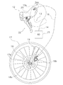
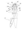
図1は、本考案の一実施形態による1対の自転車用制御装置12(図1にはドロップハンドルバー13の右側の制御装置のみ図示)が自転車のドロップハンドルバー13に取り付けられた状態を示している。なお、以下の説明では、自転車用制御装置を単に制御装置と記す。右側の制御装置12は、制御ケーブルとしてのシフトケーブル14を介してリアディレイラ15に連結される。シフトケーブル14はインナーケーブルを有するボーデン型の制御ケーブルである。右側の制御装置12は、油圧ホース16を介して前輪17を制動する制動装置18に連結されている。制動装置18は、油圧により動作する油圧式のディスクブレーキ装置である。制動装置18は、前輪17のハブ17aに一体回転可能に取り付けられるブレーキディスク18aと、自転車のフロントフォーク19に固定されブレーキディスク18aを挟持して制動するキャリパ18bと、を有する。また、図示しない左側の制御装置は、それぞれ図示しないシフトケーブルを介してフロントディレイラに連結され、油圧ホースを介して例えば、図示しない後輪の制動装置に連結されている。フロントディレイラ及びリアディレイラ15は変速装置の一例である。右側の制御装置12と左側の制動装置は、互いの鏡像であり、シフト位置の数が異なる点を除き、その構造及び動作はほぼ同一である。したがって、ここでは右側の制御装置12についてのみ、詳細に説明及び図示している。
FIG. 1 shows a state in which a pair of bicycle control devices 12 (only the control device on the right side of the
ここで、制御装置12の説明に使用するように、以下「前方、後方、上方、下方、垂直、水平、下、横」などの方向を示す用語は、本考案の制御装置12が装着された自転車の方向を表している。したがって、本考案を説明するこれらの用語は、本考案による制御装置12の装着された自転車を基準として解釈されなければならない。また、「右、左」は、制御装置12か装着された自転車を後方から見て右側に配置される場合を「右」とし、左側に配置される場合を「左」として記載する。
Here, as used in the description of the
自転車の大半の部品については、当該技術において周知であるので、自転車の部品に関する詳細は、本考案による制御装置12に関連する部品を除き、ここでは説明又は図示しない。さらに、ここでは図示、説明されていない、制動装置、変速装置、スプロケットなどを含む、従来の自転車の様々な部品を本考案に係る制御装置12と共に使用することもできる。
Since most parts of the bicycle are well known in the art, details regarding the parts of the bike are not described or illustrated here except for parts related to the
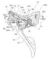
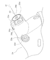
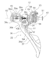
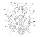
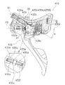
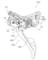
図2及び図3から明らかなように、制御装置12は、ハウジング部材20と、油圧発生部21と、制御レバー部材22と、変速操作機構23(図3参照)と、調整機構35と、を含む。ハウジング部材20は、自転車のドロップハンドルバー13の端部に形成される湾曲部13aに取付可能な取付部分20aと、取付部分20aが設けられ、ライダーが握持可能な握持部分20bと、を有する。取付部分20aは、公知のバンド形状の部材であり、取付部材20aをネジによって締め付けることによって制御装置12をドロップハンドルバー13に固定可能である。握持部分20bは、第1端20cと第2端20dとの間で長手方向に延びる。握持部分20bは、ポリアミド樹脂等の合成樹脂製又はアルミニウム等の金属製の握持部本体24と、握持部本体24の側面を覆う伸縮性を有する弾性体製のカバー部材25と、を有する。握持部本体24の上面は、握持部分20bを手で握りやすくするために下方に凹に湾曲して形成される。握持部本体24は、図2及び図3に示すように、第1端20c側に設けられる第1収納部24a(図2参照)と、第2端20d側に設けられる第2収納部24bと、第1収納部24aと第2収納部24bの間に設けられる第1ブラケット部24cと、を有する。第1収納部24aには、変速操作機構23が収納される。第2収納部24bには、制御レバー部材22の後述する第2ブラケット部39が収納される。第2収納部24bの上方に油圧発生部21が変速操作機構23と長手方向に間隔をあけて並べて配置される。第1ブラケット部24cは、左右一対設けられ、制御レバー部材22が第1軸芯X1回りに揺動可能に連結されるレバー軸26の両端を支持する。レバー軸26は、自転車の進行方向に対して略垂直な左右方向に配置されており、その軸芯が第1軸芯X1である。握持部本体24の第1端20c側は、ドロップハンドルバー13の湾曲部13aに沿うように湾曲する湾曲凹部24dが形成される。
As is apparent from FIGS. 2 and 3, the
油圧発生部21は、図2、図3及び図5に示すように、制動装置18に油圧を与えて制動装置18を制動動作させるために設けられる。油圧発生部21は、シリンダ30と、シリンダ30内を直線移動するピストン31と、ピストン31に連結されたロッド部32と、シリンダ30に連結されたリザーバ33(図2参照)と、第1油路34a(図5参照)と、出力ポート34b(図5参照)と、第2油路34c(図5参照)と、接続部34dと、ピストン位置調整機構35A(図2参照)と、を有する。油圧発生部21は、ピストン31をシリンダ30に対して、挿入する方向へ操作することによって、油圧を発生させる。
As shown in FIGS. 2, 3, and 5, the
シリンダ30は、握持部本体24に一体で形成される。シリンダ30は、例えば、握持部本体24の第2端20d側からの切削加工、又は型成形によって形成される。シリンダ30は、シリンダ軸芯A1を有する円筒形に形成される。シリンダ30は、ピストン31が移動する移動空間30aを有する。移動空間30aは、シリンダ30側の開口端部30bと、開口端部30bと反対側の第2端20d側の閉口端部30cと、を有する。閉口端部30cは、第1封止部材30dによって封止される。第1封止部材30dは、シリンダ30との隙間をシールするシール部材30eを有し、閉口端部30cにねじ込み固定される。閉口端部30cは、開口端部30bよりも高い位置(上方)に配置される。したがって、シリンダ軸芯A1は、前上がりに配置される。シリンダ軸芯A1と後述するケーブル巻取軸芯A2との、図3に示した側面視での交差角度αは、例えば、20度以上50度以下である。この範囲に交差角度αが設定されると、シリンダ30をケーブル巻取軸芯A2に対して傾けて配置しても握持部分20bの大型化を可及的に抑えることができる。この実施形態では、交差角度αは概ね30度である。なお、シリンダ軸芯A1は、ケーブル巻取軸芯A2よりも図3において紙面と直交する左右方向において、ケーブル巻取軸芯A2よりも手前側(左側)にあり、平面視では交差しない。
The
ピストン31は、概ね円柱形状の部材であり、ピストン31の外周面の両端部には、例えばOリングの形態の第1シール部材31a及び第2シール部材31bが装着される。第1シール部材31a及び第2シール部材31bは、シリンダ30の移動空間30aの内周面とピストン31の外周面との隙間をシールするために設けられる。なお、シール部材は、一つであってもよい。ピストン31は、制動レバー部材22の制動操作に応じて、図3に示すシリンダ30の先端に配置される第1位置と、第1位置よりも引っ込んだ図4に示す第2位置との間で移動空間30aを移動する。ピストン31は、第1戻しバネ42aによって第1位置に向け付勢される。
The
ロッド部32は、制動レバー部材22の制動方向の操作に応じてシリンダ30内に引っ込む。ロッド部32は、ピストン31に少なくとも第1軸芯X1と平行な軸芯回りに揺動自在に連結される。ロッド部32は、ロッド本体32aと、ロッド本体32aの先端に固定される2つ山のクレビス32bと、クレビス32bに装着された回動軸32cと、回動軸32cに回転自在に装着される左右一対のローラ32dと、を有する。左右一対のローラ32dは、ローラ32dの直径の1.5倍から2.5倍程度の距離間隔をあけて配置される。ロッド本体32aは、棒状の部材であり、ロッド本体32aのシリンダ装着側の一端32eは、他の部分よりも大径の球状に形成され、ピストン31に係合している。したがって、この実施形態では、ロッド部32は、シリンダ31に対して第1軸芯X1と平行な軸を含んで自在に揺動する。回動軸32cの両端部は、握持部本体24に設けられる案内溝24eに係合する。案内溝24eは、シリンダ軸芯Aに沿って配置される第1部分24fと、第1部分24fから上方に屈曲する第2部分24gと、を有する。ローラ32dは、制動レバー部材22に設けられる後述するカム部材41によって押圧される。したがって、ローラ32dがカム部材41によって押圧されると、ロッド部32の先端である回動軸32cはシリンダ軸芯A1に徐々に近づく。これにより、ロッド部32とシリンダ軸芯A2とがなす角度が徐々に小さくなり、ピストン31のシリンダ31内の移動がスムーズになる。
The
図2に示すように、リザーバ33は、油圧を発生する油を貯留可能である。リザーバ33は、制動装置18の摩擦材(例えばブレーキパッド)が磨耗し、油量が多く必要となった場合でも、リザーバ33から必要量の油を注入でき、また、油の温度の変化による膨張及び収縮によって制動装置18に与える圧力の変動を防止するために設けられる。リザーバ33は、リザーバ軸芯A3を有する円筒形に形成される。リザーバ33は、握持部分20bに長手方向と交差する左右方向にシリンダ30と間隔を隔てて並べて配置される。リザーバ軸芯A3は、シリンダ軸芯A1と実質的に平行であり、かつ実質的に同じ高さである。したがって、リザーバ33は、図2の紙面と直交する左右方向において、シリンダ30の奥側にシリンダ30と同じ傾きで形成され、リザーバ33も前上がりに握持部本体24の第2端側に形成される。リザーバ33は、第1端側の第1閉口端部33bと、第2端側の第2閉口端部33cとを有する。第1閉口端部33b及び第2閉口端部33cの少なくともいずれか、本件実施例では、第2端側の第2閉口端部33cは、リザーバ33に着脱可能に装着される第2封止部材33aによって封止される。第2封止部材33aは、接着、圧入、ネジ止め等の適宜の固定手段によってリザーバに固定される。リザーバ33は、図6に示すように、握持部本体24の第2端20d側において、第1油路34aと対向可能な側面に開口する注油孔33dを有する。注油孔33dの先端に着脱可能に装着される注油キャップ33eによって、注油孔33dは封止される。
As shown in FIG. 2, the
図5に示すように、第1油路34aは、シリンダ30とリザーバ33とを連通するために設けられる。第1油路34aは、ピストン31が第1位置に配置されるとき、第1シール部材31aよりも第2端20d側、かつピストン31が第2位置に配置されるとき第1シール部材31aよりもロッド部32側に配置される。この実施形態では、第1油路34aは、注油孔33dに対向可能に配置される。第1油路34aは、注油孔33dを介して形成可能なように注油孔33dよりも小径の複数の孔(例えば3つの孔)で構成される。
As shown in FIG. 5, the
出力ポート34bは、シリンダ30で発生した油圧を外部に供給するためのものである。出力ポート34bは、ピストン31が第2位置に配置されるとき、第1シール部材31aよりも第2端20d側に配置される。出力ポート34bは、シリンダ30の内周面と握持部本体24の側面とを貫通して形成される。出力ポート34の側面に貫通する部分は、プラグ34gによって封止されている。
The
第2油路34cは、出力ポート34bに連結される。第2油路34cは、出力ポート34bに連通して第1端20c側に屈曲して延びる。第2油路34cは、第1端20c及び第2端20dからあけられた配管孔34e内に配置される油圧管34fによって構成される。第2油路34cは、握持部本体24の上部が下方に凹に湾曲しているため、概ね扁平V字状に配置される。
The
接続部34dは、第2油路34cに接続され、第2油路34cを介して出力ポート34bと連通する。接続部34dは、制動装置18に連結可能な外部油圧ホース16(図1参照)と接続可能である。接続部34dは、第2油路34cの第1端20c側の端部、すなわちハウジング部材20の第1端20c側に配置される。
The connecting
本実施形態においては、調整機構35は、シリンダに対するピストンの初期位置を調整可能なピストン位置調整機構35A、及び制御レバーのハウジングに対する初期位置を調整可能な制御レバー位置調整機構35Bの双方を有している。
In the present embodiment, the
まず、ピストン位置調整機構35Aは、シリンダ30に対するピストンの第1位置(ピストンの初期位置の一例)を調整する機能と、第1操作レバー部36と後述するカム部材41と連結してピストン31を動作させる機能とを有する。ピストン位置調整機構35Aは、制御レバー部材22の後述する第1操作レバー部36と後述するカム部材41と、を連結する調整部材35aを有する。調整部材35aは、第1調整部材の一例である。調整部材35aは、第1操作レバー部36の後述する支持軸40を貫通する調整ボルト35bを有する。この場合には、調整ボルト35bは、第1調整ボルトの一例である。
First, the piston
調整ボルト35bの基端側の頭部は、支持軸40の貫通孔40aに引っ掛かる。調整ボルト35bの先端は、制御レバー部材22の後述するカム部材41に設けられる連結軸38にねじ込まれる。これにより、カム部材41の第1軸芯X1に対する初期位置を調整可能となり、ピストン31の第1位置を調整可能である。また、調整ボルト35bによって第2ブラケット部39とカム部材41とが連結され、第1操作レバー部36の第1軸芯回りの揺動操作に応じてカム部材41が回動する。したがって、調整ボルト35bは、ピストン31の第1位置を調整する機能と、第1制御レバー部材22とカム部材41とを連結する機能とを有する。
The head on the base end side of the
制御レバー位置調整機構35Bは、基本構成は、ピストン位置調整機構35Aと同様で、ハウジング部材20に対する第1制御レバー部材22の第1位置(制御レバー部材の初期位置の一例)を調整する機能と、第1操作レバー部36と後述するカム部材41と連結してピストン31を動作させる機能とを有する。ピストン位置調整機構35Aは、制御レバー部材22の後述する第1操作レバー部36と後述するカム部材41と、を連結する調整部材35aを有する。調整部材35aは、この場合には、第3調整部材の一例であり、調整ボルト35bは、第3調整ボルトの一例である。調整部材35aは、第1操作レバー部36の後述する支持軸40を貫通する調整ボルト35bを有する。調整ボルト35bの基端側の頭部は、支持軸40の貫通孔40aに引っ掛かる。調整ボルト35bの先端は、制御レバー部材22の後述するカム部材41に設けられる連結軸38にねじ込まれる。これにより、制御レバー部材22の第1軸芯X1に対する初期位置を調整可能となり、制御レバー部材22の第1位置、つまりは、制御レバー部材22を調整可能である。また、調整ボルト35bによって第2ブラケット部39とカム部材41とが連結され、第1操作レバー部36の第1軸芯回りの揺動操作に応じてカム部材41が回動する。したがって、調整ボルト35bは、第1操作レバー部36の第1位置を調整する機能と、第1制御レバー部材22とカム部材41とを連結する機能とを有する。
The control lever
さらに、調整機構35は、ピストン位置調整機構35Aと制御レバー位置調整機構35Bとの構成が同様であることから、調整ボルト35bによって第2ブラケット部39とカム部材41と第1操作レバー部36を連結させることによって、調整ボルト35bは、ピストン31の第1位置を調整する機能と、第1操作レバー部36の第1位置を調整する機能と、第1制御レバー部材22とカム部材41とを連結する機能とを有する。この場合には、調整部材35aは、第4調整部材の一例であり、調整ボルト35bは、第5調整ボルトの一例である。
Further, since the
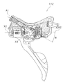
制御レバー部材22は、図2及び図7に示すように、第1操作レバー部36と、第2操作レバー部37と、カム部材41と、を有する。第1操作レバー部36は、支持部材36aと、支持部材36aに第2軸芯X2回りに揺動可能に連結されたレバー部36bと、を有する。支持部材36aは、ハウジング部材20に配置されたレバー軸26に第1軸芯X1回りに揺動可能に連結される。支持部材36aは、図2に示す第1初期位置から図4に示す揺動位置へ第1軸芯X1回りに揺動する。支持部材36aは、図7に示すように、レバー軸26の周囲に巻き付けられるねじりコイルバネの形態の第2戻しバネ42bによって第1初期位置に向けて付勢される。第2戻しバネ42bは、一端が握持部本体24の第1ブラケット部24cに係合し、他端が支持部材36aの後述する一対の側板39cの一方に係合する。
As shown in FIGS. 2 and 7, the
支持部材36aは、図2に示すように、板材を前後及び左右で折り曲げて形成された第2ブラケット部39と、第2ブラケット部39に支持された鍔付き中空の支持軸40と、を有する。第2ブラケット部39は、概ね矩形の基部39aと、基部39aの前後端を下方に平行に折り曲げて形成された前後一対の支持板39bと、基部39aの左右端を下方に平行に折り曲げて形成された左右一対の側板39cと、を有する。支持軸40は、一対の支持板39bに両端が支持される。一対の側板39cは、基部39aから後方に延びてレバー軸26に第1軸芯X1回りに揺動自在に支持される。支持軸40は、第1軸芯X1と平行ではない方向(例えば、食い違う方向)、すなわち自転車の進行方向に略平行な第2軸芯X2に沿って配置される。支持軸40は、レバー軸26よりも上方に配置される。支持軸40は、支持軸40の端部に螺合するナット43によって、支持部材36aの一対の支持板39bに固定される。前述したように、調整ボルト35bが支持軸40を貫通して配置される。
As shown in FIG. 2, the
図2及び図7に示すように、レバー部36bは、支持部材36aとともに、レバー軸26に第1軸芯X1回りに揺動可能に連結されるとともに、支持軸40に第2軸芯X2回りに揺動可能に連結される。レバー部36bは、前述の制動操作及びリアディレイラ15の一方向の変速操作のために設けられる。レバー部36bは、第2軸芯X2回りの揺動操作によって、変速操作機構23の後述するケーブル巻取部材50を操作し、シフトケーブル14を巻取る、すなわち引っ張ることで、リアディレイラ15をシフトアップ(又はシフトダウン)するように変速操作機構23に制御自在に連結される。また、第1軸芯X1回りの揺動操作によって油圧を発生することで、制動装置18を制動動作させる。
As shown in FIGS. 2 and 7, the
レバー部36bは、図2に示すように、装着端部分36cと、シフト操作部分36dと、自由端部分36eと、を有している。また、レバー部36bは、装着端部分36cとシフト操作部分36dの間に設けられた接触部36fを有する。接触部36fは、第1操作レバー部36が第2初期位置から第1変速位置に操作されると、第2操作レバー部37に接触可能である。これにより、第2操作レバー部37を、第1操作レバー部36に連動して揺動させることができる。レバー部36bは、図8に示すように、実線で示す第2初期位置と二点鎖線で示す第1変速位置との間を第2軸芯X2回りに移動する。装着端部分36cは、支持軸40に回動自在に連結される。シフト操作部分36dは、ハウジング部材20の先端部分から下方に向かって延びている。レバー部36bは巻取レバーの一例である。レバー部36bは、支持軸40に巻回された第3戻しバネ45によって第2初期位置に向けて付勢される。第3戻しバネ45は、一端が装着端部分36cに係合し、他端が支持部材36aの一対の基部39aに係合する。
As shown in FIG. 2, the
本実施形態においては、第2操作レバー部37は、支持軸40の先端部に第2軸芯X2回りに揺動可能に連結され、リアディレイラ15の他方向の変速操作のために設けられる。第2操作レバー部37は、ケーブル巻取部材50を操作し、シフトケーブル14を巻戻す、すなわち解除することで、リアディレイラ15をシフトダウン(又はシフトアップ)するように変速操作機構23に制御自在に連結される。
In the present embodiment, the second
図9に示すように、第2操作レバー部37は、実線で示す第3初期位置と、二点鎖線で示す第2変速位置との間を第2軸芯X2回りに移動する。第2操作レバー部37は、支持軸40の先端側に第2軸芯X2回りに回動自在に装着される。前述したように、第2操作レバー部37は、シフトケーブル14を解除するように、変速操作機構23に制御自在に連結される。第2操作レバー部37は解除操作レバーの一例である。第2操作レバー部37は、支持軸40とカム部材41の間に配置された第4戻しバネ46(図2参照)によって第3初期位置に向けて付勢される。第4戻しバネ46は、一端が第2操作レバー部37の装着端に係合し、他端が握持部本体24に係合する。
As shown in FIG. 9, the second
本実施形態においては、変速操作機構23は、基本的に、第1操作レバー部36を支持軸40の第2軸芯X2回りに回動するか、または第2操作レバー部37を支持軸40の第2軸芯X2回りに回動することによって実行される。
In the present embodiment, the speed
カム部材41は、図5に示すように、第1操作レバー部36の第1軸芯X1回りに揺動に連動して、第1軸芯X1回りに揺動して油圧発生部21のロッド部32を動作させるために設けられる。カム部材41は、左右一対のカム板41aと、一対のカム板41aと一体形成され、一対のカム板41aを連結する連結部41bと、を有する。一対のカム板41aは、一対のローラ32dと同じ間隔で左右方向に離れて配置される。カム板41aには、レバー軸26が貫通可能な貫通孔41cと、連結孔41dと、ローラ32dが接触するカム面41eと、が形成される。貫通孔41cは、カム部材41の下部に形成され、連結孔41dは、貫通孔41cの上方に形成される。連結孔41dには、ピストン位置調整機構35Aを介して第1操作レバー部36を連結する連結軸38が支持される。連結孔41dは、カム部材41が揺動するときに、連結孔41dと貫通孔41cとを結ぶ方向に連結軸38が移動可能となるようにわずかに長円形に形成される。カム面41eは、この実施形態では、カム部材41が揺動するとき、カム部材41の回転に対してピストン31の移動量が変化するように、具体的には、回転当初では、移動量を大きく、回転が進んだ段階では、移動量を小さくなるように、凹に湾曲して形成される。そうすることで、制動が効き始めまでが早く、制動が効き始めてからは、制動力の調整が容易となっている。
As shown in FIG. 5, the
カム部材41は、貫通孔41cを貫通するレバー軸26に第1軸芯X1回りに揺動可能に連結される。連結軸38は、軸芯方向の中央部に調整ボルト35bがねじ込まれるネジ孔38aが形成される。カム部材41は、レバー軸26に設けられる第2戻しバネ42b(図7参照)によって図5時計回りに付勢される。また、第1戻しバネ42aによっても図5時計回りに付勢される。
The
図7から図10を参照して変速操作機構23を簡単に説明する。しかし、変速操作機構23は、ここで説明される構造に限定されない。前述した第1操作レバー部36及び第2操作レバー部37を有する制御レバー部材22は、他の構成の変速操作機構を用いることができる。変速操作機構23は、ハウジング部材20の握持部本体24の第1端29c側に装着される。変速操作機構23は、ケーブル巻取部材50と、第1入力部材52と、第2入力部材54と、位置決め機構56と、を有する。ここで、握持部分20bの長手方向に延びるケーブル巻取軸51の中心をケーブル巻取軸芯A2と規定する。この実施形態では、ケーブル巻取軸芯A2は、第2軸芯X2と同軸芯である。
The speed
ケーブル巻取部材50には、シフトケーブル14のインナーケーブルが巻き付けられる。ケーブル巻取部材50は、ケーブル巻取軸芯A2回りにケーブル巻取軸51に回転自在に装着される。ケーブル巻取部材50は、図示しない戻しバネによって、ケーブル巻戻し方向に付勢されている。すなわち、戻しバネは、ケーブル巻取部材50をケーブル巻戻し方向に回転させるように付勢力を加える。ケーブル巻取部材50は、シフトケーブル14のインナーケーブルの端部に固定されたニップル(図示せず)を装着可能なケーブル装着部50aを有するほぼ円筒形状である。第1操作レバー部36が第2初期位置から第1変速位置に向けて操作されると、ケーブル巻取部材50は、ケーブル巻取軸芯A2回りの第1回転方向R1(図10参照)に回転し、インナーケーブルを巻き取る。また、第2操作レバー部37が第3初期位置から第2変速位置に向けて操作されると、ケーブル巻取部材50は、ケーブル巻取軸芯A2回りの第2回転方向R2(図10参照)に回転し、インナーケーブルを繰り出す。
An inner cable of the
第1入力部材52及び第2入力部材54は、変速操作を実行可能に第1操作レバー部36及び第2操作レバー部37に各別に連結される。第1入力部材52は、第1操作レバー部36の第2軸芯X2回りの揺動に連動してケーブル巻取軸芯A2回りに揺動する。第1入力部材52の先端部は、図7に示すように、レバー部36bの接触部36fに接触可能である。これにより、第1操作レバー部36が第2初期位置から第1変速位置に第2軸芯X2回りに揺動操作されると、第1入力部材52は、ケーブル巻取軸芯A2回りに揺動する。
The
第2入力部材54は、第2操作レバー部37の第2軸芯X2回りの揺動に連動してケーブル巻取軸芯A2回りに揺動する。第2入力部材54の先端部は、第2操作レバー部37の中間部分に接触可能である。これにより、第2操作レバー部37が第3初期位置から第2変速位置に第2軸芯X2回りに揺動操作されると、第2入力部材54は、ケーブル巻取軸芯A2回りに揺動する。
The
位置決め機構56は、ケーブル巻取部材50の回転位置を、変速段に応じて位置決めする機構である。位置決め機構56は、巻取爪58と、解除爪60と、巻取プレート62と、解除プレート62と、位置決め爪66と、停止爪68と、位置決めプレート70と、を有する。巻取爪58は、第1入力部材52に揺動可能に設けられる。巻取爪58は、第1操作レバー部36を第2初期位置から第1変速位置に向けて操作すると、第1入力部材52が連動して揺動する。これにより、巻取爪58がケーブル巻取部材を戻しバネの付勢力に抗してケーブル巻取部材50を第1回転方向R1に回転させる。
The
解除爪60は、第2入力部材54に揺動可能に設けられる。解除爪60は、第2操作レバー部37を第3初期位置から第2変速位置に向けて操作すると、第2入力部材54が連動して揺動する。これにより、解除爪60がケーブル巻取部材50から外れ、ケーブル巻取部材50を戻しバネの付勢力によって第2回転方向R2に回転させる。
The
巻取プレート62及び位置決めプレート70は、ケーブル巻取部材50に装着され、ケーブル巻取部材50と一体で揺動する。巻取プレート62は、複数の巻取歯を有する。複数の巻取歯は巻取爪58に選択的に係合する。これにより、ケーブル巻取部材50が第1回転方向R1に回転する。
The winding
位置決めプレート70は、複数の位置決め歯を有する。複数の位置決め歯は、位置決め爪66に選択的に係合する。これにより、第1操作レバー部36の巻取操作又は第2操作レバー部37の解除操作後に、ケーブル巻取部材50を所定の変速位置に保持する。
The
解除プレート62は、ケーブル巻取部材50を第2回転方向R2に回転させるために、位置決め爪66及び停止爪68が位置決めプレート70から解除プレート62に選択的に係合及び係合解除するように、解除爪60によって第1回転方向R1に回転される
図の実施形態による第1操作レバー部36では、ドロップハンドルバー13又は握持部分20bの湾曲部分を手で握ったまま、第1操作レバー部36を第1初期位置から制動位置にまで回動可能である。第1操作レバー部36は、第1軸芯X1を中心に回動する。第1操作レバー部36のこの回動によって、油圧発生部21のピストン31が押圧されてシリンダ30内に油圧が発生し、油圧によって制動装置18が動作し、自転車が制動される。
The
第1操作レバー部36は、リアディレイラ15の変速段を例えば低速側にシフトダウンするために、第2軸芯X2を中心に回動し第2初期位置から変速位置に向けて横方向に揺動可能である。第1操作レバー部36が解除されると、第3戻しバネ45の付勢力によって第2初期位置に戻される。第2操作レバー部37は、例えば変速段を高速側にシフトアップするために、静止位置から横方向に揺動可能であり、レバーが解除されると第4戻しバネ46の付勢力によって、第3初期位置まで戻される。
The first
第1操作レバー部36が変速のために揺動させられた際、第2操作レバー部37は、第1操作レバー部36に対して移動する代わりに、第1操作レバー部36と共に揺動する。これによって、第1操作レバー部36は、第2操作レバー部37に妨げられることなく揺動が可能となる。
When the first
ライダーがドロップハンドルバー13の湾曲部分の最下部位置をつかみながら、例えば、湾曲部分を握っている手の中指及び人指し指を延ばし、第1操作レバー部36に指を掛けて、第1操作レバー部36を制動位置、すなわち湾曲部13aに向かう方向へ引き寄せることができる。このレバー操作によって、変速操作機構23は、支持部材36aとともに、第1軸芯X1の回りに回動する。第1操作レバー部36のこの回動運動によって、油圧が発生し自転車にプレーキが掛けられる。
While the rider grasps the lowermost position of the curved portion of the
<第1変形例>
なお、以降の説明については、上記実施形態と異なる構成だけを説明するとともに、図面に符号を付し、その他の上記実施形態と同様な構成については、構成及び動作の説明、並びに図面への符号の付与は省略する。
<First Modification>
In the following description, only the configuration different from the above-described embodiment will be described, and the reference numerals are attached to the drawings. For the same configurations as the other embodiments described above, the description of the configuration and operation, and the reference numerals to the drawings Is omitted.
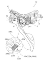
上記実施形態では、第2軸芯X2とケーブル巻取軸芯A2とが同芯であったが、本考案はこれに限定されない。図11に示すように、制御装置112において、第2軸芯X2とケーブル巻取軸芯A2とを異なる軸芯としてもよい。図11では、変速操作機構123のケーブル巻取軸芯A2は、制御レバー部材122の第2軸芯X2よりも下方に配置される。なお、ケーブル巻取軸芯A2と第2軸芯X2とを交差して配置してもよい。
In the said embodiment, although 2nd axis X2 and cable winding axis A2 were concentric, this invention is not limited to this. As shown in FIG. 11, in the
<第2変形例>
上記実施形態では、調整機構35(ピストン位置調整機構35A及び制御レバー位置調整機構35B)の調整ボルト35bを、支持軸40を貫通して第2軸芯X2に沿って配置したが、本考案はこれに限定されない。図12に示すように、第2変形例の制御装置212では、図12に示すように、調整機構235(ピストン位置調整機構235A及び制御レバー位置調整機構235B)の調整部材235a(第2調整部材、第4調整部材の一例)である調整ボルト235b(第2調整ボルト、第4調整ボルト、第6調整ボルトの一例)を、第1軸芯X1を有するレバー軸26の近くに設ける。調整ボルト235bは、レバー部36bに形成されたネジ孔236gねじ込まれ、先端部がカム部材241の連結部241bに接触する。これにより、第1操作レバー部236の第2初期位置が変化しかつピストン31の位置がシリンダ30への挿入方向に移動する。カム部材241は、シリンダ30に配置された第1戻しバネ42aによって図12時計回りに付勢される。この場合には、支持軸40の内部を貫通して第2ブラケット部39とカム部材141とを連結する調整ボルトは不要である。また、支持部材とカム部材とを一体形成してもよい。この場合にも支持部材を貫通する調整ボルトは不要である。
<Second Modification>
In the above embodiment, the adjusting
<第3変形例>
図13に示すように、第3変形例による制御装置312では、調整機構335(ピストン位置調整機構335A及び制御レバー位置調整機構335B)の調整部材335a(第1調整部材の一例)がカム部材341に装着されたウォームギアボルト335bで構成される。ウォームギアボルト335bには、外周面にウォームギア歯335cが形成される。支持部材336aの第1ブラケット部339一対の側板339cの一方には、ウォームギア歯335cに噛み合うウォームホイール歯339dが形成される。この場合には、制御レバー部材22の第2ブラケット部339とカム部材341とを連結するために、上記実施形態の調整ボルトを連結ボルトとして用いる。
<Third Modification>
As shown in FIG. 13, in the control device 312 according to the third modification, the
<第4変形例>
図14に示すように、第4変形例による制御装置412では、調整機構435(ピストン位置調整機構435A又は制御レバー位置調整機構435B)は、ピストン31と制御レバー部材422とを連結し、制御レバー部材22とピストンとの相対位置を調整可能な調整部材435aを有する。調整部材435aは、第2調整部材の一例である。具体的には、ピストン31を、ロッド部432を介して制御レバー部材422の支持部材436aの第2ブラケット部439cに連結している。したがってカム部材は設けられていない。
<Fourth Modification>
As shown in FIG. 14, in the
ロッド部432は、ローラを有しておらず、クレビス432bに第2ブラケット部439の一対の側板439cが揺動自在に連結される。ロッド本体432aは、シリンダ30に連結される第1ロッド本体432eと、第1ロッド本体432eと間隔を隔てて配置された第2ロッド本体432fと、を有する。第2ロッド本体432fにクレビス432bが設けられる。調整部材435aは、第1ロッド本体432eと第2ロッド本体432fとに螺合して、ロッド部432の長さを調整する調整ネジ435bを有する。なお、第1ロッド本体432eは、軸芯回りの回転が規制されている。
The
調整ネジ435bは、第1ロッド本体432eに螺合する第1雄ネジ部435cと、第2ロッド本体432fに螺合する第2雄ネジ部435dと、第1雄ネジ部435cと第2雄ネジ部435dとの間に配置される回動操作用の非円形(例えば六角形)のつまみ部435eと、を有する。第1雄ネジ部435cは、例えば右ねじであり、第2雄ネジ部435dは、例えば左ネジである。
The adjustment screw 435b includes a first
このような構成の調整機構435(ピストン位置調整機構435A又は制御レバー位置調整機構435B)では、つまみ部435eを手又は工具を用いて第1方向(例えば、ピストンに向かって時計回りの方向)に回すと、第1ロッド本体432eと第2ロッド本体432fとが互いに接近する方向に移動し、ロッド部432の長さが短くなる。これにより、ピストン31の第1位置が後退(図14右側の移動)する。また、つまみ部435eを手又は工具を用いて第1方向とは逆の第2方向に回すと、第1ロッド本体432eと第2ロッド本体432fとが互いに離反する方向に移動し、ロッド部432の長さが長くなる。これにより、ピストン31の第1位置が前進(図14左側の移動)する。このような構成においても、ピストン31の第1位置を調整できる。
In the adjustment mechanism 435 (piston
なお、第4変形例では、ピストンを第1位置に付勢する第1戻しバネ42aと制御レバー部材422を第1初期位置に戻す第2戻しバネ42bの付勢力の大きさによってピストン位置調整機構435A又は制御レバー位置調整機構435Bが実現される。通常は、第2戻しバネ42bの付勢力が大きいため、ピストン位置調整機構435Aが実現される。第2戻しバネ42bの付勢力が第1戻しバネ42aの付勢力よりも小さい場合は、制御レバー位置調整機構435Bが実現される。
In the fourth modification, the piston position adjusting mechanism is based on the magnitude of the biasing force of the
<第5変形例>
図15に示すように、制御装置512において、制御レバー部材522の第2操作レバー部537は、巻取操作レバー537aと解除操作レバー537bと、を有する。第1操作レバー部536は、第1軸芯X1回りにのみ揺動し、第2軸芯X2回りには揺動しない。巻取操作レバー537aは、第2軸芯X2回りの揺動によって第1入力部材52を揺動させ、ケーブル巻取部材50を巻取方向に動作させる。解除操作レバー537bは、第2軸芯X2回りの揺動によって第2入力部材54を揺動させケーブル巻取部材50を巻取方向と反対の解除方向に動作させる。
<Fifth Modification>
As shown in FIG. 15, in the
<第6変形例>
図16に示すように、制御装置612において、制御レバー部材622の第2操作レバー部材637は、第2軸芯X2回りではなく、第2軸芯X2よりも先端側で第1操作レバー部636に配置される支持軸670の第3軸芯X3回りに揺動する。支持軸670は、第1操作レバー部636に固定される。
<Sixth Modification>
As shown in FIG. 16, in the
<他の実施形態>
以上、本考案の一実施形態について説明したが、本考案は上記実施形態に限定されるものではなく、考案の要旨を逸脱しない範囲で種々の変更が可能である。特に、本明細書に書かれた複数の実施形態及び変形例は必要に応じて任意に組合せ可能である。
<Other embodiments>
As mentioned above, although one Embodiment of this invention was described, this invention is not limited to the said embodiment, A various change is possible in the range which does not deviate from the summary of invention. In particular, a plurality of embodiments and modifications described in this specification can be arbitrarily combined as necessary.
(a)上記実施形態では、油圧によって動作可能な制動装置としてディスクブレーキ装置を例示したが、本考案により制御される制動装置は、ディスクブレーキ装置に限定されない。本考案は、油圧によって動作可能な全ての自転車用制動装置を制御する制御装置に適用できる。例えば、油圧によって動作するキャリパブレーキ、ドラムブレーキ等の制動装置を制御する自転車用制御装置にも本考案を適用できる。 (A) In the above embodiment, the disk brake device is exemplified as a brake device operable by hydraulic pressure. However, the brake device controlled by the present invention is not limited to the disk brake device. The present invention can be applied to a control device for controlling all bicycle braking devices operable by hydraulic pressure. For example, the present invention can be applied to a bicycle control device that controls a braking device such as a caliper brake or a drum brake that operates by hydraulic pressure.
(b)上記実施形態では、油圧を発生する油を貯留するリザーバを設けて、シリンダ内の油量が減った場合に、シリンダへの油の注入を可能にするとともに、油の温度変化にかかわらず制動特性の変化を抑えるように構成したが、リザーバを有さない自転車用制御装置にも本考案を適用できる。 (B) In the above-described embodiment, a reservoir for storing oil that generates hydraulic pressure is provided, so that when the amount of oil in the cylinder is reduced, oil can be injected into the cylinder and the temperature of the oil can be changed. However, the present invention can be applied to a bicycle control device that does not have a reservoir.
(c)上記実施形態の油圧発生部21では、ピストン31を押す、すなわちピストン31をシリンダ30内に挿入するように移動させて油圧を発生しているが、本考案はこれに限定されない。例えば、ピストンを引く、すなわち、ピストンをシリンダから引き出すことによって油圧を発生してもよい。この場合、ピストンと第1操作レバー部との連結部分であるロッド部に引っ張り力だけが作用する。このため、ロッド部に座屈が生じなくなり、連結部分の剛性を低くできロッド部の軽量化を図れる。ただし、この場合には、ロッドのシリンダの面積からロッドの面積を引いた面積に油圧を乗じた力が発生するため、シリンダを上記実施形態のものよりも大径にする必要がある。
(C) In the hydraulic
(d)上記実施形態では、第1戻しバネ42aの一端をピストン31の端面に接触させたが、図17に示すように、第1戻しバネ742aの一端をピストン731に形成した収納穴731aに収納してもよい。これにより、第2位置にピストン731が移動したときのバネ収納空間を容易に確保できる。このため、バネの設計の自由度が高くなる。
(D) In the above embodiment, one end of the
(e)上記実施形態では、制御レバー部材22を、制動操作及び変速操作用の第1操作レバー部36と、変速操作用の第2操作レバー部37とで構成したが、1本の操作レバー部の第1軸芯回りの揺動によって制動操作を行い、第2軸芯回りの一方向の揺動によって第1の変速操作(例えばシフトダウン操作)を行い、第2軸芯回りの他方向の揺動によって第2の変速操作(例えばシフトアップ操作)を行ってもよい。
(E) In the above embodiment, the
(f)上記実施形態では、第1操作レバー部36と油圧発生部21とに第1戻しバネ42aと、第2戻しバネ42bとをそれぞれ設けたが、第1戻しバネ42aだけを設けてもよい。
(F) In the above embodiment, the
(g)上記実施形態では、調整ボルト35bを介してカム部材41を第1操作レバー部36に連結しているが、本考案はこれに限定されない。カム部材を第1操作レバー部に一体的に揺動可能に連結してもよい。例えば、第1ブラケット部39にカム部材を一体形成してもよい。この場合、ピストン位置調整機構を設ける場合、第2変形例から第4変形例に示すような構成にすればよい。
(G) In the above embodiment, the
ここでは、本考案の選択された実施形態を説明、図示しているが、本開示から本技術に精通するものには明らかであるが、請求項で定義された本考案の意図または範囲から離れることなく、様々な修正、変更を加えることができる。さらに、本考案による複数の実施形態の説明は、図示のみを目的とし、附随する請求項や同等の請求項による定義によって本考案を制限するものではない。 While selected embodiments of the present invention have been illustrated and illustrated herein, it will be apparent to those skilled in the art from this disclosure that they depart from the spirit or scope of the invention as defined in the claims. Various modifications and changes can be made without any changes. Furthermore, the description of the embodiments of the present invention is for illustration purposes only and is not intended to limit the present invention by the definitions of the appended claims or equivalent claims.
12,112,212,312,412,512,612 自転車用制御装置
13 ドロップハンドルバー
14 シフトケーブル(制御ケーブルの一例)
15 リアディレイラ(変速装置の一例)
18 制動装置
20 ハウジング部材
20a 取付部分
20b 握持部分
20c 第1端
20d 第2端
21 油圧発生部
22,122,522、622 制御レバー部材
23,123 変速操作機構
24e 案内溝
30 シリンダ
31,731 ピストン
32、432 ロッド部
32d ローラ(ローラ部の一例)
36,236,536,636 第1操作レバー部
41,141,241,341 カム部材
X1 第1軸芯
X2 第2軸芯
12, 112, 212, 312, 412, 512, 612
15 Rear derailleur (an example of a transmission)
DESCRIPTION OF
36, 236, 536, 636 First
Claims (7)
第1端と第2端との間で長手方向に延びる握持部分と、前記握持部分の第1端側に設けられ前記ハンドルバーに取付可能な取付部分と、を有するハウジング部材と、
前記ハウジング部材に設けられ、前記変速装置に連結可能な制御ケーブルを制御するための変速操作機構と、
前記ハウジング部材に設けられ前記変速操作機構よりも前記握持部分の前記第2端側に配置されるシリンダと、前記シリンダ内を移動可能なピストンと、前記ピストンに連結されるロッド部と、を有し、前記制動装置を制御するための油圧発生部と、
前記ロッド部を動作させるカム部材と、前記カム部材に連結され、前記ハウジング部材に対して第1軸芯回りに揺動可能であり、前記第1軸芯回りの揺動によって前記カム部材を動作させる第1操作レバー部と、を有する制御レバー部材と、
を備える自転車用制御装置。 A bicycle control device that can be mounted on a bicycle handlebar and that can control a braking device and a transmission,
A housing member having a gripping portion extending in a longitudinal direction between the first end and the second end; and an attachment portion provided on the first end side of the gripping portion and attachable to the handlebar;
A speed change operation mechanism for controlling a control cable provided on the housing member and connectable to the speed change device;
A cylinder provided in the housing member and disposed closer to the second end side of the gripping portion than the speed change operation mechanism; a piston movable within the cylinder; and a rod portion coupled to the piston. A hydraulic pressure generator for controlling the braking device;
A cam member for operating the rod portion, coupled to the cam member, and swingable about a first axis with respect to the housing member, and operating the cam member by swinging about the first axis A control lever member having a first operating lever portion,
A bicycle control device comprising:
Priority Applications (10)
| Application Number | Priority Date | Filing Date | Title |
|---|---|---|---|
| JP2012007808U JP3182209U (en) | 2012-12-26 | 2012-12-26 | Bicycle control device |
| TW102120151A TWI568624B (en) | 2012-12-26 | 2013-06-06 | Bicycle control device |
| US14/094,733 US9718515B2 (en) | 2012-12-26 | 2013-12-02 | Bicycle control device |
| CA2835846A CA2835846A1 (en) | 2012-12-26 | 2013-12-09 | Bicycle control device |
| AU2013270513A AU2013270513A1 (en) | 2012-12-26 | 2013-12-11 | Bicycle control device |
| DE102013021514.5A DE102013021514A1 (en) | 2012-12-26 | 2013-12-18 | Bicycle control device |
| EP13198129.2A EP2749489B1 (en) | 2012-12-26 | 2013-12-18 | Bicycle control device |
| IT002178A ITMI20132178A1 (en) | 2012-12-26 | 2013-12-20 | BICYCLE CONTROL DEVICE |
| CN201310726620.9A CN103895802A (en) | 2012-12-26 | 2013-12-25 | Bicycle control device |
| CN201910237604.0A CN110254594A (en) | 2012-12-26 | 2013-12-25 | Bicycle control |
Applications Claiming Priority (1)
| Application Number | Priority Date | Filing Date | Title |
|---|---|---|---|
| JP2012007808U JP3182209U (en) | 2012-12-26 | 2012-12-26 | Bicycle control device |
Publications (1)
| Publication Number | Publication Date |
|---|---|
| JP3182209U true JP3182209U (en) | 2013-03-14 |
Family
ID=49911222
Family Applications (1)
| Application Number | Title | Priority Date | Filing Date |
|---|---|---|---|
| JP2012007808U Expired - Fee Related JP3182209U (en) | 2012-12-26 | 2012-12-26 | Bicycle control device |
Country Status (9)
| Country | Link |
|---|---|
| US (1) | US9718515B2 (en) |
| EP (1) | EP2749489B1 (en) |
| JP (1) | JP3182209U (en) |
| CN (2) | CN103895802A (en) |
| AU (1) | AU2013270513A1 (en) |
| CA (1) | CA2835846A1 (en) |
| DE (1) | DE102013021514A1 (en) |
| IT (1) | ITMI20132178A1 (en) |
| TW (1) | TWI568624B (en) |
Cited By (2)
| Publication number | Priority date | Publication date | Assignee | Title |
|---|---|---|---|---|
| US9321506B2 (en) | 2013-10-01 | 2016-04-26 | Shimano Inc. | Bicycle hydraulic operating device |
| US9821881B2 (en) | 2013-10-01 | 2017-11-21 | Shimano Inc. | Bicycle hydraulic operating device |
Families Citing this family (8)
| Publication number | Priority date | Publication date | Assignee | Title |
|---|---|---|---|---|
| JP3182206U (en) * | 2012-12-26 | 2013-03-14 | 株式会社シマノ | Bicycle control device |
| JP3182205U (en) * | 2012-12-26 | 2013-03-14 | 株式会社シマノ | Bicycle control device |
| JP3182208U (en) * | 2012-12-26 | 2013-03-14 | 株式会社シマノ | Bicycle control device |
| DE102017002789A1 (en) * | 2016-04-21 | 2017-10-26 | Shimano Inc. | Bicycle actuator |
| US10407122B2 (en) * | 2016-04-25 | 2019-09-10 | Shimano Inc. | Bicycle operating device |
| US10189532B2 (en) * | 2016-07-12 | 2019-01-29 | Shimano Inc. | Bicycle operating device |
| US10343744B2 (en) | 2016-05-23 | 2019-07-09 | Shimano Inc. | Bicycle operating device |
| US10988209B1 (en) * | 2020-03-11 | 2021-04-27 | Sram, Llc | Bicycle control system |
Family Cites Families (33)
| Publication number | Priority date | Publication date | Assignee | Title |
|---|---|---|---|---|
| US4175648A (en) | 1977-10-20 | 1979-11-27 | Sandor Sule | Device for the braking of bicycles |
| US4391353A (en) | 1981-01-23 | 1983-07-05 | Mathauser William R | Hand operated hydraulic bicycle brake |
| GB2154292A (en) * | 1984-02-09 | 1985-09-04 | Kuo Chuo Chang | Hydraulic control system for motorcycle or bicycle brake or clutch |
| US4665803A (en) | 1985-04-24 | 1987-05-19 | Mathauser William R | Hydraulic brake actuating device for bicycles |
| US4921081A (en) | 1988-12-22 | 1990-05-01 | Autra-Bike Co., Inc. | Hydraulic brake apparatus for bicycles |
| IT1245445B (en) | 1991-03-11 | 1994-09-20 | Campagnolo Srl | TRANSMISSION AND BRAKE CONTROL UNIT FOR A BICYCLE |
| DE4216188A1 (en) * | 1992-04-03 | 1993-10-07 | Pellyfren Ag Schaffhausen | Hydraulic bicycle brake actuator - uses multiple cam wheel to compensate for brake block wear |
| JP3742143B2 (en) * | 1996-04-19 | 2006-02-01 | 株式会社三共製作所 | Fluctuating torque canceling device |
| US6057520A (en) * | 1999-06-30 | 2000-05-02 | Mcnc | Arc resistant high voltage micromachined electrostatic switch |
| US7650813B2 (en) | 2005-05-19 | 2010-01-26 | Shimano Inc. | Position control mechanism for bicycle control device |
| EP1919764A1 (en) * | 2005-08-30 | 2008-05-14 | Canyon Bicycles GmbH | Racing bicycle brake and brake device for racing bicycle brakes |
| US7516616B2 (en) * | 2006-06-09 | 2009-04-14 | Shimano Inc. | Bicycle hydraulic brake actuation device |
| US7540147B2 (en) | 2007-04-10 | 2009-06-02 | Shimano Inc. | Master cylinder lever for a hydraulic brake with dead-band adjustment mechanism |
| US8549956B2 (en) * | 2007-06-25 | 2013-10-08 | Shimano Inc. | Bicycle control device |
| US8863611B2 (en) * | 2008-10-08 | 2014-10-21 | Sram, Llc | Bicycle control device |
| US9132886B2 (en) | 2009-10-07 | 2015-09-15 | Shimano Inc. | Shift operating device |
| US8201670B2 (en) | 2009-12-17 | 2012-06-19 | Shimano Inc. | Bicycle hydraulic brake actuation device |
| TWM386235U (en) | 2010-03-30 | 2010-08-11 | Shimano Kk | Brake rod device of bike |
| JP5746482B2 (en) | 2010-06-24 | 2015-07-08 | 株式会社ハーマン | Cooker and cooker safety system |
| US8464844B2 (en) * | 2010-12-28 | 2013-06-18 | Sram, Llc | Hydraulic brake lever |
| US9840304B2 (en) * | 2011-03-03 | 2017-12-12 | Shimano Inc. | Hydraulic brake actuation device |
| US20120240715A1 (en) | 2011-03-24 | 2012-09-27 | Tektro Technology Corporation | Braking device with hidden hydraulic cylinder |
| US8752450B2 (en) * | 2011-06-14 | 2014-06-17 | Shimano Inc. | Bicycle component operating device |
| US9381975B2 (en) * | 2011-06-14 | 2016-07-05 | Shimano Inc. | Bicycle shift operating device |
| US9321505B2 (en) | 2012-03-30 | 2016-04-26 | Shimano Inc. | Bicycle hydraulic component operating device |
| JP3181557U (en) * | 2012-11-29 | 2013-02-14 | 株式会社シマノ | Bicycle control device |
| JP3182208U (en) * | 2012-12-26 | 2013-03-14 | 株式会社シマノ | Bicycle control device |
| JP3182210U (en) * | 2012-12-26 | 2013-03-14 | 株式会社シマノ | Bicycle control device |
| JP3182207U (en) * | 2012-12-26 | 2013-03-14 | 株式会社シマノ | Bicycle control device |
| JP3182205U (en) * | 2012-12-26 | 2013-03-14 | 株式会社シマノ | Bicycle control device |
| JP3182206U (en) * | 2012-12-26 | 2013-03-14 | 株式会社シマノ | Bicycle control device |
| DE102013200824A1 (en) * | 2013-01-18 | 2014-07-24 | Gustav Magenwirth Gmbh & Co. Kg | Encoder fitting for a hydraulic disc brake |
| US9821881B2 (en) * | 2013-10-01 | 2017-11-21 | Shimano Inc. | Bicycle hydraulic operating device |
-
2012
- 2012-12-26 JP JP2012007808U patent/JP3182209U/en not_active Expired - Fee Related
-
2013
- 2013-06-06 TW TW102120151A patent/TWI568624B/en active
- 2013-12-02 US US14/094,733 patent/US9718515B2/en active Active
- 2013-12-09 CA CA2835846A patent/CA2835846A1/en not_active Abandoned
- 2013-12-11 AU AU2013270513A patent/AU2013270513A1/en not_active Abandoned
- 2013-12-18 DE DE102013021514.5A patent/DE102013021514A1/en not_active Withdrawn
- 2013-12-18 EP EP13198129.2A patent/EP2749489B1/en active Active
- 2013-12-20 IT IT002178A patent/ITMI20132178A1/en unknown
- 2013-12-25 CN CN201310726620.9A patent/CN103895802A/en active Pending
- 2013-12-25 CN CN201910237604.0A patent/CN110254594A/en active Pending
Cited By (2)
| Publication number | Priority date | Publication date | Assignee | Title |
|---|---|---|---|---|
| US9321506B2 (en) | 2013-10-01 | 2016-04-26 | Shimano Inc. | Bicycle hydraulic operating device |
| US9821881B2 (en) | 2013-10-01 | 2017-11-21 | Shimano Inc. | Bicycle hydraulic operating device |
Also Published As
| Publication number | Publication date |
|---|---|
| ITMI20132178A1 (en) | 2014-06-27 |
| AU2013270513A1 (en) | 2014-07-10 |
| EP2749489A1 (en) | 2014-07-02 |
| EP2749489B1 (en) | 2016-03-30 |
| DE102013021514A1 (en) | 2014-06-26 |
| US9718515B2 (en) | 2017-08-01 |
| TW201425128A (en) | 2014-07-01 |
| CN103895802A (en) | 2014-07-02 |
| US20140174234A1 (en) | 2014-06-26 |
| TWI568624B (en) | 2017-02-01 |
| CA2835846A1 (en) | 2014-06-26 |
| CN110254594A (en) | 2019-09-20 |
Similar Documents
| Publication | Publication Date | Title |
|---|---|---|
| JP3182207U (en) | Bicycle control device | |
| JP3182210U (en) | Bicycle control device | |
| JP3182206U (en) | Bicycle control device | |
| JP3182205U (en) | Bicycle control device | |
| JP3182209U (en) | Bicycle control device | |
| JP3182208U (en) | Bicycle control device | |
| JP3181557U (en) | Bicycle control device |
Legal Events
| Date | Code | Title | Description |
|---|---|---|---|
| R150 | Certificate of patent or registration of utility model |
Ref document number: 3182209 Country of ref document: JP Free format text: JAPANESE INTERMEDIATE CODE: R150 Free format text: JAPANESE INTERMEDIATE CODE: R150 |
|
| FPAY | Renewal fee payment (event date is renewal date of database) |
Free format text: PAYMENT UNTIL: 20160220 Year of fee payment: 3 |
|
| R250 | Receipt of annual fees |
Free format text: JAPANESE INTERMEDIATE CODE: R250 |
|
| R250 | Receipt of annual fees |
Free format text: JAPANESE INTERMEDIATE CODE: R250 |
|
| R250 | Receipt of annual fees |
Free format text: JAPANESE INTERMEDIATE CODE: R250 |
|
| R250 | Receipt of annual fees |
Free format text: JAPANESE INTERMEDIATE CODE: R250 |
|
| R250 | Receipt of annual fees |
Free format text: JAPANESE INTERMEDIATE CODE: R250 |
|
| R250 | Receipt of annual fees |
Free format text: JAPANESE INTERMEDIATE CODE: R250 |
|
| LAPS | Cancellation because of no payment of annual fees |