JP3146942U - Dispensing assembly for dispensing fluid - Google Patents
Dispensing assembly for dispensing fluid Download PDFInfo
- Publication number
- JP3146942U JP3146942U JP2008004499U JP2008004499U JP3146942U JP 3146942 U JP3146942 U JP 3146942U JP 2008004499 U JP2008004499 U JP 2008004499U JP 2008004499 U JP2008004499 U JP 2008004499U JP 3146942 U JP3146942 U JP 3146942U
- Authority
- JP
- Japan
- Prior art keywords
- fluid
- valve
- control
- channel
- membrane
- Prior art date
- Legal status (The legal status is an assumption and is not a legal conclusion. Google has not performed a legal analysis and makes no representation as to the accuracy of the status listed.)
- Expired - Fee Related
Links
Images


Abstract
【課題】流体サンプルを個別の量の任意の組合せで計量分配する流体処理装置を提供する。
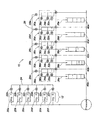
【解決手段】流体処理装置10は、選択した材料を所定の出力量だけ選択したウェルに迅速かつ効率的に計量分配するように構成されている。対応するソース貯留部20a、20b、20c、20d、20e、および20f内にいくつかの異なる材料12が提供され、材料が選択的に供給されてさらに処理される際に通過する材料バルブ22a、22b、22c、22d、22eおよび22fに接続されている。材料は、一度に1つ選択することができ、その後、材料チャネル24に流入する。チャネル24は主充填チャネル26に送られる。主充填チャネル26は、計量チャンバ30a、30b、30c、30d、および30eに接続され、そこで流れは充填バルブ28a、28b、28c、28d、および28eを介して個別に制御され、各々の選択した計量チャンバを所望の材料で完全に充填する。
【選択図】図1A fluid treatment apparatus for dispensing fluid samples in any combination of discrete quantities.
A fluid processing apparatus is configured to quickly and efficiently dispense selected material to a selected well by a predetermined output amount. Several different materials 12 are provided in the corresponding source reservoirs 20a, 20b, 20c, 20d, 20e, and 20f, and material valves 22a, 22b that are passed through when the materials are selectively fed and further processed. , 22c, 22d, 22e and 22f. The materials can be selected one at a time and then flow into the material channel 24. Channel 24 is routed to main fill channel 26. The main fill channel 26 is connected to metering chambers 30a, 30b, 30c, 30d, and 30e, where flow is individually controlled via fill valves 28a, 28b, 28c, 28d, and 28e, each selected metering. Fully fill the chamber with the desired material.
[Selection] Figure 1
Description
本考案の態様は、選択した流体サンプルを指定された個別の量の任意の組合せで計量分配するプロセスを迅速かつ効率的にする装置に関する。 Aspects of the invention relate to an apparatus that makes the process of dispensing selected fluid samples in any combination of specified discrete quantities quick and efficient.
しばしば競合する判定基準を満足しなければならない流体処理装置を設計するという課題が存在する。 There is a challenge to design fluid treatment devices that often have to meet competing criteria.
これに関連して、小型でありながら流体を迅速かつ効率的に送達できる流体処理装置を製造することは困難である。例えば、化学的および/または生物学的分析で使用するようなマイクロプレートに流体を計量分配する際には、流体を比較的高いスループットで、かつ小型の構成で計量分配しなければならない。これらのしばしば競合する判定基準を満足しようという種々の配置構成が存在する。 In this context, it is difficult to produce a fluid treatment device that is small and that can deliver fluid quickly and efficiently. For example, when dispensing fluids into microplates such as those used in chemical and / or biological analysis, fluids must be dispensed with a relatively high throughput and in a compact configuration. There are various arrangements that attempt to satisfy these often competing criteria.
1つの例示的実施形態では、計量アセンブリが提供される。計量アセンブリは、流体チップと流体チップ内に配置された複数の計量チャンバとを含む。各計量チャンバは、チャンバ容積を画定する。複数のバルブが各計量チャンバと連通する。バルブの各々は、計量チャンバからの出口を提供し、バルブの各々は、計量チャンバから計量分配できる個別の出力量を提供するように選択することができる。 In one exemplary embodiment, a metering assembly is provided. The metering assembly includes a fluid chip and a plurality of metering chambers disposed within the fluid chip. Each metering chamber defines a chamber volume. A plurality of valves communicate with each metering chamber. Each of the valves provides an outlet from the metering chamber, and each of the valves can be selected to provide a separate output quantity that can be dispensed from the metering chamber.
別の例示的実施形態では、計量アセンブリが提供される。計量アセンブリは、流体チップと流体チップ内に配置された複数の計量チャンバとを含む。計量チャンバは、洗浄流体を受けるように構成されている。流体チップ内には複数のパージチャネルが配置され、それぞれ複数の計量チャンバと連通している。各パージチャネルは、少なくとも1つの洗浄流体を受けるように構成されている。複数のパージバルブは、各パージチャネルと各計量チャンバとを連通する。各パージバルブは、対応するパージバルブが作動すると洗浄流体が計量チャンバ内に逆流方向に流入して対応する各計量チャンバを洗浄するように制御することができる。 In another exemplary embodiment, a metering assembly is provided. The metering assembly includes a fluid chip and a plurality of metering chambers disposed within the fluid chip. The metering chamber is configured to receive a cleaning fluid. A plurality of purge channels are disposed within the fluid chip and each communicates with a plurality of metering chambers. Each purge channel is configured to receive at least one cleaning fluid. A plurality of purge valves communicates each purge channel with each metering chamber. Each purge valve can be controlled such that when the corresponding purge valve is actuated, the cleaning fluid flows back into the metering chamber to clean the corresponding metering chamber.
さらに別の例示的実施形態では、計量アセンブリが提供される。計量アセンブリは、流体チップと流体チップ内に配置された複数の計量チャンバとを含む。各計量チャンバは、チャンバ容積を画定する。複数のバルブが各計量チャンバと連通する。バルブは、バルブの複数のサブセットにグループ化される。バルブの各サブセットは、計量チャンバから計量分配できる個別の出力量を画定する。バルブの各サブセットは共通に制御することができる。 In yet another exemplary embodiment, a metering assembly is provided. The metering assembly includes a fluid chip and a plurality of metering chambers disposed within the fluid chip. Each metering chamber defines a chamber volume. A plurality of valves communicate with each metering chamber. The valves are grouped into multiple subsets of valves. Each subset of valves defines a separate output quantity that can be dispensed from the metering chamber. Each subset of valves can be controlled in common.
さらに別の実施形態では、計量アセンブリが提供される。計量アセンブリは、流体チップと流体チップ内に配置された複数の計量チャンバとを含む。流体チップ内には複数の圧力口も配置されている。複数のマルチレベルバルブが流体チップ内に配置されている。各バルブは、圧力口および計量チャンバと連通する。圧力口を通して圧力を印加するとバルブが作動する。マルチレベルバルブの各々は厚みを有するバルブ膜と、バルブ膜を囲む基部と、基部とバルブ膜との間に配置されたリップとを含む。基部はバルブ膜の厚みより大きい厚みを有し、リップは基部厚より大きい高さを有する。 In yet another embodiment, a metering assembly is provided. The metering assembly includes a fluid chip and a plurality of metering chambers disposed within the fluid chip. A plurality of pressure ports are also arranged in the fluid chip. A plurality of multi-level valves are arranged in the fluid chip. Each valve is in communication with a pressure port and a metering chamber. When pressure is applied through the pressure port, the valve operates. Each multi-level valve includes a valve membrane having a thickness, a base surrounding the valve membrane, and a lip disposed between the base and the valve membrane. The base has a thickness greater than the thickness of the valve membrane and the lip has a height greater than the base thickness.
別の実施形態では、計量アセンブリが提供される。計量アセンブリは、流体チップと、流体チップ内に配置された複数の計量チャンバとを含む。複数のバルブが各計量チャンバと連通する。バルブは、共通の基板とその上に形成された複数のバルブ膜とを有する複数のバルブクラスタにグループ化され、したがってクラスタ内の各バルブは共通の基板を共用する。バルブの各クラスタは、第1の計量チャンバと連通する少なくとも1つの第1のバルブと第2の計量チャンバと連通する少なくとも1つの第2のバルブを有する。 In another embodiment, a metering assembly is provided. The metering assembly includes a fluid chip and a plurality of metering chambers disposed within the fluid chip. A plurality of valves communicate with each metering chamber. The valves are grouped into a plurality of valve clusters having a common substrate and a plurality of valve films formed thereon, so that each valve in the cluster shares a common substrate. Each cluster of valves has at least one first valve in communication with the first metering chamber and at least one second valve in communication with the second metering chamber.
さらに別の実施形態では、流体チップから流体を計量分配する方法が提供される。この方法は、a)流体チップ内の複数の固定容積の計量チャンバを選択した流体で選択的に充填するステップと、b)上記固定容積の計量チャンバから対応する出力場所に上記流体を出力するステップとを含む。この方法は、また、所望の量が固定容積より大きい場合に各出力場所で所望の量が得られるまでステップa)およびb)を繰り返すステップを含む。 In yet another embodiment, a method for dispensing fluid from a fluid chip is provided. The method includes the steps of: a) selectively filling a plurality of fixed volume metering chambers in a fluid chip with a selected fluid; and b) outputting the fluid from the fixed volume metering chamber to a corresponding output location. Including. The method also includes repeating steps a) and b) until the desired amount is obtained at each output location if the desired amount is greater than the fixed volume.
さらに別の実施形態では、流体チップから流体を計量分配する方法が提供される。この方法は、a)流体チップ内の複数の固定容積の計量チャンバを選択した流体で充填するステップと、b)上記固定容積の計量チャンバから対応する出力場所に上記流体を選択的に出力するステップとを含む。この方法は、また、所望の量が固定容積より大きい場合に各出力場所で所望の量が得られるまでa)およびb)を繰り返すステップを含む。 In yet another embodiment, a method for dispensing fluid from a fluid chip is provided. The method includes: a) filling a plurality of fixed volume metering chambers in a fluid chip with a selected fluid; and b) selectively outputting the fluid from the fixed volume metering chamber to a corresponding output location. Including. The method also includes repeating a) and b) until the desired amount is obtained at each output location if the desired amount is greater than the fixed volume.
さらに別の実施形態では、流体チップから流体を計量分配する方法が提供される。この方法は、a)各々が固定充填容積を有し、各々が複数の選択可能な個別の出力量を提供する複数の計量チャンバを有する流体チップを提供するステップと、b)複数の異なる流体からある流体を選択するステップと、c)各ウェルに計量分配する選択した流体のウェル充填容積を決定するステップと、d)複数の計量チャンバのうちの少なくとも1つのサブセットを固定充填容積まで選択した流体で充填するステップと、e)計量チャンバの第1の個別の出力量を選択するステップと、f)選択された第1の個別の出力量に応答して各計量チャンバから流体をウェルに出力するステップと、g)各計量チャンバから計量分配された流体の総出力量を蓄積するステップと、h)各計量チャンバからの個別の出力量が蓄積された総出力量に等しいか否かを判定するステップと、i)各計量チャンバからの蓄積された総出力量がウェルの充填容積に満たない時に複数の計量チャンバのサブセットを選択した流体で再度充填するステップと、j)計量チャンバの第2の個別の出力量を選択するステップと、k)選択された第2の個別の出力量に応答して各計量チャンバから流体をウェルに出力するステップとを含む。この方法は、また、l)蓄積された量がウェルの充填容積に等しくなるまでステップg)からk)を繰り返すステップを含む。この方法は、また、複数の異なる流体から選択された別の流体に対して、ステップb)からl)を繰り返すステップを含む。 In yet another embodiment, a method for dispensing fluid from a fluid chip is provided. The method includes the steps of: a) providing a fluid chip having a plurality of metering chambers each having a fixed fill volume, each providing a plurality of selectable individual output quantities; and b) from a plurality of different fluids. Selecting a fluid; c) determining a well fill volume of the selected fluid to be dispensed to each well; and d) fluid selecting at least a subset of the plurality of metering chambers to a fixed fill volume. E) selecting a first individual output quantity of the metering chamber; and f) outputting fluid from each metering chamber to the well in response to the selected first individual output quantity. And g) accumulating the total output amount of fluid dispensed from each metering chamber; and h) the individual output amount from each metering chamber equal to the accumulated total output amount. And i) refilling a subset of the plurality of metering chambers with the selected fluid when the accumulated total output from each metering chamber is less than the fill volume of the well; and j) metering Selecting a second individual output amount of the chamber; and k) outputting fluid from each metering chamber to the well in response to the selected second individual output amount. The method also includes l) repeating steps g) to k) until the accumulated amount equals the filling volume of the well. The method also includes repeating steps b) to l) for another fluid selected from a plurality of different fluids.
さらに別の実施形態では、マイクロ流体制御装置が提供される。この装置は、膜厚を有する柔軟な膜と、柔軟な膜を囲む基部とを含む。基部は、基部厚を有する。基部厚は、膜厚より大きい。柔軟な膜と流体連通する複数の流体アクセスポートを有する基板も含まれる。柔軟な膜は、膜が作動すると、第1の流体アクセスポートと第2の流体アクセスポートとの間を流体が通過できるように流体アクセスポートからそれるように構成されている。 In yet another embodiment, a microfluidic control device is provided. The apparatus includes a flexible membrane having a thickness and a base surrounding the flexible membrane. The base has a base thickness. The base thickness is greater than the film thickness. Also included is a substrate having a plurality of fluid access ports in fluid communication with a flexible membrane. The flexible membrane is configured to deviate from the fluid access port so that fluid can pass between the first fluid access port and the second fluid access port when the membrane is activated.
さらに別の実施形態では、マイクロ流体制御装置が提供される。この装置は、膜厚を有する柔軟な膜と、柔軟な膜を囲む基部とを含む。基部は、基部厚を有する。基部厚は、膜厚より大きい。基部と柔軟な膜との間にはリップが配置されている。リップは、基部厚より大きい高さを有する。 In yet another embodiment, a microfluidic control device is provided. The apparatus includes a flexible membrane having a thickness and a base surrounding the flexible membrane. The base has a base thickness. The base thickness is greater than the film thickness. A lip is disposed between the base and the flexible membrane. The lip has a height greater than the base thickness.
別の実施形態では、マイクロ流体制御装置が提供される。この装置は、膜厚を有する柔軟な膜と、柔軟な膜を囲む基部とを含む。基部は、基部厚を有する。基部厚は、膜厚より大きい。この装置は、柔軟な膜に隣接した上部層をさらに含む。上部層は、柔軟な膜よりも堅い。柔軟な膜に隣接して下部層が配置されている。下部層は、柔軟な膜よりも堅い。 In another embodiment, a microfluidic control device is provided. The apparatus includes a flexible membrane having a thickness and a base surrounding the flexible membrane. The base has a base thickness. The base thickness is greater than the film thickness. The device further includes a top layer adjacent to the flexible membrane. The top layer is stiffer than the flexible membrane. A lower layer is disposed adjacent to the flexible membrane. The lower layer is stiffer than the flexible membrane.
別の実施形態では、マイクロ流体制御装置を作動させる方法が提供される。この方法は、柔軟な膜が流体アクセスポートとの間にシールを形成するように柔軟な膜に圧力を印加するステップと、柔軟な膜が第1の流体アクセスポートと第2の流体アクセスポートとの間を流体が通過できるようにするために柔軟な膜への圧力を低減することにより、柔軟な膜と流体アクセスポートとの間のシールを解除するステップとを含む。 In another embodiment, a method for operating a microfluidic control device is provided. The method includes applying pressure to the flexible membrane such that the flexible membrane forms a seal with the fluid access port; and the flexible membrane includes a first fluid access port and a second fluid access port. Releasing the seal between the flexible membrane and the fluid access port by reducing the pressure on the flexible membrane to allow fluid to pass there between.
本考案の種々の実施形態はある種の利点を提供する。本考案のすべての実施形態が同じ利点を共有するとは限らず、共有する場合でもすべての状況で共有するとは限らない。 Various embodiments of the present invention provide certain advantages. Not all embodiments of the present invention share the same advantages, and even when shared, not all situations.
本考案の別の特徴および利点と本考案の種々の実施形態の構造を添付の図面を参照しながら以下に詳述する。 Further features and advantages of the present invention and the structure of various embodiments of the present invention are described in detail below with reference to the accompanying drawings.
添付の図面は正確に縮尺されたものではない。種々の図面に示された同一またはほぼ同一の各構成要素は、同様の数字で提示されている。図を見やすくするために、すべての図面のすべての構成要素に符号を付しているわけではない。 The accompanying drawings are not to scale. Each identical or nearly identical component that is illustrated in various figures is represented by a like numeral. Not all components in all drawings are labeled for the sake of clarity.
本考案は、以下の説明または図に示す構成要素の具体的な構造および配置構成への適用に限定されない。本考案は、他の実施形態も可能で、種々の方法で実施または実行することができる。また、本明細書で使用する言い回しおよび用語は説明のためのものであり、本考案を制限するものと解釈すべきではない。本明細書中の、「含む」、「備える」、「有する」、「含有する」、「伴う」、および/またはそのさまざまな変形表現はそれに続く項目およびその等価物ならびに追加項目を包含するものである。 The present invention is not limited to application to the specific structure and arrangement of the components shown in the following description or figures. The invention is capable of other embodiments and of being practiced or carried out in various ways. Also, the language and terminology used herein is for the purpose of description and should not be construed as limiting the invention. As used herein, “including”, “comprising”, “having”, “including”, “with”, and / or various variations thereof include the following items and their equivalents as well as additional items It is.
本考案の態様は、選択した流体サンプルを指定された個別の量を任意に組み合わせて計量分配するプロセスを迅速で効率的にする配置構成および/または技法を含む流体処理装置を目的とする。流体処理装置は、いくつかの構成要素を含むことができ、また計量アセンブリを含む。 Aspects of the present invention are directed to fluid processing devices that include arrangements and / or techniques that make the process of dispensing selected fluid samples in any combination of any specified individual amount quick and efficient. The fluid treatment device can include a number of components and includes a metering assembly.
計量アセンブリは、計量チャンバを有する流体チップを含む。一実施形態では、選択可能な出口バルブは各計量チャンバと連通して個別の計量分配量を提供する。バルブは共通に制御することができ、マルチレベルバルブとして形成することができる。バルブは、共通の基板バルブクラスタにグループ化できる。一実施形態では、パージチャネルは計量チャンバと連通し、制御されたパージバルブによって、逆流洗浄流体が計量チャンバを洗浄することができる。バルブを作動させるために、計量アセンブリは、ポート内の圧力によってバルブが開閉する圧力ポートを含む。一実施形態では、流体チップから流体を計量分配する方法は、a)選択した流体で計量チャンバを選択的に充填する(または充填する)ステップと、b)流体を出力場所に出力する(または選択的に出力する)ステップとを含む。このプロセスは、所望の出力量が達成されるまで繰り返すことができ、また複数の異なる流体から選んだ別の流体に対して繰り返すことができる。 The metering assembly includes a fluid chip having a metering chamber. In one embodiment, a selectable outlet valve communicates with each metering chamber to provide individual metered doses. The valves can be controlled in common and can be formed as a multi-level valve. The valves can be grouped into a common substrate valve cluster. In one embodiment, the purge channel is in communication with the metering chamber and a backwash fluid can clean the metering chamber by a controlled purge valve. To operate the valve, the metering assembly includes a pressure port that opens and closes due to pressure in the port. In one embodiment, a method for dispensing fluid from a fluidic chip includes: a) selectively filling (or filling) a metering chamber with a selected fluid; and b) outputting (or selecting) fluid to an output location. Output step). This process can be repeated until the desired output amount is achieved, and can be repeated for another fluid selected from a plurality of different fluids.
一態様では、任意の数の出力ウェルに流体を適宜計量分配するプロセスが提供される。流体チップは、各々が固定充填容積を画定するいくつかの計量チャンバを含むが、いくつかの個別の出力量を選択的に計量分配する能力を備えている。本考案はこれに限定されず、流体チップは、任意の所望の数の出力ウェルに対応する任意の所望の数の計量チャンバを含むように設計することができることを理解されたい。また、各計量チャンバは任意の適切な固定量を画定するように設計することができることを理解されたい。また、各計量チャンバは任意の数の適切な個別の出力量を画定するように設計することができる。同様に、本考案はこれに限定されず、各計量チャンバの固定量の範囲内で任意の個別の出力量を画定することができる。 In one aspect, a process is provided for dispensing fluid appropriately to any number of output wells. The fluid chip includes several metering chambers, each defining a fixed fill volume, but has the ability to selectively dispense several individual output quantities. It should be understood that the present invention is not so limited, and the fluidic chip can be designed to include any desired number of metering chambers corresponding to any desired number of output wells. It should also be understood that each metering chamber can be designed to define any suitable fixed amount. Also, each metering chamber can be designed to define any number of suitable individual output quantities. Similarly, the present invention is not so limited, and any individual power output can be defined within a fixed amount of each metering chamber.
計量チャンバからは、任意の適切な材料を計量分配することができる。一実施形態では、計量分配する選択された特定の材料は、流体チップ外のソースから供給される任意の数の材料の1つでよい。流体チップ内の計量チャンバに供給できるさまざまな材料には制限がないことを理解されたい。 Any suitable material can be dispensed from the metering chamber. In one embodiment, the particular material selected for dispensing may be one of any number of materials supplied from a source outside the fluidic chip. It should be understood that there are no restrictions on the various materials that can be supplied to the metering chamber in the fluidic chip.
一実施形態では、各ウェルに計量分配する選択された材料の所望の量は事前に決定されている。計量分配する選択されたウェルに対応する選択された計量チャンバは、選択された材料で充填される。その後、適切な材料出力量が各計量チャンバから計量分配され、各計量チャンバからの実際の出力量がそれぞれの対応するウェルに計量分配する選択された材料の所望の計量分配量と同等であるか否かが判定される。 In one embodiment, the desired amount of selected material to be dispensed into each well is predetermined. The selected metering chamber corresponding to the selected well to be dispensed is filled with the selected material. The appropriate material output quantity is then dispensed from each metering chamber, and the actual output quantity from each metering chamber is equivalent to the desired metered quantity of the selected material to be dispensed into its respective well. It is determined whether or not.
一実施形態では、好ましい量の材料がそれぞれの計量チャンバから計量分配されると、計量チャンバ内の内容物はパージされ洗い流される。 In one embodiment, as the preferred amount of material is dispensed from each metering chamber, the contents in the metering chamber are purged and flushed.
以前に選択されたウェルおよびそれに対応するチャンバと完全に異なるか、同じか、または部分的に同じであってよいいくつかの選択された出力ウェルおよびそれに対応する計量チャンバに対して、所望であれば、別に選択した材料について新たに充填、計量分配、およびパージのプロセスを開始することができる。いくつかの実施形態では、このプロセスを自動化して迅速かつ効率的に実行させることができることを理解されたい。 For some selected output wells and corresponding metering chambers that may be completely different, the same or partially the same as previously selected wells and their corresponding chambers, if desired For example, a new filling, dispensing, and purging process can be initiated for a separately selected material. It should be understood that in some embodiments, this process can be automated and performed quickly and efficiently.
別の態様は、効率的な設計構造で提供され、計量チャンバのどのバルブを作動させるかに応じて個別の出力量を計量分配する能力を装置が有するように計量チャンバ全体の事前指定された場所にバルブを備えた計量チャンバに関する。計量チャンバが充填されると、計量チャンバ内の計量分配される流体サンプルの容積分率がどのバルブを開くか閉じるかを制御することで制御される。その結果、それぞれの出口を通して単一の計量チャンバからさまざまな出力量が計量分配することができる。本考案は、個別の出力量に制限されるものではないことを理解されたい。それ故、一実施形態では、各計量チャンバは少なくとも2つの個別の出力量を提供することができる。別の実施形態では、各計量チャンバは少なくとも3つの個別の出力量を提供することができる。別の実施形態では、各計量チャンバは、少なくとも4つの個別の出力量を提供することができる。別の実施形態では、各計量チャンバは、少なくとも5つの個別の出力量を提供することができる。別の実施形態では、各計量チャンバは、少なくとも10個の個別の出力量を提供することができる。実際、本考案は、個別のサブ量出力(sub-volume outputs)を有することに限定されない。1つの出力量だけを提供することも可能である。 Another aspect is a predesignated location throughout the metering chamber so that the device has the ability to dispense individual output quantities depending on which valve of the metering chamber is actuated, provided with an efficient design structure Relates to a metering chamber equipped with a valve. When the metering chamber is filled, the volume fraction of the fluid sample to be dispensed in the metering chamber is controlled by controlling which valves are opened and closed. As a result, various output quantities can be dispensed from a single metering chamber through each outlet. It should be understood that the present invention is not limited to individual output quantities. Thus, in one embodiment, each metering chamber can provide at least two separate output quantities. In another embodiment, each metering chamber can provide at least three separate output quantities. In another embodiment, each metering chamber can provide at least four separate output quantities. In another embodiment, each metering chamber can provide at least five individual output quantities. In another embodiment, each metering chamber can provide at least 10 individual output quantities. Indeed, the present invention is not limited to having individual sub-volume outputs. It is also possible to provide only one output quantity.
一実施形態では、各計量チャンバは最大10μLを計量分配することができる。また、本考案は、約1nLから10Lまでの出力量をサポートするように設計することができるため、チャンバの総容量には制限がないことを理解されたい。一実施形態では、計量チャンバから計量分配できる小容量の出力は、約50nLから約500nLの間である。別の実施形態では、計量チャンバから計量分配できる中容量の出力は、約500nLから約1μLの間である。さらに別の実施形態では、計量チャンバから計量分配できる大容量の出力は、約1μLから約10μLの間である。また、本考案は、固定チャンバ容量の全部または一部が計量分配できるように1つまたは複数の出口を設けることができることを理解されたい。 In one embodiment, each metering chamber can dispense up to 10 μL. It should also be understood that the present invention can be designed to support output volumes from about 1 nL to 10 L, so that the total chamber capacity is not limited. In one embodiment, the small volume output that can be dispensed from the metering chamber is between about 50 nL and about 500 nL. In another embodiment, the medium volume output that can be dispensed from the metering chamber is between about 500 nL and about 1 μL. In yet another embodiment, the high volume output that can be dispensed from the metering chamber is between about 1 μL and about 10 μL. It should also be understood that the present invention can be provided with one or more outlets so that all or part of the fixed chamber volume can be dispensed.
本考案はこれに限定されず、出口は任意の形態であってよい。例えば、一実施形態では、出口は細長いノズルを含む。別の実施形態では、出口はより大きいシステム内の他のチャンバに通じる管であってもよく、またはそれ自体計量分配ノズルの働きをしてもよい。 The present invention is not limited to this, and the outlet may be in any form. For example, in one embodiment, the outlet includes an elongated nozzle. In another embodiment, the outlet may be a tube leading to other chambers in a larger system, or may itself act as a dispensing nozzle.
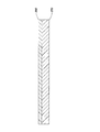
一実施形態では、計量チャンバは、細長く管状であるため、流体チップ内で占める空間を効率的に使用することができ、流体チップ自体も小型になる。別の実施形態では、複数の屈曲部がある蛇行する経路に沿って管状構造を形成することができ、さらに空間効率が上がる。本考案はこれに限定されず、蛇行経路は数回180度に曲がってもよく、または何か他の経路に沿っていてもよい。複数の屈曲部があることでアスペクト比が大きいチャネルを使用することができ、計量チャンバ内を流れる流体内の気泡の堆積を最小限にできる。 In one embodiment, the metering chamber is elongated and tubular so that space occupied within the fluid chip can be used efficiently and the fluid chip itself is also small. In another embodiment, the tubular structure can be formed along a serpentine path with a plurality of bends, further increasing space efficiency. The present invention is not limited to this, and the meandering path may be bent 180 degrees several times, or along some other path. The presence of multiple bends allows the use of channels with a large aspect ratio and minimizes the accumulation of bubbles in the fluid flowing through the metering chamber.
別の実施形態では、計量チャンバは、ふくらみが大きい突起に分割でき、個別の出力量を画定することができる。これらの突起は、矩形、球、または他の任意の適切な形態を含む任意の形状を有することができる。別の実施形態では、計量チャンバは、アスペクト比が小さい大型のチャンバであって、個別の出力量を分配することができる。さらに別の実施形態では、計量チャンバはほぼ平面状であって、2方向に延出する。本考案はこれに限定されず、計量チャンバの他の適切な形態も使用することができる。 In another embodiment, the metering chamber can be divided into large bulges to define individual output quantities. These protrusions can have any shape including a rectangle, a sphere, or any other suitable form. In another embodiment, the metering chamber is a large chamber with a small aspect ratio that can distribute individual output quantities. In yet another embodiment, the metering chamber is substantially planar and extends in two directions. The present invention is not limited to this, and other suitable forms of metering chambers can be used.
別の態様では、流体処理装置は洗浄システムを備える。一実施形態では、計量チャンバおよび充填チャネル全体に高圧でパージ材料(通常は空気および/または水)を流す主パージチャネルに接続された一組のパージチャネルが提供される。一実施形態では、パージ材料は、逆洗浄システム内のパージバルブ制御によって適切なチャネル内を流れる。材料の相互汚染の可能性を最小限にするために、次回の計量分配のために次の流体材料が供給されるまで、パージ材料は計量チャンバおよび充填チャネル内を逆方向に流れる。別の実施形態では、材料の相互汚染を最小限にするために、次回の計量分配のために次の流体材料が供給されるまで、計量チャンバおよび充填チャネル内にパージ材料を数回流すことができる。実際、次回の計量分配のために次の流体材料が供給されるまで、計量チャンバ内にパージ材料を逆方向に流す処理とパージ材料を数回流す処理との組合せを実行することも可能である。充填と逆方向の洗浄のこのプロセスを流体材料の各々に対して繰り返し実行することができる。 In another aspect, the fluid treatment device comprises a cleaning system. In one embodiment, a set of purge channels are provided that are connected to a main purge channel that flows purge material (usually air and / or water) at high pressure across the metering chamber and fill channel. In one embodiment, the purge material flows through the appropriate channel by a purge valve control in the backwash system. In order to minimize the possibility of cross-contamination of material, the purge material flows backward through the metering chamber and fill channel until the next fluid material is supplied for the next metering dispense. In another embodiment, the purge material may be flowed several times through the metering chamber and fill channel until the next fluid material is supplied for the next metering to minimize material cross-contamination. it can. In fact, it is also possible to perform a combination of a process of flowing the purge material in the metering chamber in the reverse direction and a process of flowing the purge material several times until the next fluid material is supplied for the next dispensing. . This process of filling and reverse cleaning can be repeated for each of the fluid materials.
逆方向の洗浄に使用するパージ材料は、空気および/または水に限らずさまざまな材料の1つまたは組合せを含むことができる。例えば、計量分配する材料が空気および/または水で適切に洗浄されない時には、アセトン、エタノール、窒素、二酸化炭素、または他の適切な気体または流体材料あるいはこれらの組合せなどの異なるタイプのパージ材料を使用することができる。 The purge material used for reverse cleaning can include one or a combination of various materials, not limited to air and / or water. For example, use different types of purge materials such as acetone, ethanol, nitrogen, carbon dioxide, or other suitable gas or fluid material or combinations thereof when the material being dispensed is not properly cleaned with air and / or water can do.
例えば、一実施形態では、圧力入口からパージ材料および残余の選択した材料を所望のチャンバを通して送り込むことができることを理解されたい。別の実施形態では、真空が圧力勾配をもたらすことができ、パージ材料および残余の選択した材料を異なるチャンバに効果的に引き込むことができる。別の実施形態では、圧力上昇および真空の組合せを含む動的な圧力変化によって残余の流体材料をさらに撹拌して洗浄の効率を高めることができる。本考案は、逆方向洗浄に限定されず、本考案では順方向洗浄も適切な洗浄方法であることを理解されたい。また、本考案はこれに限定されず、計量分配の間の洗浄は実行しなくてもよいことを理解されたい。 For example, in one embodiment, it should be understood that the purge material and the remaining selected material can be pumped through the desired chamber from the pressure inlet. In another embodiment, a vacuum can provide a pressure gradient, and the purge material and the remaining selected material can be effectively drawn into different chambers. In another embodiment, the remaining fluid material can be further agitated to increase cleaning efficiency by dynamic pressure changes including a combination of pressure rise and vacuum. It should be understood that the present invention is not limited to reverse cleaning, and forward cleaning is also a suitable cleaning method in the present invention. Also, it should be understood that the present invention is not limited to this, and cleaning during dispensing may not be performed.
上記のように、各計量チャンバは、計量チャンバからの指定の個別の出力量に各々対応するいくつかの出口バルブを含むことができる。一態様では、計量チャンバからの各々の所望の出力量に対応するバルブは流体チップ内のすべての計量チャンバに対して一緒に共通に制御される。こうして、特定の出力量を単一の流体処理装置のすべての計量チャンバから計量分配する時には、所望の出力量に対応するすべてのバルブを一緒に制御することができる。その結果、全体の計量分配効率を損なうことなく制御の複雑さをさらに簡単にすることができる。 As noted above, each metering chamber can include a number of outlet valves, each corresponding to a specified individual output quantity from the metering chamber. In one aspect, the valves corresponding to each desired output amount from the metering chamber are commonly controlled together for all metering chambers in the fluidic chip. Thus, when dispensing a particular output quantity from all metering chambers of a single fluid treatment device, all valves corresponding to the desired output quantity can be controlled together. As a result, control complexity can be further simplified without sacrificing overall dispensing efficiency.
本考案は、個別の出力量に基づくバルブ制御だけに限定されないことを理解されたい。したがって、一実施形態では、1つの特定の個別の出力量に対する1つの特定の計量チャンバに対応する各バルブは、別々に個別に制御することができる。別の実施形態では、計量チャンバのサブグループに対応するバルブの第1の部分は、各バルブの対応する個別の出力量に従って一緒に制御することができる。同様に、計量チャンバの同じサブグループに対応するバルブの第2の部分はバルブの第1の部分とは別個に一緒に制御することができる。同様に、計量チャンバの他のサブグループに対応するバルブの別の組は適宜一緒に制御することができる。実際、流体処理装置内の任意の数の計量チャンバに対応するバルブの数を制限するものではないということを理解されたい。本考案は、共通のまたは個別の任意のタイプのバルブ制御に対して設計することができるのは確かであるが、既存システムの範囲内であることが適切に望ましい。 It should be understood that the present invention is not limited to valve control based on individual output quantities. Thus, in one embodiment, each valve corresponding to one particular metering chamber for one particular individual output quantity can be controlled separately. In another embodiment, the first portion of the valves corresponding to the sub-group of metering chambers can be controlled together according to the corresponding individual output amount of each valve. Similarly, the second portion of the valve corresponding to the same subgroup of metering chambers can be controlled together separately from the first portion of the valve. Similarly, different sets of valves corresponding to other subgroups of metering chambers can be controlled together as appropriate. In fact, it should be understood that the number of valves corresponding to any number of metering chambers in a fluid treatment device is not limited. While the present invention can certainly be designed for any common or individual type of valve control, it is suitably desirable to be within the scope of existing systems.
別の態様はバルブの構造に関する。いくつかの実施形態では、バルブは、その性能、特に機械的柔軟性および構造の完全性に関する性能を最大限にする物理的特徴を含む。一実施形態では、マルチレベルバルブ構造が使用される。マルチレベルバルブは、追加の表面領域を提供するバルブ周囲の追加の基部構造を備えた堅くて同時に伸縮する材料または構造からなる。この結果、気密シールの効率が増す。マルチレベルバルブには上方に延びるリップも含まれ、後述するように圧縮面が増加している。 Another aspect relates to the structure of the valve. In some embodiments, the valve includes physical features that maximize its performance, particularly with respect to mechanical flexibility and structural integrity. In one embodiment, a multi-level valve structure is used. A multi-level valve consists of a rigid and co-stretchable material or structure with an additional base structure around the valve that provides additional surface area. As a result, the efficiency of the hermetic seal is increased. The multi-level valve also includes an upwardly extending lip, which increases the compression surface as will be described later.
一実施形態では、バルブは、バルブ膜に対して空気を吹き付ける(バルブを閉じる)かまたはバルブ膜に圧力を印加しない(バルブを開ける)ための圧力入口を通して制御される。場合によっては、真空を印加して流体材料の流れをよくする。別の実施形態では、バルブ膜への入口からの加圧によってバルブが開き、入口から加圧しない(または真空を印加する)ことでバルブを閉じるようにバルブを設計することができることを理解されたい。 In one embodiment, the valve is controlled through a pressure inlet to blow air against the valve membrane (close the valve) or not apply pressure to the valve membrane (open the valve). In some cases, a vacuum is applied to improve fluid material flow. In another embodiment, it should be understood that the valve can be designed to open by pressurization from the inlet to the valve membrane and close the valve by not applying pressure (or applying a vacuum) from the inlet. .
バルブは、さまざまな適切な材料から形成することができることを理解されたい。それ故、一実施形態では、バルブは、シリコーン、ゴム、ポリエチレン、ポリジメチルシロキサンなどのエラストマー材料、または任意の適切なポリマー等価物あるいはこれらの適切な組合せから構成することができる。別の実施形態では、バルブは、電気的または機械的な性質を問わず、任意の適切な配置構成で作動させられる金属またはセラミックなどの適切な堅い材料からなっていてもよい。堅い材料を使用する場合、開閉可能な蝶番またはゲートウェイを使用することができる。 It should be understood that the valve can be formed from a variety of suitable materials. Thus, in one embodiment, the valve can be composed of an elastomeric material such as silicone, rubber, polyethylene, polydimethylsiloxane, or any suitable polymer equivalent or a suitable combination thereof. In another embodiment, the valve may be made of a suitable rigid material, such as a metal or ceramic that can be operated in any suitable arrangement, regardless of electrical or mechanical properties. When using rigid materials, an openable hinge or gateway can be used.
別の態様では、バルブのクラスタを単一のエラストマー片に一緒に成形することができる。一実施形態では、互いに隣接する計量チャンバから計量分配する個別の出力量の部分的な制御が提供される。この場合、隣接する計量チャンバを部分的に制御するバルブのクラスタによって全体の空間が節約され、製造が容易になる。 In another aspect, the cluster of valves can be molded together into a single piece of elastomer. In one embodiment, partial control of individual output quantities dispensed from adjacent metering chambers is provided. In this case, a cluster of valves that partially control adjacent metering chambers saves overall space and facilitates manufacturing.
バルブのクラスタ化については、いくつかの代替実施形態が存在することを理解されたい。一実施形態では、個別の計量チャンバのすべてのバルブ領域を制御するためにバルブのクラスタを使用することができる。別の実施形態では、バルブのクラスタは、少なくとも1つの計量チャンバのバルブ領域の一部としか連通することができない。別の実施形態では、バルブのクラスタは、少なくとも2つの計量チャンバと部分的に連通することができる。別の実施形態では、バルブのクラスタは、少なくとも3つの別々の計量チャンバと部分的に連通することができる。別の実施形態では、バルブのクラスタは、少なくとも4つの別々の計量チャンバと部分的に連通することができる。実際、本考案はこれに限定されず、さらに別の実施形態では、バルブのクラスタは、1つの計量チャンバとだけ部分的に連通することができる。同様に、バルブのクラスタは、流体チップ内のすべての計量チャンバと完全に連通することができる。バルブのクラスタが計量チャンバ内の領域を部分的に(または完全に)制御する方法の設計には制限がないということを理解されたい。 It should be understood that there are several alternative embodiments for valve clustering. In one embodiment, a cluster of valves can be used to control all valve regions of individual metering chambers. In another embodiment, the cluster of valves can only communicate with a portion of the valve area of at least one metering chamber. In another embodiment, the cluster of valves can be in partial communication with at least two metering chambers. In another embodiment, the cluster of valves can be in partial communication with at least three separate metering chambers. In another embodiment, the cluster of valves can be in partial communication with at least four separate metering chambers. Indeed, the present invention is not limited to this, and in yet another embodiment, the cluster of valves can be in partial communication with only one metering chamber. Similarly, a cluster of valves can be in full communication with all metering chambers in the fluid chip. It should be understood that there is no limit to the design of how the cluster of valves partially (or fully) control the area within the metering chamber.
本考案はこれに限定されず、上記態様は、任意の適切な組合せで使用することができることを理解されたい。また、上記態様の任意のまたは全部の態様を流体処理システムで使用してマイクロプレートのウェルへの流体の計量分配を実行することができる。しかし、態様は、任意の流体計量分配システムで使用することができるため、本考案はこれに限定されない。添付の図面を参照して、本考案の種々の態様および実施形態について詳述する。しかし、本考案は図示の態様および実施形態に限定されない。 It should be understood that the invention is not limited thereto and that the above aspects can be used in any suitable combination. Also, any or all of the above aspects can be used in a fluid processing system to perform fluid dispensing to the wells of a microplate. However, the present invention is not limited to this, as the embodiments can be used with any fluid dispensing system. Various aspects and embodiments of the present invention will be described in detail with reference to the accompanying drawings. However, the present invention is not limited to the illustrated aspects and embodiments.
図を参照すると、流体処理装置10の一実施形態の概略が図1に示されている。流体処理装置10は、選択した材料を所定の出力量だけ選択したウェルに迅速かつ効率的に計量分配するように構成されている貯留部、チャネル、およびバルブの集まりを含む。図1の概略図に示すように、対応するソース貯留部20a、20b、20c、20d、20e、および20f内にいくつかの異なる材料12が提供され、材料が選択的に供給されてさらに処理される際に通過する材料バルブ22a、22b、22c、22d、22eおよび22fに接続されている。材料は、一度に1つ選択することができ、その後、材料チャネル24に流入する。チャネル24は主充填チャネル26に送られる。一実施形態では、各ソース貯留部に対応する個別の材料チャネルおよび充填チャネルが提供することができる。本考案はこれに限定されず、任意の数のソース貯留部およびそれに対応する材料バルブを使用することができることは明らかである。
Referring to the drawings, an outline of one embodiment of a
図1に概略を示す実施形態に戻って、主充填チャネル26は、計量チャンバ30a、30b、30c、30d、および30eに接続され、そこで流れは充填バルブ28a、28b、28c、28d、および28eを介して個別に制御され、各々の選択した計量チャンバを所望の材料で完全に充填する。
Returning to the embodiment schematically illustrated in FIG. 1, the
他の実施形態では、任意の数の計量チャンバと各計量チャンバに対応する充填バルブがあってよく、また、本明細書に記載する数は本考案をいかなる方法でも限定しないことを理解されたい。一実施形態では、少なくとも1つの計量チャンバが存在する。別の実施形態では、少なくとも2つの計量チャンバが存在する。別の実施形態では、少なくとも3つの計量チャンバが存在する。別の実施形態では、少なくとも4つの計量チャンバが存在する。別の実施形態では、少なくとも5つの計量チャンバが存在する。別の実施形態では、少なくとも12個の計量チャンバが存在する。別の実施形態では、少なくとも96個の計量チャンバが存在する。一実施形態では、計量チャンバの数は流体が流体処理装置から計量分配されるマイクロプレートで使用されるウェルの数に対応する。 In other embodiments, there may be any number of metering chambers and a fill valve corresponding to each metering chamber, and it should be understood that the numbers set forth herein do not limit the invention in any way. In one embodiment, there is at least one metering chamber. In another embodiment, there are at least two metering chambers. In another embodiment, there are at least three metering chambers. In another embodiment, there are at least four metering chambers. In another embodiment, there are at least five metering chambers. In another embodiment, there are at least 12 metering chambers. In another embodiment, there are at least 96 metering chambers. In one embodiment, the number of metering chambers corresponds to the number of wells used in the microplate in which fluid is dispensed from the fluid processing device.
また、各計量チャンバは、複数の小容量出力バルブ32a、32b、32c、32d、および32e、複数の中容量出力バルブ34a、34b、34c、34d、および34e、ならびに複数の大容量出力バルブ36a、36b、36c、36d、および36eを備える。これらのバルブは、それぞれの計量チャンバから計量分配ノズル38a、38b、38c、38d、および38eを通して対応する出力ウェル40a、40b、40c、40d、および40eに計量分配される所望の出力量を設定するために使用される。計量分配される特定の量は計量チャンバ内でどの出力バルブを作動させるかによって異なる。別の実施形態では、各計量チャンバが備える出力バルブの数は任意でよく、それぞれの計量チャンバから任意の個数の所望の出力量を計量分配することができることを理解されたい。
Each metering chamber also includes a plurality of small
選択してその後計量分配できる材料の数には制限がないことを理解されたい。したがって、一実施形態では、選択して計量分配できる少なくとも1つの材料がある。別の実施形態では、選択して計量分配できる少なくとも2つの材料がある。別の実施形態では、選択して計量分配できる少なくとも3つの材料がある。別の実施形態では、選択して計量分配できる少なくとも4つの材料がある。別の実施形態では、選択して計量分配できる少なくとも5つの材料がある。別の実施形態では、選択して計量分配できる少なくとも6つの材料がある。別の実施形態では、選択して計量分配できる少なくとも25個の材料がある。別の実施形態では、選択して計量分配できる少なくとも96個の材料がある。なお、選択して計量分配できる材料は任意の適切な形態、相またはこれらの組合せをとることができることを理解されたい。例えば、材料は、液相、気相、または固相でよい。さらに、材料は、上記の相の1つの組合せ、例えば、エマルジョン、不混和性の混合物、または溶解状態でよい。 It should be understood that there is no limit to the number of materials that can be selected and subsequently dispensed. Thus, in one embodiment, there is at least one material that can be selected and dispensed. In another embodiment, there are at least two materials that can be selected and dispensed. In another embodiment, there are at least three materials that can be selected and dispensed. In another embodiment, there are at least four materials that can be selected and dispensed. In another embodiment, there are at least five materials that can be selected and dispensed. In another embodiment, there are at least six materials that can be selected and dispensed. In another embodiment, there are at least 25 materials that can be selected and dispensed. In another embodiment, there are at least 96 materials that can be selectively dispensed. It should be understood that the material that can be selected and dispensed can take any suitable form, phase, or combination thereof. For example, the material can be a liquid phase, a gas phase, or a solid phase. Furthermore, the material may be in one combination of the above phases, for example, an emulsion, an immiscible mixture, or a dissolved state.
材料が選択されウェルに出力される方法は、また、いくつかの異なる方法で実行することができることを理解されたい。一実施形態では、材料が計量チャンバ内に堆積される際に通過する少なくとも1つの個別の充填チャネルが提供される。別の実施形態では、材料が計量チャンバ内に堆積される際に通過する少なくとも2つの個別の充填チャネルが提供される。別の実施形態では、材料が計量チャンバ内に堆積される際に通過する少なくとも3つの個別の充填チャネルが提供される。別の実施形態では、材料が計量チャンバ内に堆積される際に通過する少なくとも4つの個別の充填チャネルが提供される。別の実施形態では、材料が計量チャンバ内に堆積される際に通過する少なくとも5つの個別の充填チャネルが提供される。別の実施形態では、材料が計量チャンバ内に堆積される際に通過する少なくとも12個の個別の充填チャネルが提供される。別の実施形態では、材料が計量チャンバ内に堆積される際に通過する少なくとも96個の個別の充填チャネルが提供される。一般に、材料、貯留部、チャネルおよびバルブの数は所望するいかなる数にも合わせて増減することができることを理解されたい。 It should be understood that the method by which material is selected and output to the well can also be performed in a number of different ways. In one embodiment, at least one individual filling channel is provided through which material passes as it is deposited in the metering chamber. In another embodiment, at least two separate fill channels are provided through which material passes as it is deposited in the metering chamber. In another embodiment, at least three separate fill channels are provided through which material passes as it is deposited in the metering chamber. In another embodiment, at least four separate fill channels are provided through which material passes as it is deposited in the metering chamber. In another embodiment, at least five individual filling channels are provided through which material passes as it is deposited in the metering chamber. In another embodiment, at least 12 individual fill channels are provided through which material passes as it is deposited in the metering chamber. In another embodiment, at least 96 individual fill channels are provided through which material passes as it is deposited in the metering chamber. In general, it should be understood that the number of materials, reservoirs, channels, and valves can be increased or decreased to any desired number.
さらに、計量チャンバの数は、出力ウェルの数と一致しなくてもよい。計量チャンバの複数の出力ウェルへの計量分配は、例えば、計量チャンバノズルが計量分配でき、次の計量分配にあたって、選択したウェルに移動できる移動性をシステムに取り込むことで達成することができる。同様に、システムは、計量チャンバから選択した出力ウェルへの計量分配を可能とし、次の計量分配のために選択した出力ノズルの下に他の出力ウェルを移動させることができる。一実施形態では、1つの計量チャンバが少なくとも2つの出力ウェルに計量分配することができる。別の実施形態では、1つの計量チャンバが少なくとも3つの出力ウェルに計量分配することができる。別の実施形態では、1つの計量チャンバが少なくとも96個の出力ウェルに計量分配することができる。 Further, the number of metering chambers may not match the number of output wells. Dispensing to multiple output wells of the metering chamber can be accomplished, for example, by incorporating into the system mobility that allows the metering chamber nozzle to dispense and move to the selected well during the next metering dispense. Similarly, the system allows dispensing from a metering chamber to a selected output well and can move other output wells below the selected output nozzle for the next dispensing. In one embodiment, one metering chamber can dispense to at least two output wells. In another embodiment, one metering chamber can dispense to at least three output wells. In another embodiment, one metering chamber can dispense to at least 96 output wells.
図2および図3は、流体処理装置10の一実施形態の分解斜視図である。この装置は、5つの主要構成要素、すなわち、マニホールドコレクタ100と、共用制御モジュール150と、材料マニホールド200と、流体が通過するための導管を有する流体チップ300と、6つ、すなわち、400a、400b、400c、400d、400e、および400fが図示されているいくつかの制御モジュールとを含む。流体チップ300、または材料マニホールド200がない同じ構成要素の下方から見た斜視図が図3に示されている。マニホールドコレクタ100は、他の4つの構成要素を装着できるスロットを含む。流体チップ300を装着するそのようなスロット103が示されている。
2 and 3 are exploded perspective views of one embodiment of the
流体の流れは、任意の適切な配置構成を使用して制御することができる。一実施形態では、流体は以下に詳述するようにソレノイド作動バルブで制御される。一実施形態では、流体チップ300上のバルブのさまざまなグループが単一のソレノイド制御ソースからの制御を共用する。これらの共用ソレノイド制御ソースは、マニホールドコレクタ100の下側に取り付けられた共用制御モジュール150上に共に配置されている。一実施形態では、共用制御モジュール150は、共用パージおよび容量出力サイズを制御できる共用バルブソレノイド160を含む。材料マニホールド200は、流体チップ300への材料およびパージ物質を供給し、流体チップ300から廃棄するために、材料貯留部210、パージ空気管212、洗浄水管214、ならびに溢流および廃棄管216を差し込める場所のための接続を含む。流体チップ300は、材料およびパージ物質の流体の流れ、材料の計量、および最終的な計量分配が行われる計量アセンブリを含む。マニホールドコレクタ100の反対側に取り付けられた制御モジュール400a、400b、400c、400d、400e、および400fは、流体チップ300内の異なるバルブの制御を行うことができるソレノイドを含む。図2および図3に示す各制御モジュール400内には、流体チップ300内のそれぞれの計量チャンバへの材料の充填を制御する個別の充填ソレノイド402が16個配置されている。制御モジュールのこの配置構成で、計量チャンバごとに96個の個別に制御される充填バルブが可能になる。追加の制御モジュールを使用することができ、および/または各制御モジュール上に上記より多くの、または少ないソレノイドバルブを使用することができることを理解されたい。
Fluid flow can be controlled using any suitable arrangement. In one embodiment, the fluid is controlled by a solenoid actuated valve as detailed below. In one embodiment, various groups of valves on the
共用制御マニホールド150は、マニホールドコレクタ100に隣接して配置され、各々の選択可能な個別の出力量の計量分配とパージ洗浄とを共通に制御する共用バルブソレノイド160を含む。一実施形態では、小出力量は1つのソレノイドバルブによって制御される。中出力量は、別の1つのソレノイドバルブによって制御される。大出力量は、さらに別の1つのソレノイドバルブによって制御される。パージ洗浄は、1つのソレノイドバルブによって制御される。個別の出力量計量分配の各々とパージとは共通に制御しなくてもよいことを理解されたい。実際、本考案は、流体チップ300全体の各バルブが別々のバルブによって個別に制御することができるように設計可能である。
The
また、共用制御マニホールド150は、充填速度制御向上のための図14(b)に示す溢流バルブ650への圧力を制御するように機能する溢流圧力供給口170を備える。このように、溢流バルブ圧力が他のバルブとは別に制御することができるため、上記圧力制御によって過剰な材料廃棄物が最小限にされる。共用マニホールド接続180によって、共用制御マニホールド150はマニホールドコレクタ100と連通する。マニホールドコレクタ100は、流体チップ300上の共用バルブと連通する共用制御マニホールド150上のバルブ間の導管としての働きをする共用バルブ接続190をさらに含む。
Further, the
図4は、流体処理装置10の別の実施形態の図である。この装置は、3つの主要構成要素、すなわち、材料マニホールド200、流体チップ300、および制御モジュール400を含む。この実施形態では、共用制御モジュールは存在しない。材料マニホールド200は、流体チップ300への材料およびパージ物質を供給し、流体チップ300から廃棄するために、材料貯留部210、空気および水供給管213、廃棄物容器225、ならびに溢流容器215を差し込める場所のための接続を含む。流体チップ300は、材料およびパージ物質の流体の流れ、材料の計量、および最終的な計量分配が行われる計量アセンブリを含む。制御モジュール400は、流体チップ300内のさまざまなバルブの制御を行うことができるソレノイドバルブを含む。制御モジュール400内には、流体チップ300内への材料の充填を制御する個別の充填ソレノイド402が配置されている。
FIG. 4 is a diagram of another embodiment of the
流体処理装置は、本明細書の実施形態に限定されないことを理解されたい。例えば、一実施形態では、材料供給、流体処理装置の計量および計量分配、ならびに制御供給の態様は、すべて1つの汎用マニホールド上に統合することができる。別の実施形態では、材料の供給および流体の計量は1つの共通の基板上に統合することができ、制御供給はその上に装着することができる。こうして、材料およびパージ物質の供給、計量、および計量分配のプロセスは1つの多目的基板上で実行され、プロセスの実行方法を制御する構成要素は装置全体の別の領域に配置される。別の実施形態では、材料の供給および制御の供給は1つの基板上に統合することができ、流体の計量はその上に装着することができる。これに関して、制御を可能にする材料およびパージ物質の供給ならびに態様は、1つの共通領域に提供され、流体の計量と計量分配は装置の別の部分で実行される。別の実施形態では、流体の計量と制御の供給は、1つの別の基板上に統合することができ、材料の供給はその上に装着することができる。こうして、制御と流体の計量および計量分配とを可能にする態様はその基板上で共に実施することができ、材料およびパージ物質は、装置全体の別の領域から供給される。別の実施形態では、材料供給、制御手段、ならびに計量および計量分配の構造態様は混合することができる。実際、装置に組み込むことができ、本考案の一部としてすべて理解することができるいくつかの設計実施形態があることを理解されたい。 It should be understood that the fluid treatment device is not limited to the embodiments herein. For example, in one embodiment, the material supply, metering and dispensing of the fluid treatment device, and control supply aspects can all be integrated onto a single universal manifold. In another embodiment, the material supply and fluid metering can be integrated onto one common substrate, and the control supply can be mounted thereon. Thus, the material and purge substance supply, metering, and dispensing processes are performed on one multipurpose substrate, and the components that control how the process is performed are located in separate areas of the overall apparatus. In another embodiment, the material supply and the control supply can be integrated on one substrate and the fluid metering can be mounted on it. In this regard, the supply and aspects of the material and purge substance that allow control are provided in one common area, and fluid metering and dispensing is performed in another part of the apparatus. In another embodiment, the fluid metering and control supply can be integrated onto one separate substrate and the material supply can be mounted thereon. Thus, aspects that allow control and fluid metering and metering can be performed together on the substrate, with material and purge material being supplied from separate areas of the entire apparatus. In another embodiment, the material supply, control means, and metering and dispensing structural aspects can be mixed. In fact, it should be understood that there are several design embodiments that can be incorporated into the device and can all be understood as part of the present invention.
一実施形態では、マニホールドコレクタ100は、図3に示す熱可塑性層から構成される。コレクタ厚肉層104は、コレクタ薄肉上部層102とコレクタ薄肉下部層106との間に挟まれている。一実施形態では、層は、ねじで結集されている。別の実施形態では、層は適切な接着材料で結集されている。別の実施形態では、層はヒートシールされている。マニホールドコレクタ100は層状デバイスに限定されず、単一のモノリシック片であってもよいことを理解されたい。実際、別の実施形態では、マニホールドコレクタ100は任意の適切な数の層からも構成することができる。さらに、層の材料は熱可塑性材料に限定されず、いくつかの適切な材料、例えば、金属またはセラミックであってもよい。
In one embodiment, the
一実施形態では、共用制御マニホールド150は、図3に示す熱可塑性層からも構成することができる。共用マニホールド薄肉層152は、共用マニホールド厚肉層154に隣接して配置することができる。一実施形態では、層はねじで結集されている。別の実施形態では、層は適切な接着材料で結集されている。別の実施形態では、層はヒートシールされている。マニホールドコレクタ100は、層状デバイスに限定されず、単一のモノリシック片であってもよいことを理解されたい。実際、別の実施形態では、マニホールドコレクタ100は、任意の適切な数の層からも構成することができる。さらに、層の材料は熱可塑性材料に限定されず、いくつかの適切な材料、例えば、金属またはセラミックであってもよい。
In one embodiment, the shared
図5に最もよく示されているように、材料マニホールド200は流体を流体チップ300まで運び、流体チップ300から廃棄物を搬出するように機能する。一実施形態では、材料マニホールド200は、図5の線3C−3Cに沿った断面図である図7に最もよく示すように、いくつかの層からも構成することができる。材料マニホールド厚肉層250は、適当なチャネルを封止して厚肉層250の適切な補完物の役割を果たすより薄い熱可塑性要素でよい材料マニホールド薄肉層260に取り付けられた圧延チャネルを備えた熱可塑性片であってもよい。一実施形態では、材料マニホールド厚肉層250および薄肉層260は、ねじで結集されている。別の実施形態では、材料マニホールド厚肉層250および薄肉層260は、適切な接着材料で結集されている。別の実施形態では、層はヒートシールされている。材料マニホールド200は層状デバイスに限定されず、単一のモノリシック片であってもよいことを理解されたい。実際、別の実施形態では、材料マニホールド200は、任意の適切な数の層からも構成することができる。さらに、層の材料は熱可塑性材料に限定されず、いくつかの適切な材料、例えば、金属またはセラミックであってもよい。
As best shown in FIG. 5, the
材料ソレノイドバルブ280は、また、図5に示すように、材料マニホールド200上に組み立てられ、流体チップ300への材料の流れおよび流体チップ300からの廃棄物の流れの制御に寄与する。ソレノイドバルブ280は、開いた状態または閉じた状態であってよい。インスタント管継手290も配置することができ、管および外部流体貯留部から材料マニホールド200内のチャネルに接続することができる。一実施形態では、インスタント管継手290は、材料マニホールド200にねじ込むように構成することができる。別の実施形態では、接着剤を使用してインスタント管継手290を材料マニホールド200内に適切に配置して固定することができる。別の実施形態では、インスタント管継手290を材料マニホールド200内に適切に配置してヒートシールすることができる。材料マニホールド200内には、材料貯留部210に接続された材料充填チャネル220があり、適当なソレノイドバルブ280が作動して開いた状態の時にそれぞれの材料貯留部210からの選択された材料が材料充填チャネル220、次いで主充填チャネル222に流れ込み、流れが流体チップ300内の計量チャンバ510に到達する(図13を参照)。この場合、各々選択されて流体チップ300内の計量チャンバを充填することができる25個の異なる材料貯留部210が存在する。任意の数の材料を材料マニホールド200に組み込むことができることを理解されたい。
The
一実施形態では、材料マニホールド200上に溢流出口224が提供される。計量チャンバを通過する余分な材料は、溢流出口224を抜けて図5に示す別の溢流および廃棄物容器216に流れ込む。別の実施形態では、流体チップ300が洗浄されると、廃棄物は、同じ主充填チャネル222のラインを流体チップ300から廃棄物チャネル226へ逆方向に流れ、廃棄物バルブ227を通って、最終的に溢流および廃棄物容器216に流れ込む。
In one embodiment, an
一実施形態では、パージチャネル228が、材料マニホールド200内に提供される。パージチャネル228は、加圧空気および/または水あるいは他の適切な流体を供給して装置に関連する別のチャネルに材料を押し出す。材料マニホールド200上には、三方ソレノイドバルブ230を配置することができ、パージ物質をパージ空気管212と洗浄水管214とから供給される空気と水との間で切り替える。
In one embodiment, a
材料マニホールド200の別の実施形態を図6に示す。上記実施形態と同様、材料マニホールド200は、適当に封止された圧延チャネルを備えたいくつかの熱可塑性層から構成される。一実施形態では、層はねじで結集されている。別の実施形態では、層は適切な接着材料で結集されている。別の実施形態では、層はヒートシールされている。材料マニホールド200は、層状デバイスに限定されず、単一のモノリシック片であってもよい。実際、別の実施形態では、材料マニホールド200は、任意の適切な数の層からも構成することができる。さらに、層の材料は熱可塑性材料に限定されず、いくつかの適切な材料、例えば、金属またはセラミックであってもよい。
Another embodiment of a
上記実施形態と同様、材料ソレノイドバルブ280も材料マニホールド200上に組み立てられ、流体チップ300への材料の流れおよび流体チップ300からの廃棄物の流れの制御に寄与する。材料マニホールド200上に組み込まれたソレノイドバルブ280は、マニホールド200内の対応する材料貯留部210に接続された材料充填チャネル220と連通する開いた状態または閉じた状態である。一実施形態では、適当なソレノイドバルブ280が開くと、それぞれの材料貯留部210からの選択された材料が、材料充填チャネル220、次いで主充填チャネル222に流れ込み、流れが流体チップ300内の計量チャンバ510に到達する(図13を参照)。この場合、各々選択されて流体チップ300内の計量チャンバを充填することができる3つの異なる材料貯留部210が存在する。任意の数の材料を材料マニホールド200に組み込むことができることを理解されたい。
Similar to the above embodiment, the
この実施形態では、材料マニホールドは、また、溢流出口224を含む。計量チャンバを通過する余分な材料は、溢流出口224を抜けて別の溢流容器215に流れ込む。上記実施形態と同様、流体チップ300が洗浄されると、廃棄物は主充填チャネル222のラインを流体チップ300から廃棄物チャネル226へ逆方向に流れ、廃棄物バルブ227を通って、最終的に溢流容器225に流れ込む。この実施形態と上記実施形態との主な相違点は、図6に示すように、溢流および廃棄物材料は、この実施形態では別々の容器215および225に分散されるが、溢流および廃棄物材料は図5に示す共通の容器216に流れ込むという点である。
In this embodiment, the material manifold also includes an
この実施形態では、パージチャネル228は、加圧空気および/または水(または他の適切な流体)を供給して、装置に関連する別のチャネルに材料を押し出す。三方切り替えが可能な別のソレノイドバルブを使用して、パージ物質を空気と水との間で切り替えることができる。
In this embodiment, the
本考案は、これに関してこの実施形態に限定されないことを理解されたい。例えば、別の実施形態では、流体チップ300から逆流する廃棄物は主充填チャネル222を通らず別のラインを通って逆流する。別の実施形態では、装置の残りの部分からの別の洗浄ラインが主充填チャネル222に接続されている。別の実施形態では、溢流出口224は、廃棄物チャネル226に接続していてもよい。材料およびパージ物質を供給するチャネルと溢流および廃棄物材料を外に運ぶチャネルは任意の適切な方法で流体チップ300と連通することができる。
It should be understood that the present invention is not limited to this embodiment in this regard. For example, in another embodiment, waste flowing back from the
上記のように、図2および図3に示すいくつかの制御モジュール400は、通常、圧力管理によって装置10内のさまざまなバルブを作動させる働きをする。制御モジュール400の一実施形態では、制御モジュール厚肉層410は、制御モジュール薄肉層420に結合されている。制御モジュール厚肉層410は、厚肉層420の適切な補完物として機能するより薄い熱可塑性材料でよい制御モジュール薄肉層420に取り付けられた熱可塑性片でよい。一実施形態では、制御モジュール厚肉層410および薄肉層420は、ねじで結集されている。別の実施形態では、制御モジュール厚肉層410および薄肉層420は、適切な接着材料で結集されている。別の実施形態では、制御モジュール厚肉層410および薄肉層420は、ヒートシールされている。制御モジュール400は、層状デバイスに限定されず、単一のモノリシック片であってもよい。実際、別の実施形態では、制御モジュール400は、任意の適切な数の層からも構成することができる。さらに、層の材料は熱可塑性材料に限定されず、いくつかの適切な材料、例えば、金属またはセラミックであってもよい。
As described above,
図8には、1つの制御モジュール400が示されている。制御モジュール400は、マニホールドコレクタ100、次に、流体チップ300に向かう制御チャネル422に接続する出口421を含むことができる。制御チャネル422の各々は、少なくとも1つの充填バルブ640などの図14(b)に示すバルブと最終的に連通する。
FIG. 8 shows one
上記のように、図2および図3の実施形態では、装置は、コレクタマニホールド100と、共用制御マニホールド150とを含む。図9は、マニホールドコレクタ100および共用制御マニホールド150の実施形態を示す。マニホールドコレクタ100は、隣接する制御モジュール400へ圧力を分配する圧力供給入口110を含む。材料チャネル120は、材料マニホールド200から流体チップ300へ材料を供給する導管としての働きをする。コレクタ制御チャネル130は、また、マニホールドコレクタ100内を通過し、制御モジュール400から流体チップ300に至る制御ラインの導管としての働きをする。
As described above, in the embodiment of FIGS. 2 and 3, the apparatus includes a
上記のように、図8に示す流体チップ300にルーティングされた制御モジュール400上の制御ソレノイドバルブ470の開閉によって空気圧が制御される。制御モジュール400の一実施形態では、第1のバルブ入力口440は、制御圧力を供給する。制御圧力は20〜30PSIの範囲にあり、一実施形態では、約25PSIである。制御モジュール400の別の実施形態では、第2のバルブ入力口442は、開いて大気圧を受ける。別の実施形態では、第2のバルブ入力口442は、真空ソースと連通する。バルブ出口444は、対応する制御チャネル422を第1のバルブ入力口440または第2のバルブ入力口442に接続することができる。
As described above, the air pressure is controlled by opening and closing the
一実施形態では、制御圧力供給口460は、マニホールドコレクタ100からの外部で生成され調整された圧力をモジュールに接続する。制御モジュール400は、他の方法で設計することができることを理解されたい。例えば、少なくとも2つの圧力供給口を備えるように、制御モジュール400を設計することができる。別の実施形態では、各バルブは、それぞれの圧力供給口に対応することができる。実際、本考案はこれに限定されるものではない。
In one embodiment, the
一実施形態では、バルブを制御モジュール400に装着するのを助けるためにねじ穴450が提供される。別の実施形態では、バルブを制御モジュール400に装着するのを助けるために接着剤が提供される。
In one embodiment, a threaded
本考案の別の実施形態では、図10に示す1つの制御モジュール400が、装置10内の共用制御バルブを含むすべての制御バルブを作動させる働きをする。この実施形態では、制御モジュール400は、上記モジュールと同様に製造され、同様に記述される特定の実施形態に限定されない。制御モジュール400は、流体チップ300に直接ルーティングされる制御チャネル422を接続する出口421を含むことができる。過剰な材料廃棄物を最小限にするために、他のバルブとは別に溢流バルブ圧力を制御することもできる。一実施形態では、モジュール溢流圧力供給口462は、図14(b)に示す溢流バルブ650への圧力を制御して、充填速度制御を向上させることができる。この点に関し、溢流バルブ以外のすべてのバルブは、同じ制御圧力を受ける。制御圧力供給口460は、外部で生成され調整された圧力をモジュールに直接接続する。この実施形態と図8および図9に示す実施形態との主な相違点は、この実施形態が流体チップ(すなわち、パージおよびさまざまなサイズの出口量)、溢流圧力供給口、および制御圧力供給口上で共用されるソレノイドバルブを直接モジュール上に組み込んでいる点である。図8および図9に示す実施形態では、上記特徴は、装置全体の他の部分、すなわち、マニホールドコレクタ100および共用制御モジュール150にある。制御モジュール400は、他の方法でも設計することができることを理解されたい。例えば、少なくとも2つの圧力供給口を備えるように制御モジュール400を設計することができる。別の実施形態では、各バルブは、それぞれの圧力供給口に対応することができる。実際、本考案は、これに限定されるものではない。
In another embodiment of the present invention, one
また、別の実施形態では、制御チャネル422が図14(b)に示す他のバルブセット、例えば、特定のサイズの容量の出力バルブ、パージバルブ660、または溢流バルブ650と連通することができる。いくつかの実施形態では、制御チャネル422の各々が、流体チップ300上の異なる別個のバルブを独立して制御することができるように制御モジュール400を設計することができることを理解されたい。別の実施形態では、制御チャネル422の各々が、流体チップ300上のすべてのバルブを共通に制御することができるように制御モジュール400を設計することができる。一実施形態では、流体チップ300上の充填バルブ640の各々を別個に独立して制御するように制御チャネル422を設計することができる。別の実施形態では、1つの特定の別個の出力量に共通に対応する流体チップ300上のすべてのバルブを制御するように制御チャネル422を設計することができる。実際、本明細書に記載する実施形態が限定的でなく、制御チャネル422は、適宜流体チップ300上の所望のバルブ制御の組合せで設計することができることを理解されたい。
In another embodiment, the
上記実施形態ではバルブは圧力の印加によって作動するが、本考案はこれに限定されない。それ故、別の実施形態では、バルブは電気式切り替え手段によって作動する。別の実施形態では、バルブは、機械式切り替えによって作動する。 In the above embodiment, the valve operates by applying pressure, but the present invention is not limited to this. Therefore, in another embodiment, the valve is actuated by electrical switching means. In another embodiment, the valve is actuated by mechanical switching.
上記のように、図11の分解図に示すように、1つまたは複数の計量アセンブリが流体チップ300に組み込まれている。流体チップ300は、指定の材料を計測して指定の出力ウェルに計量分配する。一実施形態では、流体チップ300は、2つの主要層、すなわち、制御層310と、流体層350とから構成される。制御層310は、制御薄肉上部層312、制御厚肉層314、および制御薄肉下部層316から構成される。一実施形態では、制御薄肉上部層312は、制御モジュール400インタフェースとしての働きをする制御穴313を有することができる。制御薄肉上部層312の一部は、制御厚肉層314の上側にある制御チャネル330を適当に封止する。こうして、制御チャネル330は封止され、したがって圧力が好適な方法で適切に分配される。制御チャネル330は、制御厚肉層314に適切にエッチングすることができる。本考案はこれに限定されず、チャネルを層314内に製造する他の適切な技法も使用することができる。例えば、チャネルを層内に圧延または成形することができる。制御薄肉下部層316は、また、制御チャネル330および連通するバルブのための制御アクセス穴318を含むことができる。流体チップ300および他の層状モジュールは、層状デバイスに限定されず、単一のモノリシック片でよく、成形またはスレテオリソグラフィ技法などの適切な技法で形成することができる。実際、別の実施形態では、流体チップ300は、任意の適切な数の層で構成することができる。
As described above, one or more metering assemblies are incorporated into the
流体チップ300の一実施形態では、制御厚肉層310内の層は、すべての層を貫通するねじ穴302に入るねじで結集されている。別の実施形態では、制御厚肉層310内の層は、適切な接着材料で結集されている。流体チップ300の別の実施形態では、流体層350内の層は、ねじ穴302に入るねじで結集されている。別の実施形態では、流体層350内の層は、適切な接着材料で結集されている。別の実施形態では、層はヒートシールされている。
In one embodiment of the
図11に示す流体制御チャネル330は、所望の結果による制御された形で流体チップ300内の特定のバルブに圧力を分配し、図8から図10に示す制御モジュール400内の制御チャネル422からの圧力信号を受信する。流体制御チャネル330は制御層310の上部および下部領域の両方に配置することができ、したがって別個のチャネル330は互いに干渉しない。スペーサおよびバルブ層320も流体チップ300内に組み込むことができ、バルブおよびスペーサは、制御層310と流体層350との間に整列して配置される。こうして、スペーサおよびバルブ層320によって、制御および流体層が適切な距離だけ離れてチップ300の最適な機械的機能を果たすことが確保される。
The
一実施形態では、流体層350は、流体薄肉層352と流体厚肉層360とから構成されてもよい。流体薄肉層352は、液体チャネルとバルブとの間のアクセス穴354を通してアクセスでき、流体がバルブにアクセスできる。一実施形態では、流体薄肉層352は、約250μmの厚みである。一実施形態では、あらゆるバルブに対して、制御層310に対応する1つの制御アクセス穴318と流体層350に対応する2つの流体アクセス穴354が提供される。この実施形態では、計量および計量分配は、流体厚肉層360内で実行される。本考案はこれに限定されず、制御層についての上記説明と同様に、流体層350内にチャネルを製造する適切な技法を使用することができる。例えば、層内にチャネルを圧延または成形することができる。
In one embodiment, the
図12は、計量チャンバ510を示す。そのうちいくつかが流体厚肉層360内にあり、別個の部分が、大チャネル部512、中チャネル部514、小チャネル部516、充填チャネル520、溢流チャネル530、およびパージチャネル540に対応する。図12に示す計量チャンバ510の一実施形態は、その内部で材料の分離と計量分配を迅速かつ効率的に実行するいくつかの機能を含む。ここで、材料500は、ソース、計量分配チャンバへと流れる(ソースから最終的な出口である同じノズルまたは領域へ吸引されるのではなく)。計量チャンバ512は、蛇行経路をたどり、占有する全空間が与えられればチャンバからより多くの量を計量分配することができる。蛇行するチャンバ構造はまたチャンバ内の材料500内に気泡が形成されるのを防止するのを助ける。さらに、計量チャンバ510の一部を任意の適切な形の形状にして正確な所望の計量分配出力を提供することができる。例えば、図12に示す実施形態では、上面斜視図が、中チャネル部514および小チャネル部516より厚肉の大チャネル部512を示す。大チャネル部の端部領域はテーパしており、隣接するチャネル厚みのスムーズな移行を可能にする。
FIG. 12 shows the
上記のように、計量チャンバ510は、3つのチャネル部、すなわち、大チャネル部512、中チャネル部514および小チャネル部516に分割することができる。各チャネル部について、対応する大容量移送領域513、中容量移送領域515、および小容量移送領域517も組み込むことができる。上記のように、計量チャンバ510は任意の適切な数のチャネル部に分割することができる。一実施形態では、大チャネル部512と中チャネル部514、小チャネル部516を合わせた容量は約1μLから約10μL、中チャネル部514と小チャネル部516とを合わせた容量は約500nLから約1μL、小チャネル部516だけの容量は約50nLから約500nLである。計量チャンバ510は、個別の出力量または出力される実際の量の個数に関して限定されないことを理解されたい。各容量移送領域のチャネル厚みを比較的均一にして正確な計量分配を実行することは、これに限定はされないが、好適であることを理解されたい。
As described above, the
一実施形態では、各計量チャンバ510は、また、充填チャネル520と、特定の計量チャンバ510への充填チャネル500のアクセスを提供する関連する充填移送領域521とを含む。この場合、充填材料は材料マニホールド200で生成され、図5から図7に示す主充填チャネル222から図13に示す共通充填チャネル362に移送され、最終的に充填チャネル520に流入する。充填移送領域521に対応する図14(b)に示す充填バルブ640は、大チャネル部512、中チャネル部514、および小チャネル部516の容量部を含む所望の材料500が選択した計量チャンバ510に流入することができるように作動する。一態様では、単一の充填ラインが、対応する充填チャネル520を通って各計量チャンバ510にルーティングされ、各計量チャンバ510の充填バルブ640は別個に制御される。この点に関して、各計量チャンバ510は、材料マニホールド200からの任意の材料で選択的に充填することができる。
In one embodiment, each
計量チャンバ510が完全に満杯になったら、材料溢流が発生し、溢流チャネル532を通って溢流移送領域530に流れ込む。過度の溢流を防止するために、制限バルブ領域550を作動させて計量チャンバ510への充填速度を低減することができる。一実施形態では、流れの速度を低減するために加圧または任意の適切な手段によって適当に収縮することができる制限管を制限バルブ領域550内に提供することができる。こうして、低減された流れの速度を適宜制御することができる。別の実施形態では、外部加圧または他の刺激がない毛細管構造が制限バルブ領域550内に提供され、外部制御なしで流れの速度を低減することができる。
When the
計量チャンバ510の計量分配または洗浄を望む時には、図14(b)に示すパージバルブ660を作動させることで、パージチャネル540、パージ移送領域542を経て計量チャンバにパージ内容物を流すことができる。所望であれば、充填チャネル520もパージ内容物を受けることができる。計量分配が必要な時には、充填チャネル520に入出力される材料がないように充填移送領域521が作動され、計量チャンバ510から空気で適当な量の内容物が押し出される。この場合、計量分配する材料500の量が制御され、それによって、他方のバルブは閉じたままで移送領域が作動して開く。この実施形態では、単一の計量チャンバ510を使用してさまざまな別個の出力量を測定することができる。例えば、大容量を計量分配する場合、中容量移送領域515および小容量移送領域517が作動して流れが通過しないようにする一方で、大容量移送領域513が作動して流れを通過させる。中容量を計量分配する場合、大容量移送領域513および小容量移送領域517が作動して流れが通過しないようにする一方で、中容量移送領域515が作動して流れを通過させる。小容量を計量分配する場合、中容量移送領域515および大容量移送領域513が作動して流れが通過しないようにする一方で、小容量移送領域517が作動して流れを通過させる。材料500を計量チャンバ510の外に計量分配する際には、パージ移送領域542が作動し、加圧パージ材が選択した材料500を適当な移送領域を通って出口ノズル560の外に押し出す。この点に関して、空気は、出力ノズル560を通して材料を外に押し出す原動力として使用される。なお、図を見やすくするために、空気は、所望の機能が何であるかに応じて計量分配またはパージする力として使用することができる。洗浄が必要な場合、パージ内容物は通常空気と水の組合せで、充填チャネル520の内容物は洗い流される。この点に関して、各計量チャンバ510からどの量を排出するかを選択的に決め、何回でも所望の回数だけ選択的にこのプロセスを繰り返すことができる。
When it is desired to dispense or clean the
充填、計量、および計量分配に含まれるプロセスについて以下に詳述する。流体チップ300のより具体的な構造的特徴と隣接する計量チャンバおよびそれに対応するバルブが互いに関連する様子を示す。一実施形態では、バルブのクラスタ600a、600b、600cなどを図13に示す隣接する計量チャンバ510a、510b、510cなどにそれぞれ対応する適切な場所に配置することができる。この実施形態では、流体層350は、いくつかの充填チャネル520a、520b、520cなどを充填する共通の充填チャネル362と、いくつかのパージチャネル540a、540b、540cなどのパージ材料としての役割を果たす共通のパージチャネル364とを含むことが分かる。このように本考案では限定していないことを理解されたい。例えば、一実施形態では、少なくとも1つの充填チャネルがいくつかの充填チャネルを充填する。別の実施形態では、少なくとも2つの共通充填チャネルがいくつかの充填チャネルの別のグループを充填する。別の実施形態では、少なくとも3つの共通充填チャネルがいくつかの充填チャネルの別のグループを充填する。実際、任意の数の充填チャネルのグループを充填するために、任意の数の共通充填チャネルを使用することができることを理解されたい。
The processes involved in filling, weighing and dispensing are detailed below. The more specific structural features of the
一実施形態では、流体の流れを制御するバルブは単一の基板上に集合できる。これらのバルブクラスタ600は、最小限の空間を占めながらいくつかの計量チャンバ510を制御するように適切に配置することができる。図14(a)および図14(b)に示すバルブクラスタ600の一実施形態は流体層350上に配置され、3つの別個の計量チャンバ510a、510d、および510eの部分的バルブ制御が可能になる。この実施形態では、バルブクラスタ600は、計量チャンバ510aのための大容量移送領域513および充填移送領域521を制御することができる大容量バルブ610および充填バルブ640を有する。計量チャンバ510dでは、バルブクラスタ600の位置によって、中容量バルブ620による中容量移送領域515の制御が可能になる。計量チャンバ510eでは、バルブクラスタ600の位置によって、小容量バルブ630による小容量移送領域517の制御、溢流バルブ650による溢流移送領域532の制御、およびパージバルブ660によるパージ移送領域542の制御が可能になる。この実施形態では、溢流チャネル530aおよび530bの間にブリッジ接続670が提供され、隣接する計量チャンバ510内で流体の流れを同時に互いに発生させながら溢流流体を通過させる。一実施形態では、ブリッジ接続670を通る流れに制限はない。別の実施形態では、制御する流れについてブリッジ接続670にバルブが提供される。バルブクラスタ670についてバルブが集合する方法はこの実施形態に限定されないことを理解されたい。さらに、バルブクラスタ600上に配置されるバルブの数にも制限がない。一実施形態では、各バルブクラスタは1つのバルブだけを保持する。別の実施形態では、すべてのバルブは1つのバルブクラスタ上に位置する。実際、バルブは空間と製造コストを節約するために任意の適切な形で集合できることを理解されたい。
In one embodiment, valves that control fluid flow can be assembled on a single substrate. These valve clusters 600 can be properly positioned to control
バルブはさまざまな適切な方法で制御することができる。図15(a)および図15(b)に示す一実施形態では、加圧によって単一の制御チャネル330を通して入口が作動する。図15(a)では、制御厚肉層314を通過する制御チャネル330を通して圧力が印加され閉じた状態のバルブ700が示され、制御薄肉層316内のポートアクセス穴を通してアクセスできる。図15(b)で、材料が1つの流体アクセス穴354aから別の流体アクセス穴354bへ流体層350を通過することができるため開いた状態のバルブ700が示されている。この場合、制御チャネル330から印加される圧力は流体層350内の1つの口から別の口への材料のアクセスを防止できる程度に十分ではない。別の実施形態では、制御チャネル330を通して真空が印加され、1つの口から別の口への材料の流れが増加する。
The valve can be controlled in a variety of suitable ways. In one embodiment shown in FIGS. 15 (a) and 15 (b), the inlet is actuated through a
一実施形態では、制御層310と流体層350との間にバルブ700が配置され、2つの層を連通させる導管としての働きをする。バルブは、マルチレベル成形シリコーンバルブ700として構成され、基部702、バルブ膜704、およびバルブリップ706を含む。基部702は、流体薄肉層352に押し付ける面を提供し、スペーサ322によって保持される気密シールを形成する。一実施形態では、スペーサ322は、バルブリップ706よりもわずかに短い。スペーサ322は、制御薄肉下部層316と流体薄肉層352との間の、図11に示すスペーサおよびバルブ層320内に位置する。一実施形態では、基部702は、膜704よりも厚い。この追加された厚みは、バルブ膜704が伸びたりたわむのを防止するのを助ける。一実施形態では、基部702は約300μmの厚みがある。
In one embodiment, a
閉じた状態では、バルブ膜704は、図15(a)に示すように、制御チャネル330を通して膜を閉じるのに十分な圧力が印加された時に、流体材料500が1つの流体アクセス穴354aから別の流体アクセス穴354bに移動することを防止する。同様に、開いた状態では、図15(b)に示すように、膜を閉じる圧力が十分でない時に、バルブ膜704によって流体材料500が1つの流体アクセス穴354aから別の流体アクセス穴354bに移動することができる。一実施形態では、バルブ膜704は約100μmの厚みがある。
In the closed state, the
圧力がシステムに印加されると、バルブリップ706は追加の安定性を提供する。バルブリップは、バルブ膜から上方に伸展し、一実施形態では、基部702から約200μmの高さになる。バルブ膜の厚みと比べて高さがあるため、流体チップの層間の許容差のばらつきを補償することができる。こうして、装置が組み立てられ層が結集されると、層の厚み(またはリップの高さ自体)のばらつきがあっても、比較的高さがあるためにリップがたわむ量によって吸収される。
The
動作時の、流体チップ300内で実行される充填、パージ物質の供給、個別の独立した出力量の計量および計量分配、および洗浄のプロセスの一実施形態を、小容量、中容量、および大容量計量分配に関して図16〜図21に示し、以下に説明する。
In operation, one embodiment of the process of filling, purging material delivery, individual independent output volume metering and dispensing, and cleaning performed in the
図16〜図21に示すプロセスを説明するにあたって、図13からクラスタバルブ600a、600b、および600eに対応するバルブに連通する計量チャンバ510eを参照する。この場合、図16〜図21は図13に示す計量チャンバ510eの分解図を示す。材料マニホールド200は、計量チャンバ510e内の充填チャネル520に材料を供給する。図16に示すように、クラスタバルブ600eの充填バルブ640が開き、充填チャネル520の内容物が計量チャンバ510eに送達される。充填プロセスで、クラスタバルブ600eの大容量バルブ610、クラスタバルブ600bの中容量バルブ620、クラスタバルブ600aの小容量バルブ630、およびクラスタバルブ600aのパージバルブ660が閉じる。クラスタバルブ600aの溢流バルブ650は、開いたままで外部材料があふれて溢流チャネル530に流れ込む。図17に示すように、計量チャンバ510eが完全に満杯になると、充填バルブ640は閉じ、パージバルブ660は開いてパージ物質(ここでは空気)がパージチャネル540を通過して余分な溢流を溢流チャネル530に押し込む。この時点で、充填バルブ640、大容量バルブ610、中容量バルブ620、および小容量バルブ630はすべて閉じている。計量チャンバ510eは、所望の材料で満たされ、計量チャンバは、所望の出力量を計量分配する準備ができている。この場合、パージバルブ660は開いたままで、したがって、どの出力量バルブが開いているかに応じて、空気圧が計量チャンバ510eから所望の量だけ内容物を押し出すことができる。小出力量を所望の場合、図18に示すように、中容量バルブ620および大容量バルブ610が共に閉じて適当な小容量バルブ630が開く。中出力量を所望の場合、図19に示すように、小容量バルブ630および大容量バルブ610が共に閉じて適当な中容量バルブ620が開く。大容量バルブ620および大容量バルブ610が共に閉じて適当な小容量バルブ630が開く。大出力量を所望の場合、図20に示すように、小容量バルブ630および中容量バルブ620が共に閉じて適当な大容量バルブ610が開く。これらの計量分配の間、パージバルブ660および溢流バルブ650は開いたままで、充填バルブ640は閉じたままである。最後に、図21に示すように、所望の材料が計量分配され、計量チャンバ510eから完全に洗い流される準備が整うと、パージバルブ660および溢流バルブ650は開いたままで、充填バルブ640も開く。さらに、大容量バルブ610、中容量バルブ620、および小容量バルブ630はすべて閉じている。その結果、空気と水との選択が可能なパージ物質がその後計量チャンバ全体と充填および溢流チャネルを流れて完全に洗浄が行われる。充填チャネル520および溢流チャネル530の内容物は、計量アセンブリから適当なチャネルを通って最終的に材料マニホールドに達し、溢流および廃棄物材料はここで廃棄される。このプロセスは、適宜、別の選択した材料または同じ計量分配量について繰り返すことができる。
In describing the process shown in FIGS. 16-21, reference is made from FIG. 13 to a
ソフトウェア制御システムを流体処理装置に組み込んで使用を容易にできる。図22のグラフに示すメインコンソールまたはユーザインタフェース800を提供して効率的で直観的な制御が可能になる。材料マニホールド400からの材料制御810によって、所望の瞬間に適切な材料を流体チップ300に選択的に導入できるようなバルブおよび圧力管理を実行することができる。廃棄物バルブ制御820によって、材料マニホールド400の端部の廃棄物バルブによって洗浄材料を廃棄物容器に送出させることができる。パージ洗浄制御830は、所望であればいつでもパージ物質として使用するために空気または水を選択する働きをする。上記のように、一実施形態では、空気または水をパージ物質として使用することができる。停止制御840によって、所望であればいつでも現在のシーケンスを中止することができる。個別の充填バルブ制御850を使用してユーザはどの特定の計量チャンバにどの材料を選んで充填するか操作することができる。洗浄サイクル制御870は、計量チャンバが次の材料で充填されるように洗浄サイクルを起動する働きをする。計量分配シーケンス制御880を使用してシステムは単一のウェルの計量分配シーケンスを実行することができる。マルチ計量分配制御890を使用して、材料計量分配の間に洗浄をはさみながら計量分配グリッド892に従ってすべての材料を完全に計量分配することができる。計量分配グリッド892内の値は、異なる量を異なるウェルに計量分配できるように変更可能である。ソフトウェアには、事前作成したグリッドを必要に応じてロードまたは保存する機能もある。シミュレーション制御860の機能を使用してソフトウェアを実行する手段によって、システムに実際に流体処理装置を取り付けることなくプログラムを使用することができる。ソフトウェアは適宜スタンドアロンのコンピュータまたは多目的汎用コンピュータ内で実施することができる。
A software control system can be incorporated into the fluid treatment device for easy use. A main console or user interface 800 shown in the graph of FIG. 22 is provided to enable efficient and intuitive control. The material control 810 from the
上の説明から明らかなように、流体の移動は流体で充填されたチャネルに駆動流体(圧搾空気など)を通すことで実行される。しかし、流体を移動させる他の適切な配置構成も使用することができるため、本考案はこれに限定されないことを理解されたい。以下に説明するように、そのような配置構成の1つは膜ポンプを含む。膜ポンプは上記配置構成で使用することができるが、流体を移動させる必要がある他の任意の適切な装置内で膜ポンプを使用することができる。したがって、以下に説明する膜ポンプは、上記の装置の機能を全く含まない、機能の一部を含む、または機能の全部を含む装置で使用することができる。 As is apparent from the above description, fluid movement is performed by passing a driving fluid (such as compressed air) through a channel filled with fluid. However, it should be understood that the invention is not limited to this, as other suitable arrangements for moving the fluid can be used. As will be described below, one such arrangement includes a membrane pump. Although a membrane pump can be used in the above arrangement, the membrane pump can be used in any other suitable device that needs to move fluid. Therefore, the membrane pump described below can be used in devices that do not include any of the functions of the above devices, include some of the functions, or include all of the functions.
図23(a)および図23(b)を参照して、膜ポンプ900の例示的実施形態について説明する。ポンプ900は、基部902、柔軟な膜904、およびリップ906を含むマルチレベル構造を有することができる。バルブ700の構造と同様、基部902は、流体薄肉層352に対する圧縮面を提供し、気密シールを形成しながらポンプ900の安定性を高める。また、バルブ700の構造と同様、リップ906は基部902と柔軟な膜904との間から上方に延びることができ、ポンプ900は所定位置に固定され、その周囲にシールを提供する。さらに、柔軟な膜904は、2つの領域、すなわち、膜のほぼ中央部の突起厚肉部905と厚肉部905をほぼ囲む薄肉部903とを含むことができる。ポンプ900の柔軟な膜904は、流体層350から離れる方向に作動され、柔軟な膜904の厚肉部905は、堅い上部停止拘束、例えば、制御薄肉下部層316に対して押し上げることができ、ポンプ900から最終的に追い出す計量分配量がさらに一定になる。
An exemplary embodiment of a
種々の実施形態で、柔軟な膜904の厚肉部905の厚みにはばらつきがある。いくつかのケースでは、厚肉部905の厚みはポンプが計量分配する所望の量に応じて変動することがある。いくつかの実施形態では、柔軟な膜904の厚みは表面全体でほぼ一様なため、厚肉部はなく、すなわち、厚肉部905の厚みは薄肉部903とほぼ同じ厚みである。別の実施形態では、厚肉部905の厚みは柔軟な膜904を囲むリップ906の高さと同じである。この点に関して、厚肉部905が、流体層350から制御層310まで延びるリップ906と同じ高さがあったら、膜904は大幅に変形することなく実質的に作動できないであろう。しかし、厚肉部905の高さがリップ906の高さより低い場合、制御層310の方向に膜が作動すると、流体層350と膜904との間に少量の流体が蓄積する。厚肉部905の高さがリップ906の高さよりわずかに低い場合、制御層310の方向に膜が作動すると、厚肉部905の高さがリップ906の高さより大幅に低い場合と比較してポンプ900から計量分配される量は少なくなる。種々の実施形態で、厚肉部905の厚みは約10ミクロンから約500ミクロンの間である。いくつかの実施形態では、厚肉部905の厚みは約400ミクロンである。他の実施形態では、厚肉部905の厚みは約220ミクロンである。
In various embodiments, the thickness of the
厚肉部905は、また、任意の適切な形状に形成することができる。いくつかの実施形態では、厚肉部905の形状はほぼ矩形である。他の実施形態では、厚肉部905の形状はほぼ台形である。別の実施形態では、厚肉部905の形状はほぼ平行四辺形である。
The
別の態様では、薄肉部903によって柔軟な膜904は、例えば、制御層310からの圧力または真空の印加によって作動時にたわむ。この点に関して、リップ906と厚肉部905との間に存在する膜904の薄肉部903の距離は、膜の作動時に薄肉部903によって引き起こされる過度の効力および/またはたわみが大幅に回避されるように適切に決定される。この点に関して、リップ906から厚肉部905までの薄肉部903の距離は、厚肉部905が薄肉部903が過度に伸展することなく比較的堅い戻り止め装置に達するだけ十分に長くてよい。他方、リップ906から厚肉部905までの薄肉部903の距離は、柔軟な膜904が過度のたわみから不自然に変形しないように制限してもよい。いくつかの実施形態では、リップ906から厚肉部905までの柔軟な膜904の薄肉部903の距離は、膜904の薄肉部903の厚みとほぼ同じである。別の実施形態では、リップ906から厚肉部905までの柔軟な膜904の薄肉部903の距離は、厚肉部905の厚みとほぼ同じである。別の実施形態では、上記のように、柔軟な膜904の厚肉部903は存在せず、膜904の薄肉部903の距離は、リップ906の一方からリップ906の他方までになる。
In another aspect, the
別の態様では、また、厚肉部905があることで流体が柔軟な膜904の側縁部903に引っ掛かる可能性を低減する助けになる。この点に関して、いくつかの実施形態では、膜904の薄肉の側縁部903が厚肉部905よりも早く変形するように膜904を設計することができる。別の実施形態では、上記のように、厚肉部905は膜904のより柔軟な領域よりもほぼ堅い材料で形成することができる。ポンプ900が適切に機能するために、柔軟な膜904の厚みにばらつきがあることは要件でないことを理解されたい。また、バルブ700が適切に機能するために、膜の厚肉部905を柔軟な膜904に組み込んでもよいことを理解されたい。
In another aspect, the
図23(a)は、膜904と流体薄肉層352との間にシールが形成された空の状態のポンプ900を示す図である。この点に関して、流体材料500が流体チャネル502から流体アクセス穴954を通過しないようにするために膜904上で、および/または膜904によって十分な力が加えられる。図23(b)は、膜904と流体薄肉層352との間のシールが解除され、流体材料500が流体チャネル502から流体アクセス穴954を通過することができる充填状態のポンプ900を示す図である。この点に関して、膜904が堅い戻り止め装置としての役割を果たす制御薄肉下部層316に対して押し上げられる間に流体が内部に一時的に蓄積されたポンプ空間910が形成され、過度の膜のたわみが制限される。図示の実施形態で、戻り止め装置は、ポンプ空間910内に一時的に蓄積される流体の量を良好に制御する拘束を形成する。したがって、ポンプ900の態様は適宜充填することができるポンプ空間910に従って正確な流体の量を常時計量するように設計することができる。
FIG. 23A is a diagram showing the
ポンプ900は、流体材料500をポンプ900の外に追い出すことができるように空気などの流体を柔軟な膜904に対して押し込む加圧によって制御することができる。種々の実施形態で、柔軟な膜904に不足した圧力を印加して、膜904の真下を流体が流体アクセス穴354を通して流れるようにすることができる。別の実施形態では、柔軟な膜904に真空を印加して流体がより容易にポンプ空間910に流れ込むようにできる。別の実施形態では、逆方向の制御効果が発生することがある。すなわち、制御口を通して膜904に加圧することで流体をポンプ空間910内に呼び込み、制御口を通して加圧しない、または真空を加圧することで材料をポンプ空間910から追い出すようにポンプ900を設計することができることを理解されたい。
The
さらに、上記バルブ700と同様、ポンプ900はさまざまな適切な材料から形成することができる。いくつかの実施形態では、バルブ700および/またはポンプ900は、シリコーン、ゴム、ポリウレタン、ポリジメチルシロキサン、フルオロポリマー(例えば、Karlez(登録商標)などのパーフルオロエラストマー)などのエラストマー材料または任意のポリマー等価物あるいはこれらの組合せから構成することができる。他の実施形態では、バルブ700および/またはポンプ900を形成する材料はほぼ耐溶剤性がある。さらに他の実施形態では、バルブは電気的または機械的な性質を問わず、任意の適切な配置構成で作動させられる金属またはセラミックなどの適切な堅い材料からなっていてもよい。堅い材料を使用する場合、開閉可能な蝶番またはゲートウェイを使用することができる。さらに別の実施形態では、バルブ700および/またはポンプ900のさまざまな部分はさまざまな材料で形成することができる。非限定的な例として、柔軟な膜904は1つの材料から形成することができ、あるいは、複数の材料から形成することができる。この点に関して、厚肉部905は、例えば、柔軟な膜904の他の部分とは実質的に異なり、および/または実質的により堅い材料を組み込むことができる。
Further, similar to the
図23(a)は、柔軟な膜904が流体薄肉層352との間にシールを形成し、流体が流体層350の上部のポンプ空間910に進入するのを実質的に防止する、空の状態のポンプ900の一実施形態を示す図である。いくつかの実施形態では、制御厚肉層314を通過して制御薄肉下部層316内の制御アクセス穴318と連通する制御チャネル330を通して圧力を適当に印加することができる。ポンプ900が空になると、流体は適切にポンプ空間910から流体チャネル502内に押し出される。
FIG. 23 (a) shows an empty condition where the
図23(b)は、柔軟な膜904がより堅い制御薄肉下部層316側に寄り、流体が流体チャネル502からポンプ空間910内に流入する充填状態のポンプ900の別の実施形態を示す図である。この点に関して、制御厚肉層314を通過して制御アクセス穴318と連通する制御チャネル330を通して真空または不足した圧力を印加することができる。ポンプ900が満杯になると、流体は適切にポンプ空間910に引き込まれる。
FIG. 23 (b) shows another embodiment of a filled
上記のように、制御チャネル330を通して圧力または真空を印加することで柔軟な膜904を制御することができ、圧力の印加によって膜は閉じ、ポンプ空間910を空にし、および/または閉じたままである。他方、真空を印加すると柔軟な膜904は開き、計量チャンバ910を充填し、および/または開いたままである。いくつかの実施形態では、ポンプ900が充填または空の状態の時に膜904が制御アクセス穴318を塞がないように、制御アクセス穴318を膜904の中心から縁部の方へずらして配置することができる。また、中心からずれた制御アクセス穴318によって、膜904が流体アクセス穴354への流体の通過を阻止する時期が早すぎる確率を下げることで、ポンプ900が適当な量の流体を送達するのを助ける。膜904に関して制御アクセス穴318を中心からずらして配置しなくてもよいことを理解されたい。
As described above, the
図24(a)〜図26(b)は、一実施形態による、一方の側面をバルブ901a、他方の側面をバルブ901bで囲まれたポンプ900の動作を示す図である。この点に関して、流体材料500は、流体チャネル502aを介して一方の側の貫通バルブ901aから流体チャネル502bに移送され、ポンプ900内に計量され流体チャネル502cの方向の他方の側の貫通バルブ901bに向けて追い出される。制御は、正圧および負圧制御を介して制御層310によって提供され、流体層350内で流体のアクセスが実行される。ポンプ900とバルブ901aおよび901bは、制御層310および流体層350の間に位置する。この実施形態では、バルブ901aおよび901bとポンプ900とは一体に接続され、同じ材料で形成されている。ポンプ900および/またはバルブ910aおよび901bは、同じ材料で形成されていなくてもよく、また、ポンプ900および/またはバルブ901aおよび901bは、結合されていなくてもよいことを理解されたい。
FIGS. 24 (a) to 26 (b) are diagrams illustrating the operation of the
また、制御薄肉下部層316および流体薄肉層352は各々1つの単体として示されているが、本明細書に記載する層のいずれもこのような単体である必要はないことを理解されたい。例えば、任意の適当に機能する組合せで数枚の層を重ね合わせてもよい。さらに、バルブ700について上述したように、サポートを強化するために、スペーサ322を制御層310と流体層350との間に適切に配置することができる。
Also, although the control thin
図24(a)で、流体チャネル502a、502b、および502cは流体材料500で呼び水されるが、両方のバルブ901aおよび901bとポンプ900とは閉じている。この点に関して、バルブ901aの柔軟な膜904aが流体薄肉層352との間にシールを形成するように、制御チャネル330aから制御アクセスポート318aを通して圧力を印加して、流体が流体アクセスポート354aと354bの間を流れるのを防止することができる。バルブ901bに対しても同様に、柔軟な膜904bが流体薄肉層352との間にシールを形成するように、制御チャネル330bから制御アクセスポート318bを通して圧力を印加して、流体が流体アクセスポート354cと354dの間を流れるのを防止することができる。流体の流れはバルブ901aと901bとの間で阻止されるので、ポンプ900も空の構成のままである。この場合、柔軟な膜904cが流体薄肉層352との間にシールを形成して流体が流体アクセスポート954を通過するのを防止するように制御チャネル330cから制御アクセスポート318cを通して圧力を印加することができる。
In FIG. 24 (a),
図24(b)は、開いた状態で流体アクセス穴354aおよび354bを通して流体材料500が流体チャネル502aから流体チャネル502bへ流れることができるバルブ901aを示す図である。この点に関して、制御チャネル330aからバルブ901aに以前印加されていた圧力は解除され、真空の印加によって柔軟な膜904aと流体薄肉層352との間のシールが解除されて流体がバルブ904aを通過する。流体がバルブ904aを通過するために真空は必要ないことを理解されたい。いくつかの実施形態では、制御チャネル330aを通して印加される圧力を単に減らすだけで、膜904aと流体薄肉層352との間のシールが少なくとも部分的に解除される。この場合、制御チャネル330bおよび330cを通して圧力を印加することができるため、ポンプ900の膜と流体薄肉層352を備えたバルブ901bとの間のシールは残っている。
FIG. 24 (b) shows a
図25(a)は、真空が制御チャネル330cを通して印加される時に、流体チャネル502aの方向から流体アクセス穴954を通して流体チャネル502bからの流体材料500がポンプ空間910内に引き込まれる際に充填状態になるポンプ900を示す図である。この点に関して、膜904cは、例えば、比較的堅い制御薄肉下部層316と接触することがあるため、柔軟な膜904cの厚肉部905はそれ以上変形するのを実質的に防止される。その結果、ポンプ空間910内に引き込まれる流体材料500の量は各充填状態で一定である。流体がポンプ900のポンプ空間内に上昇するために真空は必要ないことを理解されたい。いくつかの実施形態では、制御チャネル330cを通して印加される圧力を単に減らすだけで、膜904cと流体薄肉層352との間のシールが少なくとも部分的に解除される。この時点で、図25(a)に示すように、いくつかの実施形態では、制御チャネル330aおよび330cは、それぞれバルブ901aおよびポンプ900に真空を印加して、柔軟な膜904aおよび904cと流体薄肉層352との間のシールを解除する。同時に、制御チャネル330bはバルブ901bに圧力を印加して、柔軟な膜904bと流体薄肉層352との間のシールを維持する。
FIG. 25 (a) shows a filling condition when
図25(b)は、閉じた状態で流体が流体チャネル502aと流体チャネル502bとの間で流れないバルブ901aを示す図である。この点に関して、柔軟な膜904aと流体薄肉層352との間にシールを形成することができるように、制御チャネル330aから圧力が印加される。他方、柔軟な膜904bと流体薄肉層352との間のシールが解除され、流体アクセス穴354cおよび354dを通して流体が流体チャネル502bと流体チャネル502cとの間を流れるように、制御チャネル330bから真空が印加される開いた状態のバルブ901bが示されている。ポンプ900は充填状態のままで、制御チャネル330cを介して真空の印加が続いている。上記と同様に、流体がバルブ901bを通過するために真空は必要ないことを理解されたい。いくつかの実施形態では、制御チャネル330bを通して印加される圧力を単に減らすだけで膜904bと流体薄肉層352との間のシールが少なくとも部分的に解除される。
FIG. 25 (b) is a diagram showing a
図26(a)は、制御チャネル330aから正圧が引き続き印加され、柔軟な膜904aと流体薄肉層352との間のシールが維持され、流体が流体チャネル502aと流体チャネル502bとの間を流れることが防止される、閉じた状態のままのバルブ901aを示す図である。バルブ901bは、開いた状態のままで、柔軟な膜904bと流体薄肉層352との間のシールが解除されたままになるように、制御チャネル330bから真空が引き続き印加され、流体が流体チャネル502bと流体チャネル502cとの間を流れることができる。しかし、ポンプ900は、作動して、制御チャネル330cを通して印加される圧力で空の状態になり、ポンプ空間910内に以前あった流体は、流体アクセス穴954を通してバルブ901の方向に流体チャネル502bまで押し出される。この時点で、バルブ901bは開いているため、流体は流れることができ、流体材料500は、ポンプ900の膜904cから印加される力によって流体アクセス穴354cおよび流体アクセス穴354dを通して流体チャネル502bから流体チャネル502cへ移送することができる。
FIG. 26 (a) shows that positive pressure continues to be applied from the
図26(b)は、制御チャネル330aおよび制御チャネル330bから圧力がそれぞれ柔軟な膜904aおよび膜904bに印加される、共に閉じた状態のバルブ901aおよびバルブ901bを示す図である。制御チャネル330cから柔軟な膜904cに圧力が印加される空の状態のポンプ900も示されている。図24(a)〜図26(b)に示す流体が流体チャネル502aから流体チャネル502cに流れる時に、この実施形態では、バルブ901aおよびバルブ901bとポンプ900との動作方法に応じて、流体チャネル502cから流体チャネル502a、またその逆方向に、流体の流れを制御することができることを理解されたい。
FIG. 26 (b) is a diagram illustrating the
上記バルブとポンプの種々の配置構成および組合せを計量分配装置内で構築して、適宜流体の流れの方向および量の正確な制御を実行することができる。この点に関して、ポンプ900のいずれの側のバルブも流体を計量分配する時期を制御することができ、装置のバルブおよび他の部分が適切に作動すると、ポンプ900は適切な量の流体を計量し、流体チャネルを通して装置外に押し出すことができる。この点に関して、マイクロ流体計量分配装置のさまざまな態様に組み込まれた計量分配量は、ポンプの構成に従って、約10ナノリットルから約100マイクロリットルまでの幅広い範囲にわたることができる。いくつかの実施形態では、計量分配量は約100ナノリットルである。他の実施形態では、計量分配量は約3マイクロリットルである。
Various arrangements and combinations of the above valves and pumps can be built in the dispensing device to perform accurate control of the direction and amount of fluid flow as appropriate. In this regard, the valve on either side of the
一実施形態では、上記バルブ構造700を膜ポンプとして使用して流体アクセスポート穴を通して流体を容易に両方向に移送することができる。より詳細には、そのようなポンプを使用することで、膜が作動すると、流体は流入した同じポートを通って逆流することができる。上記バルブ構造の製造はポンプの製造とほぼ同様であるため、上記バルブ構造をポンプと呼んでもよいことを理解されたい。しかし、バルブとして使用され、および/またはポンプとして使用される柔軟な膜を備えた物品との間で動作のわずかな相違点がある場合がある。例えば、流体層350からこの構造に接触する流体アクセスポートの数はさまざまである。いくつかの実施形態では、1つのポート穴がポンプの入口および出口の両方としての働きをすることができる。他の実施形態では、入口および/または出口としての働きをする複数のポートを使用することができる。実際、製造されたバルブ700は機能的にポンプとして使用することができ、逆に、ポンプをバルブとして使用することもできる。
In one embodiment, the
さらに、ポンプは、計量分配装置それ自体としての働きもする。マイクロ流体アセンブリから正確な量だけ計量分配する流体はポンプ空間内に一時的に蓄積することができる。この点に関して、バルブおよびポンプをあらゆる適切な方法で使用して適宜複数の流体材料の効率的で正確な計量分配を制御することができる。 In addition, the pump serves as the dispensing device itself. Fluid that dispenses an exact amount from the microfluidic assembly can temporarily accumulate in the pump space. In this regard, valves and pumps can be used in any suitable manner to control efficient and accurate dispensing of multiple fluid materials as appropriate.
本明細書は当業者が本考案を実施するのに十分と考えられる。考案を実施するための最良の形態について詳述してきたが、本考案が関係する当業者は添付の請求の範囲に記載する上記実施形態を含む種々の代替実施形態を思い付くであろう。本明細書で開示した実施例は本明細書で可能になる本考案の特定の実施形態を例示したものであって、本考案を限定すると解釈すべきではない。したがって、本明細書に記載するシステムおよび方法と機能的に同等のシステムおよび方法は添付の実用新案登録請求の範囲の精神および範囲を逸脱するものではない。実際、本明細書に図示し記載した変形形態に加え、本考案のさまざまな変形形態は、上記説明から当業者には明らかであり、添付の実用新案登録請求の範囲内である。 This description is considered to be sufficient to enable one skilled in the art to practice the invention. Although the best mode for carrying out the invention has been described in detail, those skilled in the art to which the invention pertains will come up with various alternative embodiments, including the above-described embodiments as set forth in the appended claims. The examples disclosed herein are illustrative of specific embodiments of the invention made possible herein and should not be construed as limiting the invention. Accordingly, systems and methods that are functionally equivalent to the systems and methods described herein do not depart from the spirit and scope of the appended utility model registration claims. Indeed, in addition to the variations shown and described herein, various modifications of the present invention will become apparent to those skilled in the art from the foregoing description and are within the scope of the appended utility model registration claims.
Claims (19)
膜厚を有する柔軟な膜(704,904)と、
前記柔軟な膜を囲む基部(702,902)であって、前記基部が基部厚を有し、前記基部厚が前記膜厚より大きい基部と、
前記柔軟な膜と流体連通する複数の流体アクセスポートを備える基板(350)であって、前記膜が作動すると第1の流体アクセスポートと第2の流体アクセスポートとの間を流体が移動することができるように、前記柔軟な膜が前記流体アクセスポートからそれるように構成された基板とを備えるマイクロ流体制御装置。 A microfluidic control device (700, 900) comprising:
A flexible film (704,904) having a film thickness;
A base (702, 902) surrounding the flexible membrane, wherein the base has a base thickness, and the base thickness is greater than the film thickness;
A substrate (350) comprising a plurality of fluid access ports in fluid communication with the flexible membrane, wherein fluid moves between a first fluid access port and a second fluid access port when the membrane is activated. And a substrate configured to cause the flexible membrane to deviate from the fluid access port.
膜厚を有する柔軟な膜(704,904)と、
前記柔軟な膜を囲む基部(702,902)であって、前記基部が基部厚を有し、前記基部厚が前記膜厚より大きい基部と、
前記基部と前記柔軟なバルブ膜との間に配置され、前記基部厚より大きい高さを有するリップ(706,906)とを備えるマイクロ流体制御装置。 A microfluidic control device (700, 900) comprising:
A flexible film (704,904) having a film thickness;
A base (702, 902) surrounding the flexible membrane, wherein the base has a base thickness, and the base thickness is greater than the film thickness;
A microfluidic control device comprising a lip (706, 906) disposed between the base and the flexible valve membrane and having a height greater than the base thickness.
膜厚を有する柔軟な膜(704,904)と、
前記柔軟な膜を囲む基部(702,902)であって、前記基部が基部厚を有し、前記基部厚が前記膜厚より大きい基部と、
前記柔軟な膜に隣接して配置される上部層(310)であって、前記柔軟な膜よりも堅い上部層と、
前記柔軟な膜に隣接して配置される下部層(350)であって、前記柔軟な膜よりも堅い下部層とを備えるマイクロ流体制御装置。 A microfluidic control device (700, 900) comprising:
A flexible film (704,904) having a film thickness;
A base (702, 902) surrounding the flexible membrane, wherein the base has a base thickness, and the base thickness is greater than the film thickness;
An upper layer (310) disposed adjacent to the flexible membrane, the upper layer being stiffer than the flexible membrane;
A microfluidic control device comprising a lower layer (350) disposed adjacent to the flexible membrane, the lower layer being stiffer than the flexible membrane.
Applications Claiming Priority (2)
| Application Number | Priority Date | Filing Date | Title |
|---|---|---|---|
| US95268307 | 2007-07-12 | ||
| US11/880,112 US20090019928A1 (en) | 2007-07-19 | 2007-07-19 | Metering assembly and method of dispensing fluid |
Publications (1)
| Publication Number | Publication Date |
|---|---|
| JP3146942U true JP3146942U (en) | 2008-12-11 |
Family
ID=43296625
Family Applications (1)
| Application Number | Title | Priority Date | Filing Date |
|---|---|---|---|
| JP2008004499U Expired - Fee Related JP3146942U (en) | 2007-07-12 | 2008-07-02 | Dispensing assembly for dispensing fluid |
Country Status (1)
| Country | Link |
|---|---|
| JP (1) | JP3146942U (en) |
Cited By (1)
| Publication number | Priority date | Publication date | Assignee | Title |
|---|---|---|---|---|
| JP2019516079A (en) * | 2016-03-23 | 2019-06-13 | エコール・ポリテクニーク・フェデラル・ドゥ・ローザンヌ(ウペエフエル)Ecole Polytechnique Federale de Lausanne (EPFL) | Microfluidic network device |
-
2008
- 2008-07-02 JP JP2008004499U patent/JP3146942U/en not_active Expired - Fee Related
Cited By (1)
| Publication number | Priority date | Publication date | Assignee | Title |
|---|---|---|---|---|
| JP2019516079A (en) * | 2016-03-23 | 2019-06-13 | エコール・ポリテクニーク・フェデラル・ドゥ・ローザンヌ(ウペエフエル)Ecole Polytechnique Federale de Lausanne (EPFL) | Microfluidic network device |
Similar Documents
| Publication | Publication Date | Title |
|---|---|---|
| EP2025405B1 (en) | Metering assembly and method of dispensing fluid | |
| EP2216096B1 (en) | Microfluidic dispensing assembly | |
| US7186383B2 (en) | Miniaturized fluid delivery and analysis system | |
| US7595871B2 (en) | Flow cell consisting of layer and connection means | |
| US7666687B2 (en) | Miniaturized fluid delivery and analysis system | |
| US20070048188A1 (en) | Multi-channel pipette device | |
| US20050196304A1 (en) | Pipetting means and method of operating a pipetting means | |
| US6905657B2 (en) | Methods and devices for storing and dispensing liquids | |
| US20100261193A1 (en) | Valve Structure for Consistent Valve Operation of a Miniaturized Fluid Delivery and Analysis System | |
| KR20180123123A (en) | Microfluidic network device | |
| WO2008066049A1 (en) | Microvolume liquid dispensing device | |
| CN110038655A (en) | A kind of microfluidic control chip and system | |
| US20210291175A1 (en) | Fluidic system for taking in, dispensing and moving liquids, method for processing fluids in a fluidic system | |
| EP1486780A1 (en) | Micro chemical chip | |
| JP3146942U (en) | Dispensing assembly for dispensing fluid | |
| US20090019928A1 (en) | Metering assembly and method of dispensing fluid | |
| JP3782796B2 (en) | Liquid injection structure | |
| US20040074557A1 (en) | Device and method for dosing small amounts of liquid | |
| US20210387190A1 (en) | Microfluidic sample preparation device offering high repeatability | |
| US20120260996A1 (en) | Method and arrangement for generating or depositing a stream of fluid segments and use thereof | |
| JP2009115732A (en) | Micro-inspection chip, method for micro-inspection chip to determine quantity of a liquid, and inspection method | |
| CN1603818A (en) | Microfabricated fluidic structures | |
| CN115382470A (en) | Micro-sampling device and sampling method | |
| JP4605044B2 (en) | Droplet ejection device, defoaming method, and microarray manufacturing method | |
| JP2010025621A (en) | Micro inspection chip, and liquid mixing sending method of micro inspection chip |
Legal Events
| Date | Code | Title | Description |
|---|---|---|---|
| A521 | Written amendment |
Free format text: JAPANESE INTERMEDIATE CODE: A523 Effective date: 20080929 |
|
| R150 | Certificate of patent or registration of utility model |
Free format text: JAPANESE INTERMEDIATE CODE: R150 |
|
| FPAY | Renewal fee payment (event date is renewal date of database) |
Free format text: PAYMENT UNTIL: 20111119 Year of fee payment: 3 |
|
| LAPS | Cancellation because of no payment of annual fees |