JP2023084699A - Computer aided generative design with feature thickness control to facilitate manufacturing and structural performance - Google Patents
Computer aided generative design with feature thickness control to facilitate manufacturing and structural performance Download PDFInfo
- Publication number
- JP2023084699A JP2023084699A JP2022195271A JP2022195271A JP2023084699A JP 2023084699 A JP2023084699 A JP 2023084699A JP 2022195271 A JP2022195271 A JP 2022195271A JP 2022195271 A JP2022195271 A JP 2022195271A JP 2023084699 A JP2023084699 A JP 2023084699A
- Authority
- JP
- Japan
- Prior art keywords
- thickness
- skeleton
- voxelized
- points
- dimensional shape
- Prior art date
- Legal status (The legal status is an assumption and is not a legal conclusion. Google has not performed a legal analysis and makes no representation as to the accuracy of the status listed.)
- Pending
Links
- 238000013461 design Methods 0.000 title claims abstract description 180
- 238000004519 manufacturing process Methods 0.000 title claims abstract description 84
- 238000000034 method Methods 0.000 claims abstract description 163
- 238000012545 processing Methods 0.000 claims abstract description 33
- 238000003860 storage Methods 0.000 claims abstract description 25
- 230000008859 change Effects 0.000 claims description 65
- 238000004088 simulation Methods 0.000 claims description 42
- 238000005259 measurement Methods 0.000 claims description 36
- 238000012986 modification Methods 0.000 claims description 14
- 230000004048 modification Effects 0.000 claims description 14
- 238000005266 casting Methods 0.000 claims description 11
- 238000011156 evaluation Methods 0.000 claims description 10
- 230000003111 delayed effect Effects 0.000 claims description 4
- 230000001131 transforming effect Effects 0.000 claims 1
- 238000011960 computer-aided design Methods 0.000 abstract description 13
- 230000008569 process Effects 0.000 description 73
- 238000005457 optimization Methods 0.000 description 51
- 230000006870 function Effects 0.000 description 41
- 238000012938 design process Methods 0.000 description 38
- 238000004422 calculation algorithm Methods 0.000 description 37
- 238000013459 approach Methods 0.000 description 24
- 239000000463 material Substances 0.000 description 18
- 239000000654 additive Substances 0.000 description 16
- 230000000996 additive effect Effects 0.000 description 16
- 238000004590 computer program Methods 0.000 description 14
- 239000007787 solid Substances 0.000 description 14
- 238000004364 calculation method Methods 0.000 description 11
- 238000009472 formulation Methods 0.000 description 10
- 239000000203 mixture Substances 0.000 description 10
- 238000004891 communication Methods 0.000 description 8
- 238000001914 filtration Methods 0.000 description 8
- 230000004807 localization Effects 0.000 description 8
- 230000004044 response Effects 0.000 description 8
- 238000012937 correction Methods 0.000 description 7
- 238000003801 milling Methods 0.000 description 7
- 230000000704 physical effect Effects 0.000 description 7
- 238000009966 trimming Methods 0.000 description 7
- 230000008901 benefit Effects 0.000 description 6
- 238000001308 synthesis method Methods 0.000 description 6
- 239000013598 vector Substances 0.000 description 6
- 238000004458 analytical method Methods 0.000 description 5
- 238000012886 linear function Methods 0.000 description 5
- 230000033001 locomotion Effects 0.000 description 5
- 238000003754 machining Methods 0.000 description 5
- 238000013507 mapping Methods 0.000 description 5
- 230000002829 reductive effect Effects 0.000 description 5
- 230000000694 effects Effects 0.000 description 4
- 230000003628 erosive effect Effects 0.000 description 4
- 238000009499 grossing Methods 0.000 description 4
- 238000001746 injection moulding Methods 0.000 description 4
- 238000000110 selective laser sintering Methods 0.000 description 4
- 238000012546 transfer Methods 0.000 description 4
- 230000007704 transition Effects 0.000 description 4
- 230000006399 behavior Effects 0.000 description 3
- 230000015572 biosynthetic process Effects 0.000 description 3
- 238000010586 diagram Methods 0.000 description 3
- 238000009826 distribution Methods 0.000 description 3
- 238000005242 forging Methods 0.000 description 3
- 230000003993 interaction Effects 0.000 description 3
- 238000000691 measurement method Methods 0.000 description 3
- 230000003287 optical effect Effects 0.000 description 3
- 230000003068 static effect Effects 0.000 description 3
- 238000003786 synthesis reaction Methods 0.000 description 3
- 241000699666 Mus <mouse, genus> Species 0.000 description 2
- 230000009471 action Effects 0.000 description 2
- 238000000429 assembly Methods 0.000 description 2
- 230000000712 assembly Effects 0.000 description 2
- 230000007423 decrease Effects 0.000 description 2
- 239000012530 fluid Substances 0.000 description 2
- 230000000670 limiting effect Effects 0.000 description 2
- 239000002184 metal Substances 0.000 description 2
- 238000000465 moulding Methods 0.000 description 2
- 239000000843 powder Substances 0.000 description 2
- 238000002360 preparation method Methods 0.000 description 2
- 239000002994 raw material Substances 0.000 description 2
- 238000005096 rolling process Methods 0.000 description 2
- 238000005070 sampling Methods 0.000 description 2
- 238000013515 script Methods 0.000 description 2
- 230000035945 sensitivity Effects 0.000 description 2
- 238000000926 separation method Methods 0.000 description 2
- 239000000243 solution Substances 0.000 description 2
- 238000004441 surface measurement Methods 0.000 description 2
- 230000008719 thickening Effects 0.000 description 2
- 230000009466 transformation Effects 0.000 description 2
- 230000000007 visual effect Effects 0.000 description 2
- 238000012800 visualization Methods 0.000 description 2
- 238000010146 3D printing Methods 0.000 description 1
- 238000012935 Averaging Methods 0.000 description 1
- 241000699670 Mus sp. Species 0.000 description 1
- 238000002679 ablation Methods 0.000 description 1
- 230000001133 acceleration Effects 0.000 description 1
- 238000000149 argon plasma sintering Methods 0.000 description 1
- 238000010420 art technique Methods 0.000 description 1
- 230000003190 augmentative effect Effects 0.000 description 1
- 230000004888 barrier function Effects 0.000 description 1
- 230000003542 behavioural effect Effects 0.000 description 1
- 230000008602 contraction Effects 0.000 description 1
- 238000005520 cutting process Methods 0.000 description 1
- 230000007547 defect Effects 0.000 description 1
- 238000012217 deletion Methods 0.000 description 1
- 230000037430 deletion Effects 0.000 description 1
- 230000004069 differentiation Effects 0.000 description 1
- 230000010339 dilation Effects 0.000 description 1
- 238000011038 discontinuous diafiltration by volume reduction Methods 0.000 description 1
- 238000006073 displacement reaction Methods 0.000 description 1
- 238000009760 electrical discharge machining Methods 0.000 description 1
- 238000005516 engineering process Methods 0.000 description 1
- 238000002474 experimental method Methods 0.000 description 1
- 238000001125 extrusion Methods 0.000 description 1
- 230000004907 flux Effects 0.000 description 1
- 238000010100 freeform fabrication Methods 0.000 description 1
- 230000004927 fusion Effects 0.000 description 1
- 239000007788 liquid Substances 0.000 description 1
- 239000004973 liquid crystal related substance Substances 0.000 description 1
- 238000001465 metallisation Methods 0.000 description 1
- 238000002156 mixing Methods 0.000 description 1
- 238000005192 partition Methods 0.000 description 1
- 238000011548 physical evaluation Methods 0.000 description 1
- 230000036314 physical performance Effects 0.000 description 1
- 238000012805 post-processing Methods 0.000 description 1
- 239000000047 product Substances 0.000 description 1
- 238000013442 quality metrics Methods 0.000 description 1
- 230000009467 reduction Effects 0.000 description 1
- 238000007670 refining Methods 0.000 description 1
- 230000000979 retarding effect Effects 0.000 description 1
- 238000012776 robust process Methods 0.000 description 1
- 239000004065 semiconductor Substances 0.000 description 1
- 230000001953 sensory effect Effects 0.000 description 1
- 238000007711 solidification Methods 0.000 description 1
- 230000008023 solidification Effects 0.000 description 1
- 239000000126 substance Substances 0.000 description 1
- 239000000758 substrate Substances 0.000 description 1
- 239000013589 supplement Substances 0.000 description 1
- 239000000725 suspension Substances 0.000 description 1
- 238000010408 sweeping Methods 0.000 description 1
- 230000001052 transient effect Effects 0.000 description 1
- 238000009827 uniform distribution Methods 0.000 description 1
- XLYOFNOQVPJJNP-UHFFFAOYSA-N water Substances O XLYOFNOQVPJJNP-UHFFFAOYSA-N 0.000 description 1
- 239000013585 weight reducing agent Substances 0.000 description 1
Images


Classifications
-
- G—PHYSICS
- G06—COMPUTING; CALCULATING OR COUNTING
- G06F—ELECTRIC DIGITAL DATA PROCESSING
- G06F30/00—Computer-aided design [CAD]
- G06F30/10—Geometric CAD
- G06F30/17—Mechanical parametric or variational design
-
- G—PHYSICS
- G06—COMPUTING; CALCULATING OR COUNTING
- G06F—ELECTRIC DIGITAL DATA PROCESSING
- G06F30/00—Computer-aided design [CAD]
- G06F30/10—Geometric CAD
- G06F30/12—Geometric CAD characterised by design entry means specially adapted for CAD, e.g. graphical user interfaces [GUI] specially adapted for CAD
-
- G—PHYSICS
- G06—COMPUTING; CALCULATING OR COUNTING
- G06F—ELECTRIC DIGITAL DATA PROCESSING
- G06F30/00—Computer-aided design [CAD]
- G06F30/20—Design optimisation, verification or simulation
- G06F30/23—Design optimisation, verification or simulation using finite element methods [FEM] or finite difference methods [FDM]
-
- G—PHYSICS
- G06—COMPUTING; CALCULATING OR COUNTING
- G06F—ELECTRIC DIGITAL DATA PROCESSING
- G06F30/00—Computer-aided design [CAD]
- G06F30/20—Design optimisation, verification or simulation
- G06F30/28—Design optimisation, verification or simulation using fluid dynamics, e.g. using Navier-Stokes equations or computational fluid dynamics [CFD]
-
- G—PHYSICS
- G06—COMPUTING; CALCULATING OR COUNTING
- G06T—IMAGE DATA PROCESSING OR GENERATION, IN GENERAL
- G06T15/00—3D [Three Dimensional] image rendering
- G06T15/06—Ray-tracing
-
- G—PHYSICS
- G06—COMPUTING; CALCULATING OR COUNTING
- G06T—IMAGE DATA PROCESSING OR GENERATION, IN GENERAL
- G06T17/00—Three dimensional [3D] modelling, e.g. data description of 3D objects
- G06T17/20—Finite element generation, e.g. wire-frame surface description, tesselation
-
- G—PHYSICS
- G06—COMPUTING; CALCULATING OR COUNTING
- G06T—IMAGE DATA PROCESSING OR GENERATION, IN GENERAL
- G06T19/00—Manipulating 3D models or images for computer graphics
- G06T19/20—Editing of 3D images, e.g. changing shapes or colours, aligning objects or positioning parts
-
- G—PHYSICS
- G06—COMPUTING; CALCULATING OR COUNTING
- G06F—ELECTRIC DIGITAL DATA PROCESSING
- G06F2111/00—Details relating to CAD techniques
- G06F2111/04—Constraint-based CAD
-
- G—PHYSICS
- G06—COMPUTING; CALCULATING OR COUNTING
- G06F—ELECTRIC DIGITAL DATA PROCESSING
- G06F2111/00—Details relating to CAD techniques
- G06F2111/10—Numerical modelling
-
- G—PHYSICS
- G06—COMPUTING; CALCULATING OR COUNTING
- G06F—ELECTRIC DIGITAL DATA PROCESSING
- G06F2113/00—Details relating to the application field
- G06F2113/10—Additive manufacturing, e.g. 3D printing
-
- G—PHYSICS
- G06—COMPUTING; CALCULATING OR COUNTING
- G06F—ELECTRIC DIGITAL DATA PROCESSING
- G06F2119/00—Details relating to the type or aim of the analysis or the optimisation
- G06F2119/14—Force analysis or force optimisation, e.g. static or dynamic forces
-
- G—PHYSICS
- G06—COMPUTING; CALCULATING OR COUNTING
- G06F—ELECTRIC DIGITAL DATA PROCESSING
- G06F2119/00—Details relating to the type or aim of the analysis or the optimisation
- G06F2119/18—Manufacturability analysis or optimisation for manufacturability
-
- G—PHYSICS
- G06—COMPUTING; CALCULATING OR COUNTING
- G06T—IMAGE DATA PROCESSING OR GENERATION, IN GENERAL
- G06T2210/00—Indexing scheme for image generation or computer graphics
- G06T2210/21—Collision detection, intersection
-
- G—PHYSICS
- G06—COMPUTING; CALCULATING OR COUNTING
- G06T—IMAGE DATA PROCESSING OR GENERATION, IN GENERAL
- G06T2219/00—Indexing scheme for manipulating 3D models or images for computer graphics
- G06T2219/20—Indexing scheme for editing of 3D models
- G06T2219/2016—Rotation, translation, scaling
-
- G—PHYSICS
- G06—COMPUTING; CALCULATING OR COUNTING
- G06T—IMAGE DATA PROCESSING OR GENERATION, IN GENERAL
- G06T2219/00—Indexing scheme for manipulating 3D models or images for computer graphics
- G06T2219/20—Indexing scheme for editing of 3D models
- G06T2219/2021—Shape modification
Landscapes
- Engineering & Computer Science (AREA)
- Physics & Mathematics (AREA)
- Theoretical Computer Science (AREA)
- Geometry (AREA)
- General Physics & Mathematics (AREA)
- Computer Hardware Design (AREA)
- General Engineering & Computer Science (AREA)
- Evolutionary Computation (AREA)
- Mathematical Analysis (AREA)
- Mathematical Optimization (AREA)
- Pure & Applied Mathematics (AREA)
- Computational Mathematics (AREA)
- Architecture (AREA)
- Computer Graphics (AREA)
- Human Computer Interaction (AREA)
- Software Systems (AREA)
- Algebra (AREA)
- Computing Systems (AREA)
- Fluid Mechanics (AREA)
- Mathematical Physics (AREA)
- Processing Or Creating Images (AREA)
Abstract
Description
本明細書は、付加製造、除去製造及び/またはその他の製造システム及び生産技術を用いて製造することができる物理構造、またはアニメーション用などのデジタルアセットとして提供することができるその他の構造のコンピュータ支援設計に関する。 This document describes computer-assisted physical structures that can be manufactured using additive manufacturing, subtractive manufacturing, and/or other manufacturing systems and production techniques, or other structures that can be provided as digital assets, such as for animation. Regarding design.
コンピュータ支援設計(CAD)ソフトウェアは、オブジェクトの3次元(3D)表現を生成するために開発され、使用されており、コンピュータ支援製造(CAM)ソフトウェアは、例えば、コンピュータ数値制御(CNC)製造技術を使用する、そうしたオブジェクトの物理構造の製造を評価し、計画し、制御するために開発され、使用されている。通常、CADソフトウェアは、境界表現(B-Rep)形式を使用して、モデル化されるオブジェクトのジオメトリの3D表現を保管する。B-Repモデルは、モデル化された3Dオブジェクトのソリッド部分と非ソリッド部分との間の境界を指定する、接続されたサーフェス要素の集合である。B-Repモデル(B-Repと呼ばれることが多い)では、CADプログラムでの作業が困難な場合があるメッシュモデルの離散的で近似的なサーフェスとは対照的に、滑らかで正確な数学的サーフェスを用いてコンピュータにジオメトリが保管される。 Computer-aided design (CAD) software is developed and used to generate three-dimensional (3D) representations of objects, and computer-aided manufacturing (CAM) software, for example, uses computer numerical control (CNC) manufacturing techniques. It is developed and used to evaluate, plan and control the manufacturing of the physical structures of such objects in use. CAD software typically uses the Boundary Representation (B-Rep) format to store a 3D representation of the geometry of the modeled object. A B-Rep model is a collection of connected surface elements that specify the boundary between solid and non-solid parts of a modeled 3D object. A B-Rep model (often called a B-Rep) provides a smooth, precise mathematical surface as opposed to the discrete, approximate surface of a mesh model, which can be difficult to work with in a CAD program. is used to store the geometry in the computer.
CADプログラムは、除去製造のシステム及び技術と組み合わせて使用されている。除去製造とは、ストックマテリアル(一般に3Dオブジェクトよりも大きな「ブランク」または「ワークピース」)の部分を切り取ることにより、ストックマテリアルから3Dオブジェクトを作成する任意の製造プロセスを指す。そのような製造プロセスは、通常、荒削り作業に始まって、任意選択の半仕上げ作業、及び仕上げ作業へと続く一連の作業において、複数のCNC機械切削ツールの使用を含む。CNC加工に加えて、他の除去製造技術には、電極放電加工、化学的加工、ウォータージェット加工などがある。その一方、付加製造は、固体自由造形または3Dプリンティングとも呼ばれ、3Dオブジェクトを原材料(一般に粉末、液体、懸濁液、または溶融固体)から一連の層または断面で構築する任意の製造プロセスを指す。付加製造の例には、溶融フィラメント製造(FFF)及び選択的レーザ焼結(SLS)が含まれる。原材料から3Dオブジェクトを構築するための他の製造技術には、鋳造及び鍛造(高温及び低温の両方)ならびに成形が含まれる。 CAD programs are used in conjunction with subtractive manufacturing systems and techniques. Subtractive manufacturing refers to any manufacturing process that creates a 3D object from stock material by cutting out a portion of the stock material (generally a “blank” or “workpiece” that is larger than the 3D object). Such manufacturing processes typically involve the use of multiple CNC machining tools in a series of operations, beginning with roughing operations, followed by optional semi-finishing operations, and finishing operations. In addition to CNC machining, other ablation manufacturing techniques include electrode electrical discharge machining, chemical machining, and water jet machining. Additive manufacturing, on the other hand, also called solid freeform fabrication or 3D printing, refers to any manufacturing process in which a 3D object is built in a series of layers or cross-sections from raw materials (generally powders, liquids, suspensions, or molten solids). . Examples of additive manufacturing include fused filament fabrication (FFF) and selective laser sintering (SLS). Other manufacturing techniques for building 3D objects from raw materials include casting and forging (both hot and cold) and molding.
さらに、CADソフトウェアは、設計内の1つ以上のパーツの3Dジオメトリの自動生成(とりわけ、「トポロジ最適化」、「ジェネレーティブ設計」、または「ジェネレーティブモデリング」などと呼ばれる)を実行するように設計されている。この3Dジオメトリの自動生成は、多くの場合、ユーザまたはCADソフトウェアによって指定された「設計ドメイン」内で機能し、通常は、設計目標を最適化し、設計制約を順守することによってジオメトリを生成する。この制約は、ユーザ、CADソフトウェア、またはサードパーティによって定義され得る。設計目標には、廃材の最小化、パーツ重量の最小化、及びパーツのコンプライアンス、応力、最大質量、荷重下での最大たわみ、またはその他の固有特性の最小化が含まれ得るが、設計目標は、これらに限定されず、形状合成プロセスをより良い設計に向けて推進するために使用される。必須ではないが、設計目標は、設計のシミュレーション(線形静的、流体力学的、電磁的なシミュレーションなど)に基づいているのが一般的である。設計制約には、生成される任意の設計で満たされなければならない様々な物理的特性または物理的挙動(個々のパーツまたはアセンブリ全体についての要件も認められる)が含まれ得、例としては、最大質量、荷重下での最大たわみ、最大応力などがある。 In addition, CAD software is designed to perform automatic generation of 3D geometry for one or more parts within a design (referred to among others as "topology optimization," "generative design," or "generative modeling"). ing. This automatic generation of 3D geometry often operates within a “design domain” specified by the user or CAD software, typically generating geometry by optimizing design goals and adhering to design constraints. This constraint can be defined by the user, CAD software, or a third party. Design goals may include minimizing scrap, minimizing part weight, and minimizing compliance, stress, maximum mass, maximum deflection under load, or other inherent properties of the part, although design goals are , but not limited to, to drive the shape synthesis process towards better design. Although not required, design goals are typically based on design simulations (linear static, hydrodynamic, electromagnetic simulations, etc.). Design constraints can include various physical properties or physical behaviors that must be met for any design to be produced (requirements on individual parts or entire assemblies are also allowed), examples include: Mass, maximum deflection under load, maximum stress, etc.
例えば、生成される形状に微細なフィーチャがないこと、または特定の製造プロセスを使用してより簡単に実現されることを保証するために、幾何学的制約を提供することもできる。さらに、このような3Dジオメトリ生成ツールへの幾何学的入力には、設計に常に存在すべき、ユーザまたはCADシステム提供の「保存ボディ」(最終設計において材料で埋められるべき設計空間の体積領域を示す)または「保存面」(設計空間と、生成される3Dジオメトリによって接触されなければならない隣接構成要素との間の境界面を示す)を1つ以上含めることが可能である。「保存ボディ」または「保存面」は、境界条件(例えば、機械的負荷または機械的制約)が適用されるべきである、システムまたは場所の他のパーツへの境界面を表し得る。ジオメトリが生成されるべきである、または生成されるべきではない、他の領域を、同様にして提供することもできる(例えば、ジオメトリが作成されるべきではない場所を示すために使用される「障害物ボディ」)。場合によっては、形状合成プロセスは、CADシステムで採用されているものとは異なるジオメトリの表現を使用して行われる。例えば、CADシステムでは、境界表現(「B-Rep」)が使用され得、一方、ジオメトリ生成エンジンでは、ボクセルまたは四面体メッシュに埋め込まれたレベルセット関数が使用され得る。 Geometric constraints can also be provided, for example, to ensure that the generated shape is free of fine features or is more easily achieved using a particular manufacturing process. Additionally, the geometric input to such 3D geometry generation tools includes a user- or CAD-system-provided "storage body" (a volumetric region of the design space that should be filled with material in the final design) that should always be present in the design. ) or "preserving surfaces" (which indicate the boundary surfaces between the design space and adjacent components that must be contacted by the generated 3D geometry). A "preserving body" or "preserving surface" may represent a boundary surface to other parts of a system or location to which boundary conditions (eg, mechanical loads or constraints) are to be applied. Other regions in which geometry should or should not be generated can be provided in a similar manner (e.g., the " obstacle body"). In some cases, the shape synthesis process is performed using representations of geometry that differ from those employed by CAD systems. For example, a CAD system may use a boundary representation (“B-Rep”), while a geometry generation engine may use a level set function embedded in a voxel or tetrahedral mesh.
本明細書は、ジェネレーティブ設計による3D形状におけるフィーチャ厚を制御する設計基準、例えば、最小フィーチャサイズ制御に従って物理構造の3次元(3D)モデルが制作される、フィーチャ厚制御を伴う、構造のコンピュータ支援設計、例えば、ジェネレーティブ設計プロセスを用いる物理構造設計に関してのテクノロジについて説明する。他の用途としては、概念作業またはデジタル専用アセットの生成がある。つまり、最小フィーチャサイズの増加が、審美的理由や、または座屈などのモデル化されていない物理現象に耐えることを望む要望など、製造可能性の考慮事項以外の何かによって引き起こされ得る。 This document describes computer aided structures with feature thickness control in which a three-dimensional (3D) model of the physical structure is produced according to design criteria to control feature thickness in 3D shapes by generative design, e.g., minimum feature size control. Technologies are described for design, eg, physical structural design using a generative design process. Other uses include concept work or creation of digital-only assets. That is, an increase in minimum feature size may be caused by something other than manufacturability considerations, such as aesthetic reasons or a desire to withstand unmodeled physical phenomena such as buckling.
一般に、本明細書に記載されている主題の1つ以上の態様は、コンピュータ支援設計プログラムにより、対応する物理構造が製造されることになるモデル化されたオブジェクトの設計空間と、モデル化されたオブジェクトの1つ以上の設計基準とを取得することであって、1つ以上の設計基準が、モデル化されたオブジェクトの厚さ仕様を含む、取得することと、コンピュータ支援設計プログラムにより、1つ以上の設計基準に従って、設計空間内のモデル化されたオブジェクトの3次元形状を反復的に変化させることであって、反復的に変化させることが、反復的に変化させることの間に、3次元形状の厚さ値を測定することにより、厚さ仕様を使用して、3次元形状の厚さを制御することを含み、測定することが、3次元形状のためのボクセル化シート及びラインスケルトンを準備することと、ボクセル化シート及びラインスケルトンを使用して、3次元形状の厚さ値を定義することと、を含む、反復的に変化させることと、コンピュータ支援設計プログラムにより、1つ以上のコンピュータ制御製造システムを使用して、物理構造の製造で用いるモデル化されたオブジェクトの3次元形状を提供することと、を含む、1つ以上の方法(及びデータ処理装置に動作を実行させるように動作可能なコンピュータプログラムを明確に符号化する1つ以上の非一時的コンピュータ可読媒体)で具体化することができる。 In general, one or more aspects of the subject matter described herein comprise a design space of modeled objects from which corresponding physical structures are to be manufactured by a computer aided design program, and obtaining one or more design criteria for the object, the one or more design criteria including a thickness specification for the modeled object; Iteratively changing the three-dimensional shape of a modeled object in the design space according to the above design criteria, wherein the iteratively changing the three-dimensional shape during the iteratively changing The thickness specification is used to control the thickness of the three-dimensional shape by measuring the thickness value of the shape, the measuring forming a voxelized sheet and line skeleton for the three-dimensional shape. Iteratively varying and computer-aided design programs to generate one or more using a computer controlled manufacturing system to provide a three-dimensional shape of the modeled object for use in manufacturing the physical structure (and causing a data processing device to perform the operation). One or more non-transitory computer-readable media tangibly encoding an operable computer program).
準備は、3次元形状のためのボクセル化シートスケルトンを計算することと、3次元形状のためのボクセル化ラインスケルトンを計算することであって、ボクセル化ラインスケルトンは、3次元形状の異なる部分を相互に接続する1つ以上のラインセグメントを含む、計算することと、任意選択で、ボクセル化シートスケルトンから遠隔ボクセルを除去することと、ボクセル化ラインスケルトンのボクセルをボクセル化シートスケルトンに加えて、3次元形状のためのボクセル化シート及びラインスケルトンを形成することと、を含み得る。モデル化されたオブジェクトは、3次元形状に指定された1つ以上の保存領域を含み得、3次元形状の異なる部分は、1つ以上の保存領域を含み得る。 The preparations are to compute a voxelized sheet-skeleton for the 3D shape and compute a voxelized line-skeleton for the 3D shape, the voxelized line-skeleton representing different parts of the 3D shape. calculating including one or more interconnecting line segments; optionally removing remote voxels from the voxelized sheet skeleton; adding the voxels of the voxelized line skeleton to the voxelized sheet skeleton; forming a voxelized sheet and line skeleton for the three-dimensional shape. A modeled object may include one or more storage regions designated in a three-dimensional shape, and different portions of the three-dimensional shape may include one or more storage regions.
ボクセル化シートスケルトンから遠隔ボクセルを除去することは、3次元形状のためのボクセル化シートスケルトンのシートエッジに関連したボクセルを除去すること、3次元形状のためのボクセル化シートスケルトンの1つ以上のボクセル化ラインスケルトン部分を形成するボクセルを除去すること、またはシートエッジに関連したボクセルを除去することと、1つ以上のボクセル化ラインスケルトン部分を形成するボクセルを除去することとの両方、を含み得る。定義することは、ボクセル化シート及びラインスケルトンを、3次元形状の中心サーフェスに近づける点に変換することと、点を使用して厚さ値を生成することと、を含み得る。 Removing remote voxels from the voxelized sheet skeleton includes removing voxels associated with sheet edges of the voxelized sheet skeleton for the three-dimensional shape, one or more of voxelized sheet skeletons for the three-dimensional shape removing voxels forming a voxelized line-skeleton portion, or removing voxels associated with sheet edges, and removing voxels forming one or more voxelized line-skeleton portions. obtain. Defining may include converting the voxelized sheet and line skeleton into points that approximate the central surface of the three-dimensional shape, and using the points to generate thickness values.
中心サーフェスに近づける点は、第1の点のセットであり得、準備は、ボクセル化シートスケルトンから遠隔ボクセルを除去する前に、ボクセル化シートスケルトンになかったボクセル化ラインスケルトンのボクセルを追跡することを含み得、生成は、第1の点のセットに加えて第2の点のセットを使用して厚さ値を生成することを含み得、第2の点のセットは、除去の前に、ボクセル化シートスケルトンになかったボクセル化ラインスケルトンのボクセルの中心点である。 The points approaching the central surface can be the first set of points, the preparation being to track voxels of the voxelized line-skeleton that were not in the voxelized sheet-skeleton before removing distant voxels from the voxelized sheet-skeleton. and generating may include generating a thickness value using a second set of points in addition to the first set of points, the second set of points being, prior to removal, It is the center point of the voxel of the voxelized line skeleton that was not in the voxelized sheet skeleton.
モデル化されたオブジェクトの3次元形状は、モデル化されたオブジェクトの暗黙的サーフェスのレベルセット表現を含み得、中心サーフェスに近づける第1の点のセットの個々の点ごとに、変換は、ボクセル化シート及びラインスケルトン内にあるが、除去の前にボクセル化シートスケルトンになかったボクセル化ラインスケルトンのボクセルに含まれていない、次のボクセルから、または次のボクセルの隣接するボクセルから、光線を投射することと、3次元形状内の光線に沿ったレベルセット表現の値の極値を推定することと、を含み得る。 The three-dimensional shape of the modeled object may comprise a level-set representation of the modeled object's implicit surface, and for each individual point of the first set of points that approximate the central surface, the transformation voxelizes Cast rays from the next voxel that is in the sheet and line skeleton but not in the voxel of the voxelized line skeleton that was not in the voxelized sheet skeleton before removal, or from voxels adjacent to the next voxel and estimating extrema of values of the level set representation along rays in the three-dimensional shape.
第1の点のセットは、シート点及びライン点を含むことができ、本方法(または、1つ以上の非一時的コンピュータ可読媒体に明確に符号化されたコンピュータプログラムに従ってデータ処理装置によって実行される操作)は、シート点の多方向探索の実行と、ライン点の勾配優先探索の実行とを含み得、多方向探索では、投射は、次のボクセルに関連した初期点から異なる方向に2つ以上の光線を投射することを含み、2つ以上の投射光線は、任意選択で少なくとも3つの直交光線であり、これは任意選択で設計空間のX、Y、Z方向であり、推定は、2つ以上の投射光線のそれぞれについて、中心サーフェスの近傍のレベルセット表現で値の近傍線形近似を制作することと、中心サーフェスの遠方のレベルセット表現で値の遠方線形近似を制作することと、近傍線形近似と遠方線形近似との交点、及び交点の品質値を求めることと、交点の品質値に基づいて、2つ以上の投射光線について求められた交点の少なくとも1つを、第1の点のセットに選択することと、を含む。さらに、勾配優先探索では、投射は、初期点から、次のボクセルの隣接するボクセルから計算された風上勾配に対応する方向に光線を投射することを含み、推定は、中心サーフェスの近傍のレベルセット表現で値の近傍線形近似を制作することと、中心サーフェスの遠方のレベルセット表現で値の遠方線形近似を制作することと、近傍線形近似と遠方線形近似との交点、及び交点の品質値を求めることと、交点の品質値が十分なとき、第1の点のセットのライン点として交点を使用し、交点の品質値が十分でないとき、ライン点の多方向探索を実行することと、を含む。 The first set of points, which may include sheet points and line points, is executed by a data processing apparatus according to the present method (or a computer program tangibly encoded on one or more non-transitory computer readable media). operations) may include performing a multi-directional search for sheet points and performing a gradient-first search for line points, in which the projections are made in two different directions from the initial point associated with the next voxel. wherein the two or more projected rays are optionally at least three orthogonal rays, optionally in the X, Y, Z directions of the design space, the estimate being two For each of the one or more projection rays, constructing a neighborhood linear approximation of the values at the near level-set representation of the central surface, constructing a far linear approximation of the values at the far level-set representation of the central surface, determining intersections of the linear approximation and the far linear approximation and quality values of the intersections; selecting to a set; Furthermore, in the gradient-first search, projection involves casting rays from the initial point in a direction corresponding to the upwind gradient computed from the neighboring voxels of the next voxel, and the estimation is at a level near the central surface. producing a near linear approximation of the values in the set representation; producing a far linear approximation of the values in the far level set representation of the central surface; the intersection of the near and far linear approximations; and the quality value of the intersection. and using the intersection point as a line point of the first set of points when the quality value of the intersection point is sufficient, and performing a multi-directional search for the line points when the quality value of the intersection point is not sufficient; including.
変換は、3次元形状の中心サーフェスに近づける第1の点のセットを求めることと、第1の点のセットの位置及び/または半径を変更して、第1の点のセットのデータ値を平滑化することと、を含み得る。モデル化されたオブジェクトの3次元形状は、モデル化されたオブジェクトの暗黙的サーフェスのレベルセット表現を含み得、生成は、ボクセル化シート及びラインスケルトンから生成された点のそれぞれについて、球のブール結合を、モデル化されたオブジェクトの暗黙的サーフェスのレベルセット表現のコピーに実行することにより、厚みを増したレベルセット表現を形成することと、モデル化されたオブジェクトの暗黙的サーフェスのレベルセット表現と、厚みを増したレベルセット表現との間の差に基づいて、厚さ値を推定することと、を含み得る。さらに、反復的に変化させることは、設計空間内のモデル化されたオブジェクトの3次元形状及びトポロジを反復的に変化させることを含み得る。 The transformation includes finding a first set of points that approximates the central surface of the three-dimensional shape, and modifying the position and/or radius of the first set of points to smooth the data values of the first set of points. and converting. The 3D shape of the modeled object may include a level-set representation of the modeled object's implicit surface, and the generation is a Boolean combination of spheres for each of the points generated from the voxelized sheet and the line skeleton. on a copy of the levelset representation of the implicit surface of the modeled object to form a thickened levelset representation, and the levelset representation of the implicit surface of the modeled object and , and estimating a thickness value based on the difference between the thickened level set representation. Further, iteratively varying may include iteratively varying the three-dimensional shape and topology of the modeled object within the design space.
一般に、本明細書に記載されている主題の1つ以上の態様は、コンピュータ支援設計プログラムにより、対応する物理構造が製造されることになるモデル化されたオブジェクトの設計空間と、モデル化されたオブジェクトの1つ以上の設計基準と、モデル化されたオブジェクトの厚さ仕様とを取得することと、コンピュータ支援設計プログラムにより、1つ以上の設計基準に従って、設計空間内のモデル化されたオブジェクトの3次元形状を反復的に変化させることであって、反復的に変化させることは、第2のゼロ以上の反復のセットに続いて、第1の2つ以上の反復のセットを実行することを含み、第1の2つ以上の反復のセットの間、反復的に変化させることは、第1の2つ以上の反復のセットの各反復において、反復におけるジェネレーティブ設計による3次元形状の現在のバージョンを更新する際に使用するために、数値シミュレーションによって生成されるモデル化されたオブジェクトの現在の数値的評価によって示される変化の量を修正することを含み、修正は、ジェネレーティブ設計による3次元形状の現在のバージョンにおける複数の位置のそれぞれの位置について、位置において、厚さ仕様と、測定された厚さが厚さ仕様に適合するときに測定された厚さとの間の差に基づく量だけ、その位置で、厚さ仕様に向かう方向に形状変化を遅らせることを含む、反復的に変化させることと、コンピュータ支援設計プログラムにより、1つ以上のコンピュータ制御製造システムを使用して、物理構造の製造で用いるモデル化されたオブジェクトの3次元形状を提供することと、を含む、1つ以上の方法(及びデータ処理装置に動作を実行させるように動作可能なコンピュータプログラムを明確に符号化する1つ以上の非一時的コンピュータ可読媒体)で具体化することもできる。 In general, one or more aspects of the subject matter described herein comprise a design space of modeled objects from which corresponding physical structures are to be manufactured by a computer aided design program, and obtaining one or more design criteria for the object and a thickness specification for the modeled object; Iteratively varying the three-dimensional shape, wherein iteratively varying comprises performing a first set of two or more iterations followed by a second set of zero or more iterations. comprising: iteratively varying during the first set of two or more iterations, in each iteration of the first set of two or more iterations, the current version of the generatively designed three-dimensional shape in the iterations; includes modifying the amount of change indicated by the current numerical evaluation of the modeled object produced by the numerical simulation for use in updating the 3D shape of the generative design For each of the multiple locations in the current version, at that location, by an amount based on the difference between the thickness specification and the thickness measured when the measured thickness meets the thickness specification. In the manufacture of physical structures using one or more computer controlled manufacturing systems by iteratively varying, including retarding shape changes in position, in a direction toward thickness specifications, and computer aided design programs. and one or more methods (and one or more unambiguously encoded computer programs operable to cause a data processing apparatus to perform the operations), comprising: (non-transitory computer-readable medium).
反復的に変化させることは、1つ以上の設計基準に従って、設計空間内のモデル化されたオブジェクトの3次元形状とトポロジとの両方を反復的に変化させることを含み得、修正は、ジェネレーティブ設計による3次元形状の現在のバージョンにおける複数の位置の各位置について、測定された厚さが厚さ仕様に適合しないとき、位置で、厚さ仕様に向かう方向に形状変化を強制することを含み、任意選択で、強制は、厚さ仕様と位置での測定された厚さとの間の差に基づく量だけ、厚さ仕様に向かう方向に形状変化を強制することを含む。 The iteratively varying may include iteratively varying both the three-dimensional shape and topology of the modeled object in the design space according to one or more design criteria, and the modification is generative design. for each position of a plurality of positions in the current version of the three-dimensional shape by forcing a shape change in a direction toward the thickness specification at the position when the measured thickness does not meet the thickness specification; Optionally, forcing comprises forcing a shape change in a direction toward the thickness specification by an amount based on a difference between the thickness specification and the measured thickness at the location.
修正は、ジェネレーティブ設計による3次元形状の現在のバージョンにおける複数の位置の各位置について、遅らせた形状変化または強制された形状変化のいずれかを使用して、位置で予想される厚さの変化を推定することと、位置での厚さの推定した変化を使用して、遅らせた形状変化または強制された形状変化のいずれかを調整することと、を含み得る。 For each position of multiple positions in the current version of the 3D shape by generative design, the modification uses either delayed shape change or forced shape change to estimate the expected thickness change at the position. estimating and using the estimated change in thickness at the location to adjust either the delayed shape change or the forced shape change.
第2のセットは、第2の1つ以上の反復のセットであり得、反復的に変化させることは、第2の1つ以上の反復のセットと、第1の2つ以上の反復のセットとの間で、第3の2つ以上の反復のセットを実行することを含み得、第3の2つ以上の反復のセットの間に、反復的に変化させることは、ジェネレーティブ設計による3次元形状の現在のバージョンにおける複数の位置のそれぞれの位置について、位置における測定された厚さが値の範囲内にあるとき、位置において、厚さ仕様に向かう方向に形状変化を遅らせることであって、値の範囲の一方が、調整制御変数によって設定される、遅らせることと、厚さ仕様に近づけるために、第3の2つ以上の反復のセットにわたって、調整制御変数を変更することと、を含む。 The second set can be a second set of one or more repeats, wherein the iteratively varying is the second set of one or more repeats and the first set of two or more repeats and performing a third set of two or more iterations between, wherein iteratively varying during the third set of two or more iterations is a three-dimensional by generative design for each position of a plurality of positions in the current version of the shape, when the measured thickness at the position is within a range of values, delaying the shape change at the position in a direction toward the thickness specification, comprising: delaying one of the range of values set by the adjustment control variable; and varying the adjustment control variable over a third set of two or more iterations to approximate the thickness specification. .
反復的に変化させることが、それ以上の強制的な形状変化が必要ないことを保証するために、1つ以上の設計基準が満たされる反復を超えて、第1の2つ以上の反復のセットを拡張することを含み得る。第2のセットは、第2の2つ以上の反復のセットであり得、第2の2つ以上の反復のセットの間に、厚さ仕様に基づいて、数値的評価によって示された量の変更は実行されない。 A first set of two or more iterations, beyond which iterations meet one or more design criteria, to ensure that iteratively changing does not require any further forced shape changes. can include extending the The second set can be a second set of two or more iterations, during the second set of two or more iterations, based on the thickness specification, an amount indicated by a numerical evaluation No changes are made.
反復的に変化させることは、3次元形状の厚さ値を測定することを含み得、測定は、3次元形状のためのボクセル化シート及びラインスケルトンを準備することと、ボクセル化シート及びラインスケルトンを使用して、3次元形状の厚さ値を定義することと、を含む。厚さ仕様が、最大厚値であり得る。厚さ仕様は、厚さアスペクト比に対応し得、厚さ仕様は、ジェネレーティブ設計による3次元形状の現在のバージョンの一部分の長さに対して、位置で評価された厚さの比率に基づいて、位置で調整され得、一部分が位置を含む。厚さ仕様が、最小厚値であり得る。測定された厚さは、位置の厚さが、(i)最大厚値、(ii)厚さアスペクト比、または(iii)最小厚値、を満たすときに、厚さ仕様に従い得、厚さ測定誤差の推定値に従ってバッファが設定される。さらに、遅らせることが第1の関数によって制御され得、強制することが第2の関数によって制御され得る。 The iteratively varying may include measuring thickness values of the three-dimensional shape, the measuring includes preparing a voxelized sheet and line skeleton for the three-dimensional shape, and measuring the voxelized sheet and line skeleton. using to define a thickness value for the three-dimensional shape. A thickness specification may be a maximum thickness value. The thickness specification may correspond to a thickness aspect ratio, where the thickness specification is based on the ratio of the position-evaluated thickness to the length of the portion of the current version of the generatively designed three-dimensional shape. , may be adjusted in position, and a portion includes the position. A thickness specification may be a minimum thickness value. The measured thickness may comply with the thickness specification when the thickness of the location satisfies (i) a maximum thickness value, (ii) a thickness aspect ratio, or (iii) a minimum thickness value, and the thickness measurement A buffer is set according to the error estimate. Further, delaying may be controlled by a first function and forcing may be controlled by a second function.
本明細書に記載される主題の1つ以上の態様は、その上に格納されたコンピュータ支援設計プログラムの命令を有する非一時的記憶媒体、及びコンピュータ支援設計プログラムの命令を実行して本明細書に記載される1つ以上の方法のいずれかを実行するように構成された1つ以上のデータ処理装置を含む1つ以上のシステムにおいても具現化することが可能である。 One or more aspects of the subject matter described herein include a non-transitory storage medium having computer-aided design program instructions stored thereon, and a computer-aided design program instruction executing the computer-aided design program instructions to perform the computer-aided design program instructions. can also be embodied in one or more systems including one or more data processing devices configured to perform any of the one or more methods described in .
本明細書に記載された主題の特定の実施形態は、以下の利点のうちの1つ以上を実現するために実施することができる。ジェネレーティブ設計プロセスは、設計中の物理構造のジェネレーティブモデリング中に最小フィーチャサイズの制約を課すことなど、製造に適した形状を生成するように適合させることができる。最小フィーチャサイズ要件は、(i)付加製造プロセスで定義された最小解像度がある場合、付加製造、例えばFFF、(ii)製造プロセス中に部品にかかる過渡力に部品のフィーチャが耐える必要がある場合、除去製造、例えば3軸ミリング、及び(iii)製造プロセスの物理要件により部品のフィーチャサイズが制限されている場合、成形ベースの製造、例えば射出成形、を含めて、製造プロセスの範囲に適用可能である。 Particular embodiments of the subject matter described herein can be implemented to realize one or more of the following advantages. The generative design process can be adapted to produce manufacturable shapes, such as imposing minimum feature size constraints during generative modeling of the physical structure under design. The minimum feature size requirement is (i) additive manufacturing, e.g., FFF, if there is a minimum resolution defined in the additive manufacturing process, (ii) if the features of the part must withstand transient forces exerted on the part during the manufacturing process. , subtractive manufacturing, e.g., 3-axis milling, and (iii) mold-based manufacturing, e.g., injection molding where the physical requirements of the manufacturing process limit the feature size of the part. is.
また、厚さ測定アルゴリズムはまた、設計において厚さが重要な要素である場合(例えば、射出成形のための部品を準備する場合)、設計者やアルゴリズムにフィードバックを与えるために、形状に関する分析として適用することができる。さらに、部品の設計及び/または製造を容易にすることに加えて、薄いフィーチャは、落下またはモデル化されていない座屈相互作用などの予期せぬ負荷によって破損しやすいので、説明したジェネレーティブ設計プロセスによって生成された形状は、製造部品の構造性能を高めることもでき、形状は、例えば映画アニメーション制作で使用するデジタル資産を作成するなど、美的理由から生成することが可能である。説明されたフィーチャサイズ制約により、3Dモデルのシート状領域を、サーフェス欠陥を発生させることなく、正しく滑らかに厚くすることができる。 The thickness measurement algorithm can also be used as an analysis on geometry to give feedback to designers and algorithms when thickness is an important factor in the design (e.g. when preparing a part for injection molding). can be applied. Furthermore, in addition to facilitating part design and/or manufacturing, thin features are prone to failure from unexpected loads such as dropping or unmodeled buckling interactions, so the generative design process described Shapes generated by can also enhance the structural performance of manufactured parts, and shapes can be generated for aesthetic reasons, for example, to create digital assets for use in motion picture animation production. The described feature size constraints allow the sheet-like regions of the 3D model to thicken correctly and smoothly without introducing surface defects.
説明された厚み制御(例えば、ジェネレーティブモデリングの間)の処理は、最小厚み制御に限らず、最大厚み制御や厚さアスペクト比制御にも適用可能である。ユーザは、ジェネレーティブ設計問題の設定の一部として、このような厚み制御パラメータを指定するための1つ以上のインタフェース要素を提供することができ、これにより、形状生成プロセスに対するユーザの制御を改善し、より有用な設計をもたらすことができる。これらの設計は、美観(出力形状に対する追加の制御をユーザに提供できる)、物理的性能(最終部品の堅牢性の向上)、及び/または製造コスト(例えば、最小フィーチャサイズ制御により、特殊工具に関連する製造コストを削減)の面で、より有用にすることができる. The described process of thickness control (eg, during generative modeling) is applicable not only to minimum thickness control, but also to maximum thickness control and thickness aspect ratio control. A user may provide one or more interface elements for specifying such thickness control parameters as part of setting up a generative design problem, thereby improving the user's control over the shape generation process. , can lead to a more useful design. These designs can be cost effective in aesthetics (which can provide the user with additional control over the output shape), physical performance (increased robustness of the final part), and/or manufacturing cost (e.g., minimum feature size control reduces the need for special tooling). can be made more useful in terms of reducing associated manufacturing costs).
いずれにせよ、ジェネレーティブ設計による進化する形状の厚みを測定するための記載されたアプローチは、処理リソースの使用削減を提供できる一方で、厚み測定が特定の位置の特定の設計に対して未定義または不正確になるリスクを低減(または排除)できる(厚み制御スキームは、広範囲の3Dモデルにわたって堅牢に機能することができる)。このように、厚み測定は、プログラムの堅牢性を高めるジェネレーティブ設計プロセスの制約定式化に適用することができる。厚み測定は、ジェネレーティブ設計時の無制限ソルブに適用することができる。 In any case, the described approach for measuring the thickness of evolving shapes by generative design can provide reduced use of processing resources, while the thickness measurement may be undefined or undefined for a particular design at a particular location. The risk of inaccuracies can be reduced (or eliminated) (thickness control schemes can work robustly over a wide range of 3D models). In this way, thickness measurements can be applied to the constraint formulation of the generative design process to increase program robustness. Thickness measurements can be applied to unlimited solves during generative design.
さらに、厚みに対する制御は、(説明したボクセル化間引きに基づく距離測定を用いるかどうかにかかわらず)、厚み制約を適用するための傾斜スケーリングプロセスを用いることによって、部品の形状及び/またはトポロジの最適化の間に部品設計のバリエーションが不当に制限されるリスクを最小化しつつも達成することが可能である。厚み制約の定式化では、一般的に結果にノイズを与える計算である曲率の測定が不要なため、生成された3Dモデルのノイズを低減することができる。最後に、厚み制約をフィルタとして実装し、速度フィールドに暗黙的に作用させることができるため、制約は、明示的な制約を組み込んだ最適化の枠組みを必要とせず、より広範に適用することができる。 Further, control over thickness (whether or not using the described voxelization decimation-based distance measurement) can be achieved by using a gradient scaling process to apply the thickness constraint, thereby optimizing the shape and/or topology of the part. This can be achieved while minimizing the risk of unduly limiting part design variation during production. The thickness constraint formulation can reduce noise in the generated 3D model because it does not require curvature measurements, a calculation that typically adds noise to the results. Finally, since the thickness constraint can be implemented as a filter and act implicitly on the velocity field, the constraint can be applied more broadly without requiring optimization frameworks incorporating explicit constraints. can.
本明細書に記載された主題の1つ以上の実施形態の詳細が、添付の図面及び以下の説明に記述されている。本発明の他の特徴、態様、及び利点が、この説明、図面、及び特許請求の範囲から明らかになるであろう。 The details of one or more embodiments of the subject matter described in this specification are set forth in the accompanying drawings and the description below. Other features, aspects, and advantages of the invention will become apparent from the description, drawings, and claims.
様々な図面における同様の参照番号及び記号表示は、同様の要素を示す。 Like reference numbers and designations in the various drawings indicate like elements.
図1Aは、フィーチャ厚制御を用いる構造のコンピュータ支援設計を促進するために使用可能なシステムの例を示す。コンピュータ110は、プロセッサ112及びメモリ114を含む。コンピュータ110は、ネットワーク140に接続することができる。ネットワーク140は、プライベートネットワーク、パブリックネットワーク、仮想プライベートネットワークなどであり得る。プロセッサ112は、1つ以上のハードウェアプロセッサであり得、それぞれが複数のプロセッサコアを含むことができる。メモリ114は、ランダムアクセスメモリ(RAM)及びフラッシュRAMなどの揮発性及び不揮発性メモリの両方を含むことができる。コンピュータ110は、プロセッサ112上で実行されるプログラム(3次元(3D)モデリング機能を実装し、フィーチャ厚制御((例えば、記載された少なくとも1つのレベルセット法を用いた)トポロジ最適化のための1つ以上のジェネレーティブ設計プロセスの一部として実装され得る)を含む、コンピュータ支援設計(CAD)プログラム(複数可)116を含む)の命令を格納するために、様々なタイプのコンピュータ記憶媒体及びデバイス(これにはメモリ114が含まれ得る)を含むことができる。
FIG. 1A shows an example of a system that can be used to facilitate computer-aided design of structures with feature thickness control.
場合によっては、本文書に記載されたシステム及び技法によって実行される数値シミュレーションは、1つ以上の物理的特性をシミュレートすることができ、1つ以上のタイプのシミュレーションを使用して、モデル化されたオブジェクトの物理的応答(例えば、構造応答)の数値的評価を生成することができる。例えば、有限要素解析(FEA)(線形静的FEAを含む)、有限差分法(複数可)、及びマテリアルポイント法(複数可)を使用することができる。さらに、物理的特性のシミュレーションには、計算流体力学(CFD)、音響/ノイズ制御、熱伝導、計算注入成形、電束または電磁束、及び/または材料固化(成形プロセスでの相変化に役立つ)のシミュレーションが含まれ得る。そのほかに、CADプログラム(複数可)116は、製造中及び/または製造制御機能中のクランプをサポートするために、潜在的に穴及び/または固定具生成技法を実装することができる。 In some cases, the numerical simulations performed by the systems and techniques described in this document can simulate one or more physical properties and can be modeled using one or more types of simulations. A numerical estimate of the physical response (eg, structural response) of the object being sculpted can be generated. For example, finite element analysis (FEA) (including linear static FEA), finite difference method(s), and material point method(s) can be used. Additionally, physical property simulations include Computational Fluid Dynamics (CFD), Sound/Noise Control, Heat Transfer, Computational Injection Molding, Electric or Electromagnetic Flux, and/or Material Solidification (helping with phase changes in the molding process) may include a simulation of Additionally, the CAD program(s) 116 may potentially implement hole and/or fixture generation techniques to support clamping during manufacturing and/or manufacturing control functions.
本明細書で使用するとき、CADは、プログラムが製造設備とインタフェースをとること、及び/またはプログラムが製造設備を制御すること、が可能であるか否かに関係なく、設計要件を満たす物理構造を設計するために使用される任意の適切なプログラムを指す。したがって、CADプログラム(複数可)116は、コンピュータ支援工学(CAE)プログラム(複数可)、コンピュータ支援製造(CAM)プログラム(複数可)などを含むことができる。プログラム(複数可)116は、コンピュータ110上でローカルに、1つ以上のリモートコンピュータシステム150(例えば、ネットワーク140を介してコンピュータ110によってアクセス可能な1つ以上のサードパーティプロバイダの1つ以上のサーバシステム)のコンピュータ上でリモートから、またはローカル及びリモートの両方で実行することができる。したがって、コンピュータ110でローカルに動作する1つ以上のプログラム116が、負担を軽減させたい処理動作(例えば、ジェネレーティブ設計及び/または物理的シミュレーションの動作)を、1つ以上のコンピュータ150上の1つ以上のプログラム116に実行させることにより、処理動作を「クラウドに」肩代わりさせることができるという点において、CADプログラム116は、2つ以上の別個のコンピュータプロセッサ上で協同的に動作する2つ以上のプログラムであり得る。いくつかの実施態様では、全てのジェネレーティブ設計動作は、ローカルコンピュータ上で実行する形状表現モデラ(例えば、B-Repモデラ)ではなく、クラウド内の1つ以上のプログラムによって実行される。さらに、いくつかの実施態様では、ジェネレーティブ設計プログラム(複数可)は、グラフィカルユーザインタフェースを介したユーザ入力なしで、プログラムによって呼び出されるアプリケーションプログラムインタフェース(API)からクラウドにて実行することができる。
As used herein, CAD is a physical structure that meets design requirements, regardless of whether the program is capable of interfacing with and/or controlling the manufacturing equipment. refers to any suitable program used to design Accordingly, the CAD program(s) 116 may include computer aided engineering (CAE) program(s), computer aided manufacturing (CAM) program(s), and the like. Program(s) 116 run locally on
CADプログラム(複数可)116は、コンピュータ110の1つ以上の入力デバイス118(例えば、キーボード及びマウス)を使用して操作することができるユーザインタフェース(UI)122を、コンピュータ110のディスプレイデバイス120上に提示する。図1Aでは別個のデバイスとして示されているが、ディスプレイデバイス120及び/または入力デバイス118はまた、互いに一体化していてもよく、及び/またはタブレット型コンピュータなどのコンピュータ110と一体化していてもよい(例えば、タッチスクリーンが、入力/出力デバイス118、120となり得る)ことに留意されたい。さらに、コンピュータ110は、仮想現実(VR)及び/または拡張現実(AR)システムを含むか、またはその一部であることができる。例えば、入力/出力デバイス118、120は、VR/AR入力グローブ118a及び/またはVR/ARヘッドセット120aを含むことができる。いずれの場合も、ユーザ160は、CADプログラム(複数可)116とインタラクトして3Dモデル(複数可)を作成及び修正し、これは3Dモデルドキュメント(複数可)130に格納され得る。
CAD program(s) 116 displays a user interface (UI) 122 on
図1Aに示す例では、3Dモデル132は、高度なコンサルティングロッカーのジェネレーティブ設計によるモデルであり、本文書に記載されたシステム及び技法を採用して、モデル132の任意の部分の最小厚を少なくとも5mmの厚さに制限する反復ジェネレーティブモデリングプロセスを使用して生成されている。ジェネレーティブモデリングプロセスは、初期の3Dモデル、つまり開始形状(または「シードジオメトリ」)を入力として受け取り得る。いくつかの実施態様では、シードジオメトリは、保存ボディ134A、134B、134C、134Dなどの1つ以上の保存領域を含む。境界の制約を、そのような保存領域に関して定義することができ、形状最適化(及び任意選択でトポロジ最適化)のための開始形状を、保存領域の凸包として形成するか、またはユーザが指定することができる。入力保存領域は、接続されていないモデル化されたソリッドまたはサーフェス(例えば、モデル化されたソリッドのユーザ特定面)にすることができ、ジェネレーティブ設計プロセスが、図1Aの例などにおいて、入力保存領域を接続する新しい3Dジオメトリを生成するために使用される。一般に、ジェネレーティブ設計の設計空間は、入力モデルの境界ボリュームまたは凸包を決定することによって取得することができ、または、別の技法を使用して、形状及び/またはトポロジの最適化中に、パーツがその内部で設計される空間のボリュームである設計空間を取得することができる。場合によっては、ユーザが設計空間を明示的に指定することもある。
In the example shown in FIG. 1A, the
いくつかの実施態様では、ユーザ160は、開始3Dモデルから所望の3Dモデルを生成するように、ジェネレーティブ設計プロセスのトポロジ最適化問題を定義することができ、または入力を、特定の開始3Dモデルがない設計空間とすることができる。一般に、入力設計空間は自動的に生成されるか、またはユーザによって指定され得る。ジェネレーティブ設計プロセス自体が、設計空間内に開始ジオメトリを生成できることに留意されたい。例えば、1つ以上のシードモデルをジェネレーティブ設計プロセスへの入力として使用して、ジェネレーティブ設計のトポロジを修正するために、形状進化の開始時に穴を導入することができる。
In some implementations, the
いくつかの実施態様では、モデル化されたオブジェクトの形状(及び任意選択でトポロジ)は、生成されるモデル化されたオブジェクトの厚さを制御するために使用される厚さ値を測定する効率的で堅牢なプロセスを採用したジェネレーティブ設計プロセスまたはジェネレーティブモデリングを使用して生成される。いくつかの実施態様では、厚さを測定するプロセスは、ジェネレーティブ設計中に厚さを制御するコンテキスト以外で使用される。例えば、厚さ測定プロセスは、例えば、付加製造または射出成形製造の準備ソフトウェアで用いるために、ディスプレイ120上のUI122でパーツの厚さの視覚化するのに使用することができる。
In some implementations, the shape (and optionally topology) of the modeled object effectively measures the thickness value used to control the thickness of the generated modeled object. generated using a generative design process or generative modeling employing a robust process in In some implementations, the process of measuring thickness is used outside the context of controlling thickness during generative design. For example, the thickness measurement process can be used to visualize the thickness of the part in
いくつかの実施態様では、モデル化されたオブジェクトのトポロジ及び形状は、例えば、モデル化されたオブジェクトの数値シミュレーションによって生成される数値的評価から作成した移流速度の局部的なフィルタリングを使用して、パーツの厚さの仕様に近づくと形状変化が緩やかになるスケーリングランプで強制された厚さの制約を採用するジェネレーティブ設計プロセスまたはジェネレーティブモデリングを使用して生成される。いくつかの実施態様では、厚さの仕様に違反すると形状変化も強制される。一般に、形状及び/またはトポロジの最適化中に厚さ制御(例えば、最小厚制約)を使用することで、物理構造の製造を促進する設計の最終形状を生成するようにジェネレーティブ設計プロセスを導くことができ、これは、効率的で堅牢なアルゴリズムであって、ジェネレーティブ設計ソルバが、より少ない材料及び/またはより複雑でない設計を使用して所望の物理的特性を達成する設計結果を見つけるのに役立ち得るアルゴリズムを使用して行うことができる。 In some implementations, the topology and shape of the modeled object are determined, for example, using local filtering of advection velocities made from numerical evaluations generated by numerical simulation of the modeled object. Generated using a generative design process or generative modeling that employs a thickness constraint enforced with a scaling ramp that results in gradual shape changes as the part approaches thickness specifications. In some embodiments, violating the thickness specification also forces a shape change. In general, using thickness control (e.g., minimum thickness constraints) during shape and/or topology optimization to guide the generative design process to produce a final shape for the design that facilitates manufacturing of the physical structure. , which is an efficient and robust algorithm that helps generative design solvers find design results that achieve desired physical properties using less material and/or less complex designs. It can be done using an algorithm to obtain
したがって、CADプログラム(複数可)116は、少なくとも1つのジェネレーティブ設計プロセスを実施することができ、これにより、CADプログラム(複数可)116は、設計目標(複数可)及び設計制約(複数可)、つまり設計基準に基づいて、3Dモデル(複数可)の1つ以上の部分(または3Dモデル全体)を自動的に生成することが可能になり、その場合、幾何学的設計がシミュレーションフィードバックに基づいて(例えば、数値、物理シミュレーションに基づいて)反復的に最適化され得る。場合によっては、複数の3Dモデルを、1つ以上のジェネレーティブ設計プロセスによって共同作成することができ、組み立てて新しい3Dモデルを形成することができる。本明細書で使用する場合、「最適化」(または「最適条件」)とは、全ての可能な設計のうちの最良のものが全ての場合において達成されることを意味するのではなく、利用可能な処理リソースが与えられ、割り当てられた時間内に生成できる可能な設計の有限集合から、最良の(または最良に近い)設計が選択されることを意味することに留意されたい。 Accordingly, the CAD program(s) 116 can implement at least one generative design process, whereby the CAD program(s) 116 determine design goal(s) and design constraint(s), That is, based on design criteria, it becomes possible to automatically generate one or more portions (or the entire 3D model) of the 3D model(s), where the geometric design is based on simulation feedback. It may be iteratively optimized (eg, based on numerical, physical simulations). In some cases, multiple 3D models can be co-created by one or more generative design processes and assembled to form a new 3D model. As used herein, "optimization" (or "optimum") does not mean that the best of all possible designs is achieved in all cases, but rather Note that it means that the best (or near-best) design is selected from a finite set of possible designs that can be produced given the available processing resources and in the allotted time.
設計基準は、ユーザ160によって、または別のパーティによって定義され、CADプログラム(複数可)116にインポートされ得る。設計基準には、物理シミュレーション/物理的応答シミュレーションの有無にかかわらず、反復数値シミュレーションプロセスを使用して形状(及び任意選択でトポロジ)の進化を推進する幾何学的目標が含まれてもよい。設計基準には、また、3Dモデルの構造を進化させるための物理的目標が含まれてもよい。例えば、幾何学的目標は、3Dモデルの疑似物理的応答に対応してもよい。いくつかの実施態様では、ジェネレーティブ設計プロセスは、物理構造の使用中の荷重ケース(複数可)を指定できる境界条件に関連付けることが可能な構造ジェネレーティブ設計プロセスにすることができる。場合によっては、境界条件は、圧力及び速度の境界条件であり得る。いくつかの実施態様では、設計基準には、個々のパーツの構造的整合性制約(例えば、パーツの使用中に予想される構造荷重の下でパーツが破損してはならないという要件)と、より大きなシステムによって課せられる物理的制約(例えば、使用中にシステム内の他のパーツ(複数可)と干渉しないように、パーツが指定されたボリューム内に含まれているという要件)とが含まれ得る。
Design criteria may be defined by
様々なジェネレーティブ設計プロセスを使用することができ、これにより、3Dモデルの少なくとも一部分の形状及びトポロジを最適化することができる。CADプログラム(複数可)116による3Dモデル(複数可)の幾何学的設計の最適化には、トポロジ最適化が含まれ得る。これは、設計上の制約(例えば、制約としてのボリュームの構造的コンプライアンス)を受ける目的関数を最小化することにより、材料の最適な分布を決定する軽量化の方法である。トポロジ最適化には、密度ベースのアプローチと境界ベースのアプローチとの2つの主要なカテゴリがある。密度ベースのアプローチでは、ペナルティ付きの固体等方性材料(SIMP)法などで、パーツのボリュームを離散化し、各離散セルに密度を割り当てる。そして、制約を受ける目標(複数可)を最小限に抑えながら、密度をソリッド及びエンプティへと向かわせる。境界ベースのアプローチでは、代わりに、レベルセット法などで、ソリッドパーツの外部インタフェースの形状を追跡し、制約が満たされかつ目標(複数可)が最小化されるように境界を動かす。 Various generative design processes can be used to optimize the shape and topology of at least a portion of the 3D model. Optimizing the geometric design of the 3D model(s) by the CAD program(s) 116 may include topology optimization. This is a weight reduction method that determines the optimal distribution of materials by minimizing an objective function subject to design constraints (eg structural compliance of the volume as a constraint). There are two main categories of topology optimization, density-based and boundary-based approaches. Density-based approaches discretize the volume of the part, such as the Penalized Solid Isotropic Materials (SIMP) method, and assign a density to each discrete cell. Then drive the density towards solids and empty while minimizing the constrained target(s). Boundary-based approaches instead track the shape of the solid part's external interface, such as the level set method, and move the boundaries so that the constraints are satisfied and the goal(s) are minimized.
いくつかの実施態様では、ジェネレーティブ設計によるモデル化されたオブジェクトの3D形状は、オブジェクトのジェネレーティブモデリング中に使用されるレベルセット表現を有する。トポロジ最適化を使用して、ジェネレーティブ設計によるオブジェクトの3D形状を変更して、数値シミュレーション評価に基づいた形状変化速度に従ってレベルセット表現を更新できる。レベルセット表現法を使用して、トポロジ最適化中に、モデル化されたオブジェクトの形状の境界を追跡することができる。この方法は、境界の正確な知識を提供し、再メッシュの必要なくサーフェスが進化する際のトポロジ変化を可能にするという利点を持つ。いずれの場合も、形状合成プロセスは、3Dモデリング用のCADプログラム(複数可)116で採用されているものとは異なるジオメトリの表現を使用して実行できる(多くの場合、実行されることになる)ことに留意されたい。例えば、CADプログラム(複数可)116は、入力ジオメトリ134A、134B、134C、134Dに対してB-Repモデルを使用することができるが、一方(例えば、CADプログラム(複数可)116における)ジェネレーティブ設計プロセスのジオメトリ生成エンジンは、ボクセルまたは四面体メッシュに埋め込まれたレベルセット関数を採用することができる。
In some implementations, the 3D shape of an object modeled by generative design has a level set representation used during generative modeling of the object. Topology optimization can be used to modify the 3D shape of generatively designed objects to update the level set representation according to the shape change rate based on numerical simulation evaluation. A level-set representation can be used to track the shape boundaries of modeled objects during topology optimization. This method has the advantage of providing accurate knowledge of the boundaries and allowing topology changes as the surface evolves without the need for remeshing. In either case, the shape synthesis process can (and often will be) performed using different representations of the geometry employed by the CAD program(s) 116 for 3D modeling. ). For example, CAD program(s) 116 may use B-Rep models for
ユーザ160がジェネレーティブ設計による3Dモデル132に満足すると、3Dモデル132は3Dモデルドキュメント130として保管され、及び/またはモデルの別の表現(例えば、製造プロセスのツールパス仕様)を生成するために使用され得る。これは、ユーザ160による要求に応じて、またはジェネレーティブ設計による3Dモデル132を製造機械、例えば、付加製造(AM)機械(複数可)及び/または除去製造(SM)機械(複数可)170、または他の製造機械類に送るなどの別のアクションに対するユーザの要求に照らして、行うことができる。これらの機械は、図示のように、コンピュータ110に直接接続するか、またはネットワーク140を介して接続することができる。これは、生成された3Dモデルを(例えば、付加製造プロセスに関連する考慮事項に基づいて)さらに処理し、その3Dモデルを製造のための電子ドキュメントにエクスポートするために、ローカルコンピュータ110上で、または外部で、例えばクラウドで実行されているクラウドサービスの呼び出しに基づいて実施される後プロセスを含むことができる。電子ドキュメント(簡潔にするために単にドキュメントと呼ぶ)はファイルにすることができるが、必ずしもファイルに対応しているわけではないことに留意されたい。ドキュメントは、他のドキュメントを保持するファイルの一部、当ドキュメント専用の単一のファイル、または複数の連携されたファイルに保管され得る。さらに、ユーザ160は、後で使用するために3Dモデルをセーブしまたは送信することができる。例えば、CADプログラム(複数可)116は、生成された3Dモデルを含むドキュメント130を保管することができる。
Once the
CADプログラム(複数可)116は、ドキュメント135(適切な形式のツールパス仕様を有する)をAM及び/またはSM機械170に提供して、3Dモデル132の少なくとも一部分に対応する物理構造を生成することができる。AM機械170は、粒状技術(例えば、粉末床溶融結合(PBF)、選択的レーザ焼結(SLS)及び直接金属レーザ焼結(DMLS))または押出技術(例えば、溶融フィラメント製造(FFF)、金属堆積)などの1つ以上の付加製造技術を使用することができる。場合によっては、AM機械170は、物理構造を直接構築し、場合によっては、AM機械170は、物理構造を鋳造または鍛造するのに使用するための型を構築する。
CAD program(s) 116 provide document 135 (with toolpath specifications in suitable format) to AM and/or
SM機械170は、製造プロセスで使用される多軸、マルチツールミリングマシンなどのコンピュータ数値制御(CNC)ミリングマシンであり得る。例えば、CADプログラム(複数可)116は、様々な加工作業に使用可能な複数のツール(例えば、様々なサイズ及び形状の超硬ソリッド丸ツール、ならびに金属インサートを受けて様々な切断面を作成する様々なサイズのインサートツール)を含む工作機械システム170のCNC命令を生成することができる。したがって、いくつかの実施態様では、CADプログラム(複数可)116は、様々な切削ツールなどを使用する物理構造の製造で用いるために、対応するドキュメント135(適切な形式のツールパス仕様、例えば、CNC数値制御(NC)プログラムを有する)をSM機械170に提供することができる。ミリングプロセスでは、ミリングマシンがパーツをしっかりと保持できなければならず、回転ビットが干渉せずに材料表面にアクセスできなければならないため、製造できる形状の種類が制限される可能性があることに留意されたい。考慮すべきその他の重要な考慮事項は、材料除去中のパーツの振動と、ミリングプロセスによるビット自体への応力である。
CADプログラム(複数可)116によって使用される形状及び/またはトポロジ最適化プロセスは、構造の部分の最小厚を確保することにより、及び/または構造の設計の複雑さを低減することにより、最適化されたジオメトリソリューションが直接製造されるのを妨げる障壁、または下流の設計活動において別の方法で利用されるのを妨げる障壁を低減しまたは除去することができる。したがって、制作される構造の性能要件が確実に満たされるようにすることで、AM及び/またはSMプロセスによる製造を促進し、その一方では自動設計プロセスで合成されるジオメトリのコスト及び製造性をも考慮することができる。これは、効率的で堅牢なアルゴリズムであって、ジェネレーティブ設計ソルバが、より少ない材料及び/またはより複雑でない設計を使用して所望の物理的特性を達成する設計結果を見つけるのに役立ち得るアルゴリズムを使用して行うことができる。 The shape and/or topology optimization process used by the CAD program(s) 116 optimizes by ensuring minimum thickness of portions of the structure and/or by reducing the design complexity of the structure. Barriers that prevent the designed geometry solution from being directly manufactured or otherwise exploited in downstream design activities can be reduced or eliminated. Therefore, ensuring that the performance requirements of the fabricated structures are met facilitates manufacturing by AM and/or SM processes, while also reducing the cost and manufacturability of geometry synthesized by automated design processes. can be considered. This is an efficient and robust algorithm that can help generative design solvers find design results that achieve desired physical properties using less material and/or less complex designs. can be done using
さらに、いくつかの実施態様では、CADプログラム(複数可)116は、製造の第1の段階において、例えば、直接AMを使用して、及び/または鍛造及び/または鋳造の方法を使用して、ワークピースを構築する命令を提供し、CADプログラム(複数可)116はまた、完成した構造を形成するために、製造の第2の段階において、例えば、3軸CNCミリングシステムでワークピースを加工する命令、すなわち荒削り及び/または仕上げ加工するための命令を提供する。一般に、様々な異なる製造システム及び技法を単独でまたは組み合わせて使用して、最終構造を生成することができ、CADプログラム(複数可)116は、本出願に記載されているシステム及び技法を使用して設計されたパーツを製造するために、これらの様々なシステムの1つ以上のためのツールパス仕様135を生成する適切なアルゴリズムを含むことができる。
Further, in some embodiments, the CAD program(s) 116 may, for example, use direct AM and/or use methods of forging and/or casting to Providing instructions to build the workpiece, the CAD program(s) 116 also machine the workpiece in a second stage of manufacturing, for example in a 3-axis CNC milling system, to form the finished structure. Provides instructions, ie instructions for roughing and/or finishing. In general, a variety of different manufacturing systems and techniques can be used alone or in combination to produce the final structure, and the CAD program(s) 116 use the systems and techniques described in this application. Appropriate algorithms for generating
さらに、一部の実施態様では、物理的な製造を伴わない。本明細書に記載されているシステム及び技法は、任意の適切な3Dモデリングソフトウェアに適用可能である。したがって、いくつかの実施態様では、CADプログラム(複数可)116は、3Dモデル132を、デジタルプロジェクタ174または他の高解像度ディスプレイデバイスなどによる視覚表示に適した形式のドキュメント165(例えば、映画配信用のデジタルシネマパッケージ(DCP)165)にレンダリングするアニメーション制作プログラム(複数可)であってもよい。他の用途も可能である。
Moreover, some embodiments do not involve physical fabrication. The systems and techniques described herein are applicable to any suitable 3D modeling software. Thus, in some implementations, the CAD program(s) 116 converts the
それにもかかわらず、様々な実施態様において、システム100のCADプログラム(複数可)116は、本文書に記載されているように、1つ以上のジェネレーティブ設計プロセスを実施する。ジェネレーティブ設計プロセスは、最適な幾何学形状、トポロジ、またはその両方を得ようとする。例えば、ジェネレーティブ設計プロセスでは、

を最小化して
gi(s,u(s))=0i=1,...,ng (2)
となるようにする、という制約を受ける性能関連の目的関数を最小化することにより、代替設計の中から最適な幾何学形状を探す。ただし、sはドメインの幾何学形状に関連する設計変数のベクトルであり、uはsによって決まる状態変数(例えば、変位)のベクトルである。追加の制約(例えば、平衡)は、集合giによって表される。簡単にするために、ここでは等式制約が想定されている。式(1)を最小化するために使用される数理計画法は、勾配ベースまたは非勾配ベースにすることができる。勾配ベースの方法は(非勾配ベースの方法とは異なり)、通常、設計感度に関連するより多くの情報、例えば、
![]()
を使用する。これは、設計変数に関する性能に関連した目的関数の導関数である。レベルセットベースのトポロジ最適化手法では、sはソリッド領域の境界を表す。
Nevertheless, in various embodiments, the CAD program(s) 116 of
to minimize g i (s,u(s))=0i=1, . . . , n g (2)
Find the optimal geometry among the alternative designs by minimizing a performance-related objective function constrained such that . where s is the vector of design variables related to the geometry of the domain and u is the vector of state variables (eg, displacement) determined by s. Additional constraints (eg, equilibrium) are represented by sets g i . For simplicity, equality constraints are assumed here. The mathematical programming used to minimize equation (1) can be gradient-based or non-gradient-based. Gradient-based methods (unlike non-gradient-based methods) usually provide more information related to design sensitivity, e.g.
![]()
to use. This is the derivative of the performance-related objective function with respect to the design variables. In the level-set based topology optimization method, s represents the boundary of the solid region.
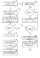
図1Bは、フィーチャ厚制御を用いるジェネレーティブ設計のプロセスの例を示す。モデル化されたオブジェクトの設計空間と1つ以上の設計基準とが、ジェネレーティブ3Dモデルの作成で用いるために、例えば、CADプログラム(複数可)116によって取得される(180)。モデル化されたオブジェクトの設計空間は、パーツがその内部で設計されることになるボリュームである。設計空間には、オブジェクトの3Dトポロジの1つ以上の外形の初期仕様を含む境界ボリュームが含まれ得る。上記のように、設計空間は、記載されたジェネレーティブ設計プロセスの最適化ドメインのサブスペースとして機能する、CADプログラム(複数可)116で設計された3Dモデル(複数可)、またはCADプログラム(複数可)116にロードされた3Dモデル(複数可)、及び/またはジェネレーティブ設計ジオメトリ制作の境界条件を指定するために使用される入力領域(例えば、保存ボディ及び/または保存サーフェス)のセット、例えば、UI122などのユーザインタフェースを介してユーザによって選択されて、より大きな3Dモデルまたは別個の3Dモデル(複数可)で他の構成要素(複数可)との接続点(複数可)として使用するために保存されるサブ領域(複数可)を指定するB-Rep(またはその面)、を含むことができる。
FIG. 1B illustrates an example process of generative design with feature thickness control. A design space and one or more design criteria for the modeled object are obtained 180, for example by CAD program(s) 116, for use in creating a generative 3D model. The design space of a modeled object is the volume within which the part will be designed. A design space may include a bounding volume that contains an initial specification of one or more outlines of the object's 3D topology. As noted above, the design space is the 3D model(s) designed in the CAD program(s) 116, or the CAD program(s) that serve as subspaces of the optimization domain of the described generative design process. ) 116, and/or a set of input regions (e.g., saved bodies and/or saved surfaces) used to specify boundary conditions for generative design geometry production, e.g.,
設計基準には、オブジェクトの設計目標(複数可)及び設計制約(複数可)が含まれ得る。設計目標には、廃材の最小化、パーツ重量の最小化、及びパーツのコンプライアンス、応力、またはその他の固有特性の最小化が含まれ得るが、設計目標は、これらに限定されず、形状合成プロセスをより良い設計に向けて推進するために使用される。必須ではないが、設計目標は、設計のシミュレーション(線形静的、流体力学的、電磁的なシミュレーションなど)に基づいているのが一般的である。設計制約には、生成される任意の設計で満たされるべき様々な幾何学的特性及び物理的特性または物理的挙動(個々のパーツまたはアセンブリ全体についての要件も認められる)が含まれ得、例としては、最大質量、荷重下での最大たわみ、最大応力などがある。 Design criteria may include design goal(s) and design constraint(s) for the object. Design goals may include, but are not limited to, minimizing scrap, minimizing part weight, and minimizing compliance, stress, or other inherent properties of the part. used to drive towards better design. Although not required, design goals are typically based on design simulations (linear static, hydrodynamic, electromagnetic simulations, etc.). Design constraints can include various geometric and physical properties or physical behaviors (requirements for individual parts or entire assemblies are allowed) that must be met for any design to be produced, such as is the maximum mass, maximum deflection under load, maximum stress, etc.
設計基準には、また、形状の幾何学的目標と幾何学的制約とが含まれ得る。幾何学的制約は、例えば、製造しやすい形状を提供するために、形状の特定の特性が確実に実現されるように、ユーザによって、またはCADプログラム(複数可)116から、提供することができる。例えば、幾何学的制約は、生成される形状に微細なフィーチャがないことを確実にするように定義することができる。入力ジオメトリは、システムの他のパーツへのインタフェースを構成するものとして設計に存在すべきである保存領域の詳細を含むことができ、または、境界条件(例えば、機械的負荷及び機械的制約)が適用されるべきである場所を特定することができる。 The design criteria may also include shape geometric goals and geometric constraints. Geometric constraints can be provided by the user or from the CAD program(s) 116 to ensure that certain characteristics of the shape are achieved, for example to provide a shape that is easy to manufacture. . For example, geometric constraints can be defined to ensure that the generated shape is free of fine features. The input geometry can include details of conserved regions that should be present in the design as they form an interface to other parts of the system, or if boundary conditions (e.g. mechanical loads and constraints) are It can specify where it should be applied.
さらに、設計パラメータと設計変数との様々な組み合わせを使用することにより、様々なジェネレーティブ設計プロセスを定式化することができる。いくつかの実施態様では、設計パラメータは、例えば、システム100内のCADプログラム(複数可)によって利用可能にされる異なるジェネレーティブ設計合成法の中から選ばれたものなど、UI122を介して受け取られる様々なタイプの入力を含むことができる。いくつかの実施態様では、利用可能なジェネレーティブ設計合成法は、トポロジ最適化のための基本的なレベルセット法を提供するレベルセットベースのトポロジ最適化を含むことができる。他のジェネレーティブ設計合成法も可能であり、システム100内のCADプログラム(複数可)によって提供することができる。設計パラメータと設計変数との異なる組み合わせが、例えば、ユーザ160からの入力に応答して、CADプログラム(複数可)116によって使用され得る。例えば、ユーザ160は、異なるジェネレーティブ設計合成法を選択して、単一の3Dモデル内のそれぞれ異なる設計空間内で使用することができる。
Furthermore, different generative design processes can be formulated by using different combinations of design parameters and design variables. In some implementations, the design parameters are various received via
得られた(180)1つ以上の設計基準には、ジェネレーティブ設計によるパーツから製造されることになる物理構造のための1つ以上の使用中の荷重ケース(例えば、1つ以上の使用中の荷重ケースを指定する1つ以上の境界条件)が含まれ得る。1つ以上の使用中の荷重ケースは、数値シミュレーションのための設定、例えば、ジェネレーティブ設計されているパーツの最適化された3Dトポロジで使用されるFEAモデル中の要素の密度に関連付けることができる。ただし、本明細書で使用する「使用中の荷重ケース」とは、一般に、パーツの性能が評価される荷重及び制約の別個のグループを指し、流体流動シミュレーション、電磁(EM)挙動シミュレーション、マルチフィジックスシミュレーションなど、様々なタイプの物理シミュレーションの境界条件のセットに対応する。したがって、様々なタイプの境界条件、例えば、圧力及び/または速度の境界条件を使用できる。 The derived 180 one or more design criteria include one or more in-use load cases (e.g., one or more in-use load cases) for the physical structure to be manufactured from the generatively designed part. One or more boundary conditions that specify load cases) may be included. One or more of the load cases in use can be associated with settings for numerical simulation, e.g., density of elements in the FEA model used in the optimized 3D topology of the part being generatively designed. However, as used herein, "in-use load cases" generally refer to distinct groups of loads and constraints against which part performance is evaluated, including fluid flow simulations, electromagnetic (EM) behavioral simulations, multiphysics It supports a set of boundary conditions for various types of physics simulations, such as simulations. Therefore, various types of boundary conditions can be used, for example, pressure and/or velocity boundary conditions.
一般に、数値シミュレーションの設定には、シミュレートすべき1つ以上の物理的特性、及び実行すべき1つ以上のシミュレーションのタイプ、ならびに潜在的に代理モデリングまたはその他の近似方法が含まれ得る。いくつかの実施態様では、数値シミュレーションのタイプは、プログラムの全ての使用に対して事前定義されているか、またはジェネレーティブ設計プロセスが開始されたプログラムの特定のコンテキストに与えられている。さらに、数値シミュレーションの設定は、実行すべき数値シミュレーションのタイプに関連する荷重条件及び/または他の物理的環境情報の少なくとも1つのセットを含むことができる。 In general, a numerical simulation setup can include one or more physical properties to be simulated, and one or more types of simulations to be performed, and potentially surrogate modeling or other approximation methods. In some implementations, the type of numerical simulation is predefined for all uses of the program or given to the specific context of the program in which the generative design process was initiated. Additionally, the numerical simulation settings may include at least one set of load conditions and/or other physical environment information related to the type of numerical simulation to be performed.
最後に、得られた(180)1つ以上の設計基準は、モデル化されたオブジェクトの厚さ仕様を含むことができる。場合によっては、厚さ仕様は、最小厚値であり、生成されることになる3Dモデルの最小許容厚を示す。場合によっては、厚さ仕様は、最大厚値であり、生成されることになる3Dモデルの最大許容厚を示す。場合によっては、厚さ仕様は、厚さアスペクト比に対応し、これは、局所的な厚さと、その局所的な厚さの領域における3Dモデル部分の長さとの最小許容比率を示す。 Finally, the derived 180 one or more design criteria can include thickness specifications for the modeled object. In some cases, the thickness specification is a minimum thickness value and indicates the minimum allowable thickness of the 3D model to be generated. In some cases, the thickness specification is a maximum thickness value and indicates the maximum allowable thickness of the 3D model to be generated. In some cases, the thickness specification corresponds to a thickness aspect ratio, which indicates the minimum allowable ratio between the local thickness and the length of the 3D model portion in the region of that local thickness.
ジェネレーティブ設計空間及び設計基準が指定されたので、1つ以上のジェネレーティブ設計プロセスを使用して、例えばCADプログラム(複数可)116により、1つ以上の3Dモデル(複数可)が制作される(185)。いくつかの実施態様では、制作された3Dモデル(複数可)は、上記のように、付加製造、除去製造(例えば、2.5軸除去製造プロセスを使用して製造される)、及び/または他の製造システム及び技法で用いるために設計することができる。例えば、CADプログラム(複数可)116によって実行される1つ以上のジェネレーティブ設計プロセスは、トポロジ最適化の境界ベースのジェネレーティブ設計プロセス(例えば、レベルセット法を使用する)、密度ベースのジェネレーティブ設計プロセス(例えば、SIMP法を使用する)、またはその両方を含み得る。 Once the generative design space and design criteria have been specified, one or more 3D model(s) are produced 185 using one or more generative design processes, such as by CAD program(s) 116. ). In some embodiments, the 3D model(s) produced are additive manufacturing, subtractive manufacturing (e.g., manufactured using a 2.5-axis subtractive manufacturing process), and/or It can be designed for use with other manufacturing systems and techniques. For example, the one or more generative design processes executed by the CAD program(s) 116 may include a topology optimization boundary-based generative design process (e.g., using a level set method), a density-based generative design process ( for example using the SIMP method), or both.
いくつかの実施態様では、1つ以上のジェネレーティブ設計プロセスでは、記載されたレベルセット法を使用することができる。ただし、式(1)、(2)、及び(3)からのsは、背景グリッドまたはメッシュ上のサンプル値として保管することができる1つ以上のレベルセットを使用して暗黙的に表されるソリッド領域の境界を表す。符号付き距離フィールドは、このようなレベルセット関数の例であり、ここで、ゼロ輪郭は形状境界を表し、関数の正の値は、材料ドメインの外部にある点に対応し、その点と最も近いドメインサーフェスとの間の距離を定量化するものであり、負の値は、材料ドメインの内部にある点に対応し、その点と最も近いドメインサーフェスとの間の距離を定量化するものである。レベルセットベースのトポロジ最適化法では、構造の外形はレベルセット関数の輪郭で表され、形状及び構成の変化がレベルセット関数値の変化で表される。 In some implementations, one or more of the generative design processes can use the described level set method. However, s from equations (1), (2), and (3) is implicitly represented using one or more level sets that can be stored as sample values on a background grid or mesh. Represents the boundary of a solid region. The signed distance field is an example of such a level-set function, where the zero contour represents the shape boundary and the positive values of the function correspond to points lying outside the material domain, with the point and the most It quantifies the distance between the near domain surfaces, negative values correspond to points inside the material domain and quantify the distance between that point and the nearest domain surface. be. In the level-set-based topology optimization method, the outline of the structure is represented by the contour of the level-set function, and changes in shape and configuration are represented by changes in the value of the level-set function.
いずれにせよ、3Dモデル(複数可)の制作185は、例えば、CADプログラム(複数可)116により、モデル化されたオブジェクトのジェネレーティブ設計による3D形状を、厚さ仕様に基づいて、フィーチャ厚制御を用いて反復的に修正することを含む。これには、3D形状のジオメトリと3D形状のトポロジとの両方を修正することが含まれる(例えば、穴または空隙を追加して、引き裂かずに、連続変形に影響されないサーフェスの空間的性質を修正し、それによって3Dモデル内の形状要素の境界と接続の仕方とを変更する)。いくつかの実施態様では、3Dモデル(複数可)の制作185は、ボクセル化シート及びラインスケルトンを使用して3Dモデルの厚さを測定することを含む。いくつかの実施態様では、3Dモデル(複数可)の制作185は、傾斜スケーリング(ramped scaling)ベースの厚さ制約の使用、厚さ測定へのボクセル化シート及びラインスケルトンのアプローチの使用、または厚さ測定への別のアプローチの使用を含む。いずれの場合も、結果は、例えば、製造プロセスに関連して使用するための、少なくとも1つのジェネレーティブ3Dモデルになる。
In any event, the
ジェネレーティブ設計処理の結果は、例えば、ディスプレイデバイス120上のUI122において、設計を受け入れるかまたは拒否する選択肢190とともに、ユーザに提示され得る。例えば、ジェネレーティブ設計処理185によって制作された3Dモデルは、UI122にてユーザ160に提示することができる。いくつかの実施態様では、ユーザは、各設計検討について、最終設計、または様々な以前の反復のいずれかから選択することができる。いくつかの実施態様では、ジェネレーティブ設計プロセスからの結果として生じる2つ以上の3Dモデルを、例えば、必要となる外部支持構造の量、または他の様々な関心のある量のいずれかに基づいて、設計の複雑さ対製造コストのトレードオフ分析とともに、ユーザに提示することができる。トレードオフ分析は、ユーザ160が、提示された3Dモデルのうちの1つ以上の3Dモデルを受け入れるかまたは拒否するのを支援することができる。
The results of the generative design process may be presented to the user, for example, in
設計が拒否された場合、図1Bのプロセスは、例えばCADプログラム(複数可)116により、新しいジェネレーティブ3Dモデルを制作する際に用いるための新しい設計空間及び/または新しい設計基準を取得する(180)ために戻ることができる。設計が拒否されない(190)となれば、図1Bのプロセスは、例えば、CADプログラム(複数可)116により、物理構造の製造用にジェネレーティブ設計による形状及び/またはトポロジをオブジェクトの3Dモデルに提供する(195)ことができる。提供195は、製造システムを使用してオブジェクトに対応する物理構造を製造する際に使用するために、3Dモデルをパーマネントストレージデバイスへ送出すること、またはセーブすることを含み得る。いくつかの実施態様では、提供195は、例えば、CADプログラム(複数可)116により、3Dモデルを使用して、コンピュータ制御製造システム(複数可)のためのツールパス仕様を生成する(195A)ことを含み、例えば、CADプログラム(複数可)116により、ツールパス仕様を使用して、コンピュータ制御製造システム(複数可)で、オブジェクトに対応する物理構造の少なくとも一部分を製造する(195B)ことを含む。いくつかの実施態様では、提供195は、生成された(195A)ツールパス仕様を使用して、製造機械で、物理構造用の金型を製造する(195B)ことを含むことができ、この場合、3Dモデルは、除去製造プロセスを使用して製造されるようになる金型のモデルであり得る。 If the design is rejected, the process of FIG. 1B obtains (180) a new design space and/or new design criteria for use in creating a new generative 3D model, such as by the CAD program(s) 116. can go back for Once the design is not rejected (190), the process of FIG. 1B provides a 3D model of the object with generative design geometry and/or topology for fabrication of the physical structure, for example by CAD program(s) 116. (195) can. Providing 195 may include sending or saving the 3D model to a permanent storage device for use in manufacturing the physical structure corresponding to the object using the manufacturing system. In some implementations, providing 195 uses the 3D model, for example by CAD program(s) 116, to generate 195A toolpath specifications for computer controlled manufacturing system(s). and manufacturing (195B) at least a portion of the physical structure corresponding to the object, for example, with the CAD program(s) 116 using the toolpath specification in a computer controlled manufacturing system(s) . In some embodiments, providing 195 may include using the generated (195A) toolpath specification to manufacture (195B) a mold for the physical structure on a manufacturing machine, where , the 3D model may be a model of the mold to be manufactured using the subtractive manufacturing process.
提供される(195)3Dモデルは、ジェネレーティブ設計合成法によって制作された(185)3Dモデルまたはジェネレーティブ設計出力の後処理されたバージョンであり得る。いくつかの実施態様では、境界ベースのジェネレーティブ設計プロセスからの出力から抽出され得るポリゴンメッシュ、または境界ベースのジェネレーティブ設計プロセスから直接取得されるジェネレーティブ設計データを、例えば、CADプログラム(複数可)116により、境界表現(B-Rep)モデル及び/またはパラメトリックフィーチャモデルに変換することが可能である。例えば、ジェネレーティブ設計データは、境界ベースのジェネレーティブ設計プロセスから直接取得されたレベルセット距離フィールドデータであり得る。境界表現モデルまたはパラメトリックフィーチャモデルは、スケッチジオメトリ及びパラメトリックフィーチャとして編集可能であり得る。例えば、いくつかの実施態様では、提供される(195)前に、ジェネレーティブ設計合成法によって制作された3Dメッシュモデルを、防水型のB-Rep3Dモデルに変換することができる。 The 3D model provided (195) can be a 3D model produced (185) by a generative design synthesis method or a post-processed version of the generative design output. In some implementations, a polygon mesh, which may be extracted from the output from a boundary-based generative design process, or generative design data obtained directly from a boundary-based generative design process, is generated by, for example, the CAD program(s) 116. , boundary representation (B-Rep) models and/or parametric feature models. For example, generative design data can be level set distance field data obtained directly from a boundary-based generative design process. The boundary representation model or parametric feature model may be editable as sketch geometry and parametric features. For example, in some implementations, a 3D mesh model produced by generative design synthesis methods can be converted into a waterproof B-Rep 3D model before being served 195 .
図1Cは、フィーチャ厚制御を用いるジェネレーティブ設計のプロセスにおける反復ループの例を示す。この例は、図1Bの定義されたプロセス185で実行されるトポロジ最適化に相当する。モデル化されたオブジェクトの現在の数値的評価を生成するために、1つ以上の設計基準に従って、オブジェクトの現在の3Dモデル(例えば、3D形状の暗黙的サーフェスのレベルセット表現)に対して、数値シミュレーションが実行される(185A)。上記のように、設計基準には、使用中の荷重ケースまたはその他の要件(例えば、圧力と速度の境界条件、トポロジ進化の幾何学的目標など)を定義できる境界条件を含めることができ、現在の数値的評価を、モデル化されたオブジェクトの物理的応答(例えば、構造応答)に対するものとすることができる。さらに、上記のように、様々なタイプの数値シミュレーションを実行することができる。例えば、FEAシミュレーションでは、現在のバージョンの3Dモデルのボリューム内のあらゆる場所でひずみエネルギーを計算することができる。いずれの場合も、現在の3Dモデルの数値シミュレーションにより、現在の数値的評価が生成され、次いでこの評価を使用して、設計基準を考慮して、現在の3Dモデルの形状及びトポロジを変更することができる。
FIG. 1C shows an example of an iterative loop in the process of generative design with feature thickness control. This example corresponds to the topology optimization performed in defined
さらに、現在の3Dモデルの厚さが測定される(185B)。厚さ測定185Bは、現在の3Dモデル上またはそのモデル中の多くの異なる位置で厚さ値を作成することができ、必ずしも数値シミュレーション185Aの後に(または数値シミュレーション185Aとは別に)行う必要がないことに留意されたい。いくつかの実施態様では、厚さ測定185Bは、数値シミュレーション185Aと統合されている。さらに、厚さ測定185Bでは、数値シミュレーション185Aに応答して変更可能である、現在の3Dモデルの各サーフェス位置で厚さ値を生成することができ、例えば、サーフェス上の各点について、形状の局所的な厚さを推定することができる。いくつかの実施態様では、以下の厚さ測定法の1つ以上が使用される。すなわち、(1)レイキャスティング法、(2)最大適合球探索、(3)ローリングボール法、及び(4)ラプラシアンに基づく中心軸への距離の計算である。
Additionally, the thickness of the current 3D model is measured (185B).
いくつかの実施態様では、ボクセル化間引きに基づく中心サーフェスへの距離のプロセスが使用される。このようなプロセスでは、現在の3Dモデルの3次元形状に対して、ボクセル化シート及びラインスケルトンが準備される(185B-1)。場合によっては、これには、保存領域を接続するループまたはラインスケルトン部分を削除しない適切な浸食アルゴリズムを使用して、シートスケルトン及びクリティカルラインスケルトンを単一パスで準備する(185B-1)ことが含まれる。場合によっては、これには、図2Aに関連して以下に記載されるような、2ステップのプロセスでシートスケルトン及びクリティカルラインスケルトンを準備する(185B-1)ことが含まれる。また、厚さ値を生成するために使用されるボクセルの寸法/解像度は、数値シミュレーション185A中に使用される任意のボクセルの寸法/解像度と同じであってもよく、または異なっていてもよいことに留意されたい。
In some implementations, a distance-to-central surface process based on voxelization decimation is used. In such a process, a voxelized sheet and line skeleton are prepared (185B-1) for the three-dimensional shape of the current 3D model. In some cases, this may involve preparing (185B-1) the sheet skeleton and critical line skeleton in a single pass using an appropriate erosion algorithm that does not remove loops or line skeleton parts connecting conserved regions. included. Optionally, this includes preparing the sheet skeleton and critical line skeleton (185B-1) in a two-step process, as described below with respect to FIG. 2A. Also, the voxel dimensions/resolution used to generate the thickness values may be the same as or different from any voxel dimensions/resolution used during the
さらに、ボクセル化シート及びラインスケルトンを使用して、3次元形状の厚さ値を定義することができる(185B-2)。これには、ボクセル化シート及びラインスケルトンを、3次元形状の中心サーフェスに近い点に変換し、これらの点を用いて厚さ値を生成することが含まれ得る。例えば、骨格シートの各ボクセルについて、その骨格シートのボクセルの中心よりも3次元形状の真の中心サーフェスに近い点を、以下にさらに詳しく記載するように、符号付き距離フィールドのようなレベルセット表現を用いた近似を行うことによって見つけることができる。いくつかの実施態様では、これらの精密化された骨格点を使用して厚さ値を生成することは、図2A~図2Lに関連して以下でさらに詳細に記載するように、厚さが必要とされるサーフェス点に最も近い骨格点を探索することと、次に、その最も近い骨格点の半径(または半径の2倍)をサーフェス点での厚さとして使用するか、またはサーフェス点とその最も近い骨格点との間の距離(または距離の2倍)を計算するかのいずれかと、を含む。 Additionally, the voxelized sheet and line skeleton can be used to define thickness values for the three-dimensional shape (185B-2). This may involve converting the voxelized sheet and line skeleton into points close to the central surface of the 3D shape and using these points to generate thickness values. For example, for each voxel of the skeletal sheet, the points that are closer to the true central surface of the three-dimensional shape than the center of the voxel of that skeletal sheet are represented by a level set representation, such as a signed distance field, as described in more detail below. can be found by performing an approximation using In some implementations, using these refined skeletal points to generate the thickness values is the thickness is Find the closest skeleton point to the required surface point, and then use the radius (or twice the radius) of that closest skeleton point as the thickness at the surface point, or and either calculating the distance (or double the distance) between its nearest skeleton points.
3Dモデルの3D形状は、厚さ制約を考慮して更新される(185C)。一般に、数値シミュレーション185Aからの数値的評価は、設計基準に関して3Dモデルを改善するために、3Dモデルの様々な位置(例えば、3Dモデルの3D形状のサーフェス上の位置)でいくらかの変化量を示し、この表示が形状更新185Cのための基準として使用される。例えば、いくつかの実施態様では、モデル化されたオブジェクトのジェネレーティブ設計による3D形状は、モデル化されたオブジェクトの暗黙的サーフェスのレベルセット表現を含み、更新185Cは、現在の物理的評価に基づいて暗黙的サーフェスに対して計算された形状変化速度に従って、レベルセット表現を更新することを含む。例えば、(数値シミュレーションによって求められた)ボリューム内部のひずみエネルギー場を、そのボリュームのサーフェスの速度フィールドに変換し、そして各点の速度によってジオメトリをより最適な形状に移動し、境界の各ピースをその速度に従って移動させることにより、3D形状を移流させて更新することができる。さらに、モデル化されたオブジェクトの3D形状は、シミュレーションのため立方ボクセルのグリッドを使用して3D形状を表現すること、形状更新のために暗黙的形状を使用すること、及び多角形メッシュを使用してジェネレーティブ設計をエクスポートすることなど、様々な処理段階時に異なる形式で表現することができる。
The 3D shape of the 3D model is updated 185C to take into account the thickness constraint. In general, the numerical evaluation from
いずれの場合も、形状更新185Cでは厚さ制約を考慮に入れる。様々なアプローチを、様々な実施態様で使用することができる。これには、(1)シミュレーション185Aからの数値的評価を3Dモデルの形状/ボリュームのサーフェスの速度フィールドに変換するときに、厚さ仕様を考慮した形状導関数を使用すること、(2)速度フィールドをフィルタリングするための経験則(例えば、サーフェスメッシュに基づく経験則)を用いること、及び(3)感度またはジオメトリのフィルタリングが含まれる。一般に、厚さ制約を適用するには、測定された厚さ値を最適化プロセスにおける何らかの変更、例えば、ジェネレーティブ設計の薄すぎる領域にペナルティを課すこと、及び/または削除することに対応させる必要がある。
In either case,
いくつかの実施態様では、速度フィールド(モデル化されたオブジェクトの現在の数値的評価によって示される変化の量を指定する)が修正され(185C-1)、次に、3Dモデルの形状が、修正された速度フィールドを使用して移流される(185C-2)。一般に、このプロセスは、形状の境界上の各点で測定された厚さを、形状最適化の各反復での速度フィールドの変化に対応させる。少なくとも、修正185C-1は、厚さ仕様に向かう方向への形状変化を(ジェネレーティブ設計による3次元形状の現在のバージョンでの複数の場所のそれぞれで)、測定された厚さが厚さ仕様に従うときに、その場所での厚さ仕様と測定された厚さとの間の差に基づく量だけ、緩やかにすることを含む。例えば、最小厚さ制約の場合、プロセスは、すでに最小フィーチャサイズに近いフィーチャの収縮を緩やかにし、最小フィーチャサイズに達したときに、そのようなフィーチャの収縮を停止することができる。さらに、このプロセスでは、最小フィーチャサイズカットオフよりも小さいフィーチャを大きくすることができる。厚さ制約を適用するための傾斜スケーリングプロセスに関するさらなる詳細は、図4A及び図4Bに関連して以下に提供される。
In some implementations, the velocity field (specifying the amount of change exhibited by the current numerical evaluation of the modeled object) is modified (185C-1) and then the shape of the 3D model is modified (185C-2) using the modified velocity field. In general, this process associates the thickness measured at each point on the boundary of the shape with changes in the velocity field at each iteration of shape optimization. At a minimum,
形状修正ループの各反復が完了した後に、プロセスは最終形状への収束をチェックする(185D)。これは、反復回数が、完了すべき形状修正の予め定められた反復回数に相当するとき、及び/または、修正が3D形状をもはや変化させない(または、もはや大幅に変化させない)ため、さらなる反復が3Dモデルを改善しないときのように、暗黙的収束である場合がある。追加的または代替的に、チェック185Dは、現在の3Dモデルが形状及び/またはトポロジ最適化の設計基準を満たしているかどうかを評価することにより、明示的な収束に関して行うことができる。(暗黙的または明示的な)収束185Dが達成されていない場合、最適化ループの別の反復が開始される。(暗黙的または明示的な)収束185Dが達成されると、例えば製造で使用するために、ジェネレーティブ設計によるオブジェクトの3Dモデルが提供される(185E)。
After completing each iteration of the shape modification loop, the process checks for convergence to the final shape (185D). This is because when the number of iterations corresponds to a predetermined number of iterations of the shape modification to be completed and/or because the modification no longer changes (or no longer significantly changes) the 3D shape, further iterations Sometimes there is implicit convergence, such as when not improving the 3D model. Additionally or alternatively, a
図2Aは、3Dモデルの厚さを測定するためのボクセル化間引きに基づく中心サーフェスへの距離のプロセスの例を示す。3次元形状のボクセル化シートスケルトンが計算される(200)。これは、ボクセル化された中心サーフェスを計算するように設計された間引きアルゴリズム(Building Skeleton Models via 3-D Medial Surface/Axis Thinning Algorithms;Lee,Ta-Chih and Kashyap,Rangasami;6,s.l.:Academic Press,Inc.,1994;CVGIP:Graphical Models and Image Processing,Vol.56,pp.462-478などに記載されており、以降で「リーアンドカシャプアルゴリズム」とする)を使用して行うことができる。ボクセル化された中心サーフェスは、3D形状の中心サーフェスの大まかな近似である。概念的には、中心サーフェス(「シートスケルトン」とも呼ばれる)は、形状境界上の2つ以上の最も近い点から等距離にある点の集合である。 FIG. 2A shows an example of a distance-to-central-surface process based on voxelization decimation to measure the thickness of a 3D model. A voxelized sheet skeleton of the 3D shape is calculated (200). This is a thinning algorithm designed to compute a voxelized central surface (Building Skeleton Models via 3-D Medial Surface/Axis Thinning Algorithms; Lee, Ta-Chih and Kashyap, Rangasami; 6, sl. : Academic Press, Inc., 1994; CVGIP: Graphical Models and Image Processing, Vol. be able to. The voxelized central surface is a rough approximation of the central surface of the 3D shape. Conceptually, a central surface (also called a "sheet skeleton") is a set of points that are equidistant from two or more closest points on the shape boundary.
図2Bは、形状200Aの中心軸の例を示す。この例は、提示を容易にするために2次元であるが、2Dの形状の中心軸は、3Dの形状の中心サーフェスに対応し、2Dの円が3Dの球に置き換えられることが理解されよう。2箇所以上で形状の境界に接し、完全に形状の内側に含まれる円200Bの集合を作成することによって、中心軸を視覚的に見つけることができる。このような円の中心は、形状の境界上の2点から等距離にある点であるため、内接円の中心200Cの集合は、形状の中心軸に相当する。同様に、(2箇所以上で3D形状の境界に接している)球の集合は、3D形状の中心サーフェスに相当する。
FIG. 2B shows an example of the central axis of
中心サーフェスが確立されると、形状境界の厚さを、境界上のその点に接触する球の直径を調べることによって計算できる。ただし、特に3D形状が、反復最適化プロセスで進化しているとき、及び場合によっては非常に複雑なトポロジを有するとき、計算効率が高く堅牢な方法で3D形状のおおよその中心サーフェスを見つけることは簡単ではない。計算効率の高い方法で高品質の結果を提供する堅牢なアルゴリズムを提供するには、いくつかの要因を考慮しなければならない。 Once the central surface is established, the thickness of the shape boundary can be calculated by looking at the diameter of the sphere contacting that point on the boundary. However, finding the approximate central surface of a 3D shape in a computationally efficient and robust manner is not possible, especially when the 3D shape is evolving in an iterative optimization process, and in some cases has a very complex topology. It is not easy. Several factors must be considered in order to provide robust algorithms that provide high quality results in a computationally efficient manner.
第一に、中心サーフェスの近似は、実際の中心サーフェスを適切にカバーするために必要な数の点で構成されるべきである。図2Cは、形状の中心サーフェスの近似の例を示す(提示を容易にするために2Dで表されている)。図2Cでは、形状は実線で表され、実際の中心サーフェスは破線で表され、中心サーフェスの近似は小さな円で表されている。例202Aと202Bとを比較すると、例202Aには、例202Bよりも多くの近似のデータ点(小さな円)があることに留意されたい。したがって、例202Bは、例202Bが依然として十分に中心サーフェスをカバーする中心サーフェスの比較的薄い近似を有するという点において、第1の考察に関して例202Aよりも好ましい。 First, the approximation of the central surface should consist of as many points as necessary to adequately cover the actual central surface. FIG. 2C shows an example of an approximation of the central surface of the shape (represented in 2D for ease of presentation). In FIG. 2C, the shape is represented by a solid line, the actual center surface by a dashed line, and the approximation of the center surface by a small circle. Comparing examples 202A and 202B, note that example 202A has more approximate data points (small circles) than example 202B. Therefore, example 202B is preferred over example 202A for the first consideration in that example 202B still has a relatively thin approximation of the central surface that sufficiently covers the central surface.
第2の考慮事項は、近似のデータ点は、形状の対応する境界から等距離に配置されるべきであるということである。この結果として、近似のデータ点が実際の中心サーフェスをより正確に追跡するので、例202Cは例202Bよりも好ましい。ただし、第3の考慮事項は、ギャップ/穴または欠落領域がないという意味で、近似は「連続的」であるべきであるというものである。したがって、例202Dは、形状の中心サーフェスに近づけるためのデータ点が欠落している領域を含んでいるため、受け入れられない。これらの考慮事項は、非常に正確で薄い中心サーフェス近似を生成するためにかけられた手間がまた、中心サーフェス近似にギャップ及び穴が残る可能性、またはそれどころか領域が完全に欠落する可能性を高める場合があるという点において、トレードオフを生み出す。 A second consideration is that the approximate data points should be placed equidistant from the corresponding boundaries of the shape. As a result of this, example 202C is preferred over example 202B because the approximate data points more accurately track the actual center surface. A third consideration, however, is that the approximation should be "continuous" in the sense that there are no gaps/holes or missing regions. Therefore, example 202D is not acceptable because it contains regions missing data points to approximate the central surface of the shape. These considerations are useful if the effort put into producing a very accurate and thin center surface approximation also increases the likelihood that the center surface approximation will have gaps and holes left in it, or even be missing regions entirely. creates a trade-off in that there is
このことは、形状及び/またはトポロジ最適化との関連で重要になり得る。ギャップ及び穴を含む中心サーフェス近似を使用すると、表面ノイズを引き起こし、それが制作される3D形状の品質を低下させ、検出されない厚さ制約違反をもたらす可能性がある。欠落領域を含んで中心サーフェス近似を使用すると、ビームが中断し、したがってジェネレーティブ設計プロセスで最適なトポロジを見つけることが妨げられる。さらに、トポロジ最適化中に中心サーフェス近似をベースにした厚さ測定を使用するとき、2つの追加の考慮事項が関係する。 This can be important in the context of shape and/or topology optimization. Using a central surface approximation that includes gaps and holes can introduce surface noise, which degrades the quality of the 3D shape produced, and can lead to undetected thickness constraint violations. Using a center surface approximation with missing regions breaks the beam and thus prevents the generative design process from finding the optimal topology. In addition, two additional considerations are relevant when using central surface approximation-based thickness measurements during topology optimization.
いくつかの実施態様では、厚さ測定は、形状の「重要でない」フィーチャを拒否するように設計されており、これにより、アーチファクトが、トポロジ最適化が進むにつれて、時間とともに消えてなくなるのではなく、フリーズされて保持され得る。例えば、機械的コンプライアンスの最小化との関連では、3Dモデルに1つ以上の「指部」が含まれるとき、これは、他の何にも接続せず、そのため荷重経路として機能し得ない形状から突出したものであり、トポロジ最適化プロセスでは、3D形状のこれらの部分を削除すべきであり、厚さ測定プロセスでは、これが発生するのを防ぐ必要はない。さらに、厚さ測定は、現在の3D形状の薄い材料シートの2つの面と、その薄い材料シートのエッジとを区別するように設計することができる。例えば、最小厚さ制約を使用するとき、薄い材料シートの2つの面が互いに近づくのを防ぐ必要があるが、シートのエッジは形状変化の各反復で自由に動ける必要がある。ただし、形状の「重要でない」フィーチャは、厚さ測定プロセスの適用状況によって変わり得ることに留意されたい。いくつかの実施態様では、「重要でない」フィーチャを拒否することは適切ではない場合があるため、熱伝達トポロジ最適化問題(例えば、ヒートシンクの設計)との関連で、または厚さの視覚化もしくはトポロジ最適化以外の他の用途との関連で、厚さ測定のこの態様を排除することが可能である。 In some implementations, the thickness measurements are designed to reject 'unimportant' features of the shape, so that the artifacts do not fade away over time as the topology optimization progresses. , can be kept frozen. For example, in the context of minimizing mechanical compliance, when a 3D model contains one or more "fingers", this is a shape that does not connect to anything else and thus cannot serve as a load path. , the topology optimization process should remove these parts of the 3D shape, and the thickness measurement process need not prevent this from happening. Additionally, the thickness measurement can be designed to distinguish between the two sides of the current 3D shape thin material sheet and the edge of the thin material sheet. For example, when using a minimum thickness constraint, the two faces of a thin sheet of material should be prevented from coming close to each other, but the edges of the sheet should be free to move with each iteration of the shape change. However, it should be noted that the "non-critical" features of the shape may vary depending on the application of the thickness measurement process. In some implementations, in the context of heat transfer topology optimization problems (e.g., heat sink design) or thickness visualization or In the context of other applications other than topology optimization, it is possible to eliminate this aspect of thickness measurement.
いずれにせよ、現在の3Dモデルのボクセル化された中心サーフェスを計算するために間引きアルゴリズムを使用することで、ギャップ/穴または欠落領域のない、中心サーフェスの比較的薄い近似を迅速に計算できるという点で、第1及び第3の考慮事項に対処する。間引きアルゴリズムは、滑らかな3D形状を取得し、それを固定サイズのボクセルの離散集合として表すことによって機能する。ボクセルは、薄くされた形状のトポロジが入力形状のトポロジと一致することを保証する一連のルールに従って、形状のサーフェスから連続的に削除される。リーアンドカシャプアルゴリズムの使用により、単一ボクセル幅の「中心軸」のみが残るまで、ボクセルをさらに選り抜く変形形態が提供されることに留意されたい。中心サーフェスは3D空間に埋め込まれた2Dマニホールド(湾曲したサーフェスの集合)であるのに対し、中心軸は曲線(1Dマニホールド)のみで構成されるまでトリミングされる。中心サーフェスと同様に、中心軸は入力形状のトポロジを保持し(穴、ループ、及びビームが全て表現される)、リーアンドカシャプアルゴリズムのこの機能を、いくつかの実施態様で使用することができる。 In any case, by using a decimation algorithm to compute the voxelized central surface of the current 3D model, we can quickly compute a relatively thin approximation of the central surface without any gaps/holes or missing regions. address the first and third considerations. Decimation algorithms work by taking a smooth 3D shape and representing it as a discrete set of fixed-size voxels. Voxels are successively removed from the surface of the shape according to a set of rules that ensure that the topology of the thinned shape matches that of the input shape. Note that the use of the Lean and Kashyap algorithm provides a variant that further culls voxels until only a single voxel wide "central axis" remains. The central surface is a 2D manifold (collection of curved surfaces) embedded in 3D space, while the central axis is trimmed down to consist only of curves (1D manifold). Like the central surface, the central axis preserves the topology of the input shape (holes, loops, and beams are all represented), and this feature of the Lean and Kashyap algorithm can be used in some implementations. can.
図2Aに戻り、3次元形状に対するボクセル化ラインスケルトンが計算される(205)。これは、リーアンドカシャプアルゴリズムまたは別の間引きアルゴリズムを使用して実行できる。いくつかの実施態様では、ボクセル化ラインスケルトンは、3次元形状の異なる部分を互いに接続する1つ以上のラインセグメントを含む。例えば、1つ以上の保存領域があるとき、1つ以上の保存領域が結果に含まれることが要求されるボクセル化ラインスケルトンを計算する(205)ことができ、したがって生成されたラインスケルトンは1つ以上の保存領域のそれぞれと接続されることになる。保存領域がないとき、計算された(205)ボクセル化ラインスケルトンは、トポロジの他の部分を互いに接続する任意の部分を維持するように、端を持つ任意の枝上の全てのボクセルを浸食した後に残るラインスケルトンであり、すなわち、ループがトポロジの異なる部分を接続するため、ループは形状をまとまりのある全体として維持するために必要とされ、一方で、設計のうちの指部または他の「重要でない」フィーチャを形成するラインスケルトンの領域は削除される。 Returning to FIG. 2A, a voxelized line skeleton for the 3D shape is computed (205). This can be done using the Lean and Kashyap algorithm or another decimation algorithm. In some implementations, the voxelized line skeleton includes one or more line segments connecting different portions of the three-dimensional shape to each other. For example, when there is more than one conserved region, a voxelized line skeleton can be computed 205 that requires more than one conserved region to be included in the result, so the generated line skeleton is 1 It will be connected to each of the one or more storage areas. In the absence of conserved regions, the computed (205) voxelized line-skeleton eroded all voxels on any branch with an edge so as to preserve any part that connects other parts of the topology to each other. It is the line skeleton that remains behind, i.e. loops are needed to maintain the shape as a cohesive whole, as they connect different parts of the topology, while the fingers or other " Regions of the line skeleton that form "non-critical" features are removed.
図2Dは、3次元形状206のボクセル化シートスケルトン206Aの例、及び3次元形状206のボクセル化ラインスケルトン206Bの例を示す。保存領域が1つ以上あるとき、3次元形状のボクセル化シートスケルトンを計算する(200)ときに、これらの保存領域が結果に存在する必要はないことに留意されたい。実際に、そうすると、シートスケルトンが実際の3次元形状の中心サーフェスから外れる可能性がある。したがって、リーアンドカシャプアルゴリズムを使用して、まずボクセルをボクセル化シートスケルトンにまで浸食し、次にこのボクセル化シートスケルトンをボクセル化ラインスケルトンにまで浸食するなど、演算200と演算205とを1つの演算にまとめず、明示的に別々の演算として行うことにより、プロセスの結果の精度を向上させることが可能である。
FIG. 2D shows an example
また、いくつかの実施態様では、シートスケルトンにないボクセルがラインスケルトンにあるとき(210)、これらのボクセルは後で使用するために追跡される(215)。いずれにせよ、離れた所にあるボクセルがボクセル化シートスケルトンから除去され(220)、次にボクセル化ラインスケルトンのボクセルがボクセル化シートスケルトンに加えられて(225)、3Dモデルの局所厚さの測定に使用される、3次元形状用のボクセル化シート及びラインスケルトンが形成される。除去220は、3次元形状のボクセル化シートスケルトンのシートエッジに関連するボクセルの除去を伴う場合がある。いくつかの実施態様では、シートスケルトンから浸食されるボクセルの数が調整パラメータであり、その場合、浸食が増えるとエッジの厚さの測定値が増加するため、薄いシートのエッジでの形状変化に対する望ましくない制限が回避される。除去220は、3次元形状のボクセル化シートスケルトンのうちの1つ以上のボクセル化ラインスケルトン部分を形成するボクセルを除去することを含み得る。したがって、現在の形状の「指部」のボクセルを削除することができ、これにより、トポロジ最適化プロセス中に3D形状から不要な突出部を排除することが促進される。
Also, in some embodiments, when there are voxels in the line skeleton that are not in the sheet skeleton (210), these voxels are tracked (215) for later use. In any event, the distant voxels are removed from the voxelized sheet skeleton (220), then the voxels of the voxelized line skeleton are added to the voxelized sheet skeleton (225) to obtain the local thickness of the 3D model. A voxelized sheet and line skeleton for the three-dimensional shape used for measurement are created.
図2Eは、ボクセル化シート及びラインスケルトンの別の例を示す。初期のボクセル化シートスケルトン227Aが、3次元形状227に対して(例えば、リーアンドカシャプアルゴリズムを使用して)計算される(200)。シートのエッジ227B及び縮退したラインセグメント227Cに関連する、このシートスケルトン227A内のボクセルが識別され、除去される(220)。骨格シートのエッジを削除すると、シートエッジの測定された厚さが暗黙的に増加する。このことは、シートの内部が収縮してもシートのエッジが収縮するのを防ぐことができないため、最小厚要件を使用したトポロジ最適化との関係においては望ましい(ただし、視覚化アプリケーションに厚さ測定を使用する場合など、一部のコンテキストでは、3Dモデル全体に対して正確な厚さ測定が望まれるため、削除220は行われないことに留意されたい)。骨格シートエッジの除去220はまた、骨格シートのエッジの周りに存在することがあるノイズを低減させる。ベースシートスケルトンに存在するラインスケルトン(複数可)の一部のセグメントは、アルゴリズムのノイズ、または人工突出部227Cなどの、形状の構造にとって重要ではないパーツからの突出部によっても引き起こされる。
FIG. 2E shows another example of a voxelized sheet and line skeleton. An initial
重要なラインスケルトンセグメントを識別するために、ボクセル化ラインスケルトン227Dが、結果に存在する必要のある各保存ボディ227Eを備えた3次元形状227について(例えば、リーアンドカシャプアルゴリズムを使用して)計算される(205)。したがって、3次元形状227について識別された全てのシートエッジ227B及びラインスケルトンセグメント227Cを取り去ること(220)、ボクセル化ラインスケルトン227Dを加え戻すこと(225)、ならびに最後に保存ボディ227Eを全て除去して最終的なボクセル化シート及びラインスケルトン227Fを生成すること、により、最終的なボクセル化シート及びラインスケルトン227Fを生成することが可能である。
To identify the line-skeleton segments of interest, a voxelized line-
いくつかの実施態様では、ボクセル化シート及び/またはラインスケルトンの計算200、205は、計算の数を減らし、したがってプロセスの速度を上げるために、3D形状全体ではなく、測定が必要となる3D形状の領域に対してのみ行われることに留意されたい。例えば、最小厚さ制約を適用するという状況の中では、厚さは、最大値(最小厚値に従って設定)からゼロに至るまでの厚さ値の範囲内で測定されれば十分である。したがって、プロセスを高速化するために、符号付き距離フィールド(SDF)を使用して、測定すべき最大値よりも境界から遠い内部ボクセルの1つ以上の領域を分離し、次に、これらの領域(複数可)を、スケルトン計算、精密化、及びその後の全ての演算のために無視することが可能である。すなわち、中心サーフェス、中心軸などの計算を、任意選択のバッファ量に加えて最小厚仕様の半分よりも3D形状の境界から離れていないという理由から着目した3Dモデルの部分に限定することができる。いくつかの実施態様では、「遠いボクセル」(最小厚の半分に1ボクセルほどを加えたものの負より小さいSDF値に関連付けられるボクセル)のセットが識別され、この遠いボクセルのセットは、間引きアルゴリズムがそれらを取り除くことに反復を費やさないように(保存領域がクリティカルラインスケルトン計算に含まれるのと同様に)ライン及びシートスケルトン計算に含まれるよう要求される。そして、次の手順に進む前に、結果のシート及びクリティカルラインスケルトンから、遠いボクセルが取り去られる。
In some implementations, the voxelized sheet and/or
いずれにせよ、間引きアルゴリズムを使用することで、最終的なボクセル化シート及びラインスケルトンが、任意の保存領域の外にある3Dモデルの全ての部分(または全ての関連部分)に、ボクセルの1つ以上の連結集合を確実に提供するが、これらのボクセルの中心は、多くの場合、3Dモデルの中心サーフェスに正確に配置されない。これにより、実際には真の中心サーフェスから同じ距離にある、異なるサーフェスで、異なる厚さの測定値が得られる可能性があるため、実際の中心サーフェスに、より接近して追従する最終的な点のセットを生成するために、精密化プロセスを使用してもよい。 In any case, by using the decimation algorithm, the final voxelized sheet and line-skeleton will be added to all parts (or all relevant parts) of the 3D model outside any storage region, one of the voxels. While reliably providing the above connected sets, the centers of these voxels are often not exactly located on the central surface of the 3D model. This may result in different thickness measurements on different surfaces that are actually at the same distance from the true central surface, so the final A refinement process may be used to generate the set of points.
図2Aに戻ると、ボクセル化シート及びラインスケルトンは、3Dモデルの中心サーフェスをよりよく近似する点に変換される(230)。いくつかの実施態様では、3D形状の中心サーフェスに近づける点の第1のセットが見つけられ(232)、次に、点の位置値及び/または「半径」値を、その近隣(すぐ隣の点または点の事前定義された距離内の全ての点)またはその近隣及びそれ自体からのデータ値の平均または中央値に変更することによって、第1の点のセットのデータ値が平滑化される(234)。加重平均結果に対して各近隣が与える影響を選択するための重み付けなど、他の平滑化234の操作も可能である。骨格点のこの平滑化234は、最終的な3D形状のサーフェス品質を向上させることができるが、この平滑化は任意選択であり、用途によっては必要ない場合があることに留意されたい。例えば、ノイズの多いデータ値は、アニメーション制作用に生成される3Dサーフェス(複数可)では望ましくないものではない場合があり、増幅されることがある。点の位置は設計空間の座標系にあり、点の「半径」はその位置での厚さの半分に相当し、例えばレベルセット実施態様の場合では、その点での符号付き距離フィールドの負の値に相当することに留意されたい。 Returning to FIG. 2A, the voxelized sheet and line skeleton are transformed (230) into points that better approximate the central surface of the 3D model. In some implementations, a first set of points that approximates the central surface of the 3D shape is found (232), then the point's position and/or "radius" values are compared to its neighbors (nearest neighbors). or all points within a predefined distance of the point) or the average or median of the data values from its neighbors and itself are smoothed ( 234). Other smoothing 234 operations are possible, such as weightings to select the contribution each neighborhood has to the weighted average result. Note that this smoothing 234 of skeletal points can improve the surface quality of the final 3D shape, but this smoothing is optional and may not be required for some applications. For example, noisy data values may not be undesirable in the 3D surface(s) generated for animation production and may be amplified. The position of a point is in the coordinate system of the design space, and the "radius" of a point corresponds to half the thickness at that position, e.g. Note that it corresponds to the value
さらに、いくつかの実施態様では、除去220の前にはボクセル化シートスケルトンになかったボクセル化ラインスケルトンのボクセルが追跡され(215)、これらのボクセルは、精密化が必要ない、または可能ではない(例えば、以下に詳細に記載するように、検出されるべき符号付き距離フィールドのピークがない)点の第2のセット(例えば、これらのボクセルの中心点)を提供する。これらのボクセルは、(例えば、保存領域を接続するため)形状をまとまりのある全体として維持するために必要であり、これらの追加されたラインスケルトンピースが実際には3Dモデルの中心サーフェスの近くにない、いくつかの状況がある。したがって、これらのボクセルを使用して、オプティマイザが保存領域の近くで望ましくない間引きを行うのを防ぐことができる厚さの尺度を提供することができる。
Additionally, in some embodiments, voxels of the voxelized line skeleton that were not in the voxelized sheet skeleton prior to
上記の(近似のデータ点は、形状上の対応する境界から等距離に配置されるべきであるという)第2の考慮事項に対処するために、骨格シートのボクセルを骨格点位置に変換する(230)ことは、ボクセルによって示される点(例えば、ボクセル中心点)を3D形状の中心サーフェスに近づけるように精密化することを含むことができる。レベルセットベースの実施態様では、レベルセットからの情報を使用して骨格点位置を精密化することができる。いくつかの実施態様では、このプロセスは、線形近似を使用して骨格ボクセルの近傍の符号付き距離フィールドを近似することと、次いで2つのラインセグメントの間の交点を見つけることとを含む。これにより、中心サーフェスに非常に近い近傍点での、位置の推定値と、符号付き距離フィールド値との両方が提供される(実験的には、これは通常、約0.1ボクセル幅まで正確である)。 To address the second consideration above (that the approximate data points should be placed equidistant from the corresponding boundary on the shape), transform the skeletal sheet voxels into skeletal point locations ( 230) may include refining the point indicated by the voxel (eg, the voxel center point) to be closer to the central surface of the 3D shape. In a levelset-based implementation, information from the levelset can be used to refine the skeletal point locations. In some implementations, this process involves approximating a signed distance field in the vicinity of the skeletal voxels using a linear approximation and then finding the intersection between the two line segments. This provides both position estimates and signed distance field values at neighboring points very close to the central surface (experimentally, this is typically accurate to about 0.1 voxel width). is).
図2Fは、3D形状の中心サーフェスに近い骨格点を精密化するレイキャスティング及び極値推定のための幾何学的コンテキストを示す。入力形状231のボクセル化スケルトン232Aについて考える。アルゴリズムは、骨格ボクセルごとに1回実行される。この例では、強調表示された骨格ボクセル1が対処される。入力形状231の真の中心軸2に非常に近い(かつ開始ボクセルに可能な限り近い)点が求められる。これを行うには、ボクセルの中心(またはボクセル内もしくはボクセルに近い別の点、例えばボクセルの1ボクセル距離内の点)から出発して中心サーフェスに向かって進む方向3に、例えば風上勾配方向に沿って光線を投射することができる。この光線と真の中心軸との交点4は、アルゴリズムの意図した出力である。
FIG. 2F shows the geometric context for ray-casting and extremum estimation to refine skeleton points close to the central surface of the 3D shape. Consider the
図2Gは、勾配方向に沿った距離に対する符号付き距離値フィールドのプロットを示す。このプロットでは、x軸は光線に沿った移動距離を表し、Y軸は符号付き距離フィールド値φである。光線の出発点はボクセル(図2Fのボクセル1)の中心点とすることができ、図2Gの点Aに対応する。負の勾配方向に沿って2点(B1及びB2)をサンプリングすることが可能であり、正の方向に沿って2点(C1及びC2)をサンプリングすることが可能である。それぞれの点のペアに直線をフィットさせ、それぞれ直線B’及びC’を形成することができる。符号付き距離フィールドがあまり速く変化しない限り、これらの2つのラインセグメントの間の交点234Aは、光線と中心サーフェスとの交点(図2Fの点4)に近い。点Aは、2本のラインB’及びC’のいずれの上にもないことに留意されたい。これは投射光線がボクセルグリッドに対して斜めに発射され(実際のボクセルをサンプリングしていない)、データは全て補間されているためであり、つまり、Aは純粋なデータではなく、その隣接するいくつかの線形結合になることを意味する(符号付き距離フィールドの曲率が高いため、中心サーフェス付近ではトリリニア補間の精度が低下することに留意されたい。つまり、中心サーフェス付近の補間値は、サンプリング点が中心サーフェスの反対側にあることの結果として、通常、過大評価されることを意味する)。したがって、補間を使用しているため、Aが2本のラインのどちらかに収まることはほとんどない。重要な点は、線形補間により、Aよりも中心サーフェスに近い点に到達できることと、同様に線形補間により、符号付き距離フィールドの値をより正確に推定できることとである。
FIG. 2G shows a plot of the signed distance value field against distance along the gradient direction. In this plot, the x-axis represents distance traveled along the ray and the y-axis is the signed distance field value φ. The starting point of the ray can be the center point of the voxel (
いくつかの実施態様では、極値を推定することは、風上勾配の方向または大きさの変化を探すことを含み得る。最大値と最小値とのどちらが求められるかは、線形近似のY軸が半径値(SDF値の負の値)を表すか、それともSDF値を表すかによって決まることに留意されたい。いずれにせよ、推定された符号付き距離フィールド値φpは、この点での3Dモデルの厚さの推定値を提供する。出力点はボクセル座標ではなく3D空間にあるため、3Dモデルのサーフェスにマッピングし直すときに、サブボクセルの位置が使用されることに留意されたい。 In some implementations, estimating the extreme value may include looking for changes in the direction or magnitude of the upwind gradient. Note that whether the maximum or minimum value is sought depends on whether the Y-axis of the linear approximation represents radius values (negative of SDF values) or SDF values. In any case, the estimated signed distance field value φ p provides an estimate of the thickness of the 3D model at this point. Note that the output points are in 3D space rather than voxel coordinates, so the subvoxel positions are used when mapping back to the surface of the 3D model.
いくつかの実施形態では、この精密化手順は、1D精密化手順を使用して実施される。この1D精密化手順は、探索手順を開始するボクセル(最終的なボクセル化スケルトン上またはその近傍ボクセルである)の中心、及び探索する方向を入力として取り入れる関数であり、以下のように定義されている。

このルーチンの3つの主要な関数は、探索方向に沿って符号付き距離フィールドの谷底部にできるだけ近いボクセルを見つけようとするLocalize、線形近似を用いて中心サーフェスの交差の境界からの座標及び距離を推定するRefine、ならびにこの中心サーフェスの交点に対して、後述されるその後のステップで役に立つ品質尺度を作成するMeasureQualityである。
In some embodiments, this refinement procedure is performed using a 1D refinement procedure. This 1D refinement procedure is a function that takes as input the center of the voxel starting the search procedure (which is on or near the final voxelized skeleton) and the direction to search, and is defined as there is
The three main functions of this routine are Localize, which tries to find the voxel that is as close as possible to the valley floor of the signed distance field along the search direction; A Refine to estimate, as well as a MeasureQuality to create a quality measure for the intersection of this central surface that will be useful in subsequent steps described below.
Localize関数を使用して、点B1とB2及びC1とC2が中心サーフェスの交差の反対側に位置するために、図2Gの点Aが、中心サーフェスに十分に近接していない場合があるという事実に対処することができる。例えば、点C1が点B1及びB2の両方と同じ側に位置する場合、線形近似C’は中心サーフェスと交差せず、2つの線形近似B’とC’との交差は3D形状の実際の中心サーフェスに十分近くならない(例えば、中心サーフェスから半ボクセル以上離れている)。これは、場合によっては、2値形状を作成する際の離散化誤差と、間引きアルゴリズムでの材料除去率のわずかな不規則性との結果として発生する場合がある。 If point A in FIG. 2G is not close enough to the central surface because points B1 and B2 and C1 and C2 are on opposite sides of the central surface intersection can deal with the fact that there is For example, if point C1 lies on the same side of both points B1 and B2 , the linear approximation C' does not intersect the center surface and the intersection of the two linear approximations B' and C' is the 3D shape's Not close enough to the actual central surface (e.g. more than half a voxel away from the central surface). This may occur in some cases as a result of discretization errors in creating the binary shape and slight irregularities in the material removal rate in the decimation algorithm.
この問題に対処するために、第1の局所化操作を使用して、入力位置から探索方向(前方または後方)に沿って移動し、中心軸の交差にできるだけ近いボクセルを識別しようとすることができる。中心軸の交差に隣接するボクセルの1つを識別するだけでよいことに留意されたい。つまり、点AまたはC1のいずれかを識別する。中心サーフェスに最も近いボクセルは必要ない。したがって、いくつかの実施態様では、以下の局所化手順が使用される。

表2の局所化手順は、3つの部分で構成されている。最初に、符号付き距離フィールドが出発点のいずれかの側でサンプリングされて、より負の符号付き距離フィールドに対応する形状境界から、どちらの方向が、より遠くに至るかを判別する。次に、符号付き距離フィールド(SDF)の一連のサンプルが、移動方向に沿って1ボクセル単位で収集され、反対方向へ1ボクセルの後方ステップから開始され、結果が{s値、SDF値}のペアのリストに保管される。最後に、例えば1次の中央有限差分を用いて2次微分が計算され、最大の2次微分値とそれに対応するサンプル点とが返される(SDF値は負の傾きから正の傾きに移行しているので、2次微分は交差付近で大きく正でなければならないことを想起されたい)。
To address this problem, a first localization operation can be used to move along the search direction (forward or backward) from the input location and try to identify voxels as close as possible to the central axis intersection. can. Note that we only need to identify one of the voxels adjacent to the central axis intersection. That is, identify either point A or C1 . We don't need the voxels closest to the central surface. Therefore, in some implementations, the following localization procedure is used.
The localization procedure in Table 2 consists of three parts. First, the signed distance field is sampled on either side of the starting point to determine which direction leads further from the shape boundary corresponding to the more negative signed distance field. A series of samples of the signed distance field (SDF) are then collected one-voxel-by-voxel along the direction of travel, starting with a one-voxel backward step in the opposite direction, resulting in {s-value, SDF-value} Stored in a list of pairs. Finally, the second order derivative is computed, for example using the first order central finite difference, and the maximum second order derivative value and its corresponding sample point are returned (the SDF value goes from negative slope to positive slope). (Recall that the second derivative must be large and positive near the intersection).
図2H及び図2Iは、符号付き距離フィールドの谷の底部に可能な限り近いボクセルを探索方向に沿って見つけるこのプロセスを示す。図2Hは、sによってパラメータ化された、探索方向に沿った符号付き距離フィールド上のサンプルSを示す。最初のステップでは、出発点(s=0)が与えられると、プロセスはいずれかの側をサンプリングして、φ-及びφ+(コードでは、それぞれ、minusVal及びplusVal)を計算する。φ+が形状境界から離れていることが判明した場合、正の移動方向が選択される。次に、符号付き距離フィールドの一連のサンプルが、方向dirに沿って、偶数ボクセル単位でsを変化させることによって収集される(これらは図ではSjであり、コードにサンプルとして保管される)。最初のサンプルは、負の移動方向(つまり、s=-1)で1ボクセル取得されることに留意されたい。 Figures 2H and 2I illustrate this process of finding voxels along the search direction that are as close as possible to the bottoms of valleys in the signed distance field. FIG. 2H shows a sample S on the signed distance field along the search direction, parameterized by s. In the first step, given a starting point (s=0), the process samples either side and computes φ − and φ + (minusVal and plusVal, respectively, in code). If φ + is found to be far from the shape boundary, the positive direction of movement is chosen. A series of samples of the signed distance field are then collected along the direction dir by varying s by even voxel units (these are Sj in the figure and stored as samples in the code). . Note that the first sample is taken 1 voxel in the negative movement direction (ie s=−1).
図2Iは、サンプルインデックスjによってパラメータ化された近似の2次微分の値を示す。図示するように、ベクトルサンプルの各点で計算された2次微分がプロットされる。中央有限差分を計算するには、両側に隣接点が必要なため、ベクトルの終点が省略されていることに留意されたい。最大の2次微分は、j=3のサンプルに対応し、この2次微分の値は、対応する点の座標とともに関数から返される。場合によっては、局所化後に2次微分の値が固定のカットオフ値(例えば、0.25)よりも小さい場合、探索を中止できることに留意されたい。このことは通常、探索方向が勾配と大幅に異なることによってもたらされる。 FIG. 2I shows the value of the approximate second derivative parameterized by the sample index j. As shown, the second derivative computed at each point of the vector sample is plotted. Note that the endpoints of the vectors have been omitted, since neighboring points on either side are required to compute the central finite difference. The largest second derivative corresponds to the j=3 samples, and the value of this second derivative is returned from the function along with the coordinates of the corresponding point. Note that in some cases the search can be stopped if the value of the second derivative is less than a fixed cutoff value (eg, 0.25) after localization. This is usually caused by the search direction being significantly different from the gradient.
局所化手順の後、精密化手順では、実際の中心サーフェス交点に非常に近いボクセル上に位置する出発点が設けられ得る。表1から、Refine関数の出発点引数はLocalize関数(x1)の出力であり、開始ボクセル(x0)の中心ではないことに留意されたい。探索は引き続き方向dir(d)に沿って行われるが、出発点は異なる。座標の変更を想起するために、以下では、独立変数をsからtに切り替える(両方の変数は方向ベクトルに沿った距離の動きを表すが、出発点は異なる。2つはt=s-(x1-x0)・dによって関連付けられている)。x1とdに加えて、Refine関数はまた「ステップバック距離」というタイトルの引数を取り、bとして示される。 After the localization procedure, the refinement procedure may provide a starting point located on a voxel very close to the actual central surface intersection point. Note from Table 1 that the starting point argument of the Refine function is the output of the Localize function (x1), not the center of the starting voxel (x0). The search continues along direction dir(d), but with a different starting point. To recall the change in coordinates, in the following we switch the independent variable from s to t (both variables represent the distance movement along the direction vector, but the starting points are different. The two are t=s−( x1-x0).d). In addition to x1 and d, the Refine function also takes an argument titled "step-back distance", denoted as b.
ラインB’は、表1のボクセルx1に対応する開始ボクセル(A)の左側にある2つのサンプリングされた点B1及びB2から構成され、ラインC’は2つのサンプリングされた点C1及びC2から構成される。各点のペアはボクセルサイズの距離で分離され、各セットの最初の点は中心点Aからステップバック距離bで分離される。結果として、tの各点の位置は、
tB1=-b
tB2=-b-1
tC1=b
tC2=b+1. (4)
になる。bパラメータは、dがボクセルグリッドと位置合わせされていない場合に動機付けられる。この場合、符号付き距離フィールドへの全てのサンプルは、フィールド値のぼやけを導入するトリリニア補間を使用する。中心サーフェスの近くでは、このぼやけにより、距離関数でトラフが1ボクセルで丸められる。b>ボクセルを選択することにより、このぼやけ効果による誤差を確認することなく、基礎となる符号付き距離フィールドの振る舞いを、より正確に推定することができる。例えば、dが軸に位置合わせされていないとき、bを1.5ボクセルに設定できる。
Line B' consists of two sampled points B1 and B2 to the left of the starting voxel (A) corresponding to voxel x1 in Table 1, and line C' consists of two sampled points C1 and C2. Configured. Each pair of points is separated by a voxel-sized distance, and the first point in each set is separated from the center point A by a step-back distance b. As a result, the position of each point in t is
t B1 =-b
t B2 =-b-1
t C1 =b
t C2 =b+1. (4)
become. The b parameter is motivated when d is not aligned with the voxel grid. In this case, all samples into the signed distance field use trilinear interpolation which introduces field value blurring. Near the central surface, this blurring causes the distance function to round the trough by one voxel. By choosing b> voxels, the behavior of the underlying signed distance field can be estimated more accurately without seeing errors due to this blurring effect. For example, b can be set to 1.5 voxels when d is not axis aligned.
mB及びmCが、それぞれラインB’及びC’の傾きを表すとする。最初に、mBとmCとの絶対差が、しきい値(例えば、0.01)より大きいことを確認することにより、2つの線形近似が平行でないことを確認する。ラインが(ほぼ)平行であると判定された場合、探索は失敗する。これら2本のラインの交点を計算する。交点のt座標は次の式で与えられる。

ここで、tB1及びφB1は、点B1でのt座標と符号付き距離フィールドの値とを表す。探索が成功した場合、この交点は、t=0の1ボクセル長内に生じるはずである。ただし、線形近似が、この領域の符号付き距離フィールドの適切な形状を反映していない場合、これを検出して探索を中止できる。交点での符号付き距離フィールドの値は、次の式で簡単に見つけることができる。
φp=φB1+mB(tp-tB1) (6)
同様に、交点の3D座標は次のように求められる。
Xp=X1+tpd (7)
探索出発点x1と探索方向dとを使用する。
Let m B and m C denote the slopes of lines B' and C', respectively. First, verify that the two linear approximations are not parallel by checking that the absolute difference between m B and m C is greater than a threshold (eg, 0.01). If the lines are determined to be (almost) parallel, the search fails. Compute the intersection of these two lines. The t-coordinate of the intersection point is given by the following equation.
where t B1 and φ B1 represent the t coordinate and signed distance field value at point B 1 . If the search is successful, this intersection point should occur within one voxel length of t=0. However, if the linear approximation does not reflect the proper shape of the signed distance field for this region, this can be detected and the search halted. The value of the signed distance field at the intersection can be easily found with the following formula.
φ p =φ B1 + m B (t p −t B1 ) (6)
Similarly, the 3D coordinates of the intersection point are determined as follows.
X p =X 1 +t p d (7)
Use a search starting point x1 and a search direction d.
Refineルーチンの最終出力は、2つのライン間の傾き変化の測定値である。これは次のように計算される。

さらに、いくつかの実施態様では、このアルゴリズムのさらなる精密化のために、曲率の高い領域でより良い結果を得られるように、2つのフィットラインを作成するのに使用される点の位置を調整することが必要とされる。曲率の高い領域では、隣接するサンプル(例えば、B1及びB2)を使用して各ラインB’及びC’を近似すると、区分的線形定式化では符号付き距離フィールドが十分に近似されないため、誤差が発生する可能性がある。そのような場合、例えば、点B2の代わりに点Aを使用してラインB’を形成することにより、中心サーフェス交差から遠く離れたより少ないデータを使用して、ラインのより良い近似を得ることができる。これは、中心サーフェスの両側に複数のライン近似を生成し、より急な傾きのライン近似を使用することで実行できる。
The final output of the Refine routine is a measure of the slope change between the two lines. This is calculated as follows.
Additionally, in some implementations, further refinement of this algorithm adjusts the locations of the points used to create the two fitlines to give better results in regions of high curvature. is required. In regions of high curvature, approximating each line B′ and C′ using neighboring samples (e.g., B 1 and B 2 ) does not approximate the signed distance field well in the piecewise linear formulation, so Errors may occur. In such cases, obtaining a better approximation of the line using less data farther from the central surface intersection, e.g. by using point A instead of point B2 to form line B' can be done. This can be done by generating multiple line approximations on either side of the central surface and using the steeper line approximation.
Localize及びRefineルーチンが完了すると、探索で見つかった中心軸の点に品質を割り当てることができる。品質とは、探索方向が中心サーフェスに対してどの程度垂直であったか(より垂直な探索は、傾斜の変化がより大きいために、中心サーフェスの位置をより正確に推定する結果となる)と、出発点x0と精密化された中心サーフェス近似xpとの間の移動距離とのバランスをとろうとするヒューリスティックなものである。この品質尺度は、次のように計算できる。
q=φ’’+tan-1(Δm)-2q0|Xp-X0| (9)
上式で、φ’’はLocalize関数からの2次微分測度であり、q0は定数(例えば、0.2をボクセルサイズで割ったもの)である。
Once the Localize and Refine routines are complete, a quality can be assigned to the central axis points found in the search. Quality is how perpendicular the search direction was to the central surface (a more perpendicular search results in a more accurate estimate of the position of the central surface due to a greater change in slope) and the starting It is a heuristic that attempts to balance the distance traveled between the point x 0 and the refined center surface approximation x p . This quality measure can be calculated as follows.
q=φ″+tan −1 (Δm)−2q 0 |X p −X 0 | (9)
where φ″ is the second derivative measure from the Localize function and q 0 is a constant (eg, 0.2 divided by the voxel size).
Localize及びRefineルーチンの結果は、指定された探索点から開始して指定された探索方向に沿って探索するときの、中心軸に近い位置の推定値である。このルーチンはまた、この中心点が下流の計算で使用するのにどれだけ「良い」かを説明する品質尺度も返す。次の要件のいずれかが満たされない場合、探索ルーチンは途中で失敗する可能性がある。(1)最大の2次微分が、指定された最小値(例えば、0.25)より大きくなければなければならない。(2)2つのフィットライン(mB及びmC)の傾きの絶対差が、しきい値(例えば0.01)より大きくなければならない。(3)Refineステップで見つかった中心軸点(tp)の位置が、中心点(t=0)から指定距離以内(1ボクセル)でなければならない。探索ルーティングの失敗が発生すると、関数は無効な結果を返し、この骨格ボクセルに対して別の探索方向を使用することができる。これは、有効な結果が返されるまで繰り返すことができる。 The result of the Localize and Refine routines is an estimate of the position near the central axis when searching along the specified search direction starting from the specified search point. This routine also returns a quality metric that describes how "good" this center point is to use in downstream computations. The search routine may fail prematurely if any of the following requirements are not met: (1) The largest second derivative must be greater than a specified minimum value (eg, 0.25). (2) The absolute difference in the slopes of the two fit lines (m B and m C ) must be greater than a threshold (eg 0.01). (3) The position of the center axis point (t p ) found in the Refine step must be within a specified distance (1 voxel) from the center point (t=0). If a search routing failure occurs, the function will return an invalid result and another search direction can be used for this skeleton voxel. This can be repeated until valid results are returned.
3D精密化手順では、所与の開始骨格ボクセルに対して、1つ以上の1D精密化手順を実行し、最も近くて最良の中心サーフェス点として返すものを1つ選択することができる。3D精密化手順は、表3の擬似コードで説明されている。

このルーチンでは、関数UpwindGradientが風上勾配の推定値を返し、場合によっては探索の出発点を更新する(これについては以下でさらに説明する)。前のセクションで特定された理由のいずれかで探索ルーチンが失敗した場合、候補は無効である。最後から2番目の行では、探索ルーチンは候補結果のリストを調べ、全ての検索が失敗した場合(この場合、結果は元の点である)を除いて、品質の尺度が最も高いものを見つける。
In the 3D refinement procedure, for a given starting skeletal voxel, one or more 1D refinement procedures can be performed and one selected to return as the closest and best central surface point. The 3D refinement procedure is described in the pseudocode in Table 3.
In this routine, the function UpwindGradient returns an estimate of the upwind gradient and possibly updates the starting point of the search (more on this below). A candidate is invalid if the search routine fails for any of the reasons identified in the previous section. In the penultimate line, the search routine examines the list of candidate results and finds the one with the highest quality measure, except when all searches fail (in which case the result is the original point). .
ボクセルによって中心サーフェスに近いことが示される点の精密化230は、上記のように、初期点から精密化された点への1対1のマッピングに限定される必要はないことに留意されたい。したがって、各初期点の精密化230は、中心サーフェス上にある(または非常に近い)2つ以上の点を生成することができ、これらの追加の点は、その後、厚さの計算に使用することができる。例えば、表3の擬似コードの最後から2行目の探索ルーチンは、実行可能な全ての精密化された点座標を返すことができる。さらに、3D精密化ルーチンを全ての骨格ボクセルに対して呼び出す必要はなく、gradSearchパラメータは分析される骨格ボクセルの種類に依存する可能性がある。
Note that
いくつかの実施態様では、骨格ボクセルは分類され、精密化は、骨格ボクセルの異なるクラスに対して、異なるように処理することができる。上記のように、最終的なボクセル化シート及びラインスケルトンには、計算された(205)ラインスケルトンと組み合わせた(225)、トリミングされた(220)シートスケルトンが含まれる。ボクセルの起源を調べることにより、各骨格ボクセルは次の3つのカテゴリのいずれかに分類され得る。すなわち、(1)シートスケルトンボクセルは、トリミングされたシートスケルトンに属するボクセルである。(2)ラインボクセルは、トリミング前はラインスケルトン及びシートスケルトンに属していたが、トリミング後はシートスケルトンに含まれていないボクセルである。(3)非中心サーフェスボクセルは、ラインスケルトンに属するが、トリミング前はシートスケルトンに属さないボクセルである。 In some implementations, skeletal voxels are classified and refinement can be handled differently for different classes of skeletal voxels. As above, the final voxelized sheet and line skeleton includes the trimmed (220) sheet skeleton combined (225) with the calculated (205) line skeleton. By examining the origin of the voxels, each skeleton voxel can be classified into one of three categories. (1) A sheet skeleton voxel is a voxel belonging to a trimmed sheet skeleton. (2) A line voxel is a voxel that belonged to the line skeleton and sheet skeleton before trimming, but is not included in the sheet skeleton after trimming. (3) Non-central surface voxels are voxels that belong to the line skeleton but not to the sheet skeleton before trimming.
非中心サーフェスボクセルは、実際に保存領域に接する中心サーフェスがほとんど、または全くない場合でも、形状の接続性、例えば、保存領域間の接続が保持されることを保証するために、スケルトンに含まれるボクセルを表すので、それらを識別することは重要である。これらの領域では、スケルトンを精密化(230)しようとする試みは意味をなさない。中心サーフェスの近くに位置しないボクセルは、精密化されるべきではない。このような場合に精密化アルゴリズムを実行すると、失敗するか、または中心サーフェスの他の近傍領域を拾い上げてしまい、アルゴリズムの意図を歪めてしまう。 Non-central surface voxels are included in the skeleton to ensure that shape connectivity, e.g., connectivity between conserved regions, is preserved even when few or no central surfaces actually touch the conserved regions. It is important to identify them as they represent voxels. In these regions, attempts to refine (230) the skeleton do not make sense. Voxels not located near the central surface should not be refined. Running the refinement algorithm in such cases either fails or picks up other nearby regions of the central surface, distorting the intent of the algorithm.
シートスケルトンボクセルは、gradSearchパラメータが偽(false)に設定された状態で、3D精密化アルゴリズムを使用することができる。このような領域では、勾配方向で探索すると、中心サーフェスとの交点の品質がわずかに高くなる可能性があるが、一方で、設定された数の異なる事前定義された方向(例えば、基本(x、y、z)方向など、少なくとも3つの直交する方向)に沿って探索し、品質に基づいて交点を選択することで、十分に良好な近似が得られる。また、3Dモデルのシート領域内の骨格ボクセルの(全てではないにしても)ほとんどが、精密化された点(交点)を生成するために、隣接する骨格ボクセルと同じ探索方向を用いることになるという利点がある。この探索方向の均一性は、精密化された骨格点の位置でのポイント対ポイントノイズを低減させ、精密化された骨格点が中心シートにわたってより均一に分布したままにするのに有用である。gradSearchを真(true)に設定して実行すると、例えばラインボクセルの場合、3D精密化手順は勾配探索方向を使用することになり、勾配探索が失敗した場合にのみ、設定された数の異なる事前定義された方向での探索にフォールバックする。これにより、事前定義された方向の1つ(例えば、基本方向)での探索がより高品質の結果を返し、(推奨される)勾配探索結果に取って代わる可能性がある場合を回避することができる。 Sheet skeleton voxels can use the 3D refinement algorithm with the gradSearch parameter set to false. In such regions, searching in the gradient direction may result in slightly higher quality intersections with the central surface, while a set number of different predefined directions (e.g., base(x , y, z)) and choosing the intersection point based on quality provides a sufficiently good approximation. Also, most (if not all) of the skeletal voxels within the sheet region of the 3D model will use the same search direction as neighboring skeletal voxels to generate refined points (intersection points). There is an advantage. This search direction uniformity is useful to reduce point-to-point noise in the refined skeletal point locations and to keep the refined skeletal points more evenly distributed across the central sheet. When run with gradSearch set to true, for example for line voxels, the 3D refinement procedure will use the gradient search direction and only if the gradient search fails a set number of different pre- Fall back to searching in the defined direction. This avoids cases where a search in one of the predefined directions (e.g. the cardinal direction) returns a higher quality result, potentially superseding the (recommended) gradient search result. can be done.
図3Aは、3Dモデルのボクセル化シート及びラインスケルトン内のボクセルから得られた点の選択的精密化を実行するプロセスの例を示す。図3Aのプロセスは、ボクセル化シート及びラインスケルトンを、3Dモデルの中心サーフェスに近づける点に変換する(230)例である。図3Aのプロセスは、ボクセル化シート及びラインスケルトンの各ボクセルに対して行われる(300)が、ボクセルが、シートスケルトンボクセル(トリミング後のシートスケルトンに属する)であるか、ラインボクセル(トリミング前のシートスケルトン(加えてラインスケルトン)に属するがトリミング後のシートスケルトンに含まれない)であるか、または非中心サーフェス(NMS)ボクセル(ラインスケルトンに属するがトリミング前のシートスケルトンに属さない)であるかによってプロセスが変化する。 FIG. 3A shows an example of a process for performing selective refinement of points obtained from voxels within a voxelized sheet and line skeleton of a 3D model. The process of FIG. 3A is an example of converting 230 a voxelized sheet and line skeleton into points that approximate the central surface of a 3D model. The process of FIG. 3A is performed for each voxel of the voxelized sheet and line skeleton (300), whether the voxel is a sheet skeleton voxel (belonging to the sheet skeleton after trimming) or a line voxel (belonging to the sheet skeleton after trimming). Belong to the sheet skeleton (plus the line skeleton) but not in the trimmed sheet skeleton) or non-central surface (NMS) voxels (belong to the line skeleton but not the untrimmed sheet skeleton) The process changes depending on
各NMSボクセルについて、そのボクセル内の点(例えば、ボクセルの中心点)が(例えば、そのようなボクセルから生成された点に対する位置精密化が不可能である場合があるため)局所厚さを測定する点として使用される(302)。シート点の場合、多方向探索が実行される。各シートボクセルについて、事前定義された各方向(例えば、基本(x、y、z)方向などの少なくとも3つの直交する方向)がチェックされて(310)、どれが最適であるかが(もしあれば)確認される。光線は、ボクセルに関連付けられた初期点から次の方向に投射される(312)。いくつかの実施態様では、初期点は上記の局所化手順を使用して決定される。次に、この投射光線を使用して生成された第1の線形近似と第2の線形近似との交点を見つけることにより、レベルセット表現における値の極値が推定される(380)。いくつかの実施態様では、推定380は、上記のRefine手順を使用して実行される。
For each NMS voxel, a point within that voxel (e.g., the center point of the voxel) measures the local thickness (e.g., because positional refinement for points generated from such voxels may not be possible) (302). For sheet points, a multidirectional search is performed. For each sheet voxel, each predefined direction (e.g., at least three orthogonal directions, such as the cardinal (x, y, z) directions) is checked (310) to determine which (if any) is the best b) is confirmed. A ray is cast 312 in the following direction from the initial point associated with the voxel. In some implementations, the initial point is determined using the localization procedure described above. The extrema of the values in the level set representation are then estimated (380) by finding the intersection of the first linear approximation and the second linear approximation generated using this projection ray. In some implementations,
推定380のプロセスは、レベルセット表現における値の近傍線形近似を(すなわち、中心サーフェスの初期点により近い中心サーフェスの側で)生成する(382)ことと、レベルセット表現における値の遠方線形近似を(すなわち、中心サーフェスの初期点の側とは反対側で)生成する(384)ことと、近傍線形近似と遠方線形近似との交点を求め、さらに交点に対する品質値を求める(386)ことと、を含むことが可能である。例えば、生成すること382、384及び求めること386を、上記のように実行することができ、品質値は、中心サーフェスに対する投射光線の垂直性、及び初期点と交点との間の距離に基づく。例えば、表3の擬似コードと対応する説明、及び式9を参照されたい。中心サーフェスと投射光線との間の直交性の代用として、方向性のある2次微分と、2つのフィットライン間の傾きの変化とを使用することは、品質の1つの可能な尺度にすぎないことに留意されたい。
The process of
一般に、品質尺度は、候補点が位置決めすべき中心サーフェスに非常に近い(つまり、誤差が小さい)可能性から始める。実際の中心サーフェスの位置は不明であるため、アルゴリズムは、結果の信頼性が低くなる1つ以上の条件を考慮に入れることができる。品質の第1の態様は、符号付き距離フィールドの線形近似に固有の仮定、つまり、符号付き距離フィールドが線形に振る舞うという仮定によって決定され得る。中心サーフェスが湾曲していて、光線が勾配以外の方向に沿って投射される場合、この仮定は無効であるが、光線が符号付き距離フィールドの勾配に沿って(またはほぼ沿って)投射される場合、線形近似は妥当である。しかし、出発点での勾配に沿った投射は完全ではなく、なぜなら、中心サーフェスの交差の反対側の勾配は(一般に)異なる方向を持つため、局所的な勾配の方向に沿って投射した光線は、中心サーフェスの交差の反対側の勾配と位置合わせがずれる可能性があるためである。したがって、最良のシナリオは、光線を中心サーフェスに垂直に投射することである。これにより、中心サーフェスの交差の両側の勾配に対してわずかな方向の違いが生じる。 In general, the quality measure starts with the likelihood that the candidate point is very close (ie, small error) to the central surface to be located. Since the actual center surface location is unknown, the algorithm can take into account one or more conditions that make the results less reliable. A first aspect of quality can be determined by the assumption inherent in the linear approximation of the signed distance field, namely that the signed distance field behaves linearly. This assumption is invalid if the central surface is curved and the rays are cast along directions other than the gradient, but the rays are cast along (or nearly along) the gradient of the signed distance field. then a linear approximation is reasonable. However, the projection along the gradient at the starting point is not perfect, because the gradients on the opposite side of the intersection of the central surfaces have (generally) different directions, so rays projected along the direction of the local gradient are , because it can be misaligned with the gradient on the opposite side of the center surface intersection. Therefore, the best-case scenario is to cast the ray perpendicular to the central surface. This results in a slight directional difference for the slopes on either side of the intersection of the central surfaces.
品質の第2の態様は、2つのライン間の傾きの変化が増加するにつれて、ライン対ライン交点の数学的精度が向上するために発生する。式5は、分母が比較的大きいままである場合、データ点φi(直接的、及び傾き項を介して間接的の両方に使用される)の精度の所与の不確実性に対するtpの値の誤差が小さくなる。分母が縮小するにつれて、tpの値は符号付き距離フィールドの小さな誤差に対してより敏感になる。 A second aspect of quality occurs because the mathematical accuracy of line-to-line intersections increases as the change in slope between two lines increases. Equation 5 gives the value of t p for a given uncertainty in the accuracy of the data points φ i (used both directly and indirectly via the slope term) if the denominator remains relatively large. Value error becomes smaller. As the denominator shrinks, the value of tp becomes more sensitive to small errors in the signed distance field.
これらの品質に関する考慮事項は両方とも、中心サーフェスに垂直に投射された光線が最小の誤差推定値を与えることを示唆している。中心サーフェスの実際の方向は不明であるため、1つ以上の代用尺度を使用して、光線と中心サーフェスとの直交性を推定してもよい。このようなものには、(1)光線が中心サーフェスを斜めに横切るときは傾きの変化が小さく、中心サーフェスに垂直に横切るときはそれに応じて傾きの変化が大きくなることが知られているので、2本のラインの間の傾きを比較することによって測定される、傾きの変化の程度と、(2)Localize関数で測定される、中心サーフェスの交差にわたる符号付き距離フィールドの推定された2次微分とが含まれ得る。この場合も、2次微分が大きいほど、投射光線が中心サーフェスに「正面から」遭遇している可能性が高くなる。他の尺度も可能である。例えば、フィットラインの傾きの対称性を調べることができる。つまり、2つのフィットラインがほぼ対称であり、一方が他方の傾きをほぼ負にするかを調べる。別の例として、風上勾配を両側でサンプリングし、探索方向と比較して、中心サーフェスの交差の直交性に関しての尺度を考え出すことができる。 Both of these quality considerations suggest that rays projected perpendicular to the central surface give the smallest error estimates. Since the actual orientation of the central surface is unknown, one or more surrogate measures may be used to estimate the orthogonality of the rays to the central surface. These include: (1) it is known that when a ray traverses the central surface obliquely, the change in tilt is small; , the degree of change in slope, measured by comparing the slope between two lines, and (2) the estimated quadratic of the signed distance field across the intersection of the central surfaces, measured with the Localize function. differentiation can be included. Again, the larger the second derivative, the more likely it is that the projected ray is encountering the central surface “head-on”. Other scales are possible. For example, the slope symmetry of the fit line can be examined. That is, to see if the two fit lines are nearly symmetrical, with one making the slope of the other nearly negative. As another example, the upwind slope can be sampled on both sides and compared to the search direction to come up with a measure for the orthogonality of the intersection of the central surfaces.
品質の第3の態様は、予測の精度ではなく、中心サーフェスに近い点の広がりの均一性に由来する。精密化された点が均一に分布していることが望ましいが、特定の探索方向に沿って探索を進めすぎると、傾斜の変化が大きい中心サーフェスの別の枝が拾い上げられてしまう場合がある。この問題に対処するために、出発点とラインの交点との間の移動距離の尺度を品質尺度の構成要素として含めることができる。したがって、中心サーフェスの精密化された近似における大きなギャップを回避するために、出発点に近いより弱い傾きが好まれる。 A third aspect of quality comes from the uniformity of the spread of points near the central surface rather than the accuracy of the prediction. Although it is desirable to have a uniform distribution of refined points, searching too far along a particular search direction may pick up another branch of the central surface with a large change in slope. To address this issue, a measure of the distance traveled between the starting point and the intersection of the lines can be included as a component of the quality measure. Therefore, weaker slopes closer to the starting point are preferred to avoid large gaps in the refined approximation of the central surface.
このような1つ以上の品質尺度、すなわち、2次微分、傾き変化、及び出発点からの距離、を用いて、様々な品質値を構築することができる。これらの様々な品質値の違いは、各品質尺度をどの程度重要視するかによって異なり得る。いくつかの実施態様では、2次微分、2つのライン間の角度(Δmのアークタンジェントとして求めることができる)、及び移動距離の加重和が、例えば、式9に詳述するように、使用される。他の多くの品質関数を、様々な実施態様で交点の品質を推定するために使用することができる。
Using one or more of these quality measures: second derivative, slope change, and distance from starting point, various quality values can be constructed. The difference between these various quality values can depend on how much importance you attach to each quality measure. In some implementations, the weighted sum of the second derivative, the angle between the two lines (which can be determined as the arctangent of Δm), and the distance traveled is used, for example, as detailed in
多方向探索は、全ての方向が処理されるまで行われ(310)、その後、異なる光線投射方向で見つかった交点のいずれかが十分な品質を有しているかどうかを判定するためのチェック314が行われる。有する場合、交点の少なくとも1つが、シートスケルトンの1つ以上の精密化された点として使用するために選択される(316)。有しない場合、ボクセル自体の点(例えば、ボクセルの中心点)またはボクセルに関連する初期点が、局所厚さを測定するために使用する点として使用される(302)。十分な品質チェックは、局所化及び精密化関数に埋め込まれたチェックを使用するなどにより、上記の各品質尺度に対する暗黙的チェックとして実施できることに留意されたい。これらのチェックのいずれかが失敗した場合、探索は失敗として終了する。例えば、Localize関数の最大ボクセル走査(例えば4ボクセル)によって探索距離を制限し、Localize関数の後に2次微分値をチェックし、十分に大きくない場合(例えば最小0.25)探索を終了し、2つの傾きが近すぎる場合(例えばΔm<0.01)Refine関数が終了することが可能である。個々の構成要素の計算品質に対する様々な下限値を、入力ボクセルごとに複数の中心サーフェス近似を保持する場合など、異なる実施態様で使用できることに留意されたい。特定の実施態様でしきい値を設定することは、いくつかの実験を実行し、結果を調整して、中心サーフェスの精度とカバレッジとの望ましいバランスを実現するという問題である。
A multi-directional search is performed (310) until all directions have been processed, after which a
このプロセスは、あらかじめ定義された方向(例えば、基本(x、y、z)方向)を用いることで、隣接する骨格シートボクセルがほとんど同じ探索方向を用いるので、同じ方向に(中心サーフェスに向かって)点が精密化され、したがって厚さ測定に用いるこの精密化された点においてはノイズが少なくなるという利点がある。対照的に、ラインスケルトンの近くでは、x、y、及びz方向に沿って探索すると、骨格点位置がより良い品質を与えるかどうかに応じて精密化方向が切り替わるため、変動の激しい厚さ測定結果、またはエイリアスを生じる厚さ測定結果が生成される場合がある。3Dモデル内のラインスケルトン領域では、中心サーフェスは実際には線状の中心軸であり、これはヒットしにくいため、基本(X、Y、Z)方向の探索では、ラインスケルトンの領域にノイズが入る可能性に加え、中心軸を全て見落としてしまう可能性がある。 By using a predefined direction (e.g., the cardinal (x, y, z) direction), this process works in the same direction (towards the central surface) because adjacent skeletal sheet voxels use almost the same search direction. ) point is refined and thus has the advantage of less noise at this refined point used for thickness measurements. In contrast, near line skeletons, searching along the x-, y-, and z-directions switches refinement directions depending on whether the skeleton point positions give better quality, resulting in highly variable thickness measurements. Results, or thickness measurements that alias, may be produced. In the line-skeleton region in the 3D model, the central surface is actually the linear central axis, which is hard to hit, so searching in the basic (X, Y, Z) direction will result in noise in the line-skeleton region. In addition to the possibility of entering, there is the possibility of missing the central axis altogether.
したがって、ライン点に対しては、勾配優先探索を行い、これは風上方向に光線を投射することから始まり、風上方向で有用な結果が得られない場合は、多方向探索にフォールバックする。各ラインボクセルについて、光線は、ボクセルまたはその隣接するボクセルから計算された風上勾配に対応する方向に、初期点から投射される(320)。次に、この風上勾配に基づく投射光線を使用して(上記のように)生成された第1の線形近似と第2の線形近似との交点を見つけることにより、レベルセット表現における値の極値が推定される(380)。次に、チェック322が行われて、見つけられた交点が十分な品質であるかどうかを(例えば、上記と同じ基準を使用して)判定する。十分である場合、交点はシートスケルトンの精密化された点の1つとして使用される(324)。十分でない場合、プロセスは、このラインボクセル対する多方向探索にフォールバックする。
Therefore, for line points, we do a gradient-first search, which starts by casting rays in the upwind direction, and falls back to a multi-directional search if the upwind direction does not yield useful results. . For each line voxel, a ray is cast 320 from the initial point in a direction corresponding to the windward slope calculated from the voxel or its neighboring voxels. Then, by finding the intersection of the first linear approximation and the second linear approximation generated (as above) using projection rays based on this upwind slope, the extremes of the values in the level set representation A value is estimated (380). A
図3Bは、表3のUpwindGradient関数で使用できるように、3Dモデルのレベルセット表現での風上勾配を定義し計算する方法を示す。(ここで使用される)風上勾配とは、中心サーフェスから離れる方向(つまり、形状の外側に向かう方向)の勾配を求めるものである。最大のレベルセット値の増加の方向を表す勾配の尺度が必要である。中心サーフェスから離れると、中央有限差分が適切に機能するが、中心サーフェスの近くで、有限差分のステンシルが中心サーフェスにまたがる場合、計算された勾配の方向と大きさが正しくなくなる可能性がある。したがって、中心軸から離れる勾配の中心有限差分推定値340は、実際の勾配フィールドに一致する結果を提供するが、中心軸に近い勾配の中心有限差分推定値342は、中心軸の両側の実際の勾配フィールドのいずれにも対応しない結果を提供する。
FIG. 3B shows how the upwind gradient is defined and calculated in the level set representation of the 3D model, as can be used in the UpwindGradient function of Table 3. Windward slope (as used herein) determines the slope away from the central surface (ie, toward the outside of the shape). A measure of the gradient representing the direction of increase of the maximum level set value is required. Away from the central surface, central finite difference works well, but near the central surface, if the finite difference stencil spans the central surface, the computed gradient direction and magnitude may be incorrect. Thus, the central
図3Bでは、ボクセルはボックスで表され、符号付き距離フィールドの値はボックス内の数値であり、点線のボックスは影付きボクセルの勾配計算のステンシルに使用されるものであり、各太い矢印は計算された勾配の方向を表している。太線は形状の境界線であり、中心軸と実際の勾配フィールドとは図3Bに注釈したとおりである。 In Fig. 3B, voxels are represented by boxes, the value of the signed distance field is the numerical value inside the box, the dotted box is what is used for the stencil for the gradient calculation of the shaded voxels, and each thick arrow is the calculated indicates the direction of the applied gradient. The thick lines are the boundaries of the shape, the central axis and the actual gradient field are as annotated in FIG. 3B.
1Dでは、古典的な風上有限差分計算344は、どちらの近傍がより大きな符号付き距離フィールドの値を有するか(中心サーフェスからより遠いか)に応じて、前方346または後方348のいずれかの有限差分定式化を使用するため、風上有限差分350を提供する。2Dでは、このロジックはステンシルの各軸に適用される。例えば、x方向で隣の符号付き距離値が大きい方、y方向で隣の符号付き距離値が最大のものを使用し、zの場合も同様である。しかし、この古典的な有限差分は、勾配が中心サーフェスをまたぐ古典的な風上差分近似352で示されるように、有効ステンシル(有限差分を計算するために使われる近傍の集合)が中心サーフェスにまたがる場合はまだ不得手である(大きな符号付き距離フィールドの値を持つ近傍を選択することによってもたらされるステンシルの減少に注目)。このことは(通常であればシンプルでエレガントな)風上勾配計算の根本的な弱点である。誤った勾配方向が使用された場合、探索は中心サーフェスに接するラインに沿って行われ、探索手順と結果のスケルトン内の点の分布とに問題が発生する可能性がある。
In 1D, the classical upwind
このリスクを回避するために、探索の出発点を中心軸から離れた隣接するボクセルに移動させることができる。この新しい出発点で、風上勾配を通常の方法で計算でき、正確な結果が得られる。1D精密化アルゴリズムの局所化ステップでは、ボクセルが1つ離れている場合でも、中心サーフェスの交差を簡単に見つけることができる。したがって、いくつかの実施態様では、離散ラプラシアン(2次微分の大きさを測定する、または勾配の正味の変化を測定する)の最低値を有する隣接ボクセルが求められ(354)、次に探索手順の改訂された出発点として使用される(356)。 To avoid this risk, the search starting point can be moved to a neighboring voxel away from the central axis. With this new starting point, windward slope can be calculated in the usual way and yield accurate results. The localization step of the 1D refinement algorithm can easily find the intersection of the central surfaces even if they are one voxel apart. Therefore, in some embodiments, the neighboring voxel with the lowest value of the discrete Laplacian (which measures the magnitude of the second derivative or measures the net change in the gradient) is determined (354), followed by a search procedure is used as a revised starting point for (356).
複数の骨格ボクセルが、ラプラシアン値が最も低い同じ最も近い隣接ボクセルを持つ可能性があるため、このアプローチは中心シートにはうまく機能しない可能性があることに留意されたい。これが発生すると、結果として生じる中心サーフェス点の「凝集」が発生し、均一性が低下するか、または中心サーフェス測定に大きなギャップが生じることさえある。したがって、いくつかの実施態様では、風上勾配探索方向は、ラインスケルトンの領域にあるときにのみ使用される。それにもかかわらず、中心軸の周りの符号付き距離フィールドは、通常、少なくとも1つの主曲率が凸であり、これにより、各骨格ボクセルが固有の最小ラプラシアン近傍を見つける可能性が大幅に増加する。 Note that this approach may not work well for center sheets, as multiple skeleton voxels may have the same nearest neighbor voxel with the lowest Laplacian value. When this occurs, "clumping" of the resulting center surface points can occur, resulting in poor uniformity or even large gaps in the center surface measurement. Therefore, in some implementations, the windward gradient search direction is only used when in the region of the line skeleton. Nevertheless, the signed distance field around the central axis is usually convex in at least one principal curvature, which greatly increases the likelihood that each skeletal voxel will find its own minimum Laplacian neighborhood.
さらに、上記のように、ノイズを低減するために、骨格の精密化が完了した後、例えば、各骨格点の位置(及び任意選択で半径)を、(a)その隣接点(すぐ隣の点またはその点の事前定義された距離内の全ての点)または(b)その隣接点及びその骨格点自体の位置と繰り返し平均することによって、点スケルトンを平滑化することができる。つまり、これにより、中心サーフェスの推定値に残る誤差を低減しまたは除去することができる。図2Jは、図2Eの3次元形状227に対する(トリミング、拡張、精密化、及び平滑化操作が行われた後の)最終的な点スケルトン227Jを示す。図2Aに戻り、点スケルトンを用いて(すなわち、少なくとも3Dモデルの中心サーフェスに近づける点を用いて)厚さ値を生成する(240)。いくつかの実施態様では、生成240は、厚さが必要とされるサーフェス点に最も近い骨格点を探索することと、次に、その骨格点の半径(または半径の2倍)をサーフェス点での厚さとして使用することと、またはサーフェス点とその最も近い骨格点との間の距離(または距離の2倍)を計算することとを含む。
Furthermore, as described above, to reduce noise, after skeleton refinement is complete, for example, the position (and optionally the radius) of each skeleton point can be determined by (a) its neighbors (the immediate neighbors or all points within a predefined distance of that point) or (b) the point skeleton can be smoothed by repeatedly averaging with the positions of its neighbors and the skeleton point itself. In other words, this can reduce or eliminate residual errors in the estimate of the central surface. FIG. 2J shows the
したがって、生成240は、3Dモデル上のサーフェス位置と第1のセットの精密化された中心サーフェス点との間の距離を計算する(242)ことと、追跡された(215)ボクセルのサーフェス位置と第2のセットの点(例えば、除去220の前にボクセル化シートスケルトンになかったボクセル化ラインスケルトンのボクセルの中心点)との間の距離を計算する(244)ことと、を含むことが可能である。計算242、244は別々の操作である必要はなく、NMS、ライン及びシートスケルトン点の結合を使用して単一の操作にまとめることができることに留意されたい。いくつかの実施態様では、点の半径値が使用され、その場合、生成240は、各サーフェス位置に最も近い骨格点を、例えば、KDツリーまたはオクトリーを使用して探索を加速し、その点の半径値(または半径値の2倍)をサーフェス位置での測定された厚さとして使用して見つけることを含む。厚さが骨格点とサーフェスとの間の距離で定義されているか、または骨格点の負の符号付き距離フィールド値で定義されているかに関わらず、(例えば、KDツリーまたはオクトリーを使用する)探索加速を使用することが可能であることに留意されたい。
Generate 240 therefore computes (242) the distance between the surface position on the 3D model and the first set of refined central surface points, and the tracked (215) voxel's surface position and calculating 244 distances between the second set of points (e.g., center points of voxels in the voxelized line skeleton that were not in the voxelized sheet skeleton before removal 220). is. Note that the computations 242, 244 need not be separate operations, but can be combined into a single operation using a combination of NMS, line and sheet skeleton points. In some implementations, point radius values are used, in which
レベルセット実施態様では、生成240は、「補正された」レベルセット表現を使用して、3Dモデルのサーフェスにおける厚さ値を計算することを含むことができる。点スケルトン(例えば、点スケルトン227J)は、3Dモデルの中心サーフェスの重要なパーツ、及び任意選択で、1つ以上の保存領域と接続する部分など、3Dモデルの他の重要なパーツの高品質な近似である。これらの点のそれぞれは、レベルセット表現のSDF(例えば、点の「半径」の値)に基づく関連する厚さを有する。これらの厚さ値は、例えば3Dモデルの統計計算などにそのまま使用できるが、3Dモデルのサーフェスにおける厚さの尺度は、形状(及び任意選択でトポロジ)最適化の際に厚さ制約を強制するために使用される。
In a levelset implementation, generating 240 may include calculating thickness values at the surface of the 3D model using the "corrected" levelset representation. A point skeleton (e.g.,
図2Kは、3Dモデル246Aの厚みを増したレベルセット表現を用いて、3Dモデル246A(表現を明確にするために単純な2D台形として表現されている)のサーフェスにおける厚さ値を生成する例を示す。サーフェス点sの厚さ値は、2|p-s|と定義することができる。ただし、pは、最終的な点スケルトンに最も近い点である。しかし、点pを見つけるための探索を行うのではなく、補正されたレベルセット表現を用いることで、堅牢性の向上と厚さ計算の処理時間の短縮とを図ることができる。入力3Dモデル246Aのコピーが作成され、最終スケルトンの各点について、(点を中心とする)球のブール結合がコピー上で実行されて、厚みを増したレベルセット表現246Bを形成し、これらの球の直径は、測定されることになる最大の厚さ、例えばtmin+ε+Δに等しく設定することが可能である。そして、入力レベルセットフィールドφと補正レベルセットフィールドCとの差分を用いて厚さを計算する(246C)。点Aにおいて、tA=2(rmax-(φ(A)-C(A)))として厚さを推定できることに留意されたい。ただし、rmaxは、測定される最大の厚さの半分である。B点では、2つのレベルセットが同じなので、この点での厚さは2rmax以上でなければならない。
FIG. 2K is an example of using a thickened levelset representation of
この厚さ尺度の様々な定式化が可能であり、例えば、rmaxではなく、測定される最大厚さを使用してもよいことに留意されたい。いずれにせよ、レベルセット表現間の差分が計算されて、入力レベルセット表現が、厚みを増したレベルセット表現よりも局所的にどの程度薄いかを判定する。図2Lは、3次元形状227のサーフェスにおけるレベルセット差測定厚の例を示す。トリミングで削除された、位置Aの突出部に割り当てられた人工的に厚い値と、位置Bなどの中央シートのエッジ及びコーナーに割り当てられた比較的厚い厚さとに留意されたい。
Note that various formulations of this thickness measure are possible, for example, the maximum measured thickness may be used rather than r max . In any event, differences between the levelset representations are computed to determine how locally the input levelset representation is thinner than the thickened levelset representation. FIG. 2L shows an example of level set difference measurement thickness on the surface of the three-
それにもかかわらず、上述のボクセル化間引きに基づく中心サーフェスへの距離のプロセスの1つ以上の態様が様々な実施態様で使用され得る一方で、図1Cに関連して述べたように、3Dモデルの形状最適化のため、または3Dモデルの形状及びトポロジ最適化のいずれかのために、他の厚さ測定技法が代わりに使用されてもよい。一般に、以下に説明する厚さ制約技法(3Dモデル更新185Cで実施可能な、厚さ制約を適用するための傾斜スケーリングプロセスと呼ばれる)は、過去に異なる制約定式化で使用されてきた先行技術の厚さ測定技法を含む、3D形状のサーフェスにおける厚さを測定するための様々な技法のいずれかを使用することができる。したがって、厚さ制約を適用するために、ボクセル化間引きに基づく中心サーフェスへの距離のプロセスを傾斜スケーリングプロセスと組み合わせて使用する利点があり、一方、傾斜スケーリングプロセスとともに多くの異なる種類の厚さ測定を使用することができる。また、本文書中の他の箇所で述べたように、逆もまた当てはまり、ボクセル化された間引きに基づく厚さ測定は、他の制約の定式化と共に使用することが可能である。
Nevertheless, while one or more aspects of the distance-to-central-surface-based voxelization decimation process described above may be used in various implementations, the 3D model Other thickness measurement techniques may alternatively be used, either for shape optimization of , or for shape and topology optimization of the 3D model. In general, the thickness constraint technique described below (referred to as a gradient scaling process to apply the thickness constraint, which can be implemented in
例えば、中心サーフェスに近づけるプロセスの変形形態を採用することができる。ラプラス演算子を用いて、レベルセットフィールドの曲率の高い領域(骨格に近い点に対応する)を見つけることができる。これらは、間引きアルゴリズムによって選択された点の代わりに使用することができる。ボロノイ図を使用して、3Dソリッドから中心シートを抽出することができる。スケルトンの点を見つけるために、球を内部に適合させるヒューリスティックスキームを使用することができる。さらに、このようなアプローチは、上記の1つ以上の精密化、拡張、及びマッピングアルゴリズムと組み合わせること、または単独で使用してサーフェス測定方法を作成することが可能である。 For example, variations on the process of approximating the central surface can be employed. The Laplacian operator can be used to find regions of high curvature in the level set field (corresponding to points close to the skeleton). These can be used in place of the points selected by the decimation algorithm. A Voronoi diagram can be used to extract a central sheet from a 3D solid. A heuristic scheme that fits a sphere inside can be used to find the points of the skeleton. Moreover, such an approach can be combined with one or more of the refinement, expansion, and mapping algorithms described above, or used alone to create surface measurement methods.
上記に示したトリミング及び拡張アルゴリズムは、代替のアプローチに置き換えることができる。例えば、経路検索アルゴリズムを使用して、ボクセル化ラインスケルトンに浸食するのではなく、保存領域を接続してもよい。削除するシートスケルトンのエッジは、ボクセル近傍の調査、風上勾配方向に沿った光線の投射、または中心サーフェス近くの点の2つの最も近い風上勾配方向の間の差の測定など、別のアプローチを使用して選択することができる。点スケルトンを精密化する別のアプローチとして、光線投射のアプローチ(例えば、風上勾配の方向または大きさの変化を探す)を使用してもよく、または少なくとも2箇所で形状の境界に正確に接する球の中心を見つけるという最適化サブ問題を解くことによってスケルトン点を精密化してもよい。 The trimming and expanding algorithms presented above can be replaced with alternative approaches. For example, a pathfinding algorithm may be used to connect conserved regions rather than erode the voxelized line skeleton. The edges of the sheet skeleton to remove can be identified by different approaches, such as probing the neighborhood of voxels, casting rays along the windward slope direction, or measuring the difference between the two closest windward slope directions for a point near the central surface. can be selected using Another approach to refine the point skeleton may be to use a raycasting approach (e.g. looking for changes in the direction or magnitude of the upwind slope) or to touch the boundary of the shape exactly in at least two places. The skeleton points may be refined by solving the optimization subproblem of finding the center of the sphere.
点スケルトンからサーフェスの厚さを計算するには、サーフェスから光線を投射して、法線方向に沿って最も近い骨格点を見つけるか、または、符号付き距離フィールドもしくは間引きアルゴリズムを使用して、内部の各ボクセルとその最も近いサーフェスのボクセルとを接続するマッピングを構築することが可能である。このようなマッピングは、後で再計算するのではなく、スケルトンが形成されるときに自動的に構築できることに留意されたい。さらに、光線投射、球体フィッティング、または上記で参照したローリングボール技法など、他の厚さ測定アプローチを使用することができる。 To calculate the thickness of a surface from a point skeleton, either cast rays from the surface and find the closest skeleton point along the normal direction, or use a signed distance field or a decimation algorithm to find the internal It is possible to construct a mapping connecting each voxel of , with its nearest voxel of the surface. Note that such mappings can be built automatically when the skeleton is formed, rather than recomputed later. Additionally, other thickness measurement approaches can be used, such as ray projection, sphere fitting, or the rolling ball technique referenced above.
このような厚さ測定技法のそれぞれは、厚さ制約を適用するための傾斜スケーリングプロセスとともに使用できる。これについては、次に説明する。図4Aは、図1Cの3Dモデル更新185Cで実施可能な、厚さ制約を適用するための傾斜スケーリングプロセスの例を示す。現在の数値的評価(例えば、現在の3次元モデルに対して行われた数値シミュレーションから生成された速度フィールド)が示す変化量は、厚さ値(例えば、現在の3Dモデルの3次元形状のサーフェスにおけるレベルセット差測定厚)とともに受領される(400)。
Each of these thickness measurement techniques can be used with a gradient scaling process to apply the thickness constraint. This will be explained next. FIG. 4A shows an example of a gradient scaling process for applying thickness constraints that can be performed in
いくつかの実施態様では、チェック402は、最適化ループの1つ以上の反復の初期セットが完了したかどうかを判定する。このチェックは明示的に行うことができ、その結果、図のようにプロセスが分岐し、または、このチェックは、反復ループの早い段階で変化量(例えば、移流速度)に修正が加えられないことを保証するために制御変数を使用する関数ベースのアプローチの結果として、暗黙的に行うことができることに留意されたい。変化量を適用して(404)次の反復処理のために現在の3Dモデルを更新する前に、現在の3Dモデルの変化量の修正を最適化ループの後半まで制限することで、達成可能な最終形状の品質面での利点を提供することができる。
In some implementations, check 402 determines whether the initial set of one or more iterations of the optimization loop has been completed. This check can be done explicitly so that the process forks as shown, or this check ensures that no corrections are made to the variable (e.g. advection velocity) early in the iterative loop. Note that it can be done implicitly as a result of a function-based approach that uses control variables to ensure that By limiting the modification of the current 3D model variation until later in the optimization loop before applying the
これは、トポロジ最適化の場合に特に当てはまる場合がある。トポロジ最適化では、最小厚さ制約を適用する前に、現在の3D形状の一部を何も収縮させないようにすることが、現在の最適化問題に異なる幾何学的解を見つけるために重要である。ジェネレーティブ設計で行われるトポロジを変更する主な方法の1つは、ビームを無に縮めて取り除くことによるので、ソルブ全体に対して最小厚さ制約を有効にしないことが望ましく、これにより、オプティマイザは設計から冗長なビームを取り除く時間を確保できる。また、厚さ制約により、2つの面が交差したために、新しい穴が作成される点までシートが薄くなるのを防ぐ。これらの問題に対処するために、最適化の進行に従って、速度フィルタを段階的にオン(またはランプアップ)にすることができる。それにもかかわらず、形状のみの最適化ループなどのいくつかの実施態様では、形状変化410の減速(以下で対処される)は、最適化ループの最初の反復で開始することができる。 This may be especially true for topology optimization. In topology optimization, avoiding any shrinkage of part of the current 3D shape before applying the minimum thickness constraint is important for finding different geometric solutions to the current optimization problem. be. Since one of the main ways to modify topology done in generative design is by squeezing beams to nothing and removing them, it is desirable not to enable a minimum thickness constraint for the entire solve, which causes the optimizer to It gives you time to remove redundant beams from your design. The thickness constraint also prevents the sheet from thinning to the point where new holes are created due to the intersection of two faces. To address these issues, the velocity filter can be turned on (or ramped up) in stages as the optimization progresses. Nevertheless, in some implementations, such as a shape-only optimization loop, the slowing down of shape change 410 (addressed below) can begin at the first iteration of the optimization loop.
変化量の修正が開始されると、修正の可能性が、現在の3Dモデルで変更すべき各位置に適用され得る(406)。所与の位置が厚さ仕様に準拠している場合(408)、その位置の変化量が(例えば、厚さ仕様が最小厚さのときは、その位置で薄くなるのを緩やかにし、厚さ仕様が最大厚さのときは、その位置で厚くなるのを緩やかにするように)修正されて(410)、厚さ仕様に向かう方向への任意の形状変化を緩やかにする。さらに、形状変化の減速410は、厚さ仕様とその位置で測定された厚さとの間の差に基づく量だけであってもよい。したがって、厚さが、指定された厚さ制限に近づくと、その指定された厚さに向かう形状変化はより緩やかになり、潜在的に、指定された厚さ制限にすでに達した位置でのいずれかの形状変化を停止させることを含む。 Once modification of the variation is initiated, the modification possibilities can be applied 406 to each position to be modified in the current 3D model. If a given location complies with the thickness specification (408), then the amount of change at that location (e.g., if the thickness specification is a minimum thickness, slow down thinning at that location and increase the thickness When the specification is at maximum thickness, it is modified 410 (to slow the thickening at that location) to slow any shape changes in the direction towards the thickness specification. Further, the shape change deceleration 410 may be only an amount based on the difference between the thickness specification and the thickness measured at that location. Therefore, as the thickness approaches the specified thickness limit, the shape change toward that specified thickness becomes more gradual, potentially potentially causing any including stopping any shape change.
このように形状変化を緩やかにしても、所与の位置が厚さ仕様に準拠していない厚さ、つまり、その位置の厚さが、指定された厚さ制限を超えている厚さを達成する可能性がある。これが発生したとき、その位置での変化量を修正して(412)、厚さ仕様に向かう方向に形状を強制的に変化させることができる。いくつかの実施態様では、厚さ仕様に向かう方向のこの形状変化の強制は、厚さ仕様とその位置で測定された厚さとの間の差に基づく量による。したがって、その位置の厚さが、指定された厚さ制限を超えてずれるほど、指定された厚さ制限まで押し戻されることになる。 This gradual shape change still achieves a thickness where a given location does not comply with the thickness specification, i.e. the thickness at that location exceeds the specified thickness limit. there's a possibility that. When this occurs, the amount of change at that location can be modified 412 to force the shape to change in the direction towards the thickness specification. In some embodiments, forcing this shape change in the direction toward the thickness specification is by an amount based on the difference between the thickness specification and the thickness measured at that location. Thus, the more the thickness at that location deviates beyond the specified thickness limit, the more it will be pushed back up to the specified thickness limit.
場合によっては、現在の3Dモデルの特定の部分を、ジェネレーティブ設計による現在の3Dモデルから排除されてしまうまで、どんどん薄くしていく必要がある場合など、この形状変化の強制が好ましくないケースもある。したがって、いくつかの実施態様では、ランプアップ期間が使用され、形状変化の強制412(及び任意選択で形状変化の減速410)は、ループの最終セットの反復まで完全には機能しなくなる。これらの実施態様では、その場所の厚さが調整変数によって制御される値の範囲内にあるときに、修正410及び/または修正412を実行することができる。したがって、反復の最終セット414の前に(例えば、移流速度の修正を行わない反復の初期セットと、移流速度の完全修正を行う反復の最終セットとの間の反復の中間セット中に)1つ以上の値範囲を制御する1つ以上の調整変数が、最適化ループの各反復で変更され得る(418)。変更418は、反復数が、図4Bに関連して以下に説明されるように、関数ベースのアプローチへの入力であり得るという点で暗黙的であり得ることに留意されたい。
In some cases, this forced shape change is not desirable, such as when certain parts of the current 3D model need to be made thinner and thinner until they are eliminated from the current 3D model by generative design. . Thus, in some implementations, a ramp-up period is used and the force shape change 412 (and optionally the decelerate shape change 410) is not fully functional until the final set of iterations of the loop. In these implementations, modification 410 and/or modification 412 can be performed when the thickness at the location is within a range of values controlled by the tuning variable. Thus, before the final set of iterations 414 (e.g., during the intermediate set of iterations between the initial set of iterations with no advection correction and the final set of iterations with full advection correction) One or more tuning variables that control these value ranges may be changed 418 with each iteration of the optimization loop. Note that
さらに、場合によっては、3Dモデルの特定の部分の厚さが、厚さ仕様を中心に変動することがある。例えば、最小厚さ制約がある場合、特定の領域における部材の厚さは、最小フィーチャサイズを中心に変動し得る。1回の反復では、フィーチャは、十分に大きく減速410されないか、または減速410が十分ではなく、オプティマイザは、その厚さを内向きの速度で最小厚を過ぎて減少させる。次の反復では、部材が小さすぎることが判明し、形状変化が強制されて(412)、部材の厚さを目標の厚さまで押し戻す。この問題に対処するために、いくつかの実施態様では、その場所での厚さの変化が、例えば、移流時間及び任意選択で遅くされた(410)形状変化または強制された(412)形状変化を用いて推定され(406)、次に遅くされた(410)形状変化または強制された(412)形状変化のいずれかが、その場所の厚さの推定変化を使用して調整される。 Additionally, in some cases, the thickness of certain portions of the 3D model may vary around the thickness specification. For example, if there is a minimum thickness constraint, the thickness of the member in certain regions may vary around the minimum feature size. In one iteration, the feature is either not decelerated 410 significantly enough, or not decelerated 410 sufficiently, and the optimizer reduces its thickness past the minimum thickness at an inward velocity. In the next iteration, the member is found to be too small and a shape change is forced (412) to push the member thickness back to the target thickness. To address this issue, in some embodiments, the thickness change at the location is controlled by, for example, advection time and optionally slowed (410) shape change or forced (412) shape change. , then either the slowed (410) shape change or the forced (412) shape change is adjusted using the estimated change in thickness at that location.
ランプアップ期間が使用される場合、強制的な形状変化により、1回の反復で薄い部材を完全に厚さ仕様に戻すことができず、適合させるために2回以上の反復を要する場合があるため、ランプアップ終了後に厚さ仕様違反がある状況になる可能性がある。この問題に対処するため、いくつかの実施態様では、厚さ仕様を満たすためにそれ以上の強制的な形状変化が必要ないことを確実にするために、反復の最終セットを明示的な収束を過ぎて、すなわち1つ以上の設計基準が満たされる反復を超えて拡張させる(416)。 If a ramp-up period is used, the forced shape change may not bring the thin member back to full thickness specification in one iteration, requiring two or more iterations to meet Therefore, there is a possibility that the thickness specification is violated after the ramp-up is completed. To address this issue, in some embodiments, the final set of iterations is explicitly converged to ensure that no further forced shape changes are required to meet the thickness specification. Extend 416 past, ie, beyond iterations where one or more design criteria are met.
上記のように、関数ベースの実施態様を使用できる。このような実施態様では、低速化410と強制412とに別々の関数を使用できる。このような各関数は、連続関数または区分的線形関数、あるいは潜在的に不連続関数である場合がある。図4Bは、厚さ制約を適用するための傾斜スケーリングプロセスの機能制御の例を示す。図4Bに関連して、「t」は、ここで、上記のスケルトン精密化アルゴリズムにおける光線に沿った移動ではなく、3Dモデルのサーフェスにおける局所的な厚さを示すために使用されている。また、図4Bに関連して説明した例は、最小厚さ制約の場合であるが、ここで説明した一般的なアプローチは、最大厚さ制約及び厚さ比制約にも同様に適用可能である。 As noted above, a function-based implementation can be used. In such implementations, separate functions can be used for slowing 410 and forcing 412 . Each such function may be continuous or piecewise linear, or potentially discontinuous. FIG. 4B shows an example functional control of the gradient scaling process to apply the thickness constraint. With reference to FIG. 4B, 't' is now used to denote local thickness at the surface of the 3D model rather than movement along rays in the skeleton refinement algorithm described above. Also, while the example described with respect to FIG. 4B is for a minimum thickness constraint, the general approach described here is equally applicable to maximum thickness and thickness ratio constraints. .
測定された厚さ値は、移流速度を操作して、パーツの領域が最小フィーチャサイズの目標厚を下回って縮小しないようにする制約を駆動するために使用される。「定常状態」制約を使用する実施態様の場合、制約は速度フィルタの形式をとることができ、式10に従って各点での速度を操作し、新しい速度v’は入力速度vから係数α及びβでそれぞれスケーリングされオフセットされる。max(・)演算子は、フィルタが外向きの速度を決してスケーリングしないことを保証する(したがって、スケーリング成分は内向きの速度の領域にのみ適用される)。
v’=max(αv,v)+β (10)
The measured thickness values are used to manipulate the advection rate to drive constraints that prevent areas of the part from shrinking below the minimum feature size target thickness. For embodiments using a "steady-state" constraint, the constraint can take the form of a velocity filter that manipulates the velocity at each point according to
v′=max(αv, v)+β (10)
スケーリングファクタと加算ファクタの定式化は、ヒューリスティックなものであり、無数にある可能なアプローチのうちの1つに過ぎない。直感的には、設計の領域が最小フィーチャサイズよりはるかに厚い場合、速度を修正しない(α=1;β=0)。設計が最小フィーチャサイズに近づいている場合は、αをゆっくりと0に減らすことで、速度が形状をさらに縮小しないようにする。設計の領域が目標とする最小フィーチャサイズよりも小さい場合は、小さな正の外向き速度を加えて、形状を成長させる。したがって、第1の区分的線形関数450はα(速度フィルタのスケーリング成分)の値を制御し、第2の区分的線形関数452はβ(速度フィルタの加算成分)の値を制御する。
The formulation of scaling factors and summation factors is heuristic and is just one of a myriad of possible approaches. Intuitively, if the region of the design is much thicker than the minimum feature size, do not modify the speed (α=1; β=0). If the design is approaching the minimum feature size, slowly reduce α to 0 to prevent the speed from further shrinking the shape. If the area of the design is smaller than the targeted minimum feature size, a small positive outward velocity is applied to grow the shape. Thus, the first piecewise
図4Bにおいて、tminは要求された最小フィーチャサイズ、εは厚さ測定誤差の推定値(例えば、1ボクセル)、Δはα=0とα=1との間の移行帯のサイズ(例えば、1.5*最大外向き速度、ボクセル)、vpは小さすぎる領域で適用する外向き速度の最大量(例えば、0.5ボクセル/移流タイムステップ)である。図示のように、スケーリング成分αは、制約のない収縮からそれ以上ない収縮までランプダウンするが、ランプ部分(さらにαの関数の残りの部分)は線形である必要はない。 In FIG. 4B, t min is the minimum feature size requested, ε is an estimate of the thickness measurement error (e.g., 1 voxel), and Δ is the size of the transition zone between α=0 and α=1 (e.g., 1.5*maximum outward velocity, voxel), where vp is the maximum amount of outward velocity (eg, 0.5 voxels/advection timestep) to apply in too small regions. As shown, the scaling component α ramps down from unconstrained shrinkage to no more shrinkage, but the ramp portion (and the rest of the function for α) need not be linear.
ただし、最適化の最初から定常状態速度フィルタがアクティブである場合、オプティマイザは、バーを存在しなくなるまで縮小させるか、またはシートに穴を追加することによって、トポロジに変化を起こすことができない。この機能は、オプティマイザが冗長な荷重経路を削除し、可能な限り最良の設計にすばやく到達するために重要である。したがって、いくつかの実施態様では、制約は最適化ループの複数の反復にわたって増加する。速度フィルタは、最初は非アクティブであり、一定の反復回数の後、制約が上昇し始め、さらに予め決められた回数の反復にわたって、完全に無効な状態から上記の定常状態の速度制約にスムーズに移行することができる。 However, if the steady-state velocity filter is active from the beginning of the optimization, the optimizer cannot make changes to the topology by shrinking bars to the point of non-existence or adding holes to the sheet. This feature is important for the optimizer to remove redundant loadpaths and quickly arrive at the best possible design. Therefore, in some implementations, the constraint increases over multiple iterations of the optimization loop. The velocity filter is initially inactive, and after a certain number of iterations the constraint starts to rise, and smoothly over a predetermined number of iterations from a completely null state to the above steady-state velocity constraint. can be migrated.
ランプアップ中に、スケーリング係数と加算係数とは再び区分的線形関数として表現することができる。したがって、第1の区分的線形関数454はα(ランプアップ中のスケーリング成分)の値を制御し、第2の区分的線形関数456はβ(ランプアップ中の加算成分)の値を制御する。図4Bにおいて、tminは要求された最小フィーチャサイズ、tfは内向き速度が下げられるかまたはゼロに設定される厚さ(ランプアップによって変化する)、teは正でも負でもない加法速度補正を適用する「平衡」厚さ(ランプアップによって変化する)、gはteとtfとの間の現在の距離、εは厚さ測定誤差の推定値(例えば、1ボクセル)、Δはα=0とα=1との間の遷移領域のサイズ(例えば、1.5*最大外向き速度、ボクセル)、vpは小さすぎる領域で適用する外向き速度の最大量(例えば、0.5ボクセル/移流タイムステップ)、vmは非常に小さい領域のための任意選択の最大内向き速度(無効にするためにゼロに設定することができる)、及びslは加算成分ランプ遷移の傾き(0.25)である。vmを完全に削除する選択肢に加えて、いくつかの実施態様では、teも使用されない。
During ramp-up, the scaling and summing factors can again be expressed as piecewise linear functions. Thus, the first piecewise
ランプ効果は、「フリーズ厚」tfを操作することで実現され、ランプアップ開始時のtf=tmin+ε+Δから、ランプアップ期間終了時のtf=-Δまで、スイープする(例えば、tfは反復数の関数として変更される)。このように、ランプアップの開始時には、(αは全て1、βは全て0なので)フィルタの効果はない。フリーズの厚さが減少し始めると、構造の最も厚い部材が最初に制約を受けるため、それ以上収縮することはできず、薄い部材は自由に変更できる。これにより、オプティマイザは、制約から圧力を感じて、より厚い部材を最小フィーチャサイズの目標に合わせるために、不要なより薄い部材は削除することを決定できる。 The ramp effect is achieved by manipulating the “freeze thickness” tf , sweeping from tf = tmin +ε+Δ at the beginning of the ramp-up to tf =-Δ at the end of the ramp-up period (e.g., t f changes as a function of the number of iterations). Thus, at the beginning of ramp-up, there is no filter effect (since α is all 1's and β is all 0's). As the thickness of the freeze begins to decrease, the thickest member of the structure is the first to be constrained, so it cannot shrink any further, and the thin member is free to change. This allows the optimizer to feel pressure from the constraints and decide to eliminate unnecessary thinner members in order to make the thicker members meet the minimum feature size goal.
このランプアプローチ(厚み制約の段階的導入)は、オプティマイザが特定の順序で最大から最小への決定(材料の小さな指部を保存する価値があるかどうか)を強制されるため、より優れたジェネレーティブ設計の制作を容易にする。tfが大きな値から小さな値へと下がるにつれ、大きな指部(つまり、tfより大きく、かつtmin+ε+Δより小さいもの)の縮小を抑制し始めるが、小さな指部(つまり、tfより小さいもの)については、まだ抑制されることはない。加算成分βの場合、tfは、局所的な厚さに対して許容される最大量のプッシュの導入を止め、ランプダウンするポイントである。tfの左側にあるランプを使用することは、これらの薄い指部がボリュームを解放する良い場所ではないことをオプティマイザに伝えており、オプティマイザは、ボリューム解放の他の場所を見つけるか、(それが本当に必要ない場合)指部を完全に排除して望ましいボリューム減少を得られるよう奨励される。さらに、いくつかの実施態様では、vmはゼロでない負の数に設定されており、これは、非常に小さな指部に対しては、優先的に速く縮めて消そうとすることを意味している。 This ramp approach (gradual introduction of thickness constraints) is more generative because it forces the optimizer to make decisions from largest to smallest (whether or not it is worth preserving small fingers of material) in a certain order. Facilitates design production. As t f decreases from large to small values, it begins to suppress the contraction of large fingers (i.e., those larger than t f and smaller than t min +ε+Δ), but small fingers (i.e., smaller than t f things) are not yet suppressed. For the additive component β, tf is the point at which we stop introducing the maximum amount of push allowed for the local thickness and ramp down. Using the ramp to the left of tf is telling the optimizer that these thin fingers are not a good place to release volume, and the optimizer can either find other places for volume release or ( is not really needed), it is recommended to eliminate the fingers entirely to obtain the desired volume reduction. Furthermore, in some implementations, v m is set to a non-zero negative number, which means that very small fingers are preferentially shrunk and erased quickly. ing.
さらに、上記のように、ランプアップを有効にすると、ランプアップの完了後に最小フィーチャサイズの制約の違反が存在する状況が発生する可能性がある。最小のフィーチャは最後にフリーズされるため、最小のフィーチャを最小フィーチャサイズ目標厚さまで成長させるためには、フィルタが何度も繰り返されることがある。このいわゆる「セトリングタイム」は、設計が最小フィーチャサイズ要件を完全に満たすまでに経過しなければならず、設計が各反復で1.0時間移流させると仮定すると、vp/tminとして計算することができる。したがって、指定されたセトリング反復が経過するまで、設計の収束を抑制することができる。 Additionally, as noted above, enabling ramp-up can create situations where there is a violation of the minimum feature size constraint after ramp-up is complete. Since the smallest features are frozen last, the filter may be repeated many times to grow the smallest features to the minimum feature size target thickness. This so-called "settling time" must elapse before the design fully meets the minimum feature size requirements, and is calculated as v p /t min , assuming the design is allowed to advect for 1.0 hours each iteration. be able to. Thus, design convergence can be inhibited until a specified settling iteration has elapsed.
さらに、場合によっては、特定の領域の部材の厚さが、最小フィーチャサイズの周りで変動することがある。1回の反復では、フィーチャは、制約されないほど十分に大きく、オプティマイザは内向きの速度でその厚さを減らす。次の反復では、部材が小さすぎることが判明し、部材の厚みを目標の厚みまで押し戻すために、ゼロでないβ速度が追加される。この変動に対処するため、「移流修正」によって、まだ適用されていない内向きの移流を補償するために、フィルタに追加の加法項γが加えられる。フィルタ関数は、式11に示すように書き換えることができる。
v’2=v’+γ=max(αv,v)+β+γ (11)
各点での移流速度のフィルタリングによる厚みの変化の可能性は、tnew=t+v’ΔTとして推定することができる。ただし、ΔTは移流時間である。これは、法線方向がこの時点でスケルトンへのベクトルに平行でない場合、実際の厚さの変化を過大評価する可能性があるが、構造の反対側も負の速度を持っている場合、厚さの変化を過小評価する可能性もある。実際には、これらの未知数をより正確に処理するために、うまく機能し、追加の計算を回避することがわかっている。加法項γは、式12のように、実際に推定された新しい厚みが目標最小フィーチャサイズよりも小さくならないように選択される。

v′ 2 =v′+γ=max(αv,v)+β+γ (11)
The probability of thickness change due to filtering of the advection velocity at each point can be estimated as t new =t+v'ΔT. However, ΔT is the advection time. This may overestimate the actual thickness change if the normal direction is not parallel to the vector to the skeleton at this point, but if the opposite side of the structure also has a negative velocity, the thickness It is also possible to underestimate the change in severity. In practice, it has been found to work well and avoid additional computations in order to handle these unknowns more accurately. The additive term γ is chosen such that the actual estimated new thickness is no smaller than the target minimum feature size, as in Equation 12.
この厚さ制約アプリケーションは、多くの変形形態が可能であることに留意されたい。ランプアップフェーズは省略でき、または反復0から開始することもできる(したがって、所定の反復回数を待つのではなく、最初から直線的にランプアップする)。ランプアップは、制約のない速度値と制約のある速度値との間の線形補間で実現でき、混合比は、反復回数にわたって0から1.0に近い値まで徐々に増加する。ランプアップフェーズは、ハイブリッドジオメトリ/速度フィルタに置き換えることができる。制約を適用すべき最初の反復で、ジオメトリフィルタは補正されたレベルセットを使って、設計の薄い領域を全て膨らませることができ、速度フィルタをすぐに完全に有効にすることができる。これによって、セトリングタイムステップは不要になる。 Note that many variations of this thickness constraint application are possible. The ramp-up phase can be omitted, or can start at iteration 0 (thus ramping up linearly from the beginning rather than waiting for a predetermined number of iterations). Ramp-up can be achieved by linear interpolation between unconstrained and constrained speed values, with the mixing ratio gradually increasing from 0 to a value close to 1.0 over the number of iterations. The ramp-up phase can be replaced with a hybrid geometry/velocity filter. On the first iteration to apply the constraint, the geometry filter can use the corrected level set to inflate all the thin regions of the design, allowing the velocity filter to become fully effective immediately. This eliminates the settling time step.
セトリングタイムステップは省略可能であり、またはランプアップ終了時にジオメトリフィルタに置き換えることができ、残りの全ての薄型部材をフィーチャサイズ要件に合うように拡大することもできる。ジオメトリフィルタリングに関する詳細については、「COMPUTER AIDED GENERATIVE DESIGN WITH FILTERING TO FACILITATE 2.5-AXIS SUBTRACTIVE MANUFACTURING PROCESSES」と題された、2020年5月18日出願、2021年11月18日発行の米国公開第2021-0356939号を参照されたい。この刊行物は、参照により本明細書に組み込まれる。さらに、移流修正は、レベルセットフィールドの推定変化に対して異なる近似値のセットを使用して再定式化することができ、または、移流が実行され、結果として厚さが再び測定され、この反復のための各ボクセルの所望の厚さが得られるまでフィルタが速度値を反復して更新するループで動作させることができる。 The settling time step can be omitted or replaced with a geometry filter at the end of ramp-up and all remaining thin members can be scaled up to meet feature size requirements. For more information on geometry filtering, see U.S. Publication No. 2, filed May 18, 2020, published November 18, 2021, entitled "COMPUTER AIDED GENERATIVE DESIGN WITH FILTERING TO FACILITATE 2.5 - AXIS SUBTRACTIVE MANUFACTURING PROCESSES." 021 -0356939. This publication is incorporated herein by reference. Additionally, the advection correction can be reformulated using a different set of approximations to the estimated change in the level set field, or the advection is performed and the resulting thickness is measured again and this iteration The filter can be operated in a loop that iteratively updates the velocity values until the desired thickness of each voxel for is obtained.
速度フィルタアプローチの代わりに、「ステップアンドプロジェクト」ジオメトリフィルタを使用することが可能であり、このフィルタでは、各反復後に、制約を満たす最も近い形状にジオメトリが調整される。補正レベルセット関数は、このような形状の厚さ測定に用いることができ、ステップアンドプロジェクト方式では、移流が発生した後に厚みを測定し、出力レベルセットを補正レベルセット関数に置き換えることになる。この新しい形状は、ユーザへの出力と次のトポロジ最適化反復の入力との両方を形成する。 As an alternative to the velocity filter approach, a "step-and-project" geometry filter can be used, which adjusts the geometry to the closest shape that satisfies the constraints after each iteration. A corrected level set function can be used to measure the thickness of such features, and the step-and-project approach would be to measure the thickness after advection occurs and replace the output level set with the corrected level set function. This new shape forms both the output to the user and the input for the next topology optimization iteration.
最大フィーチャサイズの制御は、上記と同様の方法を使用して実現できる。厚さは同じ方法を使用して測定できるが、補正されたレベルセットを最も近い骨格点アプローチに置き換えることができる(保存領域の明示的なフィルタリングが必要になる場合がある)。制約の定式化は、最小フィーチャサイズの制御で示されているものと似ているが、速度フィルタの符号は、オプティマイザがジオメトリを(拡大するのではなく)縮小することだけが許可されるように切り替えることができ、違反領域には内向きのβ補正項を適用できる点が異なる。 Control of maximum feature size can be achieved using methods similar to those described above. Thickness can be measured using the same method, but the corrected level set can be replaced by the nearest skeletal point approach (explicit filtering of conserved regions may be required). The constraint formulation is similar to that shown in Controlling Minimum Feature Size, but the sign of the velocity filter is changed so that the optimizer is only allowed to shrink (rather than grow) the geometry. It differs in that it can be switched and an inward β correction term can be applied to the violating regions.
場合によっては、制約は、製造プロセスで許可される絶対最小厚にあるのではなく、結果として得られるアセンブリの全体的な機械的安定性にある。このような場合、最小フィーチャサイズ制約を最小アスペクト比制約で置き換え、または補完することが望ましい場合があり、それにより、指定された最小フィーチャサイズよりも大きい場合でも、細長いバーが太くなる。 In some cases, the constraint is not on the absolute minimum thickness allowed by the manufacturing process, but on the overall mechanical stability of the resulting assembly. In such cases, it may be desirable to replace or supplement the minimum feature size constraint with a minimum aspect ratio constraint, thereby thickening the thin bars even if they are larger than the specified minimum feature size.
アスペクト比制御は、上記の枠組みを利用して、若干の変更を加えて適用することができる。ラインスケルトンを、連結された領域(接合点、または半径がrminより大きい領域との間の遷移で分割)に分割し、各セグメントの長さを用いて、目標のアスペクト比を維持するために必要な最小の厚さを選択することができる。さらに、各点が設計のどのパーティションに属するかに基づいて、tminを空間的に変化するパラメータとするように、制約の定式化を修正することができる。 Aspect ratio control can be applied using the above framework with some modifications. Split the line skeleton into connected regions (divided at junctions or transitions between regions with radius greater than rmin ) and use the length of each segment to maintain the target aspect ratio You can choose the minimum thickness you need. Additionally, the constraint formulation can be modified to make t min a spatially varying parameter based on which partition of the design each point belongs to.
図5は、クライアントまたはサーバとしてプログラムすることができるデータ処理装置500を含むデータ処理システムの概略図である。データ処理装置500は、ネットワーク680を介して1つ以上のコンピュータ590に接続されている。データ処理装置500として図5には1台のコンピュータのみが示されているが、複数のコンピュータを使用することができる。データ処理装置500は、アプリケーション層とオペレーティングシステムとの間で分散することができる様々なソフトウェアモジュールを含む。これらは、上記のように、3Dモデルにおいて厚さを測定するためのボクセル化間引きに基づく中心サーフェスへの距離のプロセス及び/または厚さ制約を適用するための傾斜スケーリングプロセスを実施する1つ以上の3Dモデリングプログラム504のツール及びサービスを含む、実行可能及び/または解釈可能なソフトウェアプログラムまたはライブラリを含むことができる。したがって、3Dモデリングプログラム(複数可)504は、CADプログラム(複数可)504(CADプログラム(複数可)116など)であり、トポロジ最適化のための1つ以上のジェネレーティブ設計プロセス(例えば、ジェネレーティブ設計用のレベルセットベースの方法(複数可)を使用する)、及びジオメトリフィルタリング及び/またはシミュレーション結果フィルタリングを組み込む物理シミュレーション操作(有限要素解析(FEA)またはその他)を実施することができる。さらに、プログラム(複数可)504は、製造制御操作(例えば、設計されたオブジェクトの製造を効果的に行うためのツールパス仕様の生成及び/または適用)を潜在的に実施することができる。使用されるソフトウェアモジュールの数は、実施態様によって異なる場合がある。さらに、ソフトウェアモジュールは、1つ以上のコンピュータネットワークまたは他の適切な通信ネットワークによって接続された1つ以上のデータ処理装置上に分散させることができる。
FIG. 5 is a schematic diagram of a data processing system including a
データ処理装置500はまた、1つ以上のプロセッサ512、1つ以上の追加デバイス514、コンピュータ可読媒体516、通信インタフェース518、及び1つ以上のユーザインタフェースデバイス520を含むハードウェアまたはファームウェアデバイスを含む。各プロセッサ512は、データ処理装置500内で実行するための命令を処理することが可能である。いくつかの実施態様では、プロセッサ512は、シングルまたはマルチスレッドプロセッサである。各プロセッサ512は、コンピュータ可読媒体516または追加デバイス514のうちの1つなどの記憶デバイスに記憶された命令を処理することができる。データ処理装置500は、通信インタフェース518を用いて、例えば、ネットワーク580を介して、1以上のコンピュータ590と通信を行う。ユーザインタフェースデバイス520の例としては、ディスプレイ、カメラ、スピーカ、マイク、触覚フィードバックデバイス、キーボード、マウス、及びVR及び/またはAR装置などが挙げられる。データ処理装置500は、例えば、上記のプログラム(複数可)に関連する動作を実行する命令を、コンピュータ可読媒体516または1つ以上の追加デバイス514、例えば、ハードディスクデバイス、光ディスクデバイス、テープデバイス、及び固体メモリデバイスのうちの1つ以上に格納することが可能である。
本明細書に記載されている主題及び機能操作の実施形態は、デジタル電子回路、または本明細書に開示されている構造体、及びそれらの構造体の均等物を含むコンピュータソフトウェア、ファームウェア、もしくはハードウェア、またはそれらのうちの1つ以上の組み合わせに実装されることができる。本明細書に記載された主題の実施形態は、データ処理装置による実行、またはデータ処理装置の動作を制御するために非一時的コンピュータ可読媒体上に符号化されたコンピュータプログラム命令の1つ以上のモジュールを用いて実施することができる。コンピュータ可読媒体は、コンピュータシステムのハードドライブ、小売チャネルを通じて販売される光ディスク、または組み込みシステムなどの製造製品であってもよい。コンピュータ可読媒体は、例えば、有線または無線ネットワークを介してコンピュータプログラム命令の1つまたは複数のモジュールを配信した後、別々に取得し、後にコンピュータプログラム命令の1つまたは複数のモジュールで符号化することができる。コンピュータ可読媒体は、機械可読記憶装置、機械可読記憶基板、メモリデバイス、またはそれらの1つ以上の組合せとすることができる。 Embodiments of the subject matter and functional operations described herein may be computer software, firmware, or hardware comprising digital electronic circuits or structures disclosed herein and equivalents of those structures. hardware, or a combination of one or more thereof. Embodiments of the subject matter described herein comprise one or more computer program instructions encoded on a non-transitory computer-readable medium for execution by or for controlling the operation of a data processing apparatus. It can be implemented using modules. The computer-readable medium may be a computer system hard drive, an optical disc sold through a retail channel, or a manufactured product such as an embedded system. A computer-readable medium, for example, by distributing one or more modules of computer program instructions over a wired or wireless network and then separately obtaining and subsequently encoding one or more modules of computer program instructions; can be done. A computer-readable medium may be a machine-readable storage device, a machine-readable storage substrate, a memory device, or a combination of one or more thereof.
「データ処理装置」という用語は、データを処理するための全ての装置、デバイス、機械を包含し、例としてプログラマブルプロセッサ、コンピュータ、または複数のプロセッサもしくはコンピュータが含まれる。また、装置は、ハードウェアに加えて、関心のあるコンピュータプログラムの実行環境を作成するコード、例えば、プロセッサファームウェア、プロトコルスタック、データベース管理システム、オペレーティングシステム、実行時環境、またはそれらのうちの1つ以上の組み合わせを構成するコードを含むことができる。また、本装置は、ウェブサービス、分散コンピューティング、グリッドコンピューティングなど、様々な異なるコンピューティングモデルのインフラストラクチャを採用することができる。 The term "data processing apparatus" encompasses any apparatus, device or machine for processing data, including by way of example a programmable processor, computer, or multiple processors or computers. In addition to hardware, the apparatus also includes code that creates an execution environment for the computer program of interest, such as processor firmware, protocol stacks, database management systems, operating systems, runtime environments, or one of them. It may contain code that constitutes a combination of the above. Also, the device can employ infrastructures for a variety of different computing models, such as web services, distributed computing, grid computing, and so on.
コンピュータプログラム(プログラム、ソフトウェア、ソフトウェアアプリケーション、スクリプト、またはコードとしても知られる)は、コンパイル型言語もしくはインタプリタ型言語、宣言型言語もしくは手続き型言語を含む、任意の好適な形態のプログラム言語で書くことができ、またそれは、独立型プログラムとしての形態、またはモジュール、構成要素、サブルーチン、もしくはコンピューティング環境での使用に好適な他のユニットとしての形態を含む、任意の好適な形態で展開することができる。コンピュータプログラムは、必ずしもファイルシステム内のファイルに対応するものではない。プログラムは、他のプログラムまたはデータ(例えば、マークアップ言語の文書に記憶される1つ以上のスクリプト)を保持するファイルの一部分に、目的のプログラム専用の単一のファイルに、または複数の連携ファイル(例えば、1つ以上のモジュール、サブプログラム、またはコードの一部分を記憶するファイル)に記憶することができる。コンピュータプログラムは、1つのコンピュータ上で、または1つの場所に位置するかもしくは複数の場所にわたって分散され、通信ネットワークによって相互接続される複数のコンピュータ上で、実行されるように展開することができる。 Computer programs (also known as programs, software, software applications, scripts, or code) may be written in any suitable form of programming language, including compiled or interpreted languages, declarative or procedural languages; and it can be deployed in any suitable form, including as a stand-alone program or as modules, components, subroutines, or other units suitable for use in a computing environment. can. A computer program does not necessarily correspond to a file in a file system. A program may be part of a file holding other programs or data (e.g., one or more scripts stored in a markup language document), a single file dedicated to the intended program, or multiple associated files. (eg, a file that stores one or more modules, subprograms, or portions of code). A computer program can be deployed to be executed on one computer or on multiple computers located at one site or distributed across multiple sites and interconnected by a communication network.
1つ以上のプログラム可能なプロセッサは、本明細書に記載のプロセス及び論理フローを実行して、1つ以上のコンピュータプログラムを実行し、入力データ上で動作して出力を生成することによって機能を実行することができる。また、プロセッサ及び論理フローは、専用論理回路、例えば、FPGA(フィールドプログラマブルゲートアレイ)またはASIC(特定用途向け集積回路)によって実行されることができることに加えて、装置もまた、この専用論理回路として実装されることができる。 One or more programmable processors perform the processes and logic flows described herein to execute one or more computer programs to perform functions by operating on input data and generating output. can be executed. Also, the processor and logic flow can be executed by a dedicated logic circuit, such as an FPGA (Field Programmable Gate Array) or an ASIC (Application Specific Integrated Circuit), in addition the device can also be implemented as this dedicated logic circuit. can be implemented.
コンピュータプログラムの実行に適したプロセッサは、例として、汎用マイクロプロセッサ及び専用マイクロプロセッサの両方、ならびにいずれかの種類のデジタルコンピュータの1つ以上のプロセッサを含む。概して、プロセッサは、読み出し専用メモリ、またはランダムアクセスメモリ、または両方から命令及びデータを受信する。コンピュータの基本的な要素は、命令を実行するためのプロセッサ、ならびに命令及びデータを格納するための1つ以上のメモリデバイスである。概して、コンピュータは、データを格納するための1つ以上のマスストレージデバイス、例えば、磁気、光磁気ディスク、もしくは光ディスクも含む、またはこれらのマスストレージデバイスからデータを受信するように、もしくはこれらのマスストレージデバイスにデータを転送するように、もしくはその両方を行うように操作可能に結合される。ただし、コンピュータは、そのようなデバイスを有する必要がない。さらに、コンピュータは、別のデバイス、例えば、ほんの数例を挙げると携帯電話、携帯情報端末(PDA)、モバイルオーディオもしくはビデオプレーヤー、ゲームコンソール、全地球測位システム(GPS)受信機、またはポータブルストレージデバイス(例えば、ユニバーサルシリアルバス(USB)フラッシュドライブ)に埋め込まれることができる。コンピュータプログラム命令及びデータを格納するのに適したデバイスは、例えば、EPROM(消去可能プログラマブル読み出し専用メモリ)、EEPROM(電気的消去可能プログラマブル読み出し専用メモリ)、及びフラッシュメモリデバイスなどの半導体メモリデバイスと、内部ハードディスクまたはリムーバブルディスクなどの磁気ディスクと、光磁気ディスクと、CD-ROM及びDVD-ROMディスクとを例として含む、全ての形式の不揮発性メモリ、媒体、及びメモリデバイスを含む。プロセッサ及びメモリは、専用論理回路によって補完されることができる、またはこの専用論理回路に組み込まれることができる。 Processors suitable for the execution of a computer program include, by way of example, both general and special purpose microprocessors, and one or more processors of any kind of digital computer. Generally, a processor receives instructions and data from read-only memory, random-access memory, or both. The basic elements of a computer are a processor for executing instructions and one or more memory devices for storing instructions and data. Generally, a computer also includes one or more mass storage devices, such as magnetic, magneto-optical or optical disks, for storing data, or for receiving data from or using these mass storage devices. operably coupled to transfer data to a storage device, or both. However, a computer need not have such devices. Additionally, the computer may be connected to another device such as a mobile phone, a personal digital assistant (PDA), a mobile audio or video player, a game console, a global positioning system (GPS) receiver, or a portable storage device, just to name a few. (eg, a universal serial bus (USB) flash drive). Devices suitable for storing computer program instructions and data include, for example, semiconductor memory devices such as EPROM (Erasable Programmable Read Only Memory), EEPROM (Electrically Erasable Programmable Read Only Memory), and flash memory devices; It includes all forms of non-volatile memory, media and memory devices, including magnetic disks such as internal hard disks or removable disks, magneto-optical disks, CD-ROM and DVD-ROM disks as examples. The processor and memory may be supplemented by, or incorporated into, dedicated logic circuitry.
ユーザとの相互作用を提供するために、本明細書に記載の主題の実施形態は、ユーザに情報を表示するためのディスプレイデバイス、例えばLCD(液晶ディスプレイ)ディスプレイデバイス、OLED(有機発光ダイオード)ディスプレイデバイス、または他のモニタ、及びユーザがコンピュータに入力を提供できるキーボード及びポインティングデバイス、例えばマウスまたはトラックボールを有するコンピュータ上で実施することが可能である。他の種類のデバイスを使用して、ユーザとの対話を提供することもできる。例えば、ユーザに提供されるフィードバックは、視覚フィードバック、聴覚フィードバック、触覚フィードバックなど、任意の適切な形態の感覚フィードバックとすることができ、ユーザからの入力は、音響、音声、触覚入力など、任意の適切な形態で受領することができる。 To provide interaction with a user, embodiments of the subject matter described herein include display devices, such as LCD (Liquid Crystal Display) display devices, OLED (Organic Light Emitting Diode) displays, for displaying information to a user. device, or other monitor, and a keyboard and pointing device, such as a mouse or trackball, that allows a user to provide input to the computer. Other types of devices can also be used to provide user interaction. For example, the feedback provided to the user can be any suitable form of sensory feedback, such as visual feedback, auditory feedback, tactile feedback, etc., and the input from the user can be any suitable form, such as acoustic, speech, tactile input, etc. It can be received in any suitable form.
コンピューティングシステムは、クライアントとサーバを含むことができる。クライアントとサーバは、概して互いに遠く離れており、典型的に通信ネットワークを通じてやりとりする。クライアントとサーバの関係は、それぞれのコンピュータ上で動作するコンピュータプログラムにより、またクライアントとサーバの関係を互いに有することにより生じる。本出願に記載されている発明の主題の実施形態は、コンピューティングシステムに実装されることができ、このコンピューティングシステムは、バックエンドコンポーネント(例えば、データサーバとして)を含む、またはミドルウェアコンポーネント(例えば、アプリケーションサーバ)を含む、またはフロントエンドコンポーネント(例えば、ユーザが本明細書に記載されている発明の主題の実施態様と相互作用することができるグラフィカルユーザインタフェースまたはブラウザユーザインタフェースを有するクライアントコンピュータ)を含む、または1つ以上のそのようなバックエンド、ミドルウェア、もしくはフロントエンドコンポーネントのいずれかの組み合わせを含む。システムのコンポーネントは、任意の好適な形式または媒体のデジタルデータ通信(例えば、通信ネットワーク)によって相互接続されることができる。通信ネットワークの実施例は、ローカルエリアネットワーク(「LAN」)及びワイドエリアネットワーク(「WAN」)、インターネットワーク(インターネットなど)、ならびにピアツーピアネットワーク(アドホックピアツーピアネットワークなど)を含む。 The computing system can include clients and servers. A client and server are generally remote from each other and typically interact through a communication network. The relationship of client and server arises by virtue of computer programs running on the respective computers and by having a client and server relationship to each other. Embodiments of the inventive subject matter described in this application can be implemented in a computing system that includes back-end components (e.g., as data servers) or middleware components (e.g., , application servers), or front-end components (e.g., client computers with graphical or browser user interfaces that allow users to interact with implementations of the inventive subject matter described herein). or any combination of one or more such backend, middleware, or frontend components. The components of the system can be interconnected by any suitable form or medium of digital data communication (eg, a communication network). Examples of communication networks include local area networks (“LAN”) and wide area networks (“WAN”), internetworks (such as the Internet), and peer-to-peer networks (such as ad-hoc peer-to-peer networks).
本明細書には多くの実施態様の詳細が含まれているが、これらは、請求されているものまたは請求され得るものの範囲に対する制限として解釈されるべきではなく、むしろ開示された主題の特定の実施形態に特有の特徴の説明として解釈されるべきである。本明細書で別々の実施形態との関連で説明されている特定の特徴は、単一の実施形態で組み合わせて実施することもできる。逆に、単一の実施形態との関連で説明されている様々な特徴を、複数の実施形態で別々に、または任意の好適なサブコンビネーションで実施することもできる。さらに、特徴は特定の組み合わせで機能するものとして上記で説明され、当初はそのように特許請求されることさえあり得るが、特許請求された組み合わせからの1つ以上の特徴は、場合によっては、その組み合わせから分離することができ、その特許請求された組み合わせは、サブコンビネーションまたはサブコンビネーションの変形を対象としてもよい。 While this specification contains details of many implementations, these should not be construed as limitations on the scope of what is or can be claimed, but rather the specificity of the disclosed subject matter. It should be construed as a description of features specific to the embodiment. Certain features that are described in this specification in the context of separate embodiments can also be implemented in combination in a single embodiment. Conversely, various features that are described in the context of a single embodiment can also be implemented in multiple embodiments separately or in any suitable subcombination. Further, while features are described above as functioning in particular combinations, and may even be originally claimed as such, one or more features from a claimed combination may in some cases be The claimed combination may be separated from the combination and may cover any subcombination or variations of the subcombination.
同様に、操作が特定の順序で図面に描かれるが、これは、望ましい結果を達成するために、そのような操作が、図示された特定の順序で、もしくは順次的な順序で実行されること、または図示される全ての操作が実行されることを要求するものと理解されるべきではない。特定の状況では、マルチタスク処理及び並列処理が有利な場合もある。更に、上記の実施形態における様々なシステム構成要素の分離は、全ての実施形態においてそのような分離を必要とするものと理解されるべきではなく、説明されるプログラム構成要素及びシステムは、一般に、単一のソフトウェア製品に一緒に統合され得るか、または複数のソフトウェア製品にパッケージ化され得ることが理解されるべきである。 Similarly, operations drawn in a drawing in a particular order indicate that such operations are performed in the specific order shown or in a sequential order to achieve a desired result. , or should be understood to require that all illustrated operations be performed. Multitasking and parallel processing may be advantageous in certain situations. Furthermore, the separation of various system components in the above embodiments should not be understood to require such separation in all embodiments, and the program components and systems described generally It should be understood that they may be integrated together in a single software product or packaged in multiple software products.
このように、本発明の特定の実施形態について説明した。他の実施形態は、以下の特許請求の範囲の範囲内にある。例えば、中心サーフェスでの厚みの推定値は、形状の特定の領域で厚み要求を全く発動しないかどうかなどのロジックを行うために使用することができる。さらに、いくつかの実施態様では、フィーチャ厚制御を必要とせず、例えば、記載されたシステム及び技術は、フィーチャ厚の視覚化に使用することができる。また、特許請求の範囲に記載された動作は、異なる順序で実行しても望ましい結果を得ることができる。
Thus, specific embodiments of the invention have been described. Other embodiments are within the scope of the following claims. For example, an estimate of the thickness at the central surface can be used to do logic such as whether or not to invoke the thickness request at all in certain regions of the shape. Moreover, in some implementations, feature thickness control is not required, for example, the systems and techniques described can be used for feature thickness visualization. Also, the actions recited in the claims can be performed in a different order with desirable results.
Claims (29)
前記コンピュータ支援設計プログラムにより、前記1つ以上の設計基準に従って、前記設計空間内の前記モデル化されたオブジェクトの3次元形状を反復的に変化させることであって、前記反復的に変化させることが、前記反復的に変化させることの間に、前記3次元形状の厚さ値を測定することにより、前記厚さ仕様を使用して、前記3次元形状の厚さを制御することを含み、前記測定することが、
前記3次元形状のための、ボクセル化シート及びラインスケルトンを準備することと、
前記ボクセル化シート及びラインスケルトンを使用して、前記3次元形状の前記厚さ値を定義することと、を含む、前記反復的に変化させることと、
前記コンピュータ支援設計プログラムにより、1つ以上のコンピュータ制御製造システムを使用して、前記物理構造の製造で用いる前記モデル化されたオブジェクトの前記3次元形状を提供することと、
を含む、方法。 obtaining, with a computer-aided design program, a design space of a modeled object and one or more design criteria for said modeled object, and corresponding physics for said modeled object; said obtaining, wherein a structure is to be manufactured and said one or more design criteria includes a thickness specification for said modeled object;
iteratively varying, with the computer-aided design program, the three-dimensional shape of the modeled object in the design space according to the one or more design criteria, the iteratively varying , using the thickness specification to control the thickness of the three-dimensional shape by measuring a thickness value of the three-dimensional shape during the iteratively varying; to measure
preparing a voxelized sheet and line skeleton for the three-dimensional shape;
using the voxelized sheet and line skeleton to define the thickness values of the three-dimensional shape;
providing the three-dimensional shape of the modeled object for use in manufacturing the physical structure using one or more computer-controlled manufacturing systems with the computer-aided design program;
A method, including
前記3次元形状のためのボクセル化シートスケルトンを計算することと、
前記3次元形状のためのボクセル化ラインスケルトンを計算することであって、前記ボクセル化ラインスケルトンは、前記3次元形状の異なる部分を相互に接続する1つ以上のラインセグメントを含む、前記計算することと、
前記ボクセル化ラインスケルトンのボクセルを前記ボクセル化シートスケルトンに加えて、前記3次元形状のための前記ボクセル化シート及びラインスケルトンを形成することと、
を含む、請求項1に記載の方法。 The preparing includes:
calculating a voxelized sheet skeleton for the three-dimensional shape;
calculating a voxelized line skeleton for the three-dimensional shape, the voxelized line skeleton including one or more line segments interconnecting different portions of the three-dimensional shape; and
adding voxels of the voxelized line skeleton to the voxelized sheet skeleton to form the voxelized sheet and line skeleton for the three-dimensional shape;
2. The method of claim 1, comprising:
前記3次元形状のための前記ボクセル化シートスケルトンのシートエッジに関連したボクセルを除去すること、
前記3次元形状のための前記ボクセル化シートスケルトンの1つ以上のボクセル化ラインスケルトン部分を形成するボクセルを除去すること、または
前記シートエッジに関連した前記ボクセルを除去することと、前記1つ以上のボクセル化ラインスケルトン部分を形成する前記ボクセルを除去することとの両方、
を含む、請求項3に記載の方法。 Removing the remote voxels from the voxelized sheet skeleton comprises:
removing voxels associated with sheet edges of the voxelized sheet skeleton for the three-dimensional shape;
removing voxels forming one or more voxelized line skeleton portions of the voxelized sheet skeleton for the three-dimensional shape; or removing the voxels associated with the sheet edge; and removing said voxels forming a voxelized line-skeleton portion of
4. The method of claim 3, comprising:
前記ボクセル化シート及びラインスケルトンを、前記3次元形状の中心サーフェスに近づける点に変換することと、
前記点を使用して前記厚さ値を生成することと、
を含む、請求項3に記載の方法。 By defining
converting the voxelized sheet and line skeleton into points that approximate a central surface of the three-dimensional shape;
generating the thickness value using the points;
4. The method of claim 3, comprising:
前記ボクセル化シート及びラインスケルトン内にあるが、前記除去することの前に前記ボクセル化シートスケルトンになかった前記ボクセル化ラインスケルトンの前記ボクセルに含まれていない、次のボクセルから、または前記次のボクセルの隣接するボクセルから、光線を投射することと、
前記3次元形状内の前記光線に沿った前記レベルセット表現の値の極値を推定することと、を含む、請求項7に記載の方法。 The three-dimensional shape of the modeled object comprises a level-set representation of an implicit surface of the modeled object, and for each point of the first set of points approximating the central surface, the to convert
from the next voxel that is in the voxelized sheet and line-skeleton but not included in the voxel of the voxelized line-skeleton that was not in the voxelized sheet-skeleton before the removing; casting rays from adjacent voxels of voxels;
8. The method of claim 7, comprising estimating extrema of values of the level set representation along the rays within the three-dimensional shape.
前記多方向探索では、
前記投射することは、前記次のボクセルに関連した初期点から異なる方向に2つ以上の光線を投射することを含み、
前記推定することは、前記2つ以上の投射光線のそれぞれについて、
前記中心サーフェスの近傍の前記レベルセット表現で値の近傍線形近似を制作することと、
前記中心サーフェスの遠方の前記レベルセット表現で値の遠方線形近似を制作することと、
前記近傍線形近似と前記遠方線形近似との交点、及び前記交点の品質値を求めることと、
前記交点の前記品質値に基づいて、前記2つ以上の投射光線について求められた前記交点の少なくとも1つを、前記第1の点のセットに選択することと、を含み、
前記勾配優先探索では、
前記投射することは、前記初期点から、前記次のボクセルの前記隣接するボクセルから計算された風上勾配に対応する方向に光線を投射することを含み、
前記推定することは、
前記中心サーフェスの近傍の前記レベルセット表現で値の近傍線形近似を制作することと、
前記中心サーフェスの遠方の前記レベルセット表現で値の遠方線形近似を制作することと、
前記近傍線形近似と前記遠方線形近似との交点、及び前記交点の品質値を求めることと、
前記交点の前記品質値が十分なとき、前記第1の点のセットのライン点として前記交点を使用し、前記交点の前記品質値が十分でないとき、前記ライン点の前記多方向探索を実行することと、
を含む、請求項8に記載の方法。 the first set of points includes sheet points and line points, the method includes performing a multi-directional search of the sheet points and performing a gradient-first search of the line points;
In the multidirectional search,
said projecting comprises projecting two or more rays in different directions from an initial point associated with said next voxel;
The estimating includes, for each of the two or more projected rays:
producing a neighborhood linear approximation of values at the level set representation in the neighborhood of the central surface;
producing a far linear approximation of values at the level set representation far from the central surface;
Determining an intersection of the near linear approximation and the far linear approximation and a quality value of the intersection;
selecting at least one of the intersection points determined for the two or more projected rays to the first set of points based on the quality value of the intersection points;
In the gradient-first search,
the projecting comprises projecting a ray from the initial point in a direction corresponding to a windward gradient calculated from the adjacent voxels of the next voxel;
Said estimating is
producing a neighborhood linear approximation of values at the level set representation in the neighborhood of the central surface;
producing a far linear approximation of values at the level set representation far from the central surface;
Determining an intersection of the near linear approximation and the far linear approximation and a quality value of the intersection;
When the quality value of the intersection point is sufficient, using the intersection point as a line point of the first set of points, and when the quality value of the intersection point is not sufficient, performing the multi-directional search for the line points. and
9. The method of claim 8, comprising:
前記3次元形状の前記中心サーフェスに近づける第1の点のセットを求めることと、
前記第1の点のセットの位置及び/または半径を変更して、前記第1の点のセットのデータ値を平滑化することと、
を含む、請求項6に記載の方法。 The transforming includes:
determining a first set of points that approximate the central surface of the three-dimensional shape;
modifying the position and/or radius of the first set of points to smooth the data values of the first set of points;
7. The method of claim 6, comprising:
前記ボクセル化シート及びラインスケルトンから生成された前記点のそれぞれについて、球のブール結合を、前記モデル化されたオブジェクトの前記暗黙的サーフェスの前記レベルセット表現のコピーに実行することにより、厚みを増したレベルセット表現を形成することと、
前記モデル化されたオブジェクトの前記暗黙的サーフェスの前記レベルセット表現と、前記厚みを増したレベルセット表現との間の差に基づいて、前記厚さ値を推定することと、
を含む、請求項10に記載の方法。 the three-dimensional shape of the modeled object comprises a level-set representation of an implicit surface of the modeled object, the generating comprising:
For each of the points generated from the voxelized sheet and line skeleton, increase thickness by performing a Boolean join of spheres to a copy of the level set representation of the implicit surface of the modeled object. forming a level set representation with
estimating the thickness value based on a difference between the level set representation of the implicit surface of the modeled object and the thickened level set representation;
11. The method of claim 10, comprising:
前記コンピュータ支援設計プログラムにより、前記1つ以上の設計基準に従って、前記設計空間内の前記モデル化されたオブジェクトの3次元形状を反復的に変化させることであって、前記反復的に変化させることは、第2のゼロ以上の反復のセットに続いて、第1の2つ以上の反復のセットを実行することを含み、前記第1の2つ以上の反復のセットの間、前記反復的に変化させることは、前記第1の2つ以上の反復のセットの各反復において、前記反復における前記3次元形状の現在のバージョンを更新する際に使用するために、数値シミュレーションによって生成される前記モデル化されたオブジェクトの現在の数値的評価によって示される変化の量を修正することを含み、
前記修正することは、前記3次元形状の現在のバージョンにおける複数の位置のそれぞれの位置について、当該位置における、前記厚さ仕様と、測定された厚さが前記厚さ仕様に適合するときに前記位置での前記測定された厚さと、の間の差に基づく量だけ、前記厚さ仕様に向かう方向に形状変化を遅らせることを含む、前記反復的に変化させることと、
前記コンピュータ支援設計プログラムにより、1つ以上のコンピュータ制御製造システムを使用して、前記物理構造の製造で用いる前記モデル化されたオブジェクトの前記3次元形状を提供することと、
を含む、方法。 obtaining, with a computer-aided design program, a design space of a modeled object, one or more design criteria of the modeled object, and a thickness specification of the modeled object; obtaining a corresponding physical structure to be manufactured for the modeled object;
Iteratively varying the three-dimensional shape of the modeled object in the design space according to the one or more design criteria with the computer-aided design program, the iteratively varying the , performing a first set of two or more iterations followed by a second set of zero or more iterations, and during said first set of two or more iterations, said iteratively changing causing, in each iteration of said first set of two or more iterations, said modeling generated by numerical simulation for use in updating a current version of said three-dimensional shape in said iterations modifying the amount of change indicated by the current numerical evaluation of the identified object;
The modifying includes, for each location of a plurality of locations in the current version of the three-dimensional shape, the thickness specification at that location and the thickness specification when the measured thickness meets the thickness specification. said iteratively varying comprising delaying shape change in a direction toward said thickness specification by an amount based on the difference between said measured thickness at a location;
providing the three-dimensional shape of the modeled object for use in manufacturing the physical structure using one or more computer-controlled manufacturing systems with the computer-aided design program;
A method, including
前記遅らせた形状変化または前記強制された形状変化のいずれかを使用して、前記位置で予想される厚さの変化を推定することと、
前記位置での厚さの前記推定した変化を使用して、前記遅らせた形状変化または前記強制された形状変化のいずれかを調整することと、
を含む、請求項15に記載の方法。 The modifying includes, for each position of the plurality of positions in the current version of the three-dimensional shape:
estimating an expected change in thickness at the location using either the delayed shape change or the forced shape change;
adjusting either the delayed shape change or the forced shape change using the estimated change in thickness at the location;
16. The method of claim 15, comprising:
前記3次元形状の現在のバージョンにおける複数の位置のそれぞれの位置について、前記位置における測定された厚さが値の範囲内にあるとき、前記位置において、前記厚さ仕様に向かう方向に形状変化を遅らせることであって、前記値の範囲の一方が、調整制御変数によって設定される、前記遅らせることと、
前記厚さ仕様に近づけるために、前記第3の2つ以上の反復のセットにわたって、前記調整制御変数を変更することと、
を含む、請求項14~17のいずれかに記載の方法。 The second set is a second set of one or more repeats, and the iteratively varying comprises: the second set of one or more repeats and the first two or more repeats. performing a third set of two or more iterations between the set of iterations, wherein said iteratively varying during said third set of two or more iterations comprises:
For each position of a plurality of positions in the current version of the three-dimensional shape, when the measured thickness at the position is within a range of values, at the position change shape in a direction toward the thickness specification. delaying, wherein one of the ranges of values is set by an adjustment control variable;
varying the adjustment control variable over the third set of two or more iterations to approximate the thickness specification;
A method according to any one of claims 14 to 17, comprising
前記3次元形状のためのボクセル化シート及びラインスケルトンを準備することと、
前記ボクセル化シート及びラインスケルトンを使用して、前記3次元形状の前記厚さ値を定義することと、
を含む、請求項18に記載の方法。 The iteratively varying includes measuring a thickness value of the three-dimensional shape, wherein the measuring includes:
preparing a voxelized sheet and line skeleton for the three-dimensional shape;
defining the thickness values of the three-dimensional shape using the voxelized sheet and line skeleton;
19. The method of claim 18, comprising:
3次元モデリングプログラムの命令が格納されている非一時的記憶媒体と、
前記3次元モデリングプログラムの前記命令を実行するように構成された1つ以上のデータ処理装置と、を含み、
前記命令は、3次元モデルで厚さを測定するボクセル化間引きに基づく中心サーフェスへの距離の処理のための手段、及び/または
形状及び/またはトポロジを生成中に傾斜スケーリングに基づく厚さ制約を適用するための手段、
を含む、システム。 a system,
a non-transitory storage medium storing instructions for a three-dimensional modeling program;
one or more data processing devices configured to execute the instructions of the three-dimensional modeling program;
The instructions provide means for processing distance to central surfaces based on voxelization decimation to measure thickness in the 3D model, and/or thickness constraints based on gradient scaling during shape and/or topology generation. means for applying,
system, including
29. The method of claim 28, wherein the three-dimensional modeling program is (i) an architecture, engineering and/or construction program, (ii) a product design and/or manufacturing program, and/or (iii) a media and/or entertainment production program. System as described.
Applications Claiming Priority (4)
| Application Number | Priority Date | Filing Date | Title |
|---|---|---|---|
| US202163286990P | 2021-12-07 | 2021-12-07 | |
| US63/286,990 | 2021-12-07 | ||
| US17/707,886 US20230177224A1 (en) | 2021-12-07 | 2022-03-29 | Computer aided generative design with feature thickness control to facilitate manufacturing and structural performance |
| US17/707,886 | 2022-03-29 |
Publications (1)
| Publication Number | Publication Date |
|---|---|
| JP2023084699A true JP2023084699A (en) | 2023-06-19 |
Family
ID=84439809
Family Applications (1)
| Application Number | Title | Priority Date | Filing Date |
|---|---|---|---|
| JP2022195271A Pending JP2023084699A (en) | 2021-12-07 | 2022-12-07 | Computer aided generative design with feature thickness control to facilitate manufacturing and structural performance |
Country Status (4)
| Country | Link |
|---|---|
| US (1) | US20230177224A1 (en) |
| EP (1) | EP4195086A1 (en) |
| JP (1) | JP2023084699A (en) |
| CN (1) | CN116432329A (en) |
Families Citing this family (1)
| Publication number | Priority date | Publication date | Assignee | Title |
|---|---|---|---|---|
| US20240126933A1 (en) | 2022-10-03 | 2024-04-18 | Autodesk, Inc. | Computer aided shape synthesis with connectivity filtering |
Family Cites Families (3)
| Publication number | Priority date | Publication date | Assignee | Title |
|---|---|---|---|---|
| US8429174B2 (en) * | 2003-01-25 | 2013-04-23 | Purdue Research Foundation | Methods, systems, and data structures for performing searches on three dimensional objects |
| US11409262B2 (en) | 2020-05-18 | 2022-08-09 | Autodesk, Inc. | Computer aided generative design with filtering to facilitate 2.5-axis subtractive manufacturing processes |
| CN115917457A (en) * | 2020-05-18 | 2023-04-04 | 欧特克公司 | Computer-aided generation design with filtering to facilitate 2.5-axis subtractive manufacturing process |
-
2022
- 2022-03-29 US US17/707,886 patent/US20230177224A1/en active Pending
- 2022-12-07 CN CN202211561816.2A patent/CN116432329A/en active Pending
- 2022-12-07 JP JP2022195271A patent/JP2023084699A/en active Pending
- 2022-12-07 EP EP22211984.4A patent/EP4195086A1/en active Pending
Also Published As
| Publication number | Publication date |
|---|---|
| EP4195086A1 (en) | 2023-06-14 |
| US20230177224A1 (en) | 2023-06-08 |
| CN116432329A (en) | 2023-07-14 |
Similar Documents
| Publication | Publication Date | Title |
|---|---|---|
| US11455435B2 (en) | Conversion of geometry to boundary representation with facilitated editing for computer aided design and 2.5-axis subtractive manufacturing | |
| EP3877890A1 (en) | Macrostructure topology generation with physical simulation for computer aided design and manufacturing | |
| CN113228115A (en) | Transformation of grid geometry into watertight boundary representation | |
| CN115769155B (en) | Computer-aided generation design with tool size control to facilitate 2.5-axis subtractive manufacturing processes | |
| JP7417815B2 (en) | Computer-aided generative design with global thickness control to accelerate manufacturing and structural performance | |
| KR20140139984A (en) | Compression and decompression of a 3d modeled object | |
| US20240085881A1 (en) | Computer aided generative design with layer boundary determination to facilitate 2.5-axis subtractive manufacturing processes | |
| JP2023084699A (en) | Computer aided generative design with feature thickness control to facilitate manufacturing and structural performance | |
| EP4092557A1 (en) | Parameterization of digital irregular freeform geometries | |
| EP1685509B1 (en) | System, method, and computer program product for determining wall thickness in a graphic model | |
| US20220067240A1 (en) | Application of boundary conditions on voxelized meshes in computer aided generative design | |
| JP2023528760A (en) | 2. Computer Aided Generative Design with Filtering to Facilitate the 5-Axis Subtractive Manufacturing Process | |
| EP4350566A1 (en) | Computer aided shape synthesis with connectivity filtering | |
| Bradley | Rapid prototyping models generated from machine vision data | |
| CN117828816A (en) | Computer-aided shape synthesis with connectivity filtering | |
| CN113348459B (en) | Method, system and medium for converting grid geometry into watertight boundary representation | |
| JP2023074490A (en) | Computer Aided Design with Geometry Filtering to Facilitate Manufacturing |