JP2022040109A - Ventilation systems and methods for internal cabins of vehicles - Google Patents
Ventilation systems and methods for internal cabins of vehicles Download PDFInfo
- Publication number
- JP2022040109A JP2022040109A JP2021139477A JP2021139477A JP2022040109A JP 2022040109 A JP2022040109 A JP 2022040109A JP 2021139477 A JP2021139477 A JP 2021139477A JP 2021139477 A JP2021139477 A JP 2021139477A JP 2022040109 A JP2022040109 A JP 2022040109A
- Authority
- JP
- Japan
- Prior art keywords
- seat
- air grill
- grill
- recirculated air
- distribution nozzles
- Prior art date
- Legal status (The legal status is an assumption and is not a legal conclusion. Google has not performed a legal analysis and makes no representation as to the accuracy of the status listed.)
- Pending
Links
- 238000000034 method Methods 0.000 title claims abstract description 39
- 238000009423 ventilation Methods 0.000 title abstract description 21
- 238000009826 distribution Methods 0.000 claims abstract description 124
- 238000010992 reflux Methods 0.000 claims description 23
- 238000001914 filtration Methods 0.000 claims description 15
- 239000012530 fluid Substances 0.000 claims description 8
- 244000052769 pathogen Species 0.000 description 10
- 238000003860 storage Methods 0.000 description 8
- 230000009471 action Effects 0.000 description 4
- 238000004378 air conditioning Methods 0.000 description 3
- 239000000356 contaminant Substances 0.000 description 3
- 238000010586 diagram Methods 0.000 description 2
- 239000000463 material Substances 0.000 description 2
- 230000010412 perfusion Effects 0.000 description 2
- 230000003134 recirculating effect Effects 0.000 description 2
- 230000029058 respiratory gaseous exchange Effects 0.000 description 2
- 230000007480 spreading Effects 0.000 description 2
- 238000003892 spreading Methods 0.000 description 2
- 239000003381 stabilizer Substances 0.000 description 2
- 206010011224 Cough Diseases 0.000 description 1
- 239000000853 adhesive Substances 0.000 description 1
- 230000001070 adhesive effect Effects 0.000 description 1
- QVGXLLKOCUKJST-UHFFFAOYSA-N atomic oxygen Chemical compound [O] QVGXLLKOCUKJST-UHFFFAOYSA-N 0.000 description 1
- 230000005540 biological transmission Effects 0.000 description 1
- 244000309466 calf Species 0.000 description 1
- 238000004140 cleaning Methods 0.000 description 1
- 238000004891 communication Methods 0.000 description 1
- 230000008878 coupling Effects 0.000 description 1
- 238000010168 coupling process Methods 0.000 description 1
- 238000005859 coupling reaction Methods 0.000 description 1
- 230000010006 flight Effects 0.000 description 1
- 230000036541 health Effects 0.000 description 1
- 230000003137 locomotive effect Effects 0.000 description 1
- 230000000116 mitigating effect Effects 0.000 description 1
- 229910052760 oxygen Inorganic materials 0.000 description 1
- 239000001301 oxygen Substances 0.000 description 1
- 238000005192 partition Methods 0.000 description 1
- 230000001717 pathogenic effect Effects 0.000 description 1
- 230000000241 respiratory effect Effects 0.000 description 1
- 206010041232 sneezing Diseases 0.000 description 1
- 230000007704 transition Effects 0.000 description 1
Images


Classifications
-
- B—PERFORMING OPERATIONS; TRANSPORTING
- B64—AIRCRAFT; AVIATION; COSMONAUTICS
- B64D—EQUIPMENT FOR FITTING IN OR TO AIRCRAFT; FLIGHT SUITS; PARACHUTES; ARRANGEMENT OR MOUNTING OF POWER PLANTS OR PROPULSION TRANSMISSIONS IN AIRCRAFT
- B64D13/00—Arrangements or adaptations of air-treatment apparatus for aircraft crew or passengers, or freight space, or structural parts of the aircraft
-
- B—PERFORMING OPERATIONS; TRANSPORTING
- B64—AIRCRAFT; AVIATION; COSMONAUTICS
- B64D—EQUIPMENT FOR FITTING IN OR TO AIRCRAFT; FLIGHT SUITS; PARACHUTES; ARRANGEMENT OR MOUNTING OF POWER PLANTS OR PROPULSION TRANSMISSIONS IN AIRCRAFT
- B64D11/00—Passenger or crew accommodation; Flight-deck installations not otherwise provided for
- B64D11/06—Arrangements of seats, or adaptations or details specially adapted for aircraft seats
-
- B—PERFORMING OPERATIONS; TRANSPORTING
- B64—AIRCRAFT; AVIATION; COSMONAUTICS
- B64D—EQUIPMENT FOR FITTING IN OR TO AIRCRAFT; FLIGHT SUITS; PARACHUTES; ARRANGEMENT OR MOUNTING OF POWER PLANTS OR PROPULSION TRANSMISSIONS IN AIRCRAFT
- B64D13/00—Arrangements or adaptations of air-treatment apparatus for aircraft crew or passengers, or freight space, or structural parts of the aircraft
- B64D13/06—Arrangements or adaptations of air-treatment apparatus for aircraft crew or passengers, or freight space, or structural parts of the aircraft the air being conditioned
-
- B—PERFORMING OPERATIONS; TRANSPORTING
- B64—AIRCRAFT; AVIATION; COSMONAUTICS
- B64D—EQUIPMENT FOR FITTING IN OR TO AIRCRAFT; FLIGHT SUITS; PARACHUTES; ARRANGEMENT OR MOUNTING OF POWER PLANTS OR PROPULSION TRANSMISSIONS IN AIRCRAFT
- B64D13/00—Arrangements or adaptations of air-treatment apparatus for aircraft crew or passengers, or freight space, or structural parts of the aircraft
- B64D2013/003—Cabin ventilation nozzles
Landscapes
- Engineering & Computer Science (AREA)
- Aviation & Aerospace Engineering (AREA)
- Health & Medical Sciences (AREA)
- General Health & Medical Sciences (AREA)
- Pulmonology (AREA)
- Air-Conditioning For Vehicles (AREA)
- Duct Arrangements (AREA)
Abstract
Description
本開示の実施形態は、広くは、民間航空機などの輸送体の内部キャビンのための換気システム及び方法に関する。 The embodiments of the present disclosure relate broadly to ventilation systems and methods for the internal cabins of transporters such as commercial aircraft.
民間航空機などの輸送体は、様々な場所間で乗客を搬送するために使用される。航空機などの多くの商業用の輸送体は、病原菌及び病原体を封じ込めることができる空調システムにおいて、高性能(HEPA)フィルタを有する。HEPAフィルタは、キャビンを出る又はキャビンに入ろうとしている空気を受け入れ、清浄にする。HEPAフィルタ及びフライト間のキャビンの頻繁な清掃は、乗客及び航空機の乗務員の健康を確保する幾つかの方法である。 Transporters, such as commercial aircraft, are used to transport passengers between various locations. Many commercial transporters, such as aircraft, have high performance (HEPA) filters in air conditioning systems that can contain pathogens and pathogens. The HEPA filter accepts and cleans the air leaving or entering the cabin. Frequent cleaning of HEPA filters and cabins between flights is several ways to ensure the health of passengers and aircraft crew.
さらに、特定の乗客は、病原体を広げるリスクを低減するために、輸送体の内部キャビン内でマスクを着用する方を好むことがある。しかし、例えば、長時間のフライトの間マスクを着用することは、特定の乗客にとって不快となり得る。 In addition, certain passengers may prefer to wear a mask within the transporter's internal cabin to reduce the risk of spreading the pathogen. However, for example, wearing a mask during a long flight can be uncomfortable for certain passengers.
フライトの間、航空機の内部キャビンにおける乗客間などの、旅行中の輸送体に乗った乗客間の病原体の広がりを、乗客に害を与えるリスクを伴わずに、防止し、最小化し、あるいはその他の方法で低減するためのシステム及び方法の必要性が存在する。 Preventing, minimizing, or otherwise spreading pathogens between passengers on a traveling transporter, such as between passengers in an aircraft's internal cabin, during a flight, without the risk of harming the passengers. There is a need for systems and methods to reduce the method.
この必要性を念頭に置いて、本開示の特定の実施形態は、内部空間内の座席と関連した一以上の分配ノズル、及び座席と関連した還流空気グリルを含むシステムを提供する。気流が一以上の分配ノズルから、還流空気グリルの方へ、及び還流空気グリルの中へ向けられる。 With this need in mind, certain embodiments of the present disclosure provide a system comprising one or more distribution nozzles associated with a seat in an interior space, and a recirculated air grill associated with the seat. Airflow is directed from one or more distribution nozzles towards the recirculated air grill and into the recirculated air grill.
少なくとも1つの実施形態では、一以上の分配ノズルは座席の上方にあり、還流空気グリルは座席の少なくとも一部の下方にある。例えば、座席の少なくとも一部は、乗客が座るクッションを含む。 In at least one embodiment, the one or more distribution nozzles are above the seat and the reflux air grill is below at least a portion of the seat. For example, at least some of the seats include cushions on which passengers sit.
一例としては、一以上の分配ノズルは少なくとも5つの分配ノズルを含む。 As an example, one or more distribution nozzles include at least five distribution nozzles.
少なくとも1つの実施形態では、空気分配サブシステムが一以上の分配ノズルに清浄な空気を提供する。 In at least one embodiment, the air distribution subsystem provides clean air to one or more distribution nozzles.
少なくとも1つの実施形態では、一以上の流出弁が還流空気グリルに流体連結している。 In at least one embodiment, one or more outflow valves are fluidly coupled to the reflux air grill.
少なくとも1つの実施形態では、空気濾過サブシステムが還流空気グリルに流体連結している。 In at least one embodiment, the air filtration subsystem is fluid connected to the reflux air grill.
一例としては、一以上の分配ノズルは、輸送体の内部キャビン内の乗客サービスユニットの一部である。 As an example, one or more distribution nozzles are part of a passenger service unit within the internal cabin of the transporter.
少なくとも1つの実施形態では、側部還流空気グリルが内部空間の側壁の片側若しくは両側、又は床に固定されている。還流空気グリルは、側部還流空気グリルに流体連結している。 In at least one embodiment, the side return air grill is secured to one or both sides of the side wall of the interior space, or to the floor. The recirculated air grill is fluidly connected to the side recirculated air grill.
少なくとも1つの実施形態では、還流空気グリルは内部空間の床に固定されている。少なくとも1つの他の実施形態では、還流空気グリルは座席の一部に固定されている。 In at least one embodiment, the recirculated air grill is fixed to the floor of the interior space. In at least one other embodiment, the recirculated air grill is fixed to a part of the seat.
さらなる例としては、システムは内部空間内に、一以上の追加の分配ノズルも含む。 As a further example, the system also includes one or more additional distribution nozzles in the interior space.
さらなる例としては、システムは内部空間の床に取り付けられたプレナムを含む。プレナムは、フィルタ及びファンを含む。
本開示の特定の実施形態は、一以上の分配ノズルを内部空間内の座席と関連付けることと、還流空気グリルを座席と関連付けることと、一以上の分配ノズルからの気流を還流空気グリルの方へ、及び還流空気グリルの中へ向けることとを含む方法を提供する。
As a further example, the system includes a plenum mounted on the floor of the interior space. Plenum includes filters and fans.
Certain embodiments of the present disclosure include associating one or more distribution nozzles with a seat in an internal space, associating a recirculated air grill with a seat, and directing airflow from one or more distribution nozzles towards the recirculated air grill. , And methods including directing into a recirculated air grill.
本開示の特定の実施形態は、内部キャビンと、内部キャビン内の複数の座席と、複数の座席のそれぞれと関連した一以上の分配ノズル及び還流空気グリルを含む換気システムとを含む輸送体を提供する。気流が一以上の分配ノズルから、還流空気グリルの方へ、及び還流空気グリルの中へ向けられる。 Certain embodiments of the present disclosure provide a transporter comprising an internal cabin and a plurality of seats within the internal cabin and a ventilation system including one or more distribution nozzles and a return air grill associated with each of the plurality of seats. do. Airflow is directed from one or more distribution nozzles towards the recirculated air grill and into the recirculated air grill.
上記概要、及び特定の実施形態の以下の詳細な説明は、添付の図面と併せて読むことにより、より深く理解されよう。本明細書において、単数形で、及び、「1つの(「a」又は「an」)」という語の後に記載される要素又はステップは、複数のかかる要素又はステップを必ずしも除外しないと理解すべきである。さらに、「一実施形態/1つの実施形態(one embodiment)」への言及は、追加の実施形態の存在を除外すると解釈されることを意図しておらず、かかる追加の実施形態も、記載されている特徴を組み入れる。さらに、反対に明示的に記述されない限り、特定の条件を有する一又は複数の要素を「備える(comprising)」又は「有する(having)」実施形態は、かかる条件を有さないさらなる要素を含み得る。 The above outline and the following detailed description of the particular embodiment will be better understood by reading in conjunction with the accompanying drawings. It should be understood herein that an element or step described in the singular and after the word "one (" a "or" an ")" does not necessarily exclude a plurality of such elements or steps. Is. Further, the reference to "one embodiment / one embodiment" is not intended to be construed as excluding the existence of additional embodiments, and such additional embodiments are also described. Incorporate the features that are. Moreover, unless explicitly stated conversely, embodiments that "comprising" or "having" an element having a particular condition may include additional elements that do not have such a condition. ..
本開示の特定の実施形態は、内部空間(例えば、民間航空機などの輸送体の内部キャビン)のための換気システムを提供する。換気システムは、座席と関連した一以上の分配ノズル、及び座席と関連した還流空気グリルを含む。少なくとも1つの実施形態では、内部キャビン内の各座席は、座席と関連した一以上の分配ノズル及び還流空気グリルを有する。例えば、一以上の分配ノズルは座席の上方に配置され、還流空気グリルは座席の一部の下方及び/又は座席の一部の上に取り付けられる。このようにして、気流は座席に対して下向きに垂直の方向に向けられる。座席に対して下向きに向けられた気流を提供することによって、新鮮で清浄な空気が座席にいる乗客に提供され、それと共に、また、(該座席のそばに着席した乗客からなどの)空気の呼吸ゾーンへの導入も最小化あるいはその他の方法で低減する。空気は還流空気グリルによって受け入れられ、内部キャビン内の乗客及び他の乗客から離れるように向けられる。このようにして、本開示の実施形態は、内部キャビン内のプラグ流(一方向流又はピストン流とも称される)、又はプラグ流に近づく性能を提供するように構成され、それは、内部キャビン内の乗客間での病原体の伝染の可能性を最小化し、あるいはその他の方法で低減する。 Certain embodiments of the present disclosure provide a ventilation system for an interior space (eg, an internal cabin of a transporter such as a commercial aircraft). The ventilation system includes one or more distribution nozzles associated with the seat, and a recirculated air grill associated with the seat. In at least one embodiment, each seat in the internal cabin has one or more distribution nozzles and a return air grill associated with the seat. For example, one or more distribution nozzles are located above the seat and the reflux air grill is mounted below and / or above a portion of the seat. In this way, the airflow is directed downward and perpendicular to the seat. By providing a downward airflow to the seat, fresh and clean air is provided to the passengers in the seat, along with the air (such as from passengers seated near the seat). Introduction to the respiratory zone is also minimized or otherwise reduced. Air is received by the reflux air grill and directed away from passengers and other passengers in the internal cabin. In this way, embodiments of the present disclosure are configured to provide plug flow (also referred to as unidirectional or piston flow) within the internal cabin, or performance approaching plug flow, which is within the internal cabin. Minimize or otherwise reduce the potential for transmission of pathogens among passengers.
本開示の特定の実施形態は、乗客の上方に気流をもたらす換気システムを提供する。気流は、内部キャビン内の座席と関連した還流空気グリルへ垂直に下方に移動する。下向きに垂直の気流は、乗客への清浄な空気の経路を提供し、乗客からの呼気を他の乗客から離れるように換気する。本明細書に記載の換気システム及び方法は、輸送体の内部キャビン内の病原体の広がりを低減する。 Certain embodiments of the present disclosure provide a ventilation system that provides airflow above the passengers. The airflow travels vertically downward to the recirculated air grill associated with the seat in the internal cabin. The downwardly vertical airflow provides a clean air path to the passengers and ventilates the exhaled air from the passengers away from other passengers. The ventilation systems and methods described herein reduce the spread of pathogens within the internal cabin of the transporter.
図1は、本開示の一実施形態に係る、輸送体104の内部キャビン104のための換気システム100の概略図である。少なくとも1つの実施形態では、輸送体104は民間航空機である。内部キャビン104は内部空間の一例である。内部空間の他の例は、建物内の部屋を含む。
FIG. 1 is a schematic diagram of a
換気システム100は、内部キャビン104内の座席108と関連した一以上の分配ノズル106を含む。例えば、各座席108はそれ自体の分配ノズル106によって、割り当てられるか、あるいはその他の方法で配給される。さらに、還流空気グリル110は座席108と関連している。例えば、各座席108はそれ自体の還流空気グリル110によって、割り当てられるか、あるいはその他の方法でサービスされる。
The
少なくとも1つの実施形態では、一以上の分配ノズル106は座席108の上方にあり、還流空気グリル110は座席108の下方及び/又は座席108の一部の上に固定されている(例えば、取り付けられている)。少なくとも1つの実施形態では、内部空間104内の各座席108は、一以上の分配ノズル106及び還流空気グリル110と関連している。少なくとも1つの他の実施形態では、内部キャビン104内の座席108の全てよりも少数は、一以上の分配ノズル106及び還流空気グリル110と関連している。
In at least one embodiment, the one or
少なくとも1つの実施形態では、一以上の分配ノズル106は少なくとも2つの分配ノズル106を含む。例えば、5つ以上の分配ノズル106は座席108と関連し得る。内部キャビン102内の分配ノズル106の数を増大することは、分配ノズル106から出る気流112の流量を低減するが、より均等に分配する。任意選択的に、単一の分配ノズル106は座席108と関連している。
In at least one embodiment, one or
少なくとも1つの実施形態では、分配ノズル106は、気流を還流空気グリル110の方へ向けるエアカーテンを提供するように構成されている。エアカーテンは、座席108内の乗客の前、横、及び/又は後ろに向けられ得る。
In at least one embodiment, the
分配ノズル106は座席108の上方に配置され、還流空気グリル110は、乗客が座る座席108のクッション114の下方に配置される。したがって、気流112は、分配ノズル106から還流空気グリル110の方へ下向きに向けられる。気流112は分配ノズル106から還流空気グリル110へ下向きに、垂直方向に向けられるため、気流112は乱流又は混和を低減した。したがって、気流112は、座席108の部分及び座席108に座っている乗客などの障害物の周りを円滑に流れることができる。このようにして、清浄で新鮮な空気が、座席108の乗客に提供される。乗客は、新鮮で清浄な空気の中で呼吸し、次いで、下向きに流れる気流112によって還流空気グリル110の中へ向けられる空気を吐き出す。したがって、汚染物質、病原体などは、内部キャビン104内の空気の中に混ざる可能性が低くなるが、代わりに還流空気グリル110の中へ引き寄せられる。任意選択的に、気流112は乱れているか、あるいはやや乱れていることがある。
The
少なくとも1つの実施形態では、気流112は乗客の頭上及び/又は乗客の呼吸ゾーンの中へ及び/又は呼吸ゾーンの方へ向けられる。したがって、気流112は(例えば、話す、くしゃみをする、咳をする、呼吸をするなどから)放出されたバイオエアロゾルを取り込み、次いで、バイオエアロゾルは還流空気グリル110へと向けられる。
In at least one embodiment, the
分配ノズル106は、一以上のダクト、一以上のチューブ、一以上のプレナムなどの一以上の空気路118を通って、輸送体104の空気分配サブシステム116に流体連結している。還流空気グリル110は、一以上のダクト、一以上のチューブ、一以上のプレナムなどの一以上の空気路124を通って、一以上の流出弁120及び/又は(例えば、一以上の空気フィルタ、ファンなどを含み得る)空気濾過サブシステム122に流体連結している。空気濾過サブシステム122は、一以上のダクト、一以上のチューブ、一以上のプレナムなどの一以上の空気路126を通って、空気分配サブシステム116に流体連結している。任意選択的に、換気システム100は空気濾過サブシステム122を含まなくてもよい。代わりに、還流空気グリル110は流出弁120だけに連結し得る。幾つかのオプションでは、換気システム100は流出弁120を含まなくてもよい。代わりに、還流空気グリル110は空気濾過サブシステム122だけに連結し得る。
The
動作において、空気分配サブシステム116は、一以上の分配ノズル106に、新鮮で清浄な空気を提供する。例えば、空気分配サブシステム116は、輸送体104の外側から引き寄せられた新鮮で清浄な空気を、分配ノズル106に提供する。民間航空機に関するさらなる一例としては、空気は、エンジンから引き離され、例えば、主翼ボックスの下方あるいは主翼ボックスに近接し得る空調サブシステムによって受け入れられる。空調サブシステムは、高圧で高温の空気をエンジンから受け入れ、その空気を調整し、次いでその空気は低温の乾燥した低圧の空気として出力される。次いでその空気は航空機の与圧エリア内の隔壁へと供給される。次いで、空気は混合ベイで混ぜ合わされ得、混合ベイは、空気濾過サブシステム122から、浄化され、清浄にされた空気も受け入れる。次いで、混ぜ合わされた空気は、新鮮で清浄な空気として、空気分配サブシステム116によって供給され得る。
In operation, the
分配ノズル106は、空気分配サブシステム116から清浄で新鮮な空気を受け入れ、層状である気流112を、座席108の乗客の上方から下向きに垂直の方向に、還流空気グリル110の方へ矢印Aの方向に(すなわち、乗客の上方から乗客の下方へ)出力する。代替的に、気流112は乱れているか、あるいはやや乱れていることがある。したがって、座席108の乗客は、新鮮で清浄な空気を提供される。座席108にいる乗客によって吐き出された空気は、気流112によって下向きに、還流空気グリル110の中に、及び/又は表面上(例えば、床、肘掛け、乗客の衣類など)に引き寄せられ、後で清潔にされ得る。したがって、汚染物質、病原体などを含む乗客からの呼気は、内部キャビン104の空気の中に混ぜられないが、代わりに還流空気グリル110の中に引き寄せられる。次いで、還流空気グリル110によって受け入れられた気流は流出弁120へと供給され、流出弁は輸送体104から及び/又は空気濾過サブシステム122の中へ排気し、空気濾過サブシステムはフィルタ(例えばHEPAフィルタ)を含み、フィルタは空気から汚染物質、病原体などを除去する。次いで、浄化された空気は空気路126を通って、空気分配サブシステム116へと供給される。
The
本明細書に記載のように、換気システム100は、内部キャビン104などの、内部空間内の座席108と関連した一以上の分配ノズル106を含む。還流空気グリル110も座席108と関連している。気流112は一以上の分配ノズル106から、還流空気グリル110の方へ、及び還流空気グリルの中へ向けられる。
As described herein, the
さらに、少なくとも1つの実施形態では、輸送体104は内部キャビン104を含む。複数の座席108は内部キャビン104内にある。換気システム100は、複数の座席108のそれぞれと関連した一以上の分配ノズル106及び還流空気グリル110を含む。気流112は一以上の分配ノズル106から、還流空気グリル110の方へ、及び還流空気グリルの中へ向けられる。
Further, in at least one embodiment, the
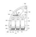
図2は、本開示の一実施形態に係る、輸送体104の内部キャビン104の一部の内部図である。図示するように、3つの座席108は一列にあり得る。分配ノズル106は各座席108の上方に配置される。さらに、還流空気グリル110は各座席108のクッション114の下方に配置される。気流112は、矢印Aで示されるように、分配ノズル106から座席108(及び座席108にいる乗客)の上方及び周りに下向きに、還流空気グリル110へと流れる。
FIG. 2 is an internal view of a part of the
少なくとも1つの実施形態では、分配ノズル106は、アウトボードで収納棚アセンブリ202の下方にある乗客サービスユニット(PSU)200の一部であり、乗客サービスユニット(PSU)200に接続されるか、あるいはその他の方法で乗客サービスユニット(PSU)200に近接している(例えば、6インチ未満内に取り付けられる)。さらに、還流空気グリル110は、空気路208を通って、内部キャビン102の床210に近接した側壁206に固定されるなど側部還流空気グリル204に流体連結している。座席108と関連した還流空気グリル110によって受け入れられた空気は、側部還流空気グリル204の中に引き寄せられ、次いで、低圧によって、内部キャビン104の床210の下にあり得る流出弁120及び/又は空気濾過サブシステム122の中に引き寄せられ得る。任意選択的に、還流空気グリル110は、側部還流空気グリル204と流体連通せずに、流出弁120及び/又は空気濾過サブシステム122に直接連結され得る。
In at least one embodiment, the
少なくとも1つの実施形態では、分配ノズル106はPSU200の一部である。例えば、分配ノズル106は空気ノズル、出口、又はPSU200のようなものである。少なくとも1つの他の実施形態では、分配ノズル106はPSU200とは別個である。例えば、分配ノズル106はギャスパー空気源の一部であり得る。
In at least one embodiment, the
少なくとも1つの実施形態では、複数の分配ノズル106は各座席108と関連している。例えば、4から10の分配ノズル106が各座席108と関連している。代替的に、単一の分配ノズル106は各座席108と関連している。幾つかの実施例では、一以上の分配ノズル106は、一以上の座席の前、座席にいる乗客の前、乗客の横などに向けられたエアカーテンを下向きに向けるように構成される。例えば、分配ノズル106は、エアカーテンがキャビンの空気及び座席108にいる乗客による呼気を取り込むように、還流空気グリル110の方へ向けられ、次いでエアカーテンは還流空気グリル110へ流れる。
In at least one embodiment, the plurality of
図3は、本開示の一実施形態に係る、分配ノズル106が乗客214の上に配置される内部キャビン104の一部の簡略内部図である。非限定的な一実施例として、分配ノズル106は、PSU200のプレナム218内に取り付けられた一以上のギャスパー昇圧ファン216に連結される。
FIG. 3 is a simplified internal view of a portion of the
空気分配サブシステム116(図1に示される)からの新鮮な空気221は、空気分配ダクト220を介してギャスパー昇圧ファン216に供給される。新鮮な空気221は、空気分配ダクト220の出口222から出て、例えばギャスパー昇圧ファン216を介して、PSU200の入口224の中へ引き寄せられる。本明細に記載のように、次いで、ギャスパー昇圧ファン216は、分配ノズル106を介して、乗客214の上及び還流空気グリル110の方へ、気流112として新鮮な空気221を出力する(図1及び図2に示される)。幾つかの実施例では、一般のキャビン空気は、ギャスパー昇圧ファン216によってPSU200の中へ引き寄せられ、PSU200内のHEPAフィルタを通って進み、次いで分配ノズル106から還流空気グリルの方へ排気される。
図4は、本開示の一実施形態に係る、図3のPSU200の上面斜視図である。図5は、図4の乗客サービスユニット200の上面図である。図3~図5を参照すると、一以上のファン230及び/又はフィルタ232(例えばHEPAフィルタ)は、プレナム218内に配置され得る。PSU200には複数の入口224が形成され得る。PSU200には出口234が形成される。分配ノズル106は出口234の中へ及び/又は出口234を通って延伸する。
FIG. 4 is a top perspective view of the
PSU200は、複数の分配ノズル106を含み得る。例えば、PSU200は、少なくとも3つの分配ノズル106を含み得る。
The
図3~図5は、PSU200の一部としての分配ノズル106の非限定的な実施例を示す。かかるものは一例にすぎないことを理解されたい。PSU200は、図示されているよりも多数又は少数の分配ノズル106を含み得る。さらに、分配ノズル106は図示されているのと異なって配置され得る。幾つかの実施形態では、分配ノズル106は、PSU200から分離され、別個であり得る。すなわち、本明細書に記載のように、PSU200は分配ノズル106を含まなくてもよい。さらに、分配ノズル106は、ギャスパー昇圧ファンに直接又は間接的に連結されてもよいし、連結されなくてもよい。
3-5 show non-limiting examples of the
図6は、本開示の一実施形態に係る、内部キャビン104内の座席108にいる乗客214の斜視図である。図示するように、還流空気グリル110はクッション114の下方の内部キャビン104の床210の上(及び/又は中に)取り付けられている。少なくとも1つの実施形態では、還流空気グリル110は各座席108のクッション114の下方にある。
FIG. 6 is a perspective view of a
図7は、本開示の一実施形態に係る、座席108のクッション114の下に固定された還流空気グリル110の斜視図である。少なくとも1つの実施形態では、還流空気グリル110は、複数の入口通路246を有するパネル244を保持する外周フレーム242を有するハウジング240を含む。気流212は、入口通路246を通じて還流空気グリル110の中へ引き寄せられる。還流空気グリル110は、受け入れられた気流112のバランスを取るために、内部バッフルを含み得る。還流空気グリル110は、床210に支持されるマットであり得る。任意選択的に、還流空気グリル110は床210の中に、少なくとも部分的にくぼみを作り得る。
FIG. 7 is a perspective view of the recirculated
少なくとも1つの実施形態では、還流空気グリル110は座席108のシートトラックフィッティングにくっ付いている。シートトラックフィッティングは、内部キャビン104内で座席をシートトラックに固定する。任意選択的に、還流空気グリル110はシートトラックフィッティングにくっ付いていない。例えば、還流空気グリル110は、(例えば分離した別個のファスナ、接着剤などを介して)床210に直接固定され得る。幾つかの実施例では、還流空気グリル110は、床210と一体的に形成され得る。
In at least one embodiment, the recirculated
少なくとも1つの実施形態では、還流空気グリル110は、導管208を介して側部還流空気グリル204に連結される(図2に示される)。一例としては、空気路208は、可撓性ホース、チューブなどであるか、あるいはその他の方法でそれらを含み得る。
In at least one embodiment, the recirculated
図6及び図7を参照すると、還流空気グリル110は床210と平行である。例えば、還流空気グリル110は内部キャビン104に対して水平に向いている。任意選択的に、還流空気グリル110は様々な方向に向き得る。
Referring to FIGS. 6 and 7, the recirculated
図8は、本開示の一実施形態に係る、座席108の簡略側方図である。この実施形態では、還流空気グリル110はクッション114の下方にあるが、床210に対して直角である。例えば、還流空気グリル110は、(例えば内部キャビン104に対して垂直に向くなど)床に対して直立している。少なくとも1つの実施形態では、還流空気グリル110は、(例えば床210上に座席108を支持する脚部の一以上の部分などの)座席108の少なくとも一部に取り付けられている。図示するように、還流空気グリル110はクッション114の下方に配置され、座っている乗客214のふくらはぎ215の後ろにあるように構成され得る。
FIG. 8 is a simplified side view of the
図9は、本開示の一実施形態に係る、輸送体104の内部キャビン104の一部の内部図である。この実施形態では、一以上の座席108の真上にある分配ノズル106に加えて、一以上の分配ノズル106は内部キャビン104内の通路250の上方にもある。例えば、追加の分配ノズル106は、内部キャビン104内の中心線天井位置にある。分配ノズル106は、例えば分配ノズル106の真下にいない可能性のあるインボードの乗客に、追加の気流112を提供する。
FIG. 9 is an internal view of a part of the
図10は、本開示の一実施形態に係る、輸送体104の内部キャビン104の一部の内部図である。少なくとも1つの実施例では、内部キャビン104は、座席108の第1のアウトボードグループ108a、座席108の中央のグループ108b、及び座席108の第2のアウトボードグループ108cを含む。第1のアウトボードグループ108aは、第1の通路250aによって、中央のグループ108bから分離され、第2のアウトボードグループ108cは、第2の通路250bによって、中央のグループ108bから分離される。
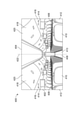
FIG. 10 is an internal view of a part of the
一例としては、座席108の中央のグループ108bは、フィルタ262(例えばHEPAフィルタ)及びファン264を有する床に取り付けられた(又は座席に取り付けられた)プレナム260を含む。空気はファン264によってプレナム260の中へ引き寄せられ、フィルタ262を通って送られ、床210に近接した通路250a及び250bに排出される。本明細書に記載のように、第1のアウトボードグループ108a及び第2のアウトボードグループ108cの床に取り付けられたプレナム270は、プレナム260から排出された空気を引き寄せ、引き寄せられた空気を側部還流空気グリル204(図2に示される)、還流空気グリル110などに送る。
図1~図10を参照すると、本開示の実施形態は、内部キャビン104内の乗客の上の気流112(例えば、円滑で層状の気流)を生成するためのシステム及び方法を提供する。気流112は、乗客の上方の分配ノズル106から、乗客の少なくとも一部の下方に配置された還流空気グリル110の方へ、及び還流空気グリル110の中にトップダウン方向に流れる。円滑で層状の流れは、乗客が呼吸するのに新鮮で清浄な空気を提供し、それと共に、また、呼気を還流空気グリル110の中へ引き寄せ、それにより、(空気の乱れた循環と対照的に)呼気が内部キャビン104内に残る可能性を防止し、最小化し、あるいはその他の方法で低減する。
As an example, the
Referring to FIGS. 1-10, embodiments of the present disclosure provide systems and methods for generating airflow 112 (eg, smooth, layered airflow) over passengers in an
図11は、本開示の一実施形態に係る、航空機310の正面斜視図である。航空機310は、図1に示される輸送体104の一例である。
FIG. 11 is a front perspective view of the
航空機310は、例えば、エンジン314を含む推進システム312を含む。任意選択的に、推進システム312は、図示されているよりも多くのエンジン314を含み得る。エンジン314は、航空機310の翼316によって坦持される。他の実施形態では、エンジン314が、胴体318及び/又は尾部320によって担持され得る。尾部320は、水平安定板322及び垂直安定板324も支持し得る。
航空機310の胴体318は内部キャビン330を画定し、該キャビンは、フライトデッキ、又はコックピット、一以上の作業区域(例えば、ギャレー、乗務員の手荷物エリアなど)、一以上の乗客区域(例えば、ファーストクラス、ビジネスクラス、及びコーチ区域)、一以上のトイレなどを含む。
The
代替的に、本開示の実施形態が、航空機に代わり、自動車、バス、機関車及び列車、船舶などの様々な他の輸送体で使用され得る。さらに、本開示の実施形態は、商業用及び住居用の建物など(例えば、劇場、コンサート会場、講堂、教室、スタジアム、食料品店、オフィスビル、病院など)の固定構造体に対して使用され得る。 Alternatively, embodiments of the present disclosure may be used in place of aircraft in a variety of other transporters such as automobiles, buses, locomotives and trains, ships and the like. Further, embodiments of the present disclosure are used for fixed structures such as commercial and residential buildings (eg, theaters, concert venues, auditoriums, classrooms, stadiums, grocery stores, office buildings, hospitals, etc.). obtain.
図12Aは、本開示の一実施形態に係る、航空機の内部キャビン330の上面図である。内部キャビン330は、図11の胴体318などの、航空機の胴体332内にあり得る。例えば、一以上の胴体壁は、内部キャビン330を画定し得る。内部キャビン330には、前方区域333、ファーストクラス区域334、ビジネスクラス区域336、前方ギャレー局338、拡張されたエコノミー又はコーチ区域340、基準コーチのエコノミー区域342、及び複数のトイレとギャレー局とを含み得る後方区域344を含む、複数の区域が含まれる。内部キャビン330には、図示されているよりも多数又は少数の区域が含まれ得ることを理解されたい。例えば、内部キャビン330は、ファーストクラス区域を含まなくてもよく、図示されているよりも多数又は少数のギャレー局を含み得る。それぞれの区域は、通路348間にクラス仕切アセンブリを含み得る、キャビン移行エリア346によって分離され得る。
FIG. 12A is a top view of the
図12Aに示すように、内部キャビン330は、後方区域344につながる2つの通路350及び352を含む。任意選択的に、内部キャビン330は、図示されているよりも少数又は多数の通路を有し得る。例えば、内部キャビン330は、後方区域344につながる内部キャビン330の中央を通って延伸する単一の通路を含み得る。
As shown in FIG. 12A, the
通路348、350及び352は出口経路又はドア通路360へと延伸する。出口ドア362は出口経路360の端部に位置する。出口経路360は、通路348、350及び352に対して垂直であり得る。内部キャビン330は、様々な場所において図示されているよりも多数の出口経路360を含み得る。図1~図10に対して示し、記載された換気システム100は、内部キャビン330内で使用されるように構成される。
図12Bは、本開示の一実施形態に係る、航空機の内部キャビン380の上面図である。内部キャビン380は、図11に示す内部キャビン330の一例である。内部キャビン380は、航空機の胴体381内にあり得る。例えば、一以上の胴体壁は、内部キャビン380を画定し得る。内部キャビン380は、乗客席383を有するメインキャビン382と、メインキャビン382の後ろの後方区域385とを含む、複数の区域を含む。内部キャビン380には、図示されているよりも多数又は少数の区域が含まれ得ることを理解されたい。
FIG. 12B is a top view of the
内部キャビン380には、後方区域385につながる単一の通路384が含まれ得る。単一の通路384は、後方区域385につながる内部キャビン380の中央を通って延伸し得る。例えば、単一の通路384は、内部キャビン380の中央縦断面の同軸になるように位置合わせされ得る。
The
通路384は、出口経路又はドア通路390へと延伸する。出口ドア392は、出口経路390の端部に位置する。出口経路390は、通路384に対して垂直であり得る。内部キャビン380は、図示されているよりも多数の出口経路を含み得る。図1~図10に対して示し、記載された換気システム100は、内部キャビン380内で使用されるように構成される。
The
図13は、本開示の一実施例に係る、航空機の内部キャビン400の内部斜視図である。内部キャビン400は、天井404に接続されたアウトボード壁402を含む。アウトボード壁402内に、窓406が形成され得る。フロア408が、座席410の列を支持する。図13に示すように、列412は、通路413のどちら側にも2つの座席410を含み得る。しかし、列412は、図示されているよりも多数又は少数の座席410を含み得る。さらに、内部キャビン400は、図示されているよりも多数の通路を含み得る。
FIG. 13 is an internal perspective view of the
通路413のどちら側にも、アウトボード壁402と天井404との間にPSU414が固定されている。PSU414は、内部キャビン400の前端と後端との間に延在する。例えば、PSU414は、列412内で各座席410の上方に位置し得る。各PSU414は、概して、通気孔、読書灯、酸素バッグ降下パネル、乗務員呼出ボタン、及び他のかかる制御装置を含むハウジング416を、列412内の各座席410(又は座席の群)の上方に含み得る。
A
頭上収納棚アセンブリ418は、天井404及び/又はアウトボード壁402に、通路413の両側のPSU414から上方かつインボード側に、固定されている。頭上収納棚アセンブリ418は、座席410の上方で固定されている。頭上収納棚アセンブリ418は、内部キャビン400の前端と後端との間に延在する。各収納棚アセンブリ418は、ストロングバック(図24では隠れていて見えない)に枢動可能に固定された、ピボットビン又はピボットバケット420を含み得る。頭上収納棚アセンブリ418は、PSU414の下面の上方かつインボード側に位置し得る。頭上収納棚アセンブリ418は、例えば乗客の機内持込手荷物や携行品を受け入れるために、枢動して開くように構成される。
The overhead
本明細書で使用される場合、「アウトボード」という用語は、別の構成要素と比較して、内部キャビン400の中央縦断面422からさらに離れた位置を意味する。用語「インボード」は、別の構成要素と比較して、内部キャビン400の中央縦断面422により近い位置を意味する。例えば、PSU414の下面は、収納棚アセンブリ418に対してアウトボードにあり得る。
As used herein, the term "outboard" means a location further away from the central
図1~図10に対して示し、記載された換気システム100は、内部キャビン400内で使用されるように構成される。
The
図14は、本開示の一実施形態に係る、輸送体の内部キャビンなどの、内部空間のための換気方法のフロー図である。本方法は、500において、一以上の分配ノズルを内部空間内の座席と関連付けることと、502において、還流空気グリルを座席と関連付けることと、504において、一以上の分配ノズルからの気流を還流空気グリルの方へ、及び還流空気グリルの中へ向けることとを含む。 FIG. 14 is a flow chart of a ventilation method for an internal space such as an internal cabin of a transporter according to an embodiment of the present disclosure. The method associates one or more distribution nozzles with a seat in the internal space at 500, associates a recirculated air grill with a seat at 502, and recirculates airflow from one or more distribution nozzles at 504. Includes pointing towards the grill and into the recirculated air grill.
少なくとも1つの実施例では、一以上の分配ノズルを前記関連付けることは、座席の上方に一以上の分配ノズルを配置することを含む。さらに、少なくとも1つの実施例では、還流空気グリルを前記関連付けることは、座席の少なくとも一部の下方に還流空気グリルを配置することを含む。 In at least one embodiment, the association of one or more distribution nozzles comprises placing one or more distribution nozzles above the seat. Further, in at least one embodiment, the association of the recirculated air grill comprises placing the recirculated air grill below at least a portion of the seat.
少なくとも1つの実施例では、本方法は、空気分配サブシステムによって、清浄な空気を一以上の分配ノズルに提供することも含む。 In at least one embodiment, the method also comprises providing clean air to one or more distribution nozzles by means of an air distribution subsystem.
少なくとも1つの実施例では、本方法は、一以上の流出弁を還流空気グリルに流体連結させることも含む。 In at least one embodiment, the method also comprises fluidly coupling one or more outflow valves to a reflux air grill.
少なくとも1つの実施例では、本方法は、空気濾過サブシステムを還流空気グリルに流体連結させることも含む。 In at least one embodiment, the method also comprises fluid-connecting an air filtration subsystem to a recirculated air grill.
少なくとも1つの実施例では、本方法は、内部空間の側壁の片側若しくは両側、又は床に側部還流空気グリルを固定することと、側部還流空気グリルに還流空気グリルを流体連結させることも含む。 In at least one embodiment, the method also comprises fixing the side recirculated air grill to one or both sides of the side wall of the interior space, or to the floor, and fluidly connecting the recirculated air grill to the side recirculated air grill. ..
さらなる例としては、本方法は、内部空間の床に還流空気グリルを固定することを含む。幾つかの実施例では、本方法は、座席の一部に還流空気グリルを固定することを含む。 As a further example, the method comprises fixing a recirculated air grill to the floor of the interior space. In some embodiments, the method comprises fixing a recirculated air grill to a portion of the seat.
少なくとも1つの実施形態では、本方法は、内部空間内に、一以上の追加の分配ノズルを提供することも含む。 In at least one embodiment, the method also includes providing one or more additional distribution nozzles within the interior space.
少なくとも1つの実施形態では、本方法は、フィルタ及びファンを有するプレナムを内部空間の床に取り付けることをさらに含む。 In at least one embodiment, the method further comprises mounting a plenum with a filter and a fan on the floor of the interior space.
本明細書に記載のように、本開示の実施形態は、フライトの間、航空機の内部キャビンにおける乗客間などの、旅行中の輸送体に乗った乗客間の病原体の広がりを、乗客に害を与えるリスクを伴わずに、防止し、最小化し、あるいはその他の方法で低減するためのシステム及び方法を提供する。 As described herein, embodiments of the present disclosure harm passengers the spread of pathogens between passengers aboard a traveling transport, such as during a flight, between passengers in an aircraft's internal cabin, and so on. Provide systems and methods for preventing, minimizing, or otherwise mitigating without risk.
さらに、本開示は以下の条項による実施形態を含む。 In addition, the disclosure includes embodiments under the following provisions.
条項1. 内部空間内の座席と関連した一以上の分配ノズルと、
前記座席と関連した還流空気グリルと、
を備えるシステムであって、
気流が前記一以上の分配ノズルから、前記還流空気グリルの方へ、及び前記還流空気グリルの中へ向けられる、システム。
Clause 1. With one or more distribution nozzles associated with seats in the interior space,
With the recirculated air grill associated with the seat,
It is a system equipped with
A system in which airflow is directed from the one or more distribution nozzles towards the recirculated air grill and into the recirculated air grill.
条項2.前記一以上の分配ノズルが前記座席の上方にあり、前記還流空気グリルが前記座席の少なくとも一部の下方にある、条項1に記載のシステム。 Clause 2. The system according to clause 1, wherein the one or more distribution nozzles are above the seat and the recirculated air grill is below at least a portion of the seat.
条項3.前記座席の前記少なくとも一部が、乗客が座るクッションを含む、条項2に記載のシステム。 Clause 3. The system according to clause 2, wherein at least a portion of the seat comprises a cushion on which a passenger sits.
条項4.前記一以上の分配ノズルが少なくとも5つの分配ノズルを含む、条項1から3のいずれか一項に記載のシステム。 Clause 4. The system according to any one of clauses 1 to 3, wherein the one or more distribution nozzles include at least five distribution nozzles.
条項5.前記一以上の分配ノズルに清浄な空気を提供する空気分配サブシステムをさらに備える、条項1から4のいずれか一項に記載のシステム。 Clause 5. The system according to any one of clauses 1 to 4, further comprising an air distribution subsystem that provides clean air to the one or more distribution nozzles.
条項6.前記還流空気グリルに流体連結された一以上の流出弁をさらに備える、条項1から5のいずれか一項に記載のシステム。 Clause 6. The system according to any one of clauses 1 to 5, further comprising one or more outflow valves fluidly coupled to the reflux air grill.
条項7.前記還流空気グリルに流体連結された空気濾過サブシステムをさらに備える、条項1から6のいずれか一項に記載のシステム。 Clause 7. The system according to any one of clauses 1 to 6, further comprising an air filtration subsystem fluidly coupled to the reflux air grill.
条項8.前記一以上の分配ノズルが、輸送体の内部キャビン内の乗客サービスユニットの一部である、条項1から7のいずれか一項に記載のシステム。
条項9.前記内部空間の側壁の片側若しくは両側、又は床に固定された側部還流空気グリルをさらに備え、前記還流空気グリルが前記側部還流空気グリルに流体連結している、条項1から8のいずれか一項に記載のシステム。 Clause 9. Any of clauses 1-8, further comprising a side recirculated air grill fixed to one or both sides of the side wall of the internal space, or to the floor, wherein the recirculated air grill is fluidly coupled to the side recirculated air grill. The system described in paragraph 1.
条項10.前記還流空気グリルが前記内部空間の床に固定されている、条項1から9のいずれか一項に記載のシステム。
条項11.前記還流空気グリルが前記座席の一部に固定されている、条項1から10のいずれか一項に記載のシステム。 Clause 11. The system according to any one of clauses 1 to 10, wherein the recirculated air grill is fixed to a part of the seat.
条項12.前記内部空間内に一以上の追加の分配ノズルをさらに備える、条項1から11のいずれか一項に記載のシステム。 Clause 12. The system according to any one of clauses 1 to 11, further comprising one or more additional distribution nozzles in the interior space.
条項13.前記内部空間の床に取り付けられたプレナムをさらに備え、前記プレナムがフィルタ及びファンを含む、条項1から12のいずれか一項に記載のシステム。 Clause 13. The system of any one of clauses 1-12, further comprising a plenum mounted on the floor of the interior space, wherein the plenum comprises a filter and a fan.
条項14. 一以上の分配ノズルを内部空間内の座席と関連付けることと、
還流空気グリルを前記座席と関連付けることと、
前記一以上の分配ノズルからの気流を前記還流空気グリルの方へ、及び前記還流空気グリルの中へ向けることと、
を含む、方法。
Clause 14. To associate one or more distribution nozzles with seats in the interior space,
To associate the recirculated air grill with the seat
Directing the airflow from the one or more distribution nozzles toward the recirculated air grill and into the recirculated air grill.
Including the method.
条項15.前記一以上の分配ノズルを前記関連付けることが、前記一以上の分配ノズルを前記座席の上方に配置することを含み、前記還流空気グリルを前記関連付けることが、前記還流空気グリルを前記座席の少なくとも一部の下方に配置することを含む、条項14に記載の方法。 Clause 15. The association of the one or more distribution nozzles comprises placing the one or more distribution nozzles above the seat, and the association of the recirculated air grill comprises at least one of the recirculation air grills of the seat. The method of clause 14, comprising placing below the section.
条項16.前記座席の前記少なくとも一部が、乗客が座るクッションを含む、条項15に記載の方法。 Clause 16. 25. The method of clause 15, wherein at least a portion of the seat comprises a cushion on which a passenger sits.
条項17.空気分配サブシステムによって、前記一以上の分配ノズルに清浄な空気を提供することをさらに含む、条項14から16のいずれか一項に記載の方法。 Clause 17. The method of any one of clauses 14-16, further comprising providing clean air to the one or more distribution nozzles by means of an air distribution subsystem.
条項18.前記還流空気グリルに一以上の流出弁を流体連結することをさらに含む、条項14から17のいずれか一項に記載の方法。 Clause 18. The method of any one of clauses 14-17, further comprising fluid-connecting one or more outflow valves to the reflux air grill.
条項19.前記還流空気グリルに空気濾過サブシステムを流体連結することをさらに含む、条項14から18のいずれか一項に記載の方法。 Clause 19. 28. The method of any one of clauses 14-18, further comprising fluid-connecting an air filtration subsystem to the reflux air grill.
条項20.前記内部空間の側壁の片側若しくは両側、又は床に側部還流空気グリルを固定することと、前記還流空気グリルを前記側部還流空気グリルに流体連結することとをさらに含む、条項14から19のいずれか一項に記載の方法。 Clause 20. Clause 14-19, further comprising fixing the side return air grill to one or both sides of the side wall of the internal space, or to the floor, and fluidly connecting the return air grill to the side return air grill. The method described in any one of the items.
条項21.前記還流空気グリルを前記内部空間の床に固定することをさらに含む、条項14から20のいずれか一項に記載の方法。 Clause 21. The method of any one of clauses 14-20, further comprising fixing the recirculated air grill to the floor of the interior space.
条項22.前記還流空気グリルを前記座席の一部に固定することをさらに含む、条項14から21のいずれか一項に記載の方法。 Clause 22. 28. The method of any one of clauses 14-21, further comprising fixing the recirculated air grill to a portion of the seat.
条項23.前記内部空間内に一以上の追加の分配ノズルを提供することをさらに含む、条項14から22のいずれか一項に記載の方法。 Clause 23. The method of any one of clauses 14-22, further comprising providing one or more additional distribution nozzles in the interior space.
条項24.フィルタ及びファンを有するプレナムを前記内部空間の床に取り付けることをさらに含む、条項14から23のいずれか一項に記載の方法。 Clause 24. The method of any one of clauses 14-23, further comprising attaching a plenum having a filter and a fan to the floor of the interior space.
条項25. 内部キャビンと、
前記内部キャビン内の複数の座席と、
一以上の分配ノズル及び前記複数の座席のそれぞれと関連した還流空気グリルを備えた換気システムと、
を備える輸送体であって、気流が前記一以上の分配ノズルから、前記還流空気グリルの方へ、及び前記還流空気グリルの中へ向けられる、輸送体。
Clause 25. With the internal cabin,
With multiple seats in the internal cabin,
A ventilation system with one or more distribution nozzles and a perfusion air grill associated with each of the multiple seats.
A transporter comprising:, wherein the airflow is directed from the one or more distribution nozzles toward the recirculated air grill and into the recirculated air grill.
本開示の実施形態の説明のために、上部、底部、下方、中央、横方向、水平、垂直、前方などの空間及び方向に関する様々な用語が使用される場合があるが、かかる用語は図面中で示す向きに関するものとして使用されているにすぎないことが理解される。これらの向きは、上部が下部になる、その逆、水平が垂直になるなどのように、反転、回転、あるいはその他の方法で変更され得る。 Various terms relating to space and orientation, such as top, bottom, bottom, center, lateral, horizontal, vertical, forward, etc., may be used for the purposes of the embodiments of the present disclosure, although such terms are in the drawings. It is understood that it is only used as a reference for the orientation shown in. These orientations can be flipped, rotated, or otherwise changed, such as top to bottom, vice versa, horizontal to vertical, and so on.
本明細書で使用される場合、タスク又は動作を実行する「よう構成/設定され(configured to)」ている構造体、制約、又は要素は、タスク又は動作に対応する様態で、特に構造的に、形成され、構成/設定され、又は適合している。分かりやすくするため、かつ誤解を避けるために、タスク又は動作を実行するために改変されることが可能であるだけの対象物は、本明細書における、タスク又は動作を実行する「よう構成/設定」されているものではない。 As used herein, a structure, constraint, or element that is "configured to" perform a task or action, in a manner that corresponds to the task or action, in particular structurally. , Formed, configured / set, or adapted. Objects that can only be modified to perform a task or action, for clarity and to avoid misunderstandings, are "configured / configured" herein to perform the task or action. It is not something that has been done.
上記の説明は、限定ではなく例示を意図するものであると理解されたい。例えば、上述した実施形態(及び/又はそれらの態様)は、互いに組み合わせて使用され得る。加えて、本開示の様々な実施形態の教示には、それらの範囲から逸脱することなく、特定の状況又は材料に適合させるために多数の改変が行われ得る。本明細書に記載の材料の寸法及び種類は、本開示の様々な実施形態のパラメータを規定することを意図しているが、これらの実施形態は決して限定的なものではなく、例示的な実施形態である。上述の説明を精査することにより、当業者には他の多くの実施形態が明らかであろう。したがって、本開示の様々な実施形態の範囲は、添付の特許請求の範囲とともに、かかる特許請求の範囲が権利を有する均等物の全範囲を参照して決定されるべきである。添付の特許請求の範囲及び本明細書における発明を実施するための形態において、「含む(including)及び(containing)」という用語は、「備える(comprising)」という用語の明白な同義語として使用され、「これにおいて(in which)」という用語は、「ここで(wherein)」という用語の明白な同義語として使用される。さらに、「第1の」、「第2の」及び「第3の」等の用語は、単にラベルとして使用されており、それらの対象物に数的要件を課すことを意図するものではない。 It should be understood that the above description is intended to be exemplary rather than limiting. For example, the embodiments described above (and / or aspects thereof) may be used in combination with each other. In addition, the teachings of the various embodiments of the present disclosure may be modified in a number of ways to adapt to a particular situation or material without departing from their scope. The dimensions and types of materials described herein are intended to specify the parameters of the various embodiments of the present disclosure, but these embodiments are by no means limiting and exemplary. It is a form. By scrutinizing the above description, many other embodiments will be apparent to those of skill in the art. Therefore, the scope of the various embodiments of the present disclosure should be determined with reference to the scope of the appended claims, as well as the entire scope of the equivalents to which the claims are entitled. In the appended claims and in the form for carrying out the invention herein, the terms "inclusion and connecting" are used as explicit synonyms for the term "comprising". , The term "in which" is used as an explicit synonym for the term "herein". Moreover, terms such as "first," "second," and "third" are used merely as labels and are not intended to impose numerical requirements on those objects.
ここに記載した説明では、ベストモードを含む本開示の様々な実施形態を開示し、かつ当業者が任意のデバイス又はシステムの作成及び使用、並びに組み込まれた任意の方法の実行を含め、本開示の様々な実施形態を実施することを可能にするために実施例を使用している。本開示の様々な実施形態の特許性の範囲は、特許請求の範囲によって規定されるものであり、当業者が想起する他の実施例を含み得る。かかる他の実施例は、それらが特許請求の範囲の文言と相違しない構造要素を有する場合、又はそれらが特許請求の範囲の文言とのごくわずかな相違しか有さない同等の構造要素を含む場合には、特許請求の範囲に含まれることが意図されている。
The description herein discloses various embodiments of the present disclosure, including the best mode, and the present disclosure includes the creation and use of any device or system by one of ordinary skill in the art, as well as the execution of any incorporated method. The embodiments are used to make it possible to implement various embodiments of. The scope of patentability of the various embodiments of the present disclosure is defined by the claims and may include other embodiments recalled by those of skill in the art. Such other embodiments include when they have structural elements that do not differ from the wording of the claims, or when they contain equivalent structural elements that have only slight differences from the wording of the claims. Is intended to be included in the claims.
Claims (15)
前記座席(108)と関連した還流空気グリル(110)と、
を備えるシステム(100)であって、
気流(112)が前記一以上の分配ノズル(106)から、前記還流空気グリル(110)の方へ、及び前記還流空気グリル(110)の中へ向けられる、システム(100)。 With one or more distribution nozzles (106) associated with the seat (108) in the interior space,
With the recirculated air grill (110) associated with the seat (108),
A system (100) equipped with
A system (100) in which airflow (112) is directed from the one or more distribution nozzles (106) toward the recirculated air grill (110) and into the recirculated air grill (110).
前記還流空気グリル(110)に流体連結された一以上の流出弁(120)、又は、
前記還流空気グリル(110)に流体連結された空気濾過サブシステム(122)
のうちの少なくとも1つをさらに備える、請求項1から3のいずれか一項に記載のシステム(100)。 An air distribution subsystem (116), which provides clean air to one or more distribution nozzles (106).
One or more outflow valves (120) fluidly coupled to the reflux air grill (110), or
An air filtration subsystem (122) fluid-coupled to the reflux air grill (110).
The system (100) according to any one of claims 1 to 3, further comprising at least one of.
還流空気グリル(110)を前記座席(108)と関連付けることと、
前記一以上の分配ノズル(106)からの気流(112)を前記還流空気グリル(110)の方へ、及び前記還流空気グリル(110)の中へ向けることと、
を含む、方法。 To associate one or more distribution nozzles (106) with a seat (108) in an interior space,
Associating the recirculated air grill (110) with the seat (108)
Directing the airflow (112) from the one or more distribution nozzles (106) toward the recirculated air grill (110) and into the recirculated air grill (110).
Including the method.
フィルタ及びファンを有するプレナムを前記内部空間の床(210)に取り付けること
のうちの少なくとも1つをさらに含む、請求項10から14のいずれか一項に記載の方法。
Claimed to further include at least one of providing one or more additional distribution nozzles (106) in the interior space, or mounting a plenum with a filter and a fan on the floor (210) of the interior space. Item 10. The method according to any one of Items 10 to 14.
Applications Claiming Priority (2)
| Application Number | Priority Date | Filing Date | Title |
|---|---|---|---|
| US202063071466P | 2020-08-28 | 2020-08-28 | |
| US63/071,466 | 2020-08-28 |
Publications (1)
| Publication Number | Publication Date |
|---|---|
| JP2022040109A true JP2022040109A (en) | 2022-03-10 |
Family
ID=80440985
Family Applications (1)
| Application Number | Title | Priority Date | Filing Date |
|---|---|---|---|
| JP2021139477A Pending JP2022040109A (en) | 2020-08-28 | 2021-08-28 | Ventilation systems and methods for internal cabins of vehicles |
Country Status (2)
| Country | Link |
|---|---|
| JP (1) | JP2022040109A (en) |
| CN (1) | CN114104295A (en) |
-
2021
- 2021-08-10 CN CN202110912276.7A patent/CN114104295A/en active Pending
- 2021-08-28 JP JP2021139477A patent/JP2022040109A/en active Pending
Also Published As
| Publication number | Publication date |
|---|---|
| CN114104295A (en) | 2022-03-01 |
Similar Documents
| Publication | Publication Date | Title |
|---|---|---|
| US10029797B2 (en) | Personal ventilation in an aircraft environment | |
| JP2678168B2 (en) | Ventilation system and method of removing contaminated air | |
| US20100081369A1 (en) | Personal ventilation in an aircraft environment | |
| US5784836A (en) | Demountable comfort modules for passenger aircraft | |
| EP2851298A1 (en) | Air diffuser systems, methods, and apparatuses | |
| US11590442B2 (en) | Systems and methods for providing filtered air to an enclosure for a passenger of a vehicle | |
| US20090017742A1 (en) | Ionized-re-circulating air-aircraft | |
| US11337404B2 (en) | Vehicle, ventilation system, and method for transporting pets | |
| US20210387731A1 (en) | Personal aircraft seat air treatment system | |
| EP3960629A1 (en) | Ventilation systems and methods for internal cabins of vehicles | |
| US20220135235A1 (en) | Ventilation systems and methods for internal cabins of vehicles | |
| JP2022040109A (en) | Ventilation systems and methods for internal cabins of vehicles | |
| EP3960630B1 (en) | Air curtain systems and methods for vehicle cabins | |
| US20220001993A1 (en) | Air curtain systems and methods for internal cabins of vehicles | |
| EP4112471A1 (en) | Ventilation assembly in an aircraft | |
| EP3954610A1 (en) | Aircraft seats with air vents | |
| EP3988452A1 (en) | Headrest ventilation systems and methods for seating assemblies | |
| CN111361744B (en) | Ventilation system for air supply along aircraft cabin passageway | |
| US20220041288A1 (en) | Aircraft seats with air vents | |
| WO2022015739A1 (en) | Virus filtered/sterilized airflows directed to passengers in vehicle | |
| US11999490B2 (en) | Air curtain systems and methods for vehicle cabins | |
| JP3051854B2 (en) | Smoke separation device and method for separating airflow in passenger room | |
| RU128598U1 (en) | SPECIAL APPLIANCES | |
| EP4149633A1 (en) | Vehicle with a system for protecting passengers and crew members from airborne pathogens | |
| CN114291269A (en) | Negative pressure isolation system for vehicle cabin |