JP2021533633A - Vehicle support system - Google Patents
Vehicle support system Download PDFInfo
- Publication number
- JP2021533633A JP2021533633A JP2021505414A JP2021505414A JP2021533633A JP 2021533633 A JP2021533633 A JP 2021533633A JP 2021505414 A JP2021505414 A JP 2021505414A JP 2021505414 A JP2021505414 A JP 2021505414A JP 2021533633 A JP2021533633 A JP 2021533633A
- Authority
- JP
- Japan
- Prior art keywords
- optical
- selection element
- wavelength band
- filter array
- full
- Prior art date
- Legal status (The legal status is an assumption and is not a legal conclusion. Google has not performed a legal analysis and makes no representation as to the accuracy of the status listed.)
- Withdrawn
Links
- 230000003287 optical effect Effects 0.000 claims abstract description 239
- 238000000034 method Methods 0.000 claims description 22
- 238000004891 communication Methods 0.000 claims description 18
- 230000004044 response Effects 0.000 claims description 12
- 239000012788 optical film Substances 0.000 claims description 11
- 230000003595 spectral effect Effects 0.000 claims description 10
- 230000005540 biological transmission Effects 0.000 claims description 9
- 239000010408 film Substances 0.000 claims description 7
- 238000003384 imaging method Methods 0.000 claims description 5
- 238000009792 diffusion process Methods 0.000 claims description 2
- XLYOFNOQVPJJNP-UHFFFAOYSA-N water Substances O XLYOFNOQVPJJNP-UHFFFAOYSA-N 0.000 claims 1
- 238000010586 diagram Methods 0.000 description 48
- 230000010287 polarization Effects 0.000 description 22
- 238000003491 array Methods 0.000 description 15
- 239000011521 glass Substances 0.000 description 13
- 238000002834 transmittance Methods 0.000 description 10
- 230000006870 function Effects 0.000 description 9
- 238000001228 spectrum Methods 0.000 description 8
- 238000001514 detection method Methods 0.000 description 6
- 230000008901 benefit Effects 0.000 description 5
- 239000011248 coating agent Substances 0.000 description 4
- 238000000576 coating method Methods 0.000 description 4
- 230000000670 limiting effect Effects 0.000 description 4
- 101100248200 Arabidopsis thaliana RGGB gene Proteins 0.000 description 3
- 230000009977 dual effect Effects 0.000 description 3
- 238000012545 processing Methods 0.000 description 3
- 230000000007 visual effect Effects 0.000 description 3
- 206010034960 Photophobia Diseases 0.000 description 2
- 238000004458 analytical method Methods 0.000 description 2
- 238000013459 approach Methods 0.000 description 2
- 230000008859 change Effects 0.000 description 2
- 230000000295 complement effect Effects 0.000 description 2
- 239000002131 composite material Substances 0.000 description 2
- 208000013469 light sensitivity Diseases 0.000 description 2
- 238000010801 machine learning Methods 0.000 description 2
- 230000036961 partial effect Effects 0.000 description 2
- 238000003909 pattern recognition Methods 0.000 description 2
- 230000007704 transition Effects 0.000 description 2
- 230000009471 action Effects 0.000 description 1
- 239000000853 adhesive Substances 0.000 description 1
- 230000001070 adhesive effect Effects 0.000 description 1
- 230000002411 adverse Effects 0.000 description 1
- 230000006399 behavior Effects 0.000 description 1
- 239000003086 colorant Substances 0.000 description 1
- 238000010276 construction Methods 0.000 description 1
- 238000007796 conventional method Methods 0.000 description 1
- 238000013527 convolutional neural network Methods 0.000 description 1
- 238000013136 deep learning model Methods 0.000 description 1
- 238000011161 development Methods 0.000 description 1
- 230000000694 effects Effects 0.000 description 1
- 238000005516 engineering process Methods 0.000 description 1
- 238000001914 filtration Methods 0.000 description 1
- 230000004313 glare Effects 0.000 description 1
- 230000010354 integration Effects 0.000 description 1
- 230000002452 interceptive effect Effects 0.000 description 1
- 238000010030 laminating Methods 0.000 description 1
- 239000000463 material Substances 0.000 description 1
- 238000012544 monitoring process Methods 0.000 description 1
- 229920000642 polymer Polymers 0.000 description 1
- 230000008569 process Effects 0.000 description 1
- 230000002829 reductive effect Effects 0.000 description 1
- 230000001105 regulatory effect Effects 0.000 description 1
- 238000004611 spectroscopical analysis Methods 0.000 description 1
- 230000001360 synchronised effect Effects 0.000 description 1
Images


Classifications
-
- G—PHYSICS
- G06—COMPUTING; CALCULATING OR COUNTING
- G06V—IMAGE OR VIDEO RECOGNITION OR UNDERSTANDING
- G06V10/00—Arrangements for image or video recognition or understanding
- G06V10/10—Image acquisition
- G06V10/12—Details of acquisition arrangements; Constructional details thereof
- G06V10/14—Optical characteristics of the device performing the acquisition or on the illumination arrangements
- G06V10/143—Sensing or illuminating at different wavelengths
-
- G—PHYSICS
- G02—OPTICS
- G02B—OPTICAL ELEMENTS, SYSTEMS OR APPARATUS
- G02B27/00—Optical systems or apparatus not provided for by any of the groups G02B1/00 - G02B26/00, G02B30/00
- G02B27/28—Optical systems or apparatus not provided for by any of the groups G02B1/00 - G02B26/00, G02B30/00 for polarising
- G02B27/288—Filters employing polarising elements, e.g. Lyot or Solc filters
-
- G—PHYSICS
- G02—OPTICS
- G02B—OPTICAL ELEMENTS, SYSTEMS OR APPARATUS
- G02B5/00—Optical elements other than lenses
- G02B5/20—Filters
- G02B5/201—Filters in the form of arrays
-
- G—PHYSICS
- G02—OPTICS
- G02B—OPTICAL ELEMENTS, SYSTEMS OR APPARATUS
- G02B5/00—Optical elements other than lenses
- G02B5/20—Filters
- G02B5/208—Filters for use with infrared or ultraviolet radiation, e.g. for separating visible light from infrared and/or ultraviolet radiation
-
- G—PHYSICS
- G06—COMPUTING; CALCULATING OR COUNTING
- G06V—IMAGE OR VIDEO RECOGNITION OR UNDERSTANDING
- G06V10/00—Arrangements for image or video recognition or understanding
- G06V10/10—Image acquisition
- G06V10/12—Details of acquisition arrangements; Constructional details thereof
- G06V10/14—Optical characteristics of the device performing the acquisition or on the illumination arrangements
- G06V10/147—Details of sensors, e.g. sensor lenses
-
- G—PHYSICS
- G06—COMPUTING; CALCULATING OR COUNTING
- G06V—IMAGE OR VIDEO RECOGNITION OR UNDERSTANDING
- G06V20/00—Scenes; Scene-specific elements
- G06V20/50—Context or environment of the image
- G06V20/56—Context or environment of the image exterior to a vehicle by using sensors mounted on the vehicle
- G06V20/58—Recognition of moving objects or obstacles, e.g. vehicles or pedestrians; Recognition of traffic objects, e.g. traffic signs, traffic lights or roads
- G06V20/582—Recognition of moving objects or obstacles, e.g. vehicles or pedestrians; Recognition of traffic objects, e.g. traffic signs, traffic lights or roads of traffic signs
-
- G—PHYSICS
- G08—SIGNALLING
- G08G—TRAFFIC CONTROL SYSTEMS
- G08G1/00—Traffic control systems for road vehicles
- G08G1/09—Arrangements for giving variable traffic instructions
- G08G1/0962—Arrangements for giving variable traffic instructions having an indicator mounted inside the vehicle, e.g. giving voice messages
- G08G1/09623—Systems involving the acquisition of information from passive traffic signs by means mounted on the vehicle
-
- G—PHYSICS
- G08—SIGNALLING
- G08G—TRAFFIC CONTROL SYSTEMS
- G08G1/00—Traffic control systems for road vehicles
- G08G1/09—Arrangements for giving variable traffic instructions
- G08G1/0962—Arrangements for giving variable traffic instructions having an indicator mounted inside the vehicle, e.g. giving voice messages
- G08G1/0968—Systems involving transmission of navigation instructions to the vehicle
-
- H—ELECTRICITY
- H04—ELECTRIC COMMUNICATION TECHNIQUE
- H04N—PICTORIAL COMMUNICATION, e.g. TELEVISION
- H04N23/00—Cameras or camera modules comprising electronic image sensors; Control thereof
- H04N23/10—Cameras or camera modules comprising electronic image sensors; Control thereof for generating image signals from different wavelengths
- H04N23/11—Cameras or camera modules comprising electronic image sensors; Control thereof for generating image signals from different wavelengths for generating image signals from visible and infrared light wavelengths
-
- H—ELECTRICITY
- H04—ELECTRIC COMMUNICATION TECHNIQUE
- H04N—PICTORIAL COMMUNICATION, e.g. TELEVISION
- H04N23/00—Cameras or camera modules comprising electronic image sensors; Control thereof
- H04N23/10—Cameras or camera modules comprising electronic image sensors; Control thereof for generating image signals from different wavelengths
- H04N23/13—Cameras or camera modules comprising electronic image sensors; Control thereof for generating image signals from different wavelengths with multiple sensors
- H04N23/16—Optical arrangements associated therewith, e.g. for beam-splitting or for colour correction
-
- H—ELECTRICITY
- H04—ELECTRIC COMMUNICATION TECHNIQUE
- H04N—PICTORIAL COMMUNICATION, e.g. TELEVISION
- H04N23/00—Cameras or camera modules comprising electronic image sensors; Control thereof
- H04N23/50—Constructional details
- H04N23/55—Optical parts specially adapted for electronic image sensors; Mounting thereof
-
- H—ELECTRICITY
- H04—ELECTRIC COMMUNICATION TECHNIQUE
- H04N—PICTORIAL COMMUNICATION, e.g. TELEVISION
- H04N23/00—Cameras or camera modules comprising electronic image sensors; Control thereof
- H04N23/57—Mechanical or electrical details of cameras or camera modules specially adapted for being embedded in other devices
-
- H—ELECTRICITY
- H04—ELECTRIC COMMUNICATION TECHNIQUE
- H04N—PICTORIAL COMMUNICATION, e.g. TELEVISION
- H04N7/00—Television systems
- H04N7/18—Closed-circuit television [CCTV] systems, i.e. systems in which the video signal is not broadcast
Abstract
本開示は、光センサと、光センサに隣接するピクセル化フィルタアレイと、ピクセル化フィルタアレイに隣接する全視野光学選択要素と、を含む例示的な車両支援システムについて記述する。光学選択要素は、光学選択要素に入射する光の光学成分を、ピクセル化フィルタアレイを横切って光センサに選択的に誘導するように構成されている。The present disclosure describes an exemplary vehicle assist system including an optical sensor, a pixelated filter array adjacent to the optical sensor, and a full-field optical selection element adjacent to the pixelated filter array. The optical selection element is configured to selectively guide the optical component of light incident on the optical selection element to the photosensor across the pixelated filter array.
Description
本開示は、車両支援システム、特に、光学車両支援システムについて記述する。 The present disclosure describes vehicle assistance systems, in particular optical vehicle assistance systems.
自動運転技術では、光センサシステムを利用して道路上の物体を検知する。物体には、インフラ、他の車両、又は歩行者が含まれ得る。検知性能の範囲の増大、信号対雑音比の向上、及び物体の認識の向上は、発展分野であり続ける。実質的に視覚的には認識できないものの、光センサシステムを介して、誘目性、識別性、及びデータを遠隔で提供することができるシステムは有利であり得る。例えば、標識は2つの目的を果たし得る。つまり、標識は、従来の手法で視覚的に読み取ることができると同時に、搭載運転システムの自動運転を支援する不可視のコードを光学システムにより感知することができる。 Autonomous driving technology uses an optical sensor system to detect objects on the road. Objects can include infrastructure, other vehicles, or pedestrians. Increasing the range of detection performance, improving the signal-to-noise ratio, and improving object recognition continue to be areas of development. Although virtually unrecognizable, a system capable of remotely providing attractiveness, distinctiveness, and data via an optical sensor system can be advantageous. For example, a sign can serve two purposes. That is, the sign can be visually read by conventional methods, and at the same time, the invisible code that supports the automatic driving of the on-board driving system can be sensed by the optical system.
光センサに関する他の業界の課題としては、インフラ、車両、又は歩行者の検知において信号対雑音比の問題を生じさせる可能性のある、光路及び光品質に影響し得る不利な条件での検知を向上させる必要性が挙げられる。 Another industry challenge for optical sensors is detection under adverse conditions that can affect the light path and light quality, which can cause signal-to-noise ratio problems in detecting infrastructure, vehicles, or pedestrians. There is a need to improve.
本開示は、光センサと、光センサに隣接するピクセル化フィルタアレイと、ピクセル化フィルタアレイに隣接する全視野光学選択要素と、を含む例示的な車両支援システムについて記述する。光学選択要素は、光学選択要素に入射する光の光学成分を、ピクセル化フィルタアレイを横切って光センサに選択的に誘導するように構成されている。一部の例では、車両は、陸用車両、海用車両、又は空用車両を含む。 The present disclosure describes an exemplary vehicle assist system including an optical sensor, a pixelated filter array adjacent to the optical sensor, and a full-field optical selection element adjacent to the pixelated filter array. The optical selection element is configured to selectively guide the optical component of light incident on the optical selection element to the photosensor across the pixelated filter array. In some examples, the vehicle includes a land vehicle, a marine vehicle, or an aerial vehicle.
本開示は、車両支援システムの全視野光学選択要素によって、物体から光信号を受信することを含む例示的な手法について記述する。この例示的な手法は、全視野光学選択要素によって、光信号の光学成分を、ピクセル化フィルタアレイを通して光センサに選択的に誘導することを含む。コンピューティングデバイスは、光信号に応じたイメージセンサからの画像データ信号を受信してもよく、画像データ信号をルックアップテーブル内の複数の参照画像と比較してもよく、比較に応じて、出力信号を生成してもよい。 The present disclosure describes an exemplary technique involving receiving an optical signal from an object by means of a vehicle assist system full-field optical selection element. This exemplary technique involves selectively guiding the optical components of an optical signal to an optical sensor through a pixelated filter array by means of a full-field optical selection element. The computing device may receive an image data signal from an image sensor in response to an optical signal, may compare the image data signal to multiple reference images in a lookup table, and output in response to the comparison. A signal may be generated.
本発明の1つ以上の態様の詳細は、添付の図面及び以下の説明に記載されている。本発明の他の特徴、目的、及び利点は、明細書及び図面、並びに特許請求の範囲から明らかになろう。 Details of one or more embodiments of the invention are described in the accompanying drawings and the following description. Other features, objects, and advantages of the invention will become apparent from the specification and drawings, as well as the claims.
以下の「発明を実施するための形態」と、添付の図面を併せて読むことによって、本発明の上記及び他の態様はより明らかになる。 The above and other aspects of the invention will be further clarified by reading the following "forms for carrying out the invention" together with the accompanying drawings.
本開示の特定の図の特徴は必ずしも原寸に比例して描かれているとは限らず、図は、本明細書に開示されている技法の非排他的な実施例を示していることを理解されたい。 It is understood that the features of the particular figures in this disclosure are not necessarily drawn in proportion to their actual size and that the figures represent non-exclusive examples of the techniques disclosed herein. I want to be.
本開示は、車両ナビゲーションシステムについて記述する。一部の例では、本開示による車両ナビゲーションシステムは、光学的に符号化された物品のパターン又は光学的シグネチャ、例えば、ナビゲーション支援又は道路標識パターン若しくは物体を復号するために使用されてもよい。 The present disclosure describes a vehicle navigation system. In some examples, the vehicle navigation system according to the present disclosure may be used to decode an optically coded pattern of goods or an optical signature, such as a navigation aid or a road sign pattern or object.
車両支援システムは、自動運転支援システム(ADAS)を含み得る。例えばADASカメラ又は光センサによる、ADASシステムにおける物体感知及び検知は、スペクトル分解能及び偏光の観点において難題をもたらす場合がある。一部の例では、本開示によるシステム及び手法は、現行のイメージャシステムに適合するコンパクトかつ実用的な手法で信号対雑音比を増加させる手法を提供し得る。光学フィルタがイメージャピクセルアレイと組み合わされてもよい。一部の例では、高効率でコンパクトな設計を可能にするためにビームスプリッタが使用されてもよい。一部の例では、ビームスプリッタは、感知又は分析される波長の高空間分解能を可能にし得る。例えば、わずか数ピクセルが対象の波長又は帯域と関連付けられ得るイメージャが異なる帯域又は波長を感知するのとは対照的に、イメージャ全体を特定の波長又は帯域(例えば、840nmを中心とする)に供することで、画像全体にわたってその波長又は帯域(例えば、840nm)の変動の高分解能を提供することができる。 The vehicle assistance system may include an autonomous driving assistance system (ADAS). Object sensing and detection in ADAS systems, for example with ADAS cameras or optical sensors, can pose challenges in terms of spectral resolution and polarization. In some examples, the systems and techniques according to the present disclosure may provide a method of increasing the signal-to-noise ratio in a compact and practical manner that is compatible with current imager systems. Optical filters may be combined with imager pixel arrays. In some examples, beam splitters may be used to allow for highly efficient and compact designs. In some examples, the beam splitter may allow high spatial resolution of the wavelength to be sensed or analyzed. For example, the entire imager is subject to a particular wavelength or band (eg, centered around 840 nm), as opposed to the imager, where only a few pixels can be associated with the wavelength or band of interest, to sense different bands or wavelengths. This can provide high resolution of variations in its wavelength or band (eg, 840 nm) throughout the image.
一部の例では、システムは、トランシーバとして機能し、撮像システムに入射する光の波長を変更し、光学的に符号化された物品のパターン又は光学的シグネチャを復号することを可能にする光学フィルタ構成要素を含む。システムは、光学選択フィルタ(例えば、波長選択、偏光選択、又はこれらの両方)を含んでもよく、光学選択フィルタは、可視光若しくは非可視光(UV及び/又はIR)波長又は直線偏光状態若しくは円偏光状態を選択的に遮断し、IRコード化された標識、又は物体、例えば、陸用車両、空用車両、若しくは海用車両が遭遇する若しくはその近傍にある物体の固有のスペクトル特徴などの物品の検知を強化する。フィルタは、自立要素として又はビームスプリッタ構成要素として使用することができる。フィルタは、非可視スペクトル特徴を有する画像を解析するために、イメージャピクセルアレイの1つ以上のフィルタと併用されてもよい。固有のシグネチャは、既知のシグネチャ及び意味のルックアップテーブルと比較することができる。 In some examples, the system acts as a transceiver, an optical filter that changes the wavelength of light incident on the imaging system and allows the decoding of optically coded article patterns or optical signatures. Includes components. The system may include an optical selection filter (eg, wavelength selection, polarization selection, or both), where the optical selection filter is a visible or invisible (UV and / or IR) wavelength or linearly polarized state or circle. Articles such as IR-coded signs or objects that selectively block polarization conditions, such as the unique spectral features of objects that land vehicles, aerial vehicles, or marine vehicles encounter or are in the vicinity of. Enhance detection of. The filter can be used as a self-supporting element or as a beam splitter component. The filter may be used in combination with one or more filters in the imager pixel array to analyze images with invisible spectral features. Unique signatures can be compared to known signatures and meaning lookup tables.
一部の例では、多層光学フィルム(MOF)の角波長シフト特性を使用し、車両支援システムにおいて、ビームスプリッタイメージャをハイパースペクトルカメラに変換してもよい。MOFは、複屈折(birefringement)MOFを含み得る。良好なオフ角度性能及び比較的高い角度シフトを呈し得るこのようなMOF。例えば、角度シフト光学選択フィルタが、イメージャと光学的に通信するビームスプリッタ内に埋め込まれてもよい。一部の例では、イメージャに隣接するピクセルアレイは、少なくとも1つのクリアピクセルを含む。ピクセルアレイは、イメージャと接触してもよく、又はイメージャから間隔をおいて配置されてもよいが、イメージャと光学的に結合され得る。システムは、様々な入射角を有する光をフィルタ表面に導入するための角度制限要素を更に含む。システムは、1つは主に分光用、もう1つは撮像用の、2つのイメージャを含んでもよい。これにより、ADAS即ち車両支援システム用の高効率の撮像分光計又は分光偏光計を可能にすることができる。したがって、スペクトル分解能及び偏光の観点におけるADASカメラの検知の課題に対処できる。例えば、シーンの画像情報及びスペクトル/偏光分析の両方を実施することができる。 In some examples, the angular wavelength shift property of the multilayer optical film (MOF) may be used to convert the beam splitter imager to a hyperspectral camera in a vehicle assist system. The MOF may include a birefringence MOF. Such MOFs can exhibit good off-angle performance and relatively high angle shifts. For example, an angle-shift optical selection filter may be embedded in a beam splitter that optically communicates with the imager. In some examples, the pixel array adjacent to the imager contains at least one clear pixel. The pixel array may be in contact with the imager or may be spaced apart from the imager, but may be optically coupled to the imager. The system further includes an angle limiting factor for introducing light with various angles of incidence onto the filter surface. The system may include two imagers, one primarily for spectroscopy and the other for imaging. This makes it possible to enable a highly efficient imaging spectroscope or spectropolarizer for ADAS or vehicle assistance systems. Therefore, the problem of detection of the ADAS camera in terms of spectral resolution and polarization can be addressed. For example, both image information of the scene and spectral / polarization analysis can be performed.
本開示において、「可視」とは、約400nm〜約700nmの範囲の波長を指し、「赤外」(IR)とは、約700nm〜約2000nmの範囲の波長、例えば、約800nm〜約1200nmの範囲の波長を指し、これには、赤外及び近赤外を含む。紫外(UV)とは、約400nm以下の波長を指す。 In the present disclosure, "visible" refers to wavelengths in the range of about 400 nm to about 700 nm, and "infrared" (IR) refers to wavelengths in the range of about 700 nm to about 2000 nm, eg, about 800 nm to about 1200 nm. Refers to wavelengths in the range, including infrared and near infrared. Ultraviolet (UV) refers to wavelengths of about 400 nm or less.
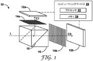
図1は、光センサ12aと、ピクセル化フィルタアレイ14aと、全視野光学選択要素16(「波長選択要素」とも呼ばれる)とを含む例示的な車両支援システム10の概念図である。「全視野」という用語は、光センサ12a又はピクセル化フィルタアレイ14aに入射する全ての光が光学選択要素16を通過するように、光学選択要素16が、光センサ12aとピクセル化フィルタアレイ14aとの全体を光学的にカバーすることを示す。例えば、光学選択要素16からの光は、平行に、角度をなして、収束して、又は発散して出力されるか、他の手法で誘導されるかして、光センサ12a又はピクセル化フィルタアレイ14aを実質的に光学的にカバーし得る。一部の例では、システム10は、光学選択要素16からの光を、光センサ12a若しくはピクセル化フィルタアレイ14aにわたって光学的に拡散するように又は光センサ12a若しくはピクセル化フィルタアレイ14aをカバーするように案内するための1つ以上の光学要素を含んでもよい。ピクセル化フィルタアレイ14aは、光センサ12aに隣接している(例えば、光センサ12aと接触している、又は光センサ12aから間隔をおいて配置され、これと光学的に結合されている)。光学選択要素16は、ピクセル化フィルタアレイ14aに隣接している(例えば、ピクセル化フィルタアレイ14aと接触している、又はピクセル化フィルタアレイ14aから間隔をおいて配置され、これと光学的に結合されている)。
FIG. 1 is a conceptual diagram of an exemplary
光学選択要素16は、光学フィルタ、多層光学フィルム、高精細物品(microreplicated article)、ダイクロイックフィルタ、リターダ即ち波長板、少なくとも1つのビームスプリッタ、又はこれらの組み合わせを含んでもよい。光学選択要素16は、ガラス、1種以上のポリマー、若しくは任意の適切な光学材料、又はこれらの組み合わせを含んでもよい。図1に示す例では、全視野光学選択要素16はビームスプリッタを含む。一部の例では、ビームスプリッタは、偏光ビームスプリッタ、波長ビームスプリッタ、ダイクロイックプリズム、トリクロイックプリズム、又はこれらの組み合わせを含む。ビームスプリッタは2つの三角プリズムを含み、2つの三角プリズムはそれらの底面で(例えば、接着剤によって)接合され、界面18を形成している。到達する光信号を2つ以上のスペクトル成分、例えば、異なる波長又は偏光状態を有する成分に分割するためのダイクロイックコーティング又は層が界面18に提供され得る。光学選択要素16は、波長選択性であっても、偏光選択性であっても、これら両方であってもよい。所定の波長又は偏光状態をフィルタリングするために、例えば、選択的に吸収、透過、又は変化させるために、光学コーティング又はフィルタが、光学選択要素16の1つ以上の面上に又は光学選択要素16の1つ以上の面に隣接して(例えば、接触して)提供されてもよい。一部の例では、光学コーティングは、偏光方向を変化させるために、又は直線偏光を円偏光に変えるために、波長板即ちリターダ、例えば、半波長リターダ又は四分の一波長リターダを含んでもよい。一部の例では、光学コーティングは、空間的に変異する波長選択フィルタを含む。本開示において、「偏光状態」という用語は、直線偏光状態と円偏光状態とを含む。一部の例では、システム10は、光センサ12aに到達する光路を横切る少なくとも1つの偏光フィルタを含む。一部の例では、光学選択要素16は、紫外線(UV)透過性可視光反射性多層フィルムフィルタ、紫外線(UV)反射性可視光透過性多層フィルムフィルタ、エッジフィルタ、透過ノッチフィルタ(transmission notch filter)、反射ノッチフィルタ(reflective notch filter)、又はマルチバンドフィルタのうちの少なくとも1つを含む。
The
図1に示すように、光学選択要素16は、光学選択要素16に入射する光信号Lを2つの光学成分C1とC2とに分割し、光Lの光学成分C1を、ピクセル化フィルタアレイ14aを通して光センサ12aに選択的に誘導する。一部の例では、第2の光学成分C2は破棄される。他の例では、第2の光学成分C2は別の光センサに送信される。例えば、光センサ12aは第1の光センサを含んでもよく、システム10は第2の光センサ12bを含んでもよい。同様に、ピクセルフィルタアレイ14aは、第1のピクセルフィルタアレイを含んでもよく、システム10は、第2のピクセルフィルタアレイ14bを含んでもよい。したがって、光学選択要素16は、第2の光学成分C2を、第2のピクセル化フィルタアレイ14bを通して第2の光センサ12bに選択的に誘導することができる。ピクセル化フィルタアレイ14a、14bは所定の光の成分を、光センサ12a及び光センサ12bの離散的領域、即ちピクセルに入射させることができる。したがって、各ピクセルは、1つ以上の所定の光のチャネル又は成分に対するサブピクセルを含み得る。例えば、ピクセル化フィルタアレイ14a、14bの各ピクセルは、赤色、緑色、青色、又はクリアのサブピクセルのうちの1つ以上を含み得る。ピクセル化フィルタアレイのサブピクセル構成のいくつかの例は、図6A〜図6Eを参照して記述する。
As shown in FIG. 1, the
一部の例では、ピクセル化フィルタアレイ14a、14bはそれぞれ、例えば同じ集積チップ内に作製された光センサ12a及び光センサ12bと統合されてもよい。したがって、ピクセル化フィルタアレイ14a、14bは、光センサ12a及び光センサ12b上に成長させてもよく、そうでなければ光センサ12a及び光センサ12bと直接接触させてもよい。
In some examples, the
第1の光学成分C1と第2の光学成分C2は、少なくとも1つの波長帯域若しくは偏光状態又はこれらの組み合わせにおいて異なってもよく、C2は、典型的には、C1の光学補完(optical complement)である。一部の例では、第1の光学成分C1は、少なくとも第1の紫外波長帯域、可視波長帯域、又は赤外波長帯域(λ1を中心とする)を含み、第2の光学成分C2は、第1の帯域とは異なる少なくとも第2の紫外帯域、可視帯域、又は赤外帯域(λ2を中心とする)を含む。一部の例では、第1の波長帯域は、200nm未満の帯域幅を有し、第2の波長帯域は、第1の波長帯域のスペクトル補完(spectral complement)を含む。一部の例では、第1の波長帯域は、100nm未満又は50nm未満の帯域幅を有する。一部の例では、第1の波長帯域は、少なくとも1つの可視波長帯域を含み、第2の波長帯域は、少なくとも1つの近赤外帯域を含む。一部の例では、第1の波長帯域は、少なくとも1つの可視波長帯域及び少なくとも第1の近赤外帯域を含み、第2の波長帯域は、少なくとも第2の近赤外帯域を含む。一部の例では、第1の波長帯域は、少なくとも1つの可視波長帯域を含み、第2の波長帯域は、少なくとも1つのUV帯域を含む。一部の例では、第1の波長帯域は、少なくとも第1の1つの可視波長帯域を含み、第2の波長帯域は、少なくとも第2の可視波長帯域を含む。一部の例では、第1の光学成分C1は、第1の偏光状態を含み、第2の光学成分C2は、第1の偏光状態とは異なる少なくとも第2の偏光状態を含む。一部の例では、第1の光センサ12aは撮像センサとして機能し、第2の光センサ12bはハイパースペクトルセンサとして機能する。
The first optical component C1 and the second optical component C2 may differ in at least one wavelength band or polarization state or a combination thereof, where C2 is typically the optical complement of C1. be. In some examples, the first optical component C1 comprises at least the first ultraviolet wavelength band, the visible wavelength band, or the infrared wavelength band ( centered on λ 1 ), and the second optical component C2 is It includes at least a second ultraviolet band, a visible band, or an infrared band (centered on λ 2) different from the first band. In some examples, the first wavelength band has a bandwidth of less than 200 nm and the second wavelength band comprises spectral complement of the first wavelength band. In some examples, the first wavelength band has a bandwidth of less than 100 nm or less than 50 nm. In some examples, the first wavelength band comprises at least one visible wavelength band and the second wavelength band comprises at least one near infrared band. In some examples, the first wavelength band includes at least one visible wavelength band and at least the first near-infrared band, and the second wavelength band includes at least the second near-infrared band. In some examples, the first wavelength band comprises at least one visible wavelength band and the second wavelength band comprises at least one UV band. In some examples, the first wavelength band comprises at least one visible wavelength band and the second wavelength band comprises at least a second visible wavelength band. In some examples, the first optical component C1 comprises a first polarization state and the second optical component C2 comprises at least a second polarization state different from the first polarization state. In some examples, the first
一部の例では、光学選択要素16は角度制限光学要素を含む。一部の例では、角度制限光学要素に加えて又はその代わりに、光学選択要素16は角度拡散光学要素を含む。角度制限要素又は角度拡散要素は、屈折要素、回折要素、レンズ、プリズム、高精細表面若しくは物品(microreplicated surface or article)、又はこれらの組み合わせを含んでもよい。一部の例では、角度拡散光学要素を含む光学選択要素16は、分光計として機能することができ、異なる波長を異なる角度で放出することができる。
In some examples, the
システム10は、コンピューティングデバイス20を含んでもよい。光センサ12a、12bは、コンピューティングデバイス20と電子通信してもよい。コンピューティングデバイス20は、プロセッサ22及びメモリ24を含んでもよい。プロセッサ22は、コンピューティングデバイス20内で実行するための機能及び/又は処理命令を実装するように構成され得る。例えば、プロセッサ22は、記憶デバイス、例えば、コンピューティングデバイス20内のメモリ24によって記憶された命令を処理することができる。プロセッサ22の例としては、マイクロプロセッサ、コントローラ、デジタルシグナルプロセッサ(DSP)、特定用途向け集積回路(ASIC)、フィールドプログラマブルゲートアレイ(FPGA)、又は同等の離散型若しくは集積型論理回路のうちのいずれか1つ以上が挙げられ得る。メモリ24は、複数の参照画像を含むルックアップテーブルを含んでもよい。
The
コンピューティングデバイス20は、光センサ12a、12bから少なくとも1つの画像データ信号を受信してもよく、プロセッサ22は、画像データ信号を複数の参照画像と比較するように構成されてもよい。プロセッサ22は、比較に基づいて、出力信号を生成するように構成されてもよい。コンピューティングデバイス20は、車両のコントローラに出力信号を送信し、コントローラに、出力信号に基づいた動作を取らせることができる。この動作は、物理的動作、通信動作、光伝送、又はセンサの制御若しくは作動を含み得る。一部の例では、コンピューティングデバイス20それ自体が車両のコントローラであってもよい。例えば、コンピューティングデバイス20は、ナビゲーションを指示してもよく、車両の動きを制御してもよい。出力信号は、ナビゲーション動作の調整、通信ネットワークを介した応答信号の検索、通信ネットワークを介した車両環境情報の検索、又は通信ネットワークを介した対象車両への通信信号の送信、のうちの1つ以上を行わせるように構成されてもよい。感知及び又は通信は、別の車両と行われてもよいが、(標識などの)インフラの一部と、又は人と行うこともできる。一部の例では、コンピューティングデバイス20は、異なる車両、インフラ構成要素、又は人に搭載され得るトランシーバと通信してもよい。
The
図2は、物体31によって偏向された光を検知するための、図1の車両支援システム10を含む例示的なシステム30の概念図である。物体31は、陸用車両、空用車両、又は海用車両が遭遇する又はその近傍にある任意の物体を含み得る。例えば、物体31としては、道路標識、建設機器又は標識、歩行者の上着又は衣服、再帰反射性標識、広告板、広告、ナビゲーションマーカ、マイル標石、橋、舗装、路面表示等が挙げられ得る。一部の例では、システム30は、物体31に向けて光を送信するように構成された光送信機32を含む。したがって、光センサ12a、12bは、物体31によって反射又は再帰反射された光送信機32からの光を感知するように構成され得る。一部の例では、システム10は、特定の光送信機を含んでもよく、物体31は、周囲光、例えば日光、又は複数光源から物体31に向けられた光を反射し得る。一部の例では、システム30は、図2に示すようなビームスプリッタの代わりに光学フィルタを含む光学選択要素16を含む。
FIG. 2 is a conceptual diagram of an
図2に示すように、一部の例では、システム30は筐体34を含む。筐体34は、光センサ12a、12bとピクセル化フィルタアレイ14a、14bと光学選択要素16とを内包する、剛性ハウジング又は半剛性若しくは軟質筐体を含んでもよい。筐体34は、光学成分を迷光から保護することができ、かつ光センサ12a、12bが不注意による光への曝露から保護されるように、実質的に不透明であってもよい。一部の例では、筐体34は、光学選択要素16に、最終的には光センサ12a、12bに、光を選択的に受け入れるための光学窓36を画定している。光学窓36は、レンズ(例えば、魚眼レンズ)、屈折要素、光学フィルタを含んでもよく、又は実質的に光学的に透明であってもよい。筐体34は、車両、例えば、空用車両、海用車両、又は陸用車両の適切な位置、領域、又は構成要素に固定又は取り付けられてもよい。一部の例では、筐体34は、光学窓36が車両の進行方向に対して所定の向き、例えば、前方方向、後方方向、又は横方向に面するように固定されてもよい。一部の例では、複数の筐体34が、異なる位置にある又は車両の周囲若しくは車両上で異なる方向に向けられた複数のシステム10若しくは30を内包してもよい。システム10又はシステム30は単一の光学選択要素16を含み得るが、他の例では、例示的なシステムは、例えば、図3を参照して記述するような2つ以上の光学選択要素を含んでもよい。
As shown in FIG. 2, in some examples, the
図3は、物体31によって偏向された光を検知するためのカスケード式光学選択要素16a、16bを含む車両支援システムを含む例示的なシステム40の概念図である。システム40は、例示的なシステム30と実質的に同様であるが、図1及び図2を参照して記述した単一の光学選択要素16と実質的に同様の2つの光学選択要素16a及び16bを含む。システム40は、3つの光センサ12a、12b、12cと3つのピクセル化フィルタアレイ14a、14b、14cとを含む。第1の光学選択要素16aは入射光を2つの成分に分割し、第1の成分は、第1のピクセル化フィルタアレイ14aを通して第1の光センサ12aに誘導される。第2の成分は、第2の成分を更なる2つの成分(第3の成分及び第4の成分)に分割する第2の光学選択要素16bに誘導され、第3の成分は、第2のピクセル化フィルタアレイ14bを通して第2の光センサ12bに選択的に誘導され、第4の成分は、第3のピクセル化フィルタアレイ14cを通して第3の光センサ12cに選択的に誘導される。システム40は、一連の光学成分を同様に分割し、各々のセンサに選択的に誘導する3つ以上の光学選択要素と、4つ以上の光センサ及びピクセル化フィルタアレイとを含んでもよい。異なる成分は、少なくとも1つの波長帯域又は偏光状態が異なり得る。
FIG. 3 is a conceptual diagram of an
ビームスプリッタの代わりに又はそれに加えて、システム10、30、又は40は、他の光学選択要素、例えば、図4及び図5を参照して記述するものを含んでもよい。
Instead of or in addition to the beam splitter, the
図4は、クロスタイプダイクロイックスプリッタを含む例示的な光学選択要素16cの概念図である。クロスタイプダイクロイックスプリッタ(例えば、WTS Photonics Technology Co.,Ltd(Fuzhou,China)から入手可能な「Xキューブ」又は「RGBプリズム」としても知られる)は、ガラス又は別の適切な光学媒体に埋め込まれた2つのダイクロイック界面18b及び18cによって画定され得る。一部の例では、界面18bは赤色及び緑色のフィルタを画定することができ、界面18cは、界面18bを横断するシアン色のフィルタを画定することができる。図4に見られるように、光学選択要素16cは、入射光Lの3つの成分C1、C2、及びC3を3つの別個の方向に沿って実質的に誘導することができる。一部の例では、3つの光センサそれぞれは、3つの成分を別々に検知することができる。C1、C2、及びC3は、UV波長、可視波長、又はIR波長と偏光状態との任意の適切な所定の組み合わせに対応し得る。一部の例では、C1、C2、及びC3は、赤色チャネル、緑色チャネル、及び青色チャネルに対応し得る。
FIG. 4 is a conceptual diagram of an exemplary
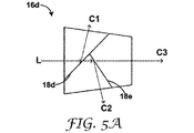
図5Aは、トリクロイックプリズムを含む例示的な光学選択要素16dの概念図である。トリクロイックプリズムは、ガラス又は任意の適切な光学媒体によって画定することができ、所定の角度の2つのダイクロイック界面18d及び18eを含むことができる。ダイクロイック界面18d及び18eは、ダイクロイックフィルタとして機能し、入射光Lの異なる成分、例えば、C1、C2、及びC3を3つの別個の方向に沿って誘導することができる。一部の例では、3つの光センサそれぞれは、3つの成分を別々に検知することができる。C1、C2、及びC3は、UV波長、可視波長、又はIR波長(例えば、所定の波長λ1、λ2、及びλ3を中心とする帯域)と偏光状態との任意の適切な所定の組み合わせに対応し得る。一部の例では、C1、C2、及びC3は、赤色チャネル、緑色チャネル、及び青色チャネルに対応し得る。
FIG. 5A is a conceptual diagram of an exemplary
図5Bは、トリクロイックプリズムを含む例示的な光学選択要素16eの概念図である。トリクロイックプリズムは、ガラス又は任意の適切な光学媒体によって画定することができ、プリズム要素又は屈折要素間にダイクロイック界面を含むことができる。ダイクロイック界面は、ダイクロイックフィルタとして機能し、入射光Lの異なる成分、例えば、C1、C2、及びC3を3つの別個の方向に沿って誘導することができる。一部の例では、3つの光センサそれぞれは、3つの成分を別々に検知することができる。C1、C2、及びC3は、UV波長、可視波長、又はIR波長(例えば、所定の波長λ1、λ2、及びλ3を中心とする帯域)と偏光状態との任意の適切な所定の組み合わせに対応し得る。一部の例では、C1、C2、及びC3は、赤色チャネル、緑色チャネル、及び青色チャネルに対応し得る。 FIG. 5B is a conceptual diagram of an exemplary optical selection element 16e including a trichromatic prism. The trichromic prism can be defined by glass or any suitable optical medium and can include a dichroic interface between the prism element or the refracting element. The dichroic interface acts as a dichroic filter and can guide different components of the incident light L, such as C1, C2, and C3, along three distinct directions. In some examples, each of the three optical sensors can detect the three components separately. C1, C2, and C3 are any suitable predetermined combination of UV wavelength, visible wavelength, or IR wavelength (eg, a band centered on the predetermined wavelengths λ 1 , λ 2 , and λ 3 ) and the polarization state. Can correspond to. In some examples, C1, C2, and C3 may correspond to red, green, and blue channels.
ピクセル化フィルタアレイ14a、14bの代わりに又はそれに加えて、システム10、30、又は40は、他のピクセル化フィルタアレイ、例えば、図6A〜図6Eを参照して記述するものを含んでもよい。
Instead of or in addition to the
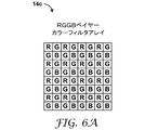
図6Aは、ベイヤーカラーフィルタアレイの概念図である。ベイヤーカラーフィルタアレイは、各ブロック内に赤色のピクセルと青色のピクセルと2つの緑色のピクセルと(RGGB)を含む。図6Aには赤色のピクセル、緑色のピクセル、及び青色のピクセルの特定の相対配置が示されているが、他の幾何学的配置も使用してよい。ベイヤーカラーフィルタアレイは、赤色波長領域、緑色波長領域、及び青色波長領域の光の強度に関する情報を、これらの波長を隣接するイメージセンサの離散的領域に送ることによりもたらす。その後、イメージセンサによって捕捉された生画像データは、各ピクセル又はブロックで表される全3原色(赤、緑、青)の強度を持つデモザイク処理アルゴリズムによってフルカラー画像に変換される。ベイヤーカラーフィルタアレイは、25%のRピクセル、25%のBピクセル、及び50%のGピクセルを有する。 FIG. 6A is a conceptual diagram of a Bayer color filter array. The Bayer color filter array contains a red pixel, a blue pixel, and two green pixels (RGGB) within each block. Although FIG. 6A shows specific relative arrangements of red, green, and blue pixels, other geometric arrangements may be used. The Bayer color filter array provides information about the intensity of light in the red, green, and blue wavelength regions by sending these wavelengths to the discrete regions of adjacent image sensors. The raw image data captured by the image sensor is then converted into a full-color image by a demosaic processing algorithm with the intensities of all three primary colors (red, green, blue) represented by each pixel or block. The Bayer color filter array has 25% R pixels, 25% B pixels, and 50% G pixels.
図6Bは、赤/クリア/クリア/クリア(RCCC)カラーフィルタアレイの概念図である。車両支援システム又は先進運転支援システム(ADAS)においては、輸送中の支援のために、複数のカメラが車両周辺のシーンを撮影してもよい。典型的なマシンビジョンアルゴリズムは、光の強度のみを使用又は解析することができる。しかし、ADASにおいては、色情報を提供するために、特別なカラーフィルタアレイが作成され得る。有用な色情報チャネルの1つは赤色チャネルにあり、赤色チャネルは、信号機、自動車の尾灯等のような、画像の関心領域を特定するのに役立つ。車両支援用途においては、赤/クリア(RCCC)カラーフィルタアレイが使用されてもよい。ベイヤーセンサとは異なり、RCCCセンサは、2x2ピクセルパターンの青色と2つの緑色のフィルタの代わりにクリアフィルタを使用し、光の強度情報を与えて色情報は与えないクリアピクセルを75%有する。ピクセルの25%は赤色の色情報を有する。赤色フィルタは同じままである。「クリアフィルタ」は、モノクロセンサと同じ概念である。この形式の利点は、光に対する感度をより高くすることができるので、暗い条件でより良好に機能し得ることである。したがって、一部の例では、本開示によるピクセル化フィルタアレイは、少なくとも1つのクリアピクセル、例えば、複数のクリアピクセルを含んでもよい。 FIG. 6B is a conceptual diagram of a red / clear / clear / clear (RCCC) color filter array. In a vehicle assistance system or an advanced driver assistance system (ADAS), a plurality of cameras may capture a scene around the vehicle for assistance during transportation. Typical machine vision algorithms can use or analyze only the intensity of light. However, in ADAS, special color filter arrays may be created to provide color information. One of the useful color information channels is in the red channel, which helps identify areas of interest in the image, such as traffic lights, taillights of automobiles, and so on. For vehicle support applications, red / clear (RCCC) color filter arrays may be used. Unlike the Bayer sensor, the RCCC sensor uses a clear filter instead of the blue and two green filters of the 2x2 pixel pattern and has 75% of clear pixels that give light intensity information but not color information. Twenty-five percent of the pixels have red color information. The red filter remains the same. "Clear filter" is the same concept as a monochrome sensor. The advantage of this format is that it can function better in dark conditions, as it can be more sensitive to light. Thus, in some examples, the pixelated filter array according to the present disclosure may include at least one clear pixel, eg, a plurality of clear pixels.
図6Cは、モノクロフィルタアレイの概念図である。モノクロアレイは、光の強度情報を与え、色情報は与えない「クリア」ピクセルを100%有する。これは、色情報が必要ない(例えば、運転者の監視)モノクロ観察(monochrome viewing)又は解析用途のいずれかで許容できる。この形式の利点は、光に対する感度がより高いので、暗い条件でより良好に機能し得ることである。 FIG. 6C is a conceptual diagram of a monochrome filter array. Monochrome arrays have 100% "clear" pixels that provide light intensity information and no color information. This is acceptable for either monochrome viewing or analytical applications where no color information is required (eg, driver monitoring). The advantage of this format is that it is more sensitive to light and can work better in dark conditions.
図6Dは、赤/クリア/クリア/青(RCCB)カラーフィルタアレイの概念図である。RCCBは、ピクセルの半分が緑ではなくクリアであることを除いて、ベイヤー(RGGB)と類似している。この形式の利点は、クリアピクセルがより低い光の感度をもたらすので、ノイズの低下につながることである。この形式は、視覚的用途及び解析用途に同じカメラを使用できる可能性がある。 FIG. 6D is a conceptual diagram of a red / clear / clear / blue (RCCB) color filter array. The RCCB is similar to the Bayer (RGGB), except that half of the pixels are clear rather than green. The advantage of this format is that clear pixels provide lower light sensitivity, which leads to lower noise. This format may allow the same camera to be used for visual and analytical applications.
図6Eは、赤/クリア/クリア/青(RCCB)カラーフィルタアレイの概念図である。RGCBは、緑色ピクセルの半分が緑ではなくクリアであることを除いて、ベイヤー(RGGB)と類似している。この形式の利点は、クリアピクセルがより低い光の感度をもたらすので、ノイズの低下につながることである。この形式は、視覚的用途及び解析用途に同じカメラを使用できる可能性がある。 FIG. 6E is a conceptual diagram of a red / clear / clear / blue (RCCB) color filter array. The RGCB is similar to the Bayer (RGGB), except that half of the green pixels are clear rather than green. The advantage of this format is that clear pixels provide lower light sensitivity, which leads to lower noise. This format may allow the same camera to be used for visual and analytical applications.
クリアピクセルは、可視波長、赤外波長、若しくは紫外波長、又はこれらの組み合わせのうちの1つ以上において透過性であり得る。一部の例では、クリアピクセルは、実質的に可視波長のみに透過性である。一部の例では、クリアピクセルは、実質的に赤外波長のみに透過性である。一部の例では、クリアピクセルは、実質的に紫外波長のみに透過性である。一部の例では、クリアピクセルは、実質的に可視波長及び赤外波長のみに透過性である。 Clear pixels can be transparent at visible wavelengths, infrared wavelengths, or ultraviolet wavelengths, or one or more of these combinations. In some examples, clear pixels are substantially transparent only to visible wavelengths. In some examples, clear pixels are substantially transparent only to infrared wavelengths. In some examples, clear pixels are substantially transparent only to UV wavelengths. In some examples, clear pixels are substantially transparent only to visible and infrared wavelengths.
異なるカラーフィルタアレイを利用できるが、光学選択要素を含まないシステムは問題を呈する可能性がある。例えば、光学選択要素がないと、車両支援システム又はADASは、IR及びUVにおけるスペクトル分解能の制限、偏光情報の欠如、偏光子が使用される場合の信号損失、フィルタリングによる信号損失、及びチャネル間の乏しいコントラストを呈する可能性がある。 Different color filter arrays are available, but systems that do not include optical selection elements can present problems. For example, in the absence of optical selection elements, vehicle assistance systems or ADAS will limit spectral resolution in IR and UV, lack polarization information, signal loss when a spectrometer is used, signal loss due to filtering, and between channels. May exhibit poor contrast.
本開示による例示的なシステムでは、1つ以上の光学選択要素が、例えば、チャネルを分離してより良好なコントラストを提供すること、干渉する波長を排除又は減衰させること、IR及びUVにおけるスペクトル分解能を向上させること、並びに偏光情報を得ることによって、これらの問題の1つ以上に対処することができる。例示的な波長選択要素によって光を異なる成分に分割するいくつかの例を、図7A〜図7Hを参照して記述する。 In an exemplary system according to the present disclosure, one or more optical selection elements, for example, separating channels to provide better contrast, eliminating or attenuating interfering wavelengths, spectral resolution in IR and UV. One or more of these problems can be addressed by improving and obtaining polarization information. Some examples of dividing light into different components by exemplary wavelength selection elements are described with reference to FIGS. 7A-7H.
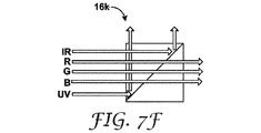
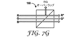
図7Aは、赤外波長帯域を反射し、可視光を透過するように構成された全視野光学選択要素16fの概念図である。図7Bは、第1の赤外波長帯域を反射し、第2の赤外波長帯域及び可視光を透過するように構成された全視野光学選択要素16fの概念図である。図7Cは、第1及び第2の赤外波長帯域を反射し、第3の赤外波長帯域及び可視光を透過するように構成された全視野光学選択要素16hの概念図である。図7Dは、赤外波長帯域を反射し、可視光及び紫外波長帯域を透過するように構成された全視野光学選択要素16iの概念図である。図7Eは、紫外波長帯域を反射し、可視光及び赤外波長帯域を透過するように構成された全視野光学選択要素16jの概念図である。図7Fは、赤外波長帯域及び紫外波長帯域を反射し、可視光を透過するように構成された全視野光学選択要素16kの概念図である。図7Gは、第1の赤色及び緑色波長帯域を反射し、第2及び緑色波長帯域並びに青色波長帯域を透過するように構成された全視野光学選択要素16lの概念図である。図7Hは、s偏光された赤色波長帯域を反射し、p偏光された赤色波長帯域を透過し、緑色及び青色波長帯域を透過するように構成された全視野光学選択要素16mの概念図である。狭帯域のs偏光反射体を使用することによって、信号損失を低減した又は最小限にした偏光の検知が可能になる。2つの、s偏光画像とp偏光画像との間の画像解析を、シーンの偏光分析のために使用することができる。舗装が濡れているかどうかを判断するなどの路面状態の検知が1つの例である。別の例は、舗装表示のスペクトルを解析できるように表面のグレアを排除することである。
FIG. 7A is a conceptual diagram of a full-field optical selection element 16f configured to reflect an infrared wavelength band and transmit visible light. FIG. 7B is a conceptual diagram of the full-field optical selection element 16f configured to reflect the first infrared wavelength band and transmit the second infrared wavelength band and visible light. FIG. 7C is a conceptual diagram of the full-field
図7A〜図7Hの例では、フィルタは立方体(対角線上の界面)内にあるが、他の例では、立方体の対角線上のフィルタに加えて又はその代わりに、フィルタは立方体の表面上に配置されてもよい。一部の例では、対角線上のフィルムは、波長選択性の立方体表面フィルタと組み合わせて使用されるハーフミラーを含んでもよい。フィルタは、狭帯域反射フィルタ及び狭帯域透過フィルタを含んでもよい。 In the example of FIGS. 7A-7H, the filter is in the cube (diagonal interface), but in other examples, in addition to or instead of the filter on the diagonal of the cube, the filter is placed on the surface of the cube. May be done. In some examples, the diagonal film may include a half mirror used in combination with a wavelength selective cubic surface filter. The filter may include a narrowband reflection filter and a narrowband transmission filter.
図8は、レンズ42を含む例示的な光学選択要素16mの概念図である。レンズ42は、光学選択要素16n(例えば、多層光学フィルム)内のフィルタ上に様々な入射角を生じさせ、これにより、上向きの波長シフトをもたらす。波長シフトは、上面に隣接するイメージセンサによって検知され得る。第2のレンズ44は、光学選択要素16mの右面に隣接する第2のイメージセンサ上に光を収束させることができる。
FIG. 8 is a conceptual diagram of an exemplary
図9は、湾曲した反射性界面46を含む例示的な視野光学選択要素16oの概念図である。一部の例では、湾曲した反射性界面46は、湾曲多層光学フィルム(MOF)を含んでもよい。この曲率により、後にピクセル位置にマッピングされる様々な入射角を生じさせる。各ピクセル位置は、異なる反射スペクトルの効果を感知する。1つの特定の曲線が図9に示されているが、界面46は、直線線分、円弧、楕円弧、放物線弧若しくは双曲線弧、面分、球面、楕円面、放物面、双曲面、自由面若しくは弧、又はこれらの組み合わせを含む、任意の適切な幾何学的曲線、複合曲線、表面、又は複合表面に沿って配置されてもよい。一部の例では、図9に示すように、界面46は、IR反射性可視光透過性フィルムを含む。IRでは角波長シフトが発生し、上面に拡散する光線を提供する一方で、可視光は右面を通過する。分離された成分を捕捉するために、それぞれの面に隣接するイメージャが配置され得る。
FIG. 9 is a conceptual diagram of an exemplary visual field optical selection element 16o including a curved
図10は、傾斜した反射体48を含む例示的な光学選択要素16pの概念図である。傾斜した反射体48は、2つの入射角を生じさせるために使用され得る。一部の例では、傾斜した反射体48は、湾曲した界面46と同様に、湾曲していてもよい。傾斜又は湾曲した反射体48は、図10に示すように、光を2つの成分に分離することができる。光学選択要素16oは、対角線上の界面にフィルタ18fを含んでもよい。
FIG. 10 is a conceptual diagram of an exemplary
図11Aは、自動運転支援システム(ADAS)を含む車両50の概念図である。図11Bは、図11Aの車両50の概念的な部分正面図である。ADASは、図1を参照して記述したシステム10、又はシステム30若しくはシステム40を含んでもよい。例えば、システム10、30、又は40は、車両50の本体又はフレーム52に固定された筐体(例えば、筐体34、又は類似の筐体)内に取り付けられてもよい又は内包されてもよい。システム10は、物体56によって偏向された光54を検知することができる。一部の例では、車両50は、物体56によってシステム10へと偏向される(例えば、反射又は再帰反射される)光60を物体56に向けて送る光源58を含んでもよい。光源58は、ヘッドライト即ち車両灯62、又はヘッドライト即ち車両灯62とは別個の専用の光源64(又はこれらの組み合わせ)を含んでもよい。図11Aには自動車が示されているが、車両50は、任意の陸用車両、海用車両、又は空用車両を含んでもよい。
FIG. 11A is a conceptual diagram of a
図12は、車両支援システムによって光学信号を感知するための例示的な手法のフローチャートである。図12の例示的な手法について、図1のシステム10及び図2のシステム30を参照しながら記述する。しかしながら、例示的な手法は、本開示による任意の適切なシステムを使用して実施することができる。一部の例では、例示的手法は、車両支援システム10の全視野光学選択要素16によって、物体31から光信号Lを受信すること(70)を含む。例示的手法は、光学選択要素16によって、光信号Lの光学成分C1を、ピクセル化フィルタアレイ14aを通して光センサ12aに選択的に誘導すること(72)を含む。
FIG. 12 is a flowchart of an exemplary method for sensing an optical signal by a vehicle assist system. An exemplary method of FIG. 12 will be described with reference to
例示的手法は、コンピューティングデバイス20によって、光信号Lに応じたイメージセンサ12aからの画像データ信号を受信すること(74)を含む。一部の例では、画像データ信号は、ある瞬間に捕捉された単一の画像に相当し得る。他の例では、画像データ信号は、リアルタイムで、ほぼリアルタイムで、又は断続的な時に捕捉された一連の画像を含んでもよい。一部の例では、光源32は、所定の周波数又は所定の時間パターンを有する光信号を物体31に照射することができ、物体31は、応答周波数又は応答時間パターンを有する応答信号を偏向することができる。一部のこのような例では、受信する光信号L(74)は、物体31に送信される光信号と同期されてもよい、又はこれと非同期であってもよい。
An exemplary method comprises receiving an image data signal from the
例示的手法は、コンピューティングデバイス20によって、画像データ信号をルックアップテーブル内の複数の参照画像と比較すること(76)を含む。比較は、1つの瞬間に捕捉された単一の画像に対してであってもよい、又はリアルタイムで、ほぼリアルタイムで、若しくは断続的な時に捕捉された一連の画像に対する一連の比較を含んでもよい。一部の例では、ルックアップテーブルは、機械学習モジュール、例えば、深層学習モデル、若しくは畳み込みニューラルネットワーク、若しくはパターン認識モジュールによって実装されてもよい、又はこれと置換されてもよい。したがって、一部の例では、ルックアップテーブルのエントリは、画像に関連付けられた機械学習モジュール又はパターン認識モジュールの出力に対応してもよい。一部の例では、光信号Lは、光源32によって生成されたスペクトルS(λ)を有する光信号に応答して、物体31により生成され得る。イメージセンサ12a及びピクセル化フィルタアレイ14aは、第1の波長透過関数T1(λ)を有し得る。光学選択要素16は第2の透過関数T2(λ)を有し得る。物体31は、反射スペクトルR(λ)を有し得る。このような例では、イメージセンサ12aによって受信される信号Lの成分は、S(λ)*T1(λ)*T2(λ)*R(λ)に相当し得るものであり、コンピューティングデバイス20は、S(λ)*T1(λ)*T2(λ)*R(λ)をルックアップテーブルの要素と比較することができる。
An exemplary technique comprises comparing an image data signal with a plurality of reference images in a look-up table by a computing device 20 (76). The comparison may be for a single image captured at one moment, or may include a series of comparisons for a series of images captured in real time, near real time, or intermittently. .. In some examples, the lookup table may be implemented or replaced by a machine learning module, such as a deep learning model, or a convolutional neural network, or a pattern recognition module. Therefore, in some examples, the lookup table entry may correspond to the output of the machine learning module or pattern recognition module associated with the image. In some examples, the optical signal L may be generated by the
例示的手法は、コンピューティングデバイス20によって、比較に応じて、出力信号を生成すること(78)を含む。一部の例では、出力信号は、ナビゲーション動作の調整、通信ネットワークを介した応答信号の検索、通信ネットワークを介した車両環境情報の検索、又は通信ネットワークを介した対象車両への通信信号の送信、のうちの1つ以上を行わせるように構成されている。
An exemplary approach comprises generating an output signal (78), depending on the comparison, by the
本開示による例示的なシステム又は手法は、車両の代わりに、非車両用システム、例えば、ハンドヘルドデバイス、ウェアラブルデバイス、コンピューティングデバイス等に実装されてもよい。 The exemplary system or method according to the present disclosure may be implemented in a non-vehicle system, such as a handheld device, a wearable device, a computing device, etc., instead of the vehicle.
本開示で説明される技術は、ハードウェア、ソフトウェア、ファームウェア、又はそれらの任意の組み合わせに少なくとも部分的に実装してもよい。例えば、説明された技法のさまざまな態様は、1つ以上のマイクロプロセッサ、デジタル信号プロセッサ(DSP)、特定用途向け集積回路(ASIC)、フィールドプログラマブルゲートアレイ(FPGA)、又は他の任意の等価集積回路又は個別論理回路、並びにかかる構成要素の任意の組み合わせを含む1つ以上のプロセッサに実装することができる。用語「プロセッサ」又は「処理回路」は、一般的に、前述の論理回路の単独又は他の論理回路との組み合わせ、あるいは他の等価回路、のいずれかを指してもよい。ハードウェアを含む制御ユニットもまた、本開示の1つ以上の技法を実行することができる。 The techniques described in the present disclosure may be at least partially implemented in hardware, software, firmware, or any combination thereof. For example, various aspects of the techniques described may be one or more microprocessors, digital signal processors (DSPs), application specific integrated circuits (ASICs), field programmable gate arrays (FPGAs), or any other equivalent integration. It can be implemented in one or more processors, including circuits or individual logic circuits, as well as any combination of such components. The term "processor" or "processing circuit" may generally refer to either the aforementioned logic circuit alone or in combination with other logic circuits, or other equivalent circuits. Control units, including hardware, can also perform one or more techniques of the present disclosure.
かかるハードウェア、ソフトウェア、及びファームウェアは、本開示で説明されるさまざまな技法をサポートするために、同じデバイス内又は別個のデバイス内に実装してもよい。更に、記載されたユニット、モジュール又は構成要素のいずれかは、個別であるが相互運用可能な論理デバイスとして一緒に又は別々に実現することができる。モジュール又はユニットとしての異なる特徴の描写は、異なる機能的な態様を強調するように意図されており、必ずしもかかるモジュール又はユニットを別個のハードウェア、ファームウェア、又はソフトウェアの構成要素によって実現しなければならないことを意味するものではない。むしろ、1つ以上のモジュール又はユニットに関連付けられた機能は、別個のハードウェア、ファームウェア、又はソフトウェアの構成要素によって実行してもよく、あるいは、共通の又は別個のハードウェア、ファームウェア、又はソフトウェアの構成要素に統合してもよい。 Such hardware, software, and firmware may be implemented within the same device or within separate devices to support the various techniques described in this disclosure. Moreover, any of the described units, modules or components can be implemented together or separately as separate but interoperable logical devices. The depiction of different features as a module or unit is intended to emphasize different functional aspects, and such module or unit must necessarily be realized by separate hardware, firmware, or software components. It doesn't mean that. Rather, the functions associated with one or more modules or units may be performed by separate hardware, firmware, or software components, or of common or separate hardware, firmware, or software. It may be integrated into a component.
本開示で説明された技法はまた、命令を含むコンピュータシステム可読記憶媒体などのコンピュータシステム可読媒体において具現化又はコード化してもよい。コンピュータシステム可読記憶媒体を含むコンピュータシステム可読媒体に埋め込まれるか又はコード化された命令によって、コンピュータシステム可読媒体中に含まれるか又はコード化された命令が1つ以上のプロセッサによって実行されるときのように、1つ以上のプログラム可能なプロセッサ又は他のプロセッサにより本明細書に記載された技法の1つ以上を実施することが可能である。コンピュータシステム可読記憶媒体としては、ランダムアクセスメモリ(RAM)、読み出し専用メモリ(ROM)、プログラム可能読み出し専用メモリ(PROM)、消去可能プログラム可能読み出し専用メモリ(EPROM)、電子消去可能プログラマブル読み出し専用メモリ(EEPROM)、フラッシュメモリ、ハードディスク、コンパクトディスクROM(CD−ROM)、フロッピーディスク、カセット、磁気媒体、光媒体、又は他のコンピュータシステム可読媒体を挙げることができる。一部の例では、製造物品は、1つ以上のコンピュータシステム可読記憶媒体を含んでもよい。 The techniques described in the present disclosure may also be embodied or encoded in a computer system readable medium, such as a computer system readable storage medium containing instructions. When an instruction contained in or coded in a computer system readable medium is executed by one or more processors by an instruction embedded in or coded in a computer system readable medium, including a computer system readable storage medium. As such, it is possible to perform one or more of the techniques described herein by one or more programmable processors or other processors. Computer system readable storage media include random access memory (RAM), read-only memory (ROM), programmable read-only memory (ROM), erasable programmable read-only memory (EPROM), and electronically erasable programmable read-only memory (ROM). EEPROM), flash memory, hard disk, compact disk ROM (CD-ROM), floppy disk, cassette, magnetic medium, optical medium, or other computer system readable medium. In some examples, the manufactured article may include one or more computer system readable storage media.
実施例1
コード化パターンの仮想実施例について記述する。図13は、車両支援システムによって読み取り可能なコード化パターンの概念図である。パターンは、二次元(2D)QRバーコードを共に画定する2つの構成物を含む。第1の構成物は、第1の波長λ1に遷移端を有する第1の色素を含む。第2の構成物は、λ1よりも高い第2の波長λ2に遷移端を有する第2の色素を含む。狭い波長範囲でパターンが照明又は観察されると、λ1及びλ2においてパターンを撮像するイメージセンサから画像データを受信するコンピューティングデバイスは、合成コードが実際には、図13に示されるような2つの別個のコードで出来ていることを検知することができる。コンピューティングデバイスは、2つの別個のコードを組み合わせて、組み合わされたパターンを生成し、組み合わされたパターンから情報を検知することができる。
Example 1
A virtual example of the coding pattern is described. FIG. 13 is a conceptual diagram of a coding pattern that can be read by the vehicle support system. The pattern contains two constructs that together define a two-dimensional (2D) QR barcode. The first construct comprises a first dye having a transition end at the first wavelength λ 1. The second construct comprises a second dye having a transition end at a second wavelength λ 2 higher than λ 1. When the pattern is illuminated or observed in a narrow wavelength range, a computing device that receives image data from an image sensor that captures the pattern in λ 1 and λ 2 has a synthetic code as shown in FIG. It can detect that it is made up of two separate codes. A computing device can combine two separate codes to generate a combined pattern and detect information from the combined pattern.
実施例2
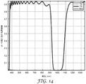
光学選択要素の仮想実施例について記述する。1000nmを中心とする一次反射を有し、二次反射が調整される狭帯域遮断多層光学フィルム(MOF)が使用される。この帯域幅は、50nm〜200nmで調整される。図14は、例示的な狭帯域遮断多層光学フィルム(MOF)のスペクトルを示すチャートである。図15Aは、図14のMOFの、空気中での波長と極角と反射率との間の関係を示すチャートである。図15Bは、図14のMOFの、空気中での波長と極角と透過率との間の関係を示すチャートである。受光角は、±40°である。
Example 2
A virtual embodiment of the optical selection element will be described. A narrowband cutoff multilayer optical film (MOF) having a primary reflection centered at 1000 nm and having a regulated secondary reflection is used. This bandwidth is adjusted from 50 nm to 200 nm. FIG. 14 is a chart showing the spectrum of an exemplary narrowband cutoff multilayer optical film (MOF). FIG. 15A is a chart showing the relationship between the wavelength, the polar angle, and the reflectance in the air of the MOF of FIG. FIG. 15B is a chart showing the relationship between the wavelength, the polar angle, and the transmittance of the MOF of FIG. 14 in the air. The light receiving angle is ± 40 °.
図16Aは、図14のMOFの、ガラス内(ガラス製ビームスプリッタ立方体)での波長と極角と反射率との間の関係を示すチャートである。図16Bは、図14のMOFの、ガラス内での波長と極角と透過率との間の関係を示すチャートである。図16Cは、図14のMOFの、ガラス内での波長と極角とp偏光透過率との間の関係を示すチャートである。図16Dは、図14のMOFの、ガラス内での波長と極角とs偏光透過率との間の関係を示すチャートである。光は、立方体内に45°±15°の円錐形で入射する。これは、高い角度シフトを示し、したがって、フィルム上の光の入射角を制限するためのコリメーション光学系の必要性を示す。 FIG. 16A is a chart showing the relationship between the wavelength, the pole angle, and the reflectance in the glass (glass beam splitter cube) of the MOF of FIG. FIG. 16B is a chart showing the relationship between the wavelength, the polar angle, and the transmittance of the MOF of FIG. 14 in the glass. FIG. 16C is a chart showing the relationship between the wavelength, the polar angle, and the p-polarized light transmittance of the MOF of FIG. 14 in the glass. FIG. 16D is a chart showing the relationship between the wavelength, the polar angle, and the s polarization transmittance of the MOF of FIG. 14 in the glass. Light enters the cube in the shape of a 45 ° ± 15 ° cone. This indicates a high angle shift and thus indicates the need for collimation optics to limit the angle of incidence of light on the film.
実施例3
デュアルバンド光学選択要素の仮想実施例について記述する。この要素は、それぞれ800nm及び1000nmの単一帯域を有する2つの多層光学フィルム(MOF)をラミネートする(laminating)ことによって作製されるフィルタを含む。350nm〜1000nm又はこれ以上のマルチバンドを用いることができる。図17は、例示的なデュアルバンド遮断多層光学フィルム(MOF)のスペクトルを示すチャートである。図18Aは、図17のMOFの、空気中での波長と極角と反射率との間の関係を示すチャートである。図18Bは、図17のMOFの、空気中での波長と極角と透過率との間の関係を示すチャートである。2つの帯域は個々に調整可能である。
Example 3
A virtual example of a dual band optical selection element will be described. This element includes a filter made by laminating two multilayer optical films (MOFs) with single bands of 800 nm and 1000 nm, respectively. Multi-bands of 350 nm to 1000 nm or more can be used. FIG. 17 is a chart showing the spectrum of an exemplary dual band cutoff multilayer optical film (MOF). FIG. 18A is a chart showing the relationship between the wavelength, the polar angle, and the reflectance in the air of the MOF of FIG. FIG. 18B is a chart showing the relationship between the wavelength, the polar angle, and the transmittance of the MOF of FIG. 17 in the air. The two bands are individually adjustable.
本発明のさまざまな実施例について説明した。これら及び他の実施例は、以下の特許請求の範囲内である。 Various embodiments of the present invention have been described. These and other examples are within the scope of the following claims.
Claims (34)
前記光センサに隣接するピクセル化フィルタアレイと、
前記ピクセル化フィルタアレイに隣接する全視野光学選択要素であって、前記光学選択要素は、前記光学選択要素に入射する光の光学成分を、前記ピクセル化フィルタアレイを通して前記光センサに選択的に誘導するように構成されている、全視野光学選択要素と、
を備える、車両支援システム。 Optical sensor and
A pixelated filter array adjacent to the optical sensor and
A full-field optical selection element adjacent to the pixelated filter array, wherein the optical selection element selectively guides optical components of light incident on the optical selection element to the optical sensor through the pixelated filter array. With a full-field optical selection element, which is configured to
A vehicle support system equipped with.
複数の参照画像を備えるルックアップテーブルを備えるメモリと、
前記画像データ信号を前記複数の参照画像と比較し、前記比較に応じて出力信号を生成するように構成されたプロセッサと、
を備える、請求項1〜27のいずれか一項に記載のシステム。 Further comprising a computing device configured to receive an image data signal from an image sensor, said computing device.
Memory with a look-up table with multiple reference images,
A processor configured to compare the image data signal with the plurality of reference images and generate an output signal according to the comparison.
The system according to any one of claims 1 to 27.
前記全視野光学選択要素によって、前記光信号の光学成分を、ピクセル化フィルタアレイを通して光センサに選択的に誘導することと、
を含む、方法。 Receiving an optical signal from an object by the full-field optical selection element of the vehicle assistance system,
The full-field optical selection element selectively guides the optical component of the optical signal to the optical sensor through a pixelated filter array.
Including, how.
前記コンピューティングデバイスによって、前記画像データ信号をルックアップテーブル内の複数の参照画像と比較することと、
前記コンピューティングデバイスによって、前記比較に応じて、出力信号を生成することと、
を更に含む、請求項32に記載の方法。 Receiving an image data signal from the image sensor in response to the optical signal by the computing device.
Comparing the image data signal with a plurality of reference images in a look-up table by the computing device.
Producing an output signal by the computing device in response to the comparison.
32. The method of claim 32.
Applications Claiming Priority (3)
| Application Number | Priority Date | Filing Date | Title |
|---|---|---|---|
| US201862712791P | 2018-07-31 | 2018-07-31 | |
| US62/712,791 | 2018-07-31 | ||
| PCT/IB2019/056445 WO2020026115A1 (en) | 2018-07-31 | 2019-07-29 | Vehicle assistance systems |
Publications (2)
| Publication Number | Publication Date |
|---|---|
| JP2021533633A true JP2021533633A (en) | 2021-12-02 |
| JPWO2020026115A5 JPWO2020026115A5 (en) | 2022-08-05 |
Family
ID=69232381
Family Applications (1)
| Application Number | Title | Priority Date | Filing Date |
|---|---|---|---|
| JP2021505414A Withdrawn JP2021533633A (en) | 2018-07-31 | 2019-07-29 | Vehicle support system |
Country Status (5)
| Country | Link |
|---|---|
| US (1) | US20210168269A1 (en) |
| EP (1) | EP3831048A4 (en) |
| JP (1) | JP2021533633A (en) |
| CN (1) | CN112840633A (en) |
| WO (1) | WO2020026115A1 (en) |
Families Citing this family (5)
| Publication number | Priority date | Publication date | Assignee | Title |
|---|---|---|---|---|
| US11462105B2 (en) * | 2020-05-26 | 2022-10-04 | Accenture Global Solutions Limited | Sensor and filter configuration to detect specific wavelengths of light |
| CA3204541A1 (en) * | 2021-02-01 | 2022-08-04 | Veronica Marin | Machine-learned explainable object detection system and method |
| CN113630571B (en) * | 2021-07-13 | 2024-04-02 | 北京汽车股份有限公司 | High-altitude parabolic monitoring method and system for vehicle |
| DE102021120588A1 (en) | 2021-08-09 | 2023-02-09 | Schölly Fiberoptic GmbH | Image recording device, image recording method, corresponding method for setting up and endoscope |
| US20230169689A1 (en) * | 2021-11-30 | 2023-06-01 | Texas Instruments Incorporated | Suppression of clipping artifacts from color conversion |
Family Cites Families (17)
| Publication number | Priority date | Publication date | Assignee | Title |
|---|---|---|---|---|
| US6118383A (en) * | 1993-05-07 | 2000-09-12 | Hegyi; Dennis J. | Multi-function light sensor for vehicle |
| JP2005229317A (en) * | 2004-02-12 | 2005-08-25 | Sumitomo Electric Ind Ltd | Image display system and imaging device |
| CN102089701B (en) * | 2008-05-15 | 2012-12-26 | 3M创新有限公司 | Optical element and color combiner |
| JP2011254264A (en) * | 2010-06-01 | 2011-12-15 | Jvc Kenwood Corp | Broadcast receiving and recording device, broadcast receiving and recording method, and program |
| JP2011254265A (en) * | 2010-06-01 | 2011-12-15 | Sharp Corp | Multi-eye camera device and electronic information apparatus |
| JPWO2012067028A1 (en) * | 2010-11-16 | 2014-05-12 | コニカミノルタ株式会社 | Image input device and image processing device |
| JP2013003482A (en) * | 2011-06-21 | 2013-01-07 | Konica Minolta Advanced Layers Inc | Imaging device for visible light and far-infrared light, vehicle imaging device including imaging device, and image forming method |
| WO2013173669A1 (en) * | 2012-05-18 | 2013-11-21 | Thomson Licensing | Native three-color images and high dynamic range images |
| WO2015015717A1 (en) * | 2013-07-30 | 2015-02-05 | パナソニックIpマネジメント株式会社 | Imaging device and imaging system, electronic mirroring system, and distance measurement device using same |
| US9307159B2 (en) * | 2014-03-04 | 2016-04-05 | Panasonic Intellectual Property Management Co., Ltd. | Polarization image processing apparatus |
| US9635325B2 (en) * | 2015-05-29 | 2017-04-25 | Semiconductor Components Industries, Llc | Systems and methods for detecting ultraviolet light using image sensors |
| US9741163B2 (en) * | 2015-12-22 | 2017-08-22 | Raytheon Company | 3-D polarimetric imaging using a microfacet scattering model to compensate for structured scene reflections |
| US10523865B2 (en) * | 2016-01-06 | 2019-12-31 | Texas Instruments Incorporated | Three dimensional rendering for surround view using predetermined viewpoint lookup tables |
| US9998695B2 (en) * | 2016-01-29 | 2018-06-12 | Ford Global Technologies, Llc | Automotive imaging system including an electronic image sensor having a sparse color filter array |
| US20170307797A1 (en) * | 2016-04-21 | 2017-10-26 | Magna Electronics Inc. | Vehicle camera with low pass filter |
| WO2018031441A1 (en) * | 2016-08-09 | 2018-02-15 | Contrast, Inc. | Real-time hdr video for vehicle control |
| US10434935B1 (en) * | 2018-06-29 | 2019-10-08 | Nissan North America, Inc. | Interactive external vehicle-user communication |
-
2019
- 2019-07-29 JP JP2021505414A patent/JP2021533633A/en not_active Withdrawn
- 2019-07-29 US US17/263,389 patent/US20210168269A1/en not_active Abandoned
- 2019-07-29 WO PCT/IB2019/056445 patent/WO2020026115A1/en unknown
- 2019-07-29 EP EP19843135.5A patent/EP3831048A4/en not_active Withdrawn
- 2019-07-29 CN CN201980050003.7A patent/CN112840633A/en active Pending
Also Published As
| Publication number | Publication date |
|---|---|
| EP3831048A1 (en) | 2021-06-09 |
| CN112840633A (en) | 2021-05-25 |
| EP3831048A4 (en) | 2022-05-04 |
| US20210168269A1 (en) | 2021-06-03 |
| WO2020026115A1 (en) | 2020-02-06 |
Similar Documents
| Publication | Publication Date | Title |
|---|---|---|
| JP2021533633A (en) | Vehicle support system | |
| JP7426377B2 (en) | Multispectral ranging/imaging sensor arrays and systems | |
| KR101567737B1 (en) | Imaging device, object detecting apparatus, optical filter, and manufacturing method of optical filter | |
| JP6260006B2 (en) | IMAGING DEVICE, IMAGING SYSTEM USING THE SAME, ELECTRONIC MIRROR SYSTEM, AND RANGING DEVICE | |
| CN112912766B (en) | Detection device, control method, fusion detection system and terminal | |
| US9429781B2 (en) | Filter for selective transmission of visible rays and infrared rays using an electrical signal | |
| JP6297238B1 (en) | Vehicle display device | |
| US10884127B2 (en) | System and method for stereo triangulation | |
| US11802792B2 (en) | Technique for determining presence of a species in a sample | |
| JP5990953B2 (en) | Imaging device, object detection device, vehicle travel support image processing system, and vehicle | |
| JP2006351011A (en) | Color imaging system for locating retroreflector | |
| EP2796905B1 (en) | Optical system for measuring orientation and position with an isolated source and cube corners with polychromatic inlet surface | |
| US20190058837A1 (en) | System for capturing scene and nir relighting effects in movie postproduction transmission | |
| US20220268632A1 (en) | Reconfigurable polarization imaging system | |
| FR2993371A1 (en) | OPTICAL ORIENTATION AND POSITION MEASUREMENT SYSTEM WITHOUT PICTURE SOURCE IMAGE FORMATION AND MASK | |
| EP3707551A1 (en) | Imaging method and apparatus using circularly polarized light | |
| US8760494B1 (en) | UV detection of objects hidden in foliage | |
| JP5839253B2 (en) | Object detection device and in-vehicle device control device including the same | |
| EP3428687A1 (en) | A vision system and vision method for a vehicle | |
| JP2013095315A (en) | Inside rear view mirror device with built-in imaging device, and vehicle equipped with the same | |
| JP2016127512A (en) | Imaging apparatus | |
| JP2022535710A (en) | Scanning lidar with optical switching | |
| US10440249B2 (en) | Vehicle vision system camera with semi-reflective and semi-transmissive element | |
| JP6202364B2 (en) | Stereo camera and moving object | |
| US11092491B1 (en) | Switchable multi-spectrum optical sensor |
Legal Events
| Date | Code | Title | Description |
|---|---|---|---|
| RD03 | Notification of appointment of power of attorney |
Free format text: JAPANESE INTERMEDIATE CODE: A7423 Effective date: 20220516 |
|
| A521 | Request for written amendment filed |
Free format text: JAPANESE INTERMEDIATE CODE: A523 Effective date: 20220727 |
|
| A621 | Written request for application examination |
Free format text: JAPANESE INTERMEDIATE CODE: A621 Effective date: 20220727 |
|
| A761 | Written withdrawal of application |
Free format text: JAPANESE INTERMEDIATE CODE: A761 Effective date: 20230510 |