JP2021529014A - User interface device with grip link - Google Patents

User interface device with grip link Download PDF

Info

Publication number
JP2021529014A
JP2021529014A JP2020568720A JP2020568720A JP2021529014A JP 2021529014 A JP2021529014 A JP 2021529014A JP 2020568720 A JP2020568720 A JP 2020568720A JP 2020568720 A JP2020568720 A JP 2020568720A JP 2021529014 A JP2021529014 A JP 2021529014A
Authority
JP
Japan
Prior art keywords
grip
user interface
crank
interface device
signal
Prior art date
Legal status (The legal status is an assumption and is not a legal conclusion. Google has not performed a legal analysis and makes no representation as to the accuracy of the status listed.)
Pending
Application number
JP2020568720A
Other languages
Japanese (ja)
Other versions
JPWO2019240824A5 (en
Inventor
ジョアン サヴァル
シュム アレグラ アンナ レンタ
Current Assignee (The listed assignees may be inaccurate. Google has not performed a legal analysis and makes no representation or warranty as to the accuracy of the list.)
Verb Surgical Inc
Original Assignee
Verb Surgical Inc
Priority date (The priority date is an assumption and is not a legal conclusion. Google has not performed a legal analysis and makes no representation as to the accuracy of the date listed.)
Filing date
Publication date
Application filed by Verb Surgical Inc filed Critical Verb Surgical Inc
Publication of JP2021529014A publication Critical patent/JP2021529014A/en
Publication of JPWO2019240824A5 publication Critical patent/JPWO2019240824A5/ja
Priority to JP2023015211A priority Critical patent/JP7427815B2/en
Pending legal-status Critical Current

Links

Images

Classifications

    • BPERFORMING OPERATIONS; TRANSPORTING
    • B25HAND TOOLS; PORTABLE POWER-DRIVEN TOOLS; MANIPULATORS
    • B25JMANIPULATORS; CHAMBERS PROVIDED WITH MANIPULATION DEVICES
    • B25J13/00Controls for manipulators
    • B25J13/02Hand grip control means
    • AHUMAN NECESSITIES
    • A61MEDICAL OR VETERINARY SCIENCE; HYGIENE
    • A61BDIAGNOSIS; SURGERY; IDENTIFICATION
    • A61B34/00Computer-aided surgery; Manipulators or robots specially adapted for use in surgery
    • A61B34/70Manipulators specially adapted for use in surgery
    • A61B34/75Manipulators having means for prevention or compensation of hand tremors
    • AHUMAN NECESSITIES
    • A61MEDICAL OR VETERINARY SCIENCE; HYGIENE
    • A61BDIAGNOSIS; SURGERY; IDENTIFICATION
    • A61B34/00Computer-aided surgery; Manipulators or robots specially adapted for use in surgery
    • A61B34/70Manipulators specially adapted for use in surgery
    • A61B34/76Manipulators having means for providing feel, e.g. force or tactile feedback
    • AHUMAN NECESSITIES
    • A61MEDICAL OR VETERINARY SCIENCE; HYGIENE
    • A61BDIAGNOSIS; SURGERY; IDENTIFICATION
    • A61B34/00Computer-aided surgery; Manipulators or robots specially adapted for use in surgery
    • A61B34/70Manipulators specially adapted for use in surgery
    • A61B34/77Manipulators with motion or force scaling
    • AHUMAN NECESSITIES
    • A61MEDICAL OR VETERINARY SCIENCE; HYGIENE
    • A61BDIAGNOSIS; SURGERY; IDENTIFICATION
    • A61B17/00Surgical instruments, devices or methods, e.g. tourniquets
    • A61B17/28Surgical forceps
    • A61B17/29Forceps for use in minimally invasive surgery
    • A61B2017/2946Locking means

Landscapes

  • Health & Medical Sciences (AREA)
  • Engineering & Computer Science (AREA)
  • Surgery (AREA)
  • Life Sciences & Earth Sciences (AREA)
  • Robotics (AREA)
  • Heart & Thoracic Surgery (AREA)
  • Nuclear Medicine, Radiotherapy & Molecular Imaging (AREA)
  • Biomedical Technology (AREA)
  • Medical Informatics (AREA)
  • Molecular Biology (AREA)
  • Animal Behavior & Ethology (AREA)
  • General Health & Medical Sciences (AREA)
  • Public Health (AREA)
  • Veterinary Medicine (AREA)
  • Mechanical Engineering (AREA)
  • Manipulator (AREA)

Abstract

外科用ロボットシステム内のロボット外科用ツールを操作するためのユーザインターフェース装置が説明される。ユーザインターフェース装置は、装置本体の動きに応答して空間状態信号を生成するための追跡センサを含む装置本体を含むことができる。空間状態信号は、外科用ロボットシステムアクチュエータの空間動作を制御するために使用することができる。いくつかのグリップリンクは、装置本体に枢動可能に連結され得る。グリップリンク変位センサは、装置本体に対するグリップリンクの動きを監視し、その動きに応答してグリップ信号を生成することができる。グリップ信号は、外科用ロボットシステムアクチュエータに取り付けられたロボット外科用ツールのグリップ動作を制御するために使用することができる。他の実施形態も本明細書に記載され、請求されている。【選択図】図2A user interface device for operating robotic surgical tools in a surgical robot system is described. The user interface device can include a device body that includes a tracking sensor for generating a spatial state signal in response to movement of the device body. Spatial state signals can be used to control the spatial movement of surgical robot system actuators. Some grip links may be pivotally connected to the device body. The grip link displacement sensor can monitor the movement of the grip link with respect to the device body and generate a grip signal in response to the movement. The grip signal can be used to control the grip movement of a robotic surgical tool attached to a surgical robot system actuator. Other embodiments are also described and claimed herein. [Selection diagram] Fig. 2

Description

ロボットシステムに関する実施形態が開示される。より具体的には、外科用ロボットシステム及び対応するユーザインターフェース装置に関する実施形態が開示される。 Embodiments relating to the robot system are disclosed. More specifically, embodiments relating to surgical robot systems and corresponding user interface devices are disclosed.

内視鏡手術は、患者の身体を調べて、内視鏡及び他の外科用ツールを使用して体内で手術を行うことを伴う。例えば、腹腔鏡手術は腹腔鏡を使用して腹腔にアクセスし、これを見ることができる。内視鏡手術は、手動ツール及び/又は、ロボット支援型ツールを有する外科用ロボットシステムを使用して行うことができる。 Endoscopic surgery involves examining the patient's body and performing surgery inside the body using an endoscope and other surgical tools. For example, laparoscopic surgery can use a laparoscope to access and view the abdominal cavity. Endoscopic surgery can be performed using a surgical robot system with manual and / or robot-assisted tools.

外科用ロボットシステムは、手術台に配置されたロボット支援型ツールを制御するために、外科医によって遠隔操作されてもよい。外科医は、手術室に配置された、又は異なる都市に配置されている可能性のあるコンピュータコンソールを使用して、ロボットに命令して手術台に取り付けられた外科用ツールを操作することができる。ロボット制御された外科用ツールは、ロボットアームに取り付けられた把持具であり得る。したがって、外科用ロボットシステムは、ロボット手術中に組織を把持するために遠隔外科医によって制御され得る。 The surgical robot system may be remotely controlled by the surgeon to control robot-assisted tools placed on the operating table. Surgeons can use computer consoles located in the operating room or in different cities to command robots to operate surgical tools mounted on the operating table. The robot-controlled surgical tool can be a gripper attached to a robot arm. Therefore, the surgical robot system can be controlled by a remote surgeon to grab tissue during robotic surgery.

外科用ロボットシステムの制御は、外科医からの制御入力を必要とし得る。例えば、外科医は、ジョイスティック又はコンピュータマウスなどのユーザ入力装置を手で保持し、それを操作して、外科用ロボットシステム構成要素、例えば、アクチュエータ、ロボットアーム、及び/又はロボットシステムの外科用ツールの動作を制御する制御コマンドのための信号を生成する。 Control of the surgical robot system may require control input from the surgeon. For example, a surgeon holds and operates a user input device, such as a joystick or computer mouse, on a surgical robot system component, such as an actuator, a robot arm, and / or a surgical tool for a robot system. Generates signals for control commands that control operation.

既存のユーザ入力装置は、外科用ロボットシステムを制御するために使用されるハンドコントローラを含む。ハンドコントローラは、外科医が外科用ツールに連結されたアクチュエータの動作を遠隔制御するグリップを含んでもよい。更に、外科医は、グリップのハンドルを操作して、外科用ツールのジョーを制御することができる。しかしながら、既存のハンドコントローラでは、グリップの回転、転がり、又は捻れなどの正確な指の操作が可能でない。既存のハンドコントローラは、ジョーのグリップ構成、例えば、ジョーが閉鎖構成又は開放構成にあるかどうかに関連する触覚フィードバックを外科医に提供しない。更に、既存のハンドコントローラは、ジョーを定位置にロックすることができず、外科医がグリップハンドルに一定のグリップ力を加えることを必要とし得る。その結果、既存のハンドコントローラによって命令される動きの器用さ及び精度が制限される場合があり、既存のハンドコントローラは、ユーザの疲労を引き起こす可能性がある。 Existing user input devices include a hand controller used to control a surgical robot system. The hand controller may include a grip that allows the surgeon to remotely control the movement of the actuator connected to the surgical tool. In addition, the surgeon can operate the handle of the grip to control the jaws of the surgical tool. However, existing hand controllers do not allow accurate finger manipulation such as rotating, rolling, or twisting the grip. Existing hand controllers do not provide the surgeon with tactile feedback related to the jaw grip configuration, eg, whether the jaw is in a closed or open configuration. In addition, existing hand controllers may not be able to lock the jaws in place, requiring the surgeon to apply a constant grip force to the grip handle. As a result, the dexterity and accuracy of the movements commanded by the existing hand controller may be limited, and the existing hand controller may cause user fatigue.

外科用ロボットシステム内のロボット外科用ツールを操作するためのユーザインターフェース装置が提供され、これは、ロボットアクチュエータ及び/又はロボット外科用ツールの高度に器用で、正確な動きを制御するために使用されるコマンド信号を提供することができる。一実施形態では、ユーザインターフェース装置は、装置本体に連結されたいくつかの、例えば、少なくとも3つのグリップリンクを含む。各グリップリンクは、装置本体に枢動可能に連結されたグリップクランクと、装置本体の上を摺動するスライダと、グリップクランクとスライダとの間に枢動可能に連結された従動アームと、を含むことができる。したがって、グリップクランクは、装置本体上のスライダの位置を変えるために、ユーザの指の間で握ることができる。スライダの位置は、グリップリンク変位センサによって測定されて、外科用ロボットシステムのロボット外科用ツールのグリップ動作を操作するためのグリップ信号を生成することができる。ユーザインターフェース装置はまた、装置本体の動きに応答して、空間状態信号、例えば、入力姿勢信号を生成するために使用される、例えば、6つの自由度の電磁トラッカのような追跡センサを(例えば、その装置本体上に)含むことができる。空間状態信号は、外科用ロボットシステムのアクチュエータ又はロボット外科用ツールの空間運動を制御するために、1つ以上のプロセッサによって使用することができる。したがって、ユーザインターフェース装置は、ロボットアクチュエータ及び/又はロボット外科用ツールの高度に器用で、正確な動きを制御するために使用することができる。 A user interface device for operating robotic surgical tools within a surgical robot system is provided, which is used to control highly dexterous and precise movements of robot actuators and / or robotic surgical tools. Command signals can be provided. In one embodiment, the user interface device includes several, for example, at least three grip links attached to the device body. Each grip link has a grip crank pivotally connected to the device body, a slider sliding on the device body, and a driven arm pivotally connected between the grip crank and the slider. Can include. Therefore, the grip crank can be gripped between the user's fingers to change the position of the slider on the device body. The position of the slider can be measured by a grip link displacement sensor to generate a grip signal for manipulating the grip motion of a robotic surgical tool in a surgical robot system. The user interface device also provides a tracking sensor (eg, a six-degree-of-freedom electromagnetic tracker) that is used to generate a spatial state signal, eg, an input attitude signal, in response to movement of the device body. , On the device body). Spatial state signals can be used by one or more processors to control the spatial motion of an actuator of a surgical robot system or a robotic surgical tool. Therefore, the user interface device can be used to control the highly dexterous and precise movement of robotic actuators and / or robotic surgical tools.

一実施形態では、グリップリンクを有するユーザインターフェース装置は、双安定ラッチ機構を含む。双安定ラッチ機構は、グリップリンクが完全に内側に締め付けられると、グリップリンクを閉位置に保持することができる。グリップリンクが閉位置になったら、グリップリンクを再び内側に締め付けることによって、グリップリンクは、閉位置から解放され、開位置まで外側に延在することができる。双安定ラッチ機構は、ユーザがユーザインターフェース装置を常に握る必要なしに、ロボット外科用ツールの把持具を完全な閉位置に維持することを可能にする。したがって、ユーザインターフェース装置に組み込まれる双安定ラッチ機構は、操作者が手の疲労を経験する可能性を低減する。 In one embodiment, the user interface device with the grip link includes a bistable latch mechanism. The bistable latch mechanism can hold the grip link in the closed position when it is fully tightened inward. Once the grip link is in the closed position, the grip link can be released from the closed position and extend outward to the open position by tightening the grip link inward again. The bistable latch mechanism allows the user to keep the gripping tool of the robotic surgical tool in a fully closed position without having to constantly grip the user interface device. Therefore, the bistable latch mechanism built into the user interface device reduces the likelihood that the operator will experience hand fatigue.

上記の概要は、本発明の全ての態様の網羅的なリストを含まない。本発明は、上記に要約された様々な態様の全ての好適な組み合わせから実施することができる全てのシステム及び方法、並びに以下の詳細な説明に開示されているもの、特に出願と共に提出された特許請求の範囲において特に指摘されているものを含む、ことが企図されている。このような組み合わせは、上記の概要に具体的に記載されていない特定の利点を有する。 The above overview does not include an exhaustive list of all aspects of the invention. The present invention is all systems and methods that can be practiced from all suitable combinations of the various aspects summarized above, as well as those disclosed in the detailed description below, in particular the claims filed with the application. It is intended to include those specifically pointed out in the claims. Such a combination has certain advantages not specifically described in the above overview.

本発明の実施形態は、添付図面の図に例として図示されているのであって、限定として図示されているのではなく、また添付図面では同様の参照符号が類似の要素を示す。なお、本開示における本発明の「一(an)」又は「1つの(one)」実施形態への言及は、必ずしも同じ実施形態ではなく、それらは少なくとも1つの実施形態を意味するものとする。また、簡潔さ及び図面の総数を減らす目的で、所与の図を使用して本発明の複数の実施形態の特徴を例示することができ、図中の全ての要素が所与の実施形態に必要とされない場合がある。 Embodiments of the present invention are illustrated as examples in the accompanying drawings and are not shown as limitations, and similar reference numerals indicate similar elements in the accompanying drawings. References to the "an" or "one" embodiments of the present invention in the present disclosure do not necessarily mean the same embodiments, but they shall mean at least one embodiment. Also, for the purpose of conciseness and reducing the total number of drawings, given figures can be used to illustrate the features of multiple embodiments of the invention, all of which are in the given embodiment. May not be needed.

一実施形態による、手術領域内の例示的な外科用ロボットシステムの図である。FIG. 5 is a diagram of an exemplary surgical robot system within a surgical area according to an embodiment.

一実施形態による、開放構成のユーザインターフェース装置の斜視図である。It is a perspective view of the user interface apparatus of an open structure by one Embodiment.

一実施形態による、開放構成のユーザインターフェース装置の側面図である。It is a side view of the user interface apparatus of an open structure by one Embodiment.

一実施形態による、開放構成のユーザインターフェース装置の端面図である。It is an end view of the user interface apparatus of an open structure by one Embodiment.

一実施形態による、開放構成のユーザインターフェース装置の、図4の線5−5で取った断面図である。FIG. 5 is a cross-sectional view taken along line 5-5 of FIG. 4 of an open configuration user interface device according to an embodiment.

一実施形態による、閉鎖構成のユーザインターフェース装置の斜視図である。It is a perspective view of the user interface apparatus of the closed structure by one Embodiment.

一実施形態による、ユーザインターフェース装置の双安定ラッチ機構の斜視図である。It is a perspective view of the bistability latch mechanism of the user interface device according to one Embodiment.

一実施形態による、ユーザインターフェース装置のいくつかのタッチ感知面の側面図である。FIG. 5 is a side view of some touch sensing surfaces of the user interface device according to one embodiment.

一実施形態による、閉鎖構成のユーザインターフェース装置の、図6の線9−9で取った断面図である。FIG. 6 is a cross-sectional view taken along line 9-9 of FIG. 6 of a closed user interface device according to an embodiment.

一実施形態による、ユーザインターフェース装置を使用して外科用ロボットシステムを制御する方法のフローチャートである。FIG. 5 is a flowchart of a method of controlling a surgical robot system using a user interface device according to an embodiment.

一実施形態による、ユーザインターフェース装置を使用して外科用ロボットシステムを制御する方法のフローチャートである。FIG. 5 is a flowchart of a method of controlling a surgical robot system using a user interface device according to an embodiment.

一実施形態による、外科用ロボットシステムのコンピュータ部分のブロック図である。It is a block diagram of the computer part of the surgical robot system according to one Embodiment.

一実施形態による、開放構成で手持ちされているユーザインターフェース装置の斜視図である。It is a perspective view of the user interface device held in an open configuration by one Embodiment.

実施形態は、ロボットシステムを制御するために使用されるコマンド信号を提供するためのユーザインターフェース装置(UID)を説明する。ロボットシステムは、外科用ロボットシステムであり得る。ただし、UID信号は、インターベンショナル心臓システム、視覚システム、又は航空機システムなどの他のシステムを制御するために使用されてもよい。 Embodiments describe a user interface device (UID) for providing command signals used to control a robot system. The robot system can be a surgical robot system. However, the UID signal may be used to control other systems such as interventional cardiac systems, visual systems, or aircraft systems.

様々な実施形態では、説明は図面を参照して行われる。しかしながら、特定の実施形態は、これらの具体的な詳細のうちの1つ以上を伴わずに、又は他の既知の方法及び構成と組み合わせて実施されてもよい。以下の説明では、実施形態の完全な理解を提供するために、特定の構成、寸法、及びプロセスなど、多数の具体的な詳細が記載される。他の例では、説明を不必要に不明瞭にしないために、周知のプロセス及び製造技術は、特に詳細に説明されていない。本明細書全体を通して、「一実施形態」、「実施形態」などへの言及は、記載される特定の特徴、構造、構成、又は特性が少なくとも1つの実施形態に含まれることを意味する。したがって、本明細書全体の様々な場所での「一実施形態」、「実施形態」などの句の出現は、必ずしも同じ実施形態を指すものではない。更に、特定の特徴、構造、構成、又は特性は、1つ以上の実施形態において任意の好適な方法で組み合わされてもよい。 In various embodiments, the description is given with reference to the drawings. However, certain embodiments may be performed without one or more of these specific details or in combination with other known methods and configurations. In the following description, a number of specific details, such as specific configurations, dimensions, and processes, are provided to provide a complete understanding of the embodiments. In other examples, well-known processes and manufacturing techniques are not described in particular detail so as not to unnecessarily obscure the description. Throughout this specification, references to "one embodiment", "embodiments", etc. mean that the particular features, structures, configurations, or properties described are included in at least one embodiment. Therefore, the appearance of phrases such as "one embodiment" and "embodiment" in various places throughout the specification does not necessarily refer to the same embodiment. In addition, specific features, structures, configurations, or properties may be combined in any suitable manner in one or more embodiments.

本明細書における相対用語の使用は、相対的な位置又は方向を示し得る。例えば、「遠位」は、基準点から離れた、例えば、ユーザから離れた第1の方向を示し得る。同様に、「近位」は、第1の方向とは反対の第2の方向、例えば、ユーザに向かう位置を示し得る。しかしながら、このような用語は、相対的な基準フレームを確立するために提供され、UIDの使用又は向きを、以下の様々な実施形態で説明される特定の構成に限定することを意図するものではない。 The use of relative terms herein may indicate relative position or orientation. For example, "distal" may indicate a first direction away from the reference point, eg, away from the user. Similarly, "proximal" may indicate a second direction opposite to the first direction, eg, a position towards the user. However, such terms are provided to establish a relative reference frame and are not intended to limit the use or orientation of the UID to the particular configuration described in the various embodiments below. No.

一態様では、外科用ロボットシステム内のロボット外科用ツールを操作するためのUIDは、外科用ロボットシステムのロボット外科用ツールの非常に器用で正確な動きを提供するために指で保持及び操作され得るいくつかのグリップリンクを含む。グリップリンクは、ロボット外科用ツールを動かすアクチュエータの動きを制御するために使用される入力信号を生成するための追跡センサを含む装置本体に取り付けることができる。グリップリンクは、開位置と閉位置との間で握ることができ、ロボット外科用ツールは、対応する動きをすることができる。例えば、ロボット外科用ツールは把持具を含むことができ、把持具のジョーは、組織を把持するために開位置と閉位置との間を動くことができる。閉位置では、グリップリンクは、ラッチ位置に係止することができるので、ユーザがグリップリンクを連続的に握る必要なしに、把持具のジョーを閉じたままにすることができる。したがって、UIDは、ロボット外科用ツールの高度に器用で正確な制御を提供するために使用することができる。 In one aspect, the UID for operating the robotic surgical tool in the surgical robot system is held and manipulated with a finger to provide the highly dexterous and accurate movement of the robotic surgical tool in the surgical robot system. Includes some grip links to get. The grip link can be attached to the body of the device, which includes a tracking sensor to generate an input signal used to control the movement of the actuator that moves the robotic surgical tool. The grip link can be gripped between the open and closed positions, and the robotic surgical tool can make the corresponding movement. For example, a robotic surgical tool can include a gripper, and the jaws of the gripper can move between open and closed positions to grip the tissue. In the closed position, the grip link can be locked to the latch position, allowing the jaws of the grip to remain closed without the user having to continuously grip the grip link. Therefore, the UID can be used to provide highly dexterous and accurate control of robotic surgical tools.

図1を参照すると、これは、手術領域内の例示的な外科用ロボットシステム100の図である。ロボットシステム100は、ユーザコンソール120、管制塔130、及び例えば台、ベッドなどの外科用ロボットプラットフォーム111に1つ以上の外科用ロボットアーム112を含む。システム100は、患者102の手術を行うために使用される任意の数の装置、ツール、又は付属品を組み込むことができる。例えば、システム100は、手術を行うために使用される1つ以上の外科用ツール104を含んでもよい。外科用ツール104は、外科手術を実行するために外科用アーム112の遠位端に取り付けられたエンドエフェクタであってもよい。 Referring to FIG. 1, this is a diagram of an exemplary surgical robot system 100 within the surgical area. The robot system 100 includes a user console 120, a control tower 130, and one or more surgical robot arms 112 on a surgical robot platform 111 such as a table or bed. System 100 can incorporate any number of devices, tools, or accessories used to perform surgery on patient 102. For example, system 100 may include one or more surgical tools 104 used to perform surgery. The surgical tool 104 may be an end effector attached to the distal end of the surgical arm 112 to perform surgery.

各外科用ツール104は、手術中に手動で、ロボットによって、又はその両方で操作されてもよい。例えば、外科用ツール104は、患者102の内部解剖学的構造に入り、見て、又は操作するために使用されるツールであってもよい。一実施形態では、外科用ツール104は、患者102の組織を把持することができる把持具である。外科用ツール104は、ベッドサイドの操作者106によって手動で取り扱うことができ、又は、それが取り付けられている外科用ロボットアーム112の作動運動によってロボット制御されてもよい。ロボットアーム112は台搭載システムとして示されるが、その他の構成では、アーム112は、カート、天井、若しくは側壁、又はその他の好適な構造的支持体に、取り付けられてもよい。 Each surgical tool 104 may be manually operated during surgery, by a robot, or both. For example, the surgical tool 104 may be a tool used to enter, view, or manipulate the internal anatomy of patient 102. In one embodiment, the surgical tool 104 is a gripper capable of gripping the tissue of the patient 102. The surgical tool 104 may be manually handled by the bedside operator 106 or may be robotically controlled by the working motion of the surgical robot arm 112 to which it is attached. Although the robot arm 112 is shown as a platform mounting system, in other configurations the arm 112 may be attached to a cart, ceiling, or side wall, or other suitable structural support.

一般的に、外科医又はその他の操作者などの遠隔操作者107は、ユーザコンソール120を使用して、アーム112及び/又は外科用ツール104を、例えばテレオペレーションで遠隔操作してもよい。ユーザコンソール120は、図1に示されるように、システム100の残りの部分と同じ手術室内に配置されてもよい。他の実施形態では、ユーザコンソール120は、隣接する部屋又は付近の部屋に配置されていてもよく、又は異なる建物、都市又は国など、離れた場所にあってもよい。ユーザコンソール120は、座席122と、足踏み式制御部124と、1つ以上の手持ち式ユーザインターフェース装置と、UID126と、例えば患者102の体内の手術部位の像を表示するように構成された少なくとも1つのユーザディスプレイ128と、を備えている。例示的なユーザコンソール120では、遠隔操作者107は、アーム112を遠隔制御し、(アーム112の遠位端に装着されている)外科用ツール104を操作するために、足踏み式制御部124及び手持ち式UID126を操作しながら、座席122に座ってユーザディスプレイ128を見ている。足踏み式制御部(単数又は複数)124は、作動時に動作制御信号を生成する7つのペダルなどの足ペダルであり得る。ユーザコンソール120は、ユーザコンソール120又は外科用ロボットシステム100の操作を制御するための手動入力を受信するための、キーボード又はジョイスティックなどの1つ以上の追加のインターフェース装置(図12)を含んでもよい。 In general, a remote operator 107, such as a surgeon or other operator, may use the user console 120 to remotely control the arm 112 and / or the surgical tool 104, for example by teleoperation. The user console 120 may be located in the same operating room as the rest of the system 100, as shown in FIG. In other embodiments, the user console 120 may be located in an adjacent room or a nearby room, or may be located in a remote location, such as in a different building, city, or country. The user console 120 is configured to display an image of the seat 122, the foot-operated control unit 124, one or more handheld user interface devices, the UI 126, and, for example, the surgical site in the body of the patient 102. It has one user display 128 and. In an exemplary user console 120, the remote operator 107 remotely controls the arm 112 and operates the foot-operated control unit 124 and the foot-operated control unit 124 (mounted on the distal end of the arm 112) to operate the surgical tool 104. While operating the handheld UID 126, he is sitting on the seat 122 and looking at the user display 128. The foot-operated control unit (s) 124 may be a foot pedal such as seven pedals that generate motion control signals during operation. The user console 120 may include one or more additional interface devices (FIG. 12), such as a keyboard or joystick, for receiving manual inputs to control the operation of the user console 120 or the surgical robot system 100. ..

いくつかの変形例では、ベッドサイドの操作者106は、システム100を「ベッド上」モードで操作することもでき、このモードではベッドサイドの操作者106(ユーザ)は、患者102の側にいて、ロボット駆動型ツール(アーム112に取り付けられたエンドエフェクタ)を、例えば片手で保持された手持ち式UID126及び手動腹腔鏡ツールと同時に操作する。例えば、ベッドサイドの操作者の左手は、手持ち式UID126を操作してロボット構成要素を制御してもよく、一方で、ベッドサイドの操作者の右手は、手動腹腔鏡ツールを操作してもよい。したがって、これらの変形例では、ベッドサイドの操作者106は、ロボット支援型低侵襲手術及び手動腹腔鏡手術の両方を患者102に行うことができる。 In some variants, the bedside operator 106 can also operate the system 100 in "on bed" mode, in which the bedside operator 106 (user) is on the side of the patient 102. , A robot-driven tool (end effector attached to the arm 112) is operated simultaneously with, for example, a one-handed handheld UID 126 and a manual laparoscopic tool. For example, the left hand of the bedside operator may operate the handheld UID126 to control the robot components, while the right hand of the bedside operator may operate the manual laparoscopic tool. .. Thus, in these variants, the bedside operator 106 can perform both robot-assisted minimally invasive surgery and manual laparoscopic surgery on patient 102.

例示的な処置(手術)の間、患者102は、麻酔を達成するために、無菌的な方法で準備され、覆われる。手術部位への初期アクセスは、(手術部位へのアクセスを促進するために)、ロボットシステム100のアームが収納配置又は引き込み配置にある間に手動で実施され得る。一度アクセスが完了すると、そのアーム112を含むロボットシステムの初期位置決め又は準備が行われてもよい。次に、手術は、ユーザコンソール120において遠隔操作者107が、足踏み式制御部124及びUID122を利用して、様々なエンドエフェクタ及びおそらくは画像化システムを操作して手術を実行するように進行する。手動支援はまた、無菌ガウンを着用したベッドサイド職員、例えば、組織の拡張、手動再配置の実行、及びロボットアーム112の1つ以上でのツール交換などのタスクを実行し得るベッドサイドの操作者106によって、処置ベッド又は台において提供されてもよい。また、滅菌されていない職員は、ユーザコンソール120で遠隔操作者107を補助するために存在していてもよい。処置又は外科手術が完了したとき、システム100及び/又はユーザコンソール120は、洗浄又は滅菌、並びに、ユーザコンソール120を介した健康管理記録の登録又は印刷のような、手術後手順を促進するように構成されてもよい、又は促進する状態に設定されてもよい。 During the exemplary procedure (surgery), patient 102 is prepared and covered in a sterile manner to achieve anesthesia. Initial access to the surgical site can be performed manually (to facilitate access to the surgical site) while the arm of the robot system 100 is in the retracted or retracted position. Once access is complete, initial positioning or preparation of the robot system including its arm 112 may be performed. The surgery then proceeds in the user console 120 such that the remote operator 107 uses the foot-operated control unit 124 and the UID 122 to operate various end effectors and possibly imaging systems to perform the surgery. Manual assistance can also be used by bedside personnel wearing sterile gowns, such as bedside operators who can perform tasks such as tissue expansion, performing manual repositioning, and changing tools on one or more of robotic arms 112. By 106, it may be provided in a treatment bed or table. Also, non-sterilized personnel may be present at the user console 120 to assist the remote operator 107. When the procedure or surgery is complete, the system 100 and / or the user console 120 will facilitate post-surgery procedures such as cleaning or sterilization and registration or printing of health care records via the user console 120. It may be configured or set in a facilitating state.

一実施形態では、遠隔操作者107は、ロボットシステム100内のロボットアームアクチュエータ114を動かすための入力コマンドを提供するように、UID126を保持及び移動させる。UID126は、例えば、コンソールコンピュータシステム110を介して、ロボットシステム100の残りの部分に通信可能に連結されてもよい。UID126は、UID126の動き、例えば、UIDのハンドヘルドハウジングの位置及び向きに対応する空間状態信号を生成することができ、空間状態信号は、ロボットアーム又はツールアクチュエータ114の動作を制御するために使用される入力信号であってもよい。例えば、追跡センサは、対応する外科用ツールの空間運動を制御するための入力姿勢信号を生成することができる。ロボットシステム100は、空間状態信号から導出された制御信号を使用して、アクチュエータ114の比例運動を制御することができる。一実施形態では、1つ以上のプロセッサ、例えば、コンソールコンピュータシステム110のコンソールプロセッサは、空間状態信号を受信し、対応する制御信号を生成する。アーム112のセグメント又はリンクを動かすためのアクチュエータ114の通電方法を制御するこれらの制御信号に基づいて、アームに取り付けられた対応する外科用ツールの動きは、UID126の動きを模倣してもよい。同様に、遠隔操作者107とUID126との間の相互作用は、例えば、外科用ツールの把持具のジョーを閉じて患者102の組織を把持させるグリップ制御信号を生成することができる。例えば、1つ以上のプロセッサは、以下に説明するように、入力姿勢信号及びグリップ信号のうちの少なくとも1つに基づいて外科用ツールを制御するように構成され得る。 In one embodiment, the remote operator 107 holds and moves the UID 126 to provide input commands for moving the robot arm actuator 114 in the robot system 100. The UID 126 may be communicably connected to the rest of the robot system 100, for example, via the console computer system 110. The UID 126 can generate a spatial state signal corresponding to the movement of the UID 126, eg, the position and orientation of the handheld housing of the UID, which is used to control the operation of the robot arm or tool actuator 114. It may be an input signal. For example, a tracking sensor can generate an input postural signal to control the spatial motion of the corresponding surgical tool. The robot system 100 can control the proportional movement of the actuator 114 by using the control signal derived from the spatial state signal. In one embodiment, one or more processors, such as the console processor of the console computer system 110, receive a spatial state signal and generate a corresponding control signal. Based on these control signals that control how the actuator 114 is energized to move the segment or link of the arm 112, the movement of the corresponding surgical tool attached to the arm may mimic the movement of the UID 126. Similarly, the interaction between the remote operator 107 and the UID 126 can generate, for example, a grip control signal that closes the jaws of the surgical tool gripper to grip the tissue of the patient 102. For example, one or more processors may be configured to control surgical tools based on at least one of an input attitude signal and a grip signal, as described below.

あるいは、UID126の動作は、外科用ロボットシステム100の他の態様を制御するために提供されてもよい。例えば、指クラッチによって検出されたジェスチャは、アクチュエータ114及び対応する外科用ツール104の動作を停止するためのクラッチ信号を生成することができる。例えば、ユーザが指でUID126の指クラッチに触れると、指クラッチはクラッチ信号を生成してもよく、クラッチ信号は、アクチュエータ114の動作を一時停止するための入力信号であってもよい。同様に、1つ以上の容量感知パッドをUID126に配置することができ、ユーザは、診断、外科、腹腔鏡、又は低侵襲外科処置、若しくは別のロボット処置を実行している間に、容量感知パッドに触れて、内視鏡のカメラビュー、ユーザコンソール120のディスプレイ上のカーソルなどを制御することができる。 Alternatively, the operation of the UID 126 may be provided to control other aspects of the surgical robot system 100. For example, the gesture detected by the finger clutch can generate a clutch signal to stop the operation of the actuator 114 and the corresponding surgical tool 104. For example, when the user touches the finger clutch of the UID 126 with a finger, the finger clutch may generate a clutch signal, and the clutch signal may be an input signal for suspending the operation of the actuator 114. Similarly, one or more volume sensing pads can be placed on the UID 126, allowing the user to perform capacitance sensing while performing a diagnostic, surgical, laparoscopic, or minimally invasive surgical procedure, or another robotic procedure. By touching the pad, the camera view of the endoscope, the cursor on the display of the user console 120, and the like can be controlled.

外科用ロボットシステム100はいくつかのUID126を含んでもよく、それぞれのアーム112のアクチュエータ及び外科用ツール(エンドエフェクタ)を制御する各UIDに対してそれぞれの制御信号が生成される。例えば、遠隔操作者107は、第1のUID126を動かして、左ロボットアーム内にあるアクチュエータ114の動作を制御することができ、アクチュエータは、そのアーム112内のリンク、ギアなどを動かすことによって応答する。同様に、遠隔操作者107による第2のUID126の動きは、別のアクチュエータ114の動作を制御し、これは次にロボットシステム100の他のリンク、ギアなどを動かす。ロボットシステム100は、患者の右側のベッド又は台に固定されている右のアーム112と、患者の左側にある左のアーム112と、を含んでもよい。アクチュエータ114は、例えば、患者に対する、アームに取り付けられた外科用ツールの内視鏡又は把持具の向きを変えるために、アーム112の継手の回転を駆動するように制御される1つ以上のモータを含んでもよい。同じアーム112内のいくつかのアクチュエータ114の動作は、特定のUID126から生成された空間状態信号によって制御することができる。UID126はまた、それぞれの外科用ツール把持具の動作を制御することができる。例えば、各UID126は、アクチュエータ、例えば、線形アクチュエータの動作を制御するためのそれぞれのグリップ信号を生成することができ、これは、患者102内の組織を把持するために、外科用ツールの遠位端で把持具の顎を開閉する。 The surgical robot system 100 may include several UIDs 126, and a control signal is generated for each UID that controls the actuator of each arm 112 and the surgical tool (end effector). For example, the remote operator 107 can move the first UID 126 to control the operation of the actuator 114 in the left robot arm, which responds by moving a link, a gear, etc. in the arm 112. do. Similarly, the movement of the second UID 126 by the remote operator 107 controls the movement of another actuator 114, which in turn moves other links, gears, etc. of the robot system 100. The robot system 100 may include a right arm 112 fixed to the patient's right bed or table and a left arm 112 on the patient's left side. Actuator 114 is one or more motors controlled to drive the rotation of the joint of the arm 112, for example, to orient the endoscope or grip of a surgical tool attached to the arm with respect to the patient. May include. The operation of several actuators 114 in the same arm 112 can be controlled by a spatial state signal generated from a particular UID 126. The UID 126 can also control the movement of the respective surgical tool gripper. For example, each UID 126 can generate its own grip signal to control the movement of an actuator, eg, a linear actuator, which is distal to a surgical tool to grip tissue within patient 102. Open and close the jaw of the gripper at the end.

いくつかの態様では、プラットフォーム111とユーザコンソール120との間の通信は、管制塔130を介してもよく、管制塔130は、ユーザコンソール120から(より具体的には、コンソールコンピュータシステム110から)受信されたユーザコマンドを、ロボットプラットフォーム111上のアーム112に送信されるロボット制御コマンドに変換することができる。管制塔130はまた、プラットフォーム111からユーザコンソール120へと、状態及びフィードバックを送信して戻してよい。ロボットプラットフォーム111、ユーザコンソール120、及び管制塔130との間の通信接続は、種々のデータ通信プロトコルの任意の好適なものを使用する、無線リンクを介するものであってよい。オプションで、任意の有線接続は、手術室の床及び/若しくは壁、又は天井に組み込んでよい。ロボットシステム100は、手術室内の表示並びにインターネット又はその他のネットワークを介してアクセス可能な遠隔表示を含む、1つ以上の表示へと、映像出力を提供してよい。ビデオ出力又はビデオフィードは、プライバシーを確保するために暗号化されてもよく、ビデオ出力の全て又は一部が、サーバ又は電子健康管理記録システムに保存されてもよい。 In some embodiments, communication between the platform 111 and the user console 120 may be via the control tower 130, which is from the user console 120 (more specifically, from the console computer system 110). The received user command can be converted into a robot control command transmitted to the arm 112 on the robot platform 111. Tower 130 may also send status and feedback back to the user console 120 from platform 111. The communication connection between the robot platform 111, the user console 120, and the control tower 130 may be via a wireless link using any suitable of various data communication protocols. Optionally, any wired connection may be incorporated into the operating room floor and / or wall, or ceiling. The robot system 100 may provide video output to one or more displays, including a display in the operating room as well as a remote display accessible via the Internet or other networks. The video output or video feed may be encrypted to ensure privacy, and all or part of the video output may be stored on a server or electronic health care recording system.

図1の手術室シーンは例示的であり、特定の医療行為を正確に表していない場合があることが理解されるであろう。 It will be appreciated that the operating room scene in FIG. 1 is exemplary and may not accurately represent a particular medical practice.

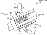
図2を参照すると、一実施形態による、開放構成のユーザインターフェース装置の斜視図が示されている。UID126は、ユーザ、例えば遠隔操作者107によって保持される把持構造体を含むことができる。例えば、UID126は、中央に配置された装置本体204から外側に延在するいくつかのグリップリンク202を含んでもよい。ユーザは、いくつかの指の間にグリップリンク202の一部分を保持し、作業スペース内でUID126を動かすことができる。作業スペースは、ユーザの手の届く範囲であってもよい。 With reference to FIG. 2, a perspective view of an open configuration user interface device according to one embodiment is shown. The UID 126 can include a gripping structure held by a user, such as a remote operator 107. For example, the UID 126 may include several grip links 202 extending outward from the centrally located device body 204. The user can hold a portion of the grip link 202 between several fingers and move the UID 126 within the workspace. The workspace may be within reach of the user.

一実施形態では、装置本体204は、中心軸206に沿って長手方向に延在する。例えば、装置本体204は、ユーザがグリップリンクを保持しているときに、通常はユーザ107の手の中に包まれる近位端208から長手方向に延在してもよい。装置本体204は、前向きの表面を有する遠位端210まで延在してもよい。装置本体204は、いくつかの部分に分割することができる。装置本体204の遠位部分は、中心軸206の周りに延在する外面を有する装置ヘッド212を含み得る。装置ヘッド212の外面は、円筒形であってもよく、空洞を取り囲むことができる。装置ヘッド212内の空洞は、UID126の動きを追跡するために使用される追跡センサ214を受容することができる。より具体的には、追跡センサ214は、装置本体204内に取り付けられてもよい。追跡センサ214は、装置ヘッド212に固定することができ、したがって、追跡センサ214は、装置ヘッド212と同じ動きを経験することができる。 In one embodiment, the device body 204 extends longitudinally along the central axis 206. For example, the device body 204 may extend longitudinally from the proximal end 208, which is normally wrapped in the hands of the user 107, while the user is holding the grip link. The device body 204 may extend to the distal end 210 with a forward facing surface. The device body 204 can be divided into several parts. The distal portion of the device body 204 may include a device head 212 having an outer surface extending around a central axis 206. The outer surface of the device head 212 may be cylindrical and may surround the cavity. The cavity within the device head 212 is capable of receiving a tracking sensor 214 used to track the movement of the UID 126. More specifically, the tracking sensor 214 may be mounted within the device body 204. The tracking sensor 214 can be fixed to the device head 212, so that the tracking sensor 214 can experience the same movements as the device head 212.

後述するように、追跡センサ214は、UID126の装置本体の動きを追跡し、外科用ツールの動作を制御するための入力空間状態信号を生成するように構成することができる。入力空間状態信号は、装置本体204の動きに応答して生成され得る。追跡センサ214は、ユーザ107がUID126を動かすときに、装置本体204の位置及び/又は向きを検出することができ、検出された位置及び/又は向きは、外科用ロボットシステム100の制御に相関させることができる。例えば、追跡センサ214は、作業スペース内の装置本体204の、いくつかの自由度での動作、例えば、1つ以上の方向への並進、1つ以上の軸の周りでの回転、又は1つ以上の軸に対する傾きを検出してもよい。追跡センサ214は、加速度計及び/又はジャイロスコープ又は他の慣性センサを含んでもよい。追跡センサ214は、6つの自由度の位置センサを含んでもよい。例えば、位置センサは、周囲の磁場に応答するパラメータを有し、かつセンサの位置又は向きを決定するために例えば追跡システムによって測定可能なパラメータを有する、例えばコイルなどの構成要素を含む電磁追跡センサであり得る。追跡センサ214は、センサの位置又は向きを決定するために画像内で識別可能なマーカパターンを有する光学追跡構成要素を含んでもよい。追跡システムは、ユーザコンソール120に組み込まれてもよく、有線又は無線リンクによって追跡センサ214に接続されてもよい。作業スペース内のUID126の検出された運動は、エンドエフェクタ又はツールのグリップ動作又は把持動作などの、対応する運動、例えば、外科用ロボットシステム100の、把持具の把持運動又はジョーの把持運動などの、対応する運動を引き起こすことができる。 As will be described later, the tracking sensor 214 can be configured to track the movement of the device body of the UID 126 and generate an input spatial state signal to control the movement of the surgical tool. The input space state signal can be generated in response to the movement of the device body 204. The tracking sensor 214 can detect the position and / or orientation of the device body 204 when the user 107 moves the UID 126, and the detected position and / or orientation correlates with the control of the surgical robot system 100. be able to. For example, tracking sensor 214 may operate the device body 204 in the workspace in several degrees of freedom, eg, translation in one or more directions, rotation around one or more axes, or one. The inclination with respect to the above axes may be detected. Tracking sensor 214 may include an accelerometer and / or a gyroscope or other inertial sensor. Tracking sensor 214 may include a position sensor with six degrees of freedom. For example, a position sensor is an electromagnetic tracking sensor that includes components such as coils that have parameters that respond to an ambient magnetic field and that have parameters that can be measured, for example, by a tracking system to determine the position or orientation of the sensor. Can be. Tracking sensor 214 may include an optical tracking component having a marker pattern identifiable in the image to determine the position or orientation of the sensor. The tracking system may be integrated into the user console 120 and may be connected to the tracking sensor 214 by a wired or wireless link. The detected motion of the UID 126 in the workspace is a corresponding motion, such as a grip or grip motion of an end effector or tool, such as a gripping motion of a gripping tool or a gripping motion of a jaw of a surgical robot system 100. , Can trigger the corresponding movement.

外科用ツール104及び/又はアーム112を制御するために遠隔操作者107によって取り扱われるUID126は、人間工学的であり得る。例えば、UID126は、互いに角度をなして中心軸206から径方向外側に延在する、いくつかの、例えば、少なくとも3つのグリップリンク202を含むことができる。したがって、ユーザ107は、伸ばされた親指、人差し指、及び中指の間でグリップリンク202を快適に保持することができる。各グリップリンクは、ユーザ107の指によって押される外側グリップ面を有するグリップクランク216を含むことができる。グリップクランク216は、対応する枢軸(図5)で装置本体204に枢動可能に連結されてもよく、これにより、ユーザ107の指によってグリップクランク216に加えられる圧力は、グリップクランク216を装置本体204に向かって径方向内側に動かすことができる。例えば、グリップリンク202は、近位端208の近くで装置本体204に接続され得る。 The UID 126 handled by the remote operator 107 to control the surgical tool 104 and / or the arm 112 can be ergonomic. For example, the UID 126 may include several, eg, at least three grip links 202, extending radially outward from the central axis 206 at an angle to each other. Therefore, the user 107 can comfortably hold the grip link 202 between the extended thumb, index finger, and middle finger. Each grip link can include a grip crank 216 having an outer grip surface that is pushed by the finger of user 107. The grip crank 216 may be pivotally coupled to the device body 204 at the corresponding pivot (FIG. 5) so that the pressure exerted on the grip crank 216 by the finger of the user 107 causes the grip crank 216 to be pivotally connected to the device body 204. It can be moved inward in the radial direction toward 204. For example, the grip link 202 may be connected to the device body 204 near the proximal end 208.

グリップクランク216の動きは、グリップリンク202の他の構成要素の動きを引き起こし得る。各グリップリンク202は、スライダクランク機構であってもよく、グリップリンク202は、装置本体204に連結された接地(グリップクランク216の枢軸)を有し得る。各グリップリンク202は、対応する枢軸においてグリップクランク216に枢動可能に連結された従動アーム218を含み得る。更に、従動アーム218は、グリップクランク216からスライダ220まで径方向内側に延在することができる。従動アーム218は、対応する枢動継手においてスライダ220に枢動可能に連結され得る。グリップクランク216は、ピボット継手で装置本体204に接地されてもよいが、スライダ220は、装置本体204に摺動可能に連結されてもよい。 The movement of the grip crank 216 can cause the movement of other components of the grip link 202. Each grip link 202 may be a slider crank mechanism, which may have a ground (the pivot of the grip crank 216) connected to the device body 204. Each grip link 202 may include a driven arm 218 pivotally coupled to a grip crank 216 at the corresponding axis. Further, the driven arm 218 can extend radially inward from the grip crank 216 to the slider 220. The driven arm 218 may be pivotally coupled to the slider 220 at the corresponding pivot joint. The grip crank 216 may be grounded to the device body 204 with a pivot joint, but the slider 220 may be slidably connected to the device body 204.

図3を参照すると、一実施形態による、開放構成のユーザインターフェース装置の側面図が示されている。スライダ220は、装置本体204のシャフト部分に摺動可能に連結されてもよい。シャフト部分は、本体表面302を含むことができ、スライダ220は本体表面302に取り付けられてもよい。例として、スライダ220は、本体表面302の外形よりわずかに大きい断面輪郭を含む内側チャネルを有するカラーであってもよい。カラーは、スライダ本体の継手においてスライダ220を装置本体204に接続するために、本体表面302上に摺動嵌合を有してもよい。したがって、スライダ220は、装置本体204の遠位端210と近位端208との間で中心軸206に沿って動くことができる。 With reference to FIG. 3, a side view of an open configuration user interface device according to one embodiment is shown. The slider 220 may be slidably connected to the shaft portion of the apparatus main body 204. The shaft portion may include a body surface 302, and the slider 220 may be attached to the body surface 302. As an example, the slider 220 may be a collar with an inner channel containing a cross-sectional contour slightly larger than the outer shape of the body surface 302. The collar may have a sliding fit on the body surface 302 to connect the slider 220 to the device body 204 in the fitting of the slider body. Therefore, the slider 220 can move along the central axis 206 between the distal end 210 and the proximal end 208 of the device body 204.

グリップリンク202は、同じスライダ220を共有することができる。例えば、グリップ機構は、3つ以上の相互接続されたグリップリンク202のアレイを有してもよい。相互接続されたグリップリンク202は、それぞれの接地において装置本体204に接続されたそれぞれのグリップクランク216を有することができ、グリップリンク202は、同じスライダ220に接続されたそれぞれの従動アーム218を有することができる。したがって、グリップクランク216のうちの1つが装置本体204に向かって径方向内側に動くと、対応するグリップリンク202は、スライダ220を遠位に押して、他のグリップクランク216を装置本体204に向かって引っ張ることができる。すなわち、グリップリンク202は、任意の1つのグリップクランク216の作動が、グリップクランク216の全ての作動及びスライダ220の対応する動きをもたらすように相互接続されてもよい。 The grip link 202 can share the same slider 220. For example, the grip mechanism may have an array of three or more interconnected grip links 202. The interconnected grip links 202 can have their respective grip cranks 216 connected to the device body 204 at their respective grounds, and the grip links 202 have their respective driven arms 218 connected to the same slider 220. be able to. Thus, when one of the grip cranks 216 moves radially inward towards the device body 204, the corresponding grip link 202 pushes the slider 220 distally and the other grip crank 216 towards the device body 204. Can be pulled. That is, the grip link 202 may be interconnected such that the actuation of any one grip crank 216 results in all actuation of the grip crank 216 and the corresponding movement of the slider 220.

スライダ220の動作は、バイアス要素304によって抵抗されてもよい。バイアス要素304は、互いに対して動くことができる第1の端部306及び第2の端部308を有することができる。バイアス要素は、受動的又は能動的要素とすることができる。例えば、バイアス要素304は、互いに対して動く端部を有する戻りばねなどの受動的要素であってもよい。戻りばねは、ばねの取り付け位置に応じて圧縮ばね又は引張ばねであり得る。例えば、戻りばねの端部は、互いに向かって(例えば、圧縮ばねの場合にばねがエネルギーを蓄えているとき、又は引張ばねの場合にばねがエネルギーを放出しているとき)、及び互いから離れて(例えば、圧縮ばねの場合にばねがエネルギーを放出しているとき、又は引張ばねの場合にばねがエネルギーを蓄えているとき)動くことができる。戻りばねは、装置本体204とスライダ220との間で予荷重をかけられ得る。例えば、バイアス要素304の第1の端部306は、装置ヘッド212の近位面に押し付けられてもよく、又は別の方法で接続されてもよく、第2の端部308は、スライダ220の遠位面に押し付けられてもよく、又は別の方法で接続されてもよい。バイアス要素304は、スライダ220を第1の端部306に向かって、及び/又は第1の端部306から離れるように動かすことができる。例えば、バイアス要素304が圧縮ばねであり、ユーザ107がグリップクランク216を閉位置まで握ったとき、ユーザ107がグリップクランク216を介抱すると、バイアス要素304は、拡張してスライダ220を近位に押し、グリップクランク216を開位置に向かって径方向外向きに押し進めることができる。同様に、バイアス要素304がスライダ220の近位面と近位端208との間に取り付けられた引張ばねであるとき、バイアス要素304は、グリップリンク202の閉鎖構成における移動終了位置から、グリップリンク202の開放構成における開位置までスライダ220を引っ張ることができる。より具体的には、ユーザ107がグリップクランク216を閉位置から解放すると、バイアス要素304は、スライダ220及びグリップリンク202を開位置に押し進めることができる。 The operation of the slider 220 may be resisted by the bias element 304. The bias element 304 can have a first end 306 and a second end 308 that can move relative to each other. The bias element can be a passive or active element. For example, the bias element 304 may be a passive element such as a return spring having ends that move relative to each other. The return spring can be a compression spring or a tension spring, depending on the mounting position of the spring. For example, the ends of the return springs are toward each other (eg, when the spring is storing energy in the case of a compression spring, or when the spring is releasing energy in the case of a tension spring) and away from each other. It can move (for example, when the spring is releasing energy in the case of a compression spring, or when the spring is storing energy in the case of a tension spring). The return spring can be preloaded between the device body 204 and the slider 220. For example, the first end 306 of the bias element 304 may be pressed against the proximal surface of the device head 212 or may be connected in another way, the second end 308 of the slider 220. It may be pressed against the distal surface or connected in another way. The bias element 304 can move the slider 220 towards and / or away from the first end 306. For example, when the bias element 304 is a compression spring and the user 107 grips the grip crank 216 to the closed position and the user 107 holds the grip crank 216, the bias element 304 expands and pushes the slider 220 proximally. , The grip crank 216 can be pushed outward in the radial direction toward the open position. Similarly, when the bias element 304 is a tension spring mounted between the proximal surface and the proximal end 208 of the slider 220, the bias element 304 is a grip link from the end of movement position in the closed configuration of the grip link 202. The slider 220 can be pulled to the open position in the open configuration of 202. More specifically, when the user 107 releases the grip crank 216 from the closed position, the bias element 304 can push the slider 220 and the grip link 202 into the open position.

一実施形態では、バイアス要素304は、装置本体204に接続された第1の端部306及びスライダ220に接続された第2の端部308を有する線形アクチュエータなどの能動的要素である。線形アクチュエータは、UID126のコアに取り付けられたリニアモータを含むことができる。リニアモータは、スライダ220を装置ヘッド212に対して遠位及び近位に動かすために、第1の端部306及び第2の端部308を、互いに向かって又は互いから離れるように駆動することができる。戻りばねに関して上述したように、線形アクチュエータは、ユーザ107がグリップクランク216を閉位置から解放するときに、スライダ220及びグリップリンク202を開位置に向かって動かすために、スライダ220に復元力を及ぼすことができる。更に、線形アクチュエータは、ユーザ107に力フィードバックを提供することができる。ユーザに提供される力フィードバック又は動きは、標的組織部位に加えられるグリップ力に対応する触覚フィードバック機構、例えば触覚フィードバックであり得る。スライダ220に対して駆動することにより、線形アクチュエータは、グリップクランク216が何かを握っているという感覚をユーザ107に与えることができる。より具体的には、線形アクチュエータは、ユーザが例えば鉗子で患者102の組織を手動で握った場合にユーザ107が感じる抵抗をシミュレートする抵抗力を提供することができる。線形アクチュエータは、ユーザによって組織に加えられる力の量を示すために、ある量の力でグリップクランク216をユーザの指に対して駆動することができる。したがって、ユーザ107は、グリップリンク202を介して線形アクチュエータによってユーザの指に加えられる反力に基づいて、器具が組織に加えている力の量を知ることができる。 In one embodiment, the bias element 304 is an active element such as a linear actuator having a first end 306 connected to the device body 204 and a second end 308 connected to the slider 220. The linear actuator can include a linear motor mounted on the core of the UID 126. The linear motor drives the first end 306 and the second end 308 towards or away from each other in order to move the slider 220 distally and proximally to the device head 212. Can be done. As mentioned above with respect to the return spring, the linear actuator exerts a restoring force on the slider 220 to move the slider 220 and the grip link 202 towards the open position when the user 107 releases the grip crank 216 from the closed position. be able to. In addition, the linear actuator can provide force feedback to user 107. The force feedback or movement provided to the user can be a tactile feedback mechanism corresponding to the grip force applied to the target tissue site, such as tactile feedback. By driving with respect to the slider 220, the linear actuator can give the user 107 the sensation that the grip crank 216 is gripping something. More specifically, the linear actuator can provide a resistance that simulates the resistance felt by the user 107 when the user manually grasps the tissue of the patient 102, for example with forceps. The linear actuator can drive the grip crank 216 against the user's finger with a certain amount of force to indicate the amount of force applied to the tissue by the user. Thus, the user 107 can know the amount of force the instrument is exerting on the tissue based on the reaction force applied to the user's finger by the linear actuator via the grip link 202.

図4を参照すると、一実施形態による、開放構成のユーザインターフェース装置の端面図が示されている。各グリップクランク216は、装置本体204から、それぞれの平面402に沿って延在し得る。平面402は長手方向に延在し、中心軸206に平行な線に沿って交差することができる。例えば、平面402は、中心軸206に沿って交差してもよい。一実施形態では、グリップリンク202は、中心軸206を中心として回転対称である。したがって、平面402は、中心軸206を中心に等角であり得る。例として、図4に示されるように、UID126が6つのグリップリンク202の円形アレイを含む場合、グリップリンク202は、60度の角度で互いから周方向に分離された6つの平面402に沿って分散されてもよい。したがって、グリップ構造体は、中心軸206に対して径方向に対称な機構である。 
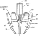
With reference to FIG. 4, an end view of an open configuration user interface device according to one embodiment is shown. Each grip crank 216 may extend from the device body 204 along its respective plane 402. The plane 402 extends longitudinally and can intersect along a line parallel to the central axis 206. For example, the plane 402 may intersect along the central axis 206. In one embodiment, the grip link 202 is rotationally symmetric about a central axis 206. Therefore, the plane 402 can be isometric about the central axis 206. As an example, as shown in FIG. 4, if the UID 126 contains a circular array of six grip links 202, the grip links 202 are along six planes 402 that are circumferentially separated from each other at an angle of 60 degrees. It may be dispersed. Therefore, the grip structure is a mechanism that is radially symmetrical with respect to the central axis 206.

UID126のグリップリンク202は、対称セットに分割されてもよい。一実施形態では、グリップ構造体は、中心軸206の周りに均一に分散されたグリップリンクの第1のセット404を含む。より具体的には、グリップリンクの第1のセット404は、3つ以上のグリップリンク202の第1の円形アレイであってもよい。第1のセットが3つのグリップリンク202を含むとき、各グリップリンク202のそれぞれのグリップクランク216は、他の平面402から120度離れているそれぞれの平面402に沿って延在してもよい。UID126は、グリップリンクの第2のセット406を含むことができる。グリップリンクの第2のセット406は、中心軸206の周りに均一に分散され得る。グリップリンクの第2のセット406は、3つ以上のグリップリンク202の第2の円形アレイであってもよく、第2の円形アレイは、グリップリンクの第1のセット404の第1の円形アレイと比較すると、中心軸206に対して交互に配置され得る。より具体的には、第2のセットの各グリップクランク216は、第1のセットの一対の隣接するグリップクランク216の間に延在してもよい。したがって、第2のセット406は、グリップリンクの第1のセット404のそれぞれの平面402の間で装置本体204から延在する少なくとも1つのグリップクランク216を含む。以下に記載されるように、グリップリンクの各セットは、外科用ロボットシステム100の異なる非グリップ機能を制御するために使用される信号を生成することができる。それにもかかわらず、セットは、ユーザ107がグリップクランク216のいずれかを握ったときに、外科用ロボットシステム100のグリップ機能を制御するための信号を生成するために一斉に開閉してもよい。つまり、ユーザ107がグリップクランク216を握ると、グリップリンク202は、閉位置に向かって動くことができ、中心軸206に沿ったスライダ220の位置が変わり可能性がある。スライダ位置の変化は、グリッパ制御信号の対応する出力を引き起こすための入力として検出されてもよい。 The grip link 202 of the UID 126 may be divided into symmetrical sets. In one embodiment, the grip structure comprises a first set of grip links 404 that are evenly distributed around a central axis 206. More specifically, the first set of grip links 404 may be a first circular array of three or more grip links 202. When the first set includes three grip links 202, each grip crank 216 of each grip link 202 may extend along each plane 402 120 degrees away from the other plane 402. The UID 126 can include a second set of grip links 406. A second set of grip links 406 may be evenly distributed around the central axis 206. The second set 406 of the grip links may be a second circular array of three or more grip links 202, the second circular array being the first circular array of the first set 404 of the grip links. Can be arranged alternately with respect to the central axis 206. More specifically, each grip crank 216 in the second set may extend between a pair of adjacent grip cranks 216 in the first set. Thus, the second set 406 includes at least one grip crank 216 extending from the device body 204 between the respective planes 402 of the first set 404 of the grip link. As described below, each set of grip links can generate signals used to control different non-grip functions of the surgical robot system 100. Nevertheless, the set may open and close all at once to generate a signal to control the grip function of the surgical robot system 100 when the user 107 grips any of the grip cranks 216. That is, when the user 107 grips the grip crank 216, the grip link 202 can move toward the closed position, and the position of the slider 220 along the central axis 206 may change. The change in slider position may be detected as an input to trigger the corresponding output of the gripper control signal.

図5を参照すると、一実施形態による、開放構成のユーザインターフェース装置の、図3の線5−5について取った断面図が示されている。UID126の各グリップリンク202は、共通のスライダ220によって相互接続されたスライダクランク機構であり得る。上述したように、グリップクランク216は、装置クランク継手502において近位端208付近の装置本体204に接続されてもよい。装置クランク継手502は、グリップクランク216が中心軸206に対して径方向内側及び径方向外側に枢動することを可能にするために、単一の自由度(枢軸を中心とする回転)を有する回転継手504であってもよい。従動アーム218は、グリップクランク216とスライダ220との間を橋渡しすることができる。より具体的には、従動アーム218は、従動クランク継手506においてグリップクランク216に接続されてもよく、従動アーム218は、従動スライダ継手508においてスライダ220に接続されてもよい。装置クランク継手502のように、従動クランク継手506及び従動スライダ継手508は、従動アーム218が中心軸206に対して枢動及び角度変更できるように、回転継手504であり得る。例えば、従動アーム218が中心軸206に対してより平行な向きに枢動すると、スライダ220は、装置本体204の本体表面302に沿って遠位に前進してもよい。対照的に、従動アーム218が中心軸とアーム218の長さとの間の角度を増加させる向きに枢動すると、スライダ220は、本体表面302に沿って近位に前進してもよい。 With reference to FIG. 5, a cross-sectional view taken along line 5-5 of FIG. 3 of an open configuration user interface device according to one embodiment is shown. Each grip link 202 of the UID 126 may be a slider crank mechanism interconnected by a common slider 220. As described above, the grip crank 216 may be connected to the device body 204 near the proximal end 208 in the device crank joint 502. The device crank joint 502 has a single degree of freedom (rotation about the pivot) to allow the grip crank 216 to pivot radially inward and radially outward with respect to the central axis 206. It may be a rotary joint 504. The driven arm 218 can bridge between the grip crank 216 and the slider 220. More specifically, the driven arm 218 may be connected to the grip crank 216 in the driven crank joint 506, and the driven arm 218 may be connected to the slider 220 in the driven slider joint 508. Like the device crank fitting 502, the driven crank fitting 506 and the driven slider fitting 508 can be rotary fittings 504 so that the driven arm 218 can pivot and angle with respect to the central axis 206. For example, if the driven arm 218 pivots in a direction more parallel to the central axis 206, the slider 220 may advance distally along the body surface 302 of the device body 204. In contrast, the slider 220 may advance proximally along the body surface 302 when the driven arm 218 is pivoted in a direction that increases the angle between the central axis and the length of the arm 218.

本体表面302は、装置シャフト516の外面であってもよい。装置シャフト516は、装置ヘッド212と近位端208との間に延在する装置本体204の円筒形シャフト部分であり得る。装置シャフト516は、中心軸206に沿って延在することができ、したがって、本体表面302は、中心軸206の周りに延在してもよい。スライダ220は、中心軸206の周りに延在するカラーを含んでもよい。スライダ220と本体表面302との間の境界は、プリズム継手514とすることができる。より具体的には、スライダ220は、スライダ本体継手512において本体表面302に接続されてもよく、スライダ本体継手512は、プリズム継手514であってもよい。中心軸206を中心としたスライダ220の回転は、従動アーム218によって制約を受けてもよく、したがって、スライダ220は、中心軸206に沿って単一の自由度(軸方向)を有し得る。 The body surface 302 may be the outer surface of the device shaft 516. The device shaft 516 can be a cylindrical shaft portion of the device body 204 that extends between the device head 212 and the proximal end 208. The device shaft 516 can extend along the central axis 206, and thus the body surface 302 may extend around the central axis 206. The slider 220 may include a collar that extends around the central axis 206. The boundary between the slider 220 and the main body surface 302 can be a prism joint 514. More specifically, the slider 220 may be connected to the main body surface 302 in the slider main body joint 512, and the slider main body joint 512 may be a prism joint 514. The rotation of the slider 220 about the central axis 206 may be constrained by the driven arm 218, so the slider 220 may have a single degree of freedom (axial) along the central axis 206.

中心軸206に沿ったスライダ220の変位を監視することができる。一実施形態では、UID126は、グリップリンク変位センサ518を含む。変位センサ518は、本体表面302上のスライダ220の位置又は動きを検出及び/又は測定する変位検出センサとすることができる。例えば、グリップリンク変位センサ518は、スライダ220の遠位面に向かって放射エネルギーを放射する光学変位センサであってもよい。グリップリンク変位センサ518は、遠位表面から反射されたエネルギーを検出することができる。センサは、受信されたエネルギーに基づいて、スライダ220の遠位面と装置ヘッド212との間の長手方向距離を決定することができる。より具体的には、グリップリンク変位センサ518は、光学的感知技術を使用して、本体表面302上のスライダ220の軸方向位置を決定することができる。他のセンサタイプを使用して、装置シャフト516上のスライダ220の軸方向位置を決定することができる。グリップリンク変位センサ518は、スライダ220の変位又は位置に基づいて出力信号を生成するように構成されてもよい。出力信号はグリップ信号と呼ばれることがあり、スライダ220の動きがグリップクランク216の動きに対応することを前提として、グリップ信号は、グリップリンク202の動きに応答して生成されてもよい。したがって、ユーザ107がグリップリンク202を握ると、グリップ信号が生成され、外科用ツール104の一部分、例えば把持具のジョーの動きを制御するために、グリップ信号が生成され、外科用ロボットシステム101に出力され得る。グリップリンク変位センサ518は、装置本体204内に取り付けられた他の電子機器に電気的に接続されてもよい。例えば、装置本体204内の電源は、グリップリンク変位センサ518に電力を供給することができる。同様に、グリップリンク変位センサ518は、装置本体204内に取り付けられたUIDプロセッサ520にデータを通信することができる。UIDプロセッサ520は、センサデータを処理し、対応する信号、例えばグリップ信号を、コンピュータシステム110に通信することができる。 The displacement of the slider 220 along the central axis 206 can be monitored. In one embodiment, the UID 126 includes a grip link displacement sensor 518. The displacement sensor 518 can be a displacement detection sensor that detects and / or measures the position or movement of the slider 220 on the surface 302 of the main body. For example, the grip link displacement sensor 518 may be an optical displacement sensor that radiates radiant energy toward the distal surface of the slider 220. The grip link displacement sensor 518 can detect the energy reflected from the distal surface. The sensor can determine the longitudinal distance between the distal surface of the slider 220 and the device head 212 based on the energy received. More specifically, the grip link displacement sensor 518 can use optical sensing techniques to determine the axial position of the slider 220 on the body surface 302. Other sensor types can be used to determine the axial position of the slider 220 on the device shaft 516. The grip link displacement sensor 518 may be configured to generate an output signal based on the displacement or position of the slider 220. The output signal is sometimes referred to as a grip signal, and the grip signal may be generated in response to the movement of the grip link 202, assuming that the movement of the slider 220 corresponds to the movement of the grip crank 216. Therefore, when the user 107 grips the grip link 202, a grip signal is generated, and a grip signal is generated to control the movement of a part of the surgical tool 104, for example, the jaw of the gripper, to the surgical robot system 101. Can be output. The grip link displacement sensor 518 may be electrically connected to other electronic devices mounted within the device body 204. For example, the power supply in the apparatus main body 204 can supply power to the grip link displacement sensor 518. Similarly, the grip link displacement sensor 518 can communicate data to the UID processor 520 mounted in the device body 204. The UID processor 520 can process sensor data and communicate corresponding signals, such as grip signals, to the computer system 110.

UID126は、UIDプロセッサ520を含む様々な電子機器を受容するための内部容積を含んでもよい。UIDプロセッサ520は、容量センサとインターフェース接続するために使用される感知増幅器回路及びアナログデジタル変換回路、並びにプログラム可能な論理又はプログラム可能なデジタルプロセッサを含む論理回路を含む、アナログ信号処理及びデジタル信号処理用の回路を包含してもよい。UIDプロセッサ520は、UIDプロセッサ520を、デバイスセンサ、例えば、追跡センサ214又はグリップリンク変位センサ518に接続するための様々なセンサ端子を有するプリント回路基板上に取り付けられ得る。電池は、プリント回路基板上に取り付けられて、UID126の電子部品に電力を供給することができる。電線(図示せず)は、UID126の各構成要素の中央ボアを通って中心軸206に沿って延在して、UIDプロセッサ520に接続することができる。例えば、電線は、中心軸206に沿って、追跡センサ214又はグリップリンク変位センサ518から装置シャフト516及び装置ヘッド212を通って延在して、UIDプロセッサ520又はプリント回路基板上の端子に取り付けることができる。UIDプロセッサ520は、他のセンサ、例えば、導電パッド又は指クラッチ(図8)に電気的に接続されてもよい。電線は、接地端子と比較することができる、静電容量信号をUIDプロセッサ520に伝導してもよい。接地端子は、UIDプロセッサ520又はプリント回路基板上にあってもよい。したがって、UIDプロセッサ520は、以下に説明する機能をトリガするために、導電パッド又は指クラッチの静電容量の変化を検出するように構成されてもよい。 The UID 126 may include an internal volume for receiving various electronic devices including the UID processor 520. The UID processor 520 includes analog and digital signal processing, including sensing amplifier circuits and analog-to-digital conversion circuits used to interface with capacitive sensors, as well as logic circuits that include programmable logic or programmable digital processors. Circuits may be included. The UID processor 520 may be mounted on a printed circuit board having various sensor terminals for connecting the UID processor 520 to a device sensor, such as a tracking sensor 214 or a grip link displacement sensor 518. The battery can be mounted on a printed circuit board to power the electronic components of the UID 126. An electric wire (not shown) can extend along the central axis 206 through the central bore of each component of the UID 126 and connect to the UID processor 520. For example, the wires extend along the central axis 206 from tracking sensor 214 or grip link displacement sensor 518 through device shaft 516 and device head 212 and attach to terminals on the UID processor 520 or printed circuit board. Can be done. The UID processor 520 may be electrically connected to another sensor, such as a conductive pad or finger clutch (FIG. 8). The wire may conduct a capacitance signal to the UID processor 520, which can be compared to the ground terminal. The ground terminal may be on the UID processor 520 or the printed circuit board. Therefore, the UID processor 520 may be configured to detect a change in capacitance of the conductive pad or finger clutch to trigger the functions described below.

図6を参照すると、一実施形態による、閉鎖構成のユーザインターフェース装置の斜視図が示されている。ユーザ107がグリップクランク216を閉位置に握ると、グリップクランク216の横方向に面する表面は互いに当接することができる。当接するグリップクランクは、組み合わされて概ね球状の外側輪郭を形成する外面を有することができる。より具体的には、グリップクランク216の外面を画定する外側エンベロープは、1つ以上の丸みを帯びた又は球状の表面輪郭を有することができる。例えば、エンベロープは、概ね卵形であってもよく、又は楕円体であってもよい。閉鎖構成では、UID126は、各グリップクランク216上に位置する隆起部の組み合わせによって形成された周方向隆起部602を有してもよい。隆起部602は、触覚データ、すなわち、既知のグリップ位置を示す特徴を提供することができる。すなわち、隆起部602は、ユーザのグリップのための基準特徴部とすることができる。 With reference to FIG. 6, a perspective view of a closed user interface device according to one embodiment is shown. When the user 107 grips the grip crank 216 in the closed position, the laterally facing surfaces of the grip crank 216 can abut against each other. The abutting grip cranks can have outer surfaces that are combined to form a generally spherical outer contour. More specifically, the outer envelope defining the outer surface of the grip crank 216 can have one or more rounded or spherical surface contours. For example, the envelope may be generally oval or ellipsoidal. In the closed configuration, the UID 126 may have a circumferential ridge 602 formed by a combination of ridges located on each grip crank 216. The ridge 602 can provide tactile data, i.e., a feature indicating a known grip position. That is, the raised portion 602 can be a reference feature portion for the user's grip.

閉鎖構成におけるグリップクランク216のエンベロープは、中心軸206を中心にして回転する表面輪郭を有する回転表面を含んでもよい。一例では、エンベロープは楕円体を画定し、中心軸206は楕円体の長手方向軸又は長軸であってもよい。周方向隆起部602の前方のエンベロープの一部分は、より短くてもよく、隆起部602の後方のエンベロープの一部分よりも緩やかな輪郭又はテーパを有してもよい。したがって、エンベロープの遠位部分及び近位部分は、UID126の中心軸206が隆起部602が閉鎖構成に位置する横断面と交差する点から測定される、異なる曲率半径を有してもよい。そのような輪郭は、ユーザ107の快適なグリップ面を提供することができる。更に、閉鎖構成におけるグリップクランク216の組み合わされた外面によって提供される回転面は、指の操作により適している可能性がある。すなわち、UID126が閉じられると、回転面により、UID126がユーザ107の指の間で転がされて、ロボットアーム112のエンドエフェクタ及び/又は外科用ツール104のグリッパジョーの捻れ動作を制御する信号を生成することができる。したがって、閉鎖構成におけるUID126の回転面は、外科用ロボットシステム100の非常に器用で正確な動き、及び制御を可能にする。 The envelope of the grip crank 216 in the closed configuration may include a rotating surface having a surface contour that rotates about a central axis 206. In one example, the envelope defines an ellipsoid, and the central axis 206 may be the longitudinal or major axis of the ellipsoid. A portion of the envelope in front of the circumferential ridge 602 may be shorter and may have a gentler contour or taper than a portion of the envelope behind the ridge 602. Therefore, the distal and proximal portions of the envelope may have different radii of curvature measured from the point where the central axis 206 of the UID 126 intersects the cross section where the ridge 602 is located in the closed configuration. Such contours can provide a comfortable grip surface for user 107. In addition, the rotating surface provided by the combined outer surface of the grip crank 216 in a closed configuration may be more suitable for finger manipulation. That is, when the UID 126 is closed, the rotating surface causes the UID 126 to be rolled between the fingers of the user 107 to give a signal to control the twisting motion of the end effector of the robot arm 112 and / or the gripper jaw of the surgical tool 104. Can be generated. Therefore, the rotating surface of the UID 126 in a closed configuration allows for very dexterous and accurate movement and control of the surgical robot system 100.

UID126は、開放された又は部分的な閉鎖構成における非常に器用で正確な動きをもたらす。グリップクランク216の湾曲した外面は、全ての構成でユーザの指の間で転がされてもよく、これは快適なグリップ面を提供することができる。 The UID 126 provides very dexterous and accurate movement in open or partially closed configurations. The curved outer surface of the grip crank 216 may be rolled between the user's fingers in all configurations, which can provide a comfortable grip surface.

図7を参照すると、一実施形態による、ユーザインターフェース装置の双安定ラッチ機構の斜視図が示されている。ユーザ107は、手術が行われている間に、グリップクランク216を一定期間閉位置で維持する必要が生じ得る。例えば、ユーザ107は、外科用ツールのグリッパジョーを、長期間にわたって閉鎖状態でロックする必要が生じ得る。手の疲労を防止するために、UID126は、ユーザ107がロック解除状態、例えば開位置に向けて解放する準備が整うまで、グリップクランク216を閉位置にロックするための双安定ラッチ機構702を含んでもよい。 With reference to FIG. 7, a perspective view of the bistable latch mechanism of the user interface device according to one embodiment is shown. User 107 may need to keep the grip crank 216 in the closed position for a period of time while the surgery is being performed. For example, the user 107 may need to lock the gripper jaw of the surgical tool in a closed state for an extended period of time. To prevent hand fatigue, the UID 126 includes a bistable latch mechanism 702 to lock the grip crank 216 to the closed position until the user 107 is ready to release it into the unlocked state, eg, the open position. But it may be.

UID126は、双安定ラッチ機構702を内部に組み込んでもよい。例えば、双安定ラッチ機構702の構成要素は、スライダ220の内面と装置本体204の外面との間にあってもよく、例えば、装置シャフト516である。したがって、図7は、スライダ220の内面の下にある装置本体204の外面を明らかにする部分断面図であってもよい。 The UID 126 may incorporate a bistable latch mechanism 702 internally. For example, the component of the bistable latch mechanism 702 may be between the inner surface of the slider 220 and the outer surface of the device body 204, for example the device shaft 516. Therefore, FIG. 7 may be a partial cross-sectional view revealing the outer surface of the device body 204 below the inner surface of the slider 220.

双安定ラッチ機構702は、プッシュプッシュ機構を組み込んでもよい。プッシュプッシュ機構は、グリップクランク216が完全に閉じられてから弛緩されたときに、グリップリンク202を閉鎖構成にロックすることができる。プッシュプッシュ機構は、グリップクランク216が閉鎖構成から再び完全に閉じられてから解放されるとき、グリップリンク202をロック解除して、UID126を開放構成へと解放することができる。したがって、双安定ラッチ機構702は、ロックするために握られ、解放するために再び握られる機構であり得る。 The bistable latch mechanism 702 may incorporate a push-push mechanism. The push-push mechanism can lock the grip link 202 into a closed configuration when the grip crank 216 is fully closed and then relaxed. The push-push mechanism can unlock the grip link 202 and release the UID 126 into the open configuration when the grip crank 216 is completely closed and then released from the closed configuration. Thus, the bistable latch mechanism 702 can be a mechanism that is gripped to lock and re-grasped to release.

一実施形態において、双安定ラッチ機構702は、カム706に沿って移動するカム従動子704を含むことができる。カム従動子704及びカム706は、スライダ220又は装置本体204に組み込まれてもよい。しかしながら、カム従動子704及びカム706は、同じ構成要素に組み込まれてはならず、例えば、両方がスライダ220又は装置本体204に組み込まれてはならない。例として、カム706は、装置シャフト516内に一体化されてもよく、カム従動子704は、装置シャフト516の上に乗るスライダ220に取り付けられてもよい。カム従動子704は、スライダ220の内面と装置シャフト516の外面との間に配置することができる。カム従動子704及びカム706は、互いに対して動くことができる。 In one embodiment, the bistable latch mechanism 702 can include a cam follower 704 that moves along the cam 706. The cam follower 704 and cam 706 may be incorporated into the slider 220 or the device body 204. However, the cam follower 704 and cam 706 must not be integrated into the same component, for example, both must not be incorporated into the slider 220 or the device body 204. As an example, the cam 706 may be integrated within the device shaft 516, and the cam follower 704 may be mounted on a slider 220 that rests on the device shaft 516. The cam follower 704 can be arranged between the inner surface of the slider 220 and the outer surface of the device shaft 516. The cam followers 704 and cam 706 can move relative to each other.

カム従動子704は、中心軸206に平行に延在する長手方向カンチレバーを含むことができる。カム従動子704はまた、カンチレバーの端部から中心軸206に向かって径方向内側に延在する突起部を含んでもよい。突起部はカム706内に延在することができる。より具体的には、カム706は、装置シャフト516の外面に形成された溝を含んでもよく、突起部は溝内に配置されてもよい。 The cam follower 704 can include a longitudinal cantilever extending parallel to the central axis 206. The cam follower 704 may also include a protrusion extending radially inward from the end of the cantilever toward the central axis 206. The protrusion can extend within the cam 706. More specifically, the cam 706 may include a groove formed on the outer surface of the device shaft 516, and the protrusion may be arranged in the groove.

カム706の溝は、ループ経路に沿って延在してもよい。例えば、経路は、溝の最近位位置に非ラッチ位置708と、溝の最遠位位置にある移動終了位置710と、最近位位置と最遠位位置との間の溝の位置にラッチ位置712とを有し得る。経路は、非ラッチ位置708から移動終了位置710まで、次いでラッチ位置712まで反時計回り方向に延在することができる。溝に沿って反時計回りの方向に進むと、経路は、非ラッチ位置708で開始点に戻る。したがって、経路は閉鎖経路であってもよい。 The groove of the cam 706 may extend along the loop path. For example, the path has a non-latch position 708 at the most recent position of the groove, a movement end position 710 at the most distal position of the groove, and a latch position 712 at the groove position between the most distal position and the most distal position. And can have. The path can extend counterclockwise from the non-latch position 708 to the movement end position 710 and then to the latch position 712. Proceeding counterclockwise along the groove, the path returns to the starting point at the non-latch position 708. Therefore, the route may be a closed route.

カム従動子704は、グリップリンク202が閉鎖構成と開放構成との間で動くとき、溝の周りを動いてもよい。例えば、カム従動子704は、ユーザ107がグリップリンク202を握ると、非ラッチ位置708、移動終了位置710、及びラッチ位置712の間で動くことができる。開放構成では、グリップクランク216が径方向に延在している状態で、カム従動子704の突起部は、溝の非ラッチ位置708に位置してもよい。ユーザ107が、何本かの指の間でグリップクランク216をつまむと、グリップクランク216は、開放構成(図2)と閉鎖構成(図6)との間で、装置本体204に向かって枢動する。カム従動子704は、UID126が閉鎖構成に移行するとき、非ラッチ位置708と移動終了位置710との間の溝に沿って動くことができる。ユーザ107がグリップクランク216上のグリップを弛緩させ、戻りばね304がスライダ220を付勢することが可能になると、グリップクランク216は、閉位置とロック位置との間で、装置本体204から離れるように枢動する。すなわち、カム従動子704が移動終了位置710からラッチ位置712に動くと、グリップクランク216は、ロック位置まで径方向外側に動く。したがって、グリップクランク216は、ロック位置よりも閉位置にあるときの方が中心軸206に近くてもよい。 The cam follower 704 may move around the groove as the grip link 202 moves between the closed and open configurations. For example, the cam follower 704 can move between the non-latch position 708, the end-of-movement position 710, and the latch position 712 when the user 107 grips the grip link 202. In the open configuration, the protrusion of the cam follower 704 may be located at the non-latch position 708 of the groove with the grip crank 216 extending radially. When the user 107 pinches the grip crank 216 between several fingers, the grip crank 216 pivots toward the device body 204 between the open configuration (FIG. 2) and the closed configuration (FIG. 6). do. The cam follower 704 can move along the groove between the non-latch position 708 and the end-of-movement position 710 as the UID 126 transitions to the closed configuration. When the user 107 relaxes the grip on the grip crank 216 and the return spring 304 can urge the slider 220, the grip crank 216 moves away from the device body 204 between the closed and locked positions. Crank to. That is, when the cam follower 704 moves from the movement end position 710 to the latch position 712, the grip crank 216 moves radially outward to the lock position. Therefore, the grip crank 216 may be closer to the central axis 206 when it is in the closed position than in the locked position.

グリップリンク202は、グリップクランク216が閉位置又はロック位置のいずれかにあるとき、閉鎖構成にあってもよい。グリップクランク216の閉位置からロック位置への径方向の移動は、無視できるほどであり得る。例えば、グリップクランク216の外面は、結合して、閉位置及びロック位置の両方において楕円体エンベロープを形成してもよい。しかしながら、ロック位置では、ユーザ107は、グリップリンク202を閉鎖構成に維持するためにグリップクランク216を握る必要はない。したがって、ユーザ107は、カム従動子704の突起がラッチ位置712にあるとき、グリップクランク216を捻る又は回転させることによって、UID126を操作することができる。 The grip link 202 may be in a closed configuration when the grip crank 216 is in either the closed or locked position. The radial movement of the grip crank 216 from the closed position to the locked position can be negligible. For example, the outer surfaces of the grip crank 216 may be combined to form an ellipsoidal envelope in both the closed and locked positions. However, in the locked position, the user 107 does not need to grip the grip crank 216 to keep the grip link 202 in the closed configuration. Therefore, the user 107 can operate the UID 126 by twisting or rotating the grip crank 216 when the protrusion of the cam follower 704 is at the latch position 712.

グリップクランク216のラッチを解除するために、ユーザ107は、グリップクランク216を中心軸206に向かって握ることができる。カム従動子704の突起がラッチ位置712にあるときのグリップクランク216の径方向内側への移動は、カム従動子704をカム706の溝に沿って反時計回りの方向に押し進めることができる。突起は、ラッチ位置712の遠位にある第2の移動終了位置714に押し進めることができる。プロングが第2の移動終了位置714にあるとき、グリップクランク216は閉位置にあってもよい。グリップクランク216が閉位置から弛緩すると、カム従動子704は、第2の移動終了位置714と非ラッチ位置708との間の溝をたどることができる。 To release the latch of the grip crank 216, the user 107 can grip the grip crank 216 toward the central axis 206. The radial inward movement of the grip crank 216 when the protrusion of the cam follower 704 is at the latch position 712 can push the cam follower 704 counterclockwise along the groove of the cam 706. The protrusion can be pushed to the second movement end position 714 distal to the latch position 712. The grip crank 216 may be in the closed position when the prong is in the second movement end position 714. When the grip crank 216 is relaxed from the closed position, the cam follower 704 can follow the groove between the second movement end position 714 and the non-latch position 708.

カム706内の溝のセグメントは、カム従動子704を特定の方向に付勢するために、異なる高さにあってもよい。例えば、カム従動子704が第2の移動終了位置714に到達すると、溝の床が降下して、カム従動子704を、第2の移動終了位置714と非ラッチ位置708との間の溝のセグメント上に降下させることができる。カム従動子704が非ラッチ位置708に戻ると、グリップクランク216は再び開位置にあってもよい。開位置において、グリップクランク216は、ロック位置よりも中心軸206から離れている。つまり、グリップクランク216は、開位置よりもロック位置にあるときの方が中心軸206に近くてもよい。 The groove segments within the cam 706 may be at different heights to urge the cam follower 704 in a particular direction. For example, when the cam follower 704 reaches the second movement end position 714, the floor of the groove descends and the cam follower 704 is moved to the groove between the second movement end position 714 and the non-latch position 708. Can be lowered onto a segment. When the cam follower 704 returns to the non-latch position 708, the grip crank 216 may be in the open position again. In the open position, the grip crank 216 is farther from the central axis 206 than in the locked position. That is, the grip crank 216 may be closer to the central axis 206 when it is in the locked position than in the open position.

図7に示され、上記で説明した双安定ラッチ機構702は、グリップリンク202の双安定ラッチを提供する1種類のプッシュプッシュ機構を含む。他のプッシュプッシュ機構を使用してもよい。いずれの場合も、プッシュプッシュ機構は、ユーザ107がグリップクランク216を移動終了まで握ると、それ自体を閉鎖構成にロックし、ユーザ107が再び機構を握ると、グリップクランク216が開位置に向かって解放される機構を含むことができる。 The bistable latch mechanism 702 shown in FIG. 7 and described above includes one type of push-push mechanism that provides a bistable latch for the grip link 202. Other push-push mechanisms may be used. In either case, the push-push mechanism locks itself to the closed configuration when the user 107 grips the grip crank 216 until the end of movement, and when the user 107 grips the mechanism again, the grip crank 216 moves toward the open position. It can include a mechanism to be released.

双安定ラッチ機構702は、UID126の状態をユーザ107に示す機能を含むことができる。例えば、双安定ラッチ機構702は、カム従動子704が移動終了位置710に到達したことを示すスナップ機能を含んでもよい。カム従動子704の突起部が、移動終了位置710でより高い溝床からより低い溝床まで下降するとき、可聴スナップ音、又はスナップに関連する物理的触覚振動が発せられ得る。クリック音又は感覚は、移動終了位置710に到達したことを示すことができる。次に、ユーザ107は、グリップクランク216が解放されて、閉鎖構成でUID126をロックすることができることを知っている。同様のスナップ機能は、グリップクランク216の他の位置に実装されてもよい。例えば、スナップ機能は、カム従動子704が第2の移動終了位置714に達したときにクリックして、UID126がラッチ解除され、グリップクランク216が径方向外側に延在できることをユーザ107に示すことができる。 The bistable latch mechanism 702 can include a function of indicating the state of the UID 126 to the user 107. For example, the bistable latch mechanism 702 may include a snap function indicating that the cam follower 704 has reached the movement end position 710. When the protrusion of the cam follower 704 descends from the higher groove bed to the lower groove bed at the end of movement position 710, an audible snap sound, or a physical tactile vibration associated with the snap, may be emitted. A click sound or sensation can indicate that the movement end position 710 has been reached. User 107 then knows that the grip crank 216 can be released to lock the UID 126 in a closed configuration. A similar snap function may be implemented at other positions on the grip crank 216. For example, the snap function may click when the cam follower 704 reaches the second movement end position 714 to indicate to the user 107 that the UID 126 is unlatched and the grip crank 216 can extend radially outward. Can be done.

外科用器具を用いて手術を行うために、ユーザ107は、外科用ツールのグリッパジョーがいつ完全に閉じられるかを知る必要が生じ得る。例えば、外科用ツールは、グリッパを有するニードルドライバであってもよく、また、閉じるUID126のグリップクランク216は、器具ジョーの閉鎖にマッピングされ得る。したがって、ユーザ107がスナップ機能からのクリックを感じると、器具ジョーが移動終了状態、例えば、完全にクランプされた状態に達したことがユーザ107に通知される。 In order to perform surgery with surgical instruments, user 107 may need to know when the surgical tool gripper jaws are completely closed. For example, the surgical tool may be a needle driver with a gripper, and the grip crank 216 of the closing UID 126 may be mapped to the closing of the instrument jaw. Therefore, when the user 107 feels a click from the snap function, the user 107 is notified that the instrument jaw has reached the end-of-movement state, for example, the fully clamped state.

グリップリンク202の同様のラッチは、上述の線形アクチュエータを使用して行うことができる。例えば、線形アクチュエータは、スライダ220が装置シャフト516に沿って移動終了位置に到達すると判定されたときに作動を停止するように制御されてもよい。ユーザ107がグリップクランク216を再び握ると、スライダ220は移動終了位置まで前進することができ、これは、UIDプロセッサ520によって検出されてもよく、線形アクチュエータは、スライダ220をより近位位置に戻して、グリップクランク216が径方向外側に拡張できるように制御されてもよい。したがって、UID126の双安定ラッチは、機械的及び/又は電気機械的に実行することができる。 A similar latch on the grip link 202 can be performed using the linear actuator described above. For example, the linear actuator may be controlled to stop operation when the slider 220 is determined to reach the end of movement position along the device shaft 516. When the user 107 grips the grip crank 216 again, the slider 220 can advance to the end of movement position, which may be detected by the UID processor 520, where the linear actuator returns the slider 220 to a more proximal position. The grip crank 216 may be controlled so as to expand radially outward. Therefore, the bistability latch of UID126 can be performed mechanically and / or electromechanically.

図8を参照すると、一実施形態による、ユーザインターフェース装置のいくつかのタッチ感知面の側面図が示されている。UID126は、いくつかのタッチ感知面を含むことができる。タッチ感知面は、ユーザ107によるタッチに応答して信号を生成する容量性及び/又は導電性要素を含み得る。したがって、UID126上の所定の位置に触れることにより、ユーザ107は、外科用ロボットシステム100の特定の機能を制御することができる。機能は、非グリップ機能であり得る。 With reference to FIG. 8, a side view of some touch sensing surfaces of the user interface device according to one embodiment is shown. The UID 126 can include several touch sensitive surfaces. The touch-sensitive surface may include a capacitive and / or conductive element that produces a signal in response to a touch by the user 107. Therefore, by touching a predetermined position on the UID 126, the user 107 can control a specific function of the surgical robot system 100. The function can be a non-grip function.

一実施形態では、UID126は、UID126の動きを外科用ロボットシステム100の制御から切り離すためのクラッチ機構を含む。クラッチ機構は、指クラッチと呼ばれることがある。指クラッチは、ユーザ107の指からのタッチによって作動され得るため、このように呼ばれ得る。一実施形態では、指クラッチ802は、点線で示されるように、装置本体204の領域に取り付けられるか、又はこれに一体化されてもよい。例えば、装置ヘッド212は、指クラッチ802を含むことができる。指クラッチ802は、装置ヘッド212のタッチ感知外面を含んでもよく、これにより、ユーザ107は、UID126によって操作されている個々の器具の遠隔操作を休止することが可能になる。つまり、ユーザ107が指クラッチ802に触れると、そのタッチはクラッチ入力として検出されてもよい。クラッチ入力に応答して、追跡センサ214によって検出されたUID126の動きに対応する制御信号を休止することができる。クラッチ入力が取り除かれると(タッチが終了すると)、UID126の動きは、外科用ロボットシステム100の対応する動きを再び引き起こし得る。つまり、例えば指クラッチ802から指を取り除くことによって指クラッチ802のクラッチが外された場合、UIDの動きが再び検出され、運動制御入力として外科用ロボットシステム100に入力されてもよい。 In one embodiment, the UID 126 includes a clutch mechanism for disengaging the movement of the UID 126 from control of the surgical robot system 100. The clutch mechanism is sometimes called a finger clutch. The finger clutch can be so called because it can be actuated by a touch from the finger of the user 107. In one embodiment, the finger clutch 802 may be attached to or integrated with the region of the device body 204, as shown by the dotted line. For example, the device head 212 may include a finger clutch 802. The finger clutch 802 may include a touch-sensitive outer surface of the device head 212, which allows the user 107 to suspend remote control of individual instruments operated by the UID 126. That is, when the user 107 touches the finger clutch 802, the touch may be detected as a clutch input. In response to the clutch input, the control signal corresponding to the movement of the UID 126 detected by the tracking sensor 214 can be deactivated. When the clutch input is removed (when the touch ends), the movement of the UID 126 can re-initiate the corresponding movement of the surgical robot system 100. That is, for example, when the clutch of the finger clutch 802 is disengaged by removing the finger from the finger clutch 802, the movement of the UID may be detected again and input to the surgical robot system 100 as the motion control input.

UID126の指クラッチ802は、作業スペースの限度に達したときに、ユーザ107が作業スペース内にUID126を再配置することを可能にすることができる。例えば、UID126を保持している間にアームを開始位置からある方向に完全に延在させることにより、ユーザ107は、作業スペースの限界、例えば、作業スペースの縁部に到達することができる。作業スペース内でUID126を再配置し、作業空間縁部の方向への更なる移動を可能にするために、ユーザ107は、指クラッチ802に人差し指で触れて、外科用ロボットシステム100をUID126の動きから切り離すことができる。次いで、ユーザ107は、UID126を作業スペース内の開始位置に戻し、人差し指を指クラッチ802から持ち上げることによって、外科用ロボットシステム100のクラッチを外すことができる。次いで、第1の方向への更なる移動は、UID126を動かして外科用ロボットシステム100の動きを操作することによって実行され得る。 The finger clutch 802 of the UID 126 can allow the user 107 to relocate the UID 126 within the workspace when the workspace limit is reached. For example, by fully extending the arm in a direction from the starting position while holding the UID 126, the user 107 can reach the limit of the workspace, eg, the edge of the workspace. In order to rearrange the UID 126 within the workspace and allow further movement towards the edges of the workspace, the user 107 touches the finger clutch 802 with the index finger to move the surgical robot system 100 to the movement of the UID 126. Can be separated from. The user 107 can then disengage the clutch of the surgical robot system 100 by returning the UID 126 to the starting position in the work space and lifting the index finger from the finger clutch 802. Further movement in the first direction can then be performed by moving the UID 126 to manipulate the movement of the surgical robot system 100.

図9を参照すると、一実施形態による、閉鎖構成のユーザインターフェース装置の、図6の線9−9について取った断面図が示されている。指クラッチ802は、導電パッド904の上に取り付けられたクラッチカバー902を含むことができる。導電パッド904は、中心軸206の周りに延在してもよい。例えば、中心軸206は長手方向に延在してもよいが、導電パッド904の外面は、長手方向軸に直交する横断面に沿った経路をたどることができる。経路は、中心軸206の周りに完全に延在してもよく、例えば、横断面上の輪郭は円形であってもよい。あるいは、経路は、中心軸206の周囲に部分的に延在してもよく、例えば、輪郭はC字形であってもよい。一実施形態では、輪郭は、少なくとも270度の角度を超えて広がり、角度は中心軸206を中心として測定される。上述の輪郭は、導電パッド904の単一の横断スライスであってもよく、一実施形態では、輪郭の形状は、導電パッド904の長さにわたって同じであってもよい。すなわち、導電パッド904の長さに沿って取られた導電パッド904の各横断スライスは、円筒状の導電パッド904の場合には、同じ形状、例えば円形であってもよい。 With reference to FIG. 9, a cross-sectional view taken along line 9-9 of FIG. 6 of a closed user interface device according to one embodiment is shown. The finger clutch 802 can include a clutch cover 902 mounted on the conductive pad 904. The conductive pad 904 may extend around the central axis 206. For example, the central axis 206 may extend in the longitudinal direction, but the outer surface of the conductive pad 904 can follow a path along a cross section orthogonal to the longitudinal axis. The path may extend completely around the central axis 206, for example, the contour on the cross section may be circular. Alternatively, the path may partially extend around the central axis 206, for example, the contour may be C-shaped. In one embodiment, the contour extends beyond an angle of at least 270 degrees and the angle is measured about the central axis 206. The contour described above may be a single transverse slice of the conductive pad 904, and in one embodiment the shape of the contour may be the same over the length of the conductive pad 904. That is, each transverse slice of the conductive pad 904 taken along the length of the conductive pad 904 may have the same shape, for example, a circle in the case of the cylindrical conductive pad 904.

図示されていないが、一実施形態では、電線は、一方の端部で導電パッド904を、別の端部で感知増幅器回路(装置本体204内のUIDプロセッサ520の一部)の入力に結合することができる。感知増幅器回路は、電線上の信号に従って変化する感知信号を生成することができる。信号は、導電パッド904へのユーザの指の近接性に基づいて、又は導電パッド904を介した装置ヘッド212のタッチ感知部分へのユーザの指のタッチに基づいて、導電パッド904の静電容量の結果として変化してもよい。UIDプロセッサ520は、感知された信号のデジタル化バージョンを処理して、導電パッド904において静電容量の変化が生じたかどうかを判定することができる。UIDプロセッサ520は、導電パッド904の静電容量の変化を検出することに応答して、クラッチ信号を生成することができる。クラッチ信号は、所定の閾値を上回る導電パッド904上の容量読み取りに応答して生成されてもよい。 Although not shown, in one embodiment, the wire couples the conductive pad 904 at one end to the input of a sensing amplifier circuit (part of the UID processor 520 in the device body 204) at the other end. be able to. The sensing amplifier circuit can generate a sensing signal that changes according to the signal on the wire. The signal is based on the proximity of the user's finger to the conductive pad 904, or based on the user's finger touch to the touch-sensitive portion of the device head 212 via the conductive pad 904, the capacitance of the conductive pad 904. May change as a result of. The UID processor 520 can process the digitized version of the sensed signal to determine if a capacitance change has occurred in the conductive pad 904. The UID processor 520 can generate a clutch signal in response to detecting a change in capacitance of the conductive pad 904. The clutch signal may be generated in response to a capacitance reading on the conductive pad 904 above a predetermined threshold.

導電パッド904は、追跡センサ214の外面とクラッチカバー902の内面との間に配置されてもよい。対照的に、クラッチカバー902は、周囲環境に向かって外向きの外側タッチ面を含んでもよい。ユーザ107の指がクラッチカバー902の外側タッチ面に触れると、指は、クラッチカバー902の壁厚によって導電パッド904から離される。クラッチカバー902は、誘電材料、例えばプラスチックから形成することができ、したがって、ユーザ107の導電性の指が外側タッチ面に触れると、クラッチカバー902の壁にまたがる静電容量は変化する。別の実施形態では、クラッチカバー902は、導電性材料で作ることができる。壁の厚さは、静電容量の変化を確実に検出できるように制限され得る。例えば、内面と外側タッチ面との間のクラッチカバー902の壁厚は、1mm未満であってもよい。したがって、クラッチカバー902及び導電パッド904は、装置ヘッド212において中心軸206上に静電容量センサを提供する。 The conductive pad 904 may be arranged between the outer surface of the tracking sensor 214 and the inner surface of the clutch cover 902. In contrast, the clutch cover 902 may include an outer touch surface that faces outward toward the surrounding environment. When the finger of the user 107 touches the outer touch surface of the clutch cover 902, the finger is separated from the conductive pad 904 by the wall thickness of the clutch cover 902. The clutch cover 902 can be made of a dielectric material such as plastic, so that when the conductive finger of the user 107 touches the outer touch surface, the capacitance across the wall of the clutch cover 902 changes. In another embodiment, the clutch cover 902 can be made of a conductive material. The wall thickness can be limited to reliably detect changes in capacitance. For example, the wall thickness of the clutch cover 902 between the inner surface and the outer touch surface may be less than 1 mm. Therefore, the clutch cover 902 and the conductive pad 904 provide a capacitance sensor on the central axis 206 at the device head 212.

更に図9を参照すると、指クラッチ802は、UID126の通常の把持領域の外側に位置し得る。例えば、指クラッチ802は、通常動作中にユーザが保持するグリップクランク216の外面に対して遠位であり得る。しかしながら、指クラッチ802は、ユーザがUID126を操作しているとき、ユーザ107の指の届く範囲にあり得る。したがって、通常動作中、ユーザ107は指を伸ばして指クラッチ802に触れ、クラッチ信号を外科用ロボットシステム100に送信することができる。 Further referring to FIG. 9, the finger clutch 802 may be located outside the normal grip area of the UID 126. For example, the finger clutch 802 can be distal to the outer surface of the grip crank 216 held by the user during normal operation. However, the finger clutch 802 may be within reach of the user 107's finger when the user is operating the UID 126. Therefore, during normal operation, the user 107 can extend his finger and touch the finger clutch 802 to transmit a clutch signal to the surgical robot system 100.

図8を再び参照すると、追加のタッチ感知領域及び容量センサを使用して、UIDの異なる機能を制御することができる。一実施形態では、UID126は、グリップリンク202のグリップクランク216上に取り付けられた少なくとも1つのグリップクランク容量感知パッド804を含む。例えば、グリップクランク容量感知パッド804は、隆起部602とグリップクランク216の遠位先端との間に、グリップクランク216の外面を含んでもよい。外面のタッチ感知領域は、下にあるグリップクランク容量感知パッド804(図9)を覆うことができる。より具体的には、グリップクランク容量感知パッド804の構成は、上述の指クラッチ802の構造と同様であってもよい。更に、指クラッチ802のように、UIDプロセッサ520は、グリップクランク容量感知パッド804に電気的に結合されて、グリップクランク容量感知パッド804の静電容量の変化を検出することができる。UIDプロセッサ520が所定の閾値を上回る静電容量を検出すると、UIDプロセッサ520は、対応する制御信号を生成することができる。対応する制御信号は、以下で説明する外科用ロボットシステム100のいくつかの所定の機能のうちの1つを制御するために使用されてもよい。 With reference to FIG. 8 again, additional touch sensing areas and capacitance sensors can be used to control different functions of the UID. In one embodiment, the UID 126 includes at least one grip crank capacitance sensing pad 804 mounted on the grip crank 216 of the grip link 202. For example, the grip crank capacitance sensing pad 804 may include an outer surface of the grip crank 216 between the ridge 602 and the distal tip of the grip crank 216. The outer touch sensing area can cover the underlying grip crank capacitance sensing pad 804 (FIG. 9). More specifically, the configuration of the grip crank capacity sensing pad 804 may be the same as the structure of the finger clutch 802 described above. Further, like the finger clutch 802, the UID processor 520 can be electrically coupled to the grip crank capacitance sensing pad 804 to detect a change in capacitance of the grip crank capacitance sensing pad 804. When the UID processor 520 detects a capacitance above a predetermined threshold, the UID processor 520 can generate a corresponding control signal. The corresponding control signal may be used to control one of several predetermined functions of the surgical robot system 100 described below.

UID126は、非常に器用で、指で操作されるものであり、手術中にユーザ107がUID126を落下させる可能性がある。安全上の理由から、インターロックを使用して、UID126が落下したときに意図しない器具の動きを防止することができる。例えば、落下検出センサは、落下時に自由落下状態に入ることに応答して、落下信号を生成することができる。落下検出センサは、UID126の動きを監視し得る追跡センサ214とすることができる。追跡センサ214が、落下状態に対応する動きを検出すると、センサは、インターロックオフ信号を生成して、UID126と外科用ロボットシステム100との間のインターロックを中断又は切断する。 The UID 126 is very dexterous and finger operated, which can allow the user 107 to drop the UID 126 during surgery. For safety reasons, interlocks can be used to prevent unintended movement of the device when the UID 126 is dropped. For example, a fall detection sensor can generate a fall signal in response to entering a free fall state when falling. The fall detection sensor can be a tracking sensor 214 that can monitor the movement of the UID 126. When the tracking sensor 214 detects a movement corresponding to the falling condition, the sensor generates an interlock-off signal to interrupt or break the interlock between the UID 126 and the surgical robot system 100.

一実施形態では、グリップクランク容量感知パッド804の静電容量値に応答してUIDプロセッサ520によって生成された制御信号を使用して、UID126の機能と外科用ロボットシステム100との間のインターロックを制御することができる。より具体的には、グリップクランク容量感知パッド804は、ユーザ107がUID126を保持しているか、又はUID126が落下したかどうかを検出するために使用されてもよい。ユーザ107がUID126を保持しているとき、UID126の動きは、外科用ロボットシステム100の動きに連動することができ、例えば、追跡センサ214によって検出されるUID126の動きは、ロボットアーム112の対応する動きに変換され得る。対照的に、UID126の落下状態が検出されると、UID126と外科用ロボットシステム100との間のインターロックが中断又は切断され得る。 In one embodiment, the control signal generated by the UID processor 520 in response to the capacitance value of the grip crank capacitance sensing pad 804 is used to interlock between the function of the UID 126 and the surgical robot system 100. Can be controlled. More specifically, the grip crank capacitance sensing pad 804 may be used to detect if the user 107 is holding the UID 126 or if the UID 126 has fallen. When the user 107 holds the UID 126, the movement of the UID 126 can be linked to the movement of the surgical robot system 100, for example, the movement of the UID 126 detected by the tracking sensor 214 corresponds to the robot arm 112. Can be converted into movement. In contrast, when a UID 126 drop condition is detected, the interlock between the UID 126 and the surgical robot system 100 can be interrupted or broken.

UIDプロセッサ520は、グリップクランク容量感知パッド804の静電容量を監視して、ユーザ107がUID126を保持しているかどうかを検出することができる。UIDプロセッサ520は、第1のグリップクランク216上のグリップクランク容量感知パッド804及び別のグリップクランク216上の1つ以上の容量感知パッドを連続的に監視することができる。例えば、UIDプロセッサ520は、グリップクランク容量感知パッド804及び第2のグリップクランク216上の第1の容量感知パッド806を監視してもよい。UIDプロセッサ520が、容量感知パッドのうちの1つ以上の静電容量が所定の期間にわたって所定の閾値を下回っていることを検出することに応答して、UIDプロセッサ520は、UID126が落下状態にあると判定することができる。例えば、少なくとも5ミリ秒の間、静電容量が設定閾値を下回ると、UIDプロセッサ520は、インターロックオフ信号を生成することができる。本明細書で使用される場合、用語「インターロックオフ」は、例えば、許容できない事象又は動作に応じて、外科用ロボットシステム100の一部分の遠隔操作が中断されることを意味し得る。UID126は、インターロックオフ信号を外科用ロボットシステム100に送信して、ロボットアーム112及び/又は外科用ツール104の遠隔操作を中断することができる。 The UID processor 520 can monitor the capacitance of the grip crank capacitance sensing pad 804 to detect whether the user 107 is holding the UID 126. The UID processor 520 can continuously monitor the grip crank capacitance sensing pad 804 on the first grip crank 216 and one or more capacitance sensing pads on another grip crank 216. For example, the UID processor 520 may monitor the grip crank capacitance sensing pad 804 and the first capacitance sensing pad 806 on the second grip crank 216. In response to the UID processor 520 detecting that the capacitance of one or more of the capacitance sensing pads is below a predetermined threshold over a predetermined period of time, the UID processor 520 causes the UID 126 to fall. It can be determined that there is. For example, the UID processor 520 can generate an interlock-off signal when the capacitance is below the set threshold for at least 5 milliseconds. As used herein, the term "interlock-off" may mean that remote control of a portion of the surgical robot system 100 is interrupted, for example, in response to an unacceptable event or movement. The UID 126 can transmit an interlock-off signal to the surgical robot system 100 to interrupt remote control of the robot arm 112 and / or the surgical tool 104.

更に図8を参照すると、UID126は、各グリップクランク216の外面上に少なくとも1つの容量感知パッドを含んでもよい。少なくとも1つのグリップクランク216は、外面上にいくつかの容量感知パッドを有してもよい。例えば、グリップクランク216は、第1の容量感知パッド806、第2の容量感知パッド808、及び/又は第3の容量感知パッド810を含んでもよい。容量感知パッドは、グリップクランク216の外面上に順次取り付けられるか又は配置されてもよい。例えば、第1の容量感知パッド806は、外面上で第2の容量感知パッド808の遠位にあってもよく、第2の容量感知パッド808は、第3の容量感知パッド810の遠位にあってもよい。 Further referring to FIG. 8, the UID 126 may include at least one capacitance sensing pad on the outer surface of each grip crank 216. At least one grip crank 216 may have several capacitance sensing pads on the outer surface. For example, the grip crank 216 may include a first capacitance sensing pad 806, a second capacitance sensing pad 808, and / or a third capacitance sensing pad 810. The capacitance sensing pads may be sequentially mounted or placed on the outer surface of the grip crank 216. For example, the first capacitance sensing pad 806 may be distal to the second capacitance sensing pad 808 on the outer surface, and the second capacitance sensing pad 808 may be distal to the third capacitance sensing pad 810. There may be.

一実施形態では、グリップクランク容量感知パッド804の線形アレイは、スワイプジェスチャを検出するために、UIDプロセッサ520によって監視されてもよい。ユーザ107は、グリップクランク216の外面上で指をスワイプすることによって、スワイプジェスチャを入力することができる。スワイプは、第1のグリップクランク容量感知パッド806、第2のグリップクランク容量感知パッド808及び/又は第3のグリップクランク容量感知パッド810のそれぞれの静電容量の変化を引き起こすことができる。UIDプロセッサ520は、パッドのアレイ上でのスワイプジェスチャとして変化のシーケンスを検出することができる。スワイプジェスチャは、様々な出力を制御するために使用されてもよい。例えば、スワイプジェスチャは、制御信号をトリガして、ロボットアーム112に所定の動作を実行させることができる。あるいは、スワイプジェスチャは、ユーザコンソール120のグラフィカルユーザインターフェース(GUI)の一部の要素を制御することができる。例えば、ユーザ107は、メニューをナビゲートし、表示されたビューをスクロールし、表示された画像でズームイン及びズームアウトし、又はGUIの他の態様を制御するための制御入力として、グリップクランク216の外面をスワイプしてもよい。 In one embodiment, the linear array of grip crank capacitance sensing pads 804 may be monitored by the UID processor 520 to detect swipe gestures. The user 107 can input a swipe gesture by swiping a finger on the outer surface of the grip crank 216. Swipes can cause changes in the capacitance of the first grip crank capacitance sensing pad 806, the second grip crank capacitance sensing pad 808 and / or the third grip crank capacitance sensing pad 810, respectively. The UID processor 520 can detect a sequence of changes as a swipe gesture on an array of pads. Swipe gestures may be used to control various outputs. For example, the swipe gesture can trigger a control signal to cause the robot arm 112 to perform a predetermined action. Alternatively, the swipe gesture can control some elements of the graphical user interface (GUI) of the user console 120. For example, user 107 may use the grip crank 216 as a control input for navigating a menu, scrolling the displayed view, zooming in and out on the displayed image, or controlling other aspects of the GUI. You may swipe the outer surface.

グリップクランク216の一部又は全ての容量感知パッドは、追加の機能を制御するために割り当てられてもよい。例えば、UIDプロセッサ520によって検出されたタッチ又はスワイプジェスチャは、制御信号をトリガして、外科用ツール104にエネルギーを送達させることができる。より具体的には、外科用ツール104は、エネルギー器具、例えばレーザ又は紫外線光源であってもよく、所定のタッチ入力は、エネルギー器具の起動をトリガするために検出されてもよい。 Some or all capacitance sensing pads of the grip crank 216 may be assigned to control additional functions. For example, a touch or swipe gesture detected by the UID processor 520 can trigger a control signal to deliver energy to the surgical tool 104. More specifically, the surgical tool 104 may be an energy instrument, such as a laser or UV light source, and a given touch input may be detected to trigger the activation of the energy instrument.

一実施形態では、外科用ツール把持具の開閉を制御するために使用されるグリップクランク216は、GUI制御又はエネルギー送達制御などの他の機能を制御するために使用されるグリップクランク216と交互にすることができる。例として、グリップリンクの第1のセット404を使用して、外科用ツール把持具の開閉を制御することができる。更に、グリップリンクの第1のセット404は、落下検出を提供して、UID126の落下状態を検出し、UID126がユーザ107によって保持されていないときにインターロックオフ信号を送信することができる。対照的に、グリップリンクの第2のセット406を使用して、外科用ロボットシステム100の他の機能を制御することができる。上述したように、第2のセット406のグリップクランク216は、第1のセット404の隣接するグリップクランク216の間に配置されてもよい。したがって、第1のセット404及び第2のセット406のグリップクランク216は、UID126の全ての回転方向においてアクセス可能であり得る。 In one embodiment, the grip crank 216 used to control the opening and closing of the surgical tool grip alternates with the grip crank 216 used to control other functions such as GUI control or energy delivery control. can do. As an example, a first set of grip links 404 can be used to control the opening and closing of the surgical tool grip. In addition, the first set of grip links 404 can provide drop detection to detect the drop state of the UID 126 and transmit an interlock-off signal when the UID 126 is not held by the user 107. In contrast, a second set of grip links 406 can be used to control other functions of the surgical robot system 100. As mentioned above, the grip crank 216 of the second set 406 may be located between the adjacent grip cranks 216 of the first set 404. Therefore, the grip cranks 216 of the first set 404 and the second set 406 may be accessible in all directions of rotation of the UID 126.

追跡センサ214は、装置本体204の動きに応答して空間状態信号を生成するように構成することができる。空間状態信号は、自由空間におけるUID126の位置及び/又は向きに対応し得る。空間状態信号は、ロボットアーム112などの外科用ロボットシステム100の動作を制御することができる。例えば、ユーザ107が作業スペース内でUID126を右方向に動かすと、ロボットアーム112のエンドエフェクタも右方向に動くように制御され得る。同様に、中心軸206を中心にしてUID126を回転させることにより、エンドエフェクタを操作して、対応する長手方向軸を中心に空間内で同様に回転させることができる。 The tracking sensor 214 can be configured to generate a spatial state signal in response to the movement of the device body 204. The spatial state signal may correspond to the position and / or orientation of the UID 126 in free space. The space state signal can control the operation of the surgical robot system 100 such as the robot arm 112. For example, when the user 107 moves the UID 126 to the right in the workspace, the end effector of the robot arm 112 can also be controlled to move to the right. Similarly, by rotating the UID 126 around the central axis 206, the end effector can be manipulated to rotate similarly in space about the corresponding longitudinal axis.

追跡センサ214は、加速度計、ジャイロスコープ、磁力計、又は物理的運動を対応する電気信号に変換することができる1つ以上の他のトランスデューサを含んでもよい。例えば、追跡センサ214は、UID126の物理的変位(例えば、XYZ空間又は他の好適な座標系内での並進)、ロール、ピッチ、及びヨーを含む、6つの自由度を測定することが可能である磁気追跡プローブを含むことができる。一実施形態では、いくつかの追跡センサ214を使用して、UID126の位置及び/又は向きの検出に冗長性を提供する。追跡センサ(単数又は複数)214は、電気信号(単数又は複数)を出力することができ、電気信号(単数又は複数)は、例えば、平均化されて空間状態信号に組み合わせることができる。空間状態信号は、外科用ロボットシステム100の動作を制御するために提供されてもよい。 The tracking sensor 214 may include an accelerometer, a gyroscope, a magnetometer, or one or more other transducers capable of converting physical motion into the corresponding electrical signal. For example, tracking sensor 214 can measure six degrees of freedom, including the physical displacement of the UID 126 (eg, translation in XYZ space or other suitable coordinate system), roll, pitch, and yaw. Certain magnetic tracking probes can be included. In one embodiment, several tracking sensors 214 are used to provide redundancy in the detection of the position and / or orientation of the UID 126. The tracking sensor (s) 214 can output an electrical signal (s) and the electrical signal (s) can be, for example, averaged and combined with a spatial state signal. Spatial state signals may be provided to control the operation of the surgical robot system 100.

UID126を介して入力される制御信号は、有線又は無線接続を通じてコンピュータシステム110に通信されてもよい。一実施形態では、電線は、例えば遠位端210などのUID126の遠位端から延在して、UID126をコンピュータシステム110に接続する。電線は、UID126に電力を供給することができ、センサ信号、例えば、空間状態信号、グリップ信号、インターロックオフ信号、クラッチ信号などをコンピュータシステム110に伝達してもよい。したがって、UID126は、コンピュータシステム110にコマンドを入力するために使用される周辺装置であってもよい。UID(単数又は複数)200は、他の周辺入力装置と組み合わせて使用することができる。例えば、フットペダルスイッチは、外科用ロボットシステム100にクラッチ入力を提供するために、コンピュータシステム110に接続されてもよい。各UID126は、それぞれの外科用ツール104のそれぞれのロボットアーム112又は把持具の遠隔操作を中断するために個々にクラッチされてもよいが、それぞれのロボットアーム112又は外科用ツール104は、フットペダルスイッチを押すことによって同時にクラッチされてもよい。したがって、アクチュエータ114の動きは、コンピュータシステム110のUID及び他の周辺入力装置によって操作されてもよい。 The control signal input via the UID 126 may be communicated to the computer system 110 via a wired or wireless connection. In one embodiment, the wire extends from the distal end of the UID 126, for example the distal end 210, to connect the UID 126 to the computer system 110. The electric wire can supply electric power to the UID 126, and may transmit a sensor signal, for example, a spatial state signal, a grip signal, an interlock-off signal, a clutch signal, or the like to the computer system 110. Therefore, the UID 126 may be a peripheral device used to enter commands into the computer system 110. The UID (s) 200 can be used in combination with other peripheral input devices. For example, the foot pedal switch may be connected to the computer system 110 to provide clutch input to the surgical robot system 100. Each UID 126 may be individually clutched to interrupt remote operation of the respective robot arm 112 or gripper of the respective surgical tool 104, while each robot arm 112 or surgical tool 104 is a foot pedal. It may be clutched at the same time by pressing a switch. Therefore, the movement of the actuator 114 may be manipulated by the UID of the computer system 110 and other peripheral input devices.

図10を参照すると、一実施形態による、ユーザインターフェース装置を使用してロボットシステムを制御する方法のフローチャートが示されている。図示された方法は、ユーザ107が、ロボットアーム112及び/又は外科用ツール104の動きをもたらすように、UID126を操作することに対応する。例えば、図示された方法は、患者102の組織を把持するために外科用ツール104の把持具を制御するユーザ107に対応してもよい。 With reference to FIG. 10, a flowchart of a method of controlling a robot system using a user interface device according to an embodiment is shown. The illustrated method corresponds to the user 107 manipulating the UID 126 to result in the movement of the robot arm 112 and / or the surgical tool 104. For example, the illustrated method may correspond to a user 107 who controls the grip of the surgical tool 104 to grip the tissue of the patient 102.

ユーザインターフェース装置を使用して外科用ロボットシステム内のロボット外科用ツールを操作するための方法は、6つの自由度の空間におけるユーザインターフェース装置の動きを追跡することを含み得る。動作1002において、UID126の追跡センサ214は、空間状態信号、例えば、UID126の動きを表す入力姿勢信号を生成する。空間状態信号は、UIDプロセッサ520に出力することができる。UIDプロセッサ520は、追跡センサ214から空間状態信号を受信する。UIDプロセッサ520は、信号を分析又は修正し、得られた空間状態信号をユーザコンソール120に出力することができる。ユーザコンソール120は、次に、空間状態信号を外科用ロボットシステム100に送信してもよい。 A method for manipulating a robotic surgical tool in a surgical robot system using a user interface device may include tracking the movement of the user interface device in a space of six degrees of freedom. In operation 1002, the tracking sensor 214 of the UID 126 generates a spatial state signal, for example, an input attitude signal representing the movement of the UID 126. The spatial state signal can be output to the UID processor 520. The UID processor 520 receives a spatial state signal from the tracking sensor 214. The UID processor 520 can analyze or modify the signal and output the obtained spatial state signal to the user console 120. The user console 120 may then transmit a spatial state signal to the surgical robot system 100.

空間内でのUIDの動きを追跡することに加えて、UIDの1つ以上のグリップリンクの動きを検出することができる。動作1004において、UID126のグリップリンク変位センサ518は、外科用ツールのグリップ動作を制御するためのグリップ信号を生成する。グリップ信号は、UID126のグリップリンク202の動きを表すことができる。グリップリンク変位センサ518は、装置本体204の基準点、例えば、装置ヘッド212の近位面に対するスライダ220の動き又は位置を検出することができる。検出された位置情報は、UIDプロセッサ520に出力することができる。UIDプロセッサ520は、グリップリンク変位センサ518からの受信信号に基づいて、UID126の装置本体204に対するグリップリンク202の動きを検出することができる。UID126は、信号を分析又は修正し、得られたグリップ信号を生成し、ユーザコンソール120に出力することができる。ユーザコンソール120は、次に、グリップ信号を外科用ロボットシステム100に送信してもよい。 In addition to tracking the movement of the UID in space, the movement of one or more grip links of the UID can be detected. In motion 1004, the grip link displacement sensor 518 of the UID 126 generates a grip signal to control the grip motion of the surgical tool. The grip signal can represent the movement of the grip link 202 of the UID 126. The grip link displacement sensor 518 can detect the movement or position of the slider 220 with respect to a reference point of the device body 204, eg, the proximal surface of the device head 212. The detected position information can be output to the UID processor 520. The UID processor 520 can detect the movement of the grip link 202 with respect to the device body 204 of the UID 126 based on the received signal from the grip link displacement sensor 518. The UID 126 can analyze or modify the signal, generate the obtained grip signal, and output it to the user console 120. The user console 120 may then transmit a grip signal to the surgical robot system 100.

動作1006において、外科用ロボットシステム100の1つ以上のプロセッサは、空間状態信号、例えば、入力姿勢信号又はグリップ信号を、コンピュータシステム110を介してUID126から受信する。制御信号は、コンピュータシステム110への有線又は無線接続を介して受信することができる。制御信号は、ロボットアーム112及び/又は外科用ツール104のアクチュエータ114に関連付けられた内蔵プロセッサに入力することができる。したがって、空間状態信号及びグリップ信号は、ロボットアーム112及び外科用ツール104のそれぞれの動きを引き起こすように処理され得る。 In operation 1006, one or more processors of the surgical robot system 100 receive a spatial state signal, such as an input attitude signal or a grip signal, from the UID 126 via the computer system 110. The control signal can be received via a wired or wireless connection to the computer system 110. The control signal can be input to the built-in processor associated with the robot arm 112 and / or the actuator 114 of the surgical tool 104. Therefore, the spatial state signal and the grip signal can be processed to cause the respective movements of the robot arm 112 and the surgical tool 104.

動作1008において、外科用ロボットシステム100は、空間状態信号又はグリップ信号のうちの少なくとも1つに基づいて、アクチュエータ114又はアクチュエータ114に連結された外科用ツール104を動かす。外科用ロボットシステム100のアクチュエータ114は、空間状態信号に応答して動かすことができる。例えば、空間状態信号は、作業スペース内でのUID126の左から右への移動を表し得る。アクチュエータ114は、それに応じて、ロボットアーム112のエンドエフェクタを左から右に並進させるように動かすことができる。同様に、外科用ロボットシステム100の外科用ツール104は、グリップ信号に応答して動かすことができる。例えば、グリップ信号は、ユーザ107がグリップリンク202を握る際のグリップクランク216の径方向内側の動きを表してもよい。外科用ツール104の把持具を操作するアクチュエータは、それに応じて、把持具のジョーをピンチング動作で径方向内側に動かすように動くことができる。したがって、ロボットアーム112及び外科用ツール104は、UID126の操作に基づいて遠隔操作されて、外科用ツールの把持具に患者102の組織を把持させることができる。 In motion 1008, the surgical robot system 100 moves the actuator 114 or the surgical tool 104 coupled to the actuator 114 based on at least one of the spatial state signal or the grip signal. The actuator 114 of the surgical robot system 100 can be moved in response to a spatial state signal. For example, the spatial state signal may represent the left-to-right movement of the UID 126 within the workspace. The actuator 114 can move the end effector of the robot arm 112 so as to translate from left to right accordingly. Similarly, the surgical tool 104 of the surgical robot system 100 can be moved in response to a grip signal. For example, the grip signal may represent the radial inward movement of the grip crank 216 when the user 107 grips the grip link 202. The actuator that operates the gripping tool of the surgical tool 104 can move the jaw of the gripping tool to move inward in the radial direction by a pinching operation accordingly. Therefore, the robot arm 112 and the surgical tool 104 can be remotely controlled based on the operation of the UID 126 to allow the surgical tool gripper to grip the tissue of the patient 102.

図11を参照すると、一実施形態による、ユーザインターフェース装置を使用してロボットシステムを制御する方法のフローチャートが示されている。図示された方法は、ユーザ107がUID126を落としたときの外科用ロボットシステム100の望ましくない動きを防止する安全インターロックの作動に対応する。 With reference to FIG. 11, a flowchart of a method of controlling a robot system using a user interface device according to an embodiment is shown. The illustrated method corresponds to the activation of a safety interlock that prevents unwanted movement of the surgical robot system 100 when the user 107 drops the UID 126.

動作1102において、UIDプロセッサ520は、UID126のグリップリンク202に取り付けられたグリップクランク容量感知パッド804の静電容量の変化を検出する。グリップクランク容量感知パッド804は、隆起部602に対して遠位のグリップクランク216の外面上に配置することができる。例えば、ユーザ107の指は、ユーザ107がUID126を落としたときにグリップクランク容量感知パッド804との接触を失う可能性があり、接触の喪失は、グリップクランク容量感知パッド804の検出された静電容量を変えることができる。 In operation 1102, the UID processor 520 detects a change in capacitance of the grip crank capacitance sensing pad 804 attached to the grip link 202 of the UID 126. The grip crank capacitance sensing pad 804 can be placed on the outer surface of the grip crank 216 distal to the ridge 602. For example, the finger of the user 107 may lose contact with the grip crank capacitance sensing pad 804 when the user 107 drops the UID 126, and the loss of contact is the detected static electricity of the grip crank capacitance sensing pad 804. The capacity can be changed.

動作1104において、UIDプロセッサ520は、グリップクランク容量感知パッド804の静電容量の変化を検出したことに応答して、インターロックオフ信号を生成することができる。UIDプロセッサ520は、検出された静電容量の変化に基づいて、UID126が落下状態にあることを判定することができる。すなわち、UIDプロセッサ520は、UID126が落下したか、又はもはやユーザ107によって保持されていないと判定することができる。落下状態を判定することに応答して、UIDプロセッサ520は、インターロックオフ信号を生成することができる。UIDプロセッサ520は、インターロックオフ信号をユーザコンソール120のコンピュータシステム110に送信してもよい。ユーザコンソール120は、次に、インターロックオフ信号を外科用ロボットシステム100に送信してもよい。 In operation 1104, the UID processor 520 can generate an interlock-off signal in response to detecting a change in capacitance of the grip crank capacitance sensing pad 804. The UID processor 520 can determine that the UID 126 is in a falling state based on the detected change in capacitance. That is, the UID processor 520 can determine that the UID 126 has fallen or is no longer held by the user 107. In response to determining the fall state, the UID processor 520 can generate an interlock-off signal. The UID processor 520 may transmit an interlock-off signal to the computer system 110 of the user console 120. The user console 120 may then send an interlock-off signal to the surgical robot system 100.

動作1106において、インターロックオフ信号は、外科用ロボットシステム100によって、UIDプロセッサ520から受信される。インターロックオフ信号は、コンピュータシステム110への有線又は無線接続を介して受信することができる。インターロックオフ信号は、ロボットアーム112及び/又は外科用ツール104のアクチュエータに関連付けられた内蔵プロセッサに入力することができる。 In operation 1106, the interlock-off signal is received from the UID processor 520 by the surgical robot system 100. The interlock-off signal can be received via a wired or wireless connection to the computer system 110. The interlock-off signal can be input to the built-in processor associated with the actuator of the robot arm 112 and / or the surgical tool 104.

動作1108において、外科用ロボットシステム100は、インターロックオフ信号に応答して、アクチュエータ114又はアクチュエータ114に連結された外科用ツール104の動きを中断する。外科用ロボットシステム100の動きは、空間状態信号にかかわらず中断され得る。より具体的には、UID126が地面に落下すると、UID追跡センサ214によって生成された空間状態信号で表される回転運動及び並進運動を経験する。外科用ロボットシステム100は、空間状態信号を受信し、インターロックオフ信号がアサートされると、空間状態信号を無視することができる。同様に、外科用ロボットシステム100の動きは、グリップ信号にかかわらず中断され得る。より具体的には、UID126が地面に当たると、グリップクランク216は、衝撃によって径方向内側に押し込められ得る。外科用ロボットシステム100は、グリップ信号を受信し、インターロックオフ信号がアサートされると、グリップ信号を無視することができる。したがって、外科用ロボットシステム100の望ましくない又は潜在的に有害な動きは、UID126がユーザ107によって落下したときのインターロックオフ信号によって防止することができる。 In motion 1108, the surgical robot system 100 interrupts the movement of the actuator 114 or the surgical tool 104 coupled to the actuator 114 in response to an interlock-off signal. The movement of the surgical robot system 100 can be interrupted regardless of the spatial state signal. More specifically, when the UID 126 falls to the ground, it experiences rotational and translational motions represented by spatial state signals generated by the UID tracking sensor 214. The surgical robot system 100 receives the spatial state signal, and when the interlock-off signal is asserted, the spatial state signal can be ignored. Similarly, the movement of the surgical robot system 100 can be interrupted regardless of the grip signal. More specifically, when the UID 126 hits the ground, the grip crank 216 can be pushed inward radially by impact. The surgical robot system 100 receives the grip signal, and when the interlock-off signal is asserted, the grip signal can be ignored. Therefore, unwanted or potentially harmful movements of the surgical robot system 100 can be prevented by an interlock-off signal when the UID 126 is dropped by the user 107.

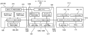
図12を参照すると、一実施形態による外科用ロボットシステムのコンピュータ部分のブロック図が示されている。外科用ロボットシステムは、コンピュータシステム110及び1つ以上のUID126を有するユーザコンソール120を含むことができる。コンピュータシステム110及びUID126は、特定の機能に適した回路を有し、したがって、図示された回路は、例として提供され、限定するものではない。 With reference to FIG. 12, a block diagram of the computer portion of the surgical robot system according to one embodiment is shown. The surgical robot system can include a computer system 110 and a user console 120 with one or more UID 126s. The computer system 110 and UID 126 have circuits suitable for a particular function, and therefore the circuits shown are provided by way of example and are not limited.

ユーザコンソール120は、外科用ロボットシステム100の一部、例えば、ロボットアーム112及び/又は外科用ツール104を制御することができる。UID126は、外科用ロボットシステム100を制御するための入力コマンドを提供するために、コンピュータシステム110及び/又は外科用ロボットシステム100に通信可能に連結されてもよい。例えば、UID126は、追跡センサ214からの信号に応答して、UIDプロセッサ520によって生成された空間状態信号、グリップリンク変位センサ518からの信号に応答して、UIDプロセッサ520によって生成されたグリップ信号、指クラッチ802の導電パッド904の静電容量の検出された変化に応答して、UIDプロセッサ520によって生成されたクラッチ信号、グリップクランク容量感知パッド804、806、808又は810の静電容量の検出された変化に応答して、UIDプロセッサ520によって生成されたインターロックオフ信号、といった電気制御信号1202を、コンピュータシステム110に通信することができる。電気信号は、外科用ロボットシステム100の動きを引き起こすか、又は外科用ロボットシステム100の動きを中断するための入力コマンドであってもよい。 The user console 120 can control a part of the surgical robot system 100, for example, the robot arm 112 and / or the surgical tool 104. The UID 126 may be communicatively coupled to the computer system 110 and / or the surgical robot system 100 to provide input commands for controlling the surgical robot system 100. For example, the UID 126 has a spatial state signal generated by the UID processor 520 in response to a signal from the tracking sensor 214, a grip signal generated by the UID processor 520 in response to a signal from the grip link displacement sensor 518. In response to the detected change in capacitance of the conductive pad 904 of the finger clutch 802, the capacitance of the clutch signal, grip crank capacitance sensing pad 804, 806, 808 or 810 generated by the UID processor 520 is detected. In response to the change, an electrical control signal 1202, such as an interlock-off signal generated by the UID processor 520, can be communicated to the computer system 110. The electrical signal may be an input command for inducing movement of the surgical robot system 100 or interrupting the movement of the surgical robot system 100.

入力電気信号は、有線又は無線接続を介して、UIDプロセッサ520によってコンピュータシステム110のコンソールプロセッサ1206に送信されてもよい。例えば、UID126は、電線1204を介して制御信号1202をコンソールプロセッサ1206に送信してもよい。あるいは、UID126は、無線通信リンクを介して制御信号1202をコンソールプロセッサ1206に送信してもよい。無線通信リンクは、コンピュータシステム110及びUID126のそれぞれのRF回路によって確立されてもよい。無線通信は、無線周波数信号、例えば、Wi−Fi短距離信号及び/又はブルートゥース(登録商標)などの好適な無線通信プロトコルを介して行うことができる。 The input electrical signal may be transmitted by the UID processor 520 to the console processor 1206 of the computer system 110 via a wired or wireless connection. For example, the UID 126 may transmit the control signal 1202 to the console processor 1206 via the electric wire 1204. Alternatively, the UID 126 may transmit the control signal 1202 to the console processor 1206 via a wireless communication link. The wireless communication link may be established by the respective RF circuits of the computer system 110 and the UID 126. Radio communication can be performed via radio frequency signals, such as Wi-Fi short range signals and / or suitable radio communication protocols such as Bluetooth®.

コンピュータシステム110のコンソールプロセッサ1206は、上述の異なる機能及び性能を実行するための命令を実行してもよい。ユーザコンソール120のコンソールプロセッサ(単数又は複数)1206によって実行される命令は、非一時的機械可読媒体を含み得るローカルメモリ1208から取得されてもよい。命令は、外科用ロボットシステム100の構成要素、例えば、ロボットアーム(単数又は複数)112又は外科用ツール(単数又は複数)104に動作可能に連結されたアクチュエータ114などの、装置ドライバを有するオペレーティングシステムプログラムの形態であってもよい。 The console processor 1206 of the computer system 110 may execute instructions to perform the different functions and performances described above. Instructions executed by the console processor (s) 1206 of the user console 120 may be obtained from local memory 1208, which may include non-temporary machine-readable media. The instruction is an operating system having a device driver, such as a component of the surgical robot system 100, eg, an actuator 114 operably coupled to a robot arm (s) 112 or a surgical tool (s) 104. It may be in the form of a program.

一実施形態では、コンソールプロセッサ1206は、ユーザコンソール120の構成要素を制御する。例えば、1つ以上の座席アクチュエータ1209は、コンソールプロセッサ1206からのコマンドを受信して、座席122の動きを制御することができる。座席アクチュエータ(単数又は複数)1209は、前方/後方、背もたれ傾斜、ヘッドレスト位置などの1つ以上の自由度で座席122を動かすことができる。コンソールプロセッサ1206はまた、ディスプレイ128上に提示するためのビデオデータを送信することができる。したがって、コンソールプロセッサ1206は、ユーザコンソール120の動作を制御することができる。座席アクチュエータ(単数又は複数)1209又はコンソールプロセッサ1206への入力コマンドは、フットペダル(単数又は複数)124若しくはキーボード又はジョイスティックなどの別のインターフェース装置1211を介して、ユーザによって入力することができる。 In one embodiment, the console processor 1206 controls the components of the user console 120. For example, one or more seat actuators 1209 can receive commands from the console processor 1206 to control the movement of the seat 122. The seat actuator (s) 1209 can move the seat 122 with one or more degrees of freedom, such as front / rear, backrest tilt, headrest position, and the like. Console processor 1206 can also transmit video data for presentation on display 128. Therefore, the console processor 1206 can control the operation of the user console 120. Input commands to the seat actuator (s) 1209 or console processor 1206 can be entered by the user via a foot pedal (s) 124 or another interface device 1211 such as a keyboard or joystick.

コンソールプロセッサ1206は、リンク1210を介して制御信号1202を外科用ロボットシステム100に出力することができる。制御信号1202は、外科用ロボットシステム100の動きを制御するために送信されてもよい。コンピュータシステム110は、有線又は無線リンクを介して外科用ロボットシステム100に通信可能に連結されて、制御信号1202を1つ以上の外科用ロボットシステムプロセッサ(単数又は複数)1212に出力することができる。例えば、少なくとも1つのプロセッサ1212は、管制塔130内に配置することができ、外科用ロボットプラットフォーム111又は1つ以上のディスプレイ1220などのシステム構成要素に通信可能に連結されてもよい。外科用ロボットシステム100のアクチュエータ114は、外科用システムプロセッサ1212から制御コマンドを受信して、UID126の動きに対応する動作を引き起こすか、又はユーザ107が指クラッチ802に触れるか又はUID126を落下させるときに外科用ロボットシステム100のインターロックをクラッチ及び/又は切断することによって、外科用ロボットシステム100の動きを中断させることができる。 The console processor 1206 can output the control signal 1202 to the surgical robot system 100 via the link 1210. The control signal 1202 may be transmitted to control the movement of the surgical robot system 100. The computer system 110 is communicably linked to the surgical robot system 100 via a wired or wireless link and can output control signals 1202 to one or more surgical robot system processors (s) 1212. .. For example, at least one processor 1212 may be located within control tower 130 and may be communicably linked to system components such as surgical robot platform 111 or one or more displays 1220. When the actuator 114 of the surgical robot system 100 receives a control command from the surgical system processor 1212 to trigger an action corresponding to the movement of the UID 126, or when the user 107 touches the finger clutch 802 or drops the UID 126. By clutching and / or disengaging the interlock of the surgical robot system 100, the movement of the surgical robot system 100 can be interrupted.

図13を参照すると、一実施形態による、開放構成で手持ちされているユーザインターフェース装置の斜視図が示されている。UID126は、グリップクランク216が完全に開位置にある状態でユーザの手に保持されている。UID126は、ユーザによる正確な指の操作を可能にする。すなわち、ユーザの手は、制御グリップを回転させる、転がす、又は捻ることができる。更に、グリップクランク216は、ユーザの手がグリップクランク216を軸206に向かって内側につまむ又は握ると、外科医に触覚フィードバックを提供することができる。したがって、UID126は、向上した器用さ及び動きの精度を提供する。 With reference to FIG. 13, a perspective view of a user interface device held in an open configuration according to one embodiment is shown. The UID 126 is held in the user's hand with the grip crank 216 in the fully open position. The UID 126 allows the user to operate the finger accurately. That is, the user's hand can rotate, roll, or twist the control grip. Further, the grip crank 216 can provide tactile feedback to the surgeon when the user's hand pinches or grips the grip crank 216 inward toward the axis 206. Therefore, the UID 126 provides improved dexterity and motion accuracy.

前述の明細書において、本発明は、その特定の例示的な実施形態を参照して説明されている。以下の特許請求の範囲に記載される本発明のより広範な趣旨及び範囲から逸脱することなく、様々な修正がなされ得ることが明らかであろう。したがって、本明細書及び図面は、限定的な意味ではなく、例示的な意味で考慮されるべきである。
In the aforementioned specification, the present invention is described with reference to its particular exemplary embodiment. It will be apparent that various modifications can be made without departing from the broader intent and scope of the invention described in the claims below. Therefore, the specification and drawings should be considered in an exemplary sense, not in a limiting sense.

Claims (20)

外科用ロボットシステム内のロボット外科用ツールを操作するためのユーザインターフェース装置であって、
中心軸の周りに本体表面を有する装置本体と、
複数のグリップリンクであって、各グリップリンクは、装置クランク継手において前記装置本体に枢動可能に連結されたグリップクランクを含み、前記グリップリンクは、前記ロボット外科用ツールのグリップ動作を操作するためのグリップ信号を生成するように構成されている、グリップリンクと、
前記装置本体内に取り付けられた追跡センサであって、前記装置本体の動きを追跡し、入力空間状態信号を生成して、前記ロボット外科用ツールの空間動作を制御するように構成されている、追跡センサと、を備える、ユーザインターフェース装置。
A user interface device for operating robotic surgical tools in a surgical robot system.
A device body that has a body surface around the central axis,
A plurality of grip links, each of which includes a grip crank pivotally connected to the device body at the device crank joint, the grip link for manipulating the grip movement of the robotic surgical tool. Grip links and, which are configured to generate grip signals for
A tracking sensor mounted within the body of the device, which is configured to track the movement of the body of the device, generate an input spatial state signal, and control the spatial movement of the robotic surgical tool. A user interface device, including a tracking sensor.
各グリップリンクは、従動クランク継手において前記グリップクランクに枢動可能に連結された従動アームを含み、前記従動アームは、従動スライダ継手においてスライダに枢動可能に連結され、前記スライダは、前記中心軸に沿って動くようにスライダ本体継手において前記装置本体の前記本体表面に摺動可能に連結されている、請求項1に記載のユーザインターフェース装置。 Each grip link includes a driven arm pivotally connected to the grip crank in the driven crank joint, the driven arm is pivotally connected to the slider in the driven slider joint, and the slider is the central axis. The user interface device according to claim 1, wherein the slider main body joint is slidably connected to the main body surface of the device main body so as to move along the same. 前記装置クランク継手、前記従動クランク継手、及び前記従動スライダ継手は回転継手であり、前記スライダ本体継手はプリズム継手である、請求項2に記載のユーザインターフェース装置。 The user interface device according to claim 2, wherein the device crank joint, the driven crank joint, and the driven slider joint are rotary joints, and the slider body joint is a prism joint. 前記グリップリンクはそれぞれの従動アームを有し、前記従動アームは同じスライダに連結されている、請求項3に記載のユーザインターフェース装置。 The user interface device according to claim 3, wherein the grip link has each driven arm, and the driven arm is connected to the same slider. 前記グリップリンクは、前記中心軸に沿って交差するそれぞれの平面に沿って前記装置本体から延在するグリップクランクを有するグリップリンクの第1のセットを含み、前記それぞれの平面は、前記中心軸を中心に等角である、請求項1に記載のユーザインターフェース装置。 The grip links include a first set of grip links having grip cranks extending from the device body along their respective planes intersecting the central axis, the respective planes having the central axis. The user interface device according to claim 1, which is equiangular at the center. グリップリンクの前記第1のセットの前記それぞれの平面の間で前記装置本体から延在する少なくとも1つのグリップクランクを有する、グリップリンクの第2のセットを更に備える、請求項5に記載のユーザインターフェース装置。 The user interface of claim 5, further comprising a second set of grip links having at least one grip crank extending from the device body between the respective planes of the first set of grip links. Device. 前記スライダを第1の端部に向かって又は前記第1の端部から離れるように動かすために、前記装置本体に連結された第1の端部と、前記スライダに連結された第2の端部と、を有するバイアス要素を更に備える、請求項2に記載のユーザインターフェース装置。 A first end connected to the device body and a second end connected to the slider to move the slider towards or away from the first end. The user interface device according to claim 2, further comprising a bias element having a portion. 前記バイアス要素は線形アクチュエータである、請求項7に記載のユーザインターフェース装置。 The user interface device according to claim 7, wherein the bias element is a linear actuator. 双安定ラッチ機構を更に備え、前記双安定ラッチ機構は、非ラッチ位置と、移動終了位置と、ラッチ位置との間でカムに沿って移動するカム従動子を含み、前記カム従動子は、前記グリップクランクが開位置と閉位置との間で前記装置本体に向かって枢動するとき、前記非ラッチ位置から前記移動終了位置へと動き、前記カム従動子は、前記グリップクランクが前記閉位置とロック位置との間で前記装置本体から離れるように枢動するとき、前記移動終了位置から前記ラッチ位置へと動く、請求項7に記載のユーザインターフェース装置。 The bistable latch mechanism further comprises a bistable latch mechanism that includes a cam slave that moves along the cam between a non-latch position, a movement end position, and a latch position. When the grip crank pivotally moves toward the device body between the open position and the closed position, it moves from the non-latch position to the movement end position, and the cam slave moves the grip crank to the closed position. The user interface device according to claim 7, wherein the user interface device moves from the movement end position to the latch position when the device is pivotally moved away from the main body of the device with respect to the lock position. 前記グリップクランクは、前記閉位置において前記ロック位置よりも前記中心軸に近く、前記グリップクランクは、前記ロック位置において前記開位置よりも前記中心軸に近い、請求項9に記載のユーザインターフェース装置。 The user interface device according to claim 9, wherein the grip crank is closer to the central axis than the lock position in the closed position, and the grip crank is closer to the central axis than the open position in the lock position. 前記グリップクランクに取り付けられたグリップクランク容量感知パッドと、
前記グリップクランク容量感知パッドの静電容量の変化を検出するために、前記グリップクランク容量感知パッドに電気的に結合されたユーザインターフェース装置プロセッサと、を更に備え、前記グリップクランク容量感知パッドの前記静電容量の前記変化を検出することに応答して、インターロックオフ信号を生成するように構成されている、請求項1に記載のユーザインターフェース装置。
The grip crank capacity sensing pad attached to the grip crank and
Further comprising a user interface device processor electrically coupled to the grip crank capacitance sensing pad to detect a change in capacitance of the grip crank capacitance sensing pad, said static of the grip crank capacitance sensing pad. The user interface device according to claim 1, wherein an interlock-off signal is generated in response to detecting the change in capacitance.
前記グリップクランクに取り付けられた第2のグリップクランク容量感知パッドを更に備え、前記ユーザインターフェース装置プロセッサは、前記グリップクランク容量感知パッド及び前記第2のグリップクランク容量感知パッドのそれぞれの静電容量における変化のシーケンスを検出するために、前記第2のグリップクランク容量感知パッドに電気的に結合されている、請求項11に記載のユーザインターフェース装置。 Further comprising a second grip crank capacitance sensing pad attached to the grip crank, the user interface device processor is a variation in the capacitance of the grip crank capacitance sensing pad and the second grip crank capacitance sensing pad, respectively. 11. The user interface device of claim 11, which is electrically coupled to the second grip crank capacitance sensing pad to detect the sequence of. 前記装置本体に取り付けられた指クラッチを更に備え、前記指クラッチは、前記中心軸の周りに延在する導電パッドを含み、前記ユーザインターフェース装置プロセッサは、前記導電パッドに電気的に結合されて、前記導電パッドの静電容量の変化を検出することに応答してクラッチ信号を生成する、請求項12に記載のユーザインターフェース装置。 Further comprising a finger clutch attached to the device body, the finger clutch includes a conductive pad extending around the central axis, the user interface device processor being electrically coupled to the conductive pad. The user interface device according to claim 12, wherein a clutch signal is generated in response to detecting a change in the capacitance of the conductive pad. 外科用ロボットシステムであって、
それぞれがロボットアームに取り付けられた1つ以上のロボット外科用ツールと、
1つ以上のユーザインターフェース装置であって、各ユーザインターフェース装置は、
中心軸の周りに本体表面を有する装置本体と、
複数のグリップリンクであって、各グリップリンクが、装置クランク継手において前記装置本体に枢動可能に連結されたグリップクランクを含む、グリップリンクと、
前記装置本体の動きを6つの自由度で追跡し、対応するロボット外科用ツールの空間動作を制御するための入力姿勢信号を生成するように構成された追跡センサと、
前記グリップリンクの動きに応答してグリップ信号を生成するように構成されたグリップリンク変位センサと、
前記1つ以上のユーザインターフェース装置及び前記1つ以上のロボット外科用ツールに通信可能に連結され、かつ、前記入力姿勢信号及び前記グリップ信号のうちの少なくとも1つに基づいて前記ロボット外科用ツールを制御するように構成された1つ以上のプロセッサと、を備える、外科用ロボットシステム。
Surgical robot system
One or more robotic surgical tools, each attached to a robot arm,
One or more user interface devices, each user interface device
A device body that has a body surface around the central axis,
A plurality of grip links, wherein each grip link includes a grip crank pivotally connected to the device body at the device crank joint.
A tracking sensor configured to track the movement of the device body with six degrees of freedom and generate an input posture signal to control the spatial movement of the corresponding robotic surgical tool.
A grip link displacement sensor configured to generate a grip signal in response to the movement of the grip link.
The robotic surgical tool is communicably linked to the one or more user interface devices and the one or more robotic surgical tools and is based on at least one of the input attitude signal and the grip signal. A surgical robot system comprising one or more processors configured to control.
前記グリップクランクに取り付けられたグリップクランク容量感知パッドと、
前記グリップクランク容量感知パッドの静電容量の変化を検出するために、前記グリップクランク容量感知パッドに電気的に結合されたユーザインターフェース装置プロセッサでと、を更に備え、前記ユーザインターフェース装置が、前記グリップクランク容量感知パッドの前記静電容量の前記変化を検出することに応答して、インターロックオフ信号を生成するように構成されている、請求項14に記載の外科用ロボットシステム。
The grip crank capacity sensing pad attached to the grip crank and
A user interface device processor electrically coupled to the grip crank capacitance sensing pad to detect a change in capacitance of the grip crank capacitance sensing pad. The surgical robot system according to claim 14, wherein an interlock-off signal is generated in response to detecting the change in the capacitance of the crank capacitance sensing pad.
前記装置本体に取り付けられた指クラッチを更に備え、前記指クラッチは、前記中心軸の周りに延在する導電パッドを含み、前記ユーザインターフェース装置プロセッサは、前記導電パッドに電気的に結合されて、前記導電パッドの静電容量の変化を検出することに応答してクラッチ信号を生成し、前記クラッチ信号は、前記入力姿勢信号の変化にかかわらず、前記外科用ロボットシステムの1つ以上のアクチュエータの動きを中断する、請求項15に記載の外科用ロボットシステム。 It further comprises a finger clutch attached to the device body, the finger clutch comprising a conductive pad extending around the central axis, the user interface device processor being electrically coupled to the conductive pad. A clutch signal is generated in response to detecting a change in the capacitance of the conductive pad, which is the clutch signal of one or more actuators of the surgical robot system regardless of the change in the input attitude signal. The surgical robot system according to claim 15, which interrupts movement. 前記1つ以上のユーザインターフェース装置は複数のユーザインターフェース装置であり、各ユーザインターフェース装置は、前記外科用ロボットシステムのそれぞれのアクチュエータに連結されたそれぞれのロボット外科用ツールのグリップ動作を制御するためのそれぞれのグリップ信号を生成する、請求項14に記載の外科用ロボットシステム。 The one or more user interface devices are a plurality of user interface devices, and each user interface device is for controlling the grip operation of each robot surgical tool connected to each actuator of the surgical robot system. The surgical robot system according to claim 14, which generates each grip signal. ユーザインターフェース装置を使用して外科用ロボットシステム内のロボット外科用ツールを操作するための方法であって、
6つの自由度の空間内での前記ユーザインターフェース装置の動きを追跡することと、
前記ロボット外科用ツールの空間動作を制御するための前記ユーザインターフェース装置の動きを表す入力姿勢信号を生成することと、
前記ユーザインターフェース装置の1つ以上のグリップリンクの動きを検出することと、
前記ロボット外科用ツールのグリップ動作を制御するためのグリップ信号を生成することと、を含む、方法。
A method for operating robotic surgical tools in a surgical robot system using a user interface device.
Tracking the movement of the user interface device in a space of six degrees of freedom and
To generate an input posture signal representing the movement of the user interface device for controlling the spatial movement of the robotic surgical tool, and
Detecting the movement of one or more grip links of the user interface device
A method comprising generating a grip signal for controlling the grip movement of the robotic surgical tool.
前記外科用ロボットシステムの1つ以上のプロセッサによって、前記ユーザインターフェース装置から前記入力姿勢信号又は前記グリップ信号のうちの1つ以上を受信することと、
前記入力姿勢信号又は前記グリップ信号のうちの少なくとも1つに基づいて、前記ロボット外科用ツールを作動させることと、を更に含む、請求項18に記載の方法。
Receiving one or more of the input attitude signals or the grip signals from the user interface device by one or more processors of the surgical robot system.
18. The method of claim 18, further comprising activating the robotic surgical tool based on at least one of the input attitude signal or the grip signal.
前記ユーザインターフェース装置のユーザインターフェース装置プロセッサによって、前記グリップクランクに取り付けられたグリップクランク容量感知パッドの静電容量の変化を検出することと、
前記グリップクランク容量感知パッドの前記静電容量の前記変化に応答して、前記ユーザインターフェース装置プロセッサによって、インターロックオフ信号を生成することと、を更に含む、請求項19に記載の方法。
The user interface device processor of the user interface device detects a change in the capacitance of the grip crank capacitance sensing pad attached to the grip crank, and
19. The method of claim 19, further comprising generating an interlock-off signal by the user interface device processor in response to the change in capacitance of the grip crank capacitance sensing pad.
JP2020568720A 2018-06-15 2018-06-15 User interface device with grip link Pending JP2021529014A (en)

Priority Applications (1)

Application Number Priority Date Filing Date Title
JP2023015211A JP7427815B2 (en) 2018-06-15 2023-02-03 User interface device with grip links

Applications Claiming Priority (1)

Application Number Priority Date Filing Date Title
PCT/US2018/037941 WO2019240824A1 (en) 2018-06-15 2018-06-15 User interface device having grip linkages

Related Child Applications (1)

Application Number Title Priority Date Filing Date
JP2023015211A Division JP7427815B2 (en) 2018-06-15 2023-02-03 User interface device with grip links

Publications (2)

Publication Number Publication Date
JP2021529014A true JP2021529014A (en) 2021-10-28
JPWO2019240824A5 JPWO2019240824A5 (en) 2022-05-23

Family

ID=62952393

Family Applications (2)

Application Number Title Priority Date Filing Date
JP2020568720A Pending JP2021529014A (en) 2018-06-15 2018-06-15 User interface device with grip link
JP2023015211A Active JP7427815B2 (en) 2018-06-15 2023-02-03 User interface device with grip links

Family Applications After (1)

Application Number Title Priority Date Filing Date
JP2023015211A Active JP7427815B2 (en) 2018-06-15 2023-02-03 User interface device with grip links

Country Status (3)

Country Link
EP (1) EP3787852B1 (en)
JP (2) JP2021529014A (en)
WO (1) WO2019240824A1 (en)

Families Citing this family (1)

* Cited by examiner, † Cited by third party
Publication number Priority date Publication date Assignee Title
US11207147B2 (en) * 2020-03-27 2021-12-28 Auris Health, Inc. Hand-manipulated input device for robotic system

Citations (6)

* Cited by examiner, † Cited by third party
Publication number Priority date Publication date Assignee Title
JP2013035117A (en) * 2011-08-04 2013-02-21 Olympus Corp Manipulation input device and manipulator system having the same
WO2016201544A1 (en) * 2015-06-16 2016-12-22 Titan Medical Inc. Hand grip apparatus for receiving operator input in a robotic surgery system
US20170095298A1 (en) * 2015-10-02 2017-04-06 Ethicon Endo-Surgery, Llc User input device for robotic surgical system
JP2017119168A (en) * 2009-11-13 2017-07-06 インテュイティブ サージカル オペレーションズ, インコーポレイテッド Patient-side surgeon interface for minimally invasive, teleoperated surgical instrument
JP2018513711A (en) * 2015-02-24 2018-05-31 エスアールアイ インターナショナルSRI International Very dexterous system user interface
WO2018107062A1 (en) * 2016-12-09 2018-06-14 Verb Surgical Inc. User interface devices for use in robotic surgery

Family Cites Families (3)

* Cited by examiner, † Cited by third party
Publication number Priority date Publication date Assignee Title
US8423182B2 (en) * 2009-03-09 2013-04-16 Intuitive Surgical Operations, Inc. Adaptable integrated energy control system for electrosurgical tools in robotic surgical systems
KR20130015440A (en) * 2011-08-03 2013-02-14 주식회사 이턴 Master gripper of surgical robot
JP6005950B2 (en) * 2011-08-04 2016-10-12 オリンパス株式会社 Surgery support apparatus and control method thereof

Patent Citations (6)

* Cited by examiner, † Cited by third party
Publication number Priority date Publication date Assignee Title
JP2017119168A (en) * 2009-11-13 2017-07-06 インテュイティブ サージカル オペレーションズ, インコーポレイテッド Patient-side surgeon interface for minimally invasive, teleoperated surgical instrument
JP2013035117A (en) * 2011-08-04 2013-02-21 Olympus Corp Manipulation input device and manipulator system having the same
JP2018513711A (en) * 2015-02-24 2018-05-31 エスアールアイ インターナショナルSRI International Very dexterous system user interface
WO2016201544A1 (en) * 2015-06-16 2016-12-22 Titan Medical Inc. Hand grip apparatus for receiving operator input in a robotic surgery system
US20170095298A1 (en) * 2015-10-02 2017-04-06 Ethicon Endo-Surgery, Llc User input device for robotic surgical system
WO2018107062A1 (en) * 2016-12-09 2018-06-14 Verb Surgical Inc. User interface devices for use in robotic surgery

Also Published As

Publication number Publication date
EP3787852A1 (en) 2021-03-10
EP3787852B1 (en) 2023-10-25
WO2019240824A1 (en) 2019-12-19
JP7427815B2 (en) 2024-02-05
EP3787852C0 (en) 2023-10-25
JP2023052889A (en) 2023-04-12

Similar Documents

Publication Publication Date Title
US11980435B2 (en) User interface device having grip linkages
US20230301738A1 (en) Master control device and methods therefor
US20230082915A1 (en) Surgical robot systems comprising robotic telemanipulators and integrated laparoscopy
US20220022988A1 (en) User interface device having finger clutch
US20200275985A1 (en) Master control device with multi-finger grip and methods therefor
EP3651677B1 (en) Systems and methods for switching control between multiple instrument arms
KR102549816B1 (en) System and method for safe operation of device
US20210330407A1 (en) Surgical robot systems comprising robotic telemanipulators and integrated laparoscopy
US11278361B2 (en) Sensors for touch-free control of surgical robotic systems
US11504200B2 (en) Wearable user interface device
JP2023052783A (en) User interface device having finger clutch
JP7427815B2 (en) User interface device with grip links
US11696807B2 (en) Drop detection of ungrounded master controller for a surgical robot
WO2023192465A1 (en) User interface interaction elements with associated degrees of freedom of motion

Legal Events

Date Code Title Description
A521 Request for written amendment filed

Free format text: JAPANESE INTERMEDIATE CODE: A523

Effective date: 20201210

A621 Written request for application examination

Free format text: JAPANESE INTERMEDIATE CODE: A621

Effective date: 20201210

A521 Request for written amendment filed

Free format text: JAPANESE INTERMEDIATE CODE: A821

Effective date: 20210415

RD02 Notification of acceptance of power of attorney

Free format text: JAPANESE INTERMEDIATE CODE: A7422

Effective date: 20210415

RD04 Notification of resignation of power of attorney

Free format text: JAPANESE INTERMEDIATE CODE: A7424

Effective date: 20210420

A131 Notification of reasons for refusal

Free format text: JAPANESE INTERMEDIATE CODE: A131

Effective date: 20220215

A524 Written submission of copy of amendment under article 19 pct

Free format text: JAPANESE INTERMEDIATE CODE: A524

Effective date: 20220512

A521 Request for written amendment filed

Free format text: JAPANESE INTERMEDIATE CODE: A523

Effective date: 20220513

A02 Decision of refusal

Free format text: JAPANESE INTERMEDIATE CODE: A02

Effective date: 20221004

A521 Request for written amendment filed

Free format text: JAPANESE INTERMEDIATE CODE: A523

Effective date: 20230203

C60 Trial request (containing other claim documents, opposition documents)

Free format text: JAPANESE INTERMEDIATE CODE: C60

Effective date: 20230203

C11 Written invitation by the commissioner to file amendments

Free format text: JAPANESE INTERMEDIATE CODE: C11

Effective date: 20230214

C609 Written withdrawal of request for trial/appeal

Free format text: JAPANESE INTERMEDIATE CODE: C609

Effective date: 20230216