JP2021525603A - Photoacoustic probe for endoscopes - Google Patents
Photoacoustic probe for endoscopes Download PDFInfo
- Publication number
- JP2021525603A JP2021525603A JP2020567161A JP2020567161A JP2021525603A JP 2021525603 A JP2021525603 A JP 2021525603A JP 2020567161 A JP2020567161 A JP 2020567161A JP 2020567161 A JP2020567161 A JP 2020567161A JP 2021525603 A JP2021525603 A JP 2021525603A
- Authority
- JP
- Japan
- Prior art keywords
- catheter
- photoacoustic
- tip
- ultrasonic
- ultrasonic probe
- Prior art date
- Legal status (The legal status is an assumption and is not a legal conclusion. Google has not performed a legal analysis and makes no representation as to the accuracy of the status listed.)
- Pending
Links
Images


Classifications
-
- A—HUMAN NECESSITIES
- A61—MEDICAL OR VETERINARY SCIENCE; HYGIENE
- A61B—DIAGNOSIS; SURGERY; IDENTIFICATION
- A61B5/00—Measuring for diagnostic purposes; Identification of persons
- A61B5/0093—Detecting, measuring or recording by applying one single type of energy and measuring its conversion into another type of energy
- A61B5/0095—Detecting, measuring or recording by applying one single type of energy and measuring its conversion into another type of energy by applying light and detecting acoustic waves, i.e. photoacoustic measurements
-
- A—HUMAN NECESSITIES
- A61—MEDICAL OR VETERINARY SCIENCE; HYGIENE
- A61B—DIAGNOSIS; SURGERY; IDENTIFICATION
- A61B5/00—Measuring for diagnostic purposes; Identification of persons
- A61B5/45—For evaluating or diagnosing the musculoskeletal system or teeth
- A61B5/4514—Cartilage
-
- A—HUMAN NECESSITIES
- A61—MEDICAL OR VETERINARY SCIENCE; HYGIENE
- A61B—DIAGNOSIS; SURGERY; IDENTIFICATION
- A61B5/00—Measuring for diagnostic purposes; Identification of persons
- A61B5/45—For evaluating or diagnosing the musculoskeletal system or teeth
- A61B5/4528—Joints
-
- A—HUMAN NECESSITIES
- A61—MEDICAL OR VETERINARY SCIENCE; HYGIENE
- A61B—DIAGNOSIS; SURGERY; IDENTIFICATION
- A61B5/00—Measuring for diagnostic purposes; Identification of persons
- A61B5/68—Arrangements of detecting, measuring or recording means, e.g. sensors, in relation to patient
- A61B5/6846—Arrangements of detecting, measuring or recording means, e.g. sensors, in relation to patient specially adapted to be brought in contact with an internal body part, i.e. invasive
- A61B5/6847—Arrangements of detecting, measuring or recording means, e.g. sensors, in relation to patient specially adapted to be brought in contact with an internal body part, i.e. invasive mounted on an invasive device
- A61B5/6852—Catheters
-
- A—HUMAN NECESSITIES
- A61—MEDICAL OR VETERINARY SCIENCE; HYGIENE
- A61B—DIAGNOSIS; SURGERY; IDENTIFICATION
- A61B2505/00—Evaluating, monitoring or diagnosing in the context of a particular type of medical care
- A61B2505/05—Surgical care
-
- A—HUMAN NECESSITIES
- A61—MEDICAL OR VETERINARY SCIENCE; HYGIENE
- A61B—DIAGNOSIS; SURGERY; IDENTIFICATION
- A61B2562/00—Details of sensors; Constructional details of sensor housings or probes; Accessories for sensors
- A61B2562/22—Arrangements of medical sensors with cables or leads; Connectors or couplings specifically adapted for medical sensors
- A61B2562/225—Connectors or couplings
- A61B2562/227—Sensors with electrical connectors
-
- A—HUMAN NECESSITIES
- A61—MEDICAL OR VETERINARY SCIENCE; HYGIENE
- A61B—DIAGNOSIS; SURGERY; IDENTIFICATION
- A61B8/00—Diagnosis using ultrasonic, sonic or infrasonic waves
- A61B8/12—Diagnosis using ultrasonic, sonic or infrasonic waves in body cavities or body tracts, e.g. by using catheters
Landscapes
- Health & Medical Sciences (AREA)
- Life Sciences & Earth Sciences (AREA)
- Physics & Mathematics (AREA)
- Molecular Biology (AREA)
- Animal Behavior & Ethology (AREA)
- Pathology (AREA)
- Engineering & Computer Science (AREA)
- Biomedical Technology (AREA)
- Heart & Thoracic Surgery (AREA)
- Medical Informatics (AREA)
- Veterinary Medicine (AREA)
- Surgery (AREA)
- Biophysics (AREA)
- General Health & Medical Sciences (AREA)
- Public Health (AREA)
- Dentistry (AREA)
- Oral & Maxillofacial Surgery (AREA)
- Orthopedic Medicine & Surgery (AREA)
- Rheumatology (AREA)
- Acoustics & Sound (AREA)
- Ultra Sonic Daignosis Equipment (AREA)
Abstract
本発明は、カテーテル(4)と、前記カテーテルの先端(40)に設けられる超音波センサ(5)と、レーザー光源に接続するのに適し、前記カテーテル内に前記先端(40)まで延在する少なくとも1つの光ファイバ(50)と、を備え、前記カテーテルは、傾斜した先端部(42)および/または傾斜した先端(40)を有することを特徴とする、光音響超音波プローブ(100)に関する。【選択図】 図1The present invention is suitable for connecting to a catheter (4), an ultrasonic sensor (5) provided at the tip (40) of the catheter, and a laser light source, and extends into the catheter to the tip (40). With respect to a photoacoustic ultrasonic probe (100) comprising at least one optical fiber (50), said catheter having a sloping tip (42) and / or a sloping tip (40). .. [Selection diagram] Fig. 1
Description
本発明は、内視鏡用光音響プローブに関する。 The present invention relates to a photoacoustic probe for an endoscope.
医用イメージングは、磁気共鳴、超音波の反射、放射線、X線の吸収など、さまざまな物理現象から画像を取得およびレンダリングする手段を含んでいる。これらの技術により、人体の生理機能や代謝を観察し、正確な診断を確立し、治療法の選択を導くことができる。しかしながら、一部の情報にアクセスできない、ユーザーフレンドリーでない(特にリアルタイムではない)、照射が患者や医療スタッフにとって大きな問題として認識されているなど、これらのイメージング法は不十分である。 Medical imaging includes means for acquiring and rendering images from a variety of physical phenomena such as magnetic resonance, ultrasonic reflection, radiation, and X-ray absorption. With these techniques, it is possible to observe the physiological function and metabolism of the human body, establish an accurate diagnosis, and guide the selection of treatment method. However, these imaging methods are inadequate, such as inaccessibility of some information, non-user-friendly (not particularly real-time), and irradiation being perceived as a major problem for patients and medical staff.
手術の種類に応じて、特定の技術のみが手術室で利用できる。整形外科では骨の構造を特定する必要があるため、主にX線が使用される。 Depending on the type of surgery, only certain techniques are available in the operating room. X-rays are mainly used in orthopedics because it is necessary to identify the structure of the bone.
術中画像の使用は、損傷した組織に関する追加情報を提供すること、手術法の精度を高めること、低侵襲手術における処置時間を短縮することを目的としており、これにより臨床的利益を高めることができる。 The use of intraoperative images is aimed at providing additional information about damaged tissue, improving the accuracy of surgical procedures, and reducing treatment time in minimally invasive surgery, which can increase clinical benefit. ..
関節鏡検査は、点状切開を介して関節に小型カメラを導入し、第2の点状開口を介して小型器具を導入する低侵襲の外科的処置である。これにより、外科医は、関節腔の解剖学的構造を評価しながら診断を行い、適切な器具により適切な治療を行うことができる。外来で行われるこの外科的アプローチは、非切開手術を可能にし、術後の罹患率を低下させる(入院時間と機能回復期間の短縮)ことにより、外科診療に革命をもたらした。 Arthroscopy is a minimally invasive surgical procedure that introduces a small camera into a joint through a punctate incision and a small instrument through a second punctate opening. This allows the surgeon to make a diagnosis while assessing the anatomy of the joint cavity and to provide appropriate treatment with the appropriate instrument. This outpatient surgical approach has revolutionized surgical practice by enabling non-incisional surgery and reducing postoperative morbidity (shortening hospital stays and recovery times).
膝と肩の関節は、この外科的革新の恩恵をすぐに受けた。これらの関節を構成する解剖学的構造の全部または一部は、外傷または変形性関節症で変化する可能性がある。したがって、膝の関節鏡検査は、半月板(例えば、切除)、軟骨(例えば、安定化)、滑膜(例えば、癒着切除)、小さな軟骨片または骨片(異物)の切除、または膝のより大きな手術(靭帯形成術など)に関連し得る。同様に、非網羅的であるが、肩の関節鏡検査の適応は、回転子カフの石灰性腱障害や、関節鏡検査下で滑液包切除や肩甲骨形成術を実施することによって治療される肩峰下衝突のケア、あるいは、術中に回転子カフの断裂を認定するために提起される。 The knee and shoulder joints immediately benefited from this surgical innovation. All or part of the anatomical structures that make up these joints can change with trauma or osteoarthritis. Therefore, knee arthroscopy can be performed by removing the meniscus (eg, excision), cartilage (eg, stabilizing), synovium (eg, adhesionctomy), small cartilage or bone fragments (foreign body), or twisting the knee. It can be associated with major surgery (such as ligamentoplasty). Similarly, although non-exhaustive, shoulder arthroscopy indications are treated by calcifying tendonopathy of the rotator cuff and by performing bursectomy and acromionoplasty under arthroscopy. It is raised to care for subacromial collisions or to identify rupture of the rotator cuff during surgery.
関節鏡検査時、関節腔の内側の視覚的探索は、関節を構成する構造の表面に限定されるため、潜在的な診断または治療に制限が生じる。さらに、アクセスできない領域があるため、解剖学的構造の血管新生を示すための造影剤または蛍光剤の注入には適していない。 During arthroscopy, the visual exploration of the inside of the joint cavity is limited to the surface of the structures that make up the joint, limiting potential diagnosis or treatment. In addition, some areas are inaccessible and are not suitable for injection of contrast or fluorescent agents to indicate angiogenesis of the anatomical structure.
内視鏡用光音響プローブは、解剖学的構造を詳細にイメージングするだけでなく、この構造の血管新生をイメージングすることも可能であり、外科医に追加情報を提供する。 The endoscopic photoacoustic probe can not only image the anatomical structure in detail, but also the angiogenesis of this structure, providing additional information to the surgeon.
しかしながら、関節の構成やこのようなプローブの挿入に利用可能なスペースのため、関節鏡検査における光音響の使用は困難である。 However, the use of photoacoustic in arthroscopy is difficult due to the joint configuration and the space available for insertion of such probes.
本発明の目的は、関節鏡検査に適した内視鏡用光音響プローブを考案することである。 An object of the present invention is to devise an endoscopic photoacoustic probe suitable for arthroscopy.
この目的のため、本発明は、
カテーテルと、
カテーテルの先端に設けられる超音波センサと、
レーザー光源に接続するのに適し、カテーテル内に先端まで延在する少なくとも1つの光ファイバと、を備え、
カテーテルは、傾斜した先端部および/または傾斜した先端を有することを特徴とする光音響超音波プローブを提供する。
To this end, the present invention
With a catheter
An ultrasonic sensor installed at the tip of the catheter and
Suitable for connecting to a laser light source, with at least one optical fiber extending into the catheter to the tip,
The catheter provides a photoacoustic ultrasonic probe characterized by having a sloping tip and / or a sloping tip.
本明細書では、「基端」はプローブを取り扱う操作者の側のプローブの部分であり、「先端」はプローブが挿入される患者の体側のプローブの部分であると理解される。 As used herein, it is understood that the "base" is the portion of the probe on the side of the operator handling the probe and the "tip" is the portion of the probe on the side of the patient's body into which the probe is inserted.
一実施形態では、カテーテルは、カテーテルの基端部に対して10〜30°の角度で傾斜した先端部を有する。 In one embodiment, the catheter has a tip that is tilted at an angle of 10-30 ° with respect to the proximal end of the catheter.
一実施形態では、上記先端は、カテーテルの先端部の回転軸に対して10〜30°の角度で傾斜する。 In one embodiment, the tip is tilted at an angle of 10-30 ° with respect to the axis of rotation of the tip of the catheter.
特に有利には、カテーテルの先端は、カテーテルの基端部に対して30°傾斜した面内に延在する。 Particularly advantageous, the tip of the catheter extends in-plane at an angle of 30 ° with respect to the proximal end of the catheter.
好ましい実施形態では、プローブは、超音波センサの一方側に設けられる複数の光ファイバを備える。 In a preferred embodiment, the probe comprises a plurality of optical fibers provided on one side of an ultrasonic sensor.
一実施形態では、プローブは、
カテーテルの基端部に取り付けられる制御ハンドルと、
超音波ステーションに接続するのに適したコネクタと、
コネクタおよび制御ハンドルの間に延在する電気接続ケーブルと、
カテーテルを覆い、超音波およびレーザービームを通過させるのに適した材料からなる第1の部分と、制御ハンドルおよび電気接続ケーブルをコネクタまで覆う第2の部分と、第1の部分および第2の部分の間に配置され、制御ハンドルに着脱可能に取り付けられる取り付け具とを含むシースと、をさらに備える。
In one embodiment, the probe
A control handle attached to the base of the catheter,
With a connector suitable for connecting to an ultrasonic station,
An electrical connection cable that extends between the connector and the control handle,
A first part made of a material suitable for covering the catheter and passing ultrasonic and laser beams, a second part covering the control handle and the electrical connection cable to the connector, the first part and the second part. It further comprises a sheath, including an attachment that is disposed between and detachably attached to the control handle.
好ましい実施形態では、第1の部分は、ポリアミド−ポリエーテルブロック共重合体からなる。 In a preferred embodiment, the first portion consists of a polyamide-polyester block copolymer.
有利には、第1の部分の厚さは一定である。 Advantageously, the thickness of the first portion is constant.
一実施形態では、第1の部分の厚さは、0.4〜0.6mmである。 In one embodiment, the thickness of the first portion is 0.4-0.6 mm.
好ましくは、第2の部分の直径は、第1の部分より大きい。 Preferably, the diameter of the second portion is larger than that of the first portion.
有利には、取り付け具は、カテーテルを通すための中央開口部を有し、第1の部分は、取り付け具の中央開口部の周りに取り付けられ、第2の部分は、取り付け具の外周部に取り付けられる。 Advantageously, the fitting has a central opening for the catheter to pass through, a first portion mounted around the central opening of the fitting and a second portion on the outer periphery of the fitting. It is attached.
本発明の他の目的は、レーザー源を含む超音波ステーションと、超音波ステーションに接続された上述の光音響超音波プローブとを備え、超音波ステーションは、光音響超音波プローブによって取得された対象の関節内領域の血管新生の画像を表示するように構成されたプロセッサを含む、イメージングシステムに関する。 Another object of the present invention includes an ultrasonic station including a laser source and the above-mentioned photoacoustic ultrasonic probe connected to the ultrasonic station, wherein the ultrasonic station is an object acquired by the photoacoustic ultrasonic probe. With respect to an imaging system, including a processor configured to display an image of angiogenesis in the intra-articular region of the.
特に有利には、プロセッサは、半月板の超音波画像と、半月板の血管新生の光音響画像とを重ね合わせるように構成される。 Particularly advantageous, the processor is configured to superimpose an ultrasound image of the meniscus with a photoacoustic image of angiogenesis of the meniscus.
本発明の他の特徴および利点は、以下の添付の図面を参照して、以下の詳細な説明から明らかになるであろう。 Other features and advantages of the present invention will become apparent from the following detailed description with reference to the accompanying drawings below.
図面中、同一の参照記号は、同一の要素または同一の機能を有する要素を示す。 In the drawings, the same reference symbol indicates an element having the same element or the same function.
内視鏡用光音響プローブは、プローブが接続される超音波ステーションを含むイメージングシステムの一部を形成する。 The endoscopic photoacoustic probe forms part of an imaging system that includes an ultrasonic station to which the probe is connected.
ステーションは、超音波制御電子機器、レーザー光源、プローブによって取得された画像を処理するのに適したプロセッサ、表示画面、およびデータの入力と画像への注釈付けを可能にするキーボードで構成される。 The station consists of an ultrasonic controlled electronic device, a laser light source, a processor suitable for processing the image acquired by the probe, a display screen, and a keyboard that allows data input and annotation of the image.
肩または膝の関節鏡検査下での手術中、内視鏡用光音響プローブは、器具経路から関節に挿入される。プローブは、他の経路を用いる関節鏡と共に使用される。外科医は、関節鏡を利用してプローブの先端部を対象の領域に移動させ、プローブをその領域の解剖学的構造に向けることで検査を行う。 During surgery under arthroscopy of the shoulder or knee, an endoscopic photoacoustic probe is inserted into the joint through the instrumental pathway. The probe is used with an arthroscope that uses other pathways. The surgeon uses an arthroscope to move the tip of the probe to the area of interest and points the probe at the anatomy of that area for examination.
光音響プローブは、関節での超音波画像の撮影を可能にする超音波センサと、超音波画像と組み合わせられる光音響画像を取得するためのレーザー光源に接続された1つまたは複数の光ファイバの両方を備える。実際、ヘモグロビンを含む解剖学的構造のレーザービームによる励起によって超音波が生じ、この超音波が超音波センサによって記録され、光音響画像が得られる。さらに、超音波センサは超音波を放出し、解剖学的構造によって反射された超音波を収集することで超音波画像が得られる。光音響画像は、超音波画像に重ね合わせることができる。 A photoacoustic probe is an optical fiber connected to an ultrasonic sensor that allows an ultrasonic image to be taken at a joint and a laser source for acquiring a photoacoustic image that is combined with the ultrasonic image. It has both. In fact, excitation by a laser beam of an anatomical structure containing hemoglobin produces ultrasonic waves, which are recorded by an ultrasonic sensor to obtain a photoacoustic image. In addition, ultrasonic sensors emit ultrasonic waves and collect the ultrasonic waves reflected by the anatomical structure to obtain ultrasonic images. The photoacoustic image can be superimposed on the ultrasonic image.
超音波の周波数は、有利には、5〜60Mhzの範囲である。 The frequency of the ultrasonic waves is advantageously in the range of 5-60 Mhz.
レーザービームの波長は、有利には、500〜1200nmである。 The wavelength of the laser beam is advantageously 500-1200 nm.
図1〜図3は、本発明のプローブのカテーテルを示す図である。 1 to 3 are views showing the catheter of the probe of the present invention.
カテーテル4は、超音波センサ5と、カテーテルに沿って先端40まで延在する少なくとも1つの光ファイバ50とを備える。カテーテルの先端は、光ファイバに面するレンズを備える。
The
好ましくは、カテーテルは、励起光信号を増加させるために、複数の光ファイバ、例えば、6〜12本の光ファイバを含む。 Preferably, the catheter comprises a plurality of optical fibers, eg, 6-12 optical fibers, to increase the excitation light signal.
超音波センサは、有利には、線形アレイ状に配置された、例えば15〜25個の素子を含む多素子トランスデューサを含む。 Ultrasonic sensors preferably include multi-element transducers arranged in a linear array, including, for example, 15 to 25 elements.
有利には、超音波センサ5は、カテーテルの先端40に配置される。光ファイバ50は、好ましくは、超音波センサの一方側に配置される。
Advantageously, the
カテーテルは、一般に、10〜20cmの長さと、数ミリメートル、例えば4mmの直径を有する。カテーテルは、例えばステンレス鋼やチタンで構成される。 Catheter generally has a length of 10 to 20 cm and a diameter of a few millimeters, for example 4 mm. The catheter is made of, for example, stainless steel or titanium.
カテーテルは、傾斜した先端部42および/または傾斜した先端40を有する。「傾斜した先端部」とは、カテーテルの先端部42がカテーテルの基端部41に対して傾斜していることを意味すると解釈される(図2の角度α)。直線状の先端部および基端部は、湾曲部43によって接続される。「傾斜した先端」とは、先端40の平面が、カテーテルの先端部42の回転軸に対して傾斜していることを意味すると解釈される(図2の角度β)。傾斜角α、βは、通常、約10度〜約30度のオーダーであり、組み合わせることができる。
The catheter has a sloping
したがって、基端部に対してカテーテルの先端の傾斜が30°であるカテーテルであれば、検査する関節の形状により良好に適応することができ、関節鏡検査において特に有利である。例えば、カテーテルは、カテーテルの基端部に対して10°傾斜した先端部と、カテーテルの回転軸に対して20°の角度で傾斜した先端を有し得る。 Therefore, a catheter having an inclination of the tip of the catheter at 30 ° with respect to the proximal end can be better adapted to the shape of the joint to be examined, which is particularly advantageous in arthroscopy. For example, a catheter can have a tip that is tilted 10 ° with respect to the proximal end of the catheter and a tip that is tilted at an angle of 20 ° with respect to the axis of rotation of the catheter.
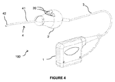
図4はプローブの概略図である。 FIG. 4 is a schematic view of the probe.
プローブ100は、超音波ステーション(不図示)に接続されるコネクタ1を備える。
The
コネクタ1は、電気接続ケーブル3を介して制御ハンドル2に接続される。制御ハンドルは、処置中にユーザが手に持つ部材である。ハンドルは、例えば、静画または動画の取得を閲覧または検証するためにユーザが押すことができる1つまたは複数のボタン20を備える。
The
カテーテル4の基端部41は、ハンドル2に取り付けられる。
The
有利な実施形態では、プローブは、カテーテルの先端から超音波ステーションに接続するコネクタまでプローブを完全に覆う滅菌シースによって保護される。シースは一体型であり、コネクタの位置にのみ開口を有する。 In an advantageous embodiment, the probe is protected by a sterile sheath that completely covers the probe from the tip of the catheter to the connector that connects to the ultrasound station. The sheath is integrated and has an opening only at the position of the connector.
図5はこのようなシースを備えた内視鏡用光音響プローブを示す図であり、図6はシースのみを示す。 FIG. 5 is a diagram showing an endoscopic photoacoustic probe provided with such a sheath, and FIG. 6 shows only the sheath.
シース10は、カテーテルを覆うのに適した第1の部分10aと、ハンドルおよび接続ケーブルを覆う、幅の広い第2の部分10bとを有する。シースの寸法は、プローブの形状や寸法に適合するように選択される。通常、第1および第2の部分はそれぞれ、円形断面の円筒形を有する。
The
第1の部分10aは、カテーテルの嵩を過度に増加させないようにカテーテル4の形状を可能な限り密接に包み、シースがカテーテル上を滑りやすいようにわずかな間隙が設けられる。例えば、厚さ0.5mmのシースと直径4mmのカテーテルの場合、第1の部分の外径は5.4mmのオーダーである。シースの第1の部分10aは、レンズに面することを含め、その先端で閉じられる。第1の部分10aは、必要に応じてカテーテルの形状および曲率に適合するために、その材料および厚さにより十分な柔軟性を有する。
The
シースの第1および第2の部分は、取り付け具11によって接続され、これにより、シースがプローブのハンドルに着脱可能に取り付けられる。 The first and second portions of the sheath are connected by a fitting 11, which allows the sheath to be detachably attached to the handle of the probe.
取り付け具は、通常、熱可塑性材料からなる。 The fixture is usually made of a thermoplastic material.
シースの第1の部分10aは、十分な解像度でイメージングを実行できるように、レーザービームおよび超音波信号を十分に低い減衰で通過させるのに適した材料で構成される。以下でこの機能に適した材料の選択について詳細に説明する。好ましくは、シースの第1の部分は、PEBAXTMという名称で販売されているポリアミド−ポリエーテルブロック共重合体で構成される。特に、PEBAXTM2533が好ましく、これには劣るがPEBAXTM3533も十分使用できる。シースの第1の部分の厚さは、超音波の大きな減衰を引き起こさないよう、十分に薄く選択される。第1の部分の厚さは、例えば0.4〜0.6mm、好ましくは0.5mmである。この厚さは、有利には、第1の部分の全長にわたって一定である。
The
シースの第2の部分10bは、第1の部分と同じ材料から構成されてもよく、別の材料で構成されてもよい。第2の部分は、超音波を通過させることを意図していない。第2の部分は、必ずしもコネクタへの取り付け手段を含まなくてもよい。実際には、接続ケーブルの周りに配置するだけで、手術部位の非滅菌領域までプローブを覆うのに十分な長さである。
The
取り付け具11は、カテーテル4を通すための中央開口部を有し、その周りに半径方向に延在する。シースの第1の部分10aは、この開口部110の周りの、取り付け具の中央部分に取り付けられ、取り付け具の先端側から延びる。シースの第2の部分10bは、取り付け具の外周部に取り付けられ、取り付け具の基端側から延びる。第1および第2の部分10a、10bは、任意の適切な手段によって、例えば、取り付け具に接着することによって、または取り付け具のオーバーモールドによって、密封して取り付け具11に取り付けられる。
The fitting 11 has a central opening through which the
取り付け具11およびハンドル2は、有利には、相互に可逆な締結手段を有する。一実施形態では、これらの締結は、クォーターターン機構によって行われる。別の方法では、これらの締結は、スナップ取り付け具によって行われる。
The fitting 11 and the
シースと取り付け具の2つの部分を形成する材料は、放射線によって劣化することなく滅菌することができる。好ましくは、滅菌は、エチレンオキシドへの曝露とそれに続くγ線への曝露によって実施される。 The material that forms the two parts of the sheath and the fixture can be sterilized without being degraded by radiation. Preferably, sterilization is carried out by exposure to ethylene oxide followed by exposure to gamma rays.
シース10は、プローブの残りの部分から取り外し可能であり、手術野に位置するプローブの部分を完全に覆うので、単独で滅菌することができ、プローブの機能要素に損傷を与えるリスクを冒さずに、滅菌された内視鏡用光音響装置を提供することを可能にする。通常、シースは、無菌性を維持するのに適したパッケージに封入される前に滅菌され、このパッケージから取り出されてプローブに配置される。
The
次に、シースの第1の部分の材料を選択するためのモダリティについて説明する。 Next, the modality for selecting the material of the first part of the sheath will be described.
本発明者らは、超音波を透過する様々な材料を試験し、それらを定性的および定量的に評価して、超音波信号を十分に低い減衰で通過させる能力について検証した。シースの材料の問題が主に超音波信号に対して提起される限り、レーザー励起は実施せずに超音波プローブについてシースを試験した。 We tested a variety of materials that transmit ultrasonic waves and evaluated them qualitatively and quantitatively to verify their ability to pass ultrasonic signals with sufficiently low attenuation. Sheaths were tested on ultrasonic probes without laser excitation, as long as sheath material issues were raised primarily for ultrasonic signals.
図10は、定性試験のための第1の構成の概略図である。 FIG. 10 is a schematic diagram of the first configuration for a qualitative test.
プローブの超音波センサ5は、PVC製の壁6に面して配置し、アセンブリは水に浸した。
The probe's
シースなしで第1の超音波画像を取得し、試験する各材料から構成されるシース10aをカテーテル4上に配置し、それぞれの超音波画像を取得した。
A first ultrasound image was acquired without a sheath, a
図11A〜図11Dに示される結果は、それぞれ、シースなし、PEBDからなるシース、PEBAXTM2533(好ましい材料)からなるシース、およびPEBAXTM3533からなるシースを用いて得られた。I1、I2、I3、I4で示される白い線は、それぞれレンズとシースの界面、シースと水の界面、水とPVC(プローブに面する壁の表面)の界面、およびPVC(プローブと反対側の壁の表面)と水の界面に対応する。シースがない図11Aでは、レンズと水の界面はI’1で示される。 The results shown in FIGS. 11A-11D were obtained with no sheath, a sheath made of PEBD, a sheath made of PEBAX TM 2533 (a preferred material), and a sheath made of PEBAX TM 3533, respectively. The white lines indicated by I1, I2, I3, and I4 are the lens-sheath interface, the sheath-water interface, the water-PVC (the surface of the wall facing the probe) interface, and the PVC (opposite the probe). Corresponds to the interface between the wall surface) and water. In FIG. 11A without a sheath, the interface between the lens and water is indicated by I'1.
シースに想定される材料としての第1の基準は、これらの境界の視認性である。シースなしで得られる視認性に可能な限り近い視認性を得ることが求められる。PVC壁の界面61、62の視認性の喪失は、シースでの超音波の吸収やシースの内面101および外面102によって反射されるエネルギーによって生じる。
The first criterion as an assumed material for the sheath is the visibility of these boundaries. It is required to obtain visibility as close as possible to the visibility obtained without a sheath. The loss of visibility at the
さらに、Eで示される線は、シースの厚さの空洞現象によるノイズ界面に対応する。この現象は、シースと水の間の音響インピーダンスの差によって引き起こされる。これにより、超音波はシースの外面とプローブの間を複数回往復し、往復するたびにエコーが生成され、画像上で水平線にとして変換される。このようなノイズ界面は、画像の品質に悪影響を及ぼす。これらのノイズエコーは、対象となる関節内の適用では、プローブが超音波診断される組織に非常に近いか、あるいは接触している必要があることを考えると、さらに問題となる。これは、潜在的なノイズエコーが解剖学的構造に重ね合わされて観察されることを示唆する。 Further, the line indicated by E corresponds to the noise interface due to the cavity phenomenon of the sheath thickness. This phenomenon is caused by the difference in acoustic impedance between the sheath and water. As a result, the ultrasonic wave reciprocates between the outer surface of the sheath and the probe a plurality of times, and each reciprocation generates an echo, which is converted into a horizontal line on the image. Such a noise interface adversely affects the quality of the image. These noise echoes are even more problematic given that the probe must be very close to or in contact with the tissue being ultrasound-diagnosed for intra-articular application. This suggests that potential noise echoes are observed superimposed on the anatomy.
したがって、ノイズエコーの存在と数が、材料についての第2の基準となる。このようなエコーは回避するか、少なくとも最小限に抑える必要がある。 Therefore, the presence and number of noise echoes are the second criterion for the material. Such echoes should be avoided, or at least minimized.
これらの画像では、予想される界面の視認性が良好であっても、PEBDからなるシースはノイズエコーを生成することが観察される。最も高性能な材料であるPEBAXTM253からなるシースは、良好な視認性を確保しつつ、ノイズエコーを生成しない。PEBAXTM3533も比較的適切な材料である。 In these images, it is observed that the sheath made of PEBD produces noise echoes, even though the expected interface visibility is good. The sheath made of PEBAX TM 253, which is the highest performance material, does not generate noise echo while ensuring good visibility. PEBAX TM 3533 is also a relatively suitable material.
以下の表は、ノイズエコーの数と界面の視認性の観点から、試験された材料とその分類を要約したものである。 The table below summarizes the materials tested and their classification in terms of the number of noise echoes and the visibility of the interface.

また、シースに想定されるさまざまな材料によって引き起こされる減衰を定量的に評価するため、別の調査を実施した。 Another study was conducted to quantitatively evaluate the damping caused by the various materials expected in the sheath.
図12は、定性試験のための第2の構成の概略図である。 FIG. 12 is a schematic diagram of a second configuration for a qualitative test.
プローブの超音波センサ5は、超音波を良好に反射する金属製の壁7に面して配置し、アセンブリは、プローブと金属壁との間に一定の距離を維持するため、ベンチによって取り付けた。
The probe's
シースなしで第1の超音波画像を取得し、試験する各材料から構成されるシース10aをカテーテル4上に配置し、それぞれの超音波画像を取得した。その後、減衰計算を行った。
A first ultrasound image was acquired without a sheath, a
図13は、試験されたさまざまな材料の全体的な減衰(すなわち、10〜15MHzの対象の周波数範囲全体に関する積分値)(dB)を表すグラフである。 FIG. 13 is a graph showing the overall attenuation (ie, integral value over the entire frequency range of 10-15 MHz of interest) (dB) of the various materials tested.
シリコーンとPEBAXTM4533は強い吸収を示すため、ノイズエコーを生成しないが好ましくないことが観察される。吸収率が約13dBであるPEBAXTM2533が最適な候補であり、次にPEBAXTM3533(15dB)とPEBD(15.5dB)が続く。しかしながら、PEBDは、ノイズエコーを生成するため、保持されない。 Silicone and PEBAX TM 4533 show strong absorption and therefore do not produce noise echoes, but are observed to be undesirable. PEBAX TM 2533, which has an absorption rate of about 13 dB, is the best candidate, followed by PEBAX TM 3533 (15 dB) and PEBD (15.5 dB). However, PEBD is not retained because it produces noise echoes.
結論として、PEBAXTM2533は、試験された中で減衰が最小の材料である。なお、試験されたPEBAXTMからなるシースは、他のシース(約0.8mm)よりも厚い(約2mmの厚さ)ことに留意されたい。したがって、同じ厚さの条件では、PEBAXTM2533からなるシースの減衰は、他のシースよりさらに小さくなる。 In conclusion, PEBAX TM 2533 is the material with the least attenuation tested. It should be noted that the sheath made of PEBAX TM tested is thicker (about 2 mm thick) than the other sheaths (about 0.8 mm). Therefore, under the same thickness condition, the damping of the sheath made of PEBAX TM 2533 is even smaller than that of the other sheaths.
PEBAXTM2533が実際に期待に沿うことを検証するため、動物の解剖学的部分にプローブを固定して軟骨画像を撮影した。すべての画像は、パラメータを同じに調整して撮影された。厚い(約2.6mm)軟骨(図14A、14Bを参照)と薄い(約1.6mm)軟骨(図15A、15Bを参照)の画像を記録した(図の下部に表示)。PEBAXTM2533で作られたシースでは、軟骨を区切る界面が依然として視認できる。 To verify that PEBAX TM 2533 actually met expectations, cartilage images were taken with the probe fixed to the anatomical part of the animal. All images were taken with the same parameters adjusted. Images of thick (about 2.6 mm) cartilage (see FIGS. 14A, 14B) and thin (about 1.6 mm) cartilage (see FIGS. 15A, 15B) were recorded (shown at the bottom of the figure). In the sheath made of PEBAX TM 2533, the interface separating the cartilage is still visible.
プローブが水中で裸の場合、界面は非常に眩しく、画像が飽和する。正確に観察するには、ゲインを下げる必要がある。PEBAXTM2533からなるシースを使用すると、ゲインが許容レベルまで減少したように、飽和がなくなる。 When the probe is bare in water, the interface is very dazzling and the image is saturated. It is necessary to lower the gain for accurate observation. Using a sheath made of PEBAX TM 2533 eliminates saturation, as the gain has been reduced to acceptable levels.
このように、音響的観点から、PEBAXTM2533は最良の材料である。その音響インピーダンスは水のインピーダンスに近く(空洞現象によるノイズエコーがない)、超音波をほとんど吸収しない。したがって、このシースを通して得られた画像は、プローブの無菌性を確保しながら、対象となる解剖学的構造を観察するのに十分な品質を持つ。 Thus, from an acoustic point of view, PEBAX TM 2533 is the best material. Its acoustic impedance is close to that of water (no noise echo due to cavitation) and hardly absorbs ultrasonic waves. Therefore, the images obtained through this sheath are of sufficient quality to observe the anatomical structure of interest while ensuring the sterility of the probe.
さらに、PEBAXTM2533は半透明の材料であり、関節鏡画像上の超音波センサの位置など、プローブの内部を確認できるため、外科医によるプローブの使用が容易となる。この材料はレーザービームを透過するため、レーザービームの放出と超音波の放出/受信を可能にする。 Further, PEBAX TM 2533 is a translucent material, and the inside of the probe such as the position of the ultrasonic sensor on the arthroscopic image can be confirmed, which facilitates the use of the probe by the surgeon. Since this material transmits a laser beam, it allows the emission of the laser beam and the emission / reception of ultrasonic waves.
図7は、光音響プローブを試験するための構成を示す図である。まだヘモグロビンが残る新鮮な羊の半月板(マークMで示される)を試料ホルダ8に置き、アガロース80で固定した。光音響プローブ(カテーテル4のみが図示される)を試料の上に配置し、半月板の光音響画像を取得した。レーザー光源の波長は532nm、超音波周波数は15MHzとした。
FIG. 7 is a diagram showing a configuration for testing a photoacoustic probe. A fresh sheep meniscus (indicated by mark M) with hemoglobin still remaining was placed in
図8は、光音響プローブで取得したヒツジの半月板の血管新生の画像を示す。超音波画像は、半月板の写真の枠内の領域に対応する、半月板の厚さ全体にわたって平均化された画像である。 FIG. 8 shows an image of angiogenesis of the meniscus of a sheep obtained with a photoacoustic probe. An ultrasound image is an image averaged over the entire thickness of the meniscus, which corresponds to the area within the frame of the meniscus photograph.
画像Aは、超音波画像に転写された半月板の厚さ全体にわたる光音響信号の値の最大値である。 Image A is the maximum value of the photoacoustic signal over the entire thickness of the meniscus transferred to the ultrasonic image.
画像Bは、超音波画像に転写された半月板の厚さ全体にわたる光音響信号の値の平均である。 Image B is the average of the values of the photoacoustic signal over the entire thickness of the meniscus transferred to the ultrasound image.
画像Cは、ボリュームの外側の光音響信号(ノイズに対応)を排除するために、超音波画像に転写された、閾値を超える半月板の厚さにわたる光音響信号の値である。 Image C is the value of the photoacoustic signal over the thickness of the crescent plate above the threshold, transferred to the ultrasonic image in order to eliminate the photoacoustic signal (corresponding to noise) outside the volume.
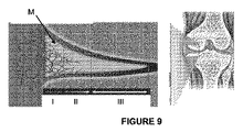
これらの画像は、おそらく半月板の血管に含まれるヘモグロビンに由来する、半月板の外側領域に光音響信号が存在することを示している。図9に示すように、最も血管新生が見込まれるのはこの外側の領域である。 These images show the presence of photoacoustic signals in the outer region of the meniscus, probably derived from hemoglobin contained in the blood vessels of the meniscus. As shown in FIG. 9, it is this outer region where the most angiogenesis is expected.
半月板は、大腿骨顆と脛骨プラトーの間に位置する半月状線維軟骨である。これらは、脛骨の前面および後面での前角および後角による固定、ならびにそれらの周辺縁による周方向の被膜靭帯固定を有する。これらは、さまざまな病変につながる可能性のある圧縮力、せん断力、ねじり力を受ける可動的かつ可変的な構造である。その機能としては、荷重分散、前方移動時の膝の安定化、関節の栄養と潤滑、固有受容などが知られる。 The meniscus is a crescent-shaped fibrocartilage located between the femoral condyle and the tibial plateau. They have anterior and dorsal horn fixation on the anterior and posterior surfaces of the tibia, as well as circumferential capsular ligament fixation by their peripheral edges. These are mobile and variable structures that are subject to compressive, shear and torsional forces that can lead to a variety of lesions. Known functions include load distribution, knee stabilization during anterior movement, joint nutrition and lubrication, and proprioception.
半月板の病変は頻度が高く、人口全体に影響を及ぼす。これらは、例えば外傷性および/または退行性であり、痛み、障害、関節浸出を引き起こす。その治療は単純であり、半月板の切除または修復からなる。 Meniscal lesions are common and affect the entire population. These are, for example, traumatic and / or degenerative, causing pain, disability, and joint exudation. The treatment is simple and consists of excision or repair of the meniscus.
半月板の切除(続発性変形性関節症の発症の可能性を伴う)を行う中長期の半月板切除術や前十字靭帯の再建を行った場合、医師は半月板を保存することが奨励される。実際、半月板が取り除かれると、その欠如は関節の劣化を加速させ、特に、若者を含むスポーツ愛好家(スキー、フットレース、サッカーなど)に対する早期の変形性関節症の発症に寄与する。半月板の保存は、膝の劣化を防ぎ、膝全体での人口膝関節の移植を可能な限り遅らせることができる。現時点では、半月板の病変で提案されている唯一の技術は縫合だが、文献では最大43%の失敗率が示されている(Pujol et al,“Amount Of meniscal resection after failed meniscal repair”,Am.J.Sports Med,2011)。予後を良好にするための主要な基準の1つは、損傷領域での(微小血管新生を構成する)毛細血管の視覚化である。この微小血管新生は、現時点では、手術条件下または術前画像では検出できない。病変は症例の50%以上が不確実性領域に位置しており、ほとんどの症例では、外科医の決定は、不確実な結果を伴う修復ではなく切除が優勢である。さらに、バットレス縫合はコストが高いため、手術室に備蓄されている量およびその使用は、管理された使用の対象となる。 Physicians are encouraged to preserve the meniscus when performing medium- to long-term meniscal resection with meniscal resection (with the potential for secondary osteoarthritis) or reconstruction of the anterior cruciate ligament. NS. In fact, when the meniscus is removed, its lack accelerates joint deterioration and contributes to the early development of osteoarthritis, especially for sports enthusiasts, including young people (skiing, foot racing, soccer, etc.). Preservation of the meniscus can prevent deterioration of the knee and delay the transplantation of the artificial knee joint throughout the knee as much as possible. At present, the only technique proposed for meniscal lesions is suturing, but the literature has shown a failure rate of up to 43% (Pujo et al, "Amount Of meniscal reduction after filed meniscal repair", Am. J. Sports Med, 2011). One of the key criteria for good prognosis is visualization of capillaries (constituting microangiogenesis) in the injured area. This microangiogenesis is currently undetectable under surgical conditions or on preoperative images. Lesions are located in areas of uncertainty in more than 50% of cases, and in most cases the surgeon's decision predominates resection rather than repair with uncertain consequences. In addition, due to the high cost of buttress sutures, the amount stockpiled in the operating room and its use are subject to controlled use.
図9は、半月板の異なる微小血管新生領域を概略的に示す断面図である。半月板の血管新生は、半月板の周辺(半月板壁)から起こるが、半月板の自由端では血管新生は起こらない。最も血管新生が促進される領域I(レッドゾーンとも呼ばれる)と、適度に血管新生される領域II(レッド−ホワイトゾーンとも呼ばれる)と、血管新生が起こらない領域III(ホワイトゾーンとも呼ばれる)の3つの領域を区別することができる。実際、領域Iで行われる縫合は、完全に治癒する可能性が高く、領域IIで行われる縫合は、ランダムに治癒する可能性がある。領域IIIで行われる縫合は、血管新生がないため失敗に終わる。 FIG. 9 is a cross-sectional view schematically showing different microangiogenic regions of the meniscus. Meniscal angiogenesis occurs around the meniscus (meniscus wall), but does not occur at the free end of the meniscus. Region I where angiogenesis is most promoted (also called red zone), region II where angiogenesis is moderately formed (also called red-white zone), and region III where angiogenesis does not occur (also called white zone) 3 Two areas can be distinguished. In fact, sutures made in region I are likely to heal completely, and sutures made in region II may heal randomly. Sutures performed in region III fail due to the absence of angiogenesis.
半月板損傷が半月板の末梢挿入部の近くにあり、長手方向の垂直面にある場合、半月板の修復が可能である。この縫合は、半月板の安定化と同じ一般的なモダリティに従って実行される。技術的には、吸収性アンカーを配置することで、縫合糸を固定することができる。半月板の修復は、特に若い被験者や前十字靭帯の断裂後に半月板病変を示した患者に見られる。安定した膝の半月板縫合により、十字靭帯だけでなく半月板の最良の状態での発展と治癒が可能となる。 If the meniscus tear is near the peripheral insertion of the meniscus and is in the longitudinal vertical plane, the meniscus can be repaired. This suture is performed according to the same general modality as meniscal stabilization. Technically, the suture can be fixed by placing an absorbent anchor. Meniscal repair is especially seen in younger subjects and patients who show meniscal lesions after rupture of the anterior cruciate ligament. Stable knee meniscal suture allows for best development and healing of the meniscus as well as the cruciate ligament.
内視鏡用光音響プローブは、外科医のために術中の意思決定支援ツールを提供し、微小血管新生に応じて、縫合が成功裏に実行され得るかどうかを高い確実性をもって決定することを可能にする。 Photoacoustic probes for endoscopy provide surgeons with intraoperative decision support tools that enable them to determine with high certainty whether sutures can be successfully performed in response to microangiogenesis. To.
実際、光音響は、ヘモグロビン(標的の毛細血管の特徴)を特異的に励起する可能性と、対象となる解剖学的構造(例えば、線維軟骨の半月板)の深部でその励起を検出するのに十分な感度を有する可能性との両方の利点を有する。プローブの使用は、半月板の修復または切除の決定を方向付けるための追加情報を提供するため、外科的行為の過程の一部である現在の慣行を補完する診断行為である。 In fact, photoacoustic has the potential to specifically excite hemoglobin (a characteristic of the target capillaries) and detect that excitation deep within the anatomy of interest (eg, the meniscus of fibrocartilage). Has both advantages with the possibility of having sufficient sensitivity to. The use of a probe is a diagnostic procedure that complements current practices that are part of the surgical procedure to provide additional information to direct the decision to repair or resect the meniscus.
同様の理由から、内視鏡用光音響プローブは、肩の回旋腱板の病変の治療にも関連する。実際、回旋腱板の血管新生は、病変の修復後の腱治癒における重要な要素の1つである。 For similar reasons, endoscopic photoacoustic probes are also associated with the treatment of lesions of the rotator cuff of the shoulder. In fact, rotator cuff angiogenesis is one of the key factors in tendon healing after lesion repair.
Claims (13)
前記カテーテルの先端(40)に設けられる超音波センサ(5)と、
レーザー光源に接続するのに適し、前記カテーテル内に前記先端(40)まで延在する少なくとも1つの光ファイバ(50)と
を備え、
前記カテーテルは、傾斜した先端部(42)および/または傾斜した先端(40)を有することを特徴とする、光音響超音波プローブ(100)。 Catheter (4) and
An ultrasonic sensor (5) provided at the tip (40) of the catheter and
Suitable for connecting to a laser light source, the catheter comprising at least one optical fiber (50) extending to the tip (40).
The catheter is a photoacoustic ultrasonic probe (100) characterized by having a sloping tip (42) and / or a sloping tip (40).
超音波ステーションに接続するのに適したコネクタ(1)と、
前記コネクタ(1)および前記制御ハンドル(2)の間に延在する電気接続ケーブル(3)と、
前記カテーテル(4)を覆い、超音波およびレーザービームを通過させるのに適した材料からなる第1の部分(10a)と、前記制御ハンドル(2)および前記電気接続ケーブル(3)を前記コネクタ(1)まで覆う第2の部分(10b)と、前記第1の部分および前記第2の部分の間に配置され、前記制御ハンドル(2)に着脱可能に取り付けられる取り付け具(11)とを含むシース(10)と
をさらに備える、請求項1から5のいずれか一項に記載の光音響超音波プローブ。 A control handle (2) attached to the proximal end (41) of the catheter,
A connector (1) suitable for connecting to an ultrasonic station,
An electrical connection cable (3) extending between the connector (1) and the control handle (2),
The connector (3) is connected to a first portion (10a) made of a material suitable for covering the catheter (4) and passing ultrasonic waves and laser beams, and the control handle (2) and the electrical connection cable (3). Includes a second portion (10b) that covers up to 1) and a fitting (11) that is disposed between the first portion and the second portion and is detachably attached to the control handle (2). The photoacoustic ultrasonic probe according to any one of claims 1 to 5, further comprising a sheath (10).
前記超音波ステーションに接続された請求項1から11のいずれか一項に記載の光音響超音波プローブと
を備え、
前記超音波ステーションは、前記光音響超音波プローブによって取得された対象の関節内領域の血管新生の画像を表示するように構成されたプロセッサを含む、イメージングシステム。 With an ultrasonic station containing a laser source,
The photoacoustic ultrasonic probe according to any one of claims 1 to 11 connected to the ultrasonic station is provided.
The ultrasound station is an imaging system comprising a processor configured to display an image of angiogenesis of an intra-articular region of interest acquired by the photoacoustic ultrasound probe.
Applications Claiming Priority (3)
| Application Number | Priority Date | Filing Date | Title |
|---|---|---|---|
| FR1854804A FR3081699B1 (en) | 2018-06-01 | 2018-06-01 | ENDOSCOPIC PHOTOACOUSTIC PROBE |
| FR1854804 | 2018-06-01 | ||
| PCT/FR2019/051294 WO2019229400A1 (en) | 2018-06-01 | 2019-06-03 | Endoscopic photoacoustic probe |
Publications (1)
| Publication Number | Publication Date |
|---|---|
| JP2021525603A true JP2021525603A (en) | 2021-09-27 |
Family
ID=63080131
Family Applications (1)
| Application Number | Title | Priority Date | Filing Date |
|---|---|---|---|
| JP2020567161A Pending JP2021525603A (en) | 2018-06-01 | 2019-06-03 | Photoacoustic probe for endoscopes |
Country Status (5)
| Country | Link |
|---|---|
| US (1) | US20210212570A1 (en) |
| EP (1) | EP3801214B1 (en) |
| JP (1) | JP2021525603A (en) |
| FR (1) | FR3081699B1 (en) |
| WO (1) | WO2019229400A1 (en) |
Families Citing this family (1)
| Publication number | Priority date | Publication date | Assignee | Title |
|---|---|---|---|---|
| CN116158720B (en) * | 2022-12-30 | 2023-11-21 | 深圳开立生物医疗科技股份有限公司 | Optical-photoacoustic-ultrasonic composite endoscope and endoscope system |
Citations (9)
| Publication number | Priority date | Publication date | Assignee | Title |
|---|---|---|---|---|
| JPH06134034A (en) * | 1992-10-23 | 1994-05-17 | Terumo Corp | Catheter tube |
| WO1995028129A1 (en) * | 1994-04-15 | 1995-10-26 | Tetrad Corporation | Bendable ultrasonic probe and sheath |
| WO2001022866A1 (en) * | 1999-09-28 | 2001-04-05 | Visionscope, Inc. | Endoscope system |
| US6592520B1 (en) * | 2001-07-31 | 2003-07-15 | Koninklijke Philips Electronics N.V. | Intravascular ultrasound imaging apparatus and method |
| US20100179432A1 (en) * | 2009-01-09 | 2010-07-15 | Boston Scientific Scimed, Inc. | Systems and methods for making and using intravascular ultrasound systems with photo-acoustic imaging capabilities |
| JP2011524794A (en) * | 2008-06-18 | 2011-09-08 | ボルケーノ・コーポレイション | Axial multi-wire barrel connector interconnecting control board to catheter containing tip mounted ultrasonic transducer assembly |
| JP2012513253A (en) * | 2008-12-22 | 2012-06-14 | アクラレント インコーポレイテッド | Frontal sinus spacer |
| US20130289369A1 (en) * | 2012-04-27 | 2013-10-31 | Volcano Corporation | Methods and Apparatus for Renal Neuromodulation |
| US20170273665A1 (en) * | 2016-03-28 | 2017-09-28 | Siemens Medical Solutions Usa, Inc. | Pose Recovery of an Ultrasound Transducer |
Family Cites Families (5)
| Publication number | Priority date | Publication date | Assignee | Title |
|---|---|---|---|---|
| CA2708743C (en) * | 2007-12-10 | 2016-08-30 | Stc.Unm | Photoacoustic imaging devices and methods of imaging |
| EP2671057B1 (en) * | 2011-02-04 | 2014-07-30 | Helmholtz Zentrum München Deutsches Forschungszentrum für Gesundheit und Umwelt (GmbH) | Ultrasound detector for optoacoustic or thermoacoustic imaging |
| JP6103931B2 (en) * | 2012-12-28 | 2017-03-29 | キヤノン株式会社 | Subject information acquisition apparatus and subject information acquisition method |
| US9439570B2 (en) * | 2013-03-15 | 2016-09-13 | Lx Medical Corporation | Tissue imaging and image guidance in luminal anatomic structures and body cavities |
| US20170280988A1 (en) * | 2014-04-02 | 2017-10-05 | Visionscope Technologies Llc | Devices and methods for minimally invasive surgery |
-
2018
- 2018-06-01 FR FR1854804A patent/FR3081699B1/en active Active
-
2019
- 2019-06-03 WO PCT/FR2019/051294 patent/WO2019229400A1/en unknown
- 2019-06-03 US US15/734,048 patent/US20210212570A1/en active Pending
- 2019-06-03 JP JP2020567161A patent/JP2021525603A/en active Pending
- 2019-06-03 EP EP19742436.9A patent/EP3801214B1/en active Active
Patent Citations (9)
| Publication number | Priority date | Publication date | Assignee | Title |
|---|---|---|---|---|
| JPH06134034A (en) * | 1992-10-23 | 1994-05-17 | Terumo Corp | Catheter tube |
| WO1995028129A1 (en) * | 1994-04-15 | 1995-10-26 | Tetrad Corporation | Bendable ultrasonic probe and sheath |
| WO2001022866A1 (en) * | 1999-09-28 | 2001-04-05 | Visionscope, Inc. | Endoscope system |
| US6592520B1 (en) * | 2001-07-31 | 2003-07-15 | Koninklijke Philips Electronics N.V. | Intravascular ultrasound imaging apparatus and method |
| JP2011524794A (en) * | 2008-06-18 | 2011-09-08 | ボルケーノ・コーポレイション | Axial multi-wire barrel connector interconnecting control board to catheter containing tip mounted ultrasonic transducer assembly |
| JP2012513253A (en) * | 2008-12-22 | 2012-06-14 | アクラレント インコーポレイテッド | Frontal sinus spacer |
| US20100179432A1 (en) * | 2009-01-09 | 2010-07-15 | Boston Scientific Scimed, Inc. | Systems and methods for making and using intravascular ultrasound systems with photo-acoustic imaging capabilities |
| US20130289369A1 (en) * | 2012-04-27 | 2013-10-31 | Volcano Corporation | Methods and Apparatus for Renal Neuromodulation |
| US20170273665A1 (en) * | 2016-03-28 | 2017-09-28 | Siemens Medical Solutions Usa, Inc. | Pose Recovery of an Ultrasound Transducer |
Also Published As
| Publication number | Publication date |
|---|---|
| FR3081699A1 (en) | 2019-12-06 |
| FR3081699B1 (en) | 2020-10-02 |
| EP3801214A1 (en) | 2021-04-14 |
| WO2019229400A1 (en) | 2019-12-05 |
| EP3801214B1 (en) | 2022-06-15 |
| US20210212570A1 (en) | 2021-07-15 |
Similar Documents
| Publication | Publication Date | Title |
|---|---|---|
| US11484209B1 (en) | Method of making a bone oxygenation measurement probe | |
| US10869725B2 (en) | Simulated method and system for navigating surgical instrument based on tomography | |
| US20210137602A1 (en) | Method to precisely place vertebral pedicle anchors during spinal fusion surgery | |
| JP2021525603A (en) | Photoacoustic probe for endoscopes | |
| Erdogan et al. | Reconstructive surgery of true aneurysm of the radial artery: a case report | |
| Cokluk et al. | Ultrasound examination in the surgical treatment of lower extremity peripheral nerve injuries: part II | |
| Lytton | Intraoperative ultrasound for nephrolithotomy | |
| Nyarady et al. | Osteoscopy for assessment of blood supply to the femoral head: a preliminary study | |
| RU2305493C1 (en) | Method of complex ultrasonic diagnostics of injury of internal meniscus of knee joint in area of body and anterior horn | |
| Rosenberg et al. | Intraosseous monitoring and guiding by ultrasound: a feasibility study | |
| JP2021526412A (en) | Ultrasonic probe for endoscope and sheath for the probe | |
| Kantelhardt et al. | Intraosseous ultrasonography to determine the accuracy of drill hole positioning prior to the placement of pedicle screws: an experimental study | |
| RU2754953C1 (en) | Method for preoperative planning of surgical tactics for ruptures of the achilles tendon | |
| Sökmen et al. | How useful is elastography in the follow-up of achilles tendon repair? | |
| Shih et al. | Augmenting the Reliability and Versatility of Medial Sural Artery Perforator Flap | |
| JP2016524948A (en) | Surgical instruments and methods of use | |
| US8332014B2 (en) | Scanned beam device and method using same which measures the reflectance of patient tissue | |
| RU2284149C2 (en) | Method for detecting the depth and the scope of osteonecrosis in patients with initial stages of knee joint's osteochondritis dissecans for carrying out arthroscopic operations | |
| Jonas et al. | 3D color doppler ultrasound for postoperative monitoring of vascularized lymph node flaps | |
| Murata et al. | Ganglion cysts arising from a canine stifle joint | |
| Stieger‐Vanegas | POCUS: Musculoskeletal–Bones and Joints | |
| Dekhnych et al. | The nature of abdominal surgery for polycystic kidney disease in animals and the role of sonographic indicators at different stages of surgical intervention: A literature review. | |
| RU2201142C2 (en) | Method for evaluating regeneration activity of distraction regenerate | |
| Xu et al. | Quantitative Assessment of Nerve Root Decompression During Lumbar Surgery: A Prospective Application of Contrast-Enhanced Ultrasound | |
| Sugamoto et al. | Colour Doppler analysis of tendon and muscle movements |
Legal Events
| Date | Code | Title | Description |
|---|---|---|---|
| A621 | Written request for application examination |
Free format text: JAPANESE INTERMEDIATE CODE: A621 Effective date: 20220520 |
|
| A131 | Notification of reasons for refusal |
Free format text: JAPANESE INTERMEDIATE CODE: A131 Effective date: 20221206 |
|
| A02 | Decision of refusal |
Free format text: JAPANESE INTERMEDIATE CODE: A02 Effective date: 20230627 |