JP2021524916A - Force Sensing Resistors (FSRs) with Polyimide Substrates, Systems, and Methods - Google Patents
Force Sensing Resistors (FSRs) with Polyimide Substrates, Systems, and Methods Download PDFInfo
- Publication number
- JP2021524916A JP2021524916A JP2020564742A JP2020564742A JP2021524916A JP 2021524916 A JP2021524916 A JP 2021524916A JP 2020564742 A JP2020564742 A JP 2020564742A JP 2020564742 A JP2020564742 A JP 2020564742A JP 2021524916 A JP2021524916 A JP 2021524916A
- Authority
- JP
- Japan
- Prior art keywords
- substrate
- fsr
- controller
- coverlay
- force
- Prior art date
- Legal status (The legal status is an assumption and is not a legal conclusion. Google has not performed a legal analysis and makes no representation as to the accuracy of the status listed.)
- Pending
Links
- 239000000758 substrate Substances 0.000 title claims abstract description 228
- 239000004642 Polyimide Substances 0.000 title claims abstract description 47
- 229920001721 polyimide Polymers 0.000 title claims abstract description 47
- 238000000034 method Methods 0.000 title claims description 55
- 239000010410 layer Substances 0.000 claims description 74
- 239000000463 material Substances 0.000 claims description 67
- 239000012790 adhesive layer Substances 0.000 claims description 57
- RYGMFSIKBFXOCR-UHFFFAOYSA-N Copper Chemical compound [Cu] RYGMFSIKBFXOCR-UHFFFAOYSA-N 0.000 claims description 55
- 229910052802 copper Inorganic materials 0.000 claims description 55
- 239000010949 copper Substances 0.000 claims description 55
- 239000002184 metal Substances 0.000 claims description 45
- 229910052751 metal Inorganic materials 0.000 claims description 45
- 239000004020 conductor Substances 0.000 claims description 37
- 125000006850 spacer group Chemical group 0.000 claims description 20
- 229910052737 gold Inorganic materials 0.000 claims description 15
- 239000010931 gold Substances 0.000 claims description 15
- PCHJSUWPFVWCPO-UHFFFAOYSA-N gold Chemical compound [Au] PCHJSUWPFVWCPO-UHFFFAOYSA-N 0.000 claims description 14
- 238000004519 manufacturing process Methods 0.000 claims description 10
- 238000001514 detection method Methods 0.000 claims description 9
- 230000002093 peripheral effect Effects 0.000 claims description 6
- 238000005530 etching Methods 0.000 claims description 5
- 238000010276 construction Methods 0.000 claims description 3
- 238000000151 deposition Methods 0.000 claims description 3
- 238000009825 accumulation Methods 0.000 claims 1
- 229920005560 fluorosilicone rubber Polymers 0.000 abstract 1
- 210000003811 finger Anatomy 0.000 description 62
- 230000008569 process Effects 0.000 description 43
- 239000000853 adhesive Substances 0.000 description 40
- 230000001070 adhesive effect Effects 0.000 description 40
- 210000003128 head Anatomy 0.000 description 35
- 230000004044 response Effects 0.000 description 20
- 230000009471 action Effects 0.000 description 17
- 230000027455 binding Effects 0.000 description 17
- 238000009739 binding Methods 0.000 description 17
- 230000007246 mechanism Effects 0.000 description 13
- 238000007747 plating Methods 0.000 description 13
- 230000000875 corresponding effect Effects 0.000 description 12
- 230000006870 function Effects 0.000 description 12
- 239000004033 plastic Substances 0.000 description 12
- 229920003023 plastic Polymers 0.000 description 12
- 210000003813 thumb Anatomy 0.000 description 12
- 239000003351 stiffener Substances 0.000 description 11
- 229920002799 BoPET Polymers 0.000 description 9
- 239000005041 Mylar™ Substances 0.000 description 9
- 230000015654 memory Effects 0.000 description 9
- 238000010586 diagram Methods 0.000 description 7
- 230000005670 electromagnetic radiation Effects 0.000 description 7
- 230000004927 fusion Effects 0.000 description 6
- 239000012779 reinforcing material Substances 0.000 description 6
- 238000003860 storage Methods 0.000 description 6
- 230000004913 activation Effects 0.000 description 5
- 238000004891 communication Methods 0.000 description 5
- 230000007423 decrease Effects 0.000 description 5
- 210000001331 nose Anatomy 0.000 description 5
- 230000014759 maintenance of location Effects 0.000 description 4
- 238000003825 pressing Methods 0.000 description 4
- 238000005476 soldering Methods 0.000 description 4
- 239000004820 Pressure-sensitive adhesive Substances 0.000 description 3
- 230000003213 activating effect Effects 0.000 description 3
- 230000006399 behavior Effects 0.000 description 3
- 230000008901 benefit Effects 0.000 description 3
- 230000003247 decreasing effect Effects 0.000 description 3
- 230000005057 finger movement Effects 0.000 description 3
- 239000000203 mixture Substances 0.000 description 3
- 239000004417 polycarbonate Substances 0.000 description 3
- 238000012545 processing Methods 0.000 description 3
- 230000003014 reinforcing effect Effects 0.000 description 3
- 230000035945 sensitivity Effects 0.000 description 3
- 239000007787 solid Substances 0.000 description 3
- 238000013519 translation Methods 0.000 description 3
- PXHVJJICTQNCMI-UHFFFAOYSA-N Nickel Chemical compound [Ni] PXHVJJICTQNCMI-UHFFFAOYSA-N 0.000 description 2
- 238000003491 array Methods 0.000 description 2
- 230000008859 change Effects 0.000 description 2
- 230000001276 controlling effect Effects 0.000 description 2
- 238000007796 conventional method Methods 0.000 description 2
- 230000007123 defense Effects 0.000 description 2
- 230000001934 delay Effects 0.000 description 2
- 238000013461 design Methods 0.000 description 2
- 238000005516 engineering process Methods 0.000 description 2
- 239000004744 fabric Substances 0.000 description 2
- 210000004247 hand Anatomy 0.000 description 2
- 208000013057 hereditary mucoepithelial dysplasia Diseases 0.000 description 2
- 238000001746 injection moulding Methods 0.000 description 2
- 230000003993 interaction Effects 0.000 description 2
- 238000005259 measurement Methods 0.000 description 2
- 230000003278 mimic effect Effects 0.000 description 2
- 230000003287 optical effect Effects 0.000 description 2
- 239000003973 paint Substances 0.000 description 2
- 239000011435 rock Substances 0.000 description 2
- OKTJSMMVPCPJKN-UHFFFAOYSA-N Carbon Chemical compound [C] OKTJSMMVPCPJKN-UHFFFAOYSA-N 0.000 description 1
- 101000822695 Clostridium perfringens (strain 13 / Type A) Small, acid-soluble spore protein C1 Proteins 0.000 description 1
- 101000655262 Clostridium perfringens (strain 13 / Type A) Small, acid-soluble spore protein C2 Proteins 0.000 description 1
- 241000699666 Mus <mouse, genus> Species 0.000 description 1
- 241000699670 Mus sp. Species 0.000 description 1
- 239000004677 Nylon Substances 0.000 description 1
- 101000655256 Paraclostridium bifermentans Small, acid-soluble spore protein alpha Proteins 0.000 description 1
- 101000655264 Paraclostridium bifermentans Small, acid-soluble spore protein beta Proteins 0.000 description 1
- 239000004698 Polyethylene Substances 0.000 description 1
- BQCADISMDOOEFD-UHFFFAOYSA-N Silver Chemical compound [Ag] BQCADISMDOOEFD-UHFFFAOYSA-N 0.000 description 1
- 230000000903 blocking effect Effects 0.000 description 1
- 229910052799 carbon Inorganic materials 0.000 description 1
- 239000003795 chemical substances by application Substances 0.000 description 1
- 238000005352 clarification Methods 0.000 description 1
- 230000002596 correlated effect Effects 0.000 description 1
- 230000008021 deposition Effects 0.000 description 1
- 230000009977 dual effect Effects 0.000 description 1
- 230000000694 effects Effects 0.000 description 1
- 230000005489 elastic deformation Effects 0.000 description 1
- 239000012777 electrically insulating material Substances 0.000 description 1
- 230000005284 excitation Effects 0.000 description 1
- 150000002343 gold Chemical class 0.000 description 1
- 238000007654 immersion Methods 0.000 description 1
- 230000000977 initiatory effect Effects 0.000 description 1
- 238000003780 insertion Methods 0.000 description 1
- 230000037431 insertion Effects 0.000 description 1
- 238000012544 monitoring process Methods 0.000 description 1
- 229910052759 nickel Inorganic materials 0.000 description 1
- 230000003121 nonmonotonic effect Effects 0.000 description 1
- 229920001778 nylon Polymers 0.000 description 1
- 230000010355 oscillation Effects 0.000 description 1
- 229920001084 poly(chloroprene) Polymers 0.000 description 1
- 229920000515 polycarbonate Polymers 0.000 description 1
- -1 polyethylene Polymers 0.000 description 1
- 229920000573 polyethylene Polymers 0.000 description 1
- 230000036316 preload Effects 0.000 description 1
- 238000011084 recovery Methods 0.000 description 1
- 239000004065 semiconductor Substances 0.000 description 1
- 230000035807 sensation Effects 0.000 description 1
- 230000001568 sexual effect Effects 0.000 description 1
- 229910052709 silver Inorganic materials 0.000 description 1
- 239000004332 silver Substances 0.000 description 1
- 238000001228 spectrum Methods 0.000 description 1
- 238000012549 training Methods 0.000 description 1
- 238000012546 transfer Methods 0.000 description 1
Images


Classifications
-
- G—PHYSICS
- G01—MEASURING; TESTING
- G01L—MEASURING FORCE, STRESS, TORQUE, WORK, MECHANICAL POWER, MECHANICAL EFFICIENCY, OR FLUID PRESSURE
- G01L1/00—Measuring force or stress, in general
- G01L1/20—Measuring force or stress, in general by measuring variations in ohmic resistance of solid materials or of electrically-conductive fluids; by making use of electrokinetic cells, i.e. liquid-containing cells wherein an electrical potential is produced or varied upon the application of stress
- G01L1/205—Measuring force or stress, in general by measuring variations in ohmic resistance of solid materials or of electrically-conductive fluids; by making use of electrokinetic cells, i.e. liquid-containing cells wherein an electrical potential is produced or varied upon the application of stress using distributed sensing elements
-
- A—HUMAN NECESSITIES
- A63—SPORTS; GAMES; AMUSEMENTS
- A63F—CARD, BOARD, OR ROULETTE GAMES; INDOOR GAMES USING SMALL MOVING PLAYING BODIES; VIDEO GAMES; GAMES NOT OTHERWISE PROVIDED FOR
- A63F13/00—Video games, i.e. games using an electronically generated display having two or more dimensions
- A63F13/20—Input arrangements for video game devices
- A63F13/21—Input arrangements for video game devices characterised by their sensors, purposes or types
- A63F13/218—Input arrangements for video game devices characterised by their sensors, purposes or types using pressure sensors, e.g. generating a signal proportional to the pressure applied by the player
-
- A—HUMAN NECESSITIES
- A63—SPORTS; GAMES; AMUSEMENTS
- A63F—CARD, BOARD, OR ROULETTE GAMES; INDOOR GAMES USING SMALL MOVING PLAYING BODIES; VIDEO GAMES; GAMES NOT OTHERWISE PROVIDED FOR
- A63F13/00—Video games, i.e. games using an electronically generated display having two or more dimensions
- A63F13/20—Input arrangements for video game devices
- A63F13/24—Constructional details thereof, e.g. game controllers with detachable joystick handles
-
- G—PHYSICS
- G01—MEASURING; TESTING
- G01L—MEASURING FORCE, STRESS, TORQUE, WORK, MECHANICAL POWER, MECHANICAL EFFICIENCY, OR FLUID PRESSURE
- G01L1/00—Measuring force or stress, in general
- G01L1/20—Measuring force or stress, in general by measuring variations in ohmic resistance of solid materials or of electrically-conductive fluids; by making use of electrokinetic cells, i.e. liquid-containing cells wherein an electrical potential is produced or varied upon the application of stress
-
- G—PHYSICS
- G06—COMPUTING; CALCULATING OR COUNTING
- G06F—ELECTRIC DIGITAL DATA PROCESSING
- G06F3/00—Input arrangements for transferring data to be processed into a form capable of being handled by the computer; Output arrangements for transferring data from processing unit to output unit, e.g. interface arrangements
- G06F3/01—Input arrangements or combined input and output arrangements for interaction between user and computer
- G06F3/03—Arrangements for converting the position or the displacement of a member into a coded form
- G06F3/041—Digitisers, e.g. for touch screens or touch pads, characterised by the transducing means
- G06F3/0416—Control or interface arrangements specially adapted for digitisers
- G06F3/04166—Details of scanning methods, e.g. sampling time, grouping of sub areas or time sharing with display driving
-
- G—PHYSICS
- G06—COMPUTING; CALCULATING OR COUNTING
- G06F—ELECTRIC DIGITAL DATA PROCESSING
- G06F3/00—Input arrangements for transferring data to be processed into a form capable of being handled by the computer; Output arrangements for transferring data from processing unit to output unit, e.g. interface arrangements
- G06F3/01—Input arrangements or combined input and output arrangements for interaction between user and computer
- G06F3/03—Arrangements for converting the position or the displacement of a member into a coded form
- G06F3/041—Digitisers, e.g. for touch screens or touch pads, characterised by the transducing means
- G06F3/045—Digitisers, e.g. for touch screens or touch pads, characterised by the transducing means using resistive elements, e.g. a single continuous surface or two parallel surfaces put in contact
-
- H—ELECTRICITY
- H01—ELECTRIC ELEMENTS
- H01C—RESISTORS
- H01C10/00—Adjustable resistors
- H01C10/10—Adjustable resistors adjustable by mechanical pressure or force
-
- G—PHYSICS
- G06—COMPUTING; CALCULATING OR COUNTING
- G06F—ELECTRIC DIGITAL DATA PROCESSING
- G06F2203/00—Indexing scheme relating to G06F3/00 - G06F3/048
- G06F2203/041—Indexing scheme relating to G06F3/041 - G06F3/045
- G06F2203/04105—Pressure sensors for measuring the pressure or force exerted on the touch surface without providing the touch position
-
- G—PHYSICS
- G06—COMPUTING; CALCULATING OR COUNTING
- G06F—ELECTRIC DIGITAL DATA PROCESSING
- G06F2203/00—Indexing scheme relating to G06F3/00 - G06F3/048
- G06F2203/041—Indexing scheme relating to G06F3/041 - G06F3/045
- G06F2203/04108—Touchless 2D- digitiser, i.e. digitiser detecting the X/Y position of the input means, finger or stylus, also when it does not touch, but is proximate to the digitiser's interaction surface without distance measurement in the Z direction
-
- H—ELECTRICITY
- H01—ELECTRIC ELEMENTS
- H01C—RESISTORS
- H01C10/00—Adjustable resistors
- H01C10/10—Adjustable resistors adjustable by mechanical pressure or force
- H01C10/106—Adjustable resistors adjustable by mechanical pressure or force on resistive material dispersed in an elastic material
-
- H—ELECTRICITY
- H01—ELECTRIC ELEMENTS
- H01C—RESISTORS
- H01C10/00—Adjustable resistors
- H01C10/10—Adjustable resistors adjustable by mechanical pressure or force
- H01C10/12—Adjustable resistors adjustable by mechanical pressure or force by changing surface pressure between resistive masses or resistive and conductive masses, e.g. pile type
Landscapes
- Engineering & Computer Science (AREA)
- Multimedia (AREA)
- Human Computer Interaction (AREA)
- General Engineering & Computer Science (AREA)
- Theoretical Computer Science (AREA)
- Physics & Mathematics (AREA)
- General Physics & Mathematics (AREA)
- Microelectronics & Electronic Packaging (AREA)
- Position Input By Displaying (AREA)
- User Interface Of Digital Computer (AREA)
Abstract
抵抗性で可撓性のある第2の基板の下に配置されたポリイミド製の第1の基板で構成される力検知抵抗器(FSR)。電子システム用のハンドヘルドコントローラは、ポリイミドで作られた第1の基板を有するFSRを含むことができる。FSRは、コントローラ本体のハンドル内に取り付けられる構造、および/またはコントローラ本体のヘッドに含まれる少なくとも1つの親指操作式コントロールの下方に取り付けられる構造など、コントローラ本体内の構造の平面に取り付けられることができる。FSRは、ハンドルの外面に加えられる力の量、および/または少なくとも1つの親指操作式コントロールに加えられる力の量に対応する抵抗値を測定するように構成されることができる。A force-sensing resistor (FSR) composed of a first substrate made of polyimide placed under a second substrate that is resistant and flexible. Handheld controllers for electronic systems can include FSRs with a first substrate made of polyimide. The FSR may be mounted on a flat surface of the structure within the controller body, such as a structure mounted within the handle of the controller body and / or a structure mounted below at least one thumb-operated control contained in the head of the controller body. can. The FSR can be configured to measure the amount of force applied to the outer surface of the handle and / or the resistance value corresponding to the amount of force applied to at least one thumb-operated control.
Description
これは、2017年6月16日に出願された米国仮特許出願第62/520,958号の優先権を主張する、それ自体が2016年10月11日に出願された米国特許出願第29/580,635号の一部継続として優先権を主張する、それ自体が2017年8月17日に出願された「ハンドリテーナおよび指のモーション検知を備えた電子コントローラ」と題された米国特許出願第15/679,521号の一部継続として優先権を主張する、2017年12月7日に出願された「指検知による電子コントローラおよび調整可能なハンドリテーナ」と題された係属中の米国特許出願第15/834,372号の一部継続として優先権を主張する、2018年5月18日に出願された「ポリイミド基板を備えた力検知抵抗器(FSR)、システム、およびその方法」と題された米国特許出願第15/984,231号の優先権を主張するPCT出願であり、これらの全ては、参照によりその全体が組み込まれる。 This claims the priority of US Provisional Patent Application No. 62 / 520,958 filed on June 16, 2017, which itself is filed on October 11, 2016, US Patent Application No. 29 / US Patent Application No. 580, 635, claiming priority as a partial continuation, itself entitled "Electronic Controller with Hand Retainer and Finger Motion Detection" filed on August 17, 2017. A pending US patent application entitled "Finger-Detected Electronic Controller and Adjustable Hand Retainer" filed December 7, 2017, claiming priority as a partial continuation of 15 / 679,521. Claiming priority as a partial continuation of No. 15 / 834,372, filed May 18, 2018, entitled "Force Sensing Resistors with Polygonal Substrates (FSRs), Systems, and Methods" It is a PCT application claiming the priority of US Patent Application No. 15 / 984,231, all of which are incorporated by reference in their entirety.
ビデオゲーム業界は、大きく重要になり、ソフトウェアおよび関連ハードウェアの双方で多くの革新を生み出してきた。様々なゲームアプリケーション向けに、様々なハンドヘルドビデオゲームコントローラが設計、製造、販売されている。これらの革新の一部は、産業用機械、防衛システム、ロボット工学などのコントローラなど、ビデオゲーム業界以外にも適用可能である。仮想現実(VR)システムは、ビデオゲーム業界の内外双方において現代の大きな関心と急速な技術進歩のアプリケーションである。VRシステムのコントローラは、いくつかの異なる機能を実行する必要があり、多くの場合、使いやすさなどの特定の望ましい特性を最適化しながら、厳密な(場合によっては競合する)設計上の制約を満たす必要がある。 The video game industry has become very important and has created many innovations in both software and related hardware. Various handheld video game controllers are designed, manufactured and sold for a variety of gaming applications. Some of these innovations are applicable outside the video gaming industry, including controllers for industrial machinery, defense systems, robotics, and more. Virtual reality (VR) systems are an application of great modern interest and rapid technological advancement both inside and outside the video game industry. The controller of a VR system needs to perform several different functions, often with strict (possibly competing) design constraints while optimizing certain desirable characteristics such as ease of use. Need to meet.
VRシステムで使用されるコントローラの目的の1つは、つかむ、投げる、絞るなどの自然な相互作用を可能な限り模倣することである。この目的を満たす努力において、とりわけ、可変抵抗を使用してFSRに加えられた力の量を測定する力検知抵抗器(FSR)を含む、様々なタイプのセンサが利用されてきた。しかしながら、FSRを備えた既存のコントローラは、その構造に使用されている材料のために、かなり粗い応答曲線(例えば、力対抵抗応答曲線)を示す傾向があり、バイナリ(例えば、オン/オフ)スイッチにすぎない場合に役立つ。これは、VRシステムでは望ましくない。さらに、マイラーベースのFSRは、大きくてかさばるヘッダーコネクタを必要とし、これは、FSRのフットプリントが大きく、小型化が難しく、他の構成要素に直接はんだ付けすることができないことを意味する。FSRの構築にマイラーを使用することのさらに別の欠点は、リフローオーブンの高温に耐えられないことであり、これは、マイラーベースのFSRの製造コストを削減する方法を制限する。下部基板にマイラーを使用する代わりに、下部基板としてプリント回路基板(PCB)を使用してFSRを構築することも知られている。しかしながら、PCB基板はまた、粗い(場合によっては非単調な)応答曲線も示すため、これらのタイプのFSRは、VRアプリケーションには不適切である。したがって、当該技術分野では、VRシステムを改善し、および/またはユーザ操作をより容易にすることができる改善されたコントローラ設計が必要とされている。 One of the purposes of the controller used in a VR system is to mimic as much as possible natural interactions such as grabbing, throwing, and squeezing. In an effort to meet this goal, various types of sensors have been utilized, among others, including force sensing resistors (FSRs) that use variable resistors to measure the amount of force applied to the FSR. However, existing controllers with FSR tend to show a fairly coarse response curve (eg, force-to-resistance response curve) due to the materials used in their construction, and are binary (eg, on / off). Useful if it's just a switch. This is not desirable in VR systems. In addition, Mylar-based FSRs require large and bulky header connectors, which means that the FSRs have a large footprint, are difficult to miniaturize, and cannot be soldered directly to other components. Yet another drawback of using Mylar to build FSRs is that they cannot withstand the high temperatures of reflow ovens, which limits the way we can reduce the cost of manufacturing Mylar-based FSRs. It is also known to build an FSR using a printed circuit board (PCB) as the lower board instead of using Mylar as the lower board. However, PCB substrates also show a rough (possibly non-monotonic) response curve, making these types of FSRs unsuitable for VR applications. Therefore, there is a need for improved controller designs that can improve the VR system and / or make user operation easier in the art.
本明細書で説明されるのは、とりわけ、抵抗性で可撓性のある第2の基板の下に配置されたポリイミド製の第1の基板で構成される力検知抵抗器(FSR)である。第1の基板は、その前面に配置された導電性材料(例えば、複数の互いに噛み合った金属フィンガ)を有する。第2の基板の中央部分が第1の基板上に懸架されるように、1つ以上のスペーサ層も第1の基板と第2の基板との間に挿入される。アクチュエータは、第2の基板上に配置され、加えられた力を第2の基板の前面に伝達する。これが起こると、第2の基板の中央部分が第1の基板に向かって内側に屈曲し、第2の基板の裏面の抵抗性材料の一部が、第1の基板の前面の導電性材料の一部と接触する。加えられる力が増加するにつれて、抵抗性材料が接触する導電性材料の表面積が増加する。同様に、加えられる力が減少するにつれて、抵抗性材料が接触する導電性材料の表面積が減少する。可変の加えられた力の下での表面積接触のこの変化は、FSRを、加えられた力によって値が制御される可変抵抗器として機能させる。 Described herein are, among other things, a force-sensing resistor (FSR) composed of a first substrate made of polyimide placed beneath a second substrate that is resistant and flexible. .. The first substrate has a conductive material (eg, a plurality of metal fingers meshing with each other) arranged in front of the substrate. One or more spacer layers are also inserted between the first substrate and the second substrate so that the central portion of the second substrate is suspended over the first substrate. The actuator is placed on the second substrate and transmits the applied force to the front surface of the second substrate. When this happens, the central portion of the second substrate bends inward toward the first substrate, and some of the resistant material on the back surface of the second substrate is made of the conductive material on the front surface of the first substrate. Contact some. As the force applied increases, the surface area of the conductive material with which the resistant material comes into contact increases. Similarly, as the applied force decreases, the surface area of the conductive material that the resistant material comes into contact with decreases. This change in surface area contact under a variable applied force causes the FSR to function as a variable resistor whose value is controlled by the applied force.
少なくとも部分的には第1の基板に使用されるポリイミド材料のために、開示されたFSRは、他の可能な最終用途の中で、VRシステムのコントローラでの使用に望ましい特性を示す。例えば、ポリイミド基板を使用すると、かさばるヘッダーコネクタを使用せずに、FSRの出力端子(またはリード)を基板(例えば、PCB)に直接選択的にはんだ付けすることを可能にし、これにより、大きくてかさばるヘッダーコネクタを必要とするマイラーベースのFSRと比較して、FSRのフットプリントを小さくすることができる。ポリイミドは、フレックス回路の選択材料として一般的に使用されているため、FSRのポリイミド基板を使用すると、FSRを他のフレックス回路に簡単に接続することができ、従来のFSRの製造コストと比較して、開示されたFSRの製造コストを削減することができる。ポリイミドはまた、リフローオーブンなどの高温にも耐えることができ、コスト削減の製造プロセスへの扉を開く。さらに、ポリイミドは、開示されたFSRの第1の基板として使用される場合、従来のFSRと比較して、ヒステリシスが少なく、再現性が高いなどの望ましい特性を示す。全体として、ポリイミドで作られた第1の基板を有する開示されたFSRは、真のアナログ入力をモデル化する力対抵抗応答曲線を示し、FSRをVRシステムのコントローラでの使用に望ましいものにする。 Due to the polyimide material used in the first substrate, at least in part, the disclosed FSR exhibits desirable properties for use in the controller of a VR system, among other possible end applications. For example, a polyimide substrate allows the output terminals (or leads) of an FSR to be selectively soldered directly to a substrate (eg, a PCB) without the use of bulky header connectors, which allows for large. The footprint of the FSR can be reduced compared to a Mylar-based FSR that requires a bulky header connector. Since polyimide is commonly used as a material of choice for flex circuits, the FSR polyimide substrate allows the FSR to be easily connected to other flex circuits, compared to the manufacturing costs of conventional FSRs. Therefore, the manufacturing cost of the disclosed FSR can be reduced. Polyimide can also withstand high temperatures such as reflow ovens, opening the door to cost-saving manufacturing processes. Further, when the polyimide is used as the first substrate of the disclosed FSR, it exhibits desirable characteristics such as less hysteresis and higher reproducibility as compared with the conventional FSR. Overall, the disclosed FSR with a first substrate made of polyimide shows a force-to-resistance response curve that models a true analog input, making the FSR desirable for use in the controller of a VR system. ..
また、本明細書に開示されるのは、ポリイミドで作られた第1の基板を有する開示されたFSRを含む電子システム(例えば、VRシステム)のためのコントローラである。コントローラは、ユーザの手によって保持されるように構成されることができ、コントローラ本体を含むことができる。開示されたFSRは、コントローラ本体のハンドル内に取り付けられる構造、またはコントローラ本体のヘッドに含まれる少なくとも1つの親指操作式コントローラの下方に取り付けられる構造など、コントローラ本体内の構造の平面に取り付けることができる。FSRは、電子システムのコントローラに実装されると、コントローラの関連部分に加えられる力の量に対応する抵抗値を測定するように構成される(例えば、ハンドルの外面に加えられる力は、少なくとも1つの親指操作コントロールになど)。 Also disclosed herein is a controller for an electronic system (eg, a VR system) that includes a disclosed FSR that has a first substrate made of polyimide. The controller can be configured to be held by the user's hands and can include the controller body. The disclosed FSR may be mounted on a flat surface of the structure within the controller body, such as a structure mounted within the handle of the controller body or below at least one thumb-operated controller contained in the head of the controller body. can. When implemented in a controller of an electronic system, the FSR is configured to measure a resistance value that corresponds to the amount of force applied to the relevant part of the controller (eg, the force applied to the outer surface of the handle is at least 1). For one thumb operation control etc.).
VRシステムのコントローラにFSRを実装すると、従来のコントローラを使用して、現在の状態を超えて自然な相互作用のスペクトルを拡大することができる。例えば、電子システムおよび/またはコントローラは、FSRを介して、ユーザがコントローラのハンドルを握る力、および/またはユーザが親指操作の制御装置を押す力を決定することができる。開示されたFSRは望ましい応答曲線を示すため、そのようなコントローラは、様々な力の押圧または圧搾を、ビデオゲームがゲームメカニックを制御するために(例えば、岩を砕くために、バルーンを圧搾するために、ゲームキャラクタが使用できる武器を切り替えるために)使用できる様々なデジタル化された数値に変換することができる。望ましい応答特性を備えたFSRは、ユーザの疲労を軽減するため、および/またはコントロールの偶発的な作動を軽減するために、従来の機械式スイッチを置き換えることができる。例えば、FSRは、加えられた力が閾値を超えたことを検出することにより、スイッチとして機能することができる。この閾値は動的に調整される。例えば、ゲームプレイ中の手の疲労を軽減するために、閾値を低い値に調整することができる(例えば、ユーザがFSRに関連付けられたコントロールを押して、ゲームプレイ中に頻繁に武器を撃つ場合)。逆に、偶発的なコントロール操作のインスタンスを減らすために、閾値をより高い値に調整することができ、これは、ユーザがビデオゲームの刺激に反応する可能性があるスリリングまたはエキサイティングなゲームで役立つことができる。 When the FSR is implemented in the controller of a VR system, a conventional controller can be used to extend the spectrum of natural interactions beyond the current state. For example, the electronic system and / or the controller can determine, via the FSR, the force with which the user grips the handle of the controller and / or the force with which the user pushes the thumb-operated controller. Since the disclosed FSR shows the desired response curve, such a controller squeezes a balloon with various force presses or squeezes for the video game to control the game mechanic (eg, to crush rocks). Therefore, it can be converted into various digitized numbers that can be used (to switch the weapons that the game character can use). The FSR with the desired response characteristics can replace conventional mechanical switches to reduce user fatigue and / or to reduce accidental operation of the control. For example, the FSR can function as a switch by detecting that the applied force exceeds a threshold. This threshold is dynamically adjusted. For example, the threshold can be adjusted to a lower value to reduce hand fatigue during gameplay (eg, if the user presses a control associated with the FSR and shoots a weapon frequently during gameplay). .. Conversely, the threshold can be adjusted to a higher value to reduce the number of instances of accidental control operations, which is useful in thrilling or exciting games where the user may respond to video game stimuli. be able to.
また、本明細書に開示されるのは、タッチセンサまたは近接センサのアレイによってそれぞれ提供されるタッチデータまたは近接データと組み合わせたコントローラのFSRによって提供される力データに基づいてセンサ融合アルゴリズムを実装するためのロジックを含むハンドヘルドコントローラである。センサ融合アルゴリズムの例を使用して、タッチセンサによって検出されたように、オブジェクトがFSRに関連付けられたコントロールに接触したときにFSRを再校正することができる。例えば、ロジックは、タッチセンサによって提供されるタッチデータに基づいて、オブジェクトが、押されるように構成されたコントローラ本体上のコントロールと接触したことを判定することができる。ロジックはまた、オブジェクトがコントロールと接触したときにFSRによって提供された力データに基づいて、FSRによって測定された抵抗値を判定し、コントロールでのタッチを検出すると、FSRを「再校正」するために、抵抗値をデジタル化されたゼロのFSR入力値と相関させることができる。 Also disclosed herein is to implement a sensor fusion algorithm based on the force data provided by the controller's FSR in combination with the touch data or proximity data provided by the array of touch sensors or proximity sensors, respectively. A handheld controller that contains the logic for. An example of a sensor fusion algorithm can be used to recalibrate the FSR when the object touches the control associated with the FSR, as detected by the touch sensor. For example, logic can determine that an object has come into contact with a control on the controller body that is configured to be pressed, based on the touch data provided by the touch sensor. The logic also determines the resistance value measured by the FSR based on the force data provided by the FSR when the object touches the control, and when it detects a touch on the control, it "recalibrates" the FSR. In addition, the resistance value can be correlated with the digitized zero FSR input value.
別のセンサ融合アルゴリズムの例を使用して、オブジェクトが隣接するコントロールと接触しているときにFSRによって検出された偽入力を無視することができる。例えば、ロジックは、FSRによって提供される力データに基づいて、ハンドヘルドコントローラの第1のコントロールのFSR入力イベントを登録するために満たされるべき閾値を満たすかまたは超えるデジタル化されたFSR入力値に対応するFSRによって測定される抵抗値を判定することができる。ロジックはまた、FSR抵抗値がFSRによって測定されるときにタッチセンサによって提供されるタッチデータに基づいて、オブジェクトが、第1のコントロールに隣接するハンドヘルドコントローラの第2のコントロールと接触していることを判定することができ、オブジェクトが第2のコントロールと接触している間はFSR入力イベントの登録を控えることができる。 Another example of a sensor fusion algorithm can be used to ignore false inputs detected by the FSR when an object is in contact with an adjacent control. For example, the logic corresponds to a digitized FSR input value that meets or exceeds the threshold that should be met to register the FSR input event of the first control of the handheld controller, based on the force data provided by the FSR. The resistance value measured by the FSR can be determined. The logic also states that the object is in contact with the second control of the handheld controller adjacent to the first control, based on the touch data provided by the touch sensor when the FSR resistance value is measured by the FSR. Can be determined, and the registration of the FSR input event can be withheld while the object is in contact with the second control.
別の例示的なセンサ融合アルゴリズムを使用して、近接センサのアレイによって検出される、コントローラのハンドルを把持する手の手サイズを検出し、手サイズに応じてFSRにおいてFSR入力イベントを登録するための閾値力を調整することができる。これは、手が小さいユーザにとっては力ベースの入力を簡単にするのに役立つことができる(手が大きいユーザにとっては難しくなるが、困難ではない)。例えば、ハンドヘルドコントローラのハンドル上に空間的に分散された近接センサのアレイを使用して、ハンドルを把持している手のサイズを判定することができ、ロジックは、手のサイズに基づいて、ハンドルのFSR入力イベントを登録するために満たされる調整済み閾値に閾値を調整することができる。 To use another exemplary sensor fusion algorithm to detect the hand size of the hand holding the controller handle detected by the array of proximity sensors and to register the FSR input event in the FSR according to the hand size. The threshold force of can be adjusted. This can help simplify force-based input for small-handed users (difficult, but not difficult, for large-handed users). For example, an array of spatially distributed proximity sensors on the handle of a handheld controller can be used to determine the size of the hand holding the handle, and the logic can determine the size of the hand holding the handle based on the size of the hand. The threshold can be adjusted to the adjusted threshold that is satisfied to register the FSR input event of.
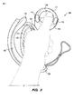
図1〜図4は、本開示の例示的な実施形態にかかる電子システム用のコントローラ100を示している。コントローラ100は、VRビデオゲームシステム、ロボット、武器、または医療機器などの電子システムによって利用されることができる。コントローラ100は、ハンドル112、およびユーザの手(例えば、ユーザの左手)にコントローラ100を保持するためのハンドリテーナ120を有するコントローラ本体110を含むことができる。ハンドル112は、必要に応じて実質的に円筒形とすることができる管状ハウジングを備える。この文脈において、実質的に円筒形の形状は、一定の直径、または完全に円形の断面を有する必要はない。
1 to 4 show a
図1〜図4の実施形態では、コントローラ本体110は、必要に応じて1つ以上の親指操作式コントロール114、115、116を含むことができるヘッド(ハンドル112と遠位端111との間)を含むことができる。例えば、傾斜ボタン、または他のボタン、ノブ、ホイール、ジョイスティック、またはトラックボールは、コントローラ100がユーザの手に保持されている間に、通常の操作中にユーザの親指によって便利に操作されることができる場合、親指操作の制御と見なされることができる。
In the embodiments of FIGS. 1-4, the
コントローラ100は、好ましくは、コントローラ本体110に固定された追跡部材130を含み、必要に応じて、追跡部材130の2つの対向する遠位端のうちの対応する1つからそれぞれ突出する2つのノーズ132、134を含む。図1〜図4の実施形態では、追跡部材130は、好ましくは、必ずしもそうではないが、弓形を有する追跡アークである。追跡部材130は、好ましくは、各突出ノーズ132、134に配置された少なくとも1つの追跡変換器を備える、その中に配置された複数の追跡変換器を含む。追加の追跡変換器は、好ましくは、少なくとも1つの遠位追跡変換器が遠位端111に隣接して配置される、コントローラ本体110にも配置されることができる。
The
前述の追跡変換器は、電子システムによって放出される電磁放射(例えば、赤外線)に応答する追跡センサとすることができるか、あるいは、電子システムによって受信される電磁放射(例えば、赤外線)を放出する追跡ビーコンとすることができる。例えば、電子システムは、ブロードキャストされたパルス赤外光を受信または遮断することができる赤外線センサである追跡部材130の複数の追跡変換器により、パルス赤外線をコントローラ100に向けて広くブロードキャストする、すなわち、ペイントするVRゲームシステムとすることができる。各ノーズ132、134(例えば、各ノーズに3つのセンサ)の追跡変換器は、好ましくは、追跡部材130の各遠位端でユーザの手に張り出し、したがって、(ユーザの手の周りで)よりよく露出されて、許容できない量の遮断なしでより多くの角度で電子システムによって放射される電磁放射を受信するかまたは電子システムに電磁放射を送信する。
The tracking converter described above can be a tracking sensor that responds to electromagnetic radiation (eg, infrared) emitted by the electronic system, or emits electromagnetic radiation (eg, infrared) received by the electronic system. It can be a tracking beacon. For example, an electronic system broadcasts pulsed infrared light widely to
好ましくは、追跡部材130およびコントローラ本体110は、硬質プラスチックなどの実質的に剛性のある材料でできており、それらが互いに対して検知できるほど並進または回転しないように、一体にしっかりと固定されている。このように、空間内の追跡変換器のコンステレーションの並進および回転の追跡は、好ましくは、追跡変換器の互いに対する動きによって複雑にならない。例えば、図1〜図4に示されるように、追跡部材130は、2つの位置でコントローラ本体110に結合されることによって、コントローラ本体110に固定されることができる。ハンドリテーナ120は、これらの2つの場所に隣接するコントローラ100(コントローラ本体110または追跡部材130のいずれか)に取り付けられて、2つの場所の間のハンドル112の外面に対してユーザの手のひらを付勢することができる。
Preferably, the tracking
特定の実施形態では、追跡部材130およびコントローラ本体110は、一体に組み立てられるのではなく、材料の連続性を有する一体型モノリシック構成要素を含むことができる。例えば、追跡部材130およびコントローラ本体110は、単一の射出成形プロセスステップによって一体に成形されることができ、その結果、追跡部材130およびコントローラ本体110の双方を備える1つの一体型硬質プラスチック構成要素をもたらす。あるいは、追跡部材130およびコントローラ本体110は、最初に別々に製造され、その後、一体に組み立てられてもよい。いずれにせよ、追跡部材130は、コントローラ本体110に固定されていると見なすことができる。
In certain embodiments, the tracking
ハンドリテーナ120は、図1の開位置に示されている。ハンドリテーナ120は、必要に応じて、ユーザがVRゴーグルで視界を遮っているコントローラを把持しているとき、湾曲した弾性部材122によって開位置に付勢されて、ユーザの左手をハンドリテーナ120とコントローラ本体110との間に挿入するのを容易にすることができる。例えば、湾曲した弾性部材122は、必要に応じて、弾性的に曲がる可撓性金属ストリップとすることができるか、または実質的に弾性的に曲がることができるナイロンなどの代替プラスチック材料を含むことができる。湾曲した弾性部材122は、必要に応じて、ユーザの快適さのために、クッションまたは布材料124(例えば、ネオプレンシース)の部分的にまたは完全に内部にあるか、またはそれらによって覆われることができる。あるいは、クッションまたは布材料124は、ユーザの手に面する湾曲した弾性部材122の側面のみに配置(例えば、接着)されることができる。
The
ハンドリテーナ120は、必要に応じて、例えば、ばね付勢チョック128によって締め付けられるドローコード126を含むことによって長さを調整することができる。ドローコード126は、必要に応じて、ストラップとして使用することができる余分な長さを有することができる。シース124は、必要に応じて、ドローコードに取り付けることができる。特定の実施形態では、湾曲した弾性部材122は、締められたドローコード126の張力によって予荷重をかけられることができる。そのような実施形態では、湾曲した弾性部材122が(開位置に付勢するために)ハンドリテーナ120に与える張力は、ドローコード126が締め付けられていないときにハンドリテーナを自動的に開放させる。本開示はまた、クリート、弾性バンド(手を挿入すると一時的に伸び、弾性張力を加えて手の甲を押す)、長さ調節が可能なフックおよびループストラップアタッチメントなど、ハンドリテーナ120の長さを調整するための代替の従来の方法を企図する。
The
ハンドリテーナ120は、ハンドル112と追跡部材130との間に配置され、ユーザの手の甲に接触するように構成されることができる。図2は、ユーザの左手が挿入されているが、コントローラ本体110を把持していない動作中のコントローラ100を示している。図2では、ハンドリテーナ120が閉じられ、手の上で締められて、ハンドル112の外面に対してユーザの手のひらを物理的に付勢する。このようにして、ハンドリテーナ120は、閉じたときに、手がコントローラ本体110を把持していないときでさえも、コントローラ100を手に保持することができる。図3および図4は、ハンドリテーナ120が閉じられ、手がコントローラ本体110を把持し、親指が1つ以上の親指操作コントロール(例えば、トラックパッド116)を操作しているときの動作中のコントローラ100を示している。
The
コントローラ本体110のハンドル112は、好ましくは、その外面の周りに部分的または完全に空間的に分散された近接センサのアレイを含む。アレイは、グリッドを含むことができるが、アレイの近接センサは、必ずしも等しいサイズである必要はなく、それらの間の間隔が必ずしも等しいとは限らない。近接センサのアレイは、好ましくは、ハンドル112の外面へのユーザの指の近接に応答する。例えば、近接センサのアレイは、ハンドル112の外面の下に埋め込まれた複数の静電容量センサとすることができ、その外面は、電気的に絶縁性の材料を含む。このような静電容量センサのアレイとユーザの手の一部との間の静電容量は、それらの間の距離に反比例する。静電容量は、RC発振回路を静電容量センサアレイの要素に接続することによって検出されることができ、回路の時定数(したがって発振の周期と周波数)は、静電容量によって変化することに留意されたい。このようにして、回路は、ハンドル112の外面からのユーザの指の解放を検出することができる。
The
ハンドリテーナ120(例えば、ハンドリテンションストラップ)がしっかりと閉じられるとき、それは、コントローラ100が手から落ちるのを防ぐだけでなく、指の動きをより確実に検知するために、指がハンドル112の近接センサアレイに対して過度に平行移動するのを防ぐのに役立つことができる。電子システムは、解剖学的に可能な指の動きを具体化するアルゴリズムを含むことができ、近接センサアレイからの検知をよりよく使用して、制御されたキャラクタの手の開口、指差し、またはコントローラに対する、または互いに対する指の他の動きをレンダリングする。このように、コントローラ100および/または指のユーザの動きは、VRゲームシステム、防衛システム、医療システム、産業用ロボットまたは機械、または別の装置を制御するのに役立つことができる。VRシステムアプリケーション(例えば、ゲーム、トレーニングなど)では、システムは、追跡変換器の動きに基づいて投擲動作をレンダリングし、コントローラのハンドルの外面からのユーザの指の検知された解放に基づいて投球されたオブジェクトの解放をレンダリングすることができる。
When the hand retainer 120 (eg, the hand retention strap) is closed tightly, it not only prevents the
したがって、(ユーザがコントローラ100を実際に手から離したり、床に投げたり落としたりせずに、コントローラ100を「手放す」ことを可能にするための)ハンドリテーナ120の機能は、制御される電子システムの追加機能を有効にすることができる。例えば、コントローラ本体110のハンドル112のユーザの把持の解放および回復が検知された場合、そのような解放または把持は、(例えば、VRにおいて)投げるまたは把持するオブジェクトを表示するためにゲームに組み込まれることができる。ハンドリテーナ120は、そのような機能が繰り返し且つ安全に達成されることを可能にすることができる。例えば、図1〜図4の実施形態におけるハンドリテーナ120の位置は、例えば、ユーザがVR環境で検知されたプロンプトに応答して移動するとき(例えば、VRゴーグルによって実質的に盲目である間)、実世界での衝撃からユーザの手の甲を保護するのに追跡部材130を助けることができる。
Thus, the function of the hand retainer 120 (to allow the user to "release" the
特定の実施形態では、コントローラ100は、コントローラ本体110内に配置された充電式電池を含むことができ、ハンドリテーナ120(例えば、ハンドリテンションストラップ)は、充電式電池に電気的に結合された導電性充電ワイヤを含むことができる。コントローラ100はまた、好ましくは、電子システムの残りの部分と通信するための無線周波数(RF)送信機も含む。そのようなRF送信機は、充電式電池によって電力を供給されることができ、親指操作式コントロール114、115、116、コントローラ本体110のハンドル112内の近接センサ、および/または追跡部材130内の追跡センサに応答することができる。
In certain embodiments, the
図5に示されるように、特定の実施形態では、コントローラ100は、同様の右コントローラ200を含む一対のコントローラ内の左コントローラとすることができる。特定の実施形態では、コントローラ100および200は、例えば、VR体験を強化するために、ユーザの両手の動きおよび把持を(一体に)同時に追跡することができる。
As shown in FIG. 5, in certain embodiments, the
図6Aは、本開示の別の例示的な実施形態にかかる、右手コントローラ600の正面図を示している。図6Bは、右手コントローラ600の背面図を示している。コントローラ600は、ヘッド610およびハンドル612を備えるコントローラ本体を有する。図6A〜図6Bの実施形態では、ヘッド610は、少なくとも1つの親指操作式コントロールA、B、608を含み、人差し指(例えば、トリガー609)によって操作されるように構成された制御も含むことができる。ハンドル612は、外側シェル640によって部分的に包まれた管状ハウジングを備える。
FIG. 6A shows a front view of the
図6A〜図6Bの実施形態では、追跡部材630は、ヘッド610およびハンドル612の端部でコントローラ本体に固定されている。ハンドリテーナ620は、ヘッド610とハンドル612の端部との間の外側シェル640に対してユーザの手のひらを物理的に付勢するように構成される。ハンドリテーナ620は、好ましくは、ハンドル612と追跡部材630との間に配置され、長さが調整可能であり、ユーザの手の甲に接触するように構成されたハンドリテンションストラップを備えることができる。図6A〜図6Bの実施形態では、ハンドリテーナ620は、必要に応じてドローコード628を含み、必要に応じて、コードロック626の場所でドローコード628による滑り運動を選択的に防止するコードロック626(ハンドル612の遠位端に隣接する)によって長さを調整されることができる。
In the embodiments of FIGS. 6A-6B, the tracking
図6A〜図6Bの実施形態では、追跡変換器632、633は、追跡部材630上に配置され、追跡変換器633は、追跡部材630の対向する遠位端の突出したノーズ上に配置される。追加の追跡変換器634は、必要に応じて、ヘッド610の遠位領域に配置される。追跡変換器632、633、および634は、電子システム(例えば、仮想現実ゲームシステム)によって放出される電磁放射(例えば、赤外線)に応答する追跡センサとすることができるか、または電子システムによって受信される電磁放射(例えば、赤外線)を放出する追跡ビーコンとすることができる。例えば、電子システムは、ブロードキャストパルス赤外光を受信することができる赤外線センサである追跡変換器632、633、および634により、コントローラ600に向けてパルス赤外光を広くブロードキャストする、すなわち、ペイントするVRゲームシステムとすることができる。そのような追跡センサの応答は、電子システムに返送されることができ、システムは、そのような応答を解釈して、コントローラ600の位置および向きを効果的に追跡することができる。
In the embodiments of FIGS. 6A-6B, the tracking
追跡変換器632、633、634のうちの1つ以上は、必要に応じて、図7Aの実施形態に示されるように、または代替的に図7Bの実施形態に示されるように、あるいは代替的には示されていない従来の方法で構成されることができる。図7Aの下部は、フレックス回路751に電気的に接続された赤外線センサ750の分解斜視図を示しており、赤外線不透明プラスチックを含む上にあるウィンドウ付きハウジング壁755の長方形部分の下に示されている。ウィンドウ付きハウジング壁755は、ウィンドウ756を含む。ウィンドウ756は、好ましくは、赤外線透過性ポリカーボネートプラスチックを含み、赤外線センサ750の厚さに対応するために下側のくぼみを含むことができる。
One or more of the tracking
図7Aの実施形態によれば、ウィンドウ付きハウジング壁(例えば、追跡部材630の外部構造、または図6Aのヘッド610)は、ハウジング壁の大部分が赤外線不透過性プラスチックで製造されているが、赤外線透過性プラスチックが赤外線センサ750の上のウィンドウ756に配置されるように、いわゆる「ダブルショット」射出成形プロセスから製造されることができる。
According to the embodiment of FIG. 7A, the housing wall with window (eg, the external structure of tracking
図7Aの上部は、組み立てられたときの赤外線センサ750、フレックス回路751、およびウィンドウ付きハウジング壁755の断面図を示している。上からウィンドウ756に入射する3つの下向き矢印として図7Aに示される赤外線は、ウィンドウ756を通過して、下にある赤外線センサ750によって受信される。ハウジング壁755は、赤外線不透過性プラスチックを含むため、それに当たる赤外線は通過せず、一部は、赤外線センサ750によって受信されるためにウィンドウに反射して戻されることができる。このようにして、ウィンドウ756は、ハウジング壁755の大部分が赤外線不透明プラスチックを含むにもかかわらず、赤外線が赤外線センサ750に影響を与えることを可能にし、その結果、赤外線センサ750は、好ましい角度範囲からの赤外線のみを受信する。
The upper part of FIG. 7A shows a cross-sectional view of the
あるいは、追跡変換器632、633、634のうちの1つ以上は、必要に応じて、図7Bの実施形態に示されるように構成されることができる。図7Bの下部は、フレックス回路751に電気的に接続された赤外線センサ750の分解斜視図を示しており、IR透過性プラスチックを含む上にあるハウジング壁758の長方形部分の下に示されている。ハウジング壁758は、ウィンドウ759を含むようにパターン化された赤外線不透明フィルム757でコーティングされている(赤外線不透明フィルム757が存在しない場合)。
Alternatively, one or more of the tracking
図7Bの上部は、組み立てられたときの、赤外線センサ750、フレックス回路751、ハウジング壁758、およびIR不透明フィルム757の断面図を示している。図7Bに上からハウジング壁758に入射する3つの下向き矢印として示される赤外線は、赤外線不透明フィルム757のウィンドウ759を通過してハウジング壁758を通過し、そこで下にある赤外線センサ750によって受信される。ハウジング壁758は、赤外線透過性プラスチックを含むため、それに当たる赤外線は、それを通過して失われる可能性があり、おそらく意図せず、望ましくないことに、内部反射を介して近くのセンサに到達することさえある。このようにして、赤外線不透明フィルム757のウィンドウ759は、赤外線が主に赤外線センサ750に影響を与えることを可能にする。
The upper part of FIG. 7B shows a cross-sectional view of the
図8は、ハンドル612の管状ハウジングを部分的に包む外側シェル640が分解されて、その内面に計装が現れている、右手コントローラ600の側面図を示している。図8の実施形態では、計装は、外側シェル640の内面に空間的に分散された近接センサ800のアレイを含むことができ、近接センサ800のアレイは、ユーザの指の外側シェル640への近接に応答する。アレイの近接センサ800は、必ずしも同じサイズである必要はなく、また、それらは、必ずしも互いに規則的または等間隔に配置されているわけでもない。特定の実施形態では、近接センサ800のアレイは、好ましくは、外側シェル640の内面に結合されたフレックス回路に接続されることができる複数の静電容量センサとすることができる。図8の実施形態では、外側シェル640は、(図9A〜図9Bにより詳細に示されるように)ハンドル612の嵌合する第2の電気コネクタ部分に接続されることができる第1の電気コネクタ部分805を含む。
FIG. 8 shows a side view of the right-
図9A〜Bは、コントローラのハンドルが、必要に応じて、管状ハウジング部分612aおよび612bが隣接するシーム613によって長手方向に分割された管状ハウジング部分612a、612bを備えることができることを示している、図6Aの右手コントローラ600の断面を示している。図9Aでは、外側シェル640は、ハンドルの残りの部分から分解されて離れて示されている。図9Bは、外側シェル640がその通常の動作位置に取り付けられていることを除いて、図9Aの断面を示している。図9A〜図9Bの実施形態では、外側シェル640の第1の電気コネクタ部分805は、コントローラハンドルの第2の電気コネクタ部分905に嵌合し、接続可能であることが示されている。
9A-B show that the handle of the controller can optionally include
図9A〜図9Bの実施形態では、外側シェル640は、管状ハウジング612a、612bを、好ましくは縦方向シーム613と重なるように部分的に包み、その結果、縦方向シーム613は、近接センサアレイ800の所望の円周方向位置に対応するのではなく、製造プロセスを最適化するように配置されることができる。特定の実施形態では、外側シェル640は、ハンドルの管状ハウジング612a、612bの円周部分Cと重なり、円周部分Cは、ハンドルの管状ハウジング612a、612bの全周の少なくとも100度から170度以下の角度にまたがる。そのような円周方向の重なりは、特定の実施形態では、近接センサアレイ800が、ユーザの指または手のひらの所望の部分、例えば、把持を最もよく示す手の領域の近接を検知することを可能にすることができる。
In the embodiments of FIGS. 9A-9B, the
ハンドルの管状ハウジング612a、612bは、円形の断面を有する必要はなく、ハンドルの管状ハウジング612a、612bが円形の断面を有するかどうかにかかわらず、本明細書では「円周」という用語が使用される。本明細書において、「円周」という用語は、ハンドルの管状ハウジング612a、612bの周囲の完全な周囲を意味し、これは、管状ハウジング612a、612bが真円中空柱体である場合には円形とすることができるが、管状ハウジングが非円形の柱体または中空プリズムとして形作られている場合には円以外の閉じた形状とすることができる。
The
図9A〜図9Bの実施形態では、プリント回路基板(PCB)920は、ハンドルの管状ハウジング612a、612b内に取り付けられることができ、第2の電気コネクタ部分905は、PCB920に電気的に結合される。PCB920は、必要に応じて、力検知抵抗器(FSR)922を含み、コントローラは、外側シェル640を介して加えられた圧縮力を、FSR922に対して内向きにハンドルの管状ハウジング612a、612bの外側に向かって伝達するプランジャ924をさらに備えることができる。特定の実施形態では、FSR922は、近接センサアレイ800と併せて、ユーザによる把持の開始、およびユーザによるそのような把持の相対強度の双方の検知を容易にすることができ、これは、特定のゲームプレイ機能を容易にすることができる。
In the embodiments of FIGS. 9A-9B, the printed circuit board (PCB) 920 can be mounted within the
特定の実施形態では、外側シェル640は、ハンドルの管状ハウジング部分612aまたは612bのハウジング壁の厚さの3分の1未満であるシェルの厚さ(図9A〜図9Bで放射状に測定される)を有する。それらの実施形態では、そのような厚さの不均衡は、近接センサアレイ800がハンドルの管状ハウジング612a、612b上または中に配置される代替の実施形態と比較して、近接センサアレイ800の感度を改善することができる。
In certain embodiments, the
図10Aは、部分的に閉じられたハンドリテーナ220(例えば、ハンドリテンションストラップ)を備えた、本開示の別の例示的な実施形態にかかる右手コントローラ200の正面図を示している。図10Bは、ハンドリテーナ220が完全に開いていることを除いて、コントローラ200の正面図を示している。図10A〜図10Bの実施形態では、コントローラ200は、ヘッド210およびハンドル212を有するコントローラ本体を含む。ヘッド210は、コントローラ200のネック領域211でハンドル212に隣接している。ハンドル212は、好ましくは、その外面のすぐ下に空間的に分散され、好ましくは、ハンドル212の外面へのユーザの指の近接に応答する近接センサのアレイを含む。
FIG. 10A shows a front view of a
図10A〜図10Bの実施形態では、ヘッド210は、親指操作式コントロールA、B、および208を含む。コントローラ200はまた、好ましくは、ヘッド210およびハンドル212の遠位端でコントローラ本体に固定される追跡部材230を含む。追跡部材230は、好ましくは、電子システムによって放出される電磁放射(例えば、仮想現実ゲームシステムによって放出されるパルス赤外光)に応答するセンサとすることができる複数の追跡変換器、または電子システムによって受信される電磁放射を放出する追跡ビーコンを含む。図10A〜図10Bの実施形態では、追跡部材230は、好ましくは、必ずしもそうではないが、弓形を有する追跡アークである。ハンドリテーナ220は、好ましくは、ハンドル212と追跡アーク230との間に配置される。
In the embodiments of FIGS. 10A-10B, the
図10A〜図10Bの実施形態では、コントローラ200は、ドローコード228、およびハンドル212の遠位端に隣接するコードロック226を含む。コードロック226は、コードロック226でのドローコード228による滑り運動を選択的に防止することができる。図10Aの実施形態では、ドローコード228がコードロック226を越えて徐々に引っ張られると、ハンドリテーナ220は、閉じた位置に引き締められる(図10Aに示される動きの矢印によって示されるように)。閉位置は、ハンドル212の外面に対してユーザの手のひらを物理的に付勢する。
In the embodiments of FIGS. 10A-10B, the
図10A〜図10Bの実施形態では、ハンドリテーナ220は、好ましくは、ハンドリテーナ220を図10Bに示される開位置に向けて付勢する弾性部材(例えば、金属ストリップなどの内部または外部の弾性変形可能なストリップ)を含む。図10Bの実施形態では、ユーザがコードロック226を選択的に解放させ、ドローコード228の相対的なスライドを可能にするとき、弾性変形弾性部材の真っ直ぐに向けた予荷重付勢により、ハンドリテーナ220が自然に開放する(図10Bに示される動き矢印によって示される)。開位置は、特に仮想現実ゴーグルの着用によってユーザの視界が遮られる可能性がある場合に、コントローラ200からのユーザの手の挿入または引き抜きを容易にすることができる。
In the embodiments of FIGS. 10A-10B, the
図11Aは、ヘッド210の周りを周方向に移動するように調整できるハンドリテーナアンカー302を含む、コントローラ200のヘッド210およびハンドル212の構成要素の正面図を示している。図11Bは、ヘッド210の周囲のハンドリテーナアンカー302の選択的調整を容易にすることができるロック可能なカラー部分311を露出させるためにヘッド210から取り外されたフェースプレートを除いて、同じヘッド210およびハンドル212の構成要素を示している。
FIG. 11A shows a front view of the components of the
図11Bの実施形態では、ロック可能なカラー部分311は、内部弓形ガイド315によって画定される弧状経路に沿って並進することができる。ロック可能なカラー部分311は、ヘッド210の周囲の周りのアンカー302のさらなる動きを防ぐために、ユーザによって選択的にロックされることができる。ここで、図4および図10A〜図11Bを参照すると、ハンドリテーナ220の弾性部材は、ヘッド210のハンドリテーナアンカー302に取り付けられ、これにより、ハンドリテーナ220をユーザの目的に向かってまたは離れて(ユーザの親指と指の間で)調整することができる。特定の実施形態では、ハンドリテーナ220の弾性部材は、好ましくは、回動または回転可能なアタッチメントによってヘッド210のハンドリテーナアンカー302に取り付けられ、その結果、ハンドリテーナ220は、アタッチメントの位置でハンドリテーナアンカー302に対して回動することができる。そのような自由度は、ヘッド210の周囲におけるハンドリテーナアンカー302の位置の調整可能性に追加される。
In the embodiment of FIG. 11B, the
図12A、図12B、および図12Cは、ネック領域411でヘッドに結合されたヘッド410およびハンドル412を含むコントローラ本体を有する部分的に組み立てられたコントローラ400の代替の実施形態を示している。図12A〜図12Cの代替の実施形態では、コントローラ本体は、ネック領域411に隣接して配置されたチャネル414を含む。チャネル414が部分的に覆い隠されないように図12Aに示されていないハンドリテーナは、チャネル414内に延びる突起425で終端する弾性部材420を含む。
12A, 12B, and 12C show alternative embodiments of a partially assembled
図12Bおよび図12Cの実施形態では、突起425は、ハンドリテーナが閉位置にあるときにチャネル414内の突起の長手方向の動きを防止するキャッチ427を含む。例えば、図12Cの実施形態では、キャッチ427は、ハンドリテーナ突起425の相対角度がハンドリテーナの閉位置に対応する場合−すなわち、ハンドリテーナの閉位置が弾性部材420に張力をもたらす場合(例えば、図12Cの断面に示されるように下方向に)、チャネル414の内面との摩擦を増加させるカムである。
In the embodiments of FIGS. 12B and 12C, the
対照的に、ハンドリテーナ突起425が、ハンドリテーナの開位置に対応する相対角度(例えば、図12Cの断面に示されるように上方向)に回転される場合、キャッチ427とチャネル414との間の摩擦は低減され、ハンドリテーナ突起425は、チャネル414内で並進されることができる(図12Bに示される動き矢印によって示されるように)。チャネル414は、好ましくは、例えば、コントローラ400が異なる手のサイズまたは指の長さに対応できるように、チャネル414に沿ったハンドリテーナ突起の並進が、好ましくは、ユーザの手の目的に向かってまたは離れてハンドリテーナ突起425の相対位置を調整するように配向される。代替の実施形態では、ハンドリテーナ突起425は、従来のピボットジョイントによってハンドリテーナの残りの部分に回動可能に取り付けられることができる。このような回転の自由度は、チャネル414に沿ったハンドリテーナ突起425の調整可能な並進に追加される。
In contrast, when the
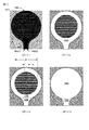
図13A〜Cは、本開示の例示的な実施形態にかかる、力検知抵抗器(FSR)1300の異なる図を示している。図13CのFSR1300の断面図に示されるように、FSR1300は、ポリイミド製の第1の基板1302を含むことができる。FSR1300は、第1の基板1302上(または上)に配置された第2の基板1304をさらに含むことができる。第1の基板1302および第2の基板1304は、FSR1300の2つの主基板(または層)であると見なすことができ、これは、2層FSR1300と見なすことができるが、本明細書でより詳細に説明されるように、FSR1300は、追加層を含むことが理解されるべきである。この文脈において、第1の基板1302は、FSR1300の2つの主基板に関して「下部」または「ベース」基板と見なされることができるが、第1の基板1302の背後(または下方)(すなわち、図13Cに示されるように、負のZ方向)に材料の層があり得ることが理解されるべきである。
13A-C show different views of the force sensing resistor (FSR) 1300 according to an exemplary embodiment of the present disclosure. As shown in the cross-sectional view of the
第1の基板1302は、第1の基板1302の前面(すなわち、正のZ方向に面する表面)に配置された導電性材料を有する。図14を参照してより詳細に説明するように、この導電性材料は、複数の互いに噛み合った金属フィンガを含むことができる。一方、第2の基板1304(抵抗性「膜」と呼ばれることもある)は、第2の基板1304の裏面(すなわち、負のZ方向に面する表面)に抵抗性材料が配置されている。この抵抗性材料は、ある程度の電気抵抗(例えば、平方あたり300キロオーム(kオーム)(kオーム/平方)から400kオーム/平方の範囲内の比較的高いシート抵抗)を示すインク組成物(例えば、銀インク、カーボンインク、それらの混合物など)などの半導体材料とすることができる。好ましくは、第2の基板1304のシート抵抗は、350kオーム/平方であるが、FSR1300が非コントローラベースのアプリケーションなどの他のアプリケーションで使用される場合など、本明細書で指定されたシート抵抗範囲外のものを含む他のシート抵抗値を使用することができることを理解されたい。したがって、本明細書で指定されるシート抵抗範囲は、非限定的であると理解されるべきである。いくつかの実施形態では、第2の基板1304は、抵抗性材料が第2の基板1304の背面に配置されたマイラーでできていてもよい。いくつかの実施形態では、第2の基板1304は、裏面に抵抗性材料(例えば、導電性インク組成物)を有するポリイミドでできている。第2の基板1304にポリイミドを使用することの例示的な利点は、リフローオーブンを使用して大量生産できるFSR1300を作成することであるが、マイラーはそのような高温に耐えることができなかった。
The
FSR1300は、第1の基板1302と第2の基板1304との間に挿入された1つ以上のスペーサ層を含むことができ、その結果、第2の基板1304の中心部分は、第1の基板1302上に懸架され、そこから一定の距離を置いて配置される。図13Cは、これに限定されるものではないが、第1の基板1302の周辺の第1の基板1302上に配置されたカバーレイ1306と、カバーレイ1306上に配置された接着剤層1308とを含む2つのスペーサ層を示している。カバーレイ1306は、ポリイミドでできていてもよく、したがって、第1の基板1302と同じ材料であってもよい。カバーレイ1306の厚さ(Z方向で測定される)は、10ミクロンから15ミクロンの範囲内とすることができる。接着剤層1308の厚さ(Z方向で測定される)は、50ミクロンから130ミクロンの範囲内とすることができる。したがって、第2の基板1304が第1の基板1302から離間する総距離は、1つ以上のスペーサ層の厚さ(例えば、カバーレイ1306の厚さ+接着剤1308の層の厚さ)の合計とすることができる。これらの層は、FSR1300が非コントローラベースのアプリケーションなどの他のアプリケーションで使用される場合など、ここで指定された厚さの範囲外の厚さで提供されることができる。したがって、これらの厚さの範囲は、非限定的であると理解されるべきである。
The
アクチュエータ1310(ディスク形状のコンプライアントプランジャなど)は、第2の基板1304上に配置されることができ、力Fを第2の基板1304の前面に伝達するように構成されている。アクチュエータ1310は、アクチュエータ1310に力を加えるとある程度変形するコンプライアント材料であるポロンで作ることができる。アクチュエータ1310は、加えられた力Fを中心に置くために、FSR1300の活性領域の中心と同心とすることができる。アクチュエータ1310はまた、FSR1300の活性領域のその部分にわたって、加えられた力Fを均等に分配するために、FSR1300の活性領域の一部にまたがる。
The actuator 1310 (such as a disk-shaped compliant plunger) can be placed on the
第2の基板1304の厚さ(Z方向で測定)は、50ミクロンから130ミクロンの範囲内とすることができる。この例示的な厚さでは、第2の基板1304は可撓性である。例えば、第2の基板1304は、上記で指定された範囲内の厚さで可撓性であるマイラーで作ることができる。FSR1300の機能的動作は、第2の基板1304の裏面の抵抗性材料が、アクチュエータ1310に加えられる圧縮力F下で第1の基板1302の前面の導電性材料と接触するために、第2の基板1304の可撓性に依存する。第1の基板1302の厚さ(Z方向で測定)は、20ミクロンから30ミクロンの範囲内とすることができる。この厚さのポリイミドも可撓性がある。したがって、第1の基板1302もまた可撓性である。一方、アクチュエータ1310の厚さ(Z方向で測定)は、780ミクロンから810ミクロンの範囲内とすることができる。これらの層は、FSR1300が非コントローラベースのアプリケーションなどの他のアプリケーションで使用される場合など、ここで指定された厚さの範囲外の厚さで提供されてもよい。したがって、これらの厚さの範囲は、非限定的であると理解されるべきである。
The thickness of the second substrate 1304 (measured in the Z direction) can be in the range of 50 microns to 130 microns. At this exemplary thickness, the
FSR1300は、アクチュエータ1310に加えられる可変力Fに応答して変化する抵抗を示すことができる。例えば、アクチュエータ1310にかかる力Fが増加するにつれて、抵抗は減少する。このようにして、FSR1300は、加えられた力Fによって値が制御される可変抵抗器として扱うことができる。FSR1300は、「シャントモード」FSR1300または「スルーモード」FSR1300とすることができるが、好ましくはシャントモードFSR1300である。シャントモードFSR1300では、第1の基板1302の前面に配置された導電性材料は、複数の互いに噛み合った金属フィンガの形態とすることができる。力Fがアクチュエータ1310の前面(または上部)に加えられると、第2の基板1304の裏面の抵抗性材料が、金属フィンガを分路する噛み合った金属フィンガのいくつかと接触し、それにより、FSR1300の出力端子間の抵抗を変化させる。スルーモードの実装では、第1の基板1302上の導電性材料は、導電性材料上に配置された半導電性(または抵抗性)材料を備えた導電性材料の固体領域とすることができ、第2の基板1304は、同様の構造(例えば、固体半導電性(または抵抗性)材料が配置された導電性材料の領域)を有することができる。各基板(1302および1304)上の導電性材料の固体領域は、個々の出力端子に結合され、2つの基板(1302および1304)が加えられた力Fの下で接触すると、励起電流が1つの層から別の層に流れることができる。
The FSR1300 can exhibit a resistance that changes in response to a variable force F applied to the
少なくとも推奨されるシャントモードの実装では、力と抵抗の応答曲線(FSR1300の抵抗が加えられた力Fの関数としてプロットされる)は、VRシステムのコントローラ100/600で使用するのに望ましい特性を示す。例えば、FSR1300の応答曲線は、下部基板の材料としてマイラーを使用するものなどの従来のFSRと比較して、より少ないヒステリシスおよびより高い再現性(あるFSR1300から別のFSR1300へ)を示すことができる。負荷ヒステリシスは、現在のFSR1300抵抗に対する以前に加えられた力の影響を表す。応答曲線も単調であり、仮想岩を粉砕したり、仮想バルーンを絞ったりするなど、VRゲームシステムの多くのゲーム機構に活用できる真のアナログ入力をモデル化する。本明細書の例は、加えられた力Fを説明しているが、FSR1300は、実際には、第2の基板1304の前面のより大きな領域に対する小さな点において加えられる等しい量の力がFSR1300の異なる抵抗応答をもたらすことから、加えられた圧力(力×面積)に敏感である。したがって、アクチュエータ1310は、加えられた力Fの下での応答曲線に関して、FSR1300全体の再現性を維持する役割を果たしている。
At least in the recommended shunt mode implementation, the force and resistance response curves (plotd as a function of the force F with the resistance of the FSR1300) provide the desired characteristics for use with the
図14は、FSR1300を構築する例示的なプロセスにおける進行ステージでのFSR1300の様々な正面図を示している。図14のステージ1では、ポリイミドの第1の基板1302の前面に複数の噛み合った金属フィンガ1400を形成することができる。金属フィンガ1400は導電性である。金属フィンガ1400に使用される例示的な導電性金属は、1/3オンスHA銅などの銅である。この銅はまた、金めっきされることもできる。複数の互いに噛み合った金属フィンガ1400は、サブトラクティブ製造プロセスを使用して形成することができる。例えば、ステージ1の前に、ポリイミドの第1の基板1302は、その前面に配置された銅クラッド層で形成されることができ、銅クラッド層は、図14のステージ1に示されている互いに噛み合った金属フィンガ1400のパターンを作成するためにエッチングされることができる(例えば、銅材料のストリップを除去することによって)。エッチングされたパターンのサイズと間隔は、0.2ミリメートル(mm)である隣接する金属フィンガ1400の対の間の距離(Y方向で測定)、および0.2mmである複数の互いに噛み合った金属フィンガ1400の各金属フィンガの幅(Y方向で測定)を作成するために選択されることができる。このフィンガ幅とフィンガ間の間隔は、FSR1300の最大感度と最小化された製造エッチング耐性との間の最適なバランスを提供することができる。金属フィンガ1400の均一なパターンが図14に示されているが、他の不均一なパターン(例えば、中心に向かってより密度の高いフィンガ、および外側に向かってより密度の低いフィンガ)を使用できることを理解されたい。図14は、それぞれが第1の出力端子1402(1)および第2の出力端子1402(2)を有する2端子FSR1300の出力端子1402(またはリード)につながる2組の互いに噛み合った金属フィンガ1400を示している。
FIG. 14 shows various front views of the FSR1300 at the progress stage in an exemplary process of constructing the FSR1300. In
前述のように、金属フィンガ1400を構成する銅は、金めっきされることができる。したがって、互いに噛み合った金属フィンガ1400のパターンをエッチングした後、金めっきの層を銅フィンガ上に堆積させて、金めっきされたフィンガを作成することができる。したがって、図14のステージ1に示される複数の互いに噛み合った金属フィンガ1400は、金めっきされたフィンガを表すことができる。金めっきは、無電解ニッケル浸漬金(ENIG)とすることができる。特に、金めっきの前にベース層の銅の上に追加の銅めっきがなくてもよい。多層フレックス基板にビアを追加する場合、通常、ベース層の銅の上に追加の銅めっきが適用される。しかしながら、金めっきの前にベース層の銅に追加の銅めっきを追加すると、金めっきの前にベース層の銅に追加の銅めっきが含まれていない開示されたFSR1300と比較して、検出された抵抗の望ましくない増加が実際に発生する可能性がある。したがって、金めっきの前に金属フィンガ1400上の追加の銅めっきを省略することにより、FSR1300において最適な感度が達成される。したがって、金属フィンガ1400を構成する銅クラッド層は、金属フィンガ1400が金材料でめっきされた時点で露出されたままである。このようにして、金材料は、ベース層銅と金めっきとの間に追加の銅めっきを挿入することなく、金属フィンガ1400のベース銅材料と直接接触している。
As described above, the copper constituting the
図14のステージ2では、カバーレイ1306を、第1の基板1302の周辺の第1の基板1302の上に堆積させることができる。例えば、カバーレイ1306は、金属フィンガ1400の周辺部分を覆うように環状の形状とすることができ、金属フィンガ1400の残りの部分は、堆積後、カバーレイ1306によって覆われないままにされる。カバーレイ1306は、ポリイミドでできていてもよい。
In
図14のステージ3では、接着剤層1308がカバーレイ1306の上に堆積されることができ、その結果、金属フィンガ1400の残りの部分(カバーレイ1306によって覆われずに残された金属フィンガ1400の部分)もまた、接着剤層1308によって覆われずに残される。例えば、接着剤層1308は、接着剤層1308がカバーレイ1306の実質的な部分を覆い、接着剤層1308がFSR1300の活性領域を覆わないように、C字形とすることができる。FSR1300の「活性領域」は、直径Bを有するものとして図14のステージ3に示されている。さらにまた、C字形である接着剤層1308は、カバーレイ1306の部分を接着剤層1308によって覆われないままにすることができる。カバーレイ1306のこの覆われていない部分は、幅wを有するものとして図14のステージ3に示されている。第2の基板1304が第1の基板1302の上部に配置された後、カバーレイ1306のこの覆われていない部分は、空気が第1の基板1302と第2の基板1304との間の空間から出入りすることを可能にするエアギャップを形成し、これは、大気圧の変化によるセンサ間の応答の変動を防ぐことができる。エアギャップ(すなわち、カバーレイ1306の覆われていない部分)の幅wは、1mmとすることができ、これは、加えられた力の下で接触表面積の対称性を維持するのに十分小さく、空気がエアギャップから入る/出るのに十分大きい。いくつかの実施形態では、接着剤層1308は、ミネソタ州メープルウッドの3M(登録商標)社からの467接着剤(すなわち、3M 467接着剤)とすることができる。カバーレイ1306および接着剤層1308は、第2の基板1304を第1の基板1304から懸架的に離間させるために第1の基板1302の上に提供できるスペーサ層の例を表す。前述のように、カバーレイ1306の厚さ(Z方向で測定)は、10ミクロンから15ミクロンの範囲内とすることができ、接着剤層1308の厚さ(Z方向で測定)は、50ミクロンから130ミクロンの範囲内とすることができる。好ましくは、接着剤層1308の厚さは、非常に軽い加えられた力Fの下で初期応答(例えば、FSR1300が入力の検出を開始する)を可能にするために(例えば、指定された厚さ範囲の下端で)可能な限り薄くされる。しかしながら、これらの層は、FSR1300が非コントローラベースのアプリケーションなどの他のアプリケーションで使用される場合など、ここで指定された厚さの範囲外の厚さで提供されてもよい。したがって、これらの厚さの範囲は、非限定的であると理解されるべきである。
In
ステージ4では、第2の基板1304を第1の基板1302の上に設けることができる。ステージ4では、第2の基板1304の中央部分は、第1の基板1302と第2の基板1304との間に挿入された1つ以上のスペーサ層(例えば、カバーレイ1306および接着剤層1308)によって第1の基板1302上に懸架される(図13Cを参照)。図14には示されていないが、アクチュエータ1310は、図13A〜Cに示されるように、FSR1300の構築を完了するために、第2の基板1304の前面に取り付けられることができる。アクチュエータのサイズ(X−Y平面で測定)は、FSR1300の活性領域の80%(すなわち、図14のステージ3に示されている直径Bの80%)に及ぶことができる。例えば、ディスク状のアクチュエータ1310は、0.8*Bに等しい直径を有することができる。いくつかの実施形態では、FSR1300の全体の直径は、14.5mmとすることができる。この寸法では、活性領域は、10.5mmの直径Bを有することができ、これは、カバーレイ1306および接着剤層1308が、第1の基板1302と第2の基板1304との間に2mmのリングとして堆積されることができることを意味する。この実施形態では、アクチュエータ1310は、8.4mm(すなわち、0.8*10.5mm)の直径を有することができる。
In stage 4, the
FSR1300は、外力(または負荷)がない状態で開回路にすることができる。いくつかの実施形態では、ゼロまたは無視できる印加力の下での第1の基板1302と第2の基板1304との任意の接触を説明するために、閾値回路を使用して、第1の基板1302および第2の基板1304が「接触している」と見なされる閾値抵抗値を設定することができ、これは、2つの主基板(すなわち、1302および1304)が実際に接触している場合であっても、閾値抵抗値に到達するまでFSR1300を開回路にすることができることを意味する。
The FSR1300 can be open circuit in the absence of external force (or load). In some embodiments, a threshold circuit is used to illustrate any contact between the
図15は、本開示の別の実施形態にかかる、FSR1300の例示的な層を示している。図15は、縮尺どおりではない。むしろ、図15は、材料の例示的な層を説明するために提示されており、FSR1300の実際の断面図を表すことを意図するものではない。前の図を参照して上述したように、FSR1300は、図15に示されるように、ポリイミドで作られた第1の基板1302と、第1の基板1302の前面に配置された金属フィンガ1400(すなわち、導電性材料)と、第1の基板1302と第2の基板1304との間に1つ以上のスペーサ層が挿入された、第1の基板1302上に配置された第2の基板1304とを含む。この場合、前述のカバーレイ1306および接着剤の層1308を含む、2つの主基板の間に配置された複数のスペーサ層が存在する。アクチュエータ1310もまた、第2の基板1304上に配置されている。
FIG. 15 shows an exemplary layer of FSR1300 according to another embodiment of the present disclosure. FIG. 15 is not on scale. Rather, FIG. 15 is presented to illustrate exemplary layers of material and is not intended to represent an actual cross-sectional view of the
図15の実施形態では、アクチュエータ1310は、ポロンでできていてもよく、794ミクロンの厚さ(Z方向で測定した場合)を有していてもよい。アクチュエータ接着剤層1500を使用して、アクチュエータ1310を第2の基板1304に取り付けることができる。このアクチュエータ接着剤1500は、厚さが70ミクロン(Z方向で測定)とすることができる。アクチュエータ接着剤1500に適した接着剤は、カリフォルニア州グレンデールのエイブリィ・デニソンからのFT 8397接着剤である。図15の実施形態では、第2の基板1304の厚さ(Z方向で測定される)は、125ミクロンとすることができる。第2の基板1304の裏面上の抵抗性材料のシート抵抗は、350kオーム/平方とすることができる。接着剤層1308は、3M MP467接着剤などの剥離接着剤とすることができる。接着剤層1308の厚さ(Z方向で測定される)は、50ミクロンとすることができる。カバーレイ1306は、ポリイミドでできていてもよく、(Z方向で測定して)12.5ミクロンの厚さを有していてもよい。カバーレイ接着剤1502(例えば、いずれかの側に接着剤を有するポリエチレン)を使用して、カバーレイ1306を、金属フィンガ1400の上の第1の基板1302の前面に取り付けることができる。カバーレイ接着剤1502は、25ミクロンの厚さ(Z方向で測定される)を有することができる。金属フィンガ1400は、銅(例えば、金めっきされた銅)でできていてもよく、(Z方向で測定して)12.5ミクロンの厚さを有していてもよい。第1の基板1302は、25ミクロンの厚さ(Z方向で測定される)を有することができる。
In the embodiment of FIG. 15, the
感圧接着剤(PSA)1504は、第1の基板1302の裏面に取り付けられることができる。PSA1504は、3M 467MPとすることができ、50ミクロンの厚さを有することができる。PSAライナ1506は、PSA1504上に配置されることができ、FSR1300を平面(例えば、コントローラ本体110の内部に取り付けられた構造の平面)に取り付ける前に剥がすことができる。
The pressure sensitive adhesive (PSA) 1504 can be attached to the back surface of the
FSR1300のコネクタ部分において、補強材ポリイミド1508は、補強材接着剤1510を使用して、第1の基板1302の裏面に取り付けられることができる。補強材ポリイミド1508は、137.5ミクロンの厚さ(Z方向で測定)を有することができ、コネクタ部分の追加の耐久性のためにFSR1300のより剛性の高いコネクタ部分を作成することができる。補強材接着剤の厚さ(Z方向で測定)は、25ミクロンとすることができる。
In the connector portion of the
図15の実施形態は、本明細書に開示されるように、電子システム(例えば、VRシステム)用のコントローラ100/600のハンドル112/612内に取り付けられる構造の平面に取り付けるのに適したFSR1300を表すことができる。FSR1300が非コントローラベースのアプリケーションなどの他のアプリケーションで使用される場合など、図15を参照して指定されたもの以外の厚さ値、シート抵抗値、および/または材料を利用できることを理解されたい。そのため、これらの値および材料は、非限定的であると理解されるべきである。
The 15th embodiment, as disclosed herein, is an FSR1300 suitable for mounting on a flat surface of a structure mounted within
図16は、本開示の別の実施形態にかかる、FSR1300の例示的な層を示している。図16は、縮尺どおりではない。むしろ、図16は、材料の例示的な層を説明するために提示されており、FSR1300の実際の断面図を表すことを意図するものではない。第1の基板1302および第1の基板1302上の層(すなわち、正のZ方向)に関して図16に示されるFSR1300は、図15に示されるFSR1300と同様の構造を有することができる。図16は、第1の基板1302の下の層(すなわち、負のZ方向)において図15とは異なる。したがって、簡潔にするために、図16のこれらの層については図15の説明を参照することができるので、図16の第1の基板1302および第1の基板1302上の層(すなわち、正のZ方向)は、再び説明されない。
FIG. 16 shows an exemplary layer of FSR1300 according to another embodiment of the present disclosure. FIG. 16 is not on scale. Rather, FIG. 16 is presented to illustrate exemplary layers of material and is not intended to represent an actual cross-sectional view of the
図16の実施形態では、補強材1600は、補強材接着剤1510を使用して、FSR1300の本体部分の下の第1の基板1302の背面に取り付けられることができる。図15の実施形態の場合のように、補強材接着剤の厚さ(Z方向で測定)は25ミクロンとすることができるが、補強材1600は、FSR1300の本体部分の下に配置され、一方、ポリイミド1508は、FSR1300のコネクタ部分の下に配置されている。さらにまた、補強材1600は、図15の実施形態の補強材ポリイミド1508よりも厚い530ミクロンの厚さ(Z方向で測定される)を有するFR4補強材とすることができる。プルタブ1602は、接着剤層1604を使用して補強材1600の背面に取り付けられることができる。接着剤層1604は、3M MP467接着剤などのプルタブ接着剤とすることができる。接着剤層1604の厚さ(Z方向で測定される)は、50ミクロンとすることができる。
In the embodiment of FIG. 16, the reinforcing material 1600 can be attached to the back surface of the
図16の実施形態は、本明細書に開示されるように、電子システム(例えば、VRシステム)のためのコントローラ100/600の親指操作式コントロール116の下方に取り付けられた構造の平面に取り付けるのに適したFSR1300を表すことができる。FSR1300が非コントローラベースのアプリケーションなどの他のアプリケーションで使用される場合など、図16を参照して指定されたもの以外の厚さ値、シート抵抗値、および/または材料を利用できることを理解されたい。そのため、これらの値および材料は、非限定的であると理解されるべきである。
The 16th embodiment, as disclosed herein, is mounted on the plane of the structure mounted below the thumb-operated
図17は、本開示の別の実施形態にかかる、FSR1300の例示的な層を示している。図17は、縮尺どおりではない。むしろ、図17は、材料の例示的な層を説明するために提示されており、FSR1300の実際の断面図を表すことを意図するものではない。図17に示されるFSR1300の層のいくつかは、図15に示されるFSR1300と同様の構造を有することができる。しかしながら、図17は、図15とはいくつかの点で異なる。
FIG. 17 shows an exemplary layer of FSR1300 according to another embodiment of the present disclosure. FIG. 17 is not on scale. Rather, FIG. 17 is presented to illustrate exemplary layers of material and is not intended to represent an actual cross-sectional view of the
図17の実施形態では、第2の基板1304の厚さ(Z方向で測定される)は、127ミクロンとすることができる。接着剤層1308は、3M 468MP接着剤などの剥離接着剤とすることができる。リフローオーブンの高温に耐えることができるFSR1300の場合、接着剤層1308は、3M 9085または3M 9082などの剥離接着剤とすることができる。接着剤層1308の厚さ(Z方向で測定される)は、125ミクロンとすることができる。場合によっては、接着剤層1308の厚さは、50ミクロンとすることができる。さらに、金属フィンガ1400は、RA銅でできていてもよい。さらに、導電性材料1700を第1の基板1302の裏面に配置することができる。導電性材料1700は、12.5ミクロンの厚さ(Z方向で測定される)を有するHA銅またはRA銅とすることができる。追加のカバーレイ1702は、導電性材料1700上に堆積されることができる。この追加のカバーレイ1702は、ポリイミドで作ることができ、カバーレイ接着剤1704を使用して導電性材料1700に取り付けられることができる。追加のカバーレイ1702の厚さ(Z方向で測定される)は、12.5ミクロンとすることができ、カバーレイ接着剤1704の厚さ(Z方向で測定される)は、25ミクロンとすることができる。接着剤層1706は、カバーレイ1702上に配置されることができる。接着剤層1706は、60ミクロンの厚さ(Z方向で測定される)の3M 467MP接着剤などの剥離接着剤とすることができる。リフローオーブンの高温に耐えることができるFSR1300の場合、接着剤層1706は、3M 9085または3M 9082などの剥離接着剤とすることができる。
In the embodiment of FIG. 17, the thickness of the second substrate 1304 (measured in the Z direction) can be 127 microns. The
図17の実施形態は、非VRコントローラのコントローラ本体110内に取り付けられた構造の平面に取り付けるのに適したFSR1300を表すことができる。FSR1300が非コントローラベースのアプリケーションなどの他のアプリケーションで使用される場合など、図17を参照して指定されたもの以外の厚さ値、シート抵抗値、および/または材料を利用できることを理解されたい。そのため、これらの値および材料は、非限定的であると理解されるべきである。
The embodiment of FIG. 17 can represent an
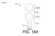
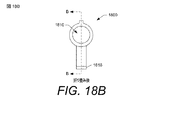
図18A〜Dは、本開示の別の実施形態にかかる、FSR1800を示している。FSR1800は、ポリイミドで作られた第1の基板1802、および可撓性であり、その裏面に抵抗性材料を有する第2の基板1804など、FSR1300に関して説明したものと同様の構成要素層を有することができる。1つ以上のスペーサ層(例えば、カバーレイ1806および接着剤の層1808)を、第1の基板1802と第2の基板1804との間に挿入することができる。
18A-D show the
図18Bおよび図18CのFSR1800の第1の基板1802の一部は、第2の基板1804の周りに巻き付けられ、第2の基板1804の前面にも配置されている。図18Aは、「折り畳み前」とラベル付けされ、第1の基板1802の部分が第2の基板1804の周りに巻き付けられる前のFSR1800を示している。図18Aでは、FSR1800は、第1の本体部分1812(1)(「下部バルーン」1812(1)と呼ばれることもある)および第2の本体部分1812(2)(「上部バルーン1812(2)」と呼ばれることもある)を含む。下部バルーン1812(1)は、下部バルーン1812(1)の第1の端部にある折り畳みネック1814によって上部バルーン1812(2)に接続されている。はんだ付けピグテール1816は、下部バルーン1812(1)の第2の端部から延在し、はんだ付けパッド1818は、はんだ付けピグテール1816の末端にある。タクトスイッチの形態のアクチュエータ1810は、図18Bおよび図18Cに示すように、折り畳み操作後にアクチュエータ1810が最終的にFSR1800の前層または最上層となるように、上部バルーン1812(2)上に配置される。したがって、第2の基板1804の周りに巻き付けられるFSR1800の第1の基板1802の部分は、上部バルーン1812(2)である。
A portion of the
折り畳み操作後のFSR1800の断面がFSR1800の例示的な層を描写するために図18Cに示されている。図18Cに示される層のいくつかは、図18Dを参照してより詳細に説明される。図18Cのこの実施形態では、力Fがアクチュエータ1810(例えば、タクトスイッチ)に加えられ、可変のデジタル化された値に変換されるFSR1800の可変の抵抗を引き起こすことができる。アクチュエータ1810にタクトスイッチ(例えば、事前定義された量の力Fの適用下で異なるバイナリ状態に切り替わるスイッチ)を使用すると、タクトスイッチ1810が作動すると最初に「クリック音がした」後、FSR1800が増加した力Fが加えられると可変抵抗を出力することができる、デュアルステージFSR1800を形成する。これは、タクトスイッチ1810が押されるたびに同じ量の力Fで作動すると仮定することにより、FSR1800の個々の作動でFSR1800を校正するのに役立つことができる。すなわち、FSR1800は、タクトスイッチ1810の作動の検出に応答して、タクトスイッチ1810の作動に関連する既知の量の力Fにリセットすることができる。これは、FSR1800の固有の不正確さを軽減することができる。
A cross section of the FSR1800 after the folding operation is shown in FIG. 18C to depict an exemplary layer of the FSR1800. Some of the layers shown in FIG. 18C will be described in more detail with reference to FIG. 18D. In this embodiment of FIG. 18C, a force F can be applied to the actuator 1810 (eg, a tact switch) to cause a variable resistance of the
図18Cおよび図18Dに示すように、FSR1800は、25ミクロンの厚さ(Z方向で測定される)を有するポリイミドで作られた第1の基板1802を含む。12.5ミクロンの厚さ(Z方向で測定)を有する導電性材料(例えば、図18Dに示されるHA銅(例えば、金めっき銅)で作られた金属フィンガ1820)を、導電性材料が第2の基板1804上の抵抗性材料の下にあるように、下部バルーン1812(1)にある第1の基板1802の前面に配置することができる。カバーレイ接着剤1822を使用して、カバーレイ1806を、金属フィンガ1820の上の第1の基板1802の前面に取り付けることができる。カバーレイ接着剤1822は、25ミクロンの厚さ(Z方向で測定される)を有することができる。カバーレイ1806は、ポリイミドでできていてもよく、(Z方向で測定して)12.5ミクロンの厚さを有していてもよい。カバーレイ1806上に配置された接着剤層1808は、3M MP467接着剤などの剥離接着剤とすることができる。接着剤層1808の厚さ(Z方向で測定される)は、60ミクロンとすることができる。第2の基板1804の厚さ(Z方向で測定される)は、127ミクロンとすることができる。第2の基板1804の裏面上の抵抗性材料のシート抵抗は、350kオーム/平方とすることができる。接着剤層1824を使用して、上部バルーン1812(2)が折り畳みネック1814において下部バルーン1812(1)上に折り畳まれるときに、上部バルーン1812(2)を下部バルーン1812(1)に取り付けることができる。接着剤層1824は、(Z方向で測定して)125ミクロンの厚さとすることができる。接着剤層1824に適した接着剤は、3M 468MPである。接着剤層1824はまた、C字形とすることができる。
As shown in FIGS. 18C and 18D, FSR1800 includes a
FSR1800の上部バルーン1812(2)上で、第1の補強材ポリイミド1834は、補強材接着剤1836を使用して(折り畳む前に)第1の基板1802の前面に取り付けられることができる。第1の補強材ポリイミド1834は、75ミクロンの厚さ(Z方向で測定される)を有することができる。補強材接着剤の厚さ(Z方向で測定)は、25ミクロンとすることができる。さらに、FSR1800の上部バルーン1812(2)上で、接着剤1840の層を使用して、第2の補強材ポリイミド1838を(折り畳む前に)第1の補強材ポリイミド1834の前面に取り付けることができる。第2の補強材ポリイミド1838は、75ミクロンの厚さ(Z方向で測定される)を有することができる。接着剤の層の厚さ(Z方向で測定される)は、125ミクロンとすることができる。上部バルーン1812(2)が折り畳みネック1814において下部バルーン1812(1)上に折り畳まれるとき、第2の補強材ポリイミド1838は、図18Cに示されるように、第2の基板1804と接触し、接着剤層1824は、折り畳み操作後、FSR1800の2つの本体部分1812(1)および1812(2)を積み重ねられた関係で接着する。FSR1800が非コントローラベースのアプリケーションなどの他のアプリケーションで使用される場合など、図18Dを参照して指定されたもの以外の厚さ値、シート抵抗値、および/または材料を利用できることを理解されたい。そのため、これらの値および材料は、非限定的であると理解されるべきである。
On the upper balloon 1812 (2) of the
さらに、図18Dに示されるように、導電性材料1826は、第1の基板1802の裏面に配置されることができる。導電性材料1826は、12.5ミクロンの厚さ(Z方向で測定される)を有するHA銅とすることができる。追加のカバーレイ1828は、導電性材料1826上に堆積されることができる。この追加のカバーレイ1828は、ポリイミドで作ることができ、カバーレイ接着剤1830を使用して導電性材料1826に取り付けられることができる。追加のカバーレイ1828の厚さ(Z方向で測定される)は、12.5ミクロンとすることができ、カバーレイ接着剤1830の厚さ(Z方向で測定される)は、25ミクロンとすることができる。追加のカバーレイ1828およびカバーレイ接着剤1830は、はんだ付けピグテール1816、下部バルーン1812(1)、折り畳みネック1814、および上部バルーン1812(2)の一部にまたがり、アクチュエータ1810用のフットプリント(または空間)(図18Dの「ボタンフットプリント」)を残すことができる。接着剤層1832は、追加のカバーレイ1828上に配置されることができる。接着剤層1832は、125ミクロンの厚さ(Z方向で測定される)の3M 468MP接着剤などの剥離接着剤とすることができる。接着剤1832の層は、はんだ付けピグテール1816および下部バルーン1812(1)にまたがることができる。
Further, as shown in FIG. 18D, the conductive material 1826 can be arranged on the back surface of the
FSR1300/1800の例は、ほぼ円形の形状を有するものとして示されているが、FSR1300/1800は、正方形、長方形などの異なる断面形状の層で構築できることが理解されるべきである。FSR1300/1800は、特定の用途に応じて、ここで説明する例よりも全体のサイズを大きくしたり小さくしたりできる。さらに、FSRのアレイは、複数のFSR1300/1800を一体に接続することによって実装できることを理解されたい。このようなアレイでは、FSR材料の層を材料の長いストリップで構成することができる。 Although the FSR1300 / 1800 example is shown as having a nearly circular shape, it should be understood that the FSR1300 / 1800 can be constructed with layers of different cross-sectional shapes such as squares, rectangles and the like. The FSR1300 / 1800 can be made larger or smaller in overall size than the examples described herein, depending on the particular application. Further, it should be understood that an array of FSRs can be implemented by integrally connecting multiple FSRs 1300/1800. In such an array, layers of FSR material can consist of long strips of material.
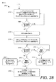
図19は、本明細書に開示されるFSR1300またはFSR1800などのFSRを製造するための例示的なプロセス1900のフロー図である。ここで説明するプロセスは、一連の動作を表す論理フローグラフのブロックの集合として示されている。動作が説明される順序は、限定として解釈されることを意図するものではなく、説明される任意の数の動作は、プロセスを実装するために任意の順序で、および/または並列に組み合わせられることができる。
FIG. 19 is a flow diagram of an
1902において、ポリイミドで作られた第1の基板1302は、第1の基板1302の前面に配置された銅クラッド層で形成されることができる。
In 1902, the
1904において、銅クラッド層をエッチングして第1の基板1302の前面上の複数の互いに噛み合った銅フィンガ(すなわち、金属フィンガ1400の例)を形成することができる。ブロック1904におけるエッチングは、幅0.2mmを有する銅材料のストリップを除去して、複数の互いに噛み合った銅フィンガ間の隣接する銅フィンガの対の間に0.2mmの距離を形成することを含むことができる。除去された銅材料の連続するストリップ間の間隔もまた、0.2mmに保たれて、0.2mmの幅を有する銅フィンガを提供することができる。
In 1904, the copper clad layer can be etched to form a plurality of meshing copper fingers (ie, examples of metal fingers 1400) on the front surface of the
1906において、金めっきの層を複数の交互に配置された銅フィンガに堆積させて、金めっきフィンガを形成することができる。この金めっきは、ENIGとすることができる。 In 1906, gold-plated layers can be deposited on a plurality of alternating copper fingerers to form gold-plated fingers. This gold plating can be ENIG.
1908において、1つ以上のスペーサ層が第1の基板1302の周辺で第1の基板1302の上に提供されることができ、それにより、1つ以上のスペーサ層によって覆われていない金めっきフィンガの一部を残す。サブブロック1910および1912によって示されるように、複数のスペーサ層が2つの動作で提供されることができる。
In 1908, one or more spacer layers can be provided on top of the
1910において、カバーレイ1306(例えば、ポリイミド製)を、第1の基板1302の第1の基板の周辺に堆積させることができる。カバーレイ1306は、金めっきフィンガの周辺部分を覆うことができ、金めっきフィンガの残りの部分は、カバーレイ1306によって覆われないままにされる。
In 1910, a coverlay 1306 (eg, made of polyimide) can be deposited around the first substrate of the
1912において、接着剤層1308をカバーレイ1306に堆積させて、金めっきフィンガの残りの部分が接着剤層1308によって覆われないようにすることができる。さらにまた、ブロック1912における動作は、接着剤層1308によって覆われていないカバーレイ1306の部分を残して、第1の基板1302と第2の基板1304との間の空間から空気が出入りすることを可能にするエアギャップを形成することを含むことができる。
In 1912, the
1914において、第2の基板1304は、第1の基板1302と第2の基板1304との間に挿入された1つ以上のスペーサ層によって、第2の基板1304の中央部分が第1の基板1302上に懸架されるように、第1の基板1302の上に設けられることができる。この第2の基板1304は、可撓性であり、第2の基板1304の裏面に配置された抵抗性材料を有する。
In 1914, the
1916において、FSR1800を構築するために、第1の基板1802の拡張部分が第2の基板1804の周りに巻き付けられ、第2の基板1804の前面に取り付けられ、第1の基板1802の拡張部分は、取り付けられるアクチュエータ1810と第2の基板1804との間に挿入される。ブロック1916の破線の輪郭によって示されるように、この動作は、FSR1800を構築するために実行されるが、FSR1300を構築するときに省略されてもよい。
In 1916, to build the
1918において、アクチュエータ1310は、FSR1300を構築するためにアクチュエータ1310を第2の基板1304の前面に取り付けることによって、またはアクチュエータ1810(例えば、タクトスイッチ)を第1の基板第2の基板1804とアクチュエータ1810との間に挿入された第1の基板1802に取り付けることによって、第2の基板1304の上に設けられることができる。
In 1918, the
本明細書に開示されるFSR1300/1800は、本明細書に開示されるコントローラ100/600などのハンドヘルドコントローラ内の構造の平面に取り付けられることができ、この構造は、コントローラ本体110の外面に加えられる力(例えば、指がコントロールを押すことによって加えられる力、手がハンドル112/612を握ることによって加えられる力)の量に対応する抵抗値を測定するために、コントローラ本体110内の任意の適切な位置に配置されることができる。特に図9Aおよび図9Bを参照すると、FSR1300/1800は、それ自体がハンドル612の管状ハウジング612a、612b内に取り付けられることができる、PCB920の平面に取り付けられることができる。この構成では、プランジャ924は、FSR1300/1800のアクチュエータ1310/1810とインターフェースすることができ、これにより、プランジャ924からアクチュエータ1310/1810に圧縮力を伝達することが可能になることができる。しかしながら、プランジャ924が省略され、アクチュエータ1310/1810がハンドル612の管状ハウジング612a、612bの一部とインターフェースする他の構成が可能である。特に図1を参照すると、FSR1300/1800は、ヘッド(ハンドル112と遠位端111との間)内の構造の平面に取り付けられることができる。ヘッド内に取り付けられた構造は、親指操作式コントロール114、115、116の1つ以上の下方に取り付けられることができる。例えば、FSR1300/1800は、親指操作式コントロール116(例えば、トラックパッド)の下方に配置されることができる。したがって、コントローラ100の動作中にユーザの親指が親指操作式コントロール116を押すと、親指操作式コントロール116の下方に配置されたFSR1300/1800は、ユーザの親指で親指操作式コントロール116に加えられた力の量に対応する抵抗値を測定するように構成されることができる。複数のFSR1300/1800を、ハンドル112/612内に取り付けられた1つ以上のFSR1300/1800、およびコントローラ本体110のヘッド上の1つ以上の対応するコントロール114、115、116の下方に取り付けられた1つ以上のFSR1300/1800など、コントローラのコントローラ本体110内に配置することができることを理解されたい。
The FSR1300 / 1800 disclosed herein can be mounted on the plane of a structure within a handheld controller such as the
本明細書に開示されるFSR1300/1800は、コントローラ100/600に実装されると、可変アナログ入力を可能にすることができる。例えば、ハンドル112/612を握ったり、親指操作式コントロール(例えば、116)を様々な力量で押したりすると、FSR1300/1800の抵抗を加えられた力に応じて変化させることができ、抵抗は、ゲームメカニックを制御するためのFSR入力を表す様々なデジタル化された値に変換されることができる。
The FSR1300 / 1800 disclosed herein can be implemented on the
図20は、電子システムが異なるモードで動作するように、コントローラ100/600などのハンドヘルドコントローラのFSRベースの入力機構を構成するために使用されることができる例示的なユーザインターフェース(UI)2000を示している。UI2000は、ヘッドマウントディスプレイ(HMD)などの電子システムのディスプレイ、またはパーソナルコンピュータ(PC)もしくはゲームコンソールで使用される他のタイプのディスプレイに出力することができる。UI2000は、「アクティベーションタイプ」ドロップダウンメニュー2002を含む。「アクティベーションタイプ」ドロップダウンメニュー2002を使用して、FSRベースの入力機構(例えば、親指操作式コントロール116、ハンドル112/612など)の「ソフトプレス」タイプのアクティベーションを選択することができる。ここで、「ソフトプレス」は、「ソフトウェアプレス」を意味し、これは、コントローラ100/600および/またはコントローラ100/600が関連付けられている電子システムが、FSR1300/1800のアナログ入力(例えば、FSR1300/1800に加えられた力に対応し、デジタル化されたFSR入力値に変換されるFSR抵抗)に基づいて、および後に説明される追加の構成設定にも基づいて、FSRベースの入力イベントを登録するときを、ロジックを使用して判定することを可能にする。換言すれば、抵抗値は、FSR1300/1800によって測定されることができ、これは、デジタル化されたFSR入力値に変換されることができる。このデジタル化されたFSR入力値が「ソフトプレス」の構成設定によって指定された基準を満たしている場合、FSRベースの入力イベントが登録されることができる。
FIG. 20 illustrates an exemplary user interface (UI) 2000 that can be used to configure an FSR-based input mechanism for a handheld controller such as
UI2000は、コントローラ100/600上の対応するFSRベースの入力機構にバインドするためにPCベースの入力コントロールを選択するために使用されることができる「ビンディング」ドロップダウンメニュー2004をさらに含むことができる。ここでは、ビンディングは、マウスの左ボタンとして選択されているが、ビンディングは、他のPCベースの入力コントロールとして選択できることを理解されたい。ビンディングはまた、アナログにすることもできる。例えば、レーシングゲームの場合、アクセルペダルにFSR1300/1800を使用することができる(例えば、ユーザがFSRベースの制御機構を強く押すほど、レーシング車両がゲーム内で速く進む)。
The
UI2000は、ソフトプレスの様々なスタイルのうちの1つを選択するために使用されることができる「ソフトプレススタイル」ドロップダウンメニュー2006をさらに含むことができる。「単純閾値」スタイルは、デジタル化されたFSR入力値が閾値に到達するか超えるとFSR入力イベントが発生することを意味する。デジタル化されたFSR入力値は、FSRによって測定された特定の抵抗値に対応し、FSR1300/1800に加えられた特定の力に対応することから、このスタイルのソフトプレスは、FSRによって測定された抵抗値が抵抗の閾値に到達したとき、および/または加えられた力の量が力の閾値に到達したときのFSR入力イベントの登録として考えることもできる。例えば、コントローラ100/600のハンドル112/612がFSR1300/1800を含む場合、力の閾値量に到達するまでハンドル112/612を握ることができ、それに応じて、FSR入力イベントが「ソフトプレス」として登録される。「押す」のに必要な力は、デバウンスの目的で、および/または物理的なスナップ比でタクトスイッチを模倣するための閾値の一部とすることができる。したがって、「単純閾値」スタイルは、従来の機械式スイッチに取って代わることができる。UI200は、構成可能なソフトプレス閾値2008(1)がユーザによって調整されて、デジタル化されたFSR入力値と比較してFSR入力イベントを登録するかどうかを判定する閾値を増減することができることを示している。ユーザは、FSRベースの入力機構の作動に関連する手の疲労を軽減するために、(例えば、スライダを左に動かすことによって)ソフトプレス閾値2008(1)を低く調整することができる。ユーザは、FSRベースの入力機構によって偶発的な入力が登録されるインスタンスを減らすために、(例えば、スライダを右に移動することによって)ソフトプレス閾値2008(1)をより高く調整することができる。場合によっては、ソフトプレス閾値2008(1)を特定のゲームのデフォルトの閾値に設定することができる(例えば、シューティングゲームのデフォルトの閾値を低くしたり、探索ゲームのデフォルトの閾値を高くしたりする)。
The
「ヘアトリガー」スタイルは、ベースライン閾値を設定することができ、FSR1300/1800に関連付けられたデジタル化されたFSR入力値がベースライン閾値を満たすか超えると、ビンディングがアクティブ化される(すなわち、押し続けるボタンの作動と同様に、FSR入力イベントが登録される)。その後、力が減少すると、ビンディングが非アクティブになり(すなわち、ユーザがボタンを離したのと同じように、FSR入力イベントが「登録解除」される)、ビンディングを非アクティブにした後の力が増加すると、ビンディングが再びアクティブになる。ソフトプレスの「ヘアトリガー」スタイルでは、多少のデバウンスがある場合がある。図21に簡単に目を向けると、「ヘアトリガー」ロジックの例が、力対時間のグラフ2100に示されている。力軸は、ゼロから任意の適切な最大値までの範囲のデジタル化されたFSR入力値を表すことができ、これは、FSR1300/1800によって測定可能な抵抗値の範囲に対応する。図21に示すように、デジタル化されたFSR入力値が増加するにつれて(例えば、ユーザがFSRベースの入力機構をますます強く押す)、デジタル化されたFSR入力値は、最終的にベースライン閾値2102を超え、それに応答して、ビンディングがアクティブ化され(すなわち、FSR入力イベントが長押しタイプのユーザ入力と同様に登録され)、その後、デジタル化されたFSR入力値の減少(例えば、ユーザは、FSRベースの入力機構で僅かに「解放」する)に応答してビンディングが非アクティブ化される。ユーザがFSRベースの入力機構をより強く押すと、力がベースライン閾値2102よりも大きい値に留まっている限り、ビンディングが再びアクティブ化されることができる。
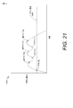
The "hair trigger" style allows you to set a baseline threshold and the binding is activated (ie, when the digitized FSR input value associated with the FSR1300 / 1800 meets or exceeds the baseline threshold). The FSR input event is registered as well as the activation of the button to hold down). Then, when the force decreases, the binding becomes inactive (ie, the FSR input event is "unregistered" as if the user released the button), and the force after deactivating the binding As it increases, the binding becomes active again. There may be some debounce in the soft press "hair trigger" style. A brief look at FIG. 21 shows an example of "hair trigger" logic in
再び図20を参照すると、ソフトプレスの「ヒップファイヤ」スタイルは、3つの異なるサブスタイル(例えば、アグレッシブ、標準、およびリラックス)において選択されることができる。「ヒップファイヤ」スタイルが時間遅延を利用するため、複数レベルのビンディングがある構成では、時間遅延を使用してより高い閾値にすぐに到達した場合に、低いFSR入力値を無視することができることを除き、「ヒップファイヤ」スタイルは、ソフトプレスの「単純閾値」スタイルに似ていることができる。時間遅延量は、サブスタイル(例えば、アグレッシブ、標準、およびリラックス)によって異なる。図22に簡単に目を向けると、「ヒップファイヤ」ロジックの例が、力対時間のグラフ2200に示されている。この場合も、力軸は、ゼロから任意の適切な最大値までのデジタル化されたFSR入力値の範囲を表すことができ、これは、FSR1300/1800によって測定可能な抵抗値の範囲に対応する。図22に示すように、A1 2202が第1のアクションに対応する第1の閾値に対応し、A2 2204が第2のアクションに対応する第2の閾値に対応すると仮定する。時間遅延tは、ヒップファイヤスタイルがアグレッシブタイプ、標準タイプ、またはリラックスタイプのいずれであるかに基づいて設定されることができる。図22に示す「高速」曲線では、FSR入力値は、A1 2202にすばやく到達し、実行を開始するための時間遅延をトリガーする。次に、時間遅延が経過する前にFSR入力値がA2 2204に到達し、これにより、ロジックは、A1 2202を無視し、A2 2204に対応する第2のアクション専用にFSR入力イベントを登録する。図22に示す「遅い」曲線では、FSR入力値がA1 2202に到達し、時間遅延が開始される。しかしながら、時間遅延が経過する前にFSR入力値がA2 2204に到達するほど速く増加しないため、ロジックは、A1 2202に対応する第1のアクションのFSR入力イベントを登録し、その後、FSR入力値は、最終的にA2 2204に到達し、ロジックは、A2 2204に対応する第2のアクションのための追加のFSR入力イベントを登録する。時間遅延tは、ミリ秒単位で指定でき、構成可能である。
With reference to FIG. 20 again, the soft press "hip fire" style can be selected in three different sub-styles (eg, aggressive, standard, and relaxed). Because the "hipfire" style takes advantage of time delays, configurations with multiple levels of bindings can use time delays to ignore low FSR inputs if they reach higher thresholds quickly. Except, the "hipfire" style can be similar to the soft press "simple threshold" style. The amount of time delay depends on the substyle (eg, aggressive, standard, and relaxed). A brief look at FIG. 22 shows an example of "hipfire" logic in the force-to-
再び図20を参照すると、追加のソフトプレス閾値2008(2)が、例えば、ソフトプレスの「ヒップファイヤ」スタイルの閾値などのマルチレベル閾値を設定するために使用可能であり得る。FSRベースの入力用の異なるスタイルのソフトプレスを使用して、ユーザが様々な力でFSRベースの入力機構を握ったり押したりすることで、複数の異なるゲーム関連のアナログ入力を有効にすることができる。例えば、VRゲームは、ユーザが、増加する力でコントローラ本体110のハンドル112/612を圧迫することによって、岩を押しつぶしたり、バルーンを圧迫したりすることを可能にすることができる。別の例として、射撃ベースのゲームは、ユーザが、異なるレベルの加えられた力で親指操作式コントロール116を押すことによって、異なるタイプの武器を切り替えることを可能にすることができる。
With reference to FIG. 20 again, an additional soft press threshold 2008 (2) may be used to set multi-level thresholds, such as, for example, soft press "hipfire" style thresholds. Using different styles of soft press for FSR-based inputs, users can enable multiple different game-related analog inputs by grasping and pushing the FSR-based input mechanism with different forces. can. For example, a VR game can allow a user to squeeze a rock or squeeze a balloon by squeezing the
図23は、コントローラ本体110内に配置された様々なセンサを有する図1のコントローラ100を示している。例えば、第1のFSR1300(1)は、コントローラ本体110のヘッド113に含まれる親指操作式コントロール116などの、押されるように構成されたコントロールの下方に取り付けられることができる。第2のFSR1300(2)は、近接センサ800のアレイとともに、コントローラ本体110のハンドル112内に取り付けられることができる。一方または他方のFSR1300(1)または1300(2)がコントローラ100内に設けられることができるか、またはFSR1300(1)および1300(2)の双方がコントローラ100内に設けられることができることが理解されるべきである。近接センサ800のアレイに加えて、またはその代わりに、1つ以上のタッチセンサ2300(例えば、タッチセンサ2300(1)〜(3))は、親指操作式コントロール114、親指操作式コントロール115、および/または親指操作式コントロール116、および/または指操作式コントロール(例えば、トリガー609)のような、押されるように構成された1つ以上のコントロールに関連付けられることができる。タッチセンサ2300は、関連するコントロール(例えば、親指操作式コントロール114〜116のうちの1つ以上)に接触するオブジェクト(例えば、指、親指など)を示すタッチデータを提供するように構成されることができる。例では、タッチセンサ2300は、コントローラ本体110のヘッド113内に取り付けられた(例えば、外側ハウジングの背面に、およびヘッド113内のPCBなどの構造に取り付けられたコントロール114〜116の下方に接着または他の方法で取り付けられたなど)静電容量センサ(または静電容量センサのアレイ)を備える。他の例では、タッチセンサ2300は、赤外線または音響タッチセンサなどの他のタッチ検知技術に基づくことができる。一方、ハンドル112上に空間的に分散された近接センサ800のアレイは、ハンドル112を握っている手を示す近接データを提供するように構成されることができる。近接センサ800はまた、本明細書に開示されるように、ハンドル112上の/ハンドルへの手の接触および/または近接を検知するための任意の適切な技術を使用することができる。FSR1300は、コントロールの押圧(例えば、コントロール116の押圧)またはハンドル112の圧搾の力量を示す力データを提供するように構成される。図23に示される様々なセンサのセットは、フレックス回路によって接続されることができる。例えば、ヘッド113内のタッチセンサ2300およびFSR1300(1)は、共通のフレックス回路によって一体に接続されることができる。本明細書に開示されるFSR1300のポリイミド基板は、FSR出力端子のフレックス回路へのこのタイプの直接はんだ付けを可能にする。
FIG. 23 shows the
本明細書で説明するプロセスは、ロジックフローグラフ内のブロックの集合として示され、ハードウェア、ソフトウェア、またはそれらの組み合わせで実装できる一連の動作を表す。ソフトウェアの文脈では、ブロックは、1つ以上のプロセッサによって実行されると、列挙された動作を実行するコンピュータ実行可能命令を表す。一般に、コンピュータ実行可能命令は、特定の機能を実行するかまたは特定のデータタイプを実装するルーチン、プログラム、オブジェクト、構成要素、データ構造などを含む。動作が説明される順序は、限定として解釈されることを意図するものではなく、説明される任意の数の動作は、プロセスを実装するために任意の順序で、および/または並列に組み合わせられることができる。 The process described herein is shown as a set of blocks in a logic flow graph and represents a set of operations that can be implemented in hardware, software, or a combination thereof. In the context of software, a block represents a computer executable instruction that, when executed by one or more processors, performs the listed actions. In general, computer executable instructions include routines, programs, objects, components, data structures, etc. that perform a particular function or implement a particular data type. The order in which the actions are described is not intended to be construed as limiting, and any number of actions described may be combined in any order and / or in parallel to implement the process. Can be done.
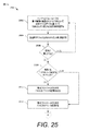
図24は、タッチセンサによって提供されたタッチデータに基づいて、ハンドヘルドコントローラ100/600のFSR1300/1800を再校正するための例示的なプロセス2400のフロー図である。
FIG. 24 is a flow diagram of an
2402において、ハンドヘルドコントローラ100/600のロジックは、タッチセンサによって提供されるタッチデータに少なくとも部分的に基づいて、オブジェクト(例えば、指、親指など)がハンドヘルドコントローラの少なくとも1つのコントロールと接触したことを判定する。少なくとも1つのコントロールは、コントローラ100/600のコントローラ本体110に含まれることができ、押されるように構成されることができる。例えば、コントロールは、コントローラ本体110のヘッド113に含まれる親指操作式コントロール116とすることができる。この実施形態では、タッチセンサは、タッチセンサ2300のうちの1つとすることができる。あるいは、コントロールは、コントローラ本体110のハンドル112とすることができる。この実施形態では、タッチセンサは、近接センサ800のアレイとすることができる。
At 2402, the logic of the
2404において、ロジックは、オブジェクトが少なくとも1つのコントロールと接触したときにFSR1300/1800によって提供された力データに少なくとも部分的に基づいて、FSR1300/1800によって測定された抵抗値を判定することができる。 At 2404, the logic can determine the resistance value measured by the FSR1300 / 1800 based at least in part on the force data provided by the FSR1300 / 1800 when the object contacts at least one control.
2406において、ロジックは、抵抗値をゼロのデジタル化されたFSR入力値と相関させることができる。換言すれば、オブジェクトが少なくとも1つのコントロールに接触したときに検出された抵抗は、ゼロの力入力と見なすことができ、これは、その時点以降にFSR1300/1800に加えられる力の増加が正のFSR入力値と相関することを意味する。したがって、プロセス2400は、−コントロールのタッチの検出の再校正にかかわらず、オブジェクトがコントロールを押していない場合であっても抵抗を測定することができる−FSR1300/1800の固有の不正確さを軽減するのに役立つセンサ融合アルゴリズムを表している。 At 2406, the logic can correlate the resistance value with a digitized FSR input value of zero. In other words, the resistance detected when the object touches at least one control can be considered as a zero force input, which means that the increase in force applied to the FSR1300 / 1800 after that point is positive. It means that it correlates with the FSR input value. Therefore, process 2400-can measure resistance even when the object is not pressing the control-regardless of recalibration of the control's touch detection-reduces the inherent inaccuracy of the FSR1300 / 1800. Represents a sensor fusion algorithm that is useful for.
図25は、隣接する制御のためのタッチセンサによって提供されるタッチデータに基づいて、ハンドヘルドコントローラ100/600のFSR1300/1800における偽入力を無視するための例示的なプロセス2500のフロー図である。
FIG. 25 is a flow diagram of an
2502において、ハンドヘルドコントローラ100/600のロジックは、少なくとも部分的に、ハンドヘルドコントローラの第1のコントロール(例えば、親指操作式コントロール116)に関連するFSR1300/1800によって提供される力データに基づいて、FSR1300/1800によって測定された抵抗値を判定することができる。
At 2502, the logic of the
2504において、ロジックは、抵抗値をデジタル化されたFSR入力値に変換することができる。 At 2504, the logic can convert the resistance value into a digitized FSR input value.
2506において、ロジックは、デジタル化されたFSR入力値が、第1のコントロールのためのFSR入力イベントを登録するために満たされるべき閾値を満たすか、または超えるかどうかを判定することができる。閾値が2506において満たされない場合、プロセス2500は、ブロック2506からブロック2502への「いいえ」ルートをたどって、追加の力データを待つ。閾値が2506において満たされると、プロセス2500は、ブロック2506からブロック2508への「はい」ルートをたどる。
At 2506, the logic can determine whether the digitized FSR input value meets or exceeds the threshold that should be met to register the FSR input event for the first control. If the threshold is not met at 2506,
2508において、ロジックは、第1のコントロール(例えば、親指操作式コントロール114または115)に隣接する第2のコントロールに関連するタッチセンサ2300によって提供されるタッチデータ−FSR抵抗値がFSR1300/1800によって測定されるときに提供されるタッチデータに少なくとも部分的に基づいて、オブジェクト(例えば、指、親指など)が隣接する第2のコントロールと接触しているかどうかを判定することができる。オブジェクトが隣接する第2の制御と接触していない場合、プロセス2500は、ブロック2508からブロック2510への「いいえ」ルートをたどり、ここで、ロジックは、第1のコントロールのFSR入力イベントを登録する(例えば、第1のコントロールのビンディングをアクティブ化することによって)。オブジェクトが隣接する第2のコントロールと接触している場合、プロセス2500は、ブロック2508からブロック2512への「はい」ルートをたどる。
At 2508, the logic measures the touch data-FSR resistance value provided by the
2512において、ロジックは、オブジェクトが第2のコントロールと接触しているとの判定に少なくとも部分的に基づいて、第1のコントロールのFSR入力イベントを登録することを控えることができる。したがって、プロセス2500は、ハンドヘルドコントローラ上の隣接するコントロールの押下に基づいて、FSR1300/1800における偽入力を無視するために使用されることができるセンサ融合アルゴリズムを表す。
At 2512, the logic can refrain from registering the FSR input event for the first control, at least in part, based on the determination that the object is in contact with the second control. Therefore,
図26は、ハンドヘルドコントローラ100/600のハンドル112/612内の近接センサ800のアレイによって検出された手のサイズに基づいてFSR1300/1800のFSR入力閾値を調整するための例示的なプロセス2600のフロー図である。
FIG. 26 shows the flow of an
2602において、ハンドヘルドコントローラ100/600のロジックは、少なくとも部分的に、コントローラ100/600のハンドル上に空間的に分散された近接センサ800のアレイによって提供される近接データに基づいて、ハンドル112/612を把持している手のサイズを判定することができる。手のサイズは、複数の事前定義された手のサイズ(例えば、小と大、または小、中、大など)の中から判定さることができる。
At 2602, the logic of the
2604において、ロジックは、ブロック2602において判定された手のサイズに少なくとも部分的に基づいて、ハンドル112/612のFSR入力イベントを登録するために満たされるべき調整済み閾値に閾値を調整することができる。この調整済み閾値は、ハンドル112/612を握ることができる特定の力の量に対応する。例えば、力の量は、ハンドル112/612内のFSR1300/1800の測定された抵抗に対応し、その抵抗は、デジタル化されたFSR入力値に対応することができる。ユーザがハンドルを握ったときに、デジタル化されたFSR入力値が調整済み閾値以上である場合、FSR入力イベントを登録することができる。したがって、ブロック2602において近接センサ800のアレイによって検出されるように、閾値は、小さい手を有するユーザに対してより低い値に調整されることができる一方で、閾値は、より大きな手を有するユーザに対してより大きな値に調整されることができる。場合によっては、ブロック2602において手のサイズを検出する前に、コントローラ100/600に対してデフォルトの閾値を構成することができ、ブロック2604における調整は、デフォルト値に対して閾値を増減することとすることができる。
At 2604, the logic can adjust the threshold to an adjusted threshold that should be met to register the FSR input event for
図26のサブブロックによって示されるように、プロセス2600は、より詳細な動作を含むことができる。例えば、ブロック2602における手のサイズの判定は、サブブロック2606および2608を含むことができる。
As shown by the subblock of FIG. 26,
2606において、ロジックは、近接データを提供した近接センサ800のアレイの近接センサの数を判定する。例えば、小さな手は、近接センサ800のアレイ内の近接センサの小さなサブセットのみにまたがることができ、小さなサイズの手を検出しない残りの近接センサは、前述の近接データを提供しなくてもよい。対照的に、大きな手は、近接センサ800のアレイ全体にまたがることができ、この場合、近接センサ800の全て(または少なくとも閾値数を超える数)が近接データを提供することができる。
At 2606, the logic determines the number of proximity sensors in the array of
2608において、ロジックは、近接データを提供した(アレイ800の)近接センサの数に少なくとも部分的に基づいて、手のサイズを判定することができる。 At 2608, the logic can determine the size of the hand, at least in part, based on the number of proximity sensors (of the array 800) that provided the proximity data.
さらに、サブブロック2610および2612によって示されるように、ブロック2604での閾値の調整は、コントローラ100/600の1つ以上のFSRの閾値を調整することを含むことができる。
Further, as indicated by sub-blocks 2610 and 2612, adjusting the threshold at
例えば、2610において、ロジックは、コントロール116のFSR入力イベントを登録するために満たされるべき(第1のFSR1300(1)に関連する)第1の閾値を調整することができる。2612において、ロジックは、追加的にまたは代替的に、ハンドル112/612のFSR入力イベントを登録するために満たされるべき第2の閾値(第2のFSR1300(2)に関連する)を調整することができる。
For example, in 2610, logic can adjust a first threshold (related to the first FSR1300 (1)) that should be met to register the FSR input event for
図27は、FSR入力値に基づいてハンドヘルドコントローラの制御のためのビンディングをアクティブ化および非アクティブ化するための例示的なプロセス2700のフロー図である。図27のオフページ参照「A」によって示されるように、プロセス2700は、プロセス2400、2500、または2600のいずれかから継続することができるが、そうする必要はない。
FIG. 27 is a flow diagram of an
2702において、ハンドヘルドコントローラ100/600のロジックは、少なくとも部分的に、コントローラ100/600のFSR1300/1800によって提供される力データに基づいて、最初に、第1のデジタル化されたFSR入力値を判定することができる。この最初にデジタル化されたFSR入力値は、FSR1300/1800によって最初に測定された第1の抵抗値から変換されることができる。
At 2702, the logic of the
2704において、ロジックは、第1のデジタル化されたFSR入力値が、FSR入力イベントを登録するために(例えば、FSR1300/1800に関連するコントロールをバインドするために)満たされるべき閾値を満たすか超えるかを判定することができる。閾値が2704において満たされない場合、プロセス2700は、ブロック2704からブロック2702への「いいえ」ルートをたどり、ロジックは、追加の力データを待つ。2704において閾値に到達した場合、プロセス2700は、ブロック2704からブロック2706への「はい」ルートをたどる。
At 2704, the logic is that the first digitized FSR input value meets or exceeds the threshold that should be met to register the FSR input event (eg, to bind the controls associated with the FSR1300 / 1800). Can be determined. If the threshold is not met at 2704,
2706において、ロジックは、少なくとも部分的に、閾値を満たすかまたはそれを超える第1のデジタル化されたFSR入力値に基づいて、FSR入力イベントを登録することができる(例えば、FSR1300/1800に関連するコントロールに関連するビンディングをアクティブ化するため)。 At 2706, the logic can register FSR input events, at least in part, based on a first digitized FSR input value that meets or exceeds the threshold (eg, related to FSR1300 / 1800). To activate the binding associated with the control you want to do).
2708において、ロジックは、FSR1300/1800によって提供される力データに少なくとも部分的に基づいて、第1の時間の後の第2の時間において、第2のデジタル化されたFSR入力値を判定することができる。この第2のデジタル化されたFSR入力値は、第2の時間にFSR1300/1800によって測定された第2の抵抗値から変換されることができる。
At 2708, the logic determines the second digitized FSR input value in the second time after the first time, at least partially based on the force data provided by the
2710において、ロジックは、第2のデジタル化されたFSR入力値が第1のデジタル化されたFSR入力値よりも小さいかどうか(すなわち、FSR1300/1800による前回の測定以降にFSR入力が減少したかどうか)を判定することができる。第2のデジタル化されたFSR入力値が第1のデジタル化されたFSR入力値よりも小さい場合、プロセス2700は、ブロック2710からブロック2712への「はい」ルートをたどり、ロジックは、(押し続ける入力に相当する、以前に登録されたFSR入力イベントの登録を解除することと考えることができる)FSR1300/1800に関連するコントロールのビンディングを非アクティブ化することができる。第2のデジタル化されたFSR入力値がブロック2710における第1のデジタル化されたFSR入力値以上である場合、プロセス2700は、ブロック2710からブロック2708への「いいえ」ルートをたどり、ロジックは、FSR1300/1800からの追加の力データを待つ。プロセス2700は、図21に示されて上述したFSR検出モードを反映することができる。したがって、ブロック2704において評価された閾値は、図21を参照して説明されたベースライン閾値2102に対応することができる。
At 2710, the logic is whether the second digitized FSR input value is less than the first digitized FSR input value (ie, has the FSR input decreased since the last measurement by FSR1300 / 1800? Please) can be determined. If the second digitized FSR input value is less than the first digitized FSR input value,
図28は、複数の閾値の第1のFSR入力を無視するかどうかを判定するために時間遅延を使用するための例示的なプロセス2800のフロー図である。図28のオフページ参照「A」によって示されるように、プロセス2800は、プロセス2400、2500、または2600のいずれかから継続することができるが、そうする必要はない。
FIG. 28 is a flow diagram of an
2802において、ハンドヘルドコントローラ100/600のロジックは、少なくとも部分的に、コントローラ100/600のFSR1300/1800によって提供される力データに基づいて、最初に、第1のデジタル化されたFSR入力値を判定することができる。この最初にデジタル化されたFSR入力値は、FSR1300/1800によって最初に測定された第1の抵抗値から変換されることができる。
At 2802, the logic of the
2804において、ロジックは、第1のデジタル化されたFSR入力値が第1のFSR入力イベントを登録するために(例えば、FSR1300/1800に関連付けられたコントロールをビンディングするために)満たされるべき第1の閾値(例えば、図22のA1 2202)を満たすか超えるかを判定することができる。第1のFSR入力イベントは、第1のアクション(例えば、第1のゲームメカニック)に関連付けられることができる。第1の閾値が2804において満たされない場合、プロセス2800は、ブロック2804からブロック2802への「いいえ」ルートをたどり、ロジックは、追加の力データを待つ。2804において閾値に到達した場合、プロセス2800は、ブロック2804からブロック2806への「はい」ルートをたどる。
At 2804, the logic is that the first digitized FSR input value should be satisfied to register the first FSR input event (eg, to bind the control associated with the FSR1300 / 1800). (For example,
2806において、ロジックは、事前定義された期間(例えば、図22の時間遅延t)の監視を開始することができる。 At 2806, the logic can start monitoring for a predefined period (eg, time delay t in FIG. 22).
2808において、ロジックは、FSR1300/1800によって提供される力データに少なくとも部分的に基づいて、第1の時間の後の第2の時間において、第2のデジタル化されたFSR入力値を判定することができる。この第2のデジタル化されたFSR入力値は、第2の時間においてFSR1300/1800によって測定された第2の抵抗値から変換されることができる。
At 2808, the logic determines the second digitized FSR input value in the second time after the first time, at least partially based on the force data provided by the
2810において、ロジックは、第2のデジタル化されたFSR入力値が第2のFSR入力イベントを登録するために(例えば、FSR1300/1800に関連付けられたコントロールをビンディングするために)満たされるべき第2の閾値(例えば、図22のA2 2204)を満たすか超えるかを判定することができる。第2のFSR入力イベントは、第1のアクションとは異なる第2のアクション(例えば、第2のゲームメカニック)に関連付けられることができ、第2の閾値は、第1の閾値よりも大きい。第2の閾値が2810において満たされない場合、プロセス2800は、ブロック2810からブロック2812への「いいえ」ルートをたどり、ロジックは、事前定義された期間が経過したかどうか(例えば、第2の時間と第1の時間との差が事前定義された期間よりも短いかどうか)を判定するのを待つ。ブロック2812において期間がまだ経過していない場合、プロセス2800は、ブロック2812からブロック2810に戻る「いいえ」ルートをたどることによって反復する。ブロック2812において期間が経過し、第2の閾値が満たされていない場合、プロセス2800は、ブロック2812からブロック2814への「はい」ルートをたどり、ロジックは、(例えば、第1のアクションまたはゲームメカニックに関連付けられることができる)第1の閾値に対して第1のFSR入力イベントを登録することができる。
At 2810, the logic is that the second digitized FSR input value should be satisfied to register the second FSR input event (eg, to bind the control associated with the FSR1300 / 1800). (For example,
第2の閾値が2810において満たされる場合、プロセス2800は、ブロック2810からブロック2816への「はい」ルートをたどり、ロジックは、事前定義された期間を評価する。)。ブロック2816において期間がまだ経過していない場合、プロセス2800は、ブロック2816からブロック2818に戻る「いいえ」ルートをたどり、ロジックは、第1のFSR入力イベントの登録を控え、(例えば、第2のアクションまたはゲームメカニックに関連付けられることができる)第2の閾値に関連付けられた第2のFSR入力イベントを登録する。ブロック2816において期間が経過し、第2の閾値に到達した場合、プロセス2800は、ブロック2816からブロック2820への「はい」ルートをたどり、ロジックは、第1の閾値の第1のFSR入力イベントと第2の閾値の第2のFSR入力イベントの双方を登録することができる。プロセス2800は、図22に示されて上述したFSR検出モードを反映することができる。
If the second threshold is met at 2810,
図29は、図1のコントローラ100などのハンドヘルドコントローラの例示的な構成要素を示すが、図29に示される構成要素は、コントローラ600によっても実装されることができる。図示のように、ハンドヘルドコントローラは、上述したコントロール(例えば、ジョイスティック、トラックパッド、トリガーなど)、潜在的に他の任意のタイプの入力または出力装置などの1つ以上の入力/出力(I/O)装置2902を含む。例えば、I/O装置2902は、ユーザ音声入力などの音声入力を受信するための1つ以上のマイクロフォンを含むことができる。いくつかの実装では、1つ以上のカメラまたは他のタイプのセンサ(例えば、慣性測定ユニット(IMU))は、ハンドヘルドコントローラ100の動きなどのジェスチャ入力を受信するための入力装置として機能することができる。いくつかの実施形態では、追加の入力装置は、キーボード、キーパッド、マウス、タッチスクリーン、ジョイスティック、コントロールボタンなどの形態で提供されることができる。入力装置は、音量を増減するための基本的な音量制御ボタン、ならびに電源ボタンおよびリセットボタンなどの制御機構をさらに含むことができる。
FIG. 29 shows exemplary components of a handheld controller such as
一方、出力装置は、ディスプレイ、光要素(例えば、LED)、触覚感覚を形成するためのバイブレータ、スピーカ(例えば、ヘッドホン)などを含むことができる。例えば、電源がオンになっているときなどの状態を示すための単純な光要素(例えば、LED)もあり得る。いくつかの例が提供されているが、ハンドヘルドコントローラは、追加的にまたは代替的に、任意の他のタイプの出力装置を含むことができる。 On the other hand, the output device can include a display, an optical element (eg, LED), a vibrator for forming a tactile sensation, a speaker (eg, headphones), and the like. For example, there could be a simple light element (eg, an LED) to indicate a state, such as when the power is on. Although some examples are provided, the handheld controller can additionally or optionally include any other type of output device.
さらに、ハンドヘルドコントローラ100は、ネットワークおよび/または1つ以上のリモートシステム(例えば、アプリケーションを実行するホストコンピューティング装置、ゲームコンソールなど)への無線接続を容易にするための1つ以上の通信インターフェース2904を含むことができる。通信インターフェース2904は、Wi−Fi、ブルートゥース、無線周波数(RF)などのような様々な無線技術のうちの1つ以上を実装することができる。ハンドヘルドコントローラ100は、ネットワーク、接続された周辺機器、または他の無線ネットワークと通信するプラグインネットワーク装置への有線接続を容易にするための物理ポートをさらに含むことができることが理解されるべきである。
In addition, the
図示の実施形態では、ハンドヘルドコントローラは、1つ以上のプロセッサ2906およびコンピュータ可読媒体2908をさらに含む。いくつかの実装では、プロセッサ(複数可)2906は、中央処理装置(CPU)、グラフィック処理装置(GPU)、CPUとGPUの双方、マイクロプロセッサ、デジタルシグナルプロセッサ、または当該技術分野で知られている他の処理装置もしくは構成要素を含むことができる。代替的にまたは追加的に、本明細書で機能的に説明される機能は、少なくとも部分的に、1つ以上のハードウェアロジック構成要素によって実行されることができる。例えば、限定されるものではないが、使用できるハードウェアロジック構成要素の例示的なタイプは、フィールドプログラマブルゲートアレイ(FPGA)、特定用途向け集積回路(ASIC)、特定用途向け標準製品(ASSP)、システム・オン・チップシステム(SOC)、コンプレックスプログラマブルロジック装置(CPLD)などを含む。さらに、各プロセッサ2906は、プログラムモジュール、プログラムデータ、および/または1つ以上のオペレーティングシステムも記憶することができる独自のローカルメモリを有することができる。 In the illustrated embodiment, the handheld controller further comprises one or more processors 2906 and a computer-readable medium 2908. In some implementations, the processor (s) 2906 is known in the art as a central processing unit (CPU), graphics processing unit (GPU), both CPU and GPU, microprocessor, digital signal processor, or the like. Other processing units or components can be included. Alternatively or additionally, the functions described functionally herein can be performed, at least in part, by one or more hardware logic components. For example, but not limited to, exemplary types of hardware logic components that can be used include field programmable gate arrays (FPGAs), application specific integrated circuits (ASICs), application standard products (ASSPs), and more. Includes system-on-chip systems (SOCs), complex programmable logic devices (CPLDs), and more. In addition, each processor 2906 may have its own local memory that can also store program modules, program data, and / or one or more operating systems.
一般に、コントローラは、本明細書に記載の技術、機能、および/または動作を実装するように構成されたロジック(例えば、ソフトウェア、ハードウェア、および/またはファームウェアなど)を含むことができる。コンピュータ可読媒体2908は、コンピュータ可読命令、データ構造、プログラムモジュール、または他のデータなどの情報の記憶のための任意の方法または技術で実装される、揮発性および不揮発性メモリ、取り外し可能媒体および非取り外し可能媒体を含むことができる。そのようなメモリは、これらに限定されるものではないが、RAM、ROM、EEPROM、フラッシュメモリまたはその他のメモリ技術、CD−ROM、デジタル多用途ディスク(DVD)またはその他の光ストレージ、磁気カセット、磁気テープ、磁気ディスクストレージまたはその他の磁気ストレージ装置、RAIDストレージシステム、または所望の情報を記憶するために使用されることができ且つコンピューティング装置からアクセスされることができる任意の他の媒体を含む。コンピュータ可読媒体2908は、コンピュータ可読記憶媒体(「CRSM」)として実装されることができ、これは、コンピュータ可読媒体2908に記憶された命令を実行するためにプロセッサ2906によってアクセス可能な任意の利用可能な物理媒体とすることができる。1つの基本的な実装では、CRSMは、ランダムアクセスメモリ(「RAM」)およびフラッシュメモリを含むことができる。他の実装では、CRSMは、これらに限定されるものではないが、読み取り専用メモリ(「ROM」)、電気的に消去可能なプログラム可能な読み取り専用メモリ(「EEPROM」)、または所望の情報を記憶するために使用されることができ且つプロセッサ2906によってアクセスされることができる任意の他の有形媒体を含むことができる。 In general, a controller can include logic (eg, software, hardware, and / or firmware, etc.) that is configured to implement the techniques, functions, and / or operations described herein. The computer-readable medium 2908 is a volatile and non-volatile memory, removable medium and non-volatile memory implemented by any method or technique for storing information such as computer-readable instructions, data structures, program modules, or other data. Detachable media can be included. Such memories are, but are not limited to, RAM, ROM, EEPROM, flash memory or other memory technologies, CD-ROMs, digital versatile disks (DVDs) or other optical storage, magnetic cassettes, etc. Includes magnetic tape, magnetic disk storage or other magnetic storage devices, EEPROM storage systems, or any other medium that can be used to store desired information and can be accessed from computing devices. .. The computer-readable medium 2908 can be implemented as a computer-readable storage medium (“CRSM”), which is any available available by the processor 2906 to execute instructions stored on the computer-readable medium 2908. Can be a physical medium. In one basic implementation, the CRSM can include random access memory (“RAM”) and flash memory. In other implementations, the CRSM is limited to, but is not limited to, read-only memory (“ROM”), electrically erasable programmable read-only memory (“EEPROM”), or desired information. It can include any other tangible medium that can be used for storage and can be accessed by processor 2906.
命令、データストアなどのようないくつかのモジュールは、コンピュータ可読媒体2908内に記憶され、プロセッサ2906上で実行するように構成されることができる。いくつかの例示的な機能モジュールは、コンピュータ可読媒体2908に記憶され、プロセッサ2906上で実行されるものとして示されているが、同じ機能は、ハードウェア、ファームウェア、またはシステムオンチップ(SOC)として代わりに実装されてもよい。 Some modules, such as instructions, data stores, etc., can be stored on a computer-readable medium 2908 and configured to run on a processor 2906. Some exemplary functional modules are stored on computer-readable media 2908 and shown to run on processor 2906, but the same functionality as hardware, firmware, or system-on-chip (SOC). It may be implemented instead.
オペレーティングシステムモジュール2910は、他のモジュールの利益のために、ハンドヘルドコントローラ100内の且つハンドヘルドコントローラに結合されるハードウェアを管理するように構成されることができる。さらに、コンピュータ可読媒体2908は、ハンドヘルドコントローラ100が、通信インターフェース2904を介して、アプリケーション(例えば、ゲームアプリケーション)を実行するパーソナルコンピューティング装置、ゲームコンソール、HMD、リモートサーバなどの1つ以上の他の装置と通信することを可能にするネットワーク通信モジュール2912を記憶することができる。コンピュータ可読媒体2908は、ハンドヘルドコントローラまたはハンドヘルドコントローラ100が結合するコンピューティング装置上で実行されるゲーム(または他のアプリケーション)に関連するデータを記憶するためのゲームセッションデータベース2914をさらに含むことができる。コンピュータ可読媒体2908はまた、パーソナルコンピューティング装置、ゲームコンソール、HMD、リモートサーバなど、ハンドヘルドコントローラ100が結合する装置に関連するデータを記憶する装置記録データベース2916を含むことができる。コンピュータ可読媒体2908は、ハンドヘルドコントローラ100をゲームコントローラとして機能するように構成するゲーム制御命令2918、およびハンドヘルドコントローラ100を他の非ゲーム装置のコントローラとして機能するように構成するユニバーサル制御命令2920をさらに記憶することができる。
The operating system module 2910 can be configured to manage the hardware within the
特に明記しない限り、明細書および特許請求の範囲で使用される数量を表す全ての数字は、全ての場合において「約」という用語によって変更されるものとして理解されるべきである。したがって、反対に示されない限り、本明細書および添付の特許請求の範囲に記載された数値パラメータは、本開示によって得られることが求められる所望の特性に応じて変化することができる近似値である。少なくとも、均等論の適用を特許請求の範囲に限定する試みとしてではなく、各数値パラメータは、少なくとも報告された有効桁数に照らして、通常の丸め手法を適用することによって解釈されるべきである。さらに明確にする必要がある場合、「約」という用語は、記載された値の±20%、記載された値の±19%、記載された値の±18%、記載された値の±17%、記載された値の±16%、記載された値の±15%、記載された値の±14%、記載された値の±13%、記載された値の±12%、記載された値の±11%、記載された値の±10%、記載された値の±9%、記載された値の±8%、記載された値の±7%、記載された値の±6%、記載された値の±5%、記載された値の±4%、記載された値の±3%、記載された値の±2%、または記載された値の±1%の範囲内まで、記載された数値または範囲と組み合わせて使用される場合、すなわち、記載された値または範囲よりもいくらか多いまたはいくらか少ないことを示すときに当業者によって合理的に帰される意味を有する。 Unless otherwise stated, all numbers representing quantities used in the specification and claims should be understood as being modified by the term "about" in all cases. Thus, unless otherwise indicated, the numerical parameters described herein and in the appended claims are approximations that can vary depending on the desired properties required to be obtained by the present disclosure. .. At least, not as an attempt to limit the application of the doctrine of equivalents to the claims, each numerical parameter should be interpreted by applying conventional rounding techniques, at least in the light of the reported number of significant digits. .. Where more clarification is needed, the term "about" is ± 20% of the stated value, ± 19% of the stated value, ± 18% of the stated value, ± 17 of the stated value. %, ± 16% of the stated value, ± 15% of the stated value, ± 14% of the stated value, ± 13% of the stated value, ± 12% of the stated value, stated. ± 11% of the value, ± 10% of the stated value, ± 9% of the stated value, ± 8% of the stated value, ± 7% of the stated value, ± 6% of the stated value. Within the range of ± 5% of the stated value, ± 4% of the stated value, ± 3% of the stated value, ± 2% of the stated value, or ± 1% of the stated value. , When used in combination with the stated values or ranges, i.e., meaning reasonably attributed by one of ordinary skill in the art when indicating somewhat more or less than the stated values or ranges.
主題について構造的特徴および/または方法論的動作に特有の言語で説明したが、添付の特許請求の範囲に定義された主題は、必ずしも説明された特定の特徴または動作に限定されるものではない。むしろ、特定の特徴および動作は、特許請求の範囲を実装する例示的な形態として開示されている。 Although the subject matter has been described in a language specific to structural features and / or methodological behaviors, the subject matter defined in the appended claims is not necessarily limited to the particular feature or behavior described. Rather, certain features and behaviors are disclosed as exemplary forms that implement the claims.
本開示は、本明細書の特定の例示的な実施形態を参照して説明されるが、当業者は、本開示がそれらに限定されないことを認識するであろう。本開示の様々な特徴および態様は、個別にまたは共同で、場合によっては異なる環境または用途で使用できることが企図されている。例えば、右手コントローラに関して示されている特徴は、左手コントローラにも実装されることができ、その逆も可能である。したがって、明細書および図面は、限定的ではなく、説明的且つ例示的であると見なされるべきである。例えば、「好ましくは」という語、および「好ましくは、しかし必ずしもそうではない」という句は、本明細書では同義語として使用され、「必ずしもではない」または任意選択の意味を一貫して含む。「備える」、「含む」、および「有する」は、制約のない用語であることが意図されている。 The present disclosure will be described with reference to certain exemplary embodiments herein, but those skilled in the art will recognize that the present disclosure is not limited thereto. It is contemplated that the various features and aspects of the present disclosure may be used individually or jointly, and in some cases in different environments or applications. For example, the features shown for a right-hand controller can also be implemented for a left-hand controller and vice versa. Therefore, the specification and drawings should be considered non-limiting, descriptive and exemplary. For example, the word "preferably" and the phrase "preferably but not necessarily" are used herein as synonyms and consistently include the meaning of "not necessarily" or optional. "Prepare," "include," and "have" are intended to be unconstrained terms.
Claims (23)
コントローラ本体と、
前記コントローラ本体内に取り付けられた力検出抵抗器(FSR)とを備え、前記FSRが、
ポリイミド製の第1の基板であって、前記第1の基板の前面に導電性材料が配置されている、第1の基板と、
可撓性がある第2の基板であって、前記第2の基板の裏面に配置された抵抗性材料を有し、前記第1の基板上に配置されている、第2の基板と、
前記第1の基板と前記第2の基板との間に挿入された1つ以上のスペーサ層とを備える、ハンドヘルドコントローラ。 It ’s a handheld controller,
With the controller body
A force detection resistor (FSR) mounted in the controller body is provided, and the FSR is
A first substrate made of polyimide, wherein a conductive material is arranged on the front surface of the first substrate, and a first substrate.
A second substrate that is flexible and has a resistant material disposed on the back surface of the second substrate and is disposed on the first substrate.
A handheld controller comprising one or more spacer layers inserted between the first substrate and the second substrate.
前記コントローラ本体がハンドルを含み、
前記FSRが、前記ハンドル内に取り付けられた構造の平面に取り付けられており、
前記FSRが、前記ハンドルの外面に加えられる力の量に対応する抵抗値を測定するように構成されている、ハンドヘルドコントローラ。 The handheld controller according to claim 1.
The controller body includes a handle
The FSR is mounted on a flat surface of the structure mounted within the handle.
A handheld controller in which the FSR is configured to measure a resistance value corresponding to the amount of force applied to the outer surface of the handle.
前記コントローラ本体が、少なくとも1つの親指操作式コントロールを含み、
前記FSRが、前記少なくとも1つの親指操作式コントロールの下方に取り付けられている構造の平面に取り付けられており、
前記FSRが、前記少なくとも1つの親指操作式コントロールに加えられる力の量に対応する抵抗値を測定するように構成されている、ハンドヘルドコントローラ。 The handheld controller according to claim 1.
The controller body includes at least one thumb-operated control.
The FSR is mounted on a plane of construction that is mounted below the at least one thumb-operated control.
A handheld controller in which the FSR is configured to measure a resistance value corresponding to the amount of force applied to the at least one thumb-operated control.
前記導電性材料が、前記第1の基板の前記前面に配置された複数の互いに噛み合った金属フィンガを含み、
前記複数の互いに噛み合った金属フィンガが、ベース銅材料と、前記ベース銅材料の上に金材料とを含む金めっき銅でできており、
前記金材料が、前記ベース銅材料と直接接触している、ハンドヘルドコントローラ。 The handheld controller according to claim 1.
The conductive material comprises a plurality of meshing metal fingers disposed on the front surface of the first substrate.
The plurality of meshing metal fingers are made of gold-plated copper containing a base copper material and a gold material on top of the base copper material.
A handheld controller in which the gold material is in direct contact with the base copper material.
前記第1の基板の周囲において前記第1の基板上に配置されたポリイミドのカバーレイであって、前記導電性材料の周辺部分を覆い、前記導電性材料の残りの部分が前記カバーレイによって覆われないままにする、カバーレイと、
前記カバーレイ上に配置された接着剤層であって、前記接着剤層によって覆われていない前記導電性材料の前記残りの部分を残し、前記接着剤層によって覆われていない前記カバーレイの部分を残して、空気が前記第1の基板と前記第2の基板との間の空間から入るまたは出ることを可能にするエアギャップを形成する、接着剤層とを含む、請求項1に記載のハンドヘルドコントローラ。 The one or more spacer layers
A polyimide coverlay arranged on the first substrate around the first substrate, which covers a peripheral portion of the conductive material, and the remaining portion of the conductive material is covered by the coverlay. Coverlay and leave it untouched,
A portion of the coverlay that is an adhesive layer disposed on the coverlay, leaving the remaining portion of the conductive material not covered by the adhesive layer and not covered by the adhesive layer. The first aspect of the invention, which comprises an adhesive layer that forms an air gap that allows air to enter or exit the space between the first substrate and the second substrate, leaving the adhesive layer. Handheld controller.
前記カバーレイおよび前記接着剤層によって覆われていない前記導電性材料の前記残りの部分の領域が、前記FSRの活性領域に対応し、
前記アクチュエータが、前記活性領域の80%をカバーし、前記アクチュエータが、前記FSRの前記活性領域の中心と同心である、請求項6に記載のハンドヘルドコントローラ。 Further, an actuator arranged on the second substrate and configured to transmit a force to the front surface of the second substrate is provided.
The remaining region of the conductive material not covered by the coverlay and the adhesive layer corresponds to the active region of the FSR.
The handheld controller of claim 6, wherein the actuator covers 80% of the active region and the actuator is concentric with the center of the active region of the FSR.
ポリイミド製の第1の基板であって、前記第1の基板の前面に導電性材料が配置されている、第1の基板と、
可撓性がある第2の基板であって、前記第2の基板の裏面に配置された抵抗性材料を有し、前記第1の基板上に配置されている、第2の基板と、
前記第1の基板と前記第2の基板との間に挿入された1つ以上のスペーサ層とを備える、力検知抵抗器(FSR)。 It is a force detection resistor (FSR)
A first substrate made of polyimide, wherein a conductive material is arranged on the front surface of the first substrate, and a first substrate.
A second substrate that is flexible and has a resistant material disposed on the back surface of the second substrate and is disposed on the first substrate.
A force sensing resistor (FSR) comprising one or more spacer layers inserted between the first substrate and the second substrate.
前記複数の互いに噛み合った金属フィンガが、ベース銅材料と、前記ベース銅材料の上に金材料とを含む金めっき銅でできており、
前記金材料が、前記ベース銅材料と直接接触している、請求項8に記載のFSR。 The conductive material comprises a plurality of meshing metal fingers disposed on the front surface of the first substrate.
The plurality of meshing metal fingers are made of gold-plated copper containing a base copper material and a gold material on top of the base copper material.
The FSR of claim 8, wherein the gold material is in direct contact with the base copper material.
前記第1の基板の周囲において前記第1の基板上に配置されたポリイミドのカバーレイであって、前記導電性材料の周辺部分を覆い、前記導電性材料の残りの部分が前記カバーレイによって覆われないままにする、カバーレイと、
前記カバーレイ上に配置された接着剤層であって、前記接着剤層によって覆われていない前記導電性材料の前記残りの部分を残し、前記接着剤層によって覆われていない前記カバーレイの部分を残して、空気が前記第1の基板と前記第2の基板との間の空間から入るまたは出ることを可能にするエアギャップを形成する、接着剤層とを含む、請求項8に記載のFSR。 The one or more spacer layers
A polyimide coverlay arranged on the first substrate around the first substrate, which covers a peripheral portion of the conductive material, and the remaining portion of the conductive material is covered by the coverlay. Coverlay and leave it untouched,
A portion of the coverlay that is an adhesive layer disposed on the coverlay, leaving the remaining portion of the conductive material not covered by the adhesive layer and not covered by the adhesive layer. 8. The eighth aspect of claim 8 comprises an adhesive layer that forms an air gap that allows air to enter or exit the space between the first substrate and the second substrate, leaving behind. FSR.
前記カバーレイおよび前記接着剤層によって覆われていない前記導電性材料の前記残りの部分の領域が、前記FSRの活性領域に対応し、
前記アクチュエータが、前記活性領域の80%をカバーし、前記アクチュエータが、前記FSRの前記活性領域の中心と同心である、請求項11に記載のFSR。 Further, an actuator arranged on the second substrate and configured to transmit a force to the front surface of the second substrate is provided.
The remaining region of the conductive material not covered by the coverlay and the adhesive layer corresponds to the active region of the FSR.
11. The FSR of claim 11, wherein the actuator covers 80% of the active region and the actuator is concentric with the center of the active region of the FSR.
前記複数の互いに噛み合った金属フィンガ間の隣接する金属フィンガの対の間の距離が0.2ミリメートル(mm)であり、
前記複数の噛み合った金属フィンガの各金属フィンガの幅が0.2mmである、請求項8に記載のFSR。 The conductive material comprises a plurality of meshing metal fingers disposed on the front surface of the first substrate.
The distance between a pair of adjacent metal fingers between the plurality of metal fingers that mesh with each other is 0.2 mm (mm).
The FSR according to claim 8, wherein the width of each metal finger of the plurality of meshed metal fingers is 0.2 mm.
前記FSRが、前記ハンドルの外面に加えられる力の量に対応する抵抗値を測定するように構成されている、請求項16に記載のFSR。 The structure is mounted within the handle of the handheld controller.
16. The FSR of claim 16, wherein the FSR is configured to measure a resistance value corresponding to the amount of force applied to the outer surface of the handle.
前記FSRが、前記親指操作式コントロールに加えられる力の量に対応する抵抗値を測定するように構成されている、請求項16に記載のFSR。 The structure is mounted below the thumb-operated control of the handheld controller.
16. The FSR of claim 16, wherein the FSR is configured to measure a resistance value corresponding to the amount of force applied to the thumb-operated control.
ポリイミド製の第1の基板であって、前記第1の基板の前面に配置された銅クラッド層を有する、第1の基板を形成することと、
前記銅クラッド層をエッチングして前記第1の基板の前記前面上に複数の互いに噛み合った銅フィンガを形成することと、
前記複数の噛み合った銅フィンガに金めっき層を堆積させて、金めっきフィンガを形成することと、
前記第1の基板の上に1つ以上のスペーサ層を設け、前記1つ以上のスペーサ層によって覆われていない前記金めっきフィンガの一部を残すことと、
前記第1の基板の上に第2の基板を設けることとを備え、前記第2の基板が、可撓性があり且つ前記第2の基板の裏面に配置された抵抗材料を有する、方法。 A method of manufacturing a force-sensing resistor (FSR).
To form a first substrate made of polyimide and having a copper clad layer arranged on the front surface of the first substrate.
Etching the copper clad layer to form a plurality of mutually meshed copper fingers on the front surface of the first substrate.
To form a gold-plated finger by depositing a gold-plated layer on the plurality of meshed copper fingers,
One or more spacer layers are provided on the first substrate, leaving a part of the gold-plated finger that is not covered by the one or more spacer layers.
A method comprising providing a second substrate on top of the first substrate, wherein the second substrate has a resistant material that is flexible and is located on the back surface of the second substrate.
前記第1の基板の周辺において前記第1の基板上にポリイミドのカバーレイを堆積することであって、前記カバーレイが前記金めっきフィンガの周辺部分を覆い、前記金めっきフィンガの前記部分が、前記カバーレイによって覆われていないままである前記金めっきフィンガの残りの部分を含む、堆積することと、
前記金めっきフィンガの前記残りの部分が接着剤層によって覆われないままになるように、且つ前記カバーレイの一部が前記接着剤層によって覆われないままになるように、前記カバーレイ上に前記接着剤層を堆積させて、前記第1の基板と前記第2の基板との間の空間から空気が入るまたは出ることを可能にするエアギャップを形成することとを備える、請求項19に記載の方法。 It is possible to provide the one or more spacer layers on the first substrate.
By depositing a polyimide coverlay on the first substrate around the first substrate, the coverlay covers the peripheral portion of the gold-plated finger, and the portion of the gold-plated finger is formed. Accumulation, including the rest of the gold-plated finger that remains uncovered by the coverlay,
On the coverlay so that the remaining portion of the gold-plated finger remains uncovered by the adhesive layer and part of the coverlay remains uncovered by the adhesive layer. 19. The adhesive layer is deposited to form an air gap that allows air to enter or exit from the space between the first substrate and the second substrate. The method described.
前記第1の基板の一部が前記第2の基板の前面に配置されるように、前記第1の基板の前記一部を前記第2の基板の周りに巻き付けることと、
前記アクチュエータを前記第1の基板の前記一部に取り付けることとを備える、請求項19に記載の方法。 Further, after the second substrate is provided on the first substrate,
Wrapping the part of the first substrate around the second substrate so that the part of the first substrate is arranged in front of the second substrate.
19. The method of claim 19, wherein the actuator is attached to said portion of the first substrate.
Applications Claiming Priority (3)
| Application Number | Priority Date | Filing Date | Title |
|---|---|---|---|
| US15/984,231 US10888773B2 (en) | 2016-10-11 | 2018-05-18 | Force sensing resistor (FSR) with polyimide substrate, systems, and methods thereof |
| US15/984,231 | 2018-05-18 | ||
| PCT/US2019/032968 WO2019222689A1 (en) | 2018-05-18 | 2019-05-17 | Force sensing resistor (fsr) with polyimide substrate, systems, and methods thereof |
Publications (2)
| Publication Number | Publication Date |
|---|---|
| JP2021524916A true JP2021524916A (en) | 2021-09-16 |
| JPWO2019222689A5 JPWO2019222689A5 (en) | 2022-05-18 |
Family
ID=68541157
Family Applications (1)
| Application Number | Title | Priority Date | Filing Date |
|---|---|---|---|
| JP2020564742A Pending JP2021524916A (en) | 2018-05-18 | 2019-05-17 | Force Sensing Resistors (FSRs) with Polyimide Substrates, Systems, and Methods |
Country Status (5)
| Country | Link |
|---|---|
| EP (1) | EP3794617A4 (en) |
| JP (1) | JP2021524916A (en) |
| KR (1) | KR102644888B1 (en) |
| CN (1) | CN112219246B (en) |
| WO (1) | WO2019222689A1 (en) |
Cited By (1)
| Publication number | Priority date | Publication date | Assignee | Title |
|---|---|---|---|---|
| WO2023047495A1 (en) * | 2021-09-22 | 2023-03-30 | 株式会社ソニー・インタラクティブエンタテインメント | Input device |
Citations (9)
| Publication number | Priority date | Publication date | Assignee | Title |
|---|---|---|---|---|
| JPH0675036U (en) * | 1993-03-26 | 1994-10-21 | ミツミ電機株式会社 | Remote control device |
| JPH10154436A (en) * | 1996-11-22 | 1998-06-09 | Hosiden Corp | Membrane switch |
| JP2002315097A (en) * | 2001-04-16 | 2002-10-25 | Mitsubishi Electric Corp | Method for manufacturing pressure sensor, and semiconductor substrate used for the same |
| JP2003045262A (en) * | 2001-07-27 | 2003-02-14 | Polymatech Co Ltd | Membrane type pressure-sensitive sheet and its manufacturing method |
| JP2003090773A (en) * | 2001-09-19 | 2003-03-28 | Polymatech Co Ltd | Pressure-sensitive sensor and method of detecting pressing force of pressure-sensitive sensor |
| JP2012247372A (en) * | 2011-05-30 | 2012-12-13 | Nippon Mektron Ltd | Pressure sensor, manufacturing method thereof, and pressure detection module |
| US20140253305A1 (en) * | 2013-03-11 | 2014-09-11 | Amazon Technologies, Inc. | Force sensing input device |
| WO2016103350A1 (en) * | 2014-12-24 | 2016-06-30 | 日本メクトロン株式会社 | Pressure-sensitive element and pressure sensor |
| WO2017149888A1 (en) * | 2016-03-04 | 2017-09-08 | 株式会社ソニー・インタラクティブエンタテインメント | Operation apparatus |
Family Cites Families (12)
| Publication number | Priority date | Publication date | Assignee | Title |
|---|---|---|---|---|
| US5731516A (en) * | 1995-06-07 | 1998-03-24 | Handfield; Michael | System and method for monitoring a pneumatic tire |
| JP2001159569A (en) * | 1999-12-02 | 2001-06-12 | Denso Corp | Pressure sensor |
| US7050045B2 (en) * | 2003-01-07 | 2006-05-23 | Interlink Electronics, Inc. | Miniature highly manufacturable mouse pointing device |
| US7176889B2 (en) * | 2004-05-21 | 2007-02-13 | Interlink Electronics, Inc. | Force sensing pointing device with click function |
| US7649522B2 (en) * | 2005-10-11 | 2010-01-19 | Fish & Richardson P.C. | Human interface input acceleration system |
| US7791596B2 (en) * | 2005-12-27 | 2010-09-07 | Interlink Electronics, Inc. | Touch input device having interleaved scroll sensors |
| CN102007465B (en) * | 2008-02-28 | 2015-05-20 | 纽约大学 | Method and apparatus for providing input to a processor, and a sensor pad |
| US20110084932A1 (en) * | 2009-10-13 | 2011-04-14 | Research In Motion Limited | Portable electronic device including touch-sensitive display and method of controlling same |
| US8368505B2 (en) * | 2010-03-12 | 2013-02-05 | Almax Manufacturing Corporation | Switch using variable resistance layer to control state |
| JP5617552B2 (en) * | 2010-06-11 | 2014-11-05 | パナソニック株式会社 | Multi-directional operation switch |
| JP5691020B2 (en) * | 2011-03-25 | 2015-04-01 | パナソニックIpマネジメント株式会社 | Pressure sensitive switch |
| US10888773B2 (en) * | 2016-10-11 | 2021-01-12 | Valve Corporation | Force sensing resistor (FSR) with polyimide substrate, systems, and methods thereof |
-
2019
- 2019-05-17 JP JP2020564742A patent/JP2021524916A/en active Pending
- 2019-05-17 KR KR1020207036079A patent/KR102644888B1/en active IP Right Grant
- 2019-05-17 EP EP19804090.9A patent/EP3794617A4/en active Pending
- 2019-05-17 WO PCT/US2019/032968 patent/WO2019222689A1/en unknown
- 2019-05-17 CN CN201980033009.3A patent/CN112219246B/en active Active
Patent Citations (9)
| Publication number | Priority date | Publication date | Assignee | Title |
|---|---|---|---|---|
| JPH0675036U (en) * | 1993-03-26 | 1994-10-21 | ミツミ電機株式会社 | Remote control device |
| JPH10154436A (en) * | 1996-11-22 | 1998-06-09 | Hosiden Corp | Membrane switch |
| JP2002315097A (en) * | 2001-04-16 | 2002-10-25 | Mitsubishi Electric Corp | Method for manufacturing pressure sensor, and semiconductor substrate used for the same |
| JP2003045262A (en) * | 2001-07-27 | 2003-02-14 | Polymatech Co Ltd | Membrane type pressure-sensitive sheet and its manufacturing method |
| JP2003090773A (en) * | 2001-09-19 | 2003-03-28 | Polymatech Co Ltd | Pressure-sensitive sensor and method of detecting pressing force of pressure-sensitive sensor |
| JP2012247372A (en) * | 2011-05-30 | 2012-12-13 | Nippon Mektron Ltd | Pressure sensor, manufacturing method thereof, and pressure detection module |
| US20140253305A1 (en) * | 2013-03-11 | 2014-09-11 | Amazon Technologies, Inc. | Force sensing input device |
| WO2016103350A1 (en) * | 2014-12-24 | 2016-06-30 | 日本メクトロン株式会社 | Pressure-sensitive element and pressure sensor |
| WO2017149888A1 (en) * | 2016-03-04 | 2017-09-08 | 株式会社ソニー・インタラクティブエンタテインメント | Operation apparatus |
Cited By (1)
| Publication number | Priority date | Publication date | Assignee | Title |
|---|---|---|---|---|
| WO2023047495A1 (en) * | 2021-09-22 | 2023-03-30 | 株式会社ソニー・インタラクティブエンタテインメント | Input device |
Also Published As
| Publication number | Publication date |
|---|---|
| KR102644888B1 (en) | 2024-03-06 |
| EP3794617A4 (en) | 2022-03-09 |
| WO2019222689A1 (en) | 2019-11-21 |
| KR20210011953A (en) | 2021-02-02 |
| CN112219246A (en) | 2021-01-12 |
| EP3794617A1 (en) | 2021-03-24 |
| CN112219246B (en) | 2023-02-21 |
Similar Documents
| Publication | Publication Date | Title |
|---|---|---|
| US11294485B2 (en) | Sensor fusion algorithms for a handheld controller that includes a force sensing resistor (FSR) | |
| US11465041B2 (en) | Force sensing resistor (FSR) with polyimide substrate, systems, and methods thereof | |
| US11625898B2 (en) | Holding and releasing virtual objects | |
| US20220040566A1 (en) | Holding and Releasing Virtual Objects | |
| US10649583B1 (en) | Sensor fusion algorithms for a handheld controller that includes a force sensing resistor (FSR) | |
| JP7358408B2 (en) | Holding and releasing virtual objects | |
| CN112437909A (en) | Virtual reality gesture generation | |
| JP2021524916A (en) | Force Sensing Resistors (FSRs) with Polyimide Substrates, Systems, and Methods | |
| JP7361725B2 (en) | Sensor fusion algorithm for handheld controllers including force sensing resistors (FSR) | |
| JP7383647B2 (en) | Holding and releasing virtual objects | |
| CN113474748B (en) | Sensor fusion algorithm for a hand-held controller including a Force Sensing Resistor (FSR) | |
| US11992751B2 (en) | Virtual reality hand gesture generation | |
| US20210228978A1 (en) | Virtual reality hand gesture generation |
Legal Events
| Date | Code | Title | Description |
|---|---|---|---|
| A521 | Request for written amendment filed |
Free format text: JAPANESE INTERMEDIATE CODE: A523 Effective date: 20220502 |
|
| A621 | Written request for application examination |
Free format text: JAPANESE INTERMEDIATE CODE: A621 Effective date: 20220502 |
|
| A977 | Report on retrieval |
Free format text: JAPANESE INTERMEDIATE CODE: A971007 Effective date: 20230314 |
|
| A131 | Notification of reasons for refusal |
Free format text: JAPANESE INTERMEDIATE CODE: A131 Effective date: 20230322 |
|
| A521 | Request for written amendment filed |
Free format text: JAPANESE INTERMEDIATE CODE: A523 Effective date: 20230621 |
|
| A02 | Decision of refusal |
Free format text: JAPANESE INTERMEDIATE CODE: A02 Effective date: 20230711 |