JP2021523562A - Characterization of optics - Google Patents
Characterization of optics Download PDFInfo
- Publication number
- JP2021523562A JP2021523562A JP2020561720A JP2020561720A JP2021523562A JP 2021523562 A JP2021523562 A JP 2021523562A JP 2020561720 A JP2020561720 A JP 2020561720A JP 2020561720 A JP2020561720 A JP 2020561720A JP 2021523562 A JP2021523562 A JP 2021523562A
- Authority
- JP
- Japan
- Prior art keywords
- laser
- optical
- mirror
- characterization device
- cavity
- Prior art date
- Legal status (The legal status is an assumption and is not a legal conclusion. Google has not performed a legal analysis and makes no representation as to the accuracy of the status listed.)
- Pending
Links
- 238000012512 characterization method Methods 0.000 title claims description 82
- 238000000034 method Methods 0.000 claims abstract description 58
- 230000003287 optical effect Effects 0.000 claims description 224
- 238000001514 detection method Methods 0.000 claims description 24
- 238000005259 measurement Methods 0.000 claims description 22
- 239000006096 absorbing agent Substances 0.000 claims description 17
- 230000010287 polarization Effects 0.000 claims description 8
- 230000002123 temporal effect Effects 0.000 claims description 8
- 230000009021 linear effect Effects 0.000 claims description 7
- 238000005086 pumping Methods 0.000 claims description 4
- 230000010355 oscillation Effects 0.000 description 39
- 230000000694 effects Effects 0.000 description 24
- 238000000576 coating method Methods 0.000 description 21
- 210000001624 hip Anatomy 0.000 description 21
- 239000011248 coating agent Substances 0.000 description 18
- 230000007547 defect Effects 0.000 description 16
- 230000008859 change Effects 0.000 description 12
- 239000013307 optical fiber Substances 0.000 description 12
- 230000005855 radiation Effects 0.000 description 12
- 239000000463 material Substances 0.000 description 10
- 230000007246 mechanism Effects 0.000 description 10
- 238000010521 absorption reaction Methods 0.000 description 9
- 230000006870 function Effects 0.000 description 9
- 239000004065 semiconductor Substances 0.000 description 9
- 239000013078 crystal Substances 0.000 description 7
- 230000033001 locomotion Effects 0.000 description 7
- 238000004458 analytical method Methods 0.000 description 6
- 238000013459 approach Methods 0.000 description 6
- 230000008901 benefit Effects 0.000 description 6
- 239000000835 fiber Substances 0.000 description 6
- 230000001965 increasing effect Effects 0.000 description 6
- 238000012986 modification Methods 0.000 description 6
- 230000004048 modification Effects 0.000 description 6
- 238000003860 storage Methods 0.000 description 6
- 229910052779 Neodymium Inorganic materials 0.000 description 5
- 230000009471 action Effects 0.000 description 5
- 238000007796 conventional method Methods 0.000 description 5
- 229910052751 metal Inorganic materials 0.000 description 5
- 239000002184 metal Substances 0.000 description 5
- QEFYFXOXNSNQGX-UHFFFAOYSA-N neodymium atom Chemical compound [Nd] QEFYFXOXNSNQGX-UHFFFAOYSA-N 0.000 description 5
- 230000005540 biological transmission Effects 0.000 description 4
- 230000007423 decrease Effects 0.000 description 4
- 239000002019 doping agent Substances 0.000 description 4
- 230000031700 light absorption Effects 0.000 description 4
- 239000000523 sample Substances 0.000 description 4
- 230000035945 sensitivity Effects 0.000 description 4
- 238000000926 separation method Methods 0.000 description 4
- LSGOVYNHVSXFFJ-UHFFFAOYSA-N vanadate(3-) Chemical compound [O-][V]([O-])([O-])=O LSGOVYNHVSXFFJ-UHFFFAOYSA-N 0.000 description 4
- 229910052782 aluminium Inorganic materials 0.000 description 3
- XAGFODPZIPBFFR-UHFFFAOYSA-N aluminium Chemical compound [Al] XAGFODPZIPBFFR-UHFFFAOYSA-N 0.000 description 3
- 230000003321 amplification Effects 0.000 description 3
- 238000004891 communication Methods 0.000 description 3
- 238000001816 cooling Methods 0.000 description 3
- 238000010586 diagram Methods 0.000 description 3
- 238000006073 displacement reaction Methods 0.000 description 3
- 238000004519 manufacturing process Methods 0.000 description 3
- 238000003199 nucleic acid amplification method Methods 0.000 description 3
- 229920000642 polymer Polymers 0.000 description 3
- 238000012545 processing Methods 0.000 description 3
- 230000003595 spectral effect Effects 0.000 description 3
- 239000000758 substrate Substances 0.000 description 3
- 238000012546 transfer Methods 0.000 description 3
- JBRZTFJDHDCESZ-UHFFFAOYSA-N AsGa Chemical compound [As]#[Ga] JBRZTFJDHDCESZ-UHFFFAOYSA-N 0.000 description 2
- 239000004593 Epoxy Substances 0.000 description 2
- 229910001218 Gallium arsenide Inorganic materials 0.000 description 2
- 239000000853 adhesive Substances 0.000 description 2
- 230000001070 adhesive effect Effects 0.000 description 2
- 108010038083 amyloid fibril protein AS-SAM Proteins 0.000 description 2
- 239000002131 composite material Substances 0.000 description 2
- 238000005516 engineering process Methods 0.000 description 2
- 238000003384 imaging method Methods 0.000 description 2
- 230000001976 improved effect Effects 0.000 description 2
- 230000006872 improvement Effects 0.000 description 2
- APFVFJFRJDLVQX-UHFFFAOYSA-N indium atom Chemical compound [In] APFVFJFRJDLVQX-UHFFFAOYSA-N 0.000 description 2
- 230000007774 longterm Effects 0.000 description 2
- 238000013507 mapping Methods 0.000 description 2
- 238000012544 monitoring process Methods 0.000 description 2
- 238000012014 optical coherence tomography Methods 0.000 description 2
- 230000005693 optoelectronics Effects 0.000 description 2
- 230000008569 process Effects 0.000 description 2
- 229920006395 saturated elastomer Polymers 0.000 description 2
- 238000007493 shaping process Methods 0.000 description 2
- 230000007704 transition Effects 0.000 description 2
- 238000011179 visual inspection Methods 0.000 description 2
- 241000239290 Araneae Species 0.000 description 1
- RYGMFSIKBFXOCR-UHFFFAOYSA-N Copper Chemical compound [Cu] RYGMFSIKBFXOCR-UHFFFAOYSA-N 0.000 description 1
- 241000699670 Mus sp. Species 0.000 description 1
- 229910001069 Ti alloy Inorganic materials 0.000 description 1
- RTAQQCXQSZGOHL-UHFFFAOYSA-N Titanium Chemical compound [Ti] RTAQQCXQSZGOHL-UHFFFAOYSA-N 0.000 description 1
- 239000004775 Tyvek Substances 0.000 description 1
- 229920000690 Tyvek Polymers 0.000 description 1
- 229910009372 YVO4 Inorganic materials 0.000 description 1
- 230000002730 additional effect Effects 0.000 description 1
- 229910045601 alloy Inorganic materials 0.000 description 1
- 239000000956 alloy Substances 0.000 description 1
- 230000003667 anti-reflective effect Effects 0.000 description 1
- 230000009286 beneficial effect Effects 0.000 description 1
- 238000004061 bleaching Methods 0.000 description 1
- 238000005266 casting Methods 0.000 description 1
- 230000015556 catabolic process Effects 0.000 description 1
- 238000006243 chemical reaction Methods 0.000 description 1
- 230000001427 coherent effect Effects 0.000 description 1
- 239000004020 conductor Substances 0.000 description 1
- 239000000356 contaminant Substances 0.000 description 1
- 229910052802 copper Inorganic materials 0.000 description 1
- 239000010949 copper Substances 0.000 description 1
- 230000008878 coupling Effects 0.000 description 1
- 238000010168 coupling process Methods 0.000 description 1
- 238000005859 coupling reaction Methods 0.000 description 1
- 230000003247 decreasing effect Effects 0.000 description 1
- 238000006731 degradation reaction Methods 0.000 description 1
- 230000001419 dependent effect Effects 0.000 description 1
- 238000005137 deposition process Methods 0.000 description 1
- 230000000368 destabilizing effect Effects 0.000 description 1
- 230000005684 electric field Effects 0.000 description 1
- 230000007613 environmental effect Effects 0.000 description 1
- 230000001747 exhibiting effect Effects 0.000 description 1
- 238000002474 experimental method Methods 0.000 description 1
- 238000001917 fluorescence detection Methods 0.000 description 1
- 229910052839 forsterite Inorganic materials 0.000 description 1
- 238000010438 heat treatment Methods 0.000 description 1
- CPBQJMYROZQQJC-UHFFFAOYSA-N helium neon Chemical compound [He].[Ne] CPBQJMYROZQQJC-UHFFFAOYSA-N 0.000 description 1
- 230000001939 inductive effect Effects 0.000 description 1
- 238000007689 inspection Methods 0.000 description 1
- 239000007788 liquid Substances 0.000 description 1
- 238000003754 machining Methods 0.000 description 1
- HCWCAKKEBCNQJP-UHFFFAOYSA-N magnesium orthosilicate Chemical compound [Mg+2].[Mg+2].[O-][Si]([O-])([O-])[O-] HCWCAKKEBCNQJP-UHFFFAOYSA-N 0.000 description 1
- 238000000386 microscopy Methods 0.000 description 1
- 239000000203 mixture Substances 0.000 description 1
- 230000009022 nonlinear effect Effects 0.000 description 1
- 238000000879 optical micrograph Methods 0.000 description 1
- 230000002093 peripheral effect Effects 0.000 description 1
- 238000005289 physical deposition Methods 0.000 description 1
- 229920000647 polyepoxide Polymers 0.000 description 1
- 230000001902 propagating effect Effects 0.000 description 1
- 108090000623 proteins and genes Proteins 0.000 description 1
- 238000011002 quantification Methods 0.000 description 1
- 238000002310 reflectometry Methods 0.000 description 1
- 238000002407 reforming Methods 0.000 description 1
- 230000003014 reinforcing effect Effects 0.000 description 1
- 230000008439 repair process Effects 0.000 description 1
- 238000012827 research and development Methods 0.000 description 1
- 230000002441 reversible effect Effects 0.000 description 1
- 238000012163 sequencing technique Methods 0.000 description 1
- 229910052709 silver Inorganic materials 0.000 description 1
- 239000004332 silver Substances 0.000 description 1
- 239000007787 solid Substances 0.000 description 1
- 239000011343 solid material Substances 0.000 description 1
- 238000004611 spectroscopical analysis Methods 0.000 description 1
- 238000001228 spectrum Methods 0.000 description 1
- 230000006641 stabilisation Effects 0.000 description 1
- 238000011105 stabilization Methods 0.000 description 1
- 230000000087 stabilizing effect Effects 0.000 description 1
- 230000001360 synchronised effect Effects 0.000 description 1
- 238000012360 testing method Methods 0.000 description 1
- 229910052719 titanium Inorganic materials 0.000 description 1
- 239000010936 titanium Substances 0.000 description 1
- 238000013519 translation Methods 0.000 description 1
- 238000002834 transmittance Methods 0.000 description 1
- 238000005019 vapor deposition process Methods 0.000 description 1
- 230000000007 visual effect Effects 0.000 description 1
Images


Classifications
-
- H—ELECTRICITY
- H01—ELECTRIC ELEMENTS
- H01S—DEVICES USING THE PROCESS OF LIGHT AMPLIFICATION BY STIMULATED EMISSION OF RADIATION [LASER] TO AMPLIFY OR GENERATE LIGHT; DEVICES USING STIMULATED EMISSION OF ELECTROMAGNETIC RADIATION IN WAVE RANGES OTHER THAN OPTICAL
- H01S3/00—Lasers, i.e. devices using stimulated emission of electromagnetic radiation in the infrared, visible or ultraviolet wave range
- H01S3/0014—Monitoring arrangements not otherwise provided for
-
- H—ELECTRICITY
- H01—ELECTRIC ELEMENTS
- H01S—DEVICES USING THE PROCESS OF LIGHT AMPLIFICATION BY STIMULATED EMISSION OF RADIATION [LASER] TO AMPLIFY OR GENERATE LIGHT; DEVICES USING STIMULATED EMISSION OF ELECTROMAGNETIC RADIATION IN WAVE RANGES OTHER THAN OPTICAL
- H01S3/00—Lasers, i.e. devices using stimulated emission of electromagnetic radiation in the infrared, visible or ultraviolet wave range
- H01S3/10—Controlling the intensity, frequency, phase, polarisation or direction of the emitted radiation, e.g. switching, gating, modulating or demodulating
- H01S3/11—Mode locking; Q-switching; Other giant-pulse techniques, e.g. cavity dumping
- H01S3/1106—Mode locking
- H01S3/1112—Passive mode locking
- H01S3/1115—Passive mode locking using intracavity saturable absorbers
-
- G—PHYSICS
- G01—MEASURING; TESTING
- G01J—MEASUREMENT OF INTENSITY, VELOCITY, SPECTRAL CONTENT, POLARISATION, PHASE OR PULSE CHARACTERISTICS OF INFRARED, VISIBLE OR ULTRAVIOLET LIGHT; COLORIMETRY; RADIATION PYROMETRY
- G01J11/00—Measuring the characteristics of individual optical pulses or of optical pulse trains
-
- H—ELECTRICITY
- H01—ELECTRIC ELEMENTS
- H01S—DEVICES USING THE PROCESS OF LIGHT AMPLIFICATION BY STIMULATED EMISSION OF RADIATION [LASER] TO AMPLIFY OR GENERATE LIGHT; DEVICES USING STIMULATED EMISSION OF ELECTROMAGNETIC RADIATION IN WAVE RANGES OTHER THAN OPTICAL
- H01S3/00—Lasers, i.e. devices using stimulated emission of electromagnetic radiation in the infrared, visible or ultraviolet wave range
- H01S3/02—Constructional details
- H01S3/04—Arrangements for thermal management
- H01S3/042—Arrangements for thermal management for solid state lasers
-
- H—ELECTRICITY
- H01—ELECTRIC ELEMENTS
- H01S—DEVICES USING THE PROCESS OF LIGHT AMPLIFICATION BY STIMULATED EMISSION OF RADIATION [LASER] TO AMPLIFY OR GENERATE LIGHT; DEVICES USING STIMULATED EMISSION OF ELECTROMAGNETIC RADIATION IN WAVE RANGES OTHER THAN OPTICAL
- H01S3/00—Lasers, i.e. devices using stimulated emission of electromagnetic radiation in the infrared, visible or ultraviolet wave range
- H01S3/05—Construction or shape of optical resonators; Accommodation of active medium therein; Shape of active medium
- H01S3/08—Construction or shape of optical resonators or components thereof
- H01S3/08059—Constructional details of the reflector, e.g. shape
-
- H—ELECTRICITY
- H01—ELECTRIC ELEMENTS
- H01S—DEVICES USING THE PROCESS OF LIGHT AMPLIFICATION BY STIMULATED EMISSION OF RADIATION [LASER] TO AMPLIFY OR GENERATE LIGHT; DEVICES USING STIMULATED EMISSION OF ELECTROMAGNETIC RADIATION IN WAVE RANGES OTHER THAN OPTICAL
- H01S3/00—Lasers, i.e. devices using stimulated emission of electromagnetic radiation in the infrared, visible or ultraviolet wave range
- H01S3/05—Construction or shape of optical resonators; Accommodation of active medium therein; Shape of active medium
- H01S3/08—Construction or shape of optical resonators or components thereof
- H01S3/08072—Thermal lensing or thermally induced birefringence; Compensation thereof
-
- H—ELECTRICITY
- H01—ELECTRIC ELEMENTS
- H01S—DEVICES USING THE PROCESS OF LIGHT AMPLIFICATION BY STIMULATED EMISSION OF RADIATION [LASER] TO AMPLIFY OR GENERATE LIGHT; DEVICES USING STIMULATED EMISSION OF ELECTROMAGNETIC RADIATION IN WAVE RANGES OTHER THAN OPTICAL
- H01S3/00—Lasers, i.e. devices using stimulated emission of electromagnetic radiation in the infrared, visible or ultraviolet wave range
- H01S3/05—Construction or shape of optical resonators; Accommodation of active medium therein; Shape of active medium
- H01S3/08—Construction or shape of optical resonators or components thereof
- H01S3/08081—Unstable resonators
-
- H—ELECTRICITY
- H01—ELECTRIC ELEMENTS
- H01S—DEVICES USING THE PROCESS OF LIGHT AMPLIFICATION BY STIMULATED EMISSION OF RADIATION [LASER] TO AMPLIFY OR GENERATE LIGHT; DEVICES USING STIMULATED EMISSION OF ELECTROMAGNETIC RADIATION IN WAVE RANGES OTHER THAN OPTICAL
- H01S3/00—Lasers, i.e. devices using stimulated emission of electromagnetic radiation in the infrared, visible or ultraviolet wave range
- H01S3/05—Construction or shape of optical resonators; Accommodation of active medium therein; Shape of active medium
- H01S3/08—Construction or shape of optical resonators or components thereof
- H01S3/086—One or more reflectors having variable properties or positions for initial adjustment of the resonator
-
- H—ELECTRICITY
- H01—ELECTRIC ELEMENTS
- H01S—DEVICES USING THE PROCESS OF LIGHT AMPLIFICATION BY STIMULATED EMISSION OF RADIATION [LASER] TO AMPLIFY OR GENERATE LIGHT; DEVICES USING STIMULATED EMISSION OF ELECTROMAGNETIC RADIATION IN WAVE RANGES OTHER THAN OPTICAL
- H01S3/00—Lasers, i.e. devices using stimulated emission of electromagnetic radiation in the infrared, visible or ultraviolet wave range
- H01S3/09—Processes or apparatus for excitation, e.g. pumping
- H01S3/091—Processes or apparatus for excitation, e.g. pumping using optical pumping
- H01S3/094—Processes or apparatus for excitation, e.g. pumping using optical pumping by coherent light
- H01S3/0941—Processes or apparatus for excitation, e.g. pumping using optical pumping by coherent light of a laser diode
- H01S3/09415—Processes or apparatus for excitation, e.g. pumping using optical pumping by coherent light of a laser diode the pumping beam being parallel to the lasing mode of the pumped medium, e.g. end-pumping
-
- H—ELECTRICITY
- H01—ELECTRIC ELEMENTS
- H01S—DEVICES USING THE PROCESS OF LIGHT AMPLIFICATION BY STIMULATED EMISSION OF RADIATION [LASER] TO AMPLIFY OR GENERATE LIGHT; DEVICES USING STIMULATED EMISSION OF ELECTROMAGNETIC RADIATION IN WAVE RANGES OTHER THAN OPTICAL
- H01S3/00—Lasers, i.e. devices using stimulated emission of electromagnetic radiation in the infrared, visible or ultraviolet wave range
- H01S3/10—Controlling the intensity, frequency, phase, polarisation or direction of the emitted radiation, e.g. switching, gating, modulating or demodulating
- H01S3/105—Controlling the intensity, frequency, phase, polarisation or direction of the emitted radiation, e.g. switching, gating, modulating or demodulating by controlling the mutual position or the reflecting properties of the reflectors of the cavity, e.g. by controlling the cavity length
-
- H—ELECTRICITY
- H01—ELECTRIC ELEMENTS
- H01S—DEVICES USING THE PROCESS OF LIGHT AMPLIFICATION BY STIMULATED EMISSION OF RADIATION [LASER] TO AMPLIFY OR GENERATE LIGHT; DEVICES USING STIMULATED EMISSION OF ELECTROMAGNETIC RADIATION IN WAVE RANGES OTHER THAN OPTICAL
- H01S3/00—Lasers, i.e. devices using stimulated emission of electromagnetic radiation in the infrared, visible or ultraviolet wave range
- H01S3/10—Controlling the intensity, frequency, phase, polarisation or direction of the emitted radiation, e.g. switching, gating, modulating or demodulating
- H01S3/11—Mode locking; Q-switching; Other giant-pulse techniques, e.g. cavity dumping
- H01S3/1106—Mode locking
- H01S3/1112—Passive mode locking
- H01S3/1115—Passive mode locking using intracavity saturable absorbers
- H01S3/1118—Semiconductor saturable absorbers, e.g. semiconductor saturable absorber mirrors [SESAMs]; Solid-state saturable absorbers, e.g. carbon nanotube [CNT] based
-
- H—ELECTRICITY
- H01—ELECTRIC ELEMENTS
- H01S—DEVICES USING THE PROCESS OF LIGHT AMPLIFICATION BY STIMULATED EMISSION OF RADIATION [LASER] TO AMPLIFY OR GENERATE LIGHT; DEVICES USING STIMULATED EMISSION OF ELECTROMAGNETIC RADIATION IN WAVE RANGES OTHER THAN OPTICAL
- H01S3/00—Lasers, i.e. devices using stimulated emission of electromagnetic radiation in the infrared, visible or ultraviolet wave range
- H01S3/14—Lasers, i.e. devices using stimulated emission of electromagnetic radiation in the infrared, visible or ultraviolet wave range characterised by the material used as the active medium
- H01S3/16—Solid materials
- H01S3/1601—Solid materials characterised by an active (lasing) ion
- H01S3/1603—Solid materials characterised by an active (lasing) ion rare earth
- H01S3/1611—Solid materials characterised by an active (lasing) ion rare earth neodymium
-
- H—ELECTRICITY
- H01—ELECTRIC ELEMENTS
- H01S—DEVICES USING THE PROCESS OF LIGHT AMPLIFICATION BY STIMULATED EMISSION OF RADIATION [LASER] TO AMPLIFY OR GENERATE LIGHT; DEVICES USING STIMULATED EMISSION OF ELECTROMAGNETIC RADIATION IN WAVE RANGES OTHER THAN OPTICAL
- H01S3/00—Lasers, i.e. devices using stimulated emission of electromagnetic radiation in the infrared, visible or ultraviolet wave range
- H01S3/14—Lasers, i.e. devices using stimulated emission of electromagnetic radiation in the infrared, visible or ultraviolet wave range characterised by the material used as the active medium
- H01S3/16—Solid materials
- H01S3/163—Solid materials characterised by a crystal matrix
- H01S3/164—Solid materials characterised by a crystal matrix garnet
- H01S3/1643—YAG
-
- H—ELECTRICITY
- H01—ELECTRIC ELEMENTS
- H01S—DEVICES USING THE PROCESS OF LIGHT AMPLIFICATION BY STIMULATED EMISSION OF RADIATION [LASER] TO AMPLIFY OR GENERATE LIGHT; DEVICES USING STIMULATED EMISSION OF ELECTROMAGNETIC RADIATION IN WAVE RANGES OTHER THAN OPTICAL
- H01S3/00—Lasers, i.e. devices using stimulated emission of electromagnetic radiation in the infrared, visible or ultraviolet wave range
- H01S3/14—Lasers, i.e. devices using stimulated emission of electromagnetic radiation in the infrared, visible or ultraviolet wave range characterised by the material used as the active medium
- H01S3/16—Solid materials
- H01S3/163—Solid materials characterised by a crystal matrix
- H01S3/1655—Solid materials characterised by a crystal matrix silicate
- H01S3/1658—Mg2SiO4 (Forsterite)
-
- H—ELECTRICITY
- H01—ELECTRIC ELEMENTS
- H01S—DEVICES USING THE PROCESS OF LIGHT AMPLIFICATION BY STIMULATED EMISSION OF RADIATION [LASER] TO AMPLIFY OR GENERATE LIGHT; DEVICES USING STIMULATED EMISSION OF ELECTROMAGNETIC RADIATION IN WAVE RANGES OTHER THAN OPTICAL
- H01S3/00—Lasers, i.e. devices using stimulated emission of electromagnetic radiation in the infrared, visible or ultraviolet wave range
- H01S3/005—Optical devices external to the laser cavity, specially adapted for lasers, e.g. for homogenisation of the beam or for manipulating laser pulses, e.g. pulse shaping
- H01S3/0092—Nonlinear frequency conversion, e.g. second harmonic generation [SHG] or sum- or difference-frequency generation outside the laser cavity
-
- H—ELECTRICITY
- H01—ELECTRIC ELEMENTS
- H01S—DEVICES USING THE PROCESS OF LIGHT AMPLIFICATION BY STIMULATED EMISSION OF RADIATION [LASER] TO AMPLIFY OR GENERATE LIGHT; DEVICES USING STIMULATED EMISSION OF ELECTROMAGNETIC RADIATION IN WAVE RANGES OTHER THAN OPTICAL
- H01S3/00—Lasers, i.e. devices using stimulated emission of electromagnetic radiation in the infrared, visible or ultraviolet wave range
- H01S3/02—Constructional details
- H01S3/025—Constructional details of solid state lasers, e.g. housings or mountings
-
- H—ELECTRICITY
- H01—ELECTRIC ELEMENTS
- H01S—DEVICES USING THE PROCESS OF LIGHT AMPLIFICATION BY STIMULATED EMISSION OF RADIATION [LASER] TO AMPLIFY OR GENERATE LIGHT; DEVICES USING STIMULATED EMISSION OF ELECTROMAGNETIC RADIATION IN WAVE RANGES OTHER THAN OPTICAL
- H01S3/00—Lasers, i.e. devices using stimulated emission of electromagnetic radiation in the infrared, visible or ultraviolet wave range
- H01S3/02—Constructional details
- H01S3/04—Arrangements for thermal management
- H01S3/0405—Conductive cooling, e.g. by heat sinks or thermo-electric elements
-
- H—ELECTRICITY
- H01—ELECTRIC ELEMENTS
- H01S—DEVICES USING THE PROCESS OF LIGHT AMPLIFICATION BY STIMULATED EMISSION OF RADIATION [LASER] TO AMPLIFY OR GENERATE LIGHT; DEVICES USING STIMULATED EMISSION OF ELECTROMAGNETIC RADIATION IN WAVE RANGES OTHER THAN OPTICAL
- H01S3/00—Lasers, i.e. devices using stimulated emission of electromagnetic radiation in the infrared, visible or ultraviolet wave range
- H01S3/05—Construction or shape of optical resonators; Accommodation of active medium therein; Shape of active medium
- H01S3/08—Construction or shape of optical resonators or components thereof
- H01S3/08018—Mode suppression
- H01S3/0804—Transverse or lateral modes
- H01S3/0805—Transverse or lateral modes by apertures, e.g. pin-holes or knife-edges
-
- H—ELECTRICITY
- H01—ELECTRIC ELEMENTS
- H01S—DEVICES USING THE PROCESS OF LIGHT AMPLIFICATION BY STIMULATED EMISSION OF RADIATION [LASER] TO AMPLIFY OR GENERATE LIGHT; DEVICES USING STIMULATED EMISSION OF ELECTROMAGNETIC RADIATION IN WAVE RANGES OTHER THAN OPTICAL
- H01S3/00—Lasers, i.e. devices using stimulated emission of electromagnetic radiation in the infrared, visible or ultraviolet wave range
- H01S3/05—Construction or shape of optical resonators; Accommodation of active medium therein; Shape of active medium
- H01S3/08—Construction or shape of optical resonators or components thereof
- H01S3/081—Construction or shape of optical resonators or components thereof comprising three or more reflectors
- H01S3/0813—Configuration of resonator
-
- H—ELECTRICITY
- H01—ELECTRIC ELEMENTS
- H01S—DEVICES USING THE PROCESS OF LIGHT AMPLIFICATION BY STIMULATED EMISSION OF RADIATION [LASER] TO AMPLIFY OR GENERATE LIGHT; DEVICES USING STIMULATED EMISSION OF ELECTROMAGNETIC RADIATION IN WAVE RANGES OTHER THAN OPTICAL
- H01S3/00—Lasers, i.e. devices using stimulated emission of electromagnetic radiation in the infrared, visible or ultraviolet wave range
- H01S3/10—Controlling the intensity, frequency, phase, polarisation or direction of the emitted radiation, e.g. switching, gating, modulating or demodulating
- H01S3/13—Stabilisation of laser output parameters, e.g. frequency or amplitude
- H01S3/131—Stabilisation of laser output parameters, e.g. frequency or amplitude by controlling the active medium, e.g. by controlling the processes or apparatus for excitation
- H01S3/1312—Stabilisation of laser output parameters, e.g. frequency or amplitude by controlling the active medium, e.g. by controlling the processes or apparatus for excitation by controlling the optical pumping
-
- H—ELECTRICITY
- H01—ELECTRIC ELEMENTS
- H01S—DEVICES USING THE PROCESS OF LIGHT AMPLIFICATION BY STIMULATED EMISSION OF RADIATION [LASER] TO AMPLIFY OR GENERATE LIGHT; DEVICES USING STIMULATED EMISSION OF ELECTROMAGNETIC RADIATION IN WAVE RANGES OTHER THAN OPTICAL
- H01S3/00—Lasers, i.e. devices using stimulated emission of electromagnetic radiation in the infrared, visible or ultraviolet wave range
- H01S3/14—Lasers, i.e. devices using stimulated emission of electromagnetic radiation in the infrared, visible or ultraviolet wave range characterised by the material used as the active medium
- H01S3/16—Solid materials
- H01S3/163—Solid materials characterised by a crystal matrix
- H01S3/1645—Solid materials characterised by a crystal matrix halide
- H01S3/1653—YLiF4(YLF, LYF)
-
- H—ELECTRICITY
- H01—ELECTRIC ELEMENTS
- H01S—DEVICES USING THE PROCESS OF LIGHT AMPLIFICATION BY STIMULATED EMISSION OF RADIATION [LASER] TO AMPLIFY OR GENERATE LIGHT; DEVICES USING STIMULATED EMISSION OF ELECTROMAGNETIC RADIATION IN WAVE RANGES OTHER THAN OPTICAL
- H01S3/00—Lasers, i.e. devices using stimulated emission of electromagnetic radiation in the infrared, visible or ultraviolet wave range
- H01S3/14—Lasers, i.e. devices using stimulated emission of electromagnetic radiation in the infrared, visible or ultraviolet wave range characterised by the material used as the active medium
- H01S3/16—Solid materials
- H01S3/163—Solid materials characterised by a crystal matrix
- H01S3/1671—Solid materials characterised by a crystal matrix vanadate, niobate, tantalate
- H01S3/1673—YVO4 [YVO]
Landscapes
- Physics & Mathematics (AREA)
- Electromagnetism (AREA)
- Engineering & Computer Science (AREA)
- Plasma & Fusion (AREA)
- Optics & Photonics (AREA)
- Chemical & Material Sciences (AREA)
- Crystallography & Structural Chemistry (AREA)
- Materials Engineering (AREA)
- Nanotechnology (AREA)
- General Physics & Mathematics (AREA)
- Spectroscopy & Molecular Physics (AREA)
- Lasers (AREA)
- Mechanical Optical Scanning Systems (AREA)
- Laser Beam Printer (AREA)
- Semiconductor Lasers (AREA)
Abstract
光学素子を特徴付けるための方法および装置において、光学素子はレーザーの一部分であり、キャビティ内レーザービームを横切る光学素子を走査するように移動ステージに取り付けられている。レーザーの性能特性は、光学素子の位置の関数として記録される。In methods and devices for characterizing optics, the optics are part of a laser and are mounted on a moving stage to scan the optics across the laser beam in the cavity. The performance characteristics of the laser are recorded as a function of the position of the optics.
Description
関連出願
本出願は、「35 USC 119(e)」の下で、2018年5月3日に出願された「光学素子の特徴付け」と題する米国特許出願番号62/666,677号に基づく優先権を主張する。
Related Application This application is prioritized under 35 USC 119 (e) under US Patent Application No. 62/666,677, entitled "Features of Optics," filed May 3, 2018. Claim the right.
本出願は、光学素子を特徴付ける装置および方法に関する。 The present application relates to devices and methods for characterizing optical elements.
ミラー、(限定されないが)光学的非線形結晶、可飽和吸収体、非線形自己集束光学素子、およびビーム成形部品などの光学素子は、さまざまな用途で使用されている。レーザーが期待通りに動作することを保証するために非常に特殊な特性を必要とする、光学素子を使用してレーザーを形成する等の特定の用途がある。 Optical devices such as mirrors, (but not limited to) optically non-linear crystals, saturable absorbers, non-linear self-focusing optics, and beam-molded components are used in a variety of applications. There are certain applications, such as the use of optics to form a laser, which requires very special properties to ensure that the laser works as expected.
例として、可飽和吸収体ミラー(saturable absorber mirror : SAM)をレーザーキャビティのエンドミラーとして使用され得る。SAMにより、レーザーは受動的にモードロックされ、超短レーザーパルスを生成する。超短光パルス(すなわち、約100ピコ秒未満の光パルス)は、研究開発のさまざまな分野だけでなく、時間領域分析を含む商用用途でも有用である。例えば、超短光パルスは、時間領域分光法、光学的距離測定、時間領域イメージング(time-domain imaging : TDI)、光コヒーレンストモグラフィー(optical coherence tomography : OCT)、蛍光寿命イメージング(fluorescent lifetime imaging : FLI)、および遺伝子配列決定のための寿命分解蛍光検出に有用であり得る。超短パルスはまた、光通信システム、医療用途、および光電子デバイスの試験を含む商用用途にも有用であり得る。 As an example, a saturable absorber mirror (SAM) can be used as an end mirror for a laser cavity. With SAM, the laser is passively mode-locked to generate ultrashort laser pulses. Ultrashort optical pulses (ie, optical pulses less than about 100 picoseconds) are useful not only in various areas of research and development, but also in commercial applications, including time domain analysis. For example, ultrashort optical pulses include time-domain spectroscopy, optical distance measurement, time-domain imaging (TDI), optical coherence tomography (OCT), and fluorescence lifetime imaging (FLI). ), And may be useful for lifespan degradation fluorescence detection for gene sequencing. Ultrashort pulses can also be useful in optical communication systems, medical applications, and commercial applications, including testing optoelectronic devices.
上述の用途は、典型的には、超短光パルスが所与の用途において有効であるための特定の要件を有する。例えば、(時間的パルス幅または単に「パルス幅」とも呼ばれる)パルス持続時間は、幾つかの用途によっては閾値レベル未満であるべきであり、光パワーは、幾つかの用途によっては閾値レベルよりも大きくなければならない。レーザーのパルス幅および光パワーは、主にSAMの特性に基づいている。したがって、SAMは、特定の用途において有用な十分な大きさの光パワーを有する十分に短いパルスを生成することができなければならない。 The above applications typically have specific requirements for ultrashort light pulses to be effective in a given application. For example, the pulse duration (also referred to as temporal pulse width or simply "pulse width") should be below the threshold level for some applications, and the optical power should be below the threshold level for some applications. Must be big. The pulse width and optical power of the laser are mainly based on the characteristics of the SAM. Therefore, the SAM must be able to generate sufficiently short pulses with sufficiently large optical power that are useful in a particular application.
さらに、レーザーを製造するとき、SAMは、Qスイッチング等の望ましくないレーザー挙動を伴わずに、指定されたポンプパワーおよびモードロックにおいてまたは超えないでレーザーをモードロックさせるように選択されるべきである。ミラー及び/又はSAMは、寿命を示す特性及びレーザーの動作パワーよりも高い損傷閾値も示すべきである。 In addition, when manufacturing a laser, the SAM should be selected to mode lock the laser at or without exceeding the specified pump power and mode lock without undesired laser behavior such as Q-switching. .. Mirrors and / or SAMs should also exhibit life-indicating properties and damage thresholds higher than the operating power of the laser.
本明細書において記載される技術は、光学素子を特徴付ける装置および方法に関する。
本出願の一態様によれば、光学特徴付け装置が提供される。光学特徴付け装置は、レーザービームを生成するように構成されたレーザーを含む。レーザーは、第1のミラーおよび第2のミラーを含む。第2のミラーは、第2のミラーを第1の方向及び第2の方向に移動させるように構成された二次元移動ステージに取り付けられ、第1の方向及び第2の方向は、第2のミラーの位置においてレーザービームの伝搬方向によって規定される第3の方向に垂直である。第1のミラーおよび第2のミラーは、レーザーのレーザーキャビティを規定する。
The techniques described herein relate to devices and methods that characterize optical elements.
According to one aspect of the application, an optical characterization device is provided. Optical characterization equipment includes lasers configured to generate a laser beam. The laser includes a first mirror and a second mirror. The second mirror is attached to a two-dimensional moving stage configured to move the second mirror in the first and second directions, with the first and second directions being the second. At the position of the mirror, it is perpendicular to the third direction defined by the propagation direction of the laser beam. The first mirror and the second mirror define the laser cavity of the laser.
本出願の一態様によれば、光学特徴付け装置が提供される。光学特徴付け装置は、ビーム軸を有するキャビティ内レーザービームを生成するように構成されたレーザーを含む。光学特徴付け装置はまた、光学素子がキャビティ内レーザービームを受け取るように光学素子を保持するように設けられ且つ光学素子を軸を横切って移動させることができる位置決めマウントを含む。 According to one aspect of the application, an optical characterization device is provided. The optical characterization device includes a laser configured to generate an intracavity laser beam with a beam axis. The optical characterization device also includes a positioning mount that is provided to hold the optics so that they receive an intracavity laser beam and that the optics can be moved across an axis.
本出願の一態様によれば、光学素子を特徴付ける方法が提供される。方法は、ビーム軸を有するキャビティ内レーザービームを横切る光学素子を走査すること、走査された光学素子の位置の関数としてレーザーの性能特性を記録すること、を含む。 According to one aspect of the present application, there is provided a method of characterizing an optical element. The method comprises scanning an optical element across an intracavity laser beam having a beam axis and recording the performance characteristics of the laser as a function of the position of the scanned optical element.
本教示の上記の及び他の態様、実施態様、動作、機能、特徴及び実施形態は、添付の図面とともに以下の説明からより十分に理解することができる。 The above and other aspects, embodiments, actions, functions, features and embodiments of the present teaching can be more fully understood from the following description along with the accompanying drawings.
当業者であれば、本明細書において記載されている図面は例示目的のみであることを理解するであろう。いくつかの事例において、本実施形態の様々な態様は、本実施形態の理解を容易にするために、誇張又は拡大されて示されている場合があることを理解されたい。図面において、同様の参照符号は、概して様々な図面全体を通じて同様の特徴、機能的に類似する及び/又は構造的に類似する要素を参照する。図面は、必ずしも原寸に比例してはおらず、むしろ、本教示の原理を例示しているところが強調されている。図面は、決して本教示の範囲を限定するようには意図されていない。
本出願の特徴及び利点は、図面とともに取り上げられるときに下記に記載される詳細な説明からより明らかとなろう。図面を参照して実施形態を説明するとき、方向に関する参照(「上(above)」、「下(below)」、「上部(top)」、「下部(bottom)」、「左(left)」、「右(right)」、「水平(horizontal)」、「垂直(vertical)」など)が使用される場合がある。そのような参照は、読者が図面を通常の向きで見るのを補助するものとしてのみ意図している。これらの方向に関する記載は、具現化されるデバイスの特徴の好適な向き又は唯一の向きを説明することを意図していない。デバイスは、他の向きを使用して具現化されてもよい。 The features and advantages of this application will become more apparent from the detailed description given below when taken up with the drawings. When describing an embodiment with reference to the drawings, reference to the direction (“above”, “below”, “top”, “bottom”, “left” , "Right", "horizontal", "vertical", etc.) may be used. Such references are intended only to assist the reader in viewing the drawing in its normal orientation. The description of these orientations is not intended to explain the preferred orientation or only orientation of the features of the embodied device. The device may be embodied using other orientations.
導入
本発明者らは、光学素子を特徴付ける従来の技術は、特定用途のレーザーシステムを構築するために重要な特性を十分に測定していないこと認識し、諒解している。例えば、ミラーおよび可飽和吸収体、例えば可飽和吸収体ミラー(saturable absorber mirror : SAM)は、従来、顕微鏡を用いた目視観察および/または外部レーザーシステムによる探査(probing)によって特徴付けられる。このような技術は光学素子の特定の特性を測定することができるが、光学素子を特徴付ける従来の技術は、光学素子を使用するレーザーの性能に間接的に関連する特性を測定し、特定の特性を有するレーザーシステムを構築するための重要な特性を直接的に測定していない。したがって、本発明者らは、従来の技術を使用して測定することができない光学素子に関する情報を提供する光学特徴付け技術を考案した。
Introduction We recognize and understand that the conventional techniques that characterize optics do not adequately measure the properties that are important for constructing a laser system for a particular application. For example, mirrors and saturable absorber mirrors (SAMs) have traditionally been characterized by visual observation with a microscope and / or probing with an external laser system. While such techniques can measure specific properties of an optical element, conventional techniques that characterize an optical element measure properties that are indirectly related to the performance of the laser that uses the optical element and are specific characteristics. We have not directly measured the important properties for constructing a laser system with. Therefore, we have devised an optical characterization technique that provides information about optical elements that cannot be measured using conventional techniques.
限定ではなく例として、SAMは、光の超短パルスを生成するレーザーキャビティのエンドミラー(end mirror)として使用され得る。従来、SAMは、顕微鏡下でSAMを視覚的に検査すること、および/または別個のレーザーシステムを使用してSAMを探査することによって特徴付けられる。例えば、不飽和状態でのSAMの反射率および/または吸収は、レーザービームのリフレクトメトリー(reflectometry)を使用して測定され得る。さらに、SAMの緩和時間(relaxation time)、例えば、SAM内の光電子が伝導帯から価電子帯に緩和するのにかかる時間は、従来、パルスレーザーシステムを使用するポンププローブ技術を用いて測定され得る。本発明者らは、目視検査、反射率および緩和時間は、定量化するためのSAMの有用な特性であり得るが、これらの測定が特定の条件および/または基準を満たすことを確実にすることは、レーザーシステムにおいてSAMを使用することが期待される性能基準を満たすことを決定するのに十分ではないことを認識し、諒解した。例えば、従来の技術は、SAMの表面品質にいくらかのガイダンスを提供するが、SAMを使用するレーザーのモードロックおよび出力性能についての直接的な情報を提供しない。 By way of example, but not by limitation, the SAM can be used as an end mirror of a laser cavity that produces ultrashort pulses of light. Traditionally, SAMs have been characterized by visually inspecting the SAM under a microscope and / or exploring the SAM using a separate laser system. For example, the reflectance and / or absorption of a SAM in an unsaturated state can be measured using the reflectometry of a laser beam. In addition, the relaxation time of the SAM, eg, the time it takes for photoelectrons in the SAM to relax from the conduction band to the valence band, can traditionally be measured using pump-probe technology using a pulsed laser system. .. We ensure that visual inspection, reflectance and relaxation time are useful properties of the SAM for quantification, but that these measurements meet certain conditions and / or criteria. Recognized and understood that the use of SAM in laser systems was not sufficient to determine to meet the expected performance criteria. For example, prior art provides some guidance on the surface quality of the SAM, but does not provide direct information about the mode lock and output performance of lasers that use the SAM.
本発明者らは、SAMをレーザーシステムに含め、そのレーザーシステムの特性を測定することにより、その特定のSAMを組み込んだレーザーの性能に関する直接的な情報が得られることを認識し、諒解した。特に、モードロック(mode-locking)性能(繰り返し率、ポンプ閾値、品質(例えば、Qスイッチがない)およびレーザーの光パワーが直接的に測定されることができる。SAMの欠陥は、パワーの損失またはモードロック性能の不良によって証明され、レーザーシステムの製造者は、レーザーシステムの所望の性能基準を満たす高品質のSAMを選択することができる。 We have recognized and understood that by including a SAM in a laser system and measuring the characteristics of that laser system, we can obtain direct information about the performance of the laser incorporating that particular SAM. In particular, mode-locking performance (repetition rate, pump threshold, quality (eg, no Q-switch) and laser light power can be measured directly. SAM defects are power loss. Alternatively, proven by poor mode-locking performance, the laser system manufacturer can select a high quality SAM that meets the desired performance criteria of the laser system.
本発明者らはさらに、レーザーシステムに光学素子を含む光学特徴付け技術が、SAM以外の光学素子の特徴付けに有用であることを認識し、諒解した。例えば、ミラーは、適切な出力レーザーパワーおよびモードロック性能を保証するために、そのようなシステムを使用して特徴付けられ得る。離れた別個のレーザーシステムの出力を用いて光学素子を探査することによって光学コンポーネントの特徴を測定する従来のアプローチとは対照的に、レーザーキャビティ内に特徴付けられる光学素子を含めることによって、従来の技術を用いては不可能な追加の感度(sensitivity)を提供し得る。この追加の感度は、レーザーシステムの出力レーザービーム特性が、レーザーシステムの構成コンポーネントの品質および特性に従ったものであるという事実に起因する。感度の向上は、部分的には、レーザーキャビティ内でコヒーレントな光のビームを生成することに固有の光フィードバックに起因し得る。ミラーを特徴付けることに加えて、非線形光学素子はレーザーキャビティ内で特徴付けられることができ、キャビティ内レーザービームを使用することによって、非線形光学素子の性能に関する追加の情報を提供することができ、この情報は、従来の技術を使用しては得られないばかりか、感度を高めることができる。 The present inventors further recognized and understood that an optical characterization technique that includes an optical element in a laser system is useful for characterization of an optical element other than SAM. For example, mirrors can be characterized using such a system to ensure proper power laser power and mode lock performance. By including an optical element characterized within the laser cavity, as opposed to the traditional approach of measuring the characteristics of an optical component by exploring the optical element using the output of a separate laser system at a distance. It can provide additional sensitivity that is not possible with technology. This additional sensitivity is due to the fact that the output laser beam characteristics of the laser system are in line with the quality and characteristics of the components of the laser system. The increased sensitivity may be due, in part, to the optical feedback inherent in producing a coherent beam of light within the laser cavity. In addition to characterizing the mirror, the nonlinear optics can be characterized within the laser cavity, and the use of the intracavity laser beam can provide additional information about the performance of the nonlinear optics. Not only is the information not available using conventional techniques, but it can also increase sensitivity.
さらに、本発明者らは、SAMなどの複数の光学素子が必ずしもそれらの表面全体で統一されているとは限らないことを認識し、諒解した。SAMには、レーザー出力の損失、モードロック性能の低下、または致命的な障害の原因となる可能性のある複数の欠陥が存在する。したがって、いくつかの実施形態は、SAM、または特徴付けられる他の光学素子を、レーザーキャビティの入射レーザービームに垂直な平面内でSAMを移動させるように構成された二次元移動ステージ上に取り付ける。二次元移動ステージを使用することにより、レーザービームの照射スポットがSAMの一部または全体にわたってラスター化(rastered)され得る。したがって、SAMの2次元マップが作成されて、SAMのどの部分がレーザーシステムの性能に影響を与える欠陥を有するかを示すことができる。いくつかの例では、使用できない1つまたは複数の大きな領域を有するSAMは、廃棄されるか、またはレーザーシステムの製造に含めない。SAMの使用できない領域が小さいか、またはSAMの一部に局所化されている場合には、レーザービームの照射スポットが(例えば、レーザーシステムは、SAMの識別された部分を使用するときに、必要なパワーおよびモードロック能力を示す)SAMの使用可能と考えられる領域に入射するようにSAMが位置決めされて配置されている限り、SAMはレーザーシステムに含められることができる。 Furthermore, the present inventors have recognized and understood that a plurality of optical elements such as SAM are not always unified on the entire surface thereof. There are multiple defects in the SAM that can cause loss of laser power, poor mode lock performance, or even fatal failure. Thus, in some embodiments, the SAM, or other optical element characterized, is mounted on a two-dimensional moving stage configured to move the SAM in a plane perpendicular to the incident laser beam of the laser cavity. By using a two-dimensional moving stage, the irradiation spot of the laser beam can be rasterized over part or all of the SAM. Therefore, a two-dimensional map of the SAM can be created to show which parts of the SAM have defects that affect the performance of the laser system. In some examples, SAMs with one or more large areas that cannot be used are either discarded or not included in the manufacture of the laser system. If the unusable area of the SAM is small or localized to a portion of the SAM, then a laser beam irradiation spot (eg, a laser system is required when using the identified part of the SAM). The SAM can be included in the laser system as long as the SAM is positioned and positioned so as to enter the area of the SAM considered to be usable (demonstrating power and mode-locking capability).
本発明者らはまた、光学素子特徴付け装置において、複数の光学素子を効率的に特徴付けるように、光学素子を容易に取り除いて別の光学素子と置き換えることが有用であり得ることを認識し、諒解した。したがって、光学素子をレーザーシステムのハウジング内に配置するのではなく、光学素子をレーザーハウジングの外側に配置する。いくつかの実施形態では、光学素子は、レーザーシステムの平面に対して垂直に配向され得る。例えば、レーザーシステムのレーザーキャビティは、特徴付けられる光学素子にレーザービームが入射するように、レーザーキャビティを規定する光学系に垂直な方向にハウジングからレーザービームを反射するミラーを含み得る。特徴付けられる光学素子をレーザーハウジングの外側に配置することは、二次元移動ステージをハウジングに適合させる必要がなく、移動ステージの移動範囲がハウジングによって制限されないという追加の利点を有し得る。光学素子および移動ステージをハウジングに適合させる必要があるという制約を取り除くことにより、そうでなければ可能であるより大きな光学素子を特徴付けることが可能である。例えば、任意のサイズのSAMウェーハ(wafer)全体(例えば、直径1、2、3、4、または5インチのウェーハ)は、ウェーハを個々の構成コンポーネントにダイシングする前に特徴付けられる。ダイシングの前にウェーハを特徴付けることによって、SAMウェーハの低品質部分を廃棄することができ、完成したレーザーシステムでは最終的に使用できない個々の構成コンポーネントの製造に従来費やされていた時間および労力を節約し得る。 We also recognize that in an optical element characterization device, it may be useful to easily remove an optical element and replace it with another so as to efficiently characterize a plurality of optical elements. I understand. Therefore, instead of arranging the optics inside the housing of the laser system, the optics are located outside the laser housing. In some embodiments, the optics can be oriented perpendicular to the plane of the laser system. For example, the laser cavity of a laser system may include a mirror that reflects the laser beam from the housing in a direction perpendicular to the optical system defining the laser cavity so that the laser beam is incident on the characterized optical element. Placing the characterized optics outside the laser housing may have the additional advantage that the two-dimensional moving stage does not need to be fitted to the housing and the range of movement of the moving stage is not limited by the housing. By removing the constraint that the optics and moving stage need to be fitted to the housing, it is possible to characterize larger optics that would otherwise be possible. For example, an entire SAM wafer of any size (eg, a wafer of 1, 2, 3, 4, or 5 inches in diameter) is characterized before dicing the wafer into individual components. By characterizing the wafer prior to dicing, low quality parts of the SAM wafer can be discarded, eliminating the time and effort previously spent manufacturing individual components that are ultimately unusable in the finished laser system. Can save.
複数の光学素子を特徴付ける技術および複数の光学素子を特徴付ける装置の様々な例示的な例を以下に説明する。しかしながら、実施形態は、以下の実施例のいずれかに従って動作することに限定されず、他の実施形態が可能であることを理解されたい。 Various exemplary examples of techniques for characterizing multiple optics and devices for characterizing multiple optics will be described below. However, it should be understood that the embodiments are not limited to operating according to any of the following embodiments, and other embodiments are possible.
図1は、いくつかの実施形態における超短パルスレーザー110、光学検出システム140、二次元移動ステージ145、およびコントローラ150を含む例示的な光学特徴付け装置100を示す。超短パルスレーザー110は、(いくつかの実施形態において固体材料であり得る)利得媒体105と、利得媒体を励起するポンプ源(pump source)(図示せず)と、光レーザーキャビティの端部を画定する少なくとも2つのキャビティエンドミラー(cavity end mirror)102,104と、を含む。いくつかの実施形態では、ビーム成形、波長選択、および/またはパルス形成の目的で、レーザーキャビティ内に1つまたは複数の追加の光学素子が存在し得る。動作中、パルスレーザー110は、キャビティのエンドミラー102、104の間、および利得媒体105を通ってレーザーキャビティ内を前後に伝搬する超短光パルス120を生成し得る。複数のキャビティミラー104の1つは、一連の光パルス122がパルスレーザー110から放出されるように、循環しているパルスの一部を部分的に伝達し得る。いくつかの実施形態では、エンドミラー102は、パルスレーザー110が受動的にモードロックすることを可能にするSAMであり得る。放出されたパルスは、(破線で示される)ビームウェスト(beam waist)wによって特徴付けられるビームを形成し得る。
FIG. 1 shows an exemplary
いくつかの実施形態では、パルスレーザー110は、パルス波長の少なくとも一部を周波数倍増によってより短い波長に、またはパラメトリック増幅(parametric amplification)によってより長い波長に変換する非線形結晶等の非線形光学素子(図示せず)を含み得る。そのような周波数変換が生じる場合、パルスレーザー110は、第1の波長の光を含む第1のビームと、第2の波長の光を含む第2のビームと、を含み得る。例えば、利得媒体105は、1064nmでレーザー発振して、1064nmでパルスを生成し得る。1064nmのパルスは、KTPまたはBBO等の非線形結晶を使用して、第二高調波発生(second harmonic generation : SHG)によって532nmのパルスに変換され得る。したがって、ビーム122は、1064nmのパルスと532nmのパルスとの両方を含み得る。
In some embodiments, the
放出されたパルス122の測定された時間的強度プロファイルは、図2に示されるように現れる。いくつかの実施形態では、放出された複数のパルスのピーク強度値はほぼ等しく、プロファイルはガウス時間プロファイルを有し得るが、sech2プロファイル等の他のプロファイルも可能である。いくつかの場合では、複数のパルスは対称的な時間プロファイルを有しておらず、他の時間形状を有してもよい。いくつかの実施形態では、利得および/または損失のダイナミクスは、非対称プロファイルを有する複数のパルスを生成し得る。各パルスの持続時間は、図2に示すように、半値全幅(full-width-half-maximum : FWHM)値によって特徴付けられ得る。複数の超短光パルスのFWHM値は100ピコ秒未満であり得る。
The measured temporal intensity profile of the emitted
レーザーから放出される複数のパルスは、一定の間隔Tによって分離され得る。いくつかの実施形態では、Tは、レーザーにおける動的な利得および/または損失の変調率によって決定され得る。モードロックレーザーの場合、Tは、キャビティエンドミラー102、104間の往復移動時間によって決定され得る。いくつかの実施形態によれば、パルス分離時間Tは、約1ns〜約100nsの間であり得る。いくつかの場合では、パルス分離時間Tは、約0.1ns〜約1nsの間であり得る。いくつかの実装形態では、パルス分離時間Tは、約100ns〜約2μsの間であり得る。 The multiple pulses emitted by the laser can be separated by a fixed interval T. In some embodiments, T can be determined by the dynamic gain and / or loss modulation factor in the laser. For mode-locked lasers, T can be determined by the reciprocating travel time between the cavity end mirrors 102, 104. According to some embodiments, the pulse separation time T can be between about 1 ns and about 100 ns. In some cases, the pulse separation time T can be between about 0.1 ns and about 1 ns. In some embodiments, the pulse separation time T can be between about 100 ns and about 2 μs.
いくつかの実施形態では、光学検出システム140は、レーザー110からパルス122のビームを受け取り、レーザービームの1つまたは複数の特性を検出し得る。光学検出システム140からの検出結果は、分析のためにコントローラ150に供給される。光学検出システム140はまた、レーザービームを様々な検出器のうちの1つに案内するためのガイド光学系を含み得る。例えば、図3は、ガイド光学系の一例として、ダイクロイックミラー(dichroic mirror)341およびビームスプリッタ342を含む例示的な光学検出システム140を示している。ダイクロイックミラー341は、第1の波長の光を反射し、第2の波長の光を透過し得る。例えば、レーザービーム122が1064nmパルスと532nmパルスとの両方を含む場合、1064nmの光は、1064nmの光のパワーを測定する第1のパワーメーター(power meter)343に向かって反射され得る。ビームスプリッタ342は、532nmの光の一部を、532nmの光のパワーを測定する第2のパワーメーター344に向けて伝達し得る。ビームスプリッタ342を透過する532nmの光は、パルス特徴付け検出器345に向けられる。パルス特徴付け検出器345は、レーザーシステム110によって出力された532nmのパルスのパルス幅を測定するように構成される。いくつかの実施形態では、パルス特徴付け検出器345は、APEによって製造されたpalseTech自己相関器(autocorrelator)等の自己相関器であり得る。自己相関器は、レーザーパルスの時間的パルス幅を測定する。他の実施形態では、パルス特徴付け検出器345は、SPIDER(direct electric field reconstruction)またはFROG(frequency resolved optical gating)のスペクトル干渉測定を実行するデバイスを含み、これらは両方とも、レーザーパルスの時間的パルス幅だけでなく、レーザーパルスの最大強度および位相プロファイルも提供し得る。光学検出システム140の複数の個別検出器の各々からの検出結果は、コントローラ150に供給される。
In some embodiments, the
複数の実施形態は、特定の光学検出システム140に限定されない。例えば、図1は、光学検出システム140が、レーザーシステム110の完全に外部にあることを示している。しかしながら、いくつかの実施形態では、1つまたは複数の検出器が、レーザーシステム自体の中に含まれてもよい。例えば、レーザーキャビティが複数の内部ミラーから形成される複数の実施形態では、検出器は、複数のミラーのうちの1つまたは複数のミラーの後ろに配置されて、ミラーを透過するレーザービームの一部を検出してもよい。そのような検出器は、レーザーのパワーを測定するために、レーザーシステムのハウジング内に配置され得る。いくつかの実施形態では、光学検出システム140は、ハウジングの外側またはハウジングの内側にあり得る高速フォトダイオードを含み得る。
The plurality of embodiments is not limited to the specific
図1に戻ると、光学特徴付け装置100は、エンドミラー102上のレーザービームの照射スポットがエンドミラー102の表面全体にわたって走査され得るように、エンドミラー102を移動させるように構成された二次元移動ステージ145を含み得る。移動ステージ102の移動はレーザービームの入射光パルス122に対して垂直であるため、エンドミラー102を移動させてもレーザーキャビティの長さは変化しない。図1の二次元移動ステージ145の概略図内の矢印は、図示される実施形態において、移動ステージがエンドミラー102を移動させる(紙面の平面内において上下および紙面の内外の)2つの方向を示す。いくつかの実施形態では、二次元移動ステージ145は、コントローラ150によって制御される電動移動ステージである。いくつかの実施形態では、二次元移動ステージ145は、第2の一次元移動ステージ上に搭載された第1の一次元移動ステージを含み、2つの移動ステージの移動方向が互いに直交している。二次元移動ステージ145に加えて、いくつかの実施形態は、エンドミラー102の傾斜を制御する2軸傾斜調整マウント(図示せず)を含み得る。傾斜調整マウントは、1つまたは複数のパワー測定からのフィードバックを使用して、エンドミラー102が適切に位置合わせされてパルスレーザー110の性能を最適化することを確実にし得る。
Returning to FIG. 1, the
上述したように、光学特徴付け装置100は、移動ステージ145を制御し、光学検出システム140から測定データを受信するためのコントローラ150を含む。以下でより詳細に説明するように、コントローラ150は、記憶装置およびプロセッサを含み得る。記憶装置は、光学検出システム140から受信した測定データ、ならびにプロセッサによって実行されたときにプロセッサに測定データを分析させる複数の命令を記憶し得る。複数の命令は、移動ステージ145の移動をさらに制御し得る。
As mentioned above, the
複数の実施形態は、光学特徴付け装置100の特定の光学レイアウトに限定されない。いくつかの実施形態では、光学特徴付け装置100は、特徴付けられる光学素子が最終的に含まれるレーザーシステムのレイアウトと同様のレイアウトを有する。そのような事例では、光学特徴付け装置100の多くの特性がレーザーシステムと同じであることを保証することが有益であり得る。例えば、レーザーキャビティの長さは、光学特徴付け装置100および光学素子を対象としたレーザーシステムにおいて同じであり得る。いくつかの実施形態では、光学特徴付け装置100は、既存のレーザーシステムを変更することによって形成されてもよい。
The plurality of embodiments is not limited to the specific optical layout of the
モードロックレーザーモジュール
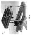
図4を参照すると、光学特徴付け装置100を形成するように変更され得るコンパクトなモードロックレーザーモジュール1−108の一例が示されている。いくつかの実施形態による、コンパクトなモードロックレーザーモジュール1−108は、レーザーキャビティ(レーザーキャビティの第1のエンドミラーとして機能することができる出力カプラ1−111と、レーザーキャビティの第2のエンドミラーとして機能することができる可飽和吸収体ミラー(SAM)1−119との間の光学素子を含む)と、モードロックレーザー1−110の構成要素の一部または全部が取り付けられる(ハウジングとも呼称される)成形ベースシャーシ2−105と、モードロックレーザーの動作を安定させることができる少なくとも1つのキャビティ内光学素子2−128と、レーザーからの出力をより短い波長に変換する際に協働することができる周波数2倍化要素2−170、2−164、2−160と、(光パワー等の)レーザーの動作パラメータを監視し、レーザーによって生成された光パルスに同期した電子クロック信号を生成する電気部品2−190、2−154、2−182、2−116とを含む。ポンプモジュール2−140は、ベースシャーシ2−105に取り付けられ、かつモードロックレーザーの利得媒体1−105を励起するために使用されることができる。
Mode Lock Laser Module With reference to FIG. 4, an example of a compact mode lock laser module 1-108 that can be modified to form the
いくつかの実施形態によると、コンパクトなモードロックレーザーモジュール1−108のベースシャーシ2−105は、長さLが約20cmと約30cmとの間、高さHが約10cmと約20cmとの間であり、厚さは約10cmと約30cmとの間である。いくつかの事例では、1つ又は複数の寸法が最大20%大きくなることがある。いくつかの実施形態によれば、コンパクトなモードロックレーザーモジュール1−108によって占有される容積は、約30cm×18cm×3cm、または約1620cm3であり得る。いくつかの実施形態によれば、モードロックレーザーモジュール1−108の全体形状またはフォームファクタは、高さHよりも長い長さLと、長さまたは高さのいずれかよりもはるかに小さい厚さとを有し、2850立方cm未満の容積を占有し、かつ重さが約2キログラム未満、または約2キログラムであるスラブである。いくつかの事例では、モジュール1−108の重量は1キログラム〜2キログラムである。 According to some embodiments, the base chassis 2-105 of the compact mode lock laser module 1-108 has a length L between about 20 cm and about 30 cm and a height H between about 10 cm and about 20 cm. And the thickness is between about 10 cm and about 30 cm. In some cases, one or more dimensions can be up to 20% larger. According to some embodiments, the volume occupied by the compact mode-locked laser module 1-108 may be about 30cm × 18cm × 3cm or about 1620 cm 3,. According to some embodiments, the overall shape or form factor of the mode-locked laser module 1-108 has a length L longer than the height H and a thickness much less than either the length or the height. A slab that occupies a volume of less than 2850 cubic cm and weighs less than about 2 kilograms, or about 2 kilograms. In some cases, modules 1-108 weigh between 1 and 2 kilograms.
いくつかの実施形態では、ベースシャーシ2−105は、アルミニウム、チタン、アルミニウムの合金、またはチタンの合金から形成することができる。他の実施形態では他の材料を使用することができる。いくつかの実施形態では、ベースシャーシ2−105は、ベースシャーシ内に機械加工または他の方法(例えば、鋳造または組み立てによって)で形成された複数のキャビティ2−102を含むことができる。いくつかの実施形態では、直径12.5mm(またはそれ以下)の光学部品が、モードロックレーザー1−110を構築するために使用され、かつベースシャーシ2−105のキャビティ2−102内に部分的または完全に埋め込まれることができ、カバー(図示せず)をキャビティ2−102の上に配置して、キャビティ内の構成要素を外部の環境要因および汚染物質から保護することができる。いくつかの実施形態では、カバーをキャビティ2−102上に配置して、1つまたは複数のキャビティを気密封止することができる。 In some embodiments, the base chassis 2-105 can be formed from aluminum, titanium, an alloy of aluminum, or an alloy of titanium. Other materials can be used in other embodiments. In some embodiments, the base chassis 2-105 can include a plurality of cavities 2-102 formed within the base chassis by machining or other methods (eg, by casting or assembly). In some embodiments, 12.5 mm (or less) diameter optics are used to construct the mode lock laser 1-110 and are partially within cavity 2-102 of base chassis 2-105. Alternatively, it can be fully embedded and a cover (not shown) can be placed over the cavities 2-102 to protect the components within the cavities from external environmental factors and contaminants. In some embodiments, the cover can be placed on cavities 2-102 to hermetically seal one or more cavities.
キャビティ2−102の間には、ベースシャーシ2−105内に形成されたリブ2−107を設けることができる。いくつかのリブには、キャビティ内レーザービームがリブを通って隣接するキャビティへ通過することを可能にする穴または開口部(視認できない)を設けることができる。いくつかの実施形態によれば、ベースシャーシ2−105の縁部に対して角度をなして延在する1つ又は複数の傾斜リブ2−107を設けることができる。例えば、傾斜リブ2−107は、ベースシャーシ2−105を横断する角部から角部への方向に延在することができる。傾斜リブ2−107は、傾斜リブを有しない場合と比較して、ベースシャーシ2−105のねじり剛性を3倍に増大させることができる。ねじり剛性が増加することで、レーザー動作の不安定性を防止し、ベースシャーシ2−105に作用する摂動力に対するモジュールの耐性を向上させるのに役立つ。いくつかの事例では、リブの少なくとも一部は、キャビティの底部からベースシャーシ2−105の上面まで延在して、レーザーモジュール1−108のための1つ又は複数のカバー(図示せず)をリブに取り付けることができる。これに関して、剛性金属カバー(例えば、約1mmを超える厚さを有する金属)、剛性ポリマーカバー(例えば、約2mmを超える厚さを有するポリマー)、またはベースシャーシ2−105に対してシールされるか、または支持片(例えば、金属フレーム)でベースシャーシ2−105に対して保持されることができる可撓性材料(金属またはポリマー)を含んだ任意の適切なカバーが使用され得るが、これらに限定されない。いくつかの事例では、カバー材料は、金属製フレーム(約1.5mm厚)を用いてベースシャーシに対して保持されているタイベック(Tyvek(登録商標))(約0.25mm厚)を含む。 Ribs 2-107 formed in the base chassis 2-105 can be provided between the cavities 2-102. Some ribs may be provided with holes or openings (not visible) that allow the intracavity laser beam to pass through the ribs to adjacent cavities. According to some embodiments, one or more inclined ribs 2-107 may be provided that extend at an angle to the edge of the base chassis 2-105. For example, the inclined rib 2-107 can extend in the corner-to-corner direction across the base chassis 2-105. The inclined rib 2-107 can increase the torsional rigidity of the base chassis 2-105 three times as compared with the case where the inclined rib is not provided. The increased torsional stiffness helps prevent instability in laser operation and improves the resistance of the module to perturbation acting on base chassis 2-105. In some cases, at least a portion of the ribs extends from the bottom of the cavity to the top surface of the base chassis 2-105 to provide one or more covers (not shown) for the laser modules 1-108. Can be attached to the rib. In this regard, is it sealed to a rigid metal cover (eg, a metal with a thickness greater than about 1 mm), a rigid polymer cover (eg, a polymer with a thickness greater than about 2 mm), or the base chassis 2-105? , Or any suitable cover containing a flexible material (metal or polymer) that can be held against the base chassis 2-105 by a support piece (eg, a metal frame) may be used. Not limited. In some cases, the cover material includes Tyvek® (approximately 0.25 mm thick) held against the base chassis using a metal frame (approximately 1.5 mm thick).
いくつかの実施形態では、1つまたは複数の取り付け機構2−103を1つまたは複数のリブ2−107に配置することができる。取り付け機構2−103は、コンパクトなレーザーモジュール1−108を機器または他のプラットフォームに取り付けるために使用することができる。いくつかの場合において、取り付け機構はキネマティックマウントを提供して、各レーザーモジュール1−108、または同じレーザーモジュールが、ほぼ同じ位置および位置合わせで(例えば、±100ミクロン以内まで)再現可能に取り付けられるようになる。キネマティックマウントは、取り付け処理によって生じるストレスを軽減し得る。取り付け機構2−103は、タップが切られているか、または空の状態である穴を含み得る。穴は皿穴加工されるか、または座ぐり加工されることができる。キネマティックマウントの場合、底面(図4には図示せず)が第1の取り付け機構のための円錐形接触面またはリング接触、第2の取り付け機構のためのくさび状接触面または2点接触面、および第3の取り付け機構のための平面または1点接触を含む3つの取り付け機構2−103を設けることができる。代替的に、取り付け機構2−103において2つの皿穴加工された穴を使用して、ベースシャーシ2−105を受承支持構造に位置合わせすることができる。 In some embodiments, one or more mounting mechanisms 2-103 can be arranged on one or more ribs 2-107. Mounting mechanism 2-103 can be used to mount the compact laser module 1-108 to equipment or other platforms. In some cases, the mounting mechanism provides a kinematic mount for each laser module 1-108, or the same laser module, to be reproducibly mounted in approximately the same position and alignment (eg, within ± 100 microns). Will be able to. Kinematic mounts can reduce the stress caused by the mounting process. Mounting mechanism 2-103 may include holes that are tapped or empty. The holes can be countersunk or counterbore. For kinematic mounts, the bottom surface (not shown in FIG. 4) is a conical or ring contact for the first mounting mechanism, a wedge contact or two-point contact for the second mounting mechanism. , And three mounting mechanisms 2-103, including a planar or one-point contact for a third mounting mechanism. Alternatively, two countersunk holes in the mounting mechanism 2-103 can be used to align the base chassis 2-105 to the receiving support structure.
レーザーモジュール1−108のモードロックレーザー110は、レーザーのキャビティの出力端にある出力カプラ1−111、利得媒体1−105、およびレーザーキャビティの反対側の端部にある可飽和吸収体ミラー(SAM)1−119を含むことができる。レーザーキャビティ内に複数のミラー2−116、2−117、2−120、2−121、2−122、2−123、2−124、2−125を配置して、レーザーの光軸1−125を折り返して、レーザーキャビティの長さを延長して、所望のパルス繰り返し率またはパルス分離間隔Tを達成することができる。レーザーキャビティ内にビーム整形光学系(例えば、レンズおよび/または曲面ミラー)を配置して、キャビティ内レーザービームのサイズおよび/または形状を変更することもできる。
The mode-locked
ここで、1064nmのレーザー発振波長で動作するモードロックレーザー用の例示的な光学部品について説明する。本発明の実施形態は記載された光学部品のみに限定されないことが理解されるであろう。いくつかの実施形態では、より少ないか、またはより多い光学部品を使用することができ(例えば、パルス繰り返し率を変更するためにミラーを追加または除去する)、部品上の光学コーティングは、異なる波長でレーザー発振するレーザーに対して異なるものとすることができる。 Here, exemplary optical components for mode-locked lasers operating at a laser oscillation wavelength of 1064 nm will be described. It will be appreciated that embodiments of the present invention are not limited to the optical components described. In some embodiments, fewer or more optics can be used (eg, mirrors are added or removed to change the pulse repetition rate), and the optical coatings on the components have different wavelengths. It can be different for the laser that oscillates with the laser.
利得媒体1−105は、ベースシャーシ2−105内に熱を放散する熱伝導性マウント(例えば、アルミニウムまたは銅のブロックまたは他の熱伝導性材料)に取り付けられたネオジムドープ材料を含むことができる。モードロックレーザーが高い平均パワー(例えば、300mWを超える)で動作すると、利得媒体1−105において熱レンズ効果が生じる。いくつかの事例では、そのような熱レンズ効果はレーザーの動作を不安定にする可能性がある。利得媒体から熱伝導性マウントへの熱伝達を改善するために、利得媒体1−105をインジウム箔または熱伝導性マウントへの熱伝達を改善する他の適切な材料で包装することができる。いくつかの事例では、銀エポキシまたは他の適切な熱伝導性接着剤を使用して利得結晶を熱マウントに固定することができる。いくつかの事例では、利得媒体1−105および熱伝導性マウントは、熱をベースシャーシ2−105に逃がすことができる熱電クーラー(TEC : thermo-electric cooler)に取り付けることができる。TECまたは液体冷却などの他の能動的冷却技術は、利得媒体1−105の能動的温度制御を提供し、熱レンズ効果を減少させることができる。 The gain medium 1-105 can include a neodymium-doped material mounted on a thermally conductive mount (eg, a block of aluminum or copper or other thermally conductive material) that dissipates heat within the base chassis 2-105. .. When the mode lock laser operates at a high average power (eg, above 300 mW), a thermal lens effect occurs in the gain medium 1-105. In some cases, such a thermal lens effect can destabilize the operation of the laser. To improve heat transfer from the gain medium to the heat conductive mount, the gain medium 1-105 can be packaged with indium foil or other suitable material that improves heat transfer to the heat conductive mount. In some cases, silver epoxies or other suitable thermally conductive adhesives can be used to secure the gain crystals to the thermal mount. In some cases, the gain medium 1-105 and the thermally conductive mount can be mounted on a thermo-electric cooler (TEC) that can dissipate heat to the base chassis 2-105. Other active cooling techniques, such as TEC or liquid cooling, can provide active temperature control of the gain medium 1-105 and reduce the thermal lens effect.
利得媒体1−105の能動的冷却を排除することは、レーザーのコストおよび複雑性を低減することができる。最大10ワットの光ポンピングパワーが利得媒体をポンピングするために使用される場合であっても、利得媒体の能動的温度制御を本実施形態のモードロックレーザー110に使用する必要がない。驚くべきことに、関連する熱レンズ効果(正レンズ効果)がポンプの出力範囲に亘って利得媒体の熱誘起焦点距離を0から約15ジオプタに変えることができるとしても、モードロックレーザー110はこの範囲のポンプパワーに亘って安定してモードロックされたままである。15ジオプタを超える熱レンズ効果の場合、レーザーキャビティは、モードロック動作や連続波動作をサポートできない不安定な共振器になる可能性がある。利得媒体におけるこのような広範囲の熱レンズ効果にわたるモードロックの安定性は、部分的にはモードロックレーザー110のための光学部品の選択および配置によるものである。一実施形態によれば、モードロック動作の安定性および改善された性能は、ある量の熱レンズ効果を利得媒体内で生じさせることに大きく依存する。実施形態では、1ジオプタと15ジオプタとの間の正のレンズ効果の熱レンズ効果の量に対して、モードロックレーザー110の安定したモードロック動作を得ることができる。熱レンズ効果がこの範囲に亘って変化しても、安定したモードロックを維持するためにレーザーキャビティに対して機械的調整を行う必要はない。利得媒体1−105内の熱レンズ効果の量が8ジオプタと12ジオプタとの間の正の熱レンズ効果であるとき、モードロックレーザーの改善された性能を得ることができる。連続波動作では、0ジオプタと少なくとも15ジオプタとの間の正の熱レンズ効果があり得る。熱レンズ効果の量(約4ジオプタを超える)は、(例えば、ヘリウムネオンレーザーまたはレーザーダイオードからの)連続波レーザープローブビームを(例えば、ある角度で)利得媒体1−105を通過させて、「ポンプビームオン」状態と「ポンプビームオフ」状態との間で利得媒体から一定の距離を置いてプローブビームの相対変位を測定することによって測定することができる。ポンプビームオン状態は、レーザーダイオードのポンプビームがオンであり、レーザー110のモードロックレーザー発振のために利得媒体1−105を励起するときである。相対変位が小さくなるため、4ジオプタ以下の値を正確に測定することは困難である。
Eliminating the active cooling of the gain medium 1-105 can reduce the cost and complexity of the laser. Even if up to 10 watts of optical pumping power is used to pump the gain medium, active temperature control of the gain medium need not be used for the mode-locked
利得媒体1−105における光ポンプビームの吸収は、利得媒体において熱レンズ効果を引き起こす可能性がある。実施形態では、利得媒体における熱レンズ効果の量は、利得媒体1−105に適用される光ポンプビームのパワー量を変化させること(例えば、ポンプモジュール2−140からのパワー量を変化させること)によって変化させることができる。追加的または代替的に、利得媒体内の熱レンズ効果の量は、利得媒体1−105を励起するために使用される光ポンプビームの光波長を調整することによって変化させることができる。光ポンプビームの波長の調整は、例えば、ポンプモジュール2−140内のレーザーダイオードの温度を調整することによって実行することができる。ポンプビームの波長を調整することは、利得媒体1−105における光ポンプビームの吸収量を変化させることができる。 Absorption of the optical pump beam in the gain medium 1-105 can cause a thermal lens effect in the gain medium. In an embodiment, the amount of thermal lens effect in the gain medium changes the amount of power of the optical pump beam applied to the gain medium 1-105 (eg, changing the amount of power from pump module 2-140). Can be changed by. Additional or alternative, the amount of thermal lens effect in the gain medium can be varied by adjusting the light wavelength of the optical pump beam used to excite the gain medium 1-105. The wavelength of the optical pump beam can be adjusted, for example, by adjusting the temperature of the laser diode in the pump module 2-140. Adjusting the wavelength of the pump beam can change the absorption amount of the optical pump beam in the gain medium 1-105.
いくつかの実施態様では、利得媒体1−105は、1064nmでのレーザー発振を提供することができるバナジン酸ネオジム(neodymium vanadate)(例えば、Nd3+:YVO4)を含むことができる。他の実施形態では、Nd:YAG、Nd:YLF、およびCr:フォルステライトなどであるが、これらに限定されない他の固体結晶を使用することができる。いくつかの実施形態では、キャビティ内の光学部品がこの波長でレーザー発振するように設計されコーティングされている限り、バナジン酸ネオジム利得媒体1−105を使用して1342nmでレーザー発振を代替的または付加的に提供することができる。利得媒体は、いくつかの事例では、3mm〜11mmの長さを有することができる。いくつかの実施形態では、利得媒体の長さは5mm〜9mmであり得る。いくつかの事例では、ネオジムドーパントレベル(原子%)は0.10%〜1%とすることができる。いくつかの実施形態では、ドーパントレベルは0.10%〜0.50%とすることができる。いくつかの実施形態では、ドーパントレベルは0.24%〜0.30%とすることができる。いくつかの実施形態によれば、結晶長は約7mmとすることができ、ドーパントレベルは約0.27%とすることができる。約7mmの長さに対して0.3%よりかなり高いドーピングレベル(原子%)が、より高い動作パワーでのレーザーの動作を不安定にし(例えば、高次空間モードでレーザー発振を誘発するか、またはモードロックを不安定にするかまたは終了させる)、これは、キャビティ内部品を再調整することを不所望に必要とする可能性がある。例えば、1%ドーピングでは、モードロックがあるポンプパワーレベルを超えて終了され、モードロックを回復するためにキャビティ内光学素子を再調整しなければならなかった。利得媒体1−105の横方向寸法(単数または複数)は、任意の適切な値(例えば、1mm〜4mm)とすることができる。利得媒体は、円筒形ロッド、矩形バー、または他の任意の形状の形態とすることができる。 In some embodiments, the gain medium 1-105 can include neodymium vanadate (eg, Nd 3+ : YVO4) capable of providing laser oscillation at 1064 nm. In other embodiments, other solid crystals such as, but not limited to, Nd: YAG, Nd: YLF, and Cr: forsterite can be used. In some embodiments, neodymium vanadate gain medium 1-105 is used to replace or add laser oscillation at 1342 nm, as long as the optics in the cavity are designed and coated to oscillate at this wavelength. Can be provided as a target. The gain medium can have a length of 3 mm to 11 mm in some cases. In some embodiments, the length of the gain medium can be 5 mm to 9 mm. In some cases, the neodymium dopant level (atomic%) can be 0.10% to 1%. In some embodiments, the dopant level can be between 0.10% and 0.50%. In some embodiments, the dopant level can be between 0.24% and 0.30%. According to some embodiments, the crystal length can be about 7 mm and the dopant level can be about 0.27%. Does a doping level (atomic%) significantly higher than 0.3% for a length of about 7 mm destabilizes the operation of the laser at higher operating powers (eg, induces laser oscillation in higher spatial modes)? , Or destabilizing or terminating the mode lock), which may undesirably require readjustment of the in-cavity component. For example, with 1% doping, the mode lock was terminated above a certain pump power level and the intracavity optics had to be readjusted to restore the mode lock. The lateral dimension (s) of the gain medium 1-105 can be any suitable value (eg, 1 mm to 4 mm). The gain medium can be in the form of a cylindrical rod, rectangular bar, or any other shape.
いくつかの実施形態では、利得媒体1−105の端面は、レーザー発振波長λl(バナジン酸ネオジムの場合、約1064nmであり得る)およびポンプ波長λp(バナジン酸ネオジムの場合、約808nmであり得る)に対して反射防止コーティングされ得る。いくつかの実施形態では、利得媒体の一方の端面を出力カプラコーティングで被覆して、端面がレーザーキャビティのエンドミラーとして機能し、別個の出力カプラ1−111を使用する必要がないようにすることができる。 In some embodiments, the end face of the gain medium 1-105 has a laser oscillation wavelength λ l (which can be about 1064 nm for neodymium vanadate) and a pump wavelength λ p (about 808 nm for neodymium vanadate). Can be anti-reflective coated against. In some embodiments, one end face of the gain medium is coated with an output coupler coating so that the end face acts as an end mirror of the laser cavity, eliminating the need to use a separate output coupler 1-111. Can be done.
利得媒体1−105は、レーザーキャビティの光軸1−125に対して約1度と約3度との間の角度に配向された法線ベクトルを利得媒体の端面が有するような向きで、非調整可能なマウント(微細な角度調整または位置調整を提供しないマウント)に取り付けることができる。例えば、利得媒体用の熱伝導性マウントは、利得媒体1−105が配置される凹部を含むことができる。凹部は、利得媒体を熱伝導性マウントに整列させることができる。熱伝導性マウントは、ベースシャーシ2−105上の特徴(例えば、機械加工された表面、ピン、ねじ穴のうちのいずれか1つまたはそれらの組み合わせ)に位置合わせして、利得媒体をレーザーキャビティの光軸1−125に対してある角度で位置合わせさせることができる。いくつかの実施形態によれば、利得媒体1−105は、レーザー発振を目的とした好ましい偏光と整列するように、そのマウント内でカットおよび配向されることができる。例えば、利得媒体1−105は、図4のY軸に平行な直線偏光でレーザー発振するように配向することができる。 The gain medium 1-105 is oriented such that the end face of the gain medium has a normal vector oriented at an angle between about 1 degree and about 3 degrees with respect to the optical axis 1-125 of the laser cavity, and is not oriented. It can be attached to adjustable mounts (mounts that do not provide fine angle or alignment). For example, a thermally conductive mount for a gain medium can include a recess in which the gain medium 1-105 is located. The recesses allow the gain medium to be aligned with the thermally conductive mount. The thermally conductive mount aligns the gain medium with a feature on the base chassis 2-105 (eg, one or a combination of machined surfaces, pins, screw holes) and the laser cavity. It can be aligned at a certain angle with respect to the optical axis 1-125 of. According to some embodiments, the gain medium 1-105 can be cut and oriented within its mount to align with the preferred polarization intended for laser oscillation. For example, the gain medium 1-105 can be oriented so as to oscillate a laser with linearly polarized light parallel to the Y-axis of FIG.
いくつかの実施形態によれば、コンパクトなモードロックレーザー用の出力カプラ1−111は、表面品質が10〜5(スクラッチおよびディグ)であり、波面誤差が最大でλ/10の高品質のレーザー光学素子とすることができる。出力カプラ1−111の一方の表面は多層誘電体で被覆されて、レーザー発振波長λlに対して約75%と約95%との間の値を有する反射率を提供し、かつ(最小の反射率で)利得媒体1−105を励起するために使用されるポンプ波長λpの透過を可能にする。いくつかの実施形態では、レーザー発振波長は約1064nmであり、ポンプ波長は約808nmであり得るが、他の実施形態では、他の波長を使用することができる。いくつかの実施形態では、レーザー発振波長での出力カプラの反射率は82%と88%との間である。この範囲の反射率内の出力カプラが、レーザーの安定動作で所望の量の出力パワーを提供し、かつレーザーの動作範囲に亘って可飽和吸収体ミラー1−119上に適切な量のフルエンスを提供する。 According to some embodiments, the output coupler 1-111 for a compact mode-locked laser is a high quality laser with a surface quality of 10-5 (scratch and dig) and a maximum wavefront error of λ / 10. It can be an optical element. One surface of the output coupler 1-111 is coated with a multilayer dielectric to provide reflectance having a value between about 75% and about 95% with respect to the laser oscillation wavelength λ l, and (minimum). Allows transmission of the pump wavelength λ p used to excite the gain medium 1-105 (at reflectance). In some embodiments, the laser oscillation wavelength can be about 1064 nm and the pump wavelength can be about 808 nm, but in other embodiments, other wavelengths can be used. In some embodiments, the reflectance of the output coupler at the laser oscillation wavelength is between 82% and 88%. Output couplers within this range of reflectance provide the desired amount of output power for stable laser operation and provide an appropriate amount of fluence on the saturable absorber mirror 1-119 over the range of laser operation. offer.
出力カプラ1−111の第2の面(レーザー出力側)は、ポンプ波長とレーザー発振波長の両方に対して反射防止コーティングで被覆することができ、かつ出力カプラの反射面に対してある角度(例えば、約1度と約4度との間)で配向されることができる。出力カプラ1−111の出力(透過)面からのレーザー発振波長の少量の反射が、モードロックレーザーからのパルスを著しくかつ不利に広げる可能性がある。いくつかの実施形態によれば、出力カプラ上のコーティングは、ごくわずかな反射でポンプ波長λpを透過させるように二色性である。 The second surface (laser output side) of the output coupler 1-111 can be coated with an antireflection coating for both the pump wavelength and the laser oscillation wavelength, and at an angle (on the reflective surface of the output coupler). For example, it can be oriented between about 1 degree and about 4 degrees). A small amount of reflection of the laser oscillation wavelength from the output (transmissive) surface of the output coupler 1-111 can significantly and unfavorably spread the pulse from the mode-locked laser. According to some embodiments, the coating on the output coupler is dichroic so that it transmits the pump wavelength λ p with very little reflection.
いくつかの実施形態によれば、出力カプラ1−111は、2つの直交軸(例えば、図4のY軸およびX軸を中心とする)の周りで光軸1−125に対して角度調整を提供する2軸調整マウントに取り付けることができる。いくつかの実施形態では、出力カプラ1−111は、ベースシャーシ2−105に一体化することができる非調整可能なマウントに取り付けることができる。非調整可能なマウントは、コンパクトなレーザーのコストおよび複雑性を低減する。さらに他の実施形態では、出力カプラ1−111は、透明基板と1つまたは複数の光学コーティングとを備える別個の光学部品の代わりに、利得媒体1−105の端面上の多層光学コーティングとして形成することができる。 According to some embodiments, the output coupler 1-111 adjusts the angle around the two orthogonal axes (eg, centered on the Y and X axes in FIG. 4) with respect to the optical axes 1-125. It can be attached to the provided 2-axis adjustment mount. In some embodiments, the output coupler 1-111 can be attached to a non-adjustable mount that can be integrated with the base chassis 2-105. Non-adjustable mounts reduce the cost and complexity of compact lasers. In yet another embodiment, the output coupler 1-111 is formed as a multilayer optical coating on the end face of the gain medium 1-105 instead of a separate optical component with a transparent substrate and one or more optical coatings. be able to.
出力カプラ1−111と利得媒体1−105との間の距離を変更することによって、モードロックパルスの時間プロファイル(パルス持続時間とも呼ばれる)のFWHM値を変更することができる。レーザーのモードロックは、出力カプラ1−111と利得媒体1−105との間の距離を0mmから10mmの間で変化させることによって達成することができ、パルス持続時間は、約9ピコ秒から約38ピコ秒の間で変化させることができる。この範囲の距離は、異なるパルス幅を得るために異なる距離を選択することによって得られる。いくつかの実施形態によれば、出力カプラ1−111と利得媒体1−105との間の距離は、4mmと8mmとの間に設定される。 By changing the distance between the output coupler 1-111 and the gain medium 1-105, the FWHM value of the mode lock pulse time profile (also referred to as pulse duration) can be changed. Laser mode lock can be achieved by varying the distance between the output coupler 1-111 and the gain medium 1-105 from 0 mm to 10 mm, with pulse durations ranging from about 9 picoseconds to about. It can be varied between 38 picoseconds. Distances in this range are obtained by choosing different distances to obtain different pulse widths. According to some embodiments, the distance between the output coupler 1-111 and the gain medium 1-105 is set between 4 mm and 8 mm.
出力カプラ1−111におけるレーザーのキャビティ内ビームウェストが(1/e2で測定されたビーム半径の)100ミクロンから180ミクロンの間であるときに、ある範囲の平均レーザー発振パワーにわたって安定で効率的な動作が達成される。出力カプラ1−111におけるビームウェストの値は、曲面ミラー2−117のようなキャビティ内光学素子によって、出力カプラから曲面ミラーまでの距離によって、および利得媒体1−105内のポンプビームウェストによって部分的に決定される。いくつかの実施形態によれば、利得媒体におけるレーザー発振波長のビームウェストは、利得媒体1−105におけるポンプビームウェストよりも著しく小さくすることができる。例えば、利得媒体におけるレーザー発振波長に対するビームウェストは、利得媒体において100ミクロンと150ミクロンとの間とすることができ、ポンプビームに対する最小ウェストは、180ミクロンと250ミクロンとの間とすることができ、ポンプビームは、その光軸に関して完全に対称的ではないものとし得る。出力カプラ1−111における、かつ利得媒体1−105内のビームウェストの値はまた、第2の曲面ミラー2−127の焦点距離および可飽和吸収体ミラー1−119までの第2の曲面ミラー2−127の距離によって影響され得る。レーザーダイオードポンプビームよりもモードロックレーザー1−110のレーザー発振ビームに対するビームウェストを小さくすることは、モードロックレーザー動作の安定性を改善することができる(例えば、レーザーが利得媒体1−105内のレーザービームとレーザーダイオードポンプビームとの相対運動によるパワー変動およびモードロック変動の影響を受けにくくすることができる)。用語「ビームウェスト」は、レーザービーム強度がビームの両側でピーク値から1/e2値まで低下する空間的範囲を指すために使用される。円形ビームは、単一ビームウェストによって特徴付けられ得る。楕円形のビームは、ビームの短軸に対するビームと長軸に対するビームの2つのビームウェストで特徴付けられ得る。 Stable and efficient over a range of average laser oscillation powers when the intracavity beam waist of the laser in the output coupler 1-111 is between 100 and 180 microns (of the beam radius measured at 1 / e 2). Operation is achieved. The beam waist value at the output coupler 1-111 is partially determined by the intracavity optics such as curved mirror 2-117, by the distance from the output coupler to the curved mirror, and by the pump beam waist in the gain medium 1-105. Is decided on. According to some embodiments, the beam waist of the laser oscillation wavelength in the gain medium can be significantly smaller than the pump beam waist in the gain medium 1-105. For example, the beam waist for the laser oscillation wavelength in the gain medium can be between 100 and 150 microns in the gain medium, and the minimum waist for the pump beam can be between 180 and 250 microns. , The pump beam may not be perfectly symmetrical with respect to its optical axis. The value of the beam waist in the output coupler 1-111 and in the gain medium 1-105 is also the focal length of the second curved mirror 2-127 and the second curved mirror 2 up to the saturable absorber mirror 1-119. It can be affected by a distance of -127. Making the beam waist of the mode-locked laser 1-110 relative to the laser oscillation beam smaller than that of the laser diode pump beam can improve the stability of the mode-locked laser operation (eg, the laser is in the gain medium 1-105). It can be less affected by power fluctuations and mode lock fluctuations due to the relative motion of the laser beam and the laser diode pump beam). The term "beam waist", the laser beam intensity is used to refer to a spatial range decreases from the peak value to the 1 / e 2 value on both sides of the beam. The circular beam can be characterized by a single beam waist. An elliptical beam can be characterized by two beam waists, one for the short axis of the beam and one for the long axis.
レーザーキャビティの反対側の端部には、可飽和吸収体ミラー(SAM)1−119が取り付けられ得る。SAMは、非線形光吸収を示す多層半導体構造(例えば、多重量子井戸)と、基板上に形成された高反射器とを含むことができる。非線形光吸収は、レーザーに受動モードロックを誘起することができる。例えば、SAMは、低い光強度でより高い吸収および損失を示し、高い光強度でブリーチングするかまたはほとんど吸収を示さず、かつより少ない損失を示し得る。半導体構造は、高反射器に入射し、ほぼ、高反射器から反射される光場によって作成される光定在波のピーク強度に半導体構造が位置するように、SAM内の高反射器から離間されることができる。SAMの一例は、BATOPオプトエレクトロニクス有限責任会社(BATOP Optoelectronics GmbH)[独国イェナ(Jena)所在]から入手可能な品番SAM−1064−5−10ps−xである。SAMの非線形光吸収のため、高強度の光パルスは低強度の連続波レーザー動作よりもキャビティ内での損失が少ないので、レーザーはパルス動作モード(受動モードロック)で優先的に動作する。 A saturable absorber mirror (SAM) 1-119 may be attached to the opposite end of the laser cavity. The SAM can include a multilayer semiconductor structure exhibiting non-linear light absorption (for example, multiple quantum wells) and a high reflector formed on a substrate. Non-linear light absorption can induce passive mode lock in the laser. For example, SAM may exhibit higher absorption and loss at low light intensity, bleaching at high light intensity or little absorption, and less loss. The semiconductor structure is incident on the high reflector and is separated from the high reflector in the SAM so that the semiconductor structure is located approximately at the peak intensity of the light standing wave created by the light field reflected from the high reflector. Can be done. An example of SAM is part number SAM-1064-5-10ps-x available from BATOP Optoelectronics GmbH [located in Jena, Germany]. Due to the non-linear light absorption of the SAM, high intensity light pulses have less loss in the cavity than low intensity continuous wave laser operation, so the laser operates preferentially in pulse operation mode (passive mode lock).
いくつかの実施形態によれば、SAMはヒ化ガリウム半導体組成物から形成することができる。SAMは、より大きな基板またはウェーハから切り取ることができ、SAMの面を横切る最大寸法が1mmと3mmとの間の正方形の形状とすることができる。SAMの吸収の緩和時間は10psと30psとの間とすることができる。SAMの不飽和吸収は、2%と6%との間とすることができる。SAMの変調度は、SAMの不飽和吸収の60%と74%との間とすることができる。いくつかの実施態様では、緩和時間は約25psであり、非飽和吸収は約4%である。そのようなSAM1−119は、12psと20psとの間のパルス持続時間を有するモードロックレーザー発振をサポートすることができる。いくつかの実施形態では、SAMの飽和フルエンスは、約70マイクロジュール/cm2(μJ/cm2)とすることができる。 According to some embodiments, the SAM can be formed from a gallium arsenide semiconductor composition. The SAM can be cut from a larger substrate or wafer and can have a square shape with a maximum dimension across the surface of the SAM between 1 mm and 3 mm. The relaxation time for absorption of SAM can be between 10 ps and 30 ps. The unsaturated absorption of SAM can be between 2% and 6%. The degree of modulation of the SAM can be between 60% and 74% of the unsaturated absorption of the SAM. In some embodiments, the relaxation time is about 25 ps and the unsaturated absorption is about 4%. Such a SAM 1-119 can support mode-locked laser oscillations with pulse durations between 12 ps and 20 ps. In some embodiments, the saturated fluence of SAM can be about 70 microjoules / cm 2 (μJ / cm 2 ).
ヒ化ガリウムSAMの長期動作のためには、キャビティ内レーザービームからのSAM上の光フルエンスが2.5ミリジュール/cm2(mJ/cm2)未満に保たれるべきであることを認識し、諒解した。5mJ/cm2以上の値では、SAMが損傷する可能性がある。いくつかの実施形態では、SAM上のフルエンスは、SAMの飽和フルエンスの約10倍未満に保つことができる。SAM上のフルエンスは、SAMにおけるビームウェストを制御することによって(例えば、レーザーキャビティ内に配置された曲面ミラー2−127を用いて)、および出力カプラ1−111の反射率を選択してキャビティ内パワーを制御することによって制御することができる。いくつかの実施形態によれば、SAMにおけるビームウェストは、出力カプラ反射率が82%と88%との間であるとき、80ミクロンと120ミクロンとの間とすることができる。 Recognizing that for long-term operation of gallium arsenide SAM, the optical fluence on the SAM from the intracavity laser beam should be kept below 2.5 millijoules / cm 2 (mJ / cm 2). I understand. At values of 5 mJ / cm 2 and above, the SAM may be damaged. In some embodiments, the fluence on the SAM can be kept less than about 10 times the saturated fluence of the SAM. Fluence on the SAM can be achieved by controlling the beam waist in the SAM (eg, using a curved mirror 2-127 placed in the laser cavity) and by selecting the reflectance of the output coupler 1-111 in the cavity. It can be controlled by controlling the power. According to some embodiments, the beam waist in the SAM can be between 80 microns and 120 microns when the output coupler reflectance is between 82% and 88%.
出力カプラ1−111とSAM1−119との間に、レーザーキャビティの光軸を複数回折り返す複数のミラーを設けることができる。これらのミラーのいくつか(例えば、ミラー2−115、2−120、2−121、2−122、2−123、2−124、2−125)は、平坦な面を有することができ、かつ非調整可能なマウントに取り付けられることができる。いくつかの実施形態によれば、2つのミラー2−117、2−127は曲面を有することができ、かつ集束反射器(focusing reflector)を含むことができる。いくつかの事例では、ミラー2−117、2−127用の集束反射器の代わりに、他のタイプの集束光学系(focusing optic)(例えば、レンズまたは複合レンズ)を使用することができる(例えば、キャビティ内ビームがミラー2−117またはミラー2−127の位置で折り返されない場合)。レーザーの光軸を折り返すために使用される平面ミラーおよび曲面ミラーに関して、ミラーの反射率は、ミラーが使用される入射角でのレーザー発振波長に対して非常に高くなり得る。例えば、そのようなミラーの反射率は、ある場合には99%よりも大きく、さらにある場合には99.5%よりも大きくすることができる。1つまたは複数の折り返しミラーの表面品質は、少なくとも10〜5(スクラッチおよびディグ)とすることができ、波面誤差は最大でλ/10とすることができる。いくつかの事例では、1つまたは複数の折り返しミラーの表面品質は、少なくとも40〜20(スクラッチおよびディグ)とすることができ、波面誤差は最大でλ/10とすることができる。スクラッチおよびディグの表面品質に対するより高い値は、折り返しミラーのコストを大幅に削減することができる。 A plurality of mirrors that fold back a plurality of optical axes of the laser cavity can be provided between the output coupler 1-111 and the SAM 1-119. Some of these mirrors (eg, mirrors 2-115, 2-120, 2-121, 2-122, 2-123, 2-124, 2-125) can have flat surfaces and Can be attached to non-adjustable mounts. According to some embodiments, the two mirrors 2-117, 2-127 can have a curved surface and can include a focusing reflector. In some cases, other types of focusing optics (eg, lenses or composite lenses) can be used instead of the focusing reflectors for mirrors 2-117, 2-127 (eg, lenses or composite lenses). , If the in-cavity beam does not fold back at the position of mirror 2-117 or mirror 2-127). For planar and curved mirrors used to fold the optical axis of a laser, the reflectance of the mirror can be very high relative to the laser oscillation wavelength at the angle of incidence at which the mirror is used. For example, the reflectance of such mirrors can be greater than 99% in some cases and even greater than 99.5% in other cases. The surface quality of one or more folded mirrors can be at least 10-5 (scratches and digs) and the wavelength error can be up to λ / 10. In some cases, the surface quality of one or more folded mirrors can be at least 40-20 (scratch and dig) and the wave surface error can be up to λ / 10. Higher values for scratch and dig surface quality can significantly reduce the cost of folded mirrors.
いくつかの実施形態では、ミラーのうちの少なくとも1つ(たとえば、ミラー2−124)は、利得媒体1−105からSAM1−119への単一の通過のためにキャビティ内ビームを複数回折り返すことができる。図4に示す例示的な構成では、利得媒体1−105からSAM1−119に進む光パルス1−120の跳ね返りシーケンスは、ミラー2−115、2−117、2−120、2−121、2−122、2−123、2−124、2−125、2−124、2−127、2−124からSAM1−119に達する反射のシーケンスである。このシーケンスでは、キャビティ内ミラーのうちの1つのミラー2−124が多重反射のために使用され、ビームがレーザーキャビティの一端から他端へ進むときに、少なくとも2回の反射に対してこのミラー上で入射角の符号が反転される。例えば、図4を参照すると、ビームが出力カプラ1−111からSAM1−119に進むとき、ミラー2−124上の第1の入射角は+Z方向であり、第2の入射角は−Z方向である。SAM1−119から反射した後、パルスは次に逆跳ね返りシーケンスで利得媒体に戻る。コンパクトなレーザーモジュール内で光軸が複数回折り返すことによって、キャビティ長を延長して、200MHz未満で50MHz程度の低いパルス繰り返し率を得ることができる。パルス繰り返し率は、レーザーキャビティの長さに依存し、これは、キャビティ内のミラー間の跳ね返りの数およびミラー間の距離によって部分的に決定される。いくつかの実施形態によれば、パルス繰り返し率は、ミラーを再配置し、かつ第1の曲面ミラー2−117と第2の曲面ミラー2−127との間のキャビティ内のミラーを追加または除去して、出力カプラ1−110と可飽和吸収体ミラー1−119との間の光路長を増減することによって変更することができる。キャビティ内ビームは第1の曲面ミラー2−117と第2の曲面ミラー2−127との間でほぼコリメートされているので、ビームがこの領域でコリメートされていない場合よりも、パルス繰り返し率への変更をより容易に行うことができる。いくつかの実施形態では、ミラーを再配置して異なるパルス繰り返し率を得るために、追加の一体型光学マウントをベースシャーシ内に形成することができる。 In some embodiments, at least one of the mirrors (eg, mirror 2-124) folds a plurality of intracavity beams for a single pass from the gain medium 1-105 to SAM1-119. Can be done. In the exemplary configuration shown in FIG. 4, the bounce sequence of the optical pulse 1-120 traveling from the gain medium 1-105 to SAM1-119 is mirror 2-115, 2-117, 2-120, 2-121, 2-. A sequence of reflections from 122, 2-123, 2-124, 2-125, 2-124, 2-127, 2-124 to SAM1-119. In this sequence, one of the in-cavity mirrors, mirror 2-124, is used for multiple reflections and is on this mirror for at least two reflections as the beam travels from one end to the other of the laser cavity. The sign of the incident angle is inverted. For example, referring to FIG. 4, when the beam travels from the output coupler 1-111 to SAM1-119, the first angle of incidence on mirror 2-124 is in the + Z direction and the second angle of incidence is in the −Z direction. be. After reflecting off SAM1-119, the pulse then returns to the gain medium in a reverse bounce sequence. By diffracting a plurality of optical axes in a compact laser module, the cavity length can be extended to obtain a low pulse repetition rate of about 50 MHz below 200 MHz. The pulse repetition rate depends on the length of the laser cavity, which is partially determined by the number of bounces between the mirrors in the cavity and the distance between the mirrors. According to some embodiments, the pulse repetition rate rearranges the mirrors and adds or removes mirrors in the cavity between the first curved mirror 2-117 and the second curved mirror 2-127. Then, it can be changed by increasing or decreasing the optical path length between the output coupler 1-110 and the saturable absorber mirror 1-119. Since the in-cavity beam is approximately collimated between the first curved mirror 2-117 and the second curved mirror 2-127, it is more likely to have a pulse repetition rate than if the beam were not collimated in this region. Changes can be made more easily. In some embodiments, additional integrated optical mounts can be formed within the base chassis to rearrange the mirrors to obtain different pulse repetition rates.
上記のように、本発明者らは、バイオ光電子チップ上のサンプルの超並列分析には、200MHz未満で50MHz程度の低いパルス繰り返し率が望ましいことを認識し、諒解した。しかしながら、複数回使用されるいくつかのミラーを有する複数のミラーを使用することは、何時間にも亘る安定したモードロックレーザー発振を維持するために、ミラーの互いに対する非常に高度の安定性を必要とする。補強リブを含むベースシャーシ2−105内の支持面に対してミラーを一体的に取り付けることにより、ミラーの必要な安定性および安定したモードロック動作を達成することができる。 As described above, the present inventors have recognized and understood that a low pulse repetition rate of less than 200 MHz and about 50 MHz is desirable for massively parallel analysis of samples on a biophotoelectron chip. However, using multiple mirrors with several mirrors used multiple times provides a very high degree of stability of the mirrors to each other in order to maintain stable mode-locked laser oscillations over hours. I need. By integrally mounting the mirror on the support surface in the base chassis 2-105 including the reinforcing ribs, the required stability and stable mode-locking operation of the mirror can be achieved.
いくつかの実施形態では、1つの折り返しミラー2−115は、キャビティ内の放射の偏光を制御し、ポンプビーム放射(図4の太い破線として示される)の監視を可能にするように構成することができる。例えば、折り返しミラー2−115は、偏光(ベースシャーシの面外へのY方向への偏光)を99%を超える高い反射率、さらに、いくつかの事例では、99.5%を超える高い反射率で反射し、かつ直交p偏光に対する反射率が低くなって、p偏光のレーザー発振が防止されるようにコーティングされることができる。いくつかの事例では、折り返しミラー2−115は、20%を超えるp偏光を透過させ、かつs偏光を高い反射率で反射する偏光ビームスプリッタとすることができる。折り返しミラー2−115はさらに、ミラーの後方に位置する光検出器2−116にポンプビーム放射の大部分またはほぼ全部を伝達することができる。いくつかの実施形態では、折り返しミラーは、ポンプビーム放射の透過を可能にするための二色性コーティング(dichroic coating)を含むことができる。他の実施形態では、二色性コーティングを使用しなくてもよく、レーザー発振波長用のコーティングは、検出のために折り返しミラー2−115を通過するポンプビーム放射の適切な透過を可能にし得る。光検出器2−116からの出力は、信号処理および/または外部信号プロセッサへの送信のためにPCB2−190に供給することができる。 In some embodiments, one folded mirror 2-115 is configured to control the polarization of the radiation in the cavity and allow monitoring of the pump beam radiation (shown as the thick dashed line in FIG. 4). Can be done. For example, the folded mirror 2-115 has a high reflectance of more than 99% of polarized light (polarization in the Y direction out of the plane of the base chassis), and in some cases, a high reflectance of more than 99.5%. It can be coated so as to prevent the laser oscillation of the p-polarized light by being reflected by the light and having a low reflectance with respect to the orthogonal p-polarized light. In some cases, the folded mirror 2-115 can be a polarization beam splitter that transmits more than 20% p-polarized light and reflects s-polarized light with high reflectance. The folded mirror 2-115 can further transmit most or almost all of the pump beam radiation to the photodetector 2-116 located behind the mirror. In some embodiments, the folded mirror can include a dichroic coating to allow the transmission of pump beam radiation. In other embodiments, the dichroic coating may not be used and the coating for the laser oscillation wavelength may allow proper transmission of pump beam radiation through the folded mirror 2-115 for detection. The output from photodetector 2-116 can be supplied to PCB 2-190 for signal processing and / or transmission to an external signal processor.
いくつかの実施形態では、利得媒体1−105およびSAM1−119内で所望のビームウェストサイズを得るために、2つの曲面ミラー2−117、2−127を設計し、レーザーキャビティ内に配置することができる。第1の曲面ミラー2−117は、利得媒体1−105の近傍のレーザーキャビティの第1の部分に配置することができる。第2の曲面ミラー2−127は、SAM1−119の近傍のレーザーキャビティの第2の部分に配置することができる。少なくとも曲面ミラーの間には、レーザーの光軸を折り返してキャビティ長延長領域においてレーザーキャビティの長さを延長する複数の折り返しミラーを設けることができる。キャビティ長延長領域においてキャビティの長さを延長するために、ミラー2−127とSAM1−119との間にキャビティ内レーザービームを複数回折り返すミラー2−124を追加的に設けることができる。例えば、図4に示すように、曲面ミラー2−127およびミラー2−124は、これら2つの反射器からのキャビティ内ビームを即時の連続的な跳ね返りで3回折り返すことができる。 In some embodiments, two curved mirrors 2-117, 2-127 are designed and placed in the laser cavity to obtain the desired beam waist size within the gain medium 1-105 and SAM1-119. Can be done. The first curved mirror 2-117 can be arranged in the first portion of the laser cavity in the vicinity of the gain medium 1-105. The second curved mirror 2-127 can be placed in the second portion of the laser cavity near SAM1-119. At least between the curved mirrors, a plurality of folded mirrors that fold the optical axis of the laser to extend the length of the laser cavity in the cavity length extension region can be provided. In order to extend the length of the cavity in the cavity length extension region, a mirror 2-124 that folds back a plurality of laser beams in the cavity can be additionally provided between the mirror 2-127 and the SAM 1-119. For example, as shown in FIG. 4, curved mirrors 2-127 and mirrors 2-124 can fold the intracavity beam from these two reflectors three times with immediate continuous bounce.
いくつかの実施形態によれば、第1の曲面ミラー2−117は、球面反射器とすることができ、かつ240mmと260mmとの間の焦点距離f1を有することができる。この反射器の焦点距離の許容誤差は、焦点距離の±1%とすることができる。本発明者らは、焦点距離が約250mmの第1の曲面ミラー2−117を出力カプラ1−111から230mmと310mmとの間に配置することができ、異なる特性を有する安定したモードロック動作を得ることができることを見出した。いくつかの実施形態によれば、第1の曲面ミラーを出力カプラから280mmと300mmとの間に配置して、コンパクトなレーザーモジュールの広範囲の動作パワーに亘って安定したモードロック動作を得ることができる。この構成では、利得媒体1−105を出力カプラから4mmと8mmとの間に配置することができる。第1の曲面ミラー2−117の焦点距離と利得媒体1−105および出力カプラ1−111に対する第1の曲面ミラー2−117の位置、および第2の曲面ミラー2−127の焦点距離とSAM1−119に対する第2の曲面ミラー2−127の位置は、利得媒体内のキャビティ内ビームのビームウェストを決定することができる。 According to some embodiments, the first curved mirror 2-117 can be a spherical reflector and can have a focal length f 1 between 240 mm and 260 mm. The focal length tolerance of this reflector can be ± 1% of the focal length. The present inventors can arrange the first curved mirror 2-117 having a focal length of about 250 mm between the output couplers 1-111 and 230 mm and 310 mm, and perform stable mode lock operation having different characteristics. I found that I could get it. According to some embodiments, a first curved mirror can be placed between 280 mm and 300 mm from the output coupler to obtain stable mode-locking operation over a wide range of operating powers of the compact laser module. can. In this configuration, the gain medium 1-105 can be placed between 4 mm and 8 mm from the output coupler. The focal length of the first curved mirror 2-117 and the position of the first curved mirror 2-117 with respect to the gain medium 1-105 and the output coupler 1-111, and the focal length of the second curved mirror 2-127 and SAM1- The position of the second curved mirror 2-127 with respect to 119 can determine the beam waist of the in-cavity beam in the gain medium.
他の実施形態では、第1の曲面ミラー2−117の焦点距離は他の値を有してもよい。例えば、より低いパワーで動作するよりコンパクトなモードロックレーザーに対しては、より短い焦点距離f1<230mmを使用することができる。実施形態において、出力カプラ1−111は、焦点距離f1の30%以内の値の範囲(例えば、0.7f1<d1<1.3f1)内にある第1の曲面ミラー2−117からの距離d1に配置することができる。いくつかの事例では、0.9f1<d1<1.3f1である。 In other embodiments, the focal length of the first curved mirror 2-117 may have other values. For example, a shorter focal length f 1 <230 mm can be used for a more compact mode-locked laser that operates at lower power. In an embodiment, the output coupler 1-111 is from a first curved mirror 2-117 within a range of values within 30% of the focal length f1 (eg, 0.7f 1 <d 1 <1.3f 1). it can be located a distance d 1. In some cases, 0.9f 1 <d 1 <1.3 f 1 .
いくつかの実施形態では、第1の曲面ミラー2−117は、レーザーの光軸に対するミラーの配向角度(面内の角度および面外の角度)を調整するための2つの自由度のみを提供する調整可能なマウントに取り付けられることができる。調整可能なマウントは、オペレータが、レーザーの動作を安定性、ビーム品質、出力パワー、および/またはパルス特性に関して調整することができるように、レーザーがレーザー発振している間に、光学部品の位置(X、Y、Zのうちの1つまたは複数)および/または向き(入射キャビティ内ビームの光軸に対するピッチおよび/またはヨー)を微調整することを可能にする。微調整は、例えば、ミラーマウント上でのマイクロメータ及び/又は微細にねじ切りされたねじ調整によって達成することができる。調整可能であることは、第1の曲面ミラー2−117の要件ではないことに留意されたい。さらに、レーザーキャビティを形成するように使用される他のミラーが、キャビティの位置合わせを微調整するように使用されてもよい。 In some embodiments, the first curved mirror 2-117 provides only two degrees of freedom for adjusting the mirror orientation angle (in-plane angle and out-of-plane angle) with respect to the optical axis of the laser. Can be attached to an adjustable mount. The adjustable mount allows the operator to adjust the operation of the laser with respect to stability, beam quality, output power, and / or pulse characteristics, while the laser oscillates, the position of the optics. Allows fine-tuning (one or more of X, Y, Z) and / or orientation (pitch and / or yaw of the beam in the incident cavity with respect to the optical axis). Fine adjustment can be achieved, for example, by a micrometer on a mirror mount and / or finely threaded screw adjustment. Note that being adjustable is not a requirement of the first curved mirror 2-117. In addition, other mirrors used to form the laser cavity may be used to fine-tune the alignment of the cavity.
レーザーがレーザー発振している間にリアルタイムでレーザーキャビティを位置合わせするための唯一の調整として、第1の曲面ミラー2−117に対して2つの自由度のみを提供し、折り返しミラー(例えば、ミラー2−123)に対して1つの自由度のみを提供することにより、コンパクトなモードロックレーザーモジュールのコストおよび複雑性を低減することができる。他の事例では、例えば、第1の曲面ミラー2−117用のミラーマウントは、ミラーの位置を調整するための追加の自由度を含むことができる。いくつかの実施形態によれば、ポンプビームを整列または再整列させ、モードロックレーザーからの出力パワーを増大させるために、曲面ミラー2−117を調整した後にポンプモジュール2−140に対する調整を行うことができる。 The only adjustment to align the laser cavity in real time while the laser is oscillating is to provide only two degrees of freedom for the first curved mirror 2-117 and a folded mirror (eg, mirror). By providing only one degree of freedom for 2-123), the cost and complexity of a compact mode-locked laser module can be reduced. In other cases, for example, the mirror mount for the first curved mirror 2-117 may include additional degrees of freedom for adjusting the position of the mirror. According to some embodiments, adjustments are made to the pump module 2-140 after adjusting the curved mirror 2-117 to align or rearrange the pump beams and increase the output power from the mode lock laser. Can be done.
第2の曲面ミラー2−127は球面反射器とすることができ、かつ240mmと260mmの間の焦点距離f2を有することができる。この反射器の焦点距離の許容誤差は、焦点距離の±1%とすることができる。本発明者らは、焦点距離が約250mmの第2の曲面ミラー2−127をSAM1−119から260mmと290mmとの間に配置することができ、異なる特性を有する安定したモードロック動作を得ることができることを見出した。いくつかの実施形態によれば、第2の曲面ミラーをSAM1−119から270mmと285mmとの間に配置して、コンパクトなレーザーモジュールの広範囲の動作パワーに亘って安定したモードロック動作を得ることができる。第2の曲面ミラー2−127の焦点距離およびSAM1−119に対する第2の曲面ミラー2−127の位置は、SAM1−119におけるキャビティ内ビームのビームウェストを決定することができ、かつ利得結晶におけるビームウェストにも影響を与えることができる。 The second curved mirror 2-127 can be a spherical reflector and can have a focal length f 2 between 240 mm and 260 mm. The focal length tolerance of this reflector can be ± 1% of the focal length. The present inventors can arrange a second curved mirror 2-127 having a focal length of about 250 mm between SAM 1-119 and 260 mm and 290 mm to obtain a stable mode lock operation having different characteristics. I found that I could do it. According to some embodiments, a second curved mirror is placed between SAM 1-119 and 270 mm and 285 mm to obtain stable mode-locking operation over a wide range of operating powers of the compact laser module. Can be done. The focal length of the second curved mirror 2-127 and the position of the second curved mirror 2-127 with respect to SAM1-119 can determine the beam waist of the intracavity beam in SAM1-119 and the beam in the gain crystal. It can also affect the waist.
他の実施形態では、第2の曲面ミラー2−127の焦点距離は他の値を有してもよい。例えば、より短いパワーで動作するよりコンパクトなモードロックレーザーに対しては、より短い焦点距離f2<240mmを使用することができる。実施形態では、SAM1−119は、焦点距離f2の20%以内の値の範囲(例えば、0.8f2<d2<1.2f2)内にある第2の曲面ミラー2−127からの距離d2に配置することができる。いくつかの事例では、f2<d2<1.2f2である。 In other embodiments, the focal length of the second curved mirror 2-127 may have other values. For example, a shorter focal length f 2 <240 mm can be used for a more compact mode-locked laser that operates at shorter powers. In an embodiment, the SAM 1-119 is from a second curved mirror 2-127 within a range of values within 20% of the focal length f 2 (eg, 0.8 f 2 <d 2 <1.2 f 2). it can be placed at a distance d 2. In some cases, it is f 2 <d 2 <1.2f 2 .
レーザーモジュールのコストおよび複雑さを低減するために、第2の曲面ミラー2−127は、例えば、非調整可能なマウントに取り付けることができる。上述のように、(第1の曲面ミラー2−117および折り返しミラー2−123を除く)レーザーキャビティ内のすべての反射部品は、セルフアライニング式の非調整可能なマウントに取り付けることができる。さらに、第1の曲面ミラー2−117は角度調整に対して2つの自由度のみを有し、折り返しミラー2−123は角度調整に対して1つの自由度のみを有するようにすることができる。本発明者らは、いくつかの実施形態によれば、これら3つの調整のみを使用して、モードロックレーザーキャビティを長期間安定した動作のために位置合わせすることができることを見出した。例えば、第1の曲面ミラー2−117を使用して、利得媒体1−105からビームを受け取るために固定位置に取り付けられているSAM1−119へビームを導くことができる。(図4の±Y方向における)いかなる面外変位も、折り返しミラー2−123上の単一度の角度調整を調整することによって対処することができる。SAM1−119が、同じ経路に沿ってビームが反射して戻るように垂直入射でキャビティ内ビームを受け取らない場合、SAMへの入射角は、第2の曲面ミラー2−127上でキャビティ内ビームを並進させることによって調整することができる。SAM1−119はほぼ第2の曲面ミラーの焦点にあるので、このミラー上のビームの並進によって、SAMにおける入射角が変更される。第1の曲面ミラー2−117に対して角度調整を行うことによって、キャビティ内ビームを第2の曲面ミラーの表面を横切って並進させることができる。キャビティ内ビームがSAM1−119から第1の曲面ミラー上に反射して戻るまで、第1の曲面ミラーに対して調整を行うことができる。 To reduce the cost and complexity of the laser module, the second curved mirror 2-127 can be mounted, for example, on a non-adjustable mount. As mentioned above, all reflective components within the laser cavity (except the first curved mirror 2-117 and the folded mirror 2-123) can be mounted on a self-aligning, non-adjustable mount. Further, the first curved mirror 2-117 may have only two degrees of freedom for angle adjustment, and the folded mirror 2-123 may have only one degree of freedom for angle adjustment. We have found that, according to some embodiments, only these three adjustments can be used to align the mode-locked laser cavity for long-term stable operation. For example, a first curved mirror 2-117 can be used to guide the beam from the gain medium 1-105 to SAM1-119, which is mounted in a fixed position to receive the beam. Any out-of-plane displacement (in the ± Y direction of FIG. 4) can be addressed by adjusting the single degree angle adjustment on the folded mirror 2-123. If the SAM 1-119 does not receive the intracavity beam in a vertical incident so that the beam is reflected and returned along the same path, the angle of incidence on the SAM is the intracavity beam on the second curved mirror 2-127. It can be adjusted by translating. Since SAM1-119 is approximately at the focal point of the second curved mirror, the translation of the beam on this mirror changes the angle of incidence in the SAM. By adjusting the angle with respect to the first curved mirror 2-117, the beam in the cavity can be translated across the surface of the second curved mirror. Adjustments can be made to the first curved mirror until the in-cavity beam is reflected back from SAM1-119 onto the first curved mirror.
本発明者らは、SAM上のキャビティ内レーザービームのスポットサイズが、第2の曲面ミラー2−127とSAM1−119との間の距離の変化よりも、第1の曲面ミラー2−117とレーザーの出力カプラ1−111との間の距離の変化に対してより敏感であり得ることを見出した。この結果は、第1の曲面ミラー2−117と第2の曲面ミラー2−127との間の延長されたキャビティの長さに関連している。この延長されたキャビティの長さは、レーザーキャビティの長さの半分より長くすることができ、その長さを通してキャビティ内レーザービームはほぼコリメートされることができる。曲面ミラー2−117と出力カプラ1−111との間の距離の変化は、延長されたキャビティ内のコリメーションに影響を与える可能性があり、それは第2の曲面ミラー2−127におけるビームサイズの変化を増幅する可能性がある。増幅は、第2の曲面ミラー2−127とSAM1−119との間の距離の変化よりも強くSAM1−119におけるスポットサイズに引き続き影響を与える。従って、第1の曲面ミラー2−117の配置は、SAM1−119上のフルエンスを調整するために使用することができる。いくつかの実施形態では、増幅効果は、第2の曲面ミラー2−127の焦点距離を長くすることによって低減することができる。 We found that the spot size of the in-cavity laser beam on the SAM was more than the change in distance between the second curved mirror 2-127 and the SAM 1-119, rather than the change in the distance between the first curved mirror 2-117 and the laser. It has been found that it can be more sensitive to changes in the distance between the output couplers 1-111 and. This result is related to the length of the extended cavity between the first curved mirror 2-117 and the second curved mirror 2-127. The length of this extended cavity can be more than half the length of the laser cavity, through which the intracavity laser beam can be approximately collimated. Changes in the distance between the curved mirror 2-117 and the output coupler 1-111 can affect the collimation in the extended cavity, which is the change in beam size in the second curved mirror 2-127. May be amplified. The amplification continues to affect the spot size at SAM1-119 more strongly than the change in distance between the second curved mirror 2-127 and SAM1-119. Therefore, the arrangement of the first curved mirror 2-117 can be used to adjust the fluence on the SAM1-1119. In some embodiments, the amplification effect can be reduced by increasing the focal length of the second curved mirror 2-127.
利得媒体1−105内のビームウェストが100ミクロンと150ミクロンとの間であり、かつSAM1−119でのビームウェストが80ミクロンと120ミクロンとの間であるように、レーザーキャビティが上述のように位置合わせされかつ構成される場合、本発明者らは、利得媒体1−105における熱レンズ効果の0ジオプタから15ジオプタに変化が及ぶ光共振器(レーザーの当業者に公知の条件)に関し、かつ2つの曲面ミラー2−117、2−127の±1%の焦点距離誤差に関する「安定性基準」をレーザーキャビティが満たすことを見出した。高い光パワーでは、利得媒体1−105はポンプ放射から顕著な熱を獲得することができ、加熱された利得媒体は、媒体の温度に依存する合焦パワー(ジオプタ)を有する光学レンズ(熱レンズ効果とも呼ばれる)を作り出すことができる。光ポンピング高出力レーザーの場合、この熱レンズ効果による変化はレーザーを不安定にし、ポンプパワーの初期安定動作点からの50%の増加に対するレーザー発振を消滅させる可能性がある。本発明者らは、コンパクトなモードロックレーザーモジュール1−108が2ワットから8ワットへのポンプパワーの変動、初期安定動作点からのポンプパワーの300%の増加に対して安定したモードロック動作を維持することを確認した。レーザーキャビティの安定性の範囲は驚くほど広く、コンパクトなモードロックレーザーを広い範囲のキャビティ内パワーおよび出力パワーに亘って動作させることが可能となる。例えば、レーザーからの平均出力パワーは、この範囲のポンプパワーに亘って350ミリワットから3.5ワットの間で変化することができ、一方、FWHMパルス持続時間は、12ピコ秒と18ピコ秒との間に維持される。この出力を周波数2倍化して、例えば、100ミリワットと1.5ワットとの間の平均パワーレベルで、532nmの波長で同じ持続時間のパルスを生成することができる。 The laser cavity is as described above so that the beam waist in the gain medium 1-105 is between 100 and 150 microns and the beam waist in SAM1-119 is between 80 and 120 microns. When aligned and configured, we relate to an optical resonator (a condition known to those skilled in the art of lasers) in which the thermal lens effect of the thermal lens effect in gain medium 1-105 varies from 0 diopters to 15 diopters. We have found that the laser cavity meets the "stability criteria" for the ± 1% focal length error of the two curved mirrors 2-117 and 2-127. At high optical power, the gain medium 1-105 can obtain significant heat from the pump radiation, and the heated gain medium is an optical lens (thermal lens) with focusing power (diopter) that depends on the temperature of the medium. (Also called an effect) can be created. In the case of optical pumping high power lasers, this change due to the thermal lens effect can destabilize the laser and extinguish the laser oscillation for a 50% increase in pump power from the initial stable operating point. We have found that the compact mode lock laser module 1-108 provides stable mode lock operation against fluctuations in pump power from 2 watts to 8 watts and a 300% increase in pump power from the initial stable operating point. Confirmed to maintain. The range of stability of the laser cavity is surprisingly wide, allowing a compact mode-locked laser to operate over a wide range of intracavity power and output power. For example, the average power output from a laser can vary from 350 milliwatts to 3.5 watts over this range of pump power, while the FWHM pulse duration is 12 picoseconds and 18 picoseconds. Is maintained during. This output can be frequency doubled to produce pulses of the same duration at a wavelength of 532 nm, for example at an average power level between 100 milliwatts and 1.5 watts.
いくつかの実施形態によれば、モードロックレーザーの動作を安定化させるのに役立ち、かつ/またはモードロックレーザーのビーム品質を改善するために、レーザーキャビティ内に光学部品を取り付けることができる。例えば、空間モードフィルタ2−118をレーザーキャビティ内に配置し、高次空間モードでのレーザー発振を防止するように構成することができる。モードフィルタ2−118は、任意の適切な形状(例えば、円形、楕円形、三日月形、正方形、長方形、多角形など)の開口を含むことができる。開口は、非調整可能なマウントに取り付けることができ、あるいは開口がキャビティ内ビームの光軸を横切る方向に移動できるように取り付けることができる。いくつかの事例(例えば、絞り)では、開口のサイズは、調整可能とすることができる。様々な実施形態において、開口は、レーザー発振動作をレーザーキャビティの最低次の横方向空間モードに制限し、それはモードロックの安定性を向上させることができる。 According to some embodiments, optics can be mounted within the laser cavity to help stabilize the operation of the mode-locked laser and / or to improve the beam quality of the mode-locked laser. For example, the spatial mode filter 2-118 can be arranged in the laser cavity to prevent laser oscillation in higher spatial modes. Mode filters 2-118 can include openings of any suitable shape (eg, circular, oval, crescent, square, rectangular, polygonal, etc.). The aperture can be attached to a non-adjustable mount or so that the aperture can move in a direction across the optical axis of the intracavity beam. In some cases (eg, aperture), the size of the aperture can be adjustable. In various embodiments, the aperture limits the laser oscillation operation to the lowest order lateral spatial mode of the laser cavity, which can improve the stability of the mode lock.
動的安定化および位置合わせのために、いくつかの実施形態では、ビームステアリング部品をレーザーモジュール1−108に含ませることができる。例えば、キャビティ内ビームに対してある角度で回転させることができる1つ又は複数の反射防止コーティングされたレーザー窓または光学平面2−128は、SAM1−119のキャビティ内ビームの入射角を並進および/または変更するためにアクチュエータ2−162によって自動的に動作されることができる。アクチュエータとレーザー窓との間の機械的リンク機構2−164、およびレーザー窓2−128に対するピッチまたはヨーの自動調整を可能にするピッチまたはヨーマウントを設けることができる。アクチュエータ2−162は、ステッピングモータ、圧電トランスデューサ、容量トランスデューサ、または他の任意の適切なアクチュエータを含むことができる。 For dynamic stabilization and alignment, in some embodiments the beam steering component can be included in the laser module 1-108. For example, one or more antireflection coated laser windows or optical flats 2-128 that can be rotated at an angle with respect to the intracavity beam translate and / or translate the angle of incidence of the intracavity beam of SAM1-119. Alternatively, it can be automatically actuated by actuator 2-162 to change. A mechanical link mechanism 2-164 between the actuator and the laser window, and a pitch or yaw mount that allows automatic adjustment of the pitch or yaw to the laser window 2-128 can be provided. Actuators 2-162 can include stepper motors, piezoelectric transducers, capacitive transducers, or any other suitable actuator.
キャビティ内レーザー窓の回転は、レーザー窓からの出射ビームを回転方向に横方向にシフトさせる。横方向のシフト量は、スネルの法則をレーザー窓の2つの界面に適用することにより決定することができる。レーザー窓が第2の曲面ミラー2−127とSAM1−119との間に位置する場合、レーザー窓の回転は主にSAM上のキャビティ内ビームを並進させることとなる。そのようなレーザー窓の回転は、キャビティ内ビームをSAMを横切って移動させることによってSAMの寿命を延ばすように使用することができる。走査運動はSAMの疲労を減少させることができ、あるいはSAMが損傷を受けている場合、ビームを損傷を受けたスポットから離れるように移動させることができる。レーザー窓2−128が図4に示すように第2の曲面ミラー2−127の前方に配置されている場合、レーザー窓の回転は主にSAM上へのキャビティ内ビームの入射角を変更することとなる。そのようなレーザー窓の回転は、レーザーキャビティを動的に整列または再整列して安定したモードロック動作を得るように、かつ/または維持するように使用することができる。 The rotation of the laser window in the cavity shifts the emitted beam from the laser window laterally in the direction of rotation. The amount of lateral shift can be determined by applying Snell's law to the two interfaces of the laser window. If the laser window is located between the second curved mirror 2-127 and the SAM 1-119, the rotation of the laser window will primarily translate the in-cavity beam on the SAM. Such rotation of the laser window can be used to extend the life of the SAM by moving the intracavity beam across the SAM. The scanning motion can reduce the fatigue of the SAM, or if the SAM is damaged, the beam can be moved away from the damaged spot. When the laser window 2-128 is located in front of the second curved mirror 2-127 as shown in FIG. 4, the rotation of the laser window mainly changes the angle of incidence of the intracavity beam onto the SAM. It becomes. Such rotation of the laser window can be used to dynamically align or rearrange the laser cavities to obtain and / or maintain stable mode-locking operation.
レーザー性能を示し、かつキャビティ内ビームステアリング部品を自動的に調整するために使用され得る信号は、(光検出器2−116またはポンプモジュールに搭載されているポンプ光検出器(図示せず)で検出される)ポンプ出力、レーザーパワーおよび/またはパルス特性(レーザー発振波長に感度が良いレーザー出力光検出器2−154で検出される)、および第2高調波パワー(2倍化出力光検出器2−182で検出される)のうちの任意の1つまたはそれらの組み合わせを含むことができる。信号(単数または複数)は、1つまたは複数のアクチュエータ2−162を動作させるためのフィードバック制御信号の処理および生成のためにPCB2−190上の回路に供給することができる。いくつかの実施形態では、レーザー出力光検出器2−154および2倍化出力光検出器2−182の一方または両方は、PCB2−190上に取り付けられ、かつモードロックレーザーモジュール1−108の側面に配置された穴および/または窓(図示せず)を介して放射線を受け取ることができる。いくつかの実施形態では、キャビティ内ビームステアリング部品の回転は、1つまたは複数のフィードバック信号に基づいて、キャビティアライメントを微調整し、かつ/またはSAM1−119上のキャビティ内ビームの位置を変更するように自動化することができる。 Signals that indicate laser performance and can be used to automatically adjust the in-cavity beam steering component are (with light detector 2-116 or the pump light detector (not shown) mounted on the pump module). Pump power (detected), laser power and / or pulse characteristics (detected by laser output light detector 2-154 sensitive to laser oscillation wavelength), and second harmonic power (doubled power light detector) Any one of (detected in 2-182) or a combination thereof can be included. The signal (s) can be supplied to the circuit on the PCB 2-190 for processing and generating a feedback control signal to operate one or more actuators 2-162. In some embodiments, one or both of the laser output photodetectors 2-154 and the doubled output photodetectors 2-182 are mounted on the PCB 2-190 and the sides of the mode-locked laser module 1-108. Radiation can be received through holes and / or windows (not shown) located in. In some embodiments, the rotation of the intracavity beam steering component fine-tunes the cavity alignment and / or repositions the intracavity beam on the SAM1-119 based on one or more feedback signals. Can be automated as such.
いくつかの実施形態によれば、追加的または代替的に、利得媒体1−105内に非対称熱勾配を誘起することによってキャビティアライメントを得ることができる。非対称の熱勾配は、熱レンズ効果に影響を及ぼし、利得媒体1−105を通過する際に、キャビティ内レーザービームに小さな角度偏向を生じさせるように利得媒体1−105内の屈折率を変化させることができる。いくつかの実施形態では、1つまたは複数の温度制御デバイス(例えば、抵抗加熱素子、TECクーラー、またはそれらの組み合わせ)を利得媒体の1つまたは複数の側面に接続することができる。いくつかの実施形態によれば、利得媒体1−105は、利得媒体の2〜4つの面(4つの長手方向端部)に熱的に結合された2〜4つの独立して動作可能な温度制御デバイス(図4には示さず)を有し得る。熱的結合は、温度制御デバイスと利得媒体1−105の面との間に位置する熱エポキシ又はインジウム箔を含むことができる。各温度制御デバイスはまた、温度制御デバイスの反対側のヒートシンク(レーザーブロックなど)への熱的結合をも含むことができる。いくつかの事例では、1つまたは複数の温度制御デバイスの動作により、光軸2−111を横切る方向にビームを偏向させることができる。温度制御デバイスで温度を選択的に変更することによって、キャビティ内レーザービームをステアリングして再整列させることができる。いくつかの事例では、1つまたは複数のキャビティ内レーザー窓2−128を利得媒体内での熱ビームステアリングと並行して調整して、たとえばキャビティ内ビームをSAM上に再配置し、かつ/またはレーザーの安定したモードロック動作を維持することができる。 According to some embodiments, cavity alignment can be obtained by inducing an asymmetric thermal gradient within the gain medium 1-105, either additionally or alternative. The asymmetric thermal gradient affects the thermal lens effect and changes the index of refraction in the gain medium 1-105 so as to cause a small angular deflection in the intracavity laser beam as it passes through the gain medium 1-105. be able to. In some embodiments, one or more temperature control devices (eg, a resistance heating element, a TEC cooler, or a combination thereof) can be connected to one or more sides of the gain medium. According to some embodiments, the gain medium 1-105 has 2 to 4 independently operable temperatures thermally coupled to 2 to 4 faces (4 longitudinal ends) of the gain medium. It may have a control device (not shown in FIG. 4). The thermal bond can include a thermal epoxy or indium foil located between the temperature control device and the surface of the gain medium 1-105. Each temperature control device can also include thermal coupling to a heat sink (such as a laser block) on the opposite side of the temperature control device. In some cases, the operation of one or more temperature control devices can deflect the beam in a direction across optical axis 2-111. By selectively changing the temperature with the temperature control device, the laser beam in the cavity can be steered and rearranged. In some cases, one or more in-cavity laser windows 2-128 are adjusted in parallel with thermal beam steering in the gain medium, eg, the in-cavity beam is rearranged on the SAM and / or. The stable mode lock operation of the laser can be maintained.
本発明者らは、モードロックレーザーの平均パワーおよび/またはスペクトル特性が、安定したモードロック動作を決定することができることを認識し、諒解した。たとえば、モードロック動作中のレーザーの平均パワーが一定の値を下回って降下した場合、モードロックをサポートするのに十分な非線形光吸収がSAM1−119にない場合がある。レーザーはこのとき、QスイッチしてSAM1−119を損傷し得る。いくつかの事例では、レーザーの平均出力パワーの急速な変動により、レーザーがモードロックに加えてQスイッチングしていることを示し、これは、SAM1−119を損傷する可能性がある。いくつかの実施形態では、レーザー1−110によって生成された光パワーおよび/またはレーザーの出力パルスまたはモードロック特性を検知するように少なくとも1つのセンサ2−154(例えば、フォトダイオード)を含み、かつ配置することができる。例えば、第1のセンサ2−154からの信号をスペクトル分析してモードロック周波数付近の側波帯を検出することができ、これはQスイッチングの開始および/またはレーザー1−110のモードロックパルス列における不安定性を示すことができる。第2のセンサ(図示せず)は、レーザー1−110によって生成された平均光パワーを検出することができる。検出された平均レーザーパワーが予め設定されたレベルを下回ってドリフトする場合、および/または側波帯変動またはパワー変動が第1のセンサ2−154によって検出された場合、自動キャビティアライメントルーチンを実行してパワーを回復し、かつ/または修理のためにレーザーを遮断することができる。いくつかの事例では、モードロックパルス列の不安定性を示す側波帯は、高次空間キャビティモードのレーザー発振によるものである。このような不安定性は、例えば、キャビティ内空間モードフィルタ2−118を自動または手動で調整することによって修正することができる。いくつかの実施形態によれば、レーザー発振波長に感度の良い1つまたは複数のセンサ2−154をPCB2−190上に取り付けることができる。 We have recognized and understood that the average power and / or spectral characteristics of a mode-locked laser can determine stable mode-locked operation. For example, if the average power of the laser during mode lock operation drops below a certain value, SAM1-119 may not have sufficient nonlinear light absorption to support mode lock. The laser can then be Q-switched to damage SAM1-1119. In some cases, rapid fluctuations in the average output power of the laser indicate that the laser is Q-switched in addition to mode lock, which can damage the SAM1-1119. In some embodiments, it comprises at least one sensor 2-154 (eg, a photodiode) to detect the optical power generated by the laser 1-110 and / or the output pulse or mode-locking characteristic of the laser, and. Can be placed. For example, the signal from the first sensor 2-154 can be spectrally analyzed to detect a sideband near the modelock frequency, which is at the start of Q-switching and / or in the modelock pulse train of laser 1-110. Can show instability. A second sensor (not shown) can detect the average light power generated by laser 1-110. If the detected average laser power drifts below a preset level and / or if sideband or power fluctuations are detected by the first sensor 2-154, an automatic cavity alignment routine is run. The power can be restored and / or the laser can be shut off for repair. In some cases, the sideband indicating the instability of the mode-locked pulse train is due to laser oscillation in the higher spatial cavity mode. Such instability can be corrected, for example, by adjusting the in-cavity spatial mode filter 2-118 automatically or manually. According to some embodiments, one or more sensors 2-154 sensitive to the laser oscillation wavelength can be mounted on the PCB 2-190.
いくつかの事例では、追加の信号を処理してレーザーの動作を分析することができる。例えば、ポンプパワーは、レーザーからの平均パワーレベルと共に、(フォトダイオードまたは他の適切な光検出器とすることができる)ポンプパワーセンサ2−116を用いて評価することができる。いくつかの実施形態では、周波数2倍化パワーの量は、追加的にまたは代替的に、センサ2−182(フォトダイオードまたは他の適切な光検出器とすることができる)で監視することができる。例えば、平均レーザーパワーがほぼ一定を維持している間に、平均周波数2倍化パワーが減少することは、モードロックパルス長の変化、または周波数2倍化光学部品に関する問題を示す可能性がある。 In some cases, additional signals can be processed to analyze the behavior of the laser. For example, pump power can be assessed using a pump power sensor 2-116 (which can be a photodiode or other suitable photodetector), along with the average power level from the laser. In some embodiments, the amount of frequency doubling power can be additionally or optionally monitored by a sensor 2-182 (which can be a photodiode or other suitable photodetector). can. For example, a decrease in average frequency doubling power while the average laser power remains nearly constant may indicate a change in modelock pulse length or problems with frequency doubling optics. ..
コンパクトモードロックレーザーモジュール1−108の複数の構成要素は、レーザーキャビティが実質的に単一平面内にあるように、ベースシャーシ2−105に取り付けられている。本発明者らは、そのようなレーザーモジュールを光学特徴付け装置として適切であるように修正するために、SAM2−128を他の構成要素とは異なる平面に配置することが有用であることを理解した。特に、SAM2−128は、レーザーキャビティの他の光学構成要素に対して垂直な方向にSAM2−128を方向付けるレーザーモジュール1−108のハウジングの外側にあるマウント内に取り付けられ得る。 A plurality of components of the compact mode lock laser module 1-108 are mounted on the base chassis 2-105 so that the laser cavity is substantially in a single plane. We understand that it is useful to place the SAM 2-128 in a different plane than the other components in order to modify such a laser module to be suitable as an optical characterization device. bottom. In particular, the SAM 2-128 may be mounted within a mount outside the housing of the laser module 1-108 that orients the SAM 2-128 in a direction perpendicular to the other optical components of the laser cavity.
そのような実施形態の一例が図5に示され、光学特徴付け装置の一部分500が例示されている。モードロックレーザーモジュール1−108は、ハウジング501を含む。モードロックレーザーモジュール1−108の構成要素のほとんどは、ハウジング501内の単一平面内にある。ハウジング501の外側に配置されたマウント502は、ミラーまたはSAMなどの光学部品を配置することができるレセプタクル(receptacle)を含む。マウント502は、光学部品が上方から落下するように設けられている。レーザービームは上方から光学部品に入射する。マウント502は、水平面内のマウント502内の光学部品の位置を制御し得る2つのモーター部分510、511を含む電動二次元移動ステージに取り付けられている。
An example of such an embodiment is shown in FIG. 5, exemplifying a
図6は、マウント内にSAM601が配置されたマウント502の拡大図を示している。いくつかの実施形態では、マウント502は、SAMウェーハ全体を収容するためにより大きな実装面積を有し得る。SAMウェーハ全体は、ハウジング501内に適合しないが、マウント502をハウジング501の外側に配置することによって、完全なウェーハを走査するための十分な空間が存在する。
FIG. 6 shows an enlarged view of the
図4の既存のモードロックされたレーザーモジュール1−108をエンドミラーがハウジングの外側になるように修正するには、レーザービームをハウジング501の外に向け直さなければならない。これを達成するために、ベースシャーシ2−105において図4の黒丸2−107で示される位置に孔が形成される。ピックオフミラー(pick-off mirror)は、孔の上方に配置され、レーザービームがキャビティ内ミラー2−124およびSAM1−119に入射することを許容するのではなく、孔を通してレーザービームを下方に反射する。図4のミラーのほとんどは、ベースシャーシ2−105によって確立された平面内でs偏光された光を効率的に反射するように構成されているが、レーザーモジュール1−108に追加されるピックオフミラーは、p偏光された光を効率的に反射するように構成されている。既存のモードロックされるレーザーモジュール1−108に対する修正は、図7に示されており、レーザービームは、孔701を通してピックオフミラー703によって反射される。図7の点線は、SAM705からの反射を含む修正なしのレーザービーム経路を示す。いくつかの実施形態では、修正されていないシステム内のピックオフミラー703からSAM705の位置までの距離は、ピックオフミラー703からマウント502内のSAM601までの距離と等しい。距離を同じに保つことによって、このセットアップを用いて測定されるレーザーの特性は、修正されていない位置におけるSAMを含む修正されていないモードロックレーザーモジュール1−108の挙動に最もよく似ている。
To modify the existing mode-locked laser module 1-108 of FIG. 4 so that the end mirror is on the outside of the housing, the laser beam must be directed out of the
図4〜7は、光学特徴付け装置として使用されるように修正され得る特定のレーザーモジュールを示すが、実施形態は、そのように限定されない。他のレーザーシステムもまた、光学特徴付け装置として機能するように変更され得る。図8は、いくつかの実施形態で使用され得るモードロック半導体レーザーを示し、図9は、いくつかの実施形態で使用され得るモードロック半導体レーザーを示す。 Figures 4-7 show specific laser modules that can be modified for use as optical characterization devices, but embodiments are not so limited. Other laser systems can also be modified to function as optical characterization devices. FIG. 8 shows a mode-locked semiconductor laser that can be used in some embodiments, and FIG. 9 shows a mode-locked semiconductor laser that can be used in some embodiments.
図8を参照すると、モードロックレーザーダイオード4−100は、いくつかの実施形態に従って、試料のプロービングまたは測定を行うために直接的に使用される所望の波長で(例えば、青色、緑色、または赤色の波長で)パルスを生成し得る。いくつかの場合では、レーザーダイオードによって生成されたパルスは、プロービングまたは測定用途で使用するために、別の波長(たとえば、2倍の周波数)に変換され得る。例えば、モードロックレーザーダイオードは、赤外波長でパルスを生成し、これらのパルスは、光スペクトルの青色、緑色、または赤色領域に周波数を2倍にされてもよい。 Referring to FIG. 8, the mode-locked laser diode 4-100 is at the desired wavelength (eg, blue, green, or red) used directly for probing or measuring a sample according to some embodiments. Can generate pulses (at wavelengths of). In some cases, the pulse generated by the laser diode can be converted to another wavelength (eg, double the frequency) for use in probing or measurement applications. For example, mode-locked laser diodes generate pulses at infrared wavelengths, which may be doubled in frequency in the blue, green, or red region of the optical spectrum.
モードロック半導体レーザーは、レーザーダイオード4−105および可飽和吸収体ミラー3−120を含み得る。レーザーキャビティの端部は、いくつかの実施形態に従って、半導体レーザーダイオード4−105および可飽和吸収体ミラー3−120の一端に形成された反射コーティング4−112によって画定されてもよい。SAM3−120は、二次元移動ステージに取り付けられて、レーザービームの照射スポットがSAM3−120全体にわたって走査されることを可能にし得る。レーザーキャビティは、レーザーダイオードからの光ビームの発散を再形成および/または変更する第1の光学系OS1を含み得る。レーザーキャビティは、キャビティ内ビームを可飽和吸収体ミラーに再形成および/または集束させ得る第2の光学系OS2をさらに含み得る。いくつかの実施形態では、レーザーキャビティは、光遅延素子3−110を含み得る。モードロックレーザーダイオードは、波長λlでレーザーを放出し、持続時間が約100psよりも短い超高速パルス列を生成し得る。 The mode-locked semiconductor laser may include a laser diode 4-105 and a saturable absorber mirror 3-120. The end of the laser cavity may be defined by a reflective coating 4-112 formed on one end of the semiconductor laser diode 4-105 and the saturable absorber mirror 3-120, according to some embodiments. The SAM 3-120 may be mounted on a two-dimensional moving stage to allow the laser beam irradiation spot to be scanned over the entire SAM 3-120. The laser cavity may include a first optical system OS 1 that reshapes and / or modifies the divergence of the light beam from the laser diode. The laser cavity may further include a second optical system OS 2 capable of reforming and / or focusing the intracavity beam on a saturable absorber mirror. In some embodiments, the laser cavity may include a light delay element 3-110. A mode-locked laser diode can emit a laser at a wavelength of λ l to produce an ultrafast pulse train with a duration of less than about 100 ps.
いくつかの実装形態では、レーザーダイオード4−105は、光導波路構造のいずれかの端部において光学コーティングを含み得る。光学コーティング4−110、4−112は、蒸着プロセスまたは物理堆積プロセスなどの任意の適切な堆積プロセスによって形成され得る。いくつかの実施形態では、レーザーダイオードの第1の端部は、レーザーキャビティの出力カプラとして機能する部分透過性コーティング4−112を含み得る。透過性コーティング4−112は、レーザービームの一部をキャビティの外側に伝達して、超高速パルス列を供給し得る。コーティング4−112の透過率は、いくつかの実施形態によれば、約2%〜約15%の間であり、その反射率は、約98%〜約85%の間であり得る。レーザーダイオード4−105の反対側の端部は、反射防止コーティング4−110でコーティングされて、レーザーダイオードからの放射の大部分を、大きな反射なしにレーザーキャビティ内に通過させることができる。例えば、反射防止コーティング4−110は、レーザー発振波長λlの1%未満を反射し得る。 In some implementations, the laser diode 4-105 may include an optical coating at any end of the optical waveguide structure. The optical coatings 4-110, 4-112 can be formed by any suitable deposition process such as a vapor deposition process or a physical deposition process. In some embodiments, the first end of the laser diode may include a partially permeable coating 4-112 that acts as an output coupler for the laser cavity. The transmissive coating 4-112 may transmit a portion of the laser beam to the outside of the cavity to provide an ultrafast pulse train. The transmittance of coating 4-112 can be between about 2% and about 15%, and its reflectance can be between about 98% and about 85%, according to some embodiments. The opposite end of the laser diode 4-105 is coated with an antireflection coating 4-110 to allow most of the radiation from the laser diode to pass through the laser cavity without significant reflection. For example, the antireflection coating 4-110 can reflect less than 1% of the laser oscillation wavelength λ l.
モードロックレーザーダイオードの使用は、例えば、約300mWを超える電力レベルなどの大量の電力を必要としないいくつかの実施形態にとって有利であり得る。モードロックレーザーダイオードの1つの利点は、コンパクトなサイズと、レーザー内で使用される光学素子の数が少ないことである。レーザー媒体は非常に小さく(例えば、5mm未満の幅に)できるので、いくつかの実施形態では、モードロックレーザーダイオードのアレイを使用することが可能である。いくつかの実装形態では、モードロックレーザーダイオードのアレイは、共通の光学素子を共有し得る。例えば、2つ以上のレーザーダイオードは、1つ以上の光学素子(例えば、光学遅延素子3−110、光学系OS1、OS2、および可飽和吸収体ミラー3−120のうちの1つ以上)を共有し得る。 The use of mode-locked laser diodes may be advantageous for some embodiments that do not require large amounts of power, for example power levels above about 300 mW. One advantage of mode-locked laser diodes is their compact size and the small number of optics used in the laser. Since the laser medium can be very small (eg, to a width of less than 5 mm), it is possible to use an array of mode-locked laser diodes in some embodiments. In some embodiments, the array of mode-locked laser diodes may share common optics. For example, two or more laser diodes are one or more optical elements (eg, one or more of optical delay elements 3-110, optical systems OS 1 , OS 2 , and saturable absorber mirror 3-120). Can be shared.
図9を参照すると、超高速パルスがモードロックファイバレーザーを用いて生成され得る。モードロックファイバレーザー5−200は、ダイオード励起固体レーザー(diode-pumped solid-state laser)で使用される光学素子を含み得る。しかしながら、モードロックファイバレーザーでは、利得媒体は、レーザーキャビティに光遅延素子を提供することもできる長さの光ファイバ5−120を含む。いくつかの実施形態によれば、ダイオードポンプ源3−105は、図9に示されるように、ファイバ5−120の端部に結合されるポンプ波長λpを提供し得る。 With reference to FIG. 9, ultrafast pulses can be generated using a mode-locked fiber laser. The mode-locked fiber laser 5-200 may include an optical element used in a diode-pumped solid-state laser. However, in a mode-locked fiber laser, the gain medium includes an optical fiber 5-120 of a length that can also provide an optical delay element in the laser cavity. According to some embodiments, the diode pump source 3-105 may provide a pump wavelength λ p coupled to the end of the fiber 5-120, as shown in FIG.
いくつかの実装形態では、複数の光結合素子は製造され、光ファイバ5−120の両端に結合され得る。例えば、第1の光学素子5−210は、光ファイバの第1の端部に結合または形成され得る。第1の光学素子は、光ファイバの端部に直接取り付けられているか、または支持構造を用いて取り付けられているボールレンズ(ball lens)または屈折率分布型レンズ(graded refractive index lens)を含み得る。さらに、第1の光学素子5−210は、ポンプ波長λpの大部分(例えば、約98%以上)を透過し、かつレーザー発振λlの大部分(約98%〜約85%)を反射する二色性コーティングを含み得る。したがって、第1の光学素子5−210は、ファイバレーザー5−200用の出力カプラを備えてもよい。 In some embodiments, a plurality of photocoupled devices can be manufactured and coupled to both ends of the optical fiber 5-120. For example, the first optical element 5-210 may be coupled or formed at the first end of the optical fiber. The first optical element may include a ball lens or a graded refractive index lens that is attached directly to the end of the optical fiber or attached using a support structure. .. Further, the first optical element 5-210 transmits most of the pump wavelength λ p (for example, about 98% or more ) and reflects most of the laser oscillation λ l (about 98% to about 85%). Can include a dichroic coating. Therefore, the first optical element 5-210 may include an output coupler for the fiber laser 5-200.
第2の光学素子5−220は、いくつかの実施形態では、光ファイバの端部上に形成された二色性コーティングを含んでもよく、このダイクロイックコーティングは、レーザー発振波長λlの大部分(例えば、約98%以上)を透過し、ポンプ波長λpの大部分(例えば、約98%以上)を光ファイバ中に反射するように構成されている。いくつかの実施形態では、第2の光学素子5−220は、光ファイバの端部に直接取り付けられるか、または支持構造を用いて結合されるボールレンズまたはGRINレンズを含み得る。例えば、GRINレンズは光学接着剤でファイバの端部に接着され、GRINレンズの露出した端部は、レーザー発振波長λlの大部分(例えば、約98%以上)を透過し、ポンプ波長λpの大部分(例えば、約98%以上)を光ファイバに反射するように構成された二色性コーティングでコーティングされ得る。いくつかの実施形態によれば、レーザーダイオード3−105からのポンプ放射を光ファイバに結合するために使用される第1の光学レンズ系OS1と、光ファイバからの放射を可飽和吸収体ミラー3−120に集束するために使用される第2の光学レンズ系OS2とがあり、これらは二次元移動ステージ上に取り付けられ得る。 The second optical element 5-220 may include, in some embodiments, a dichroic coating formed on the end of the optical fiber, the dichroic coating having the majority of the laser oscillation wavelength λ l ( For example, it is configured to transmit (for example, about 98% or more) and reflect most of the pump wavelength λ p (for example, about 98% or more) into the optical fiber. In some embodiments, the second optical element 5-220 may include a ball lens or GRIN lens that is attached directly to the end of the optical fiber or coupled using a support structure. For example, a GRIN lens is adhered to the end of an optical fiber with an optical adhesive, and the exposed end of the GRIN lens transmits most of the laser oscillation wavelength λ l (eg, about 98% or more) and has a pump wavelength λ p. Most (eg, about 98% or more) of can be coated with a dichroic coating configured to reflect on the optical fiber. According to some embodiments, the first optical lens system OS 1 used to couple the pump radiation from the laser diode 3-105 to the optical fiber and the saturable absorber mirror for the radiation from the optical fiber. There is a second optical fiber system OS 2 used to focus on 3-120, which can be mounted on a two-dimensional moving stage.
図10を参照すると、SAM等の光学素子を特徴付けるための方法1000が示されている。ブロック1001において、コントローラ(例えば、図1のコントローラ150)は、二次元移動ステージ(例えば、図1のステージ145)を使用してSAMを初期位置に移動させる。ブロック1003において、コントローラ(例えば、図1のコントローラ150)は、光学検出システムを使用してレーザービームの少なくとも1つの特性を測定する。ブロック1005において、コントローラは、測定対象のSAMの追加の部分があるかどうかを判定する。「Yes」の場合、方法1000はブロック1001に戻り、コントローラは移動ステージを使用してレーザービームの照射スポットに対するSAMの位置を調整する。測定する追加の位置がない場合、方法1000は、コントローラがレーザービームの1つまたは複数の特性を決定するブロック1007に続く。ブロック1009において、コントローラは、レーザービームの1つまたは複数の特性に基づいて、SAMの2次元マップを作成する。方法1000の実施形態は、図10に示される動作の順序に限定されない。例えば、いくつかの実施形態は、ブロック1005の前に、各特性が測定されるときに(レーザーの1つまたは複数の特性を決定する)ブロック1007を実行してもよい。
With reference to FIG. 10, a
いくつかの実施形態では、任意の走査で複数の特性を測定することができる。様々な特性を測定するための様々なアプローチが存在する。いくつかの実装形態では、走査の各位置において複数の測定が実行されてもよい。あるいは、最初の測定のために最初のスキャンを完了し、続いて2番目の測定のために2番目のスキャンを完了することができる。各走査は、同じ数の位置または同じ「解像度」を有する必要はなく、走査の解像度は、SAMが取り付けられる移動ステージのステップサイズによって決定される。 In some embodiments, multiple properties can be measured in any scan. There are different approaches for measuring different properties. In some implementations, multiple measurements may be performed at each position of the scan. Alternatively, the first scan can be completed for the first measurement and then the second scan for the second measurement. Each scan does not have to have the same number of positions or the same "resolution", the resolution of the scan is determined by the step size of the moving stage to which the SAM is mounted.
前述のように、光学検出システムは、パルス幅、各放出波長に関連するパワー、および/または高速フォトダイオード信号を含むパルスレーザーの多くの特性を検出し得る。ブロック1003で測定されたこれらの量は、SAMの品質に関連するレーザーの追加の特性を決定するために使用されることができる。しかし、いくつかの特性は追加分析なしにSAMを特徴付けるのに有用である。例えば、532nmでの光パルスおよび1064nmでの光パルスの両方を放射するレーザーシステムにおいて、光パルスの各ビームのパワーは、レーザーシステムの性能にとって重要であり得る。例えば、SAMを使用するレーザーシステムは、532nmで特定のパワーの光を生成することが期待され得る。したがって、SAMの面全体にわたって532nmでの光のパワーをマッピングすることは、実行する重要な特性付けである。
As mentioned above, an optical detection system can detect many properties of a pulsed laser, including pulse width, power associated with each emission wavelength, and / or fast photodiode signal. These quantities measured in
同様に、パルス特徴付け検出器345によって測定されるレーザーパルスの時間的パルス幅は、SAMの面を走査することによって測定するレーザーシステムの有用な特性である。いくつかの実施形態では、自己相関器信号は、sech2曲線に適合され、そのFWHMは、時間的パルス持続時間として使用される。
Similarly, the temporal pulse width of the laser pulse measured by the
測定された量から導出されることができる第1の特性は、パルスレーザーが連続波(continuous wave : CW)であるか、受動モードロック(passively mode-locking : ML)であるか、Qスイッチング(Q-switching : QS)であるかである。レーザーシステムのメーカーは、レーザーがQスイッチングではなくモードロックされていることを確認したいと考えている。特定のSAMはQスイッチングを起こしやすいため、SAMの表面全体にわたってモードロック能力をマッピングすることは、製造されたレーザーシステムにおいてSAMを使用すべきか否かを決定する際に有用な測定である。レーザーがCWであるか、モードロックであるか、Qスイッチングであるかを判定するための1つの技術は、高速フォトダイオードからの信号に基づいている。レーザーがCWであるとき、高速フォトダイオード信号はパルスを含まない。レーザーがモードロックされると、高速フォトダイオード信号は、ほぼ一定の強度を有する規則的な間隔のパルスを含む。レーザーがQスイッチングである場合、高速フォトダイオード信号は、比較的短い時間スケールで強度が変動するパルスを含む。したがって、高速フォトダイオード信号が、これら3つの動作条件のうちのいずれが動作パラメータの任意のセットに対して存在するか否かを判定するように分析され得る。 The first characteristic that can be derived from the measured quantity is whether the pulsed laser is continuous wave (CW), passive mode-locking (ML), or Q-switching (ML). Q-switching: QS). Laser system manufacturers want to make sure that the laser is mode-locked rather than Q-switched. Mapping mode-locking capabilities across the surface of a SAM is a useful measurement in deciding whether or not to use a SAM in a manufactured laser system, as certain SAMs are prone to Q-switching. One technique for determining whether a laser is CW, mode-locked, or Q-switched is based on a signal from a high-speed photodiode. When the laser is CW, the fast photodiode signal does not contain pulses. When the laser is mode-locked, the fast photodiode signal contains regularly spaced pulses with near constant intensity. When the laser is Q-switched, the fast photodiode signal contains pulses that vary in intensity over a relatively short time scale. Therefore, the fast photodiode signal can be analyzed to determine which of these three operating conditions is present for any set of operating parameters.
測定された量から導き出されることができる第2の特性は、損傷閾値である。損傷閾値を測定するには永続的にSAMに損傷を与える必要があるため、損傷閾値のマップは形成されない。代わりに、損傷閾値は、SAMの周囲のいくつかの位置で試験され得る。損傷閾値を測定するための1つの技術は、532nmにおける光パルスのパワーに基づいている。ポンプ電流が増加されて、損傷閾値に達する前では532nmでの光のパワーが増加し得る。損傷閾値に達すると、532nmでの光パワーの急激な低下が生じる。したがって、損傷閾値を決定することは、532nmでの光のパワーをパワーの低下について監視するパワーメーターからの信号を分析することを含み得る。 A second property that can be derived from the measured quantity is the damage threshold. A map of the damage threshold is not formed because the SAM must be permanently damaged to measure the damage threshold. Alternatively, the damage threshold can be tested at several locations around the SAM. One technique for measuring the damage threshold is based on the power of the optical pulse at 532 nm. The pump current may be increased to increase the power of light at 532 nm before the damage threshold is reached. When the damage threshold is reached, a sharp drop in optical power at 532 nm occurs. Therefore, determining the damage threshold may include analyzing the signal from a power meter that monitors the power of light at 532 nm for a decrease in power.
測定された量から導出されることができる第3の特性はSAMの寿命である。本発明者らは、品質が悪く寿命が短いSAMが、一定時間の動作後に、モードロックからQスイッチングに自発的に変化することを認識した。例えば、約24〜72時間の連続動作の後、低品質のSAMを使用するレーザーは自発的にQスイッチングを開始し得る。従って、Qスイッチングの兆候について高速フォトダイオード信号を監視することは、SAMの寿命を決定するために使用され得る。代替的または追加的に、生成された光パルスのパワーを使用して、寿命を決定し得る。本発明者らは、レーザーを約24〜72時間動作させると、532nmおよび/または1064nmの光パルスのパワーが低下し、その低下速度がSAMの寿命に関連することを認識した。したがって、パワーが特定の閾値速度よりも大きい速度で低下する場合、SAMは低品質であると考えられる。寿命測定は非常に遅い(例えば、24〜72時間かかる)ので、SAMの走査が実行されてもよい。代わりに、SAMの信号測定を使用して、SAM全体を特徴付けることができる。 A third property that can be derived from the measured quantity is the lifetime of the SAM. The present inventors have recognized that a SAM with poor quality and a short lifespan spontaneously changes from mode lock to Q-switching after a certain period of operation. For example, after about 24-72 hours of continuous operation, a laser using a low quality SAM may spontaneously initiate Q-switching. Therefore, monitoring fast photodiode signals for signs of Q-switching can be used to determine the life of the SAM. Alternatively or additionally, the power of the generated optical pulse can be used to determine lifespan. We have recognized that when the laser is operated for about 24-72 hours, the power of the optical pulse at 532 nm and / or 1064 nm is reduced, and the rate of decrease is related to the lifetime of the SAM. Therefore, if the power drops at a rate greater than a certain threshold speed, the SAM is considered to be of poor quality. Life measurement is very slow (eg, it takes 24-72 hours), so a SAM scan may be performed. Alternatively, SAM signal measurements can be used to characterize the entire SAM.
測定量から導出されることができる第4の特性は、モードロック電流閾値とも呼ばれるモードロックポンプ閾値(mode-locking pump threshold)である。この特性は、レーザーシステムが受動的にモードロックするレーザーポンプの電流の最小値である。モードロックポンプ閾値を決定するために使用され得る種々の技術が存在する。いくつかの実施形態では、(特に最悪ケースの)決定を行うのに要する時間を短縮するために、モードロックポンプ閾値は、図11に関連して説明される二分探索方式(binary search strategy)を使用して決定される。複数の実施形態は、このアプローチに限定されない。別のアプローチは、可能な限り最小のポンプ電流で開始し、レーザーのモードロックまで電流をステップサイズだけ増加させることである。しかしながら、このタイプのアプローチは、二分探索アプローチよりも時間がかかる。 The fourth characteristic that can be derived from the measured quantity is the mode-locking pump threshold, which is also called the mode-locking current threshold. This property is the minimum current of the laser pump that the laser system passively mode locks. There are various techniques that can be used to determine the mode lock pump threshold. In some embodiments, in order to reduce the time required to make a decision (especially in the worst case), the mode lock pump threshold uses the binary search strategy described in connection with FIG. Determined using. Multiple embodiments are not limited to this approach. Another approach is to start with the lowest possible pump current and increase the current by the step size to the mode lock of the laser. However, this type of approach takes longer than the binary search approach.
図11は、特定のSAMを備えた光学特徴付け装置のモードロックポンプ閾値を決定する方法1100のフローチャートである。ブロック1101において、コントローラ150は、二分探索のために電流範囲およびステップサイズを初期化する。初期電流範囲は、所定の最小ポンプ電流および所定の最大ポンプ電流によって定義され得る。初期の最大ポンプ電流は、例えば、ポンピングが生じる最大電流よりも1ステップまたは2ステップだけ低くてもよい。
FIG. 11 is a flow chart of
ブロック1103において、コントローラは、ポンプ電流を電流範囲の中間点に設定し、レーザーがモードロックされているかどうかを判定する。コントローラは、上記のように、高速フォトダイオード信号を使用してレーザーがモードロックされているかどうかを判定し得る。あるいは、パルス特徴付け検出器からの信号を用いて、レーザーがモードロックされているかどうかを判定してもよい。
At
ブロック1105において、方法1100は、コントローラがブロック1113においてレーザーが中間点の電流値でモードロックされていないと判定した場合にブロック1103に進む。ブロック1113において、コントローラは、現在の中間点の値をその範囲の新しい最小ポンプ電流として記憶する。次に、方法1100は、ブロック1115に進み、コントローラは、新しい範囲がステップサイズよりも小さいかどうかを判定する。「yes」の場合、コントローラ150は、モードロックポンプ閾値が見つからないと判定し、方法1100は終了する。「no」の場合、コントローラ150はブロック1103に戻る。
In
ブロック1105において、方法1100は、コントローラがブロック1105においてレーザーが中間点の電流値でモードロックされていると判定した場合にブロック1107に進む。ブロック1107において、コントローラは、現在の中間点の値をその範囲の新しい最大ポンプ電流として記憶する。次に、方法1100は、ブロック1109に進み、コントローラは、これが、ブロック1103においてレーザーがモードロックされていると判定された3回連続の時間であるかどうかを判定する。「yes」の場合、コントローラ150は、現在の中間点の値をモードロックポンプ閾値として記憶し、方法1100は終了する。「no」の場合、コントローラ150はブロック1103に戻る。方法1100は、実際のモードロック閾値よりも下で生じるモードロックの偽の検出を回避するために、ブロック1109の判定を行う。
In
いくつかの実施形態では、光学素子の特徴付けを実行するときに、上記した特性のすべてが決定されるわけではない。複数の特性の任意の一部分は、任意の特徴付けルーチンに対して決定され得る。 In some embodiments, not all of the above properties are determined when performing characterization of the optics. Any part of the property can be determined for any characterization routine.
図1のコントローラ150は、コンピューティングデバイスを使用して具体化され得る。図12は、他のものが可能であるが、本明細書において説明される技術を実装するシステムで使用され得るコンピューティングデバイス1200の形態のコンピューティングデバイスの特定の実装例を示す。コンピューティングデバイス1200は、例えば、図1のコントローラ150として具体化され得る。図12は、コンピューティングデバイスがコントローラとして動作するために必要なコンポーネントの描写、または本明細書において説明された技術に従って動作するシステムの他のコンピューティングデバイスの描写でも、包括的な描写でもないことを理解されたい。 The controller 150 of FIG. 1 can be embodied using a computing device. FIG. 12 shows a particular implementation of a computing device in the form of a computing device 1200 that may be used in a system that implements the techniques described herein, although others are possible. The computing device 1200 can be embodied as, for example, the controller 150 of FIG. FIG. 12 is neither a depiction of the components required for a computing device to act as a controller, or a depiction of other computing devices in a system operating in accordance with the techniques described herein, nor is it a comprehensive depiction. I want you to understand.
コンピューティングデバイス1200は、少なくとも1つのプロセッサ1202、少なくとも1つの入力/出力インタフェース1204、ディスプレイ1206、およびコンピュータ可読記憶媒体1210を含み得る。コンピューティングデバイス1200は、例えば、ウェアラブルデバイス、デスクトップまたはラップトップパーソナルコンピュータ、PDA(personal digital assistant)、スマート携帯電話、タブレットコンピュータ、サーバ、または任意の他の適切なコンピューティングデバイスであり得る。1つまたは複数の入力/出力インタフェース1204は、コンピューティングデバイス1200が、移動ステージおよび/または光学検出システムの複数の構成要素と有線および/または無線で通信することを可能にする任意の適切なハードウェアおよび/またはソフトウェアであり得る。1つまたは複数の入出力インタフェース1204は、無線アクセスポイント、スイッチ、ルータ、ゲートウェイ、および/または他のネットワーク機器と通信するためのネットワークインタフェース、ならびにインターネットを含む複数のコンピュータ間でデータを交換するための任意の適切な有線および/または無線通信媒体または媒体を含み得る。コンピュータ可読媒体1210は、処理されるデータおよび/またはプロセッサ1202によって実行される複数の命令を格納するように構成され得る。プロセッサ1202は、データの処理および命令の実行を可能にする。データおよび複数の命令は、コンピュータ可読記憶媒体1210に記憶され、例えば、コンピューティングデバイス1200の複数の構成要素間の通信を可能にし得る。 The computing device 1200 may include at least one processor 1202, at least one input / output interface 1204, display 1206, and computer readable storage medium 1210. The computing device 1200 can be, for example, a wearable device, a desktop or laptop personal computer, a personal digital assistant (PDA), a smart mobile phone, a tablet computer, a server, or any other suitable computing device. One or more input / output interfaces 1204 allow the computing device 1200 to communicate wired and / or wirelessly with multiple components of the mobile stage and / or optical detection system. It can be hardware and / or software. One or more I / O interfaces 1204 are for exchanging data between multiple computers, including wireless access points, switches, routers, gateways, and / or network interfaces for communicating with other network equipment, and the Internet. Can include any suitable wired and / or wireless communication medium or medium. The computer-readable medium 1210 may be configured to store the data to be processed and / or a plurality of instructions executed by the processor 1202. Processor 1202 enables processing of data and execution of instructions. The data and the plurality of instructions are stored in the computer-readable storage medium 1210 and may allow communication between the plurality of components of the computing device 1200, for example.
デバイス1200は、いくつかの実施形態では、光学部品の表面の2次元マップをデバイス1200のユーザーに提示するためのディスプレイ1206を含み得る。
コンピュータ可読記憶媒体1210に記憶されたデータおよび複数の命令は、本明細書において説明される原理に従って動作する技術を実装する複数のコンピュータ実行可能命令を含み得る。図12の例では、コンピュータ可読記憶媒体1210は、コントローラ機能1216を実装し、光学検出システムからの測定データ1212および測定データ1212の分析から得られる分析データ1214のような種々の情報を記憶する説明されたコンピュータ実行可能な複数の命令を記憶する。媒体612は、光学特徴付け装置100を制御するための上記の技術のいずれかを実施し得るコントローラ機能1216の複数の命令をさらに記憶し得る。
The device 1200 may include, in some embodiments, a display 1206 for presenting a two-dimensional map of the surface of the optical component to the user of the device 1200.
The data and the instructions stored on the computer readable storage medium 1210 may include a plurality of computer executable instructions that implement techniques that operate according to the principles described herein. In the example of FIG. 12, the computer-readable storage medium 1210 implements the controller function 1216 and stores various information such as measurement data 1212 from the optical detection system and analysis data 1214 obtained from the analysis of the measurement data 1212. Stores multiple commands that can be executed by a computer. The medium 612 may further store multiple instructions for controller function 1216 that may perform any of the above techniques for controlling the
図12には示されていないが、コンピューティングデバイス1200は、ユーザーが制御デバイス1200と対話し、デバイス1200に入力を提供することを可能にするユーザーインタフェースを含む1つまたは複数の構成要素および周辺機器をさらに備え得る。このようなデバイスは、キーボード、マウス、タッチパッド、デジタル化タブレットなどのポインティングデバイス(pointing device)を含み得る。別の例として、コンピューティングデバイスは、音声認識または他の可聴形式で入力情報を受信し得る。 Although not shown in FIG. 12, the computing device 1200 includes one or more components and peripherals that include a user interface that allows the user to interact with the control device 1200 and provide input to the device 1200. Further equipment may be provided. Such devices may include pointing devices such as keyboards, mice, touchpads, digitized tablets and the like. As another example, a computing device may receive input information in voice recognition or other audible form.
結果の例
図13A〜13Cは、100マイクロメートルの走査ステップサイズを有する2x2(two by two)ミリメートルのSAMについて、光学特徴付け装置100を用いて532nmでの光パルスの出力パワーおよびパルス幅をマッピングすることによって得られた例示的な結果を示す。図13Aは、SAMの面全体の532nmでの出力パワーを示す。このように、複数の端部は、低いパワーを示している。さらに、(図13Aの破線円によって示される)SAMの中心付近にも低いパワーを示す位置が存在する。これはSAMの欠陥を示している可能性がある。この場合、欠陥は、SAMがレーザーシステムで使用され得るほど十分に小さいように見えるが、SAMは、レーザービームの照射スポットが欠陥とは異なる位置にあるように配置されるべきである。図13Bは、SAM上の単一の位置の自己相関器の測定結果を示している。sech2フィットのFWHMはパルス幅として用いられる。図13Cは、SAMの面全体のすべての位置のパルス幅のマップである。図13Aのパワーマップが可能性のある欠陥を示す同じ位置において、光学特徴付け装置のレーザーのパルス幅は、SAMの他の位置と比較して著しく増大される。図13Aおよび13Cの2つのマップを一緒に使用して、SAMをレーザーキャビティ内に最適に配置する方法、またはSAMが不十分な品質である場合にSAMを使用するかどうかを判定し得る。
Examples of Results Figures 13A-13C map the output power and pulse width of an optical pulse at 532 nm using an
図14A〜Fは、光学特徴付け装置を使用した異なるSAMの結果の例を示している。図14Aは、100マイクロメートルのステップサイズを有する532nmレーザーパルスのパワーのマップであり、図14Bは、100マイクロメートルのステップサイズを有するレーザー発振形態(すなわち、CW(オフ)、Qスイッチング(QS)、またはモードロック(ML))のマップであり、図14Cは、100マイクロメートルのステップサイズを有するパルス幅のマップである。この場合も、SAMの複数の端部は、十分なパワー、モードロック、またはパルス幅を提供しない。さらに、SAMの中心付近には、その位置でのレーザーQスイッチングおよびSAMの面上の他の位置よりも著しく大きいパルス幅によって示されるように、欠陥が存在する。図14D〜Fは、25マイクロメートルのより小さなステップサイズを使用して欠陥にズームインするマップである。図14Dは、欠陥付近における532nmのレーザーのパルス幅のパワーのマップであり、図14Eは、欠陥付近におけるレーザー発振形態のマップであり、図14Fは、欠陥付近におけるパルス幅のマップである。 14A-F show examples of different SAM results using optical characterization equipment. FIG. 14A is a power map of a 532 nm laser pulse with a step size of 100 micrometers and FIG. 14B is a laser oscillation mode with a step size of 100 micrometers (ie CW (off), Q-switching (QS)). , Or a mode-locked (ML) map, FIG. 14C is a pulse width map with a step size of 100 micrometers. Again, the multiple ends of the SAM do not provide sufficient power, mode lock, or pulse width. In addition, there are defects near the center of the SAM, as indicated by the laser Q-switching at that position and the pulse width significantly larger than at other positions on the surface of the SAM. 14D-F are maps that zoom in on defects using a smaller step size of 25 micrometers. FIG. 14D is a map of the power of the pulse width of the laser at 532 nm in the vicinity of the defect, FIG. 14E is a map of the laser oscillation form in the vicinity of the defect, and FIG. 14F is a map of the pulse width in the vicinity of the defect.
発明者らは、光学顕微鏡(図15A参照)を用いてSAMを目視検査することにより、レーザー発振形態が欠陥の存在を示すSAMの位置(図15B参照)を調査した。欠陥の位置においてSAM上に視認できる欠陥は存在しない。したがって、本発明者らは、いくつかの実施形態の特徴付け技術が、目視検査のような従来の技術を用いては検出できないSAM等の光学部品の欠陥を検出することができることを認識し、諒解した。いくつかの実施形態では、光学特徴付け装置は、光学顕微鏡では不可能な光学素子の非線形特性を探査することができる。さらに、光学特徴付け装置は、光学顕微鏡などの従来の検査技術では不可能なキャビティ内レーザービームで光学素子を探査することができる。 The inventors investigated the position of the SAM (see FIG. 15B) where the laser oscillation form indicates the presence of defects by visually inspecting the SAM using an optical microscope (see FIG. 15A). There are no visible defects on the SAM at the location of the defects. Therefore, we recognize that the characterization techniques of some embodiments can detect defects in optical components such as SAMs that cannot be detected using conventional techniques such as visual inspection. I understand. In some embodiments, the optical characterization device is capable of exploring non-linear properties of optical devices that are not possible with an optical microscope. In addition, optical characterization devices can explore optics with an in-cavity laser beam that is not possible with conventional inspection techniques such as light microscopy.
その他の考慮事項
このように、光学特徴付け装置のいくつかの実施形態のいくつかの態様を説明したが、様々な変更、修正、及び改善が当業者には容易に想到されることが諒解されるべきである。そのような変更、修正、及び改善はこの開示の一部であるように意図されており、本発明の精神及び範囲内にあることが意図されている。本教示を様々な実施形態及び例に関連して説明したが、本教示がこのような実施形態又は例に限定されることは意図されていない。逆に、本教示は、当業者には諒解されるであろう様々な代替形態、修正、及び均等物を包含する。
Other considerations Thus, some aspects of some embodiments of the optical characterization device have been described, but it is understood that various changes, modifications, and improvements can be easily conceived by those skilled in the art. Should be. Such changes, modifications, and improvements are intended to be part of this disclosure and are intended to be within the spirit and scope of the present invention. Although the teachings have been described in the context of various embodiments and examples, it is not intended that the teachings be limited to such embodiments or examples. Conversely, the teachings include various alternative forms, modifications, and equivalents that will be appreciated by those skilled in the art.
例えば、実施形態は、上述したよりも多いまたは少ない光学部品をレーザーキャビティ内に含むように変更されてもよい。さらに、レーザーキャビティの構成は、いくつかのレーザーキャビティで示されたものとは異なり、光路においてより多いかまたはより少ない曲がり角または折り返しを有してもよい。さらに、エンドミラーおよび/またはSAMを移動ステージ上に取り付ける実施形態について説明したが、レーザーキャビティの端部にない他の光学素子が、特徴付けられる移動ステージ上に取り付けられてもよい。このようにして、複数の光学素子は、光学素子を特徴付ける目的で、キャビティ内レーザービームを受け取るように配置されてもよい。 For example, embodiments may be modified to include more or fewer optics in the laser cavity than described above. Moreover, the configuration of the laser cavity may have more or less turns or folds in the optical path, unlike those shown in some laser cavities. Further described embodiments of mounting the end mirror and / or SAM on a moving stage, other optics not at the end of the laser cavity may be mounted on the characterized moving stage. In this way, the plurality of optics may be arranged to receive the in-cavity laser beam for the purpose of characterizing the optics.
様々な発明の実施形態が説明及び図示されてきたが、当業者は、その機能を実施し、かつ/又は、それらの結果及び/又は説明されている利点の1つもしくは複数を得るための様々な他の手段及び/又は構造を容易に想定し、そのような変形及び/又は修正の各々は、説明されている本発明の実施形態の範囲内にあると考えられる。より一般的には、当業者は、説明されているすべてのパラメータ、寸法、材料、及び構成が例であるように意図されていること、ならびに、実際のパラメータ、寸法、材料、及び/又は構成が、本発明の教示が使用される特定の1つ又は複数の用途に応じて決まることを容易に諒解するであろう。当業者は、日常の実験のみを使用して、説明されている特定の発明の実施形態に対する多くの均等物を認識することになり、又は、それを究明することが可能になる。それゆえ、上記の実施形態は例としてのみ提示されていること、ならびに、添付の特許請求項及びその均等物の範囲内で、発明の実施形態は、具体的に説明及び特許請求されているのとは他の様態で実践されてもよいことが理解されるべきである。本開示の発明の実施形態は、説明されている各個々の特徴、システム、システム・アップグレード、及び/又は方法を対象とし得る。加えて、そのような特徴、システム、システム・アップグレード、及び/又は方法が相互に矛盾しない場合、2つ以上のそのような特徴、システム、及び/又は方法の任意の組み合わせが、本開示の発明の範囲内に含まれる。 Although embodiments of various inventions have been described and illustrated, those skilled in the art will be able to perform their functions and / or obtain one or more of their results and / or the benefits described. Other means and / or structures are readily envisioned, and each such modification and / or modification is considered to be within the scope of the embodiments of the invention described. More generally, one of ordinary skill in the art is intended to illustrate all the parameters, dimensions, materials, and configurations described, as well as the actual parameters, dimensions, materials, and / or configurations. However, it will be readily appreciated that the teachings of the present invention will depend on one or more specific uses in which they are used. One of ordinary skill in the art will recognize or be able to determine many equivalents to the particular embodiments of the invention described using only routine experiments. Therefore, the above embodiments are presented by way of example only, and within the scope of the appended claims and their equivalents, the embodiments of the invention are specifically described and claimed. It should be understood that and may be practiced in other ways. Embodiments of the invention of the present disclosure may cover each individual feature, system, system upgrade, and / or method described. In addition, any combination of two or more such features, systems, and / or methods is the invention of the present disclosure, provided that such features, systems, system upgrades, and / or methods are consistent with each other. Is included in the range of.
さらに、特定の実施形態のいくつかの利点が示され得るが、すべての実施形態がすべての説明されている利点を含むとは限らないことは諒解されるべきである。いくつかの実施形態は、有利であるとして説明されている任意の特徴を実装しなくてもよい。したがって、上記の説明及び図面は例示のみを目的としたものである。 Furthermore, although some advantages of a particular embodiment may be demonstrated, it should be understood that not all embodiments include all described advantages. Some embodiments may not implement any feature described as advantageous. Therefore, the above description and drawings are for illustration purposes only.
限定ではないが、特許、特許出願、論説、著書、論文、及びウェブ・ページを含む、この出願において引用されているすべての文献及び同様の資料は、そのような文献及び同様の資料の形式にかかわらず、参照によりそれらの全体が明示的に組み込まれる。組み込まれている文献及び同様の資料のうちの1つ又は複数が、限定ではないが、定義されている用語、用語の用法、説明されている技法などを含め、この出願と異なるか、又は、相反する場合、この出願が優先する。 All documents and similar materials cited in this application, including but not limited to patents, patent applications, editorials, books, treatises, and web pages, are in the form of such documents and similar materials. Regardless, the reference explicitly includes them in their entirety. One or more of the incorporated literature and similar material may differ from or may differ from this application, including, but not limited to, defined terms, usage of terms, techniques described, etc. In case of conflict, this application will prevail.
使用されている節の見出しは、構成のみを目的としており、決して説明されている主題を限定するものとして解釈されるべきではない。
また、説明されている技術は、そのうち少なくとも1つの例が設けられている方法として具現化され得る。方法の一部分として実施される動作は、任意の適切な様式で順序付けられてもよい。したがって、動作が示されているものとは異なる順序で実施され、たとえ例示的な実施形態においては順次の動作として示されていたとしても、いくつかの動作を同時に実施することを含んでもよい実施形態が構築されてもよい。
The section headings used are for compositional purposes only and should never be construed as limiting the subject matter being described.
Also, the techniques described can be embodied as methods in which at least one of them is provided. The actions performed as part of the method may be ordered in any suitable manner. Therefore, the actions may be performed in a different order than those shown, and may include performing several actions at the same time, even if shown as sequential actions in an exemplary embodiment. The form may be constructed.
定義及び使用されているものとしてのすべての定義は、辞書の定義、参照によって組み込まれている文書における定義、及び/又は、定義されている用語の通常の意味に優先するものとして理解されるべきである。 Definitions and all definitions as used should be understood as superseding the definitions of dictionaries, definitions in documents incorporated by reference, and / or the usual meanings of defined terms. Is.
「光学的(optical)」という用語は、紫外線、可視光、近赤外線及び短波長赤外線のスペクトル帯域を参照するように用いられ得る。
「特徴的な波長(characteristic wavelength)」または「波長」は、放射の制限された帯域幅内の中心波長または主波長を指すように使用され得る。いくつかの場合では、放射の帯域幅内のピーク波長を指すこともある。
The term "optical" can be used to refer to the spectral bands of ultraviolet, visible, near-infrared and short-wave infrared.
A "characteristic wavelength" or "wavelength" can be used to refer to a central or main wavelength within a limited bandwidth of radiation. In some cases, it may also refer to the peak wavelength within the bandwidth of the radiation.
「特徴的なエネルギー(characteristic energy)」または「エネルギー」という用語は、特徴的な波長に関連するエネルギーを指すように使用され得る。
「約(about)」、「おおよそ(approximately)」、及び「実質的に(substantially)」という用語が、値を参照して使用されている場合があり、参照されている値に妥当な変動が加わった値及び差し引かれた値を包含するように意図されている。変動の量は、いくつかの実施形態においては値の5%未満であってもよく、いくつかの実施形態においては10%未満であってもよく、さらに、いくつかの実施形態においては20%未満であってもよい。装置が広い範囲の値、例えば1桁以上の大きさを含む範囲にわたって適切に機能し得る実施形態では、変動量は2倍(factor of two)であり得る。例えば、装置が20〜350の範囲の値に対して適切に機能する場合、「約80」は、40〜160の間の値を含み得る。
The term "characteristic energy" or "energy" can be used to refer to the energy associated with a characteristic wavelength.
The terms "about,""approximately," and "substantially" may be used with reference to a value, with reasonable variations in the referenced value. It is intended to include added and subtracted values. The amount of variation may be less than 5% of the value in some embodiments, less than 10% in some embodiments, and 20% in some embodiments. It may be less than. In embodiments where the device can function properly over a wide range of values, eg, a range that includes an order of magnitude or more, the amount of variability can be factor of two. For example, if the device works well for values in the range 20-350, "about 80" can include values between 40-160.
「隣接する」という用語は、2つの要素が互いに近接近して(例えば、2つの要素のうちの大きい方の横方向寸法又は垂直方向寸法の約5分の1未満の距離内に)配置されることを指すように用いられてもよい。いくつかの事例において、隣接する要素の間には、介在する構造又は層があってもよい。いくつかの事例において、隣接する要素は、介在する構造又は要素なしに互いに直に隣接してもよい。 The term "adjacent" means that the two elements are placed in close proximity to each other (eg, within a distance of less than about one-fifth of the larger lateral or vertical dimension of the two elements). It may be used to indicate that. In some cases, there may be intervening structures or layers between adjacent elements. In some cases, adjacent elements may be directly adjacent to each other without any intervening structures or elements.
不定冠詞「a」及び「an」は、本明細書及び特許請求の範囲において使用されているものとしては、明確に逆に指示されていない限り、「少なくとも1つ」を意味するように理解されるべきである。 The indefinite articles "a" and "an" are understood to mean "at least one" as used herein and in the claims, unless explicitly conversely indicated. Should be.
「及び/又は」という語句は、本明細書及び特許請求の範囲において使用されているものとしては、そのように結合されている要素、すなわち、いくつかの事例では結合して存在し、他の事例では分離して存在する要素の「いずれか又は両方」を意味するものとして理解されるべきである。「及び/又は」を用いてリストされている複数の要素は、同じように、すなわち、そのように結合されている要素の「1つ又は複数」として解釈されるべきである。「及び/又は」条項によって具体的に識別されている要素以外の他の要素が、具体的に識別されているそれらの要素に関連するか、関連しないかにかかわらず、任意選択的に存在してもよい。したがって、非限定例として、「備える(comprising)」のような限定しない文言とともに使用されているとき、「A及び/又はB」に対する参照は、1実施形態においてはAのみ(任意選択的にB以外の要素を含む)を指し、別の実施形態においてはBのみ(任意選択的にA以外の要素を含む)を指し、また別の実施形態においてはAとBの両方(任意選択的に他の要素を含む)を指し得る、などであり得る。 The phrase "and / or", as used herein and in the claims, is such a combined element, i.e., in some cases, being combined and present in other cases. In the case, it should be understood to mean "either or both" of the elements that exist separately. The elements listed using "and / or" should be interpreted in the same way, i.e. as "one or more" of the elements so combined. Other elements other than those specifically identified by the "and / or" clause are optionally present, whether or not they are related to those specifically identified. You may. Thus, as a non-limiting example, when used with a non-limiting wording such as "comprising," the reference to "A and / or B" is only A in one embodiment (optionally B). Refers to elements other than A), refers only to B in another embodiment (optionally includes elements other than A), and in another embodiment both A and B (optionally other). Can point to (including elements of), and so on.
本明細書及び特許請求の範囲において使用されるものとしては、「又は」は、上記で定義されているような「及び/又は」と同じ意味を有するものとして理解されるべきである。例えば、リスト内で項目を分離しているとき、「又は」又は「及び/又は」は、包含的である、すなわち、複数の要素又は要素のリストのうちの少なくとも1つを含むが、2つ以上をも含み、また任意選択的に追加のリストされていない項目も含むものとして解釈されるべきである。「〜のうちの1つのみ」もしくは「〜のうちの正確に1つ」、又は、特許請求の範囲において使用されるとき、「〜からなる」のように、明確に逆に指示されている用語だけは、複数の要素又は要素のリストのうちの正確に1つの要素を含むことを指す。一般的に、使用されているような「又は」という用語は、「いずれか」、「〜のうちの1つ」、「〜のうちの1つのみ」又は「〜のうちの正確に1つ」のような、排他性の用語が先行するときは、排他的な選択肢(すなわち「1方又は他方であり、両方ではない」)を示すものとしてのみ解釈されるべきである。「基本的に〜からなる」は、特許請求の範囲において使用されるとき、特許法の分野において使用されるものとしての、その通常の意味を有するべきである。 As used herein and in the claims, "or" should be understood as having the same meaning as "and / or" as defined above. For example, when separating items in a list, "or" or "and / or" is inclusive, i.e. includes at least one of a plurality of elements or a list of elements, but two. It should be construed as including the above and optionally additional unlisted items. When used in the claims, "only one of" or "exactly one of", or when used within the claims, it is clearly and conversely indicated, such as "consisting of". The term alone refers to the inclusion of exactly one element in a plurality of elements or a list of elements. In general, the term "or" as used is "any", "one of", "only one of" or "exactly one of". When preceded by a term of exclusivity, such as "", it should only be construed as indicating an exclusive option (ie, "one or the other, not both"). "Basically consisting of" should have its usual meaning as used in the field of patent law when used in the claims.
本明細書及び特許請求の範囲において使用されるものとしては、1つ又は複数の要素のリストを参照する「少なくとも1つ」という語句は、要素のリスト内の要素のうちのいずれか1つ又は複数から選択される少なくとも1つの要素を意味するものとして理解されるべきであるが、必ずしも、要素のリスト内に具体的にリストされているあらゆる要素のうちの少なくとも1つを含むとは限らず、要素のリスト内の要素の任意の組み合わせを排除するものではない。この定義はまた、「少なくとも1つ」という語句が参照する要素のリスト内で具体的に識別されている要素以外の要素が、具体的に識別されているそれらの要素に関連するか、関連しないかにかかわらず、任意選択的に存在し得ることも可能にする。したがって、非限定例として、「A及びBのうちの少なくとも1つ」(又は、同等に「A又はBのうちの少なくとも1つ」、もしくは、同等に「A及び/又はBのうちの少なくとも1つ」)は、1実施形態においては、Bが存在せず、2つ以上のAを任意選択的に含む少なくとも1つのAを指し(また、任意選択的にB以外の要素を含む)、別の実施形態では、Aが存在せず、2つ以上のBを任意選択的に含む少なくとも1つのBを指し(また、任意選択的にA以外の要素を含む)、また別の実施形態では、任意選択的に2つ以上のAを含む少なくとも1つのA、及び、任意選択的に2つ以上のBを含む少なくとも1つのBを指し得る(また、任意選択的に他の要素を含む)、などである。 As used herein and in the claims, the phrase "at least one" that refers to a list of one or more elements is any one or more of the elements in the list of elements. It should be understood to mean at least one element selected from the plurality, but it does not necessarily include at least one of all the elements specifically listed in the list of elements. , Does not exclude any combination of elements in the list of elements. This definition also indicates that elements other than those specifically identified in the list of elements referenced by the phrase "at least one" are or are not related to those specifically identified elements. Regardless, it also makes it possible to exist arbitrarily. Thus, as a non-limiting example, "at least one of A and B" (or equally "at least one of A or B", or equally "at least one of A and / or B" In one embodiment, B does not exist and refers to at least one A that optionally includes two or more A's (and optionally includes an element other than B). In the embodiment, A does not exist and refers to at least one B that optionally contains two or more Bs (and optionally includes elements other than A), and in another embodiment, It may optionally point to at least one A containing two or more A's and optionally at least one B containing two or more B's (and optionally include other elements). And so on.
特許請求の範囲において、及び、上記の本明細書において、「備える」、「含む」、「担持する」、「有する」、「含有する」、「包含する」、「保持する」、「〜から構成される」などのようなすべての移行句は、限定しないものである、すなわち、含むが、それに限定されないことを意味するものとして理解されるべきである。「〜からなる」及び「基本的に〜からなる」という移行句のみが、それぞれ限定的な又は半限定的な移行句であるべきである。 In the scope of claims and in the above specification, "provide", "include", "support", "have", "contain", "include", "hold", "from" All transitional phrases such as "composed" should be understood to mean non-limiting, i.e., including, but not limited to. Only the transition phrases "consisting of" and "basically consisting of" should be limited or semi-restricted transition phrases, respectively.
特許請求の範囲は、その旨述べられていない限り、記載されている順序又は要素に限定されるものとして読み取られるべきではない。添付の特許請求項の精神及び範囲から逸脱することなく、当業者によって、形態及び詳細に様々な変更を行うことができることが理解されるべきである。以下の特許請求項の及びその均等物の精神及び範囲内に入るすべての実施形態が特許請求される。 The scope of claims should not be read as being limited to the order or elements described, unless otherwise stated. It should be understood that a person skilled in the art can make various changes in form and detail without departing from the spirit and scope of the appended claims. All embodiments that fall within the spirit and scope of the following claims and their equivalents are claimed.
Claims (43)
レーザービームを生成するように構成されたレーザーを備え、
前記レーザーは、
第1のミラーと、
第2のミラーを第1の方向および第2の方向に移動させるように構成された二次元移動ステージに取り付けられた前記第2のミラーであって、前記第1の方向および第2の方向は、前記第2のミラーの位置においてレーザービームの伝搬方向によって規定される第3の方向に実質的に垂直であり、前記第1のミラーおよび第2のミラーは、前記レーザーのレーザーキャビティを規定する、前記第2のミラーと、を含む、光学特徴付け装置。 An optical characterization device
Equipped with a laser configured to generate a laser beam
The laser
The first mirror and
The second mirror attached to a two-dimensional moving stage configured to move the second mirror in the first and second directions, wherein the first and second directions are , The position of the second mirror is substantially perpendicular to the third direction defined by the propagation direction of the laser beam, the first mirror and the second mirror defining the laser cavity of the laser. , The second mirror, and an optical characterization device.
前記レーザービームは、前記第1の平面内ではない第3の方向に伝搬する、請求項4に記載の光学特徴付け装置。 The laser beam propagates in a first plane between the first mirror and the first in-cavity mirror.
The optical characterization device of claim 4, wherein the laser beam propagates in a third direction that is not in the first plane.
前記第1のミラーは、前記ハウジング内のベースプレートに取り付けられ、
前記第2のミラーは、前記ハウジングの外側に配置されている、請求項1〜21のいずれか一項に記載の光学特徴付け装置。 Further equipped with a housing including a base plate
The first mirror is attached to a base plate in the housing and
The optical characterization device according to any one of claims 1 to 21, wherein the second mirror is arranged outside the housing.
ビーム軸を有するキャビティ内レーザービームを生成するように構成されたレーザーと、
光学素子が前記キャビティ内レーザービームを受け取るように前記光学素子を保持するように設けられた位置決めマウントであって、前記光学素子を前記ビーム軸を実質的に横切って動かすことができる前記位置決めマウントと、を備える光学特徴付け装置。 An optical characterization device
With a laser configured to generate an intracavity laser beam with a beam axis,
A characterization mount provided to hold the optic so that the optic receives the laser beam in the cavity, the optic can be moved substantially across the beam axis. An optical characterization device.
レーザーのキャビティ内ビームを実質的に横切る光学素子を走査すること、
走査された光学素子の位置の関数として前記レーザーの性能特性を記録すること、を備える方法。 A method of characterizing optical elements
Scanning optics that substantially cross the laser cavity beam,
A method comprising recording the performance characteristics of the laser as a function of the position of the scanned optical element.
ポンプ電流範囲を規定すること、
前記ポンプ電流範囲の中間点に実質的に等しい電流を使用して前記レーザーをポンピングすること、をさらに含む、請求項42に記載の方法。 Determining the mode lock pump threshold using the binary search
Specifying the pump current range,
42. The method of claim 42, further comprising pumping the laser with a current substantially equal to the midpoint of the pump current range.
Applications Claiming Priority (3)
| Application Number | Priority Date | Filing Date | Title |
|---|---|---|---|
| US201862666677P | 2018-05-03 | 2018-05-03 | |
| US62/666,677 | 2018-05-03 | ||
| PCT/US2019/027534 WO2019212735A1 (en) | 2018-05-03 | 2019-04-15 | Characterizing an optical element |
Publications (2)
| Publication Number | Publication Date |
|---|---|
| JP2021523562A true JP2021523562A (en) | 2021-09-02 |
| JPWO2019212735A5 JPWO2019212735A5 (en) | 2022-04-25 |
Family
ID=66429564
Family Applications (1)
| Application Number | Title | Priority Date | Filing Date |
|---|---|---|---|
| JP2020561720A Pending JP2021523562A (en) | 2018-05-03 | 2019-04-15 | Characterization of optics |
Country Status (11)
| Country | Link |
|---|---|
| US (2) | US11128098B2 (en) |
| EP (1) | EP3788684A1 (en) |
| JP (1) | JP2021523562A (en) |
| KR (1) | KR20210005215A (en) |
| CN (1) | CN112166534A (en) |
| AU (1) | AU2019262767A1 (en) |
| BR (1) | BR112020021337A2 (en) |
| CA (1) | CA3098712A1 (en) |
| MX (1) | MX2020011617A (en) |
| TW (1) | TW201947207A (en) |
| WO (1) | WO2019212735A1 (en) |
Families Citing this family (3)
| Publication number | Priority date | Publication date | Assignee | Title |
|---|---|---|---|---|
| US10732105B1 (en) * | 2019-02-15 | 2020-08-04 | Agilent Technologies, Inc. | Method and apparatus for characterizing laser gain chips |
| CN113375914B (en) * | 2021-06-04 | 2022-09-02 | 哈尔滨工程大学 | Light spot intensity distribution acquisition method for laser slab surface detection |
| CN116780336B (en) * | 2023-06-25 | 2024-02-09 | 重庆师范大学 | Ultrafast ultraviolet laser for realizing self-mode locking by utilizing nonlinear effect of semiconductor material |
Citations (6)
| Publication number | Priority date | Publication date | Assignee | Title |
|---|---|---|---|---|
| JPH06104513A (en) * | 1992-09-22 | 1994-04-15 | Matsushita Electric Ind Co Ltd | Laser unit |
| JPH09289347A (en) * | 1996-04-23 | 1997-11-04 | Mitsubishi Electric Corp | Laser device |
| JPH11103122A (en) * | 1997-09-25 | 1999-04-13 | Nec Corp | Mode-locked semiconductor laser |
| JP2000228550A (en) * | 1998-09-08 | 2000-08-15 | Imra America Inc | Resonant fabry-perot semiconductor saturable absorbers and two photon absorption power limiters |
| WO2002045219A1 (en) * | 2000-11-29 | 2002-06-06 | Ron Nagar | Tunable laser |
| US20150016479A1 (en) * | 2013-07-12 | 2015-01-15 | Coherent Kaiserslautern GmbH | Laser apparatus with beam translation |
Family Cites Families (38)
| Publication number | Priority date | Publication date | Assignee | Title |
|---|---|---|---|---|
| US5814565A (en) | 1995-02-23 | 1998-09-29 | University Of Utah Research Foundation | Integrated optic waveguide immunosensor |
| JPH09260753A (en) * | 1996-03-25 | 1997-10-03 | Ando Electric Co Ltd | External resonator-type variable wavelength light source |
| JP3197869B2 (en) * | 1998-03-31 | 2001-08-13 | アンリツ株式会社 | Tunable laser light source device |
| US6795198B1 (en) * | 1998-05-28 | 2004-09-21 | Martin Fuchs | Method and device for measuring thin films and semiconductor substrates using reflection mode geometry |
| US6787308B2 (en) | 1998-07-30 | 2004-09-07 | Solexa Ltd. | Arrayed biomolecules and their use in sequencing |
| US7175811B2 (en) | 2000-04-28 | 2007-02-13 | Edgelight Biosciences | Micro-array evanescent wave fluorescence detection device |
| US6917726B2 (en) | 2001-09-27 | 2005-07-12 | Cornell Research Foundation, Inc. | Zero-mode clad waveguides for performing spectroscopy with confined effective observation volumes |
| US6504967B1 (en) * | 2000-06-02 | 2003-01-07 | Calient Networks, Inc. | Passive alignment method and apparatus for fabricating a MEMS device |
| FR2813121A1 (en) | 2000-08-21 | 2002-02-22 | Claude Weisbuch | PERFECTED DEVICE FOR SUPPORTING CHROMOPHORIC ELEMENTS |
| US6781734B2 (en) * | 2001-03-30 | 2004-08-24 | Santur Corporation | Modulator alignment for laser |
| US6980572B2 (en) * | 2002-05-28 | 2005-12-27 | The Regents Of The University Of California | Wavelength selectable light source |
| US7738086B2 (en) | 2005-05-09 | 2010-06-15 | The Trustees Of Columbia University In The City Of New York | Active CMOS biosensor chip for fluorescent-based detection |
| WO2007004509A1 (en) * | 2005-07-01 | 2007-01-11 | Nec Corporation | External resonator type wavelength-variable laser device and optical output module |
| US7426322B2 (en) | 2005-07-20 | 2008-09-16 | Searete Llc. | Plasmon photocatalysis |
| US20070046934A1 (en) * | 2005-08-26 | 2007-03-01 | New Wave Research, Inc. | Multi-function laser induced breakdown spectroscopy and laser ablation material analysis system and method |
| US8975216B2 (en) | 2006-03-30 | 2015-03-10 | Pacific Biosciences Of California | Articles having localized molecules disposed thereon and methods of producing same |
| JP4478800B2 (en) * | 2006-05-15 | 2010-06-09 | 独立行政法人産業技術総合研究所 | Clock transmission device |
| US8207509B2 (en) | 2006-09-01 | 2012-06-26 | Pacific Biosciences Of California, Inc. | Substrates, systems and methods for analyzing materials |
| EP3936857B1 (en) | 2006-09-01 | 2023-06-21 | Pacific Biosciences Of California, Inc. | Substrates, systems and methods for analyzing materials |
| FR2908888B1 (en) | 2006-11-21 | 2012-08-03 | Centre Nat Rech Scient | DEVICE FOR EXACTLY DETECTING THE EMISSION OF A TARGET PARTICLE |
| US7599048B2 (en) * | 2007-02-09 | 2009-10-06 | Wafermasters, Inc. | Optical emission spectroscopy process monitoring and material characterization |
| WO2009082706A1 (en) | 2007-12-21 | 2009-07-02 | The Trustees Of Columbia University In The City Of New York | Active cmos sensor array for electrochemical biomolecular detection |
| US8300227B2 (en) * | 2008-02-13 | 2012-10-30 | Xitronix Corporation | Method and apparatus of z-scan photoreflectance characterization |
| US8199321B2 (en) * | 2008-05-05 | 2012-06-12 | Applied Spectra, Inc. | Laser ablation apparatus and method |
| AU2009292629B2 (en) | 2008-09-16 | 2014-03-20 | Pacific Biosciences Of California, Inc. | Substrates and optical systems and methods of use thereof |
| US8160113B2 (en) * | 2009-07-21 | 2012-04-17 | Mobius Photonics, Inc. | Tailored pulse burst |
| US8278728B2 (en) | 2009-10-17 | 2012-10-02 | Florida Institute Of Technology | Array of concentric CMOS photodiodes for detection and de-multiplexing of spatially modulated optical channels |
| US8467061B2 (en) | 2010-02-19 | 2013-06-18 | Pacific Biosciences Of California, Inc. | Integrated analytical system and method |
| JP5368360B2 (en) * | 2010-04-09 | 2013-12-18 | 浜松ホトニクス株式会社 | Pulsed fiber laser equipment |
| US8865078B2 (en) | 2010-06-11 | 2014-10-21 | Industrial Technology Research Institute | Apparatus for single-molecule detection |
| EP3305400A3 (en) | 2011-10-28 | 2018-06-06 | Illumina, Inc. | Microarray fabrication system and method |
| US9606060B2 (en) | 2012-01-13 | 2017-03-28 | California Institute Of Technology | Filterless time-domain detection of one or more fluorophores |
| US9372308B1 (en) | 2012-06-17 | 2016-06-21 | Pacific Biosciences Of California, Inc. | Arrays of integrated analytical devices and methods for production |
| US9223084B2 (en) | 2012-12-18 | 2015-12-29 | Pacific Biosciences Of California, Inc. | Illumination of optical analytical devices |
| US9765395B2 (en) | 2014-04-28 | 2017-09-19 | Nanomedical Diagnostics, Inc. | System and method for DNA sequencing and blood chemistry analysis |
| CN104242051B (en) * | 2014-09-18 | 2017-05-10 | 武汉光迅科技股份有限公司 | External cavity tunable laser and cavity mode locking method thereof |
| US9666748B2 (en) | 2015-01-14 | 2017-05-30 | International Business Machines Corporation | Integrated on chip detector and zero waveguide module structure for use in DNA sequencing |
| CN107615121B (en) | 2015-03-16 | 2021-04-16 | 加利福尼亚太平洋生物科学股份有限公司 | Integrated device and system for free space optical coupling |
-
2019
- 2019-04-15 WO PCT/US2019/027534 patent/WO2019212735A1/en active Application Filing
- 2019-04-15 JP JP2020561720A patent/JP2021523562A/en active Pending
- 2019-04-15 MX MX2020011617A patent/MX2020011617A/en unknown
- 2019-04-15 CA CA3098712A patent/CA3098712A1/en active Pending
- 2019-04-15 EP EP19722339.9A patent/EP3788684A1/en active Pending
- 2019-04-15 AU AU2019262767A patent/AU2019262767A1/en not_active Abandoned
- 2019-04-15 US US16/384,335 patent/US11128098B2/en active Active
- 2019-04-15 BR BR112020021337-3A patent/BR112020021337A2/en not_active IP Right Cessation
- 2019-04-15 CN CN201980029706.1A patent/CN112166534A/en active Pending
- 2019-04-15 KR KR1020207034453A patent/KR20210005215A/en not_active Application Discontinuation
- 2019-04-23 TW TW108114111A patent/TW201947207A/en unknown
-
2021
- 2021-08-25 US US17/412,154 patent/US20210384696A1/en not_active Abandoned
Patent Citations (6)
| Publication number | Priority date | Publication date | Assignee | Title |
|---|---|---|---|---|
| JPH06104513A (en) * | 1992-09-22 | 1994-04-15 | Matsushita Electric Ind Co Ltd | Laser unit |
| JPH09289347A (en) * | 1996-04-23 | 1997-11-04 | Mitsubishi Electric Corp | Laser device |
| JPH11103122A (en) * | 1997-09-25 | 1999-04-13 | Nec Corp | Mode-locked semiconductor laser |
| JP2000228550A (en) * | 1998-09-08 | 2000-08-15 | Imra America Inc | Resonant fabry-perot semiconductor saturable absorbers and two photon absorption power limiters |
| WO2002045219A1 (en) * | 2000-11-29 | 2002-06-06 | Ron Nagar | Tunable laser |
| US20150016479A1 (en) * | 2013-07-12 | 2015-01-15 | Coherent Kaiserslautern GmbH | Laser apparatus with beam translation |
Also Published As
| Publication number | Publication date |
|---|---|
| BR112020021337A2 (en) | 2021-01-19 |
| US20210384696A1 (en) | 2021-12-09 |
| US11128098B2 (en) | 2021-09-21 |
| CN112166534A (en) | 2021-01-01 |
| WO2019212735A1 (en) | 2019-11-07 |
| KR20210005215A (en) | 2021-01-13 |
| CA3098712A1 (en) | 2019-11-07 |
| EP3788684A1 (en) | 2021-03-10 |
| MX2020011617A (en) | 2020-12-07 |
| AU2019262767A1 (en) | 2020-11-12 |
| US20190341736A1 (en) | 2019-11-07 |
| TW201947207A (en) | 2019-12-16 |
Similar Documents
| Publication | Publication Date | Title |
|---|---|---|
| JP7263443B2 (en) | Compact mode-locked laser module | |
| US20210384696A1 (en) | Characterizing an optical element | |
| US20210218218A1 (en) | Amplitude-modulated laser | |
| JP2006186071A (en) | Photoexcitation solid state laser device |
Legal Events
| Date | Code | Title | Description |
|---|---|---|---|
| A521 | Request for written amendment filed |
Free format text: JAPANESE INTERMEDIATE CODE: A523 Effective date: 20220415 |
|
| A621 | Written request for application examination |
Free format text: JAPANESE INTERMEDIATE CODE: A621 Effective date: 20220415 |
|
| A977 | Report on retrieval |
Free format text: JAPANESE INTERMEDIATE CODE: A971007 Effective date: 20230125 |
|
| A131 | Notification of reasons for refusal |
Free format text: JAPANESE INTERMEDIATE CODE: A131 Effective date: 20230307 |
|
| A601 | Written request for extension of time |
Free format text: JAPANESE INTERMEDIATE CODE: A601 Effective date: 20230605 |
|
| A02 | Decision of refusal |
Free format text: JAPANESE INTERMEDIATE CODE: A02 Effective date: 20231031 |