JP2021510337A - Endoscopic non-contact measuring device - Google Patents
Endoscopic non-contact measuring device Download PDFInfo
- Publication number
- JP2021510337A JP2021510337A JP2020538683A JP2020538683A JP2021510337A JP 2021510337 A JP2021510337 A JP 2021510337A JP 2020538683 A JP2020538683 A JP 2020538683A JP 2020538683 A JP2020538683 A JP 2020538683A JP 2021510337 A JP2021510337 A JP 2021510337A
- Authority
- JP
- Japan
- Prior art keywords
- light
- pattern
- optical
- imaging system
- light source
- Prior art date
- Legal status (The legal status is an assumption and is not a legal conclusion. Google has not performed a legal analysis and makes no representation as to the accuracy of the status listed.)
- Ceased
Links
- 230000003287 optical effect Effects 0.000 claims abstract description 95
- 238000005259 measurement Methods 0.000 claims abstract description 88
- 238000003384 imaging method Methods 0.000 claims abstract description 62
- 230000001427 coherent effect Effects 0.000 claims abstract description 26
- 238000012545 processing Methods 0.000 claims abstract description 24
- 239000003086 colorant Substances 0.000 claims abstract description 20
- 238000000034 method Methods 0.000 claims abstract description 20
- 239000000523 sample Substances 0.000 claims description 28
- 239000013307 optical fiber Substances 0.000 claims description 13
- 230000000007 visual effect Effects 0.000 claims description 9
- 241001025261 Neoraja caerulea Species 0.000 claims 1
- 238000005286 illumination Methods 0.000 description 12
- 230000003595 spectral effect Effects 0.000 description 6
- 210000000621 bronchi Anatomy 0.000 description 5
- 208000031481 Pathologic Constriction Diseases 0.000 description 3
- 238000001914 filtration Methods 0.000 description 3
- 239000003550 marker Substances 0.000 description 3
- 230000036262 stenosis Effects 0.000 description 3
- 208000037804 stenosis Diseases 0.000 description 3
- 238000012876 topography Methods 0.000 description 3
- 210000003484 anatomy Anatomy 0.000 description 2
- 239000004033 plastic Substances 0.000 description 2
- 229920003023 plastic Polymers 0.000 description 2
- VYPSYNLAJGMNEJ-UHFFFAOYSA-N Silicium dioxide Chemical compound O=[Si]=O VYPSYNLAJGMNEJ-UHFFFAOYSA-N 0.000 description 1
- 238000001574 biopsy Methods 0.000 description 1
- 238000002591 computed tomography Methods 0.000 description 1
- 238000011109 contamination Methods 0.000 description 1
- 230000007423 decrease Effects 0.000 description 1
- 238000003745 diagnosis Methods 0.000 description 1
- 238000002059 diagnostic imaging Methods 0.000 description 1
- 238000010586 diagram Methods 0.000 description 1
- 239000005350 fused silica glass Substances 0.000 description 1
- 239000011521 glass Substances 0.000 description 1
- 238000003709 image segmentation Methods 0.000 description 1
- 238000003780 insertion Methods 0.000 description 1
- 230000037431 insertion Effects 0.000 description 1
- 238000011835 investigation Methods 0.000 description 1
- 230000001788 irregular Effects 0.000 description 1
- 238000003754 machining Methods 0.000 description 1
- 230000036244 malformation Effects 0.000 description 1
- 238000013178 mathematical model Methods 0.000 description 1
- 239000011159 matrix material Substances 0.000 description 1
- 238000000465 moulding Methods 0.000 description 1
- 229920003229 poly(methyl methacrylate) Polymers 0.000 description 1
- 239000004417 polycarbonate Substances 0.000 description 1
- 229920000515 polycarbonate Polymers 0.000 description 1
- 239000004926 polymethyl methacrylate Substances 0.000 description 1
- 229920001296 polysiloxane Polymers 0.000 description 1
- 230000001681 protective effect Effects 0.000 description 1
- 210000002345 respiratory system Anatomy 0.000 description 1
- 230000035945 sensitivity Effects 0.000 description 1
- 230000011664 signaling Effects 0.000 description 1
- 230000002966 stenotic effect Effects 0.000 description 1
- 230000001954 sterilising effect Effects 0.000 description 1
- 238000004659 sterilization and disinfection Methods 0.000 description 1
- 230000001360 synchronised effect Effects 0.000 description 1
- 210000003437 trachea Anatomy 0.000 description 1
- 238000012800 visualization Methods 0.000 description 1
- 210000001260 vocal cord Anatomy 0.000 description 1
Images


Classifications
-
- G—PHYSICS
- G01—MEASURING; TESTING
- G01B—MEASURING LENGTH, THICKNESS OR SIMILAR LINEAR DIMENSIONS; MEASURING ANGLES; MEASURING AREAS; MEASURING IRREGULARITIES OF SURFACES OR CONTOURS
- G01B11/00—Measuring arrangements characterised by the use of optical techniques
- G01B11/24—Measuring arrangements characterised by the use of optical techniques for measuring contours or curvatures
- G01B11/25—Measuring arrangements characterised by the use of optical techniques for measuring contours or curvatures by projecting a pattern, e.g. one or more lines, moiré fringes on the object
- G01B11/2509—Color coding
-
- A—HUMAN NECESSITIES
- A61—MEDICAL OR VETERINARY SCIENCE; HYGIENE
- A61B—DIAGNOSIS; SURGERY; IDENTIFICATION
- A61B1/00—Instruments for performing medical examinations of the interior of cavities or tubes of the body by visual or photographical inspection, e.g. endoscopes; Illuminating arrangements therefor
- A61B1/00002—Operational features of endoscopes
- A61B1/00004—Operational features of endoscopes characterised by electronic signal processing
- A61B1/00009—Operational features of endoscopes characterised by electronic signal processing of image signals during a use of endoscope
- A61B1/000094—Operational features of endoscopes characterised by electronic signal processing of image signals during a use of endoscope extracting biological structures
-
- A—HUMAN NECESSITIES
- A61—MEDICAL OR VETERINARY SCIENCE; HYGIENE
- A61B—DIAGNOSIS; SURGERY; IDENTIFICATION
- A61B1/00—Instruments for performing medical examinations of the interior of cavities or tubes of the body by visual or photographical inspection, e.g. endoscopes; Illuminating arrangements therefor
- A61B1/00064—Constructional details of the endoscope body
- A61B1/00071—Insertion part of the endoscope body
- A61B1/0008—Insertion part of the endoscope body characterised by distal tip features
- A61B1/00096—Optical elements
-
- A—HUMAN NECESSITIES
- A61—MEDICAL OR VETERINARY SCIENCE; HYGIENE
- A61B—DIAGNOSIS; SURGERY; IDENTIFICATION
- A61B1/00—Instruments for performing medical examinations of the interior of cavities or tubes of the body by visual or photographical inspection, e.g. endoscopes; Illuminating arrangements therefor
- A61B1/00163—Optical arrangements
- A61B1/00194—Optical arrangements adapted for three-dimensional imaging
-
- A—HUMAN NECESSITIES
- A61—MEDICAL OR VETERINARY SCIENCE; HYGIENE
- A61B—DIAGNOSIS; SURGERY; IDENTIFICATION
- A61B1/00—Instruments for performing medical examinations of the interior of cavities or tubes of the body by visual or photographical inspection, e.g. endoscopes; Illuminating arrangements therefor
- A61B1/04—Instruments for performing medical examinations of the interior of cavities or tubes of the body by visual or photographical inspection, e.g. endoscopes; Illuminating arrangements therefor combined with photographic or television appliances
- A61B1/05—Instruments for performing medical examinations of the interior of cavities or tubes of the body by visual or photographical inspection, e.g. endoscopes; Illuminating arrangements therefor combined with photographic or television appliances characterised by the image sensor, e.g. camera, being in the distal end portion
-
- A—HUMAN NECESSITIES
- A61—MEDICAL OR VETERINARY SCIENCE; HYGIENE
- A61B—DIAGNOSIS; SURGERY; IDENTIFICATION
- A61B1/00—Instruments for performing medical examinations of the interior of cavities or tubes of the body by visual or photographical inspection, e.g. endoscopes; Illuminating arrangements therefor
- A61B1/06—Instruments for performing medical examinations of the interior of cavities or tubes of the body by visual or photographical inspection, e.g. endoscopes; Illuminating arrangements therefor with illuminating arrangements
- A61B1/0605—Instruments for performing medical examinations of the interior of cavities or tubes of the body by visual or photographical inspection, e.g. endoscopes; Illuminating arrangements therefor with illuminating arrangements for spatially modulated illumination
-
- A—HUMAN NECESSITIES
- A61—MEDICAL OR VETERINARY SCIENCE; HYGIENE
- A61B—DIAGNOSIS; SURGERY; IDENTIFICATION
- A61B1/00—Instruments for performing medical examinations of the interior of cavities or tubes of the body by visual or photographical inspection, e.g. endoscopes; Illuminating arrangements therefor
- A61B1/06—Instruments for performing medical examinations of the interior of cavities or tubes of the body by visual or photographical inspection, e.g. endoscopes; Illuminating arrangements therefor with illuminating arrangements
- A61B1/0638—Instruments for performing medical examinations of the interior of cavities or tubes of the body by visual or photographical inspection, e.g. endoscopes; Illuminating arrangements therefor with illuminating arrangements providing two or more wavelengths
-
- A—HUMAN NECESSITIES
- A61—MEDICAL OR VETERINARY SCIENCE; HYGIENE
- A61B—DIAGNOSIS; SURGERY; IDENTIFICATION
- A61B1/00—Instruments for performing medical examinations of the interior of cavities or tubes of the body by visual or photographical inspection, e.g. endoscopes; Illuminating arrangements therefor
- A61B1/06—Instruments for performing medical examinations of the interior of cavities or tubes of the body by visual or photographical inspection, e.g. endoscopes; Illuminating arrangements therefor with illuminating arrangements
- A61B1/07—Instruments for performing medical examinations of the interior of cavities or tubes of the body by visual or photographical inspection, e.g. endoscopes; Illuminating arrangements therefor with illuminating arrangements using light-conductive means, e.g. optical fibres
-
- A—HUMAN NECESSITIES
- A61—MEDICAL OR VETERINARY SCIENCE; HYGIENE
- A61B—DIAGNOSIS; SURGERY; IDENTIFICATION
- A61B1/00—Instruments for performing medical examinations of the interior of cavities or tubes of the body by visual or photographical inspection, e.g. endoscopes; Illuminating arrangements therefor
- A61B1/267—Instruments for performing medical examinations of the interior of cavities or tubes of the body by visual or photographical inspection, e.g. endoscopes; Illuminating arrangements therefor for the respiratory tract, e.g. laryngoscopes, bronchoscopes
- A61B1/2676—Bronchoscopes
-
- A—HUMAN NECESSITIES
- A61—MEDICAL OR VETERINARY SCIENCE; HYGIENE
- A61B—DIAGNOSIS; SURGERY; IDENTIFICATION
- A61B5/00—Measuring for diagnostic purposes; Identification of persons
- A61B5/0059—Measuring for diagnostic purposes; Identification of persons using light, e.g. diagnosis by transillumination, diascopy, fluorescence
- A61B5/0062—Arrangements for scanning
- A61B5/0066—Optical coherence imaging
-
- A—HUMAN NECESSITIES
- A61—MEDICAL OR VETERINARY SCIENCE; HYGIENE
- A61B—DIAGNOSIS; SURGERY; IDENTIFICATION
- A61B5/00—Measuring for diagnostic purposes; Identification of persons
- A61B5/0059—Measuring for diagnostic purposes; Identification of persons using light, e.g. diagnosis by transillumination, diascopy, fluorescence
- A61B5/0082—Measuring for diagnostic purposes; Identification of persons using light, e.g. diagnosis by transillumination, diascopy, fluorescence adapted for particular medical purposes
- A61B5/0084—Measuring for diagnostic purposes; Identification of persons using light, e.g. diagnosis by transillumination, diascopy, fluorescence adapted for particular medical purposes for introduction into the body, e.g. by catheters
-
- A—HUMAN NECESSITIES
- A61—MEDICAL OR VETERINARY SCIENCE; HYGIENE
- A61B—DIAGNOSIS; SURGERY; IDENTIFICATION
- A61B5/00—Measuring for diagnostic purposes; Identification of persons
- A61B5/103—Detecting, measuring or recording devices for testing the shape, pattern, colour, size or movement of the body or parts thereof, for diagnostic purposes
- A61B5/107—Measuring physical dimensions, e.g. size of the entire body or parts thereof
- A61B5/1076—Measuring physical dimensions, e.g. size of the entire body or parts thereof for measuring dimensions inside body cavities, e.g. using catheters
-
- A—HUMAN NECESSITIES
- A61—MEDICAL OR VETERINARY SCIENCE; HYGIENE
- A61B—DIAGNOSIS; SURGERY; IDENTIFICATION
- A61B5/00—Measuring for diagnostic purposes; Identification of persons
- A61B5/103—Detecting, measuring or recording devices for testing the shape, pattern, colour, size or movement of the body or parts thereof, for diagnostic purposes
- A61B5/107—Measuring physical dimensions, e.g. size of the entire body or parts thereof
- A61B5/1079—Measuring physical dimensions, e.g. size of the entire body or parts thereof using optical or photographic means
-
- G—PHYSICS
- G01—MEASURING; TESTING
- G01B—MEASURING LENGTH, THICKNESS OR SIMILAR LINEAR DIMENSIONS; MEASURING ANGLES; MEASURING AREAS; MEASURING IRREGULARITIES OF SURFACES OR CONTOURS
- G01B11/00—Measuring arrangements characterised by the use of optical techniques
- G01B11/24—Measuring arrangements characterised by the use of optical techniques for measuring contours or curvatures
- G01B11/25—Measuring arrangements characterised by the use of optical techniques for measuring contours or curvatures by projecting a pattern, e.g. one or more lines, moiré fringes on the object
- G01B11/2513—Measuring arrangements characterised by the use of optical techniques for measuring contours or curvatures by projecting a pattern, e.g. one or more lines, moiré fringes on the object with several lines being projected in more than one direction, e.g. grids, patterns
-
- G—PHYSICS
- G02—OPTICS
- G02B—OPTICAL ELEMENTS, SYSTEMS OR APPARATUS
- G02B27/00—Optical systems or apparatus not provided for by any of the groups G02B1/00 - G02B26/00, G02B30/00
- G02B27/10—Beam splitting or combining systems
- G02B27/1006—Beam splitting or combining systems for splitting or combining different wavelengths
- G02B27/1013—Beam splitting or combining systems for splitting or combining different wavelengths for colour or multispectral image sensors, e.g. splitting an image into monochromatic image components on respective sensors
-
- G—PHYSICS
- G02—OPTICS
- G02B—OPTICAL ELEMENTS, SYSTEMS OR APPARATUS
- G02B27/00—Optical systems or apparatus not provided for by any of the groups G02B1/00 - G02B26/00, G02B30/00
- G02B27/10—Beam splitting or combining systems
- G02B27/1086—Beam splitting or combining systems operating by diffraction only
- G02B27/1093—Beam splitting or combining systems operating by diffraction only for use with monochromatic radiation only, e.g. devices for splitting a single laser source
-
- G—PHYSICS
- G06—COMPUTING; CALCULATING OR COUNTING
- G06T—IMAGE DATA PROCESSING OR GENERATION, IN GENERAL
- G06T7/00—Image analysis
- G06T7/0002—Inspection of images, e.g. flaw detection
- G06T7/0012—Biomedical image inspection
-
- G—PHYSICS
- G06—COMPUTING; CALCULATING OR COUNTING
- G06T—IMAGE DATA PROCESSING OR GENERATION, IN GENERAL
- G06T7/00—Image analysis
- G06T7/60—Analysis of geometric attributes
- G06T7/62—Analysis of geometric attributes of area, perimeter, diameter or volume
-
- G—PHYSICS
- G06—COMPUTING; CALCULATING OR COUNTING
- G06T—IMAGE DATA PROCESSING OR GENERATION, IN GENERAL
- G06T7/00—Image analysis
- G06T7/70—Determining position or orientation of objects or cameras
-
- H—ELECTRICITY
- H04—ELECTRIC COMMUNICATION TECHNIQUE
- H04N—PICTORIAL COMMUNICATION, e.g. TELEVISION
- H04N23/00—Cameras or camera modules comprising electronic image sensors; Control thereof
- H04N23/50—Constructional details
- H04N23/54—Mounting of pick-up tubes, electronic image sensors, deviation or focusing coils
-
- H—ELECTRICITY
- H04—ELECTRIC COMMUNICATION TECHNIQUE
- H04N—PICTORIAL COMMUNICATION, e.g. TELEVISION
- H04N23/00—Cameras or camera modules comprising electronic image sensors; Control thereof
- H04N23/50—Constructional details
- H04N23/55—Optical parts specially adapted for electronic image sensors; Mounting thereof
-
- H—ELECTRICITY
- H04—ELECTRIC COMMUNICATION TECHNIQUE
- H04N—PICTORIAL COMMUNICATION, e.g. TELEVISION
- H04N23/00—Cameras or camera modules comprising electronic image sensors; Control thereof
- H04N23/56—Cameras or camera modules comprising electronic image sensors; Control thereof provided with illuminating means
-
- A—HUMAN NECESSITIES
- A61—MEDICAL OR VETERINARY SCIENCE; HYGIENE
- A61B—DIAGNOSIS; SURGERY; IDENTIFICATION
- A61B1/00—Instruments for performing medical examinations of the interior of cavities or tubes of the body by visual or photographical inspection, e.g. endoscopes; Illuminating arrangements therefor
- A61B1/06—Instruments for performing medical examinations of the interior of cavities or tubes of the body by visual or photographical inspection, e.g. endoscopes; Illuminating arrangements therefor with illuminating arrangements
- A61B1/0607—Instruments for performing medical examinations of the interior of cavities or tubes of the body by visual or photographical inspection, e.g. endoscopes; Illuminating arrangements therefor with illuminating arrangements for annular illumination
-
- G—PHYSICS
- G06—COMPUTING; CALCULATING OR COUNTING
- G06T—IMAGE DATA PROCESSING OR GENERATION, IN GENERAL
- G06T2207/00—Indexing scheme for image analysis or image enhancement
- G06T2207/10—Image acquisition modality
- G06T2207/10068—Endoscopic image
-
- G—PHYSICS
- G06—COMPUTING; CALCULATING OR COUNTING
- G06T—IMAGE DATA PROCESSING OR GENERATION, IN GENERAL
- G06T2207/00—Indexing scheme for image analysis or image enhancement
- G06T2207/30—Subject of image; Context of image processing
- G06T2207/30004—Biomedical image processing
-
- H—ELECTRICITY
- H04—ELECTRIC COMMUNICATION TECHNIQUE
- H04N—PICTORIAL COMMUNICATION, e.g. TELEVISION
- H04N23/00—Cameras or camera modules comprising electronic image sensors; Control thereof
- H04N23/50—Constructional details
- H04N23/555—Constructional details for picking-up images in sites, inaccessible due to their dimensions or hazardous conditions, e.g. endoscopes or borescopes
Landscapes
- Health & Medical Sciences (AREA)
- Life Sciences & Earth Sciences (AREA)
- Engineering & Computer Science (AREA)
- Physics & Mathematics (AREA)
- Surgery (AREA)
- Medical Informatics (AREA)
- General Health & Medical Sciences (AREA)
- Animal Behavior & Ethology (AREA)
- Veterinary Medicine (AREA)
- Biophysics (AREA)
- Biomedical Technology (AREA)
- Public Health (AREA)
- Pathology (AREA)
- Molecular Biology (AREA)
- Heart & Thoracic Surgery (AREA)
- Optics & Photonics (AREA)
- Nuclear Medicine, Radiotherapy & Molecular Imaging (AREA)
- Radiology & Medical Imaging (AREA)
- General Physics & Mathematics (AREA)
- Computer Vision & Pattern Recognition (AREA)
- Signal Processing (AREA)
- Theoretical Computer Science (AREA)
- Dentistry (AREA)
- Oral & Maxillofacial Surgery (AREA)
- Pulmonology (AREA)
- Multimedia (AREA)
- Geometry (AREA)
- Spectroscopy & Molecular Physics (AREA)
- Quality & Reliability (AREA)
- Physiology (AREA)
- Otolaryngology (AREA)
- Endoscopes (AREA)
- Length Measuring Devices By Optical Means (AREA)
- Instruments For Viewing The Inside Of Hollow Bodies (AREA)
- Measurement Of The Respiration, Hearing Ability, Form, And Blood Characteristics Of Living Organisms (AREA)
- Measuring And Recording Apparatus For Diagnosis (AREA)
- Measurement Of Optical Distance (AREA)
Abstract
非接触測定のためのデバイス(10)であって、光源(18)と、光源に対して光学結合された回折光学素子(173)を備える光パターンプロジェクタ(17)と、光パターンプロジェクタにより照明された標的部位(8)を撮像するように構成された撮像システム(16)と、光パターンプロジェクタおよび撮像システムが固定的相対位置において装着された支持部(15)と、撮像システムにより取得されたデータを処理するように構成された処理ユニット(12)とを備える。支持部は、光パターンプロジェクタ(17)の光学軸(175)に対して平行な長手方向軸(151)を有し、光パターンプロジェクタ(17)および撮像システム(16)は、長手方向軸(151)に沿って離間位置に配置される。光源は、複数のそれぞれ異なる色の光線を発するように動作可能であり、複数の光線のそれぞれは、回折光学素子(173)に対して光学結合されたコヒーレント光線である。回折光学素子は、個々の回折角度にしたがって複数の光線を回折することにより、独立パターンを結果的にもたらすように構成される。処理ユニットは、独立パターンの中の1つから取得したデータにおいて自動認識された少なくとも2つの位置に基づき測定値を判定するように構成される。A device (10) for non-contact measurement, illuminated by a light source (18), an optical pattern projector (17) having a diffractive optical element (173) optically coupled to the light source, and an optical pattern projector. An imaging system (16) configured to image the target site (8), a support (15) equipped with an optical pattern projector and an imaging system in a fixed relative position, and data acquired by the imaging system. It is provided with a processing unit (12) configured to process. The support has a longitudinal axis (151) parallel to the optical axis (175) of the optical pattern projector (17), and the optical pattern projector (17) and the imaging system (16) have a longitudinal axis (151). ) Is placed at a distance. The light source can operate to emit a plurality of light rays of different colors, and each of the plurality of light rays is a coherent light ray optically coupled to the diffractive optical element (173). Diffractive optics are configured to result in an independent pattern by diffracting a plurality of light rays according to individual diffraction angles. The processing unit is configured to determine the measured value based on at least two automatically recognized positions in the data acquired from one of the independent patterns.
Description
本発明は、非接触測定のためのデバイスおよび方法に関し、詳細には内腔の表面に対して非接触寸法測定の実施を可能にする内視鏡デバイスおよび方法などのしかしそれらに限定されない内腔スコープデバイスおよび方法に関する。有利には、この非接触測定は、例えば腔部直径などの2つの点間の距離などの測定値を取得するために三角測量により実施される。 The present invention relates to devices and methods for non-contact measurements, such as, but not limited to, endoscopic devices and methods that allow non-contact dimensional measurements to be performed on the surface of the lumen. Concerning scope devices and methods. Advantageously, this non-contact measurement is performed by triangulation to obtain measurements such as the distance between two points, such as cavity diameter.
医療分野において、とりわけステント配置前における気道測定が、高い関心を集めつつある。医師は、適切なステントの選択または気道狭窄の測定を行うために、気管支の直径を測定することが必要となる。これらの測定を行うために、医師は、患者を照射するCTスキャンか、またはサイズ基準としての生検鉗子かのいずれかを現行では用いるが、これらは測定器具としてあまり正確なものではない。気道の直径は、気管の20mm超から最も細い気管支では約2mmまでと、比較的広い範囲でばらつきを有し得る。 In the medical field, airway measurement, especially before stent placement, is gaining a great deal of attention. Physicians will need to measure the diameter of the bronchi in order to select the appropriate stent or measure airway stenosis. To make these measurements, physicians currently use either CT scans that illuminate the patient or biopsy forceps as a size criterion, but these are not very accurate as measuring instruments. The diameter of the airways can vary over a relatively wide range, from over 20 mm in the trachea to about 2 mm in the thinnest bronchi.
特許文献1により、表面のトポグラフィを測定する内視鏡が知られている。この内視鏡は、投影ユニットおよび撮像ユニットを備える。投影ユニットおよび撮像ユニットは、内視鏡の軸に対して連続的に配置される。この軸上において軸方向に相互に前後して配置される投影ユニットおよび撮像ユニットの構成により、きわめて小型の内視鏡構成が可能となる。この内視鏡は、径方向対称構造を有するスライドの形態の投影構造体を備える。この投影構造体は、色分けされた光パターンを実現するためにある波長により照明される。上記デバイスの1つの欠点は、光パターンプロジェクタが可動パーツ(スライダ)を有するかなり複雑な構造体を有し、これにより内視鏡のさらなる小型化が妨げられる点である。上記デバイスのもう1つの欠点は、サイズまたは直径などの単純測定が必要な場合に、ユーザインターフェースの操作をユーザが行う必要がある点である。これは、デバイスのオペレータが、内視鏡の誘導および/または位置決めにおいて概ね両手を使用するため、対処しにくいものとなるおそれがある。 According to Patent Document 1, an endoscope for measuring surface topography is known. This endoscope includes a projection unit and an imaging unit. The projection unit and the imaging unit are arranged continuously with respect to the axis of the endoscope. The configuration of the projection unit and the imaging unit arranged in the axial direction on the axis in front of and behind each other enables an extremely small endoscope configuration. The endoscope comprises a projection structure in the form of a slide having a radially symmetrical structure. The projection structure is illuminated by a wavelength to achieve a color-coded light pattern. One drawback of the device is that the optical pattern projector has a fairly complex structure with moving parts (slider), which hinders further miniaturization of the endoscope. Another drawback of the above device is that the user must operate the user interface when simple measurements such as size or diameter are required. This can be difficult to deal with as the device operator generally uses both hands in guiding and / or positioning the endoscope.
本発明の1つの目的は、サイズ範囲の広い内腔直径を正確に測定することが可能であり、ヒトの気道において特に有用である内視鏡非接触測定デバイスを提供することである。1つの目的は、2.8mm以下の直径を有するチャネル、具体的には気管支鏡の器具チャネルなどの、内視鏡の器具チャネル内での使用向けに小型化することが可能な内視鏡非接触測定デバイスを提供することである。 One object of the present invention is to provide an endoscopic non-contact measuring device that is capable of accurately measuring a wide range of lumen diameters and is particularly useful in the human respiratory tract. One purpose is endoscopic non-contact, which can be miniaturized for use within endoscopic instrument channels, such as channels with a diameter of 2.8 mm or less, specifically bronchoscopic instrument channels. To provide a measuring device.
本発明の1つの目的は、より単純な構造からなるおよび/またはより容易に使用できる内視鏡非接触測定デバイスを提供することである。具体的には、1つの目的は、好ましくはユーザによる介入を伴わないリアルタイム自動測定の実施を可能にするかようなデバイスを提供することである。 One object of the present invention is to provide an endoscopic non-contact measuring device having a simpler structure and / or being easier to use. Specifically, one objective is to provide a device that would allow real-time automated measurements to be performed, preferably without user intervention.
したがって、本発明によれば、添付の特許請求の範囲に示すような非接触測定のためのデバイスが提供される。有利には、本発明によるデバイスは、標的部位における測定を遠隔的に、すなわち標的部位の測定点に接触することなく実施するように構成される。このデバイスは、光源と、光源に対して光学結合された回折光学素子を備える光パターンプロジェクタと、光パターンプロジェクタにより照明された標的部位を撮像するように構成された撮像システムと、光パターンプロジェクタおよび撮像システムが固定的相対位置において装着された支持部と、撮像システムにより取得されたデータを処理するように構成された処理ユニットとを備える。 Therefore, according to the present invention, there is provided a device for non-contact measurement as shown in the appended claims. Advantageously, the device according to the invention is configured to perform measurements at the target site remotely, i.e. without contacting the measurement point at the target site. This device includes a light source, an optical pattern projector including a diffractive optical element optically coupled to the light source, an imaging system configured to image a target portion illuminated by the optical pattern projector, an optical pattern projector, and an optical pattern projector. The image pickup system includes a support portion mounted at a fixed relative position and a processing unit configured to process the data acquired by the image pickup system.
支持部は、光パターンプロジェクタの光学軸に対して平行な長手方向軸を有し、光パターンプロジェクタおよび撮像システムは、長手方向軸に沿って離間位置に配置される。有利には、光パターンプロジェクタ、具体的には回折光学素子、および撮像システムは、相互に対して前後関係で配置される。有利には、回折光学素子および撮像システムは、同軸状に配置される。有利には、光パターンプロジェクタは、光学軸を中心とする(実質的な)回転対称性を有するパターンを投影するように構成される。 The support has a longitudinal axis parallel to the optical axis of the optical pattern projector, and the optical pattern projector and the imaging system are located at distances along the longitudinal axis. Advantageously, the optical pattern projector, specifically the diffractive optics, and the imaging system are arranged in a front-to-back relationship with each other. Advantageously, the diffractive optical element and the imaging system are arranged coaxially. Advantageously, the optical pattern projector is configured to project a pattern with (substantial) rotational symmetry about the optical axis.
本発明の態様によれば、光源は、連続的にまたは同時にのいずれかにおいて、複数のそれぞれ異なる色の光線を発するように動作可能である。複数の光線のそれぞれは、コヒーレント光線である。コヒーレント光線のそれぞれに対して光学結合された回折光学素子は、独立したまたは識別できるパターンにしたがって複数の光線を回折するように構成される。これらの独立パターンは、それぞれ異なる波長の光による異なる角度にしたがって異なる色を有する複数の光線を回折する回折光学素子の結果として得られる。 According to aspects of the invention, the light source can operate to emit a plurality of light rays of different colors, either continuously or simultaneously. Each of the multiple rays is a coherent ray. Diffractive optical elements optically coupled to each of the coherent rays are configured to diffract a plurality of rays according to an independent or identifiable pattern. These independent patterns are obtained as a result of diffracting optics diffracting a plurality of rays having different colors according to different angles due to light of different wavelengths.
一態様によれば、処理ユニットは、これらの独立パターンの中の1つから取得したデータにおいて検出された少なくとも2つの位置に基づき測定値を判定するように構成される。これらの少なくとも2つの位置は、例えば適切な画像認識アルゴリズムなどにより取得データ内においてコントローラによって自動認識される。換言すれば、種々の色の中の1つからなる1つのみのパターンが、1回の測定を実施するために使用される。 According to one aspect, the processing unit is configured to determine measurements based on at least two positions detected in the data obtained from one of these independent patterns. These at least two positions are automatically recognized by the controller in the acquired data, for example by an appropriate image recognition algorithm. In other words, only one pattern consisting of one of the various colors is used to make a single measurement.
上記の態様の1つの利点は、示唆されたデバイスが自動測定を行うためのポインタデバイスとして使用され得る点である。例として、外科医またはオペレータは、例えばヒトの気道中の気管支上の、管腔中の狭窄部上の、等の測定が望まれる位置である標的位置に独立パターンの中の少なくとも1つを合わせ、デバイスは、光パターンで合わせられた位置において、例えば気管支のサイズのまたは狭窄部の直径のなどの所望の測定を自動的に実施する。この測定は、有利には独立パターンの中の1つのみに基づくことにより自動的に実施され得る。したがって、この測定は、オペレータがデバイスを正確に合わせることのみを必要として実施されるものであり、いかなる他の介入も伴うことなく例えば視覚的表示装置上などにおいて確認することが可能であるようなものである。したがって、本発明によるデバイスは、より高速の診断および撮像を可能にする。 One advantage of the above embodiment is that the suggested device can be used as a pointer device for making automatic measurements. As an example, a surgeon or operator aligns at least one of the independent patterns with a target location, which is the desired location for measurement, such as on the bronchus in the human airways, on a stenosis in the lumen, etc. The device automatically makes the desired measurement, such as the size of the bronchi or the diameter of the stenosis, at the position aligned with the light pattern. This measurement can advantageously be performed automatically by being based on only one of the independent patterns. Therefore, this measurement is performed only requiring the operator to accurately align the device and can be confirmed, for example, on a visual display device, without any other intervention. It is a thing. Therefore, the device according to the invention allows for faster diagnostics and imaging.
しかし、それは、例えばパターンが回転対称性を有する、有利には単一の円形を有するまたは(単純な)円形上に配置された複数の点もしくは線セグメントを有するなど、投影されるパターンが単純な形状からなるものであり、正確な視覚的位置決めを可能にするものである場合には、処理ユニットにとってもオペレータにとってもより容易となる。測定値は、(円形)パターンの直径もしくは周長、または円形パターンにより囲まれた面積(表面)であり得る。したがって、測定値とパターンとの間における1対1の重ね合わせが存在し、これにより、オペレータが測定点上にデバイスを正確に位置決めするまたは合わせることが容易になる。 However, it is that the projected pattern is simple, for example, the pattern has rotational symmetry, preferably has a single circle or has multiple point or line segments arranged on a (simple) circle. It is easier for both the processing unit and the operator if it consists of a shape and allows accurate visual positioning. The measured value can be the diameter or perimeter of the (circular) pattern, or the area (surface) surrounded by the circular pattern. Therefore, there is a one-to-one superposition between the measured value and the pattern, which facilitates the operator to accurately position or align the device on the measurement point.
有利には、処理ユニットは、独立パターンのそれぞれを個別に処理するように構成される。さらに有利には、処理ユニットは、これらの独立パターンのそれぞれ(または複数)ごとに対応する測定値を判定するように構成される。有利には、これらの測定値のそれぞれは、独立パターンのそれぞれ1つのみから取得されたデータにおいて検出された少なくとも2つの点に基づくものである。それぞれ異なる光の波長が、それぞれ異なる角度で回折されることが知られているが、本態様では、これは、独立投影パターンを生成するために利用される。有利には、これらの独立パターンは、相互に離間される。有利には、複数の光線の中の1つにそれぞれ1つが関連するこれらの独立パターンは、同一面上に投影される場合にそれぞれ異なるサイズを有する。本発明者らは、測定デバイスと標的部位との間の距離が同一であると考慮した場合に、デバイスから同一の標的距離の位置における、および種々の色(すなわちそれぞれ異なる光波長)のパターンに基づき実施される測定がそれぞれ異なる精度を有することを立証した。より長い波長(例えば赤色)の光線により形成されたパターンを用いた測定値は、より短い波長(例えば青色)の光線により形成されたパターンが使用される場合よりもより高い精度を有することが立証されている。しかし、波長のより長い光線は、より大きな角度にしたがって回折され、故により大きなサイズのパターンを形成する。かかるより大きなパターンは、標的部位に位置するより小さな特徴部をカバーできない。したがって、測定対象の特徴部のサイズに応じて、本態様によるデバイスは、種々の光線波長のパターンを使用することを可能にし、それによって同一の相対精度をあらゆるサイズの測定に対して実現する。結果として、この測定精度は、測定範囲内のあらゆる管腔のサイズまたは深度に対して保証される。 Advantageously, the processing unit is configured to process each of the independent patterns individually. More advantageously, the processing unit is configured to determine the corresponding measurement for each (or more) of these independent patterns. Advantageously, each of these measurements is based on at least two points detected in the data obtained from only one of each of the independent patterns. It is known that different wavelengths of light are diffracted at different angles, but in this aspect this is utilized to generate an independent projection pattern. Advantageously, these independent patterns are separated from each other. Advantageously, these independent patterns, each associated with one of a plurality of rays, have different sizes when projected onto the same plane. We consider that the distance between the measuring device and the target site is the same, and at the same target distance from the device, and in patterns of different colors (ie, different light wavelengths). It has been demonstrated that the measurements performed on the basis have different accuracy. Measurements using patterns formed by rays of longer wavelengths (eg red) prove to be more accurate than patterns formed by rays of shorter wavelengths (eg blue) are used. Has been done. However, light rays with longer wavelengths are diffracted according to larger angles, thus forming larger sized patterns. Such a larger pattern cannot cover smaller features located at the target site. Thus, depending on the size of the feature to be measured, the device according to this aspect allows the use of different ray wavelength patterns, thereby achieving the same relative accuracy for measurements of any size. As a result, this measurement accuracy is guaranteed for any lumen size or depth within the measurement range.
有利には、処理ユニットは、複数の光線または独立パターンの中のいずれの1つを発するかを制御するために光源に対して結合され得る。有利には、パターンまたは光色は、例えば処理ユニットなどにより自動的に選択され得る。上記に示唆した独立パターンは、識別できるパターンであり、色分けされたパターンではない点を指摘しておくことが有益だろう。したがって、有利には、色分けされたパターンは、本発明の態様においては使用されない。 Advantageously, the processing unit can be coupled to a light source to control whether it emits multiple rays or one of the independent patterns. Advantageously, the pattern or light color can be automatically selected, for example by a processing unit. It would be useful to note that the independent patterns suggested above are identifiable patterns, not color-coded patterns. Therefore, advantageously, the color-coded pattern is not used in aspects of the invention.
本開示の第2の態様によれば、非接触測定を実施する方法が提供される。この方法は、内腔内の標的部位に対して複数の独立パターンを投影することを含む。これらの複数のパターンは、複数のそれぞれ異なる色の光線から発生する。複数の光線の中のそれぞれ1つが、コヒーレント光線である。複数の光線は、回折されて複数のパターンの中のそれぞれへと分離する。複数のパターンが撮像され、測定値が例えば三角測量などを介して独立パターンの中の1つの少なくとも2つの位置に基づき判定される。有利には、測定値は、例えばこれらのパターンのそれぞれの少なくとも2つの位置に基づき、独立パターンのそれぞれについて判定され得る。有利には、複数の独立パターンは同時に投影されず、ユーザは、例えばユーザインターフェースなどを介して複数の独立パターンの中のいずれの1つを投影するかを選択し得る。有利には、測定値は、標的部位に位置する測定点の自動認識により判定される。有利には、本方法は、本発明によるデバイスを使用して実施される。 According to the second aspect of the present disclosure, there is provided a method of performing non-contact measurements. This method involves projecting multiple independent patterns onto a target site within the lumen. These plurality of patterns are generated from a plurality of light rays of different colors. Each one of the rays is a coherent ray. The plurality of rays are diffracted and separated into each of the plurality of patterns. A plurality of patterns are imaged and the measured values are determined based on at least two positions in one of the independent patterns, for example via triangulation. Advantageously, the measurements can be determined for each of the independent patterns, eg, based on at least two positions of each of these patterns. Advantageously, the plurality of independent patterns are not projected at the same time, and the user can choose which one of the plurality of independent patterns to project, for example via a user interface. Advantageously, the measured value is determined by automatic recognition of the measurement point located at the target site. Advantageously, the method is carried out using the device according to the invention.
以下、添付の図面を参照として本発明の態様をさらに詳細に説明する。図面において、同一の参照数字は同一の特徴を示す。 Hereinafter, aspects of the present invention will be described in more detail with reference to the accompanying drawings. In the drawings, the same reference numbers indicate the same features.
図1を参照すると、非接触測定デバイス10が、ケーブル14を介して処理ユニット/コントローラ12に対して接続されたプローブ11を一般的に備える。代替的には、コントローラ12に対してプローブ11を無線結合することが可能である。医用撮像における使用のこの例では、プローブ11は、内視鏡9の器具チャネルまたはトロカールなどの任意の他の誘導内視鏡ツールのいずれかを介して患者内に挿入されるように構成される。代替的には、プローブ11は、追加の誘導ツールを必要とすることなく患者内に直接的に挿入され得る(例えば内視鏡として形成され得る)。コントローラ12は、視覚的表示装置13に対して接続され、この表示装置上に結果を表示するために構成され得る。
Referring to FIG. 1, the
プローブ11は、ケーブル14が接続される近位端部111と、患者内に最初に挿入される端部でありしたがってオペレータから最も遠くに位置する端部を形成する遠位端部112との間に延在する、可撓性の細長デバイスとして形成され得る。図2を参照すると、プローブ11の遠位端部112の位置に、デバイス10は支持部を備え、撮像システム16および光パターンプロジェクタ17は、固定関係かつ有利には離間された関係においてこの支持部に対して装着される。有利には、支持部は、細長いかつ有利には円筒状であり得るハウジング15として構成される。支持部は、PMMAおよびポリカーボネートなどの透明プラスチック、またはガラスから作製され得る。支持部は、成形または機械加工のいずれかにより作製され得る。有利には、プローブは、内視鏡の器具チャネルを通り移動するのに十分に小さなものである。器具チャネル直径の具体例は、2.8mm、2.1mm、および2mmである。
The
撮像システム16は、光パターンプロジェクタ17により投影された光パターンの有利にはピクセル化された像をキャプチャするように構成される。これを目的として、撮像システム16は、場合によっては光学レンズに結合された、CCDセンサまたはCMOSセンサなどの撮像センサを備えることが可能である。撮像システムは、電源ケーブルおよび/または信号伝達ケーブルを介して、コントローラ/処理ユニット12に対して、および場合によっては例えばコントローラ12などの中において近位端部に配置された電源に対して接続される。代替的には、撮像システム16は、電池などの独立型(可搬式)の電源を備え得る。撮像センサの適切な例は、Omnivision(登録商標)OV6946Aであり、これは、気管支検査などの一般的検査のためにデバイスを使用することを可能にし得る。デバイス10は、例えばコントローラ12内などに有利にはリモート配置された光源を備え得る。代替的には、光源は、ハウジング15内に配置され得る。有利には、光ファイバ171が、光パターンプロジェクタ17に対して光源を接続し、光パターンプロジェクタ17は、典型的にはハウジング15内において遠位端部112に配置され、有利にはハウジング15に対して固定される。光パターンプロジェクタ17は、Holoeye Photonics(ドイツ)により提供されるDE-R 220などの回折光学素子(DOE)173を備える。この光学システムは、光ファイバ171により運ばれる光線を平行にするための1つまたは複数のレンズ172をさらに備え得る。平行化レンズの具体例は、Thorlabs(米国)の2.0mm直径Fused Silica Ball Lensなどのボールレンズである。
The
この例では、撮像システム16は、大きな視界を得るために光パターンプロジェクタ17の光学システムの前に配置され、撮像システム16および光パターンプロジェクタ17の光学システムの両者は、有利にはハウジング15の長手方向軸151上に整列される。このようにすることで、撮像システム16は、光パターンプロジェクタ17の照明場174内に位置する。しかし、撮像システム16は、長手方向軸151に沿って光パターンプロジェクタ17(の光学システム)から離間され、したがって、撮像システム16は、光パターンプロジェクタ17の照明場174を部分的にのみ遮る。代替的には、撮像システム16および光パターンプロジェクタ17の位置を交換することが可能である。換言すれば、光パターンプロジェクタ17は、撮像システム16の前に配置され得る。
In this example, the
有利には、撮像システム16の光学軸161は、光パターンプロジェクタ17の光学軸175と合致し、光学軸161、175の一方または両方のいずれかが、長手方向軸151と合致し得る。代替的には、光学軸161は、光学軸175からオフセットすることが可能であり、例えば光学軸161および175は、実質的に平行であるおよび離間されることが可能である。例えば、光学軸175は、DOE173の光学軸と対応することが可能である。
Advantageously, the
光パターンプロジェクタ17の前に撮像システム16を配置することにより、光パターンプロジェクタ17によって照明され撮像システム16によって陰にならない標的部位の測定を行うことが可能となる。撮像システム16は、照明場174の少なくとも一部を撮像するように適合化された適切なレンズを備え得る。プロジェクタ17および撮像システム16が離間されているため、光パターンにより照明されシステム16により撮像される標的部位のその部分に対して三角測量技術を適用することが可能となる。
By arranging the
図2の配置の1つの利点は、具体的には光学システムでありさらに具体的にはDOE173である光パターンプロジェクタ17と撮像システム16との間の距離が、ハウジング15の外径を大きくすることなく所望に応じて有利に選択され得る点である。結果として、プローブ11は、システムのバルク性を低下させるためにきわめてコンパクトに作製されながらも、望ましい測定精度を実現することが可能となる。かかる構成により、プローブ11は、内視鏡の器具チャネルまたはルーメンに挿通することを可能にするのに十分に小さく作製され得る。したがって、有利にはプローブ11は、標的部位に到達するように内視鏡と共に進むことが可能である。代替案では、内視鏡に対する外部装着のために適切なコネクタをプローブ11に備えることが可能である。さらにこの場合には、バルク性が低下する。
One advantage of the arrangement in FIG. 2 is that the distance between the
有利には、光パターンプロジェクタおよび撮像システムの上述の構成(図2)は、例えば円形、正方形、2つの平行線等の、光学軸を中心とする投影される固有の点を含む、円形パターンまたは少なくとも径方向に対称なパターンを利用する。この例では、パターンの変形は径方向に行われる。これを目的として、有利には、光学システムおよびDOEは、光学軸175を中心とした全周囲において回転対称性を有する光学特性を特に有する。 Advantageously, the above-mentioned configuration of the optical pattern projector and imaging system (FIG. 2) comprises a circular pattern or a unique projected point about an optical axis, such as a circle, a square, two parallel lines, etc. Use a pattern that is at least radially symmetrical. In this example, the pattern is deformed radially. For this purpose, the optical system and DOE advantageously have optical properties that are rotationally symmetric around the entire circumference around the optic axis 175.
投影されるパターンは、好ましくは円形であり、または有利には光学軸175を中心とする回転対称性を有する。投影されるパターンは、例えば円形などに配置されたドット、またはさらには線、円セグメント、円弧、もしくはコンピュータによる解析が可能な任意の他の適切なパターンから形成され得る。有利には、光パターンは、視覚的侵襲性を有さず、有利には例えば内視鏡モニタなどによる内腔の視認を妨げないパターンである。有利には、光パターンは、例えば線、円形、または複数のドットもしくはマーカなどの単純形状からなる。有利には、上記のものなどの光パターンにより、ユーザは、測定が望まれるスポット上にパターンを位置決めすることが可能となる。具体的には、本明細書において説明されるデバイスは、長さ(例えば周長)または直径などの距離を測定するために構成される。これを目的として、光パターンは、間の距離が決定されることとなる標的部位上における少なくとも2点の上に位置決めされるべきである。したがって、有利には、光パターンは、標的部位において2つまたは場合によってはそれ以上の点の上に同時に位置決めされることが容易に可能となるようなものである。例えば正方形および他の多角形などの所与の角度にわたる回転対称性を有したパターンなどの、円形から逸脱したパターンもまた使用され得る。 The projected pattern is preferably circular, or preferably has rotational symmetry about the optical axis 175. The projected pattern can be formed from dots arranged, for example in a circle, or even lines, circular segments, arcs, or any other suitable pattern that can be analyzed by a computer. Advantageously, the light pattern is a pattern that is not visually invasive and preferably does not interfere with the visibility of the lumen by, for example, an endoscopic monitor. Advantageously, the light pattern consists of, for example, a line, a circle, or a simple shape such as a plurality of dots or markers. Advantageously, light patterns such as those described above allow the user to position the pattern on the spot where the measurement is desired. Specifically, the devices described herein are configured to measure distances such as length (eg, perimeter) or diameter. For this purpose, the light pattern should be positioned above at least two points on the target site where the distance between them will be determined. Thus, advantageously, the light pattern is such that it is easily possible to be simultaneously positioned on two or even more points at the target site. Patterns that deviate from a circle can also be used, such as patterns that have rotational symmetry over a given angle, such as squares and other polygons.
光パターンが撮像システム16により撮像されることにより、その像が、光パターンを自動認識するおよび有利にはリアルタイムで距離を判定するための処理手段を備えるコントローラ12によって取得される。一般的には、光パターンがより単純な形状であるほど、処理がより容易になる。
When the light pattern is imaged by the
有利には、光パターンプロジェクタに対して結合された光源は、典型的にはレーザダイオードである単色狭帯域光源である。有利には、光源は、コヒーレント光を発するように動作可能である。かかる光源の適切な一例は、米国ThorlabsのLP450-SF15である。この光源は、コントローラ12内に配置され得る。次いで、光ファイバ171が、光源により発せられた光線をハウジング15内の光パターンプロジェクタ17まで搬送するために使用される。光ファイバの適切な一例は、米国ThorlabsのS405-XPである。代替的には、光源はハウジング15内に設けられ得る。
Advantageously, the light source coupled to the optical pattern projector is a monochromatic narrowband light source, typically a laser diode. Advantageously, the light source can operate to emit coherent light. A good example of such a light source is the Thorlabs LP450-SF15 in the United States. This light source may be located within the
有利には、パターンは、ユーザが測定点を決めるのを支援する、および/または、例えば間においてある直径または距離が望ましいとされる2点などの測定点の自動認識を可能にする。したがって、プローブ11および/または内視鏡9を誘導している医師が光パターンを容易に見ることができるように、光源が可視範囲内に位置することが望ましい。有利には、自動認識により、グラフィカルユーザインターフェースなどのユーザインターフェースにおけるユーザによるハンドリングを伴わずに、自動測定を行うことが可能となる。再び図1を参照すると、ユーザがポインティングデバイスを用いて点を選択する必要性を伴うことなく、測定値が視覚的表示装置13上に示され得る。光パターンは、標的部位上の2点間測定などの距離測定を行うために、例えば管腔のサイズ、直径、幅等を判定するために、または面積測定のために専用化され、表面トポグラフィを主に対象としたものではないことを指摘しておくことが有益だろう。有利には、表面トポグラフィは、本発明によるデバイスでは実行されない。有利には、光パターンは、リアルタイム距離測定を行うことを可能にする。有利には、測定された距離の視覚化は、例えば内視鏡カメラにより実施されるような解剖学的構造体の撮像と、粗悪な三次元再構成に起因するエラーリスクを伴わない正確な診断とにおいて同時にユーザを支援する。もう1つの利点は、単にDOEを変更することにより同一の構成を異なるパターン形状の投影のために使用することが可能である点である。
Advantageously, the pattern assists the user in determining measurement points and / or allows automatic recognition of measurement points, such as two points where a diameter or distance is desired between them. Therefore, it is desirable that the light source be located within the visible range so that the physician guiding the
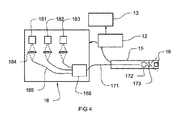
図4を参照すると、一態様では、光源は、複数のコヒーレント光線を発するように動作可能である。これらのコヒーレント光線は、それぞれ異なる色からなり、例えば限定するものではないが青、緑、および赤などの原色セットを形成する(RGBシステム、他のシステムも使用され得る)。これを目的として、光源18は、それぞれが異なる色(光波長)を発する例えば種々のLEDなどの複数のコヒーレント光源181、182、183を備えることが可能である。有利には、複数の光源のそれぞれが、同一のDOE173に対して結合される。各コヒーレント光源181〜183は、遠位端部に位置するDOE173まで光線を運び得る光ファイバ185に対して送られる前に光線を平行化するためのコリメートレンズ184などの適切な光学系を備え得る。DOE173における回折角度が波長に依存することにより、コヒーレント光線を使用する1つの利点は、各コヒーレント光線が個別の投影(回折)角度で同一のDOE173によって回折される点である。例として、DE-220回折光学素子(Holoeye、ベルリン)は、19°の角度にて450nmの光線を、23°の角度にて532nmの光線を、および28°にて650nmの光線を投影する。光パターンプロジェクタから100mmの距離の位置に、DE-220DOEにより形成され450nm光線で取得される対称パターンは、70mmのサイズ(直径)を有し、532nm光線で取得されるパターンは、85mmのサイズを有し、650nm光線のパターンは、110mmのサイズを有する。
With reference to FIG. 4, in one aspect, the light source can behave to emit a plurality of coherent rays. Each of these coherent rays consists of different colors and forms a set of primary colors such as, but not limited to, blue, green, and red (RGB systems, other systems may also be used). For this purpose, the
図10は、パターンとしての円形の場合に取得され得るような独立同心パターンのセット200の一例を示す。最内パターン201は、最小投影角度を有する色の光線により得られるパターンである(例えば上記の例では450nm)。最外パターン203は、最大投影角度を有する色の光線により得られ(例えば上記の例では650nm)、中間パターン202は、例えば上記の例では532nmの光線を有して実現される。有利には、より小さなパターンはより大きなパターン内に完全に収容される点が理解できる。言うまでもないが、他の種類のパターンも可能である。したがって、コヒーレント光線は、標的部位に離間光パターンを形成する。これらの光パターンは、同一の形状を有してもよいが、例えば円の場合などにはそれぞれ異なるサイズを有し、各色光線が、投影(回折)角度の相違により標的部位にて個別の直径の円として投影される。これらの円形は、有利には同心状である。同心パターンの生成は、追加の空間を必要としない利点を有する。波長がより短い程、パターンはより小さくなる。それぞれ異なる色の複数の同心パターンを使用することは、調査中の管腔サイズに最も良く合致するパターンを測定のために容易に選択することが可能となるという利点を有する。標的部位にて、ユーザは、種々のコヒーレント光線の中から測定対象の腔部特徴に最も良く合致する光線を選択することができる。
FIG. 10 shows an example of a set of 200 independent concentric patterns that can be obtained in the case of a circle as a pattern. The
したがって、有利には、本明細書において説明される態様のデバイスを用いてなされる測定は、複数の独立パターンの中の1つのみに依拠し、すなわち単色のみの波長を用いて取得されるパターンに依拠する。標的部位における少なくとも2つの、場合によってはさらに多数の位置が、複数のパターンの中の1つから取得されたデータに基づき判定され得る。有利には、コントローラは、これらの位置のみに基づいて直径などの測定値を判定するように構成される。上記のことが、個々のパターンのそれぞれに対して、すなわち複数の光線のそれぞれに対して繰り返され得る。したがって、有利には、本デバイスによりなされる各測定は、1つの光線色との1対1の重ね合わせにおけるものである。その結果、標的部位における同一特徴部に関連し得る測定値が、および種々のパターンにより得られるこれらの測定値であるためそれぞれ異なる精度を有し得る測定値が取得される。 Thus, advantageously, measurements made using the devices of the embodiments described herein rely on only one of a plurality of independent patterns, i.e., patterns obtained using wavelengths of monochromatic only. Rely on. At least two, and in some cases even more, positions at the target site can be determined based on data obtained from one of the patterns. Advantageously, the controller is configured to determine measurements such as diameter based solely on these positions. The above can be repeated for each of the individual patterns, i.e. for each of the plurality of rays. Therefore, advantageously, each measurement made by the device is in a one-to-one superposition with one ray color. As a result, the measured values that may be related to the same feature portion at the target site and those measured values obtained by various patterns are obtained, so that the measured values that can have different accuracy are obtained.
1つの代替形態では、種々の色の光線が、プローブ11に対して連続的に印加される。別の代替例では、ビームコンバイナ186が、例えば光ファイバ171などの単一の導波路へとコヒーレント光線を結合するために複数のコヒーレント光源181〜183に対して結合される。これにより、それぞれ異なる色の光線に対応する光パターンを同時に投影することが可能となる。
In one alternative form, light rays of various colors are continuously applied to the
再び図1を参照すると、ユーザインターフェース121が用意され、コントローラ12に対して結合され得る。有利には、このユーザインターフェースは、オペレータが、種々の色の光線からいずれの光線を投影するかを選択することを可能にするように構成される。例として、ユーザインターフェース121は、これを目的として制御ノブ122を備え得る。具体的なパターン選択は、測定対象である構造体の実サイズおよび/または所望の精度に応じて決定され得る。
With reference to FIG. 1 again, the
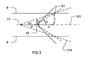
図3を参照すると、例えば気管支の壁部など、気道などの内部通路の壁部8の測定の一例が示される。光パターンプロジェクタ17は、投影角度α(所与の波長に対する)を有し、撮像システム16は、焦点距離fx(ピクセル)により決定される視界(FOV)を有し、パターンは、角度βをなす標的位置81において壁部8上で検出される。撮像システムと光パターンプロジェクタとの間の距離は、dであり、測定深度(光学軸161に沿った撮像システムと測定点81との間の距離)は、zである。通路の径は、rであり、r0は、撮像システム16の位置における光パターンFOVの径である。以下のことが容易に証明され得る。
With reference to FIG. 3, an example of measurement of a
![]()
![]()
深さ(z)は、以下の式により求められる。 The depth (z) is calculated by the following formula.

上記において、pxは、検出される点のピクセル位置である。上記の等式は、所与の面に関するものであり、長手方向軸を中心とする各面に対して有効である。 In the above, p x is the pixel position of the point being detected. The above equation relates to a given plane and is valid for each plane centered on the longitudinal axis.
以下において、所与の投影角度αに関する測定精度は、チャネルのサイズ(径r)に応じて決定されることが証明され得る。深度エラーδzは、以下の式により求められる。 In the following, it can be proved that the measurement accuracy for a given projection angle α depends on the size (diameter r) of the channel. The depth error δz is calculated by the following formula.
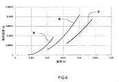
図5は、深さzに対するエラーδzのグラフを示す。これは、DOE DE-R 220(Holoeye、ベルリン)を使用した、3つの異なる光波長ごとの深さに関するデバイスの測定精度を表す。 FIG. 5 shows a graph of error δz for depth z. This represents the measurement accuracy of the device using the DOE DE-R 220 (Holoeye, Berlin) with respect to the depth for each of the three different wavelengths of light.
直径測定の場合に、深さはあまり重要ではない。径(r)に関するエラーδrは以下の式により求められることが証明され得る。 For diameter measurements, depth is not very important. It can be proved that the error δr regarding the diameter (r) can be obtained by the following equation.
図6では、径のエラーδrは、管腔直径に対する直径誤差としてグラフに示される。図5および図6は共にサブミリメートル精度が達成可能であることを示す。精度を上昇させるために、より長い波長の光を使用することが可能である。しかし、これにより、撮像エリア(カメラFOV)と標的部位に投影されるパターンとの間の重畳が無くなり得るため、結果として小さな管腔内では視認不能となり得るより大きなパターンが得られる。小さな管腔においては(または小さな特徴部を測定する場合には)、小さなパターンを使用して測定を行うことが有利である。図6に示すように、所与の直径に対して、絶対誤差は、波長が長くなるとともに低下する。所与の波長に対して、絶対誤差は、直径と共に指数関数的に上昇する。これらのグラフから、より長い波長がより大きな直径に対してより高い精度の測定をもたらすことが演繹され得る。とりわけより大きな波長がより大きな角度で回折され、結果として得られるパターンが過大となり、評定構造体の境界範囲外へと外れてしまう場合があることから、有利には、より短い波長はより小さな直径に対して使用される。気管支のサイズを判定する特定の例では、赤色光(より長い波長)で形成されるパターンは、過大となる場合があり、したがって気管支内のカメラ視野から隠されてしまう場合がある。かかる例では、オペレータまたはシステム自体のいずれかが、例えば青色光(より短い波長)などの異なる色のパターンへと切り替わることにより、結果としてカメラによる視認が可能となり得るより小さなパターンが得られ得る。気管支サイズが大きな例では、赤色光パターンおよび青色光パターンの両者が視認可能となる。しかし、赤色光パターンに基づき行われる測定は、より良好な精度を有する。したがって、デバイスは、この例では赤色光パターンを使用するように設定され得る。 In FIG. 6, the diameter error δr is shown graphically as a diameter error relative to the lumen diameter. Both Figures 5 and 6 show that submillimeter accuracy is achievable. It is possible to use light of longer wavelengths to increase accuracy. However, this can eliminate the superposition between the imaging area (camera FOV) and the pattern projected onto the target site, resulting in a larger pattern that can be invisible within a small lumen. In small lumens (or when measuring small features), it is advantageous to make measurements using small patterns. As shown in FIG. 6, for a given diameter, the absolute error decreases with increasing wavelength. For a given wavelength, the absolute error increases exponentially with diameter. From these graphs it can be deduced that longer wavelengths result in more accurate measurements for larger diameters. Advantageously, shorter wavelengths have smaller diameters, especially since larger wavelengths are diffracted at larger angles, resulting in an oversized pattern that can be out of the bounding range of the rating structure. Used for. In certain examples of determining bronchial size, the pattern formed by red light (longer wavelength) can be excessive and therefore hidden from the camera's field of view within the bronchi. In such an example, either the operator or the system itself may switch to a pattern of a different color, for example blue light (shorter wavelength), resulting in a smaller pattern that may be visible to the camera. In the case of a large bronchial size, both the red light pattern and the blue light pattern are visible. However, measurements made based on the red light pattern have better accuracy. Therefore, the device can be configured to use the red light pattern in this example.
代替的には、空間要件が許す限りにおいて、光パターンプロジェクタ17および撮像システム16を同一軸上に整列させる代わりに、並置および離間位置に置くように位置決めすることが可能である。かかる例では、例えば直線などの線形パターン、または直線に沿って整列された複数のドットもしくはマーカを投影することが有利である場合がある。DOE173は、赤色光、緑色光、および青色光などのそれぞれ異なる波長をそれぞれ異なる投影角度で回折させ、平行パターンのライン間の間隔は、それぞれ異なる光波長ごとに異なる。かかる構成は、例えば真声帯を測定する場合などに有用であり得る。
Alternatively, as spatial requirements allow, the
撮像センサ(CCDまたはCMOS)は、典型的に感光性素子の平面マトリクスを有する単一のチップであることが知られている。各素子に対して入射する光のエネルギーは、センサから出力される信号電荷へと変換される。しかし、この電荷は、ある特定の感光性素子上に入射した光の強度のみを表し、色画像を生成しない。色画像を生成するためには、一般的に、デジタル撮像システムは、典型的には赤、緑、および青(RGB)などの3つの原色バンドルで入射光を調べるフィルタリング方式を採用する。色画像を生成するためにデジタル撮像システムを調整する2つの可能な方法が基本的に存在する。第1の可能性では、感光性素子のそれぞれが、広帯域スペクトル感受性を有する。協働するフィルタディスクが、反復時間シーケンスで、例えば赤色フィルタ、緑色フィルタ、および青色フィルタなどの一連のカラーフィルタを光線に通過させる。フィルタ介入は、画像スキャニングと同期され、フィルタは、典型的には全フィールドスキャン中に介入する。このように動作するデバイスは、「フィールド順次」色信号を生成すると呼ばれる。フィルタディスクは、例えば光が標的部位に対して発せられる前など、光プロジェクタ側か、または例えば光が感光性素子に入社する前など、撮像システム側かのいずれかに配置され得る。代替的な可能性において、個別選択的透過性フィルタのモザイクが、1対1の重ね合わせにおいて個々の感光性素子と重畳される。隣接する感光性素子は、個別の原色を選択的に透過させるフィルタに重畳している。したがって、これらの隣接する感光性素子により取得された信号電荷は、個別の原色を表す。次いで、画像は、ピクセル位置周辺の付近の素子にて検出された色の強度を利用して画像の各ピクセルごとに色を補間することによりデジタル再構成される。かかる補間アルゴリズムは、デモザイク処理アルゴリズムと呼ばれる。かかるモザイクフィルタの1つの既知のタイプが、ベイヤーフィルタ(Bayer filter)であり、1976年7月20日にBayerに付与された特許文献2においてさらに詳細に説明されている。 An imaging sensor (CCD or CMOS) is known to be typically a single chip with a planar matrix of photosensitive elements. The energy of light incident on each element is converted into a signal charge output from the sensor. However, this charge represents only the intensity of light incident on a particular photosensitive element and does not produce a color image. To generate color images, digital imaging systems typically employ a filtering method that examines incident light in three primary color bundles, such as red, green, and blue (RGB). There are basically two possible ways to tune a digital imaging system to produce a color image. In the first possibility, each of the photosensitive devices has wideband spectral sensitivity. Collaborative filter discs pass a series of color filters, such as a red filter, a green filter, and a blue filter, through a ray in an iterative time sequence. The filter intervention is synchronized with image scanning and the filter typically intervenes during the full field scan. Devices that operate in this way are referred to as producing "field-sequential" color signals. The filter disk can be placed either on the optical projector side, for example before the light is emitted to the target site, or on the imaging system side, for example, before the light enters the photosensitive element. In an alternative possibility, a mosaic of individually selective transmissive filters is superimposed on the individual photosensitive elements in a one-to-one superposition. Adjacent photosensitive elements are superimposed on a filter that selectively transmits individual primary colors. Therefore, the signal charges acquired by these adjacent photosensitive elements represent the individual primary colors. The image is then digitally reconstructed by interpolating the color for each pixel of the image using the color intensity detected by the elements near the pixel position. Such an interpolation algorithm is called a demosaic processing algorithm. One known type of such mosaic filter is the Bayer filter, which is described in more detail in Patent Document 2 granted to Bayer on July 20, 1976.
デジタル撮像システムにおいて採用されるフィルタリング方式に関わらず、有利には、撮像センサは、限定するものではないが例えば赤チャネル、緑チャネル、および青チャネルなどのそれぞれ異なるチャネルにおいてなど、標的部位により反射された光の個別のスペクトル領域に関連する信号電化を個別に取得する。個々のチャネルは、所望の色画像を生成するためのデモザイク処理アルゴリズムと共に実装され得る処理ユニット12に対して取得のために結合される。
Regardless of the filtering method adopted in the digital imaging system, the imaging sensor is advantageously reflected by the target site, such as, but not limited to, in different channels such as the red channel, the green channel, and the blue channel. The signal electrification associated with the individual spectral regions of the emitted light is acquired individually. The individual channels are combined for acquisition against a
本発明の一態様では、光パターンプロジェクタ17により投影されたコヒーレント光線は、例えば撮像システム16の個別のチャネルを介してなど個々の信号において個別に取得される。例として、コヒーレント光源181〜183は、例えば赤、緑、および青などの原色など、撮像センサのそれぞれ異なるチャネルの領域に対応する波長領域において光を発するように構成される。有利には、処理ユニット12は、光パターンプロジェクタ17により発せられたそれぞれのコヒーレント光線に対応する色信号を相互に別個に処理するように実装される。そうすることにより、個別の光パターンを検出するための画像セグメンテーションが、大幅に単純化される。結果として、光パターン再構成が、より確実な測定を結果としてもたらすロバスト性のより高いものとなる。
In one aspect of the invention, the coherent rays projected by the
3つ以上のチャネルをさらに採用した他の適切な色(スペクトル)方式を適用し得ることを指摘しておくことが有益だろう。適用可能なフィルタリング方式は、可視光に限定されない。例として、光パターンプロジェクタ17は、赤外線スペクトル領域、具体的には近赤外スペクトル帯の光を発するように構成され得る。有利には、標的部位8により反射される光パターンのそれぞれが、他の光線により発せられた光からの干渉をまったくまたは有意には伴わずに、独立した(色)信号として取得される。
It would be useful to point out that other suitable color (spectral) schemes that further employ three or more channels can be applied. Applicable filtering methods are not limited to visible light. As an example, the
これに関して、コヒーレント光線のスペクトル領域が、撮像センサの1つのみのチャネルによりキャプチャされることは必要ではない。例として、黄色パターン(588nm)が、RGB撮像センサの緑チャネルおよび赤チャネルにより同時にキャプチャされ、青チャネル上には存在しない。 In this regard, it is not necessary that the spectral region of the coherent ray be captured by only one channel of the imaging sensor. As an example, the yellow pattern (588 nm) is captured simultaneously by the green and red channels of the RGB imaging sensor and is not present on the blue channel.
有利には、コントローラ12は、撮像システム16により取得されたデータを処理するように構成される。既に示唆したように、撮像システム16のセンサは、それぞれ異なる色チャネルを備えてもよく、かかる各色チャネルからのデータは、コントローラ12により個別に取得され得る。コントローラ12は、各色チャネルのデータを個別に処理するように構成され得る。複数の色チャネルがそれぞれ、異なる色に関する光パターンを取得し得る。これらの光パターンは、識別できるものであってもよく、すなわち各パターンは、光パターンプロジェクタ17/光源18のそれぞれ異なる光波長により生成される。代替的にはまたは追加的には、これらの色チャネルのいくつか(しかしすべてではない)が、同一の光パターンに関するデータを取得してもよく、例えば光パターンは、撮像システムセンサの2つの(または場合によってはそれ以上の)色チャネルによりキャプチャされる光波長において投影される。コントローラ12は、光パターンを検出するための適切なアルゴリズムと共に実装され得る。例として、例えばOpenCVライブラリから入手可能なものなどのバックグラウンド除去法が、パターンを容易に検出するために使用され得る。RGB色チャネルの例では、および黄色光波長を有する光パターンが使用される場合には、赤チャネルおよび緑チャネルが合併され、青チャネルから除去され得る。
Advantageously, the
コントローラ12は、取得された光パターンの少なくとも1つおよび有利にはそれぞれに関して、または代替的にはその光パターンが取得した色チャネルのそれぞれに関して、標的部位における2点間の(距離)測定値を判定するように構成され得る。有利には、これらの個々の測定値は、標的部位に位置するまったく同一の特徴部に関するものである。判定された距離または測定値に基づき、コントローラ12は、最低の測定誤差を有する距離を判定するように構成され得る。上記に示唆したように、所与の距離に関する測定誤差は、光パターンの波長に依存し、コントローラは、使用されるいずれの波長が結果的に最高の精度をもたらすかを容易に確認することが可能である。これは、例えばコントローラ12内に備えられる可読メモリ内にルックアップテーブルを格納することになどによって達成され得る。ルックアップテーブルは、所与の距離測定値に関連する測定誤差を各波長ごとに含み得る。この例では、コントローラ12は、所与の距離に関するルックアップテーブルのエントリを比較するように構成され得る。
コントローラ12は、撮像されたパターンに沿った点の三次元座標を判定するように構成され得る。円形点の座標を有する円などの回転対称パターンの場合には、コントローラは、平均直径、最小直径、または最大直径の中の1つまたは複数などの、1つまたは複数の直径を計算するように構成され得る。かかる測定が、撮像される各パターンごとに、具体的には各光波長ごとに繰り返され得る。直径などの測定値は、表示装置13で視覚化され得る。
The
有利には、これらのパターンは、可視範囲内の光波長からなる。1つの利点は、オペレータが、そのパターンが測定対象の所望の標的構造体上に位置決めされているか否かに関するフィードバックを即座に受領する点である。表示装置13上のインジケータで測定点を位置決めするのではなく、オペレータは、プローブ11を位置決めすることによって標的構造体上で直接的にパターンを位置決めする。
Advantageously, these patterns consist of light wavelengths within the visible range. One advantage is that the operator immediately receives feedback as to whether the pattern is positioned on the desired target structure to be measured. Rather than positioning the measurement point with an indicator on the
種々の波長の光パターンを連続的に投影することが可能であってもよい。コントローラは、例えば最長または最短の光波長に対応する第1の光パターンで開始し、その後に望ましい精度を有する測定値が得られるまで光波長を変更するように構成され得る。例として、標的構造体が小さい場合に、より長い波長の光パターン(例えば赤色)を投影することにより、標的構造体に干渉しないパターン(過大であるため)が結果的に得られ得る。かかる例では、コントローラは、投影された光パターンのサイズ(および色)を変更する投影光波長を変更するように構成され得る。これは、例えば測定値がまったく検出できない場合にコントローラが波長を変更するなど自動的に、または例えば投影波長の変更をオペレータが行い得るプッシュボタンを用いてなど手動的にのいずれかによって実行され得る。これらの例において、ある光波長に対応する1つの光パターンが、1回に投影され得る。 It may be possible to continuously project light patterns of various wavelengths. The controller may be configured to start with, for example, a first light pattern corresponding to the longest or shortest light wavelength and then change the light wavelength until a measurement with the desired accuracy is obtained. As an example, when the target structure is small, projecting a light pattern with a longer wavelength (eg, red) can result in a pattern that does not interfere with the target structure (because it is excessive). In such an example, the controller may be configured to change the projected light wavelength, which changes the size (and color) of the projected light pattern. This can be done either automatically, for example if the controller changes the wavelength if no measurements are detected, or manually, for example using a push button that allows the operator to change the projected wavelength. .. In these examples, one light pattern corresponding to a certain light wavelength can be projected at one time.
例として、気管支の直径測定が、好ましくは円形パターンを使用して実施される。このパターンは、管腔に合致するように位置決めされ、パターンの像が、記録されコントローラへ送られる。パターンは、自動的に三次元で再構成され、直径は、既知の技術により判定され得る。プローブが気管支管腔内において中心に位置していない場合には、パターンの三次元再構成は、光学軸に対して傾斜する。この傾斜は、コントローラにより検出されることが可能であり、ユーザ/オペレータに対して警告信号を発するように、または測定値を自動補正するように構成されてもよい。別の可能性は、複数の異なるパターンを組み合わせることである。この例では、種々のパターンの三次元再構成は、管腔の追加情報を提供し、確実な直径測定値を獲得するために必要なすべてのデータを提供してもよい。解剖学的構造体が非円形形状である場合には、複数の測定値が、そのパターン(再構成)を介して取得されてもよく、表面、最大直径、最小直径、または取得可能な任意の幾何学的データなどのこれらの測定値のすべてが、視覚的表示装置上に表示され得る。 As an example, bronchial diameter measurements are preferably performed using a circular pattern. The pattern is positioned to match the lumen and an image of the pattern is recorded and sent to the controller. The pattern is automatically reconstructed in three dimensions and the diameter can be determined by known techniques. If the probe is not centrally located within the bronchial lumen, the three-dimensional reconstruction of the pattern is tilted with respect to the optic axis. This tilt can be detected by the controller and may be configured to signal a warning signal to the user / operator or to automatically correct the measurements. Another possibility is to combine several different patterns. In this example, the three-dimensional reconstruction of the various patterns may provide additional information on the lumen and provide all the data needed to obtain reliable diameter measurements. If the anatomical structure is non-circular, multiple measurements may be obtained via its pattern (reconstruction), surface, maximum diameter, minimum diameter, or any available. All of these measurements, such as geometric data, can be displayed on a visual display device.
測定対象の構造体の輪郭が、例えば奇形などにより変則的である場合には、最小外接円および最大封入円などの幾何学量が、自動認識/再構成されたパターンに基づきコントローラ12により判定され得る。
When the contour of the structure to be measured is irregular due to malformation, for example, geometrical quantities such as the minimum circumscribed circle and the maximum enclosed circle are determined by the
したがって、有利には、コントローラ12は、パターンおよび/またはパターン上の測定点を自動認識することを可能にする適切なソフトウェアおよび/またはハードウェアを備える。さらに、有利には、コントローラ12は、自動認識されたパターンおよび/または測定点から測定値を自動判定することを可能にする適切なソフトウェアを備える。有利には、測定値は、直径、周長、距離、または面積を表す数値である。有利には、パターンは、例えば完全な円、または円上の位置する線セグメントまたは点などの円形形状を有する。有利には、かかる形状により、測定することが望まれる位置の上へのオペレータによるパターンの容易な位置決めが可能となり、さらに容易な自動認識および/または測定値計算が可能となる。
Therefore, advantageously, the
有利には、コントローラは、同一パターンまたはそれぞれ異なる色の独立パターンのいずれかを用いて連続測定を実施するように構成される。例えば一定時間間隔をおいた同一パターンによる連続測定を行うことは、内腔の輪郭測定または平均値算出にとって有用であり得る。それぞれ異なる色のパターンがそれぞれ異なるサイズを有することにより、同一標的サイズにおけるこれらのパターンを用いた連続測定を行うことは、例えば狭窄部などに位置する標的サイズの種々の構造体の平均値算出または測定にとって有用であり、最大パターンは、遮断されない有効口径のサイズを測定し、最小パターンは、遮断物すなわち遮断された有効口径のサイズを測定し得る。 Advantageously, the controller is configured to perform continuous measurements using either the same pattern or independent patterns of different colors. For example, continuous measurement with the same pattern at regular time intervals may be useful for measuring the contour of the lumen or calculating the average value. Since the patterns of different colors have different sizes, continuous measurement using these patterns at the same target size can be performed by calculating the average value of various structures of the target size located in a constriction, for example. Useful for measurement, the maximum pattern can measure the size of the effective caliber that is not blocked, and the minimum pattern can measure the size of the blocker or effective caliber that is blocked.
有利には、光パターンプロジェクタ17は、光パターンの方向を調節するために屈折を利用するための追加の光学素子、具体的には光屈折媒体を備え得る。図7を参照すると、光屈折媒体176は、DOE173の下流に配置され得る。光線は、最初にDOE173を利用して回折され、別の有利な方向に屈折される。光屈折媒体176およびDOE173の両者の組合せにより、投影角度がもたらされる。光屈折の利用により、最終的なより小さな投影角度を得ることが可能となり、したがってより小さな要素を測定することが可能となる。図7では、より小さな要素を測定するためにテレセントリックパターン177(深度方向に一定サイズの)を発生させるように、形状が最適化される。
Advantageously, the
上記の任意のものに加えて、図8を参照すると、プローブは、ハウジング15の外方表面上に目盛152を備え得る。これらの目盛152は、ハウジング15の長手方向軸151に沿って配置されてもよく、プローブが挿入された深度を内視鏡医が判定するのを可能にする。これにより、例えば狭窄部の長さなどを分析することが可能となり得る。測定は、別の内視鏡を使用して(例えばデバイスが器具チャネルに挿通される場合)、またはユーザが患者内のプローブを移動させる場合には患者外部において直接行うことも可能である。
In addition to any of the above, referring to FIG. 8, the probe may have a
目盛152は、ハウジング15の移動距離を自動測定するための電子エンコーダ(例えば光学エンコーダ)であることが可能である。エンコーダの読取りは、光パターンに基づく測定値(直径、面積、外周)との重ね合わせにおいて行われ得る。これは、例えば管腔の収縮部が延在する距離を判定するためなどにおいて有用であり得る。これを目的として、電子エンコーダは、測定の実施との重ね合わせにおいて移動距離を読み取るためにコントローラ12に対して結合された出力部を有し得る。
The
有利には、光パターンプロジェクタ17は、場合によってはそれぞれ異なる色のコヒーレント光線の使用によりそれぞれの色が異なる例えば1つまたは複数の線、あるいは1つまたは複数の基準光成分などの、光パターンを発生させるように構成される。1つまたは複数の基準成分は、異なる色のそれぞれに対して生成され得る。
Advantageously, the
基準光成分は、標的部位の表面上に基準マーカを形成するように構成される。有利には、基準マーカは、例えばコントローラ12に対して結合された視覚的表示装置13上などにおいてオペレータにより認識可能となるように形状設定される。したがって、スコープ器具9を操縦するオペレータは、スコープ器具9の適切な操縦のみにより標的部位8上の関心位置の上に基準マーカを位置決めすることが可能となる。
The reference light component is configured to form a reference marker on the surface of the target site. Advantageously, the reference marker is shaped so that it can be recognized by the operator, for example, on a
いくつかの例では、例えば2つの解剖学的ポイント間などの距離測定値の判定のみを行う代わりに、全三次元表面を測定することが有用であり得る。この例では、有利には、複数の光源が連続的にオンに切り替えられる。これにより、例えば管腔に沿ったスキャンが可能となる。さらに、これらの光源のいくつかが共にオンに切り替えられることもまた可能である。この例では、有利には、3つ以上の光源が使用される。 In some examples, it may be useful to measure the entire three-dimensional surface instead of only determining distance measurements, such as between two anatomical points. In this example, it is advantageous to have multiple light sources switched on in succession. This allows, for example, a scan along the lumen. In addition, it is also possible that some of these light sources can be turned on together. In this example, advantageously three or more light sources are used.
デバイス10は、照明光源をさらに備えることが可能である。照明光源は、コヒーレントでなくてもよい白色光または少なくとも広帯域光の光源であり得る。この照明光源は、照明光源から発せられた光がDOEを通過するように、DOE173に対して光学結合され得る。別の可能性は、DOEに対して光学結合されないコヒーレント光源を使用することであり、光は、均質照明を実現するためにDOEを使用して回折されない。好ましくは、照明光源は、パターンを発生するために使用された光源18の光波長とは異なる波長帯において発光する。この照明光源およびパターンは、カメラのそれぞれ異なるチャネルによりキャプチャされ得る。例として、光源18が赤色パターンを投影する場合には、照明光源は、青および緑であることが可能である。照明光源は、複数の選択可能な波長で発光するように構成され得る。
The
保護シースが、患者とハウジング15などの任意の再使用可能パーツとを隔離するためにプローブ11上に配置され得る。これにより、プローブは、汚染の危険性を伴わずに容易に再使用することが可能となる。さらに、シースにより、例えば引っ掻きからおよび滅菌に関連する損傷から、プローブの光学特性を保護することが可能となり得る。
A protective sheath may be placed on the
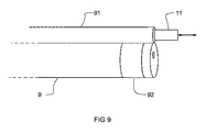
図9を参照すると、従来の内視鏡システムが器具チャネルを有さないかまたは過小な器具チャネルを有する場合に、外部器具チャネル91が内視鏡上に配置され、これを介してプローブ11が移動され得る。この外部器具チャネルは、シースまたはプラスチックリングもしくはシリコーンリング92を介して内視鏡に対して装着され得る。
Referring to FIG. 9, when a conventional endoscopic system has no instrument channel or has an under-instrument channel, an
8 壁部、標的部位
9 内視鏡、スコープ器具
10 非接触測定デバイス
11 プローブ
12 処理ユニット/コントローラ
13 視覚的表示装置
14 ケーブル
15 ハウジング
16 撮像システム
17 光パターンプロジェクタ
18 光源
81 標的位置、測定点
91 外部器具チャネル
111 近位端部
112 遠位端部
121 ユーザインターフェース
122 制御ノブ
151 長手方向軸
152 目盛
161 光学軸
161 測定深度光学軸
171 光ファイバ
172 レンズ
173 回折光学素子、DOE
174 照明場
175 光学軸
176 光屈折媒体
177 テレセントリックパターン
181 コヒーレント光源
182 コヒーレント光源
183 コヒーレント光源
184 コリメートレンズ
185 光ファイバ
186 ビームコンバイナ
200 セット
201 最内パターン
202 中間パターン
203 最外パターン
8 Wall, target area
9 Endoscope, scope instrument
10 Non-contact measuring device
11 probe
12 Processing unit / controller
13 Visual display device
14 cable
15 housing
16 Imaging system
17 Optical pattern projector
18 Light source
81 Target position, measurement point
91 External instrument channel
111 Proximal end
112 Distal end
121 User interface
122 Control knob
151 Longitudinal axis
152 scale
161 optic axis
161 Measurement depth optic axis
171 optical fiber
172 lens
173 Diffractive optics, DOE
174 Lighting area
175 optic axis
176 Photorefractive medium
177 Telecentric pattern
181 Coherent light source
182 Coherent light source
183 Coherent light source
184 Collimating lens
185 Optical fiber
186 Beam combiner
200 sets
201 Innermost pattern
202 intermediate pattern
203 outermost pattern
Claims (19)
光源(18)と、
前記光源に対して光学結合された回折光学素子(173)を備える光パターンプロジェクタ(17)と、
前記光パターンプロジェクタにより照明された標的部位(8)を撮像するように構成された撮像システム(16)と、
前記光パターンプロジェクタおよび前記撮像システムが固定的相対位置において装着された支持部(15)と、
前記撮像システムにより取得されたデータを処理するように構成された処理ユニット(12)と、
を備え、
前記支持部は、前記光パターンプロジェクタ(17)の光学軸(175)に対して平行な長手方向軸(151)を有し、前記光パターンプロジェクタ(17)および前記撮像システム(16)は、前記長手方向軸(151)に沿って離間位置に配置される、デバイス(10)において、
前記光源は、複数のそれぞれ異なる色の光線を発するように動作可能であり、前記複数の光線のそれぞれは、コヒーレント光線であり、前記回折光学素子が個々の回折角度にしたがって前記複数の光線を回折することにより結果として独立パターン(201、202、203)をもたらすように構成されるように、前記回折光学素子(173)に対して光学結合されることと、
前記処理ユニットは、前記独立パターン(201、202、203)の中の1つから取得したデータにおいて自動認識された少なくとも2つの位置に基づき測定値を判定するように構成されることと、
を特徴とする、デバイス。 A device (10) for non-contact measurement,
Light source (18) and
An optical pattern projector (17) including a diffractive optical element (173) optically coupled to the light source,
An imaging system (16) configured to image a target site (8) illuminated by the optical pattern projector, and an imaging system (16).
A support (15) to which the optical pattern projector and the imaging system are mounted in a fixed relative position,
A processing unit (12) configured to process the data acquired by the imaging system, and
With
The support portion has a longitudinal axis (151) parallel to the optical axis (175) of the optical pattern projector (17), and the optical pattern projector (17) and the imaging system (16) have the same. In the device (10), which is located at a distance along the longitudinal axis (151).
The light source can operate to emit a plurality of light rays of different colors, each of the plurality of light rays is a coherent light ray, and the diffracting optical element diffracts the plurality of light rays according to individual diffraction angles. It is optically coupled to the diffractive optical element (173) so as to result in an independent pattern (201, 202, 203).
The processing unit is configured to determine the measured value based on at least two positions automatically recognized in the data acquired from one of the independent patterns (201, 202, 203).
A device that features.
Applications Claiming Priority (3)
| Application Number | Priority Date | Filing Date | Title |
|---|---|---|---|
| EP18151091.8 | 2018-01-10 | ||
| EP18151091.8A EP3510925A1 (en) | 2018-01-10 | 2018-01-10 | Endoscopic non-contact measurement device |
| PCT/EP2019/050418 WO2019137946A1 (en) | 2018-01-10 | 2019-01-09 | Endoscopic non-contact measurement device |
Publications (2)
| Publication Number | Publication Date |
|---|---|
| JP2021510337A true JP2021510337A (en) | 2021-04-22 |
| JPWO2019137946A5 JPWO2019137946A5 (en) | 2022-01-14 |
Family
ID=60954910
Family Applications (1)
| Application Number | Title | Priority Date | Filing Date |
|---|---|---|---|
| JP2020538683A Ceased JP2021510337A (en) | 2018-01-10 | 2019-01-09 | Endoscopic non-contact measuring device |
Country Status (10)
| Country | Link |
|---|---|
| US (1) | US20210068708A1 (en) |
| EP (2) | EP3510925A1 (en) |
| JP (1) | JP2021510337A (en) |
| KR (1) | KR20200107944A (en) |
| CN (1) | CN111511282A (en) |
| AU (1) | AU2019207675A1 (en) |
| CA (1) | CA3086089A1 (en) |
| ES (1) | ES2958883T3 (en) |
| IL (1) | IL275646B2 (en) |
| WO (1) | WO2019137946A1 (en) |
Cited By (1)
| Publication number | Priority date | Publication date | Assignee | Title |
|---|---|---|---|---|
| JP2022548415A (en) * | 2019-11-15 | 2022-11-18 | ルフトハンザ・テッヒニク・アクチェンゲゼルシャフト | Borescope with pattern projector |
Families Citing this family (1)
| Publication number | Priority date | Publication date | Assignee | Title |
|---|---|---|---|---|
| WO2022209156A1 (en) * | 2021-03-30 | 2022-10-06 | ソニーグループ株式会社 | Medical observation device, information processing device, medical observation method, and endoscopic surgery system |
Citations (5)
| Publication number | Priority date | Publication date | Assignee | Title |
|---|---|---|---|---|
| JP2013506861A (en) * | 2009-09-30 | 2013-02-28 | シーメンス アクチエンゲゼルシヤフト | Endoscope |
| JP2016525377A (en) * | 2013-05-02 | 2016-08-25 | ブイエス メドテック, インコーポレイテッド | System and method for measuring and characterizing the inner surface of a luminal structure |
| JP2017517298A (en) * | 2014-04-25 | 2017-06-29 | コーニンクレッカ フィリップス エヌ ヴェKoninklijke Philips N.V. | Catheter with two optical sensors |
| WO2017125926A2 (en) * | 2016-01-18 | 2017-07-27 | Dentlytec G.P.L. Ltd | Intraoral scanner |
| JP2017527137A (en) * | 2014-05-30 | 2017-09-14 | ゼネラル・エレクトリック・カンパニイ | Remote visual inspection image capture system and method |
Family Cites Families (8)
| Publication number | Priority date | Publication date | Assignee | Title |
|---|---|---|---|---|
| US3971065A (en) | 1975-03-05 | 1976-07-20 | Eastman Kodak Company | Color imaging array |
| US6897966B2 (en) * | 2001-05-25 | 2005-05-24 | Poster-Miller, Inc. | Non-contacting mensuration system |
| EP2498667A4 (en) * | 2009-11-13 | 2017-12-27 | California Institute of Technology | Stereo imaging miniature endoscope with single imaging chip and conjugated multi-bandpass filters |
| US9143699B2 (en) * | 2010-07-13 | 2015-09-22 | Sony Computer Entertainment Inc. | Overlay non-video content on a mobile device |
| JP6091410B2 (en) * | 2013-12-26 | 2017-03-08 | オリンパス株式会社 | Endoscope apparatus operating method and endoscope system |
| KR101850640B1 (en) * | 2014-01-31 | 2018-04-19 | 캐논 유.에스.에이. 인코포레이티드 | Apparatus and methods for color endoscopy |
| US10368720B2 (en) * | 2014-11-20 | 2019-08-06 | The Johns Hopkins University | System for stereo reconstruction from monoscopic endoscope images |
| US11598632B2 (en) * | 2018-04-25 | 2023-03-07 | Dentlytec G.P.L. Ltd. | Properties measurement device |
-
2018
- 2018-01-10 EP EP18151091.8A patent/EP3510925A1/en not_active Withdrawn
-
2019
- 2019-01-09 US US16/960,257 patent/US20210068708A1/en active Pending
- 2019-01-09 WO PCT/EP2019/050418 patent/WO2019137946A1/en unknown
- 2019-01-09 KR KR1020207018524A patent/KR20200107944A/en unknown
- 2019-01-09 CN CN201980006798.1A patent/CN111511282A/en active Pending
- 2019-01-09 ES ES19700171T patent/ES2958883T3/en active Active
- 2019-01-09 AU AU2019207675A patent/AU2019207675A1/en active Pending
- 2019-01-09 EP EP19700171.2A patent/EP3737285B1/en active Active
- 2019-01-09 JP JP2020538683A patent/JP2021510337A/en not_active Ceased
- 2019-01-09 CA CA3086089A patent/CA3086089A1/en active Pending
-
2020
- 2020-06-25 IL IL275646A patent/IL275646B2/en unknown
Patent Citations (5)
| Publication number | Priority date | Publication date | Assignee | Title |
|---|---|---|---|---|
| JP2013506861A (en) * | 2009-09-30 | 2013-02-28 | シーメンス アクチエンゲゼルシヤフト | Endoscope |
| JP2016525377A (en) * | 2013-05-02 | 2016-08-25 | ブイエス メドテック, インコーポレイテッド | System and method for measuring and characterizing the inner surface of a luminal structure |
| JP2017517298A (en) * | 2014-04-25 | 2017-06-29 | コーニンクレッカ フィリップス エヌ ヴェKoninklijke Philips N.V. | Catheter with two optical sensors |
| JP2017527137A (en) * | 2014-05-30 | 2017-09-14 | ゼネラル・エレクトリック・カンパニイ | Remote visual inspection image capture system and method |
| WO2017125926A2 (en) * | 2016-01-18 | 2017-07-27 | Dentlytec G.P.L. Ltd | Intraoral scanner |
Cited By (2)
| Publication number | Priority date | Publication date | Assignee | Title |
|---|---|---|---|---|
| JP2022548415A (en) * | 2019-11-15 | 2022-11-18 | ルフトハンザ・テッヒニク・アクチェンゲゼルシャフト | Borescope with pattern projector |
| JP7185807B2 (en) | 2019-11-15 | 2022-12-07 | ルフトハンザ・テッヒニク・アクチェンゲゼルシャフト | Borescope with pattern projector |
Also Published As
| Publication number | Publication date |
|---|---|
| IL275646B2 (en) | 2023-05-01 |
| IL275646B (en) | 2023-01-01 |
| EP3737285B1 (en) | 2023-08-09 |
| WO2019137946A1 (en) | 2019-07-18 |
| EP3737285A1 (en) | 2020-11-18 |
| AU2019207675A1 (en) | 2020-06-25 |
| CN111511282A (en) | 2020-08-07 |
| EP3510925A1 (en) | 2019-07-17 |
| ES2958883T3 (en) | 2024-02-15 |
| US20210068708A1 (en) | 2021-03-11 |
| KR20200107944A (en) | 2020-09-16 |
| IL275646A (en) | 2020-08-31 |
| CA3086089A1 (en) | 2019-07-18 |
| EP3737285C0 (en) | 2023-08-09 |
Similar Documents
| Publication | Publication Date | Title |
|---|---|---|
| US11723758B2 (en) | Intraoral scanning system with visual indicators that facilitate scanning | |
| US20160198982A1 (en) | Endoscope measurement techniques | |
| US20160109226A1 (en) | Chromatic confocal system | |
| JP2018537155A (en) | Apparatus and method for tracking the position of an endoscope within a patient's body | |
| US11160438B2 (en) | Endoscope device and measurement support method | |
| US11419694B2 (en) | Endoscope system measuring size of subject using measurement auxiliary light | |
| CN104520669B (en) | For measuring measurement apparatus, the device and method of measurement object | |
| US10368720B2 (en) | System for stereo reconstruction from monoscopic endoscope images | |
| US11490785B2 (en) | Measurement support device, endoscope system, and processor measuring size of subject using measurement auxiliary light | |
| EP3737285B1 (en) | Endoscopic non-contact measurement device | |
| WO2019182623A1 (en) | Endoscope employing structured light providing physiological feature size measurement | |
| JP6738465B2 (en) | Endoscope system | |
| CN113631076B (en) | Processor device for endoscope, medical image processing device, method for operating medical image processing device, and computer-readable medium | |
| US20130286407A1 (en) | Apparatus | |
| JP2024508315A (en) | Viewing modifications to enhance scene depth estimation |
Legal Events
| Date | Code | Title | Description |
|---|---|---|---|
| A521 | Request for written amendment filed |
Free format text: JAPANESE INTERMEDIATE CODE: A523 Effective date: 20220105 |
|
| A621 | Written request for application examination |
Free format text: JAPANESE INTERMEDIATE CODE: A621 Effective date: 20220105 |
|
| A977 | Report on retrieval |
Free format text: JAPANESE INTERMEDIATE CODE: A971007 Effective date: 20221227 |
|
| A131 | Notification of reasons for refusal |
Free format text: JAPANESE INTERMEDIATE CODE: A131 Effective date: 20230104 |
|
| A521 | Request for written amendment filed |
Free format text: JAPANESE INTERMEDIATE CODE: A523 Effective date: 20230322 |
|
| A01 | Written decision to grant a patent or to grant a registration (utility model) |
Free format text: JAPANESE INTERMEDIATE CODE: A01 Effective date: 20230417 |
|
| A045 | Written measure of dismissal of application [lapsed due to lack of payment] |
Free format text: JAPANESE INTERMEDIATE CODE: A045 Effective date: 20230828 |