JP2021509846A - Retractor with drawstring suture and how to use - Google Patents
Retractor with drawstring suture and how to use Download PDFInfo
- Publication number
- JP2021509846A JP2021509846A JP2020537158A JP2020537158A JP2021509846A JP 2021509846 A JP2021509846 A JP 2021509846A JP 2020537158 A JP2020537158 A JP 2020537158A JP 2020537158 A JP2020537158 A JP 2020537158A JP 2021509846 A JP2021509846 A JP 2021509846A
- Authority
- JP
- Japan
- Prior art keywords
- internal member
- target tissue
- pair
- external members
- shaft
- Prior art date
- Legal status (The legal status is an assumption and is not a legal conclusion. Google has not performed a legal analysis and makes no representation as to the accuracy of the status listed.)
- Pending
Links
- 238000000034 method Methods 0.000 claims abstract description 99
- 230000035515 penetration Effects 0.000 claims abstract description 11
- 210000001519 tissue Anatomy 0.000 claims description 245
- 210000002216 heart Anatomy 0.000 claims description 99
- 210000005246 left atrium Anatomy 0.000 claims description 71
- 230000007246 mechanism Effects 0.000 claims description 69
- 238000001356 surgical procedure Methods 0.000 claims description 34
- 238000002271 resection Methods 0.000 claims description 27
- 210000004369 blood Anatomy 0.000 claims description 24
- 239000008280 blood Substances 0.000 claims description 24
- 230000001746 atrial effect Effects 0.000 claims description 21
- 230000008439 repair process Effects 0.000 claims description 18
- 210000001124 body fluid Anatomy 0.000 claims description 12
- 238000010009 beating Methods 0.000 claims description 11
- 239000010839 body fluid Substances 0.000 claims description 11
- 229920001971 elastomer Polymers 0.000 claims description 11
- 239000000806 elastomer Substances 0.000 claims description 11
- 210000004115 mitral valve Anatomy 0.000 claims description 11
- 238000013519 translation Methods 0.000 claims description 11
- 238000012800 visualization Methods 0.000 claims description 11
- 210000000038 chest Anatomy 0.000 claims description 10
- 230000004044 response Effects 0.000 claims description 9
- 239000010935 stainless steel Substances 0.000 claims description 9
- 229910001220 stainless steel Inorganic materials 0.000 claims description 9
- 239000004677 Nylon Substances 0.000 claims description 8
- 239000004743 Polypropylene Substances 0.000 claims description 8
- RTAQQCXQSZGOHL-UHFFFAOYSA-N Titanium Chemical compound [Ti] RTAQQCXQSZGOHL-UHFFFAOYSA-N 0.000 claims description 8
- 229920000122 acrylonitrile butadiene styrene Polymers 0.000 claims description 8
- 239000004676 acrylonitrile butadiene styrene Substances 0.000 claims description 8
- 239000004973 liquid crystal related substance Substances 0.000 claims description 8
- 229910052751 metal Inorganic materials 0.000 claims description 8
- 239000002184 metal Substances 0.000 claims description 8
- 229920001778 nylon Polymers 0.000 claims description 8
- 239000004033 plastic Substances 0.000 claims description 8
- 229920003023 plastic Polymers 0.000 claims description 8
- 239000004417 polycarbonate Substances 0.000 claims description 8
- 229920000515 polycarbonate Polymers 0.000 claims description 8
- -1 polypropylene Polymers 0.000 claims description 8
- 229920001155 polypropylene Polymers 0.000 claims description 8
- 239000004810 polytetrafluoroethylene Substances 0.000 claims description 8
- 229920001343 polytetrafluoroethylene Polymers 0.000 claims description 8
- 210000001562 sternum Anatomy 0.000 claims description 8
- 239000010936 titanium Substances 0.000 claims description 8
- 238000007789 sealing Methods 0.000 claims description 7
- 238000002679 ablation Methods 0.000 claims description 6
- 210000001765 aortic valve Anatomy 0.000 claims description 6
- 210000003698 chordae tendineae Anatomy 0.000 claims description 6
- 230000002526 effect on cardiovascular system Effects 0.000 claims description 6
- 238000002513 implantation Methods 0.000 claims description 6
- 210000003492 pulmonary vein Anatomy 0.000 claims description 6
- 230000000747 cardiac effect Effects 0.000 claims description 5
- 210000001370 mediastinum Anatomy 0.000 claims description 5
- 230000003287 optical effect Effects 0.000 claims description 5
- 210000000614 rib Anatomy 0.000 claims description 5
- 210000000591 tricuspid valve Anatomy 0.000 claims description 5
- 229910001200 Ferrotitanium Inorganic materials 0.000 claims description 4
- 239000012530 fluid Substances 0.000 claims description 4
- 210000003516 pericardium Anatomy 0.000 claims description 4
- 229910000639 Spring steel Inorganic materials 0.000 claims description 3
- 238000001574 biopsy Methods 0.000 claims description 3
- 230000004927 fusion Effects 0.000 claims description 3
- 230000002107 myocardial effect Effects 0.000 claims description 3
- 230000000149 penetrating effect Effects 0.000 claims description 3
- 230000007547 defect Effects 0.000 claims description 2
- 239000002861 polymer material Substances 0.000 claims 2
- 238000005192 partition Methods 0.000 claims 1
- 230000000472 traumatic effect Effects 0.000 claims 1
- 208000027418 Wounds and injury Diseases 0.000 description 39
- 210000000056 organ Anatomy 0.000 description 39
- 238000013459 approach Methods 0.000 description 11
- 239000000463 material Substances 0.000 description 10
- 229920000642 polymer Polymers 0.000 description 10
- 238000009434 installation Methods 0.000 description 9
- 230000033001 locomotion Effects 0.000 description 9
- 238000007796 conventional method Methods 0.000 description 8
- 230000008901 benefit Effects 0.000 description 7
- 230000006378 damage Effects 0.000 description 6
- 230000004048 modification Effects 0.000 description 6
- 238000012986 modification Methods 0.000 description 6
- 208000014674 injury Diseases 0.000 description 5
- 210000003484 anatomy Anatomy 0.000 description 4
- 150000002739 metals Chemical class 0.000 description 4
- 239000007787 solid Substances 0.000 description 4
- 229910052719 titanium Inorganic materials 0.000 description 4
- 230000000740 bleeding effect Effects 0.000 description 3
- 210000000988 bone and bone Anatomy 0.000 description 3
- 210000002837 heart atrium Anatomy 0.000 description 3
- 230000023597 hemostasis Effects 0.000 description 3
- 238000003780 insertion Methods 0.000 description 3
- 230000037431 insertion Effects 0.000 description 3
- 230000037361 pathway Effects 0.000 description 3
- 210000001147 pulmonary artery Anatomy 0.000 description 3
- 210000002784 stomach Anatomy 0.000 description 3
- 210000003437 trachea Anatomy 0.000 description 3
- 210000000683 abdominal cavity Anatomy 0.000 description 2
- 238000003763 carbonization Methods 0.000 description 2
- 230000001627 detrimental effect Effects 0.000 description 2
- 238000002224 dissection Methods 0.000 description 2
- 230000002496 gastric effect Effects 0.000 description 2
- 230000002439 hemostatic effect Effects 0.000 description 2
- 210000004165 myocardium Anatomy 0.000 description 2
- 239000012811 non-conductive material Substances 0.000 description 2
- 230000008569 process Effects 0.000 description 2
- 238000012546 transfer Methods 0.000 description 2
- 208000034693 Laceration Diseases 0.000 description 1
- 208000008589 Obesity Diseases 0.000 description 1
- 241001080929 Zeugopterus punctatus Species 0.000 description 1
- 230000002378 acidificating effect Effects 0.000 description 1
- 210000000709 aorta Anatomy 0.000 description 1
- 210000002376 aorta thoracic Anatomy 0.000 description 1
- 210000000013 bile duct Anatomy 0.000 description 1
- 230000015572 biosynthetic process Effects 0.000 description 1
- 230000036772 blood pressure Effects 0.000 description 1
- 239000003518 caustics Substances 0.000 description 1
- 210000003109 clavicle Anatomy 0.000 description 1
- 210000001072 colon Anatomy 0.000 description 1
- 238000010878 colorectal surgery Methods 0.000 description 1
- 239000004020 conductor Substances 0.000 description 1
- 230000001419 dependent effect Effects 0.000 description 1
- 230000000916 dilatatory effect Effects 0.000 description 1
- 238000010494 dissociation reaction Methods 0.000 description 1
- 230000005593 dissociations Effects 0.000 description 1
- 229920005570 flexible polymer Polymers 0.000 description 1
- 238000002594 fluoroscopy Methods 0.000 description 1
- 210000000232 gallbladder Anatomy 0.000 description 1
- 208000025339 heart septal defect Diseases 0.000 description 1
- 210000005003 heart tissue Anatomy 0.000 description 1
- 239000011810 insulating material Substances 0.000 description 1
- 238000002324 minimally invasive surgery Methods 0.000 description 1
- 210000003739 neck Anatomy 0.000 description 1
- 229910001000 nickel titanium Inorganic materials 0.000 description 1
- HLXZNVUGXRDIFK-UHFFFAOYSA-N nickel titanium Chemical compound [Ti].[Ti].[Ti].[Ti].[Ti].[Ti].[Ti].[Ti].[Ti].[Ti].[Ti].[Ni].[Ni].[Ni].[Ni].[Ni].[Ni].[Ni].[Ni].[Ni].[Ni].[Ni].[Ni].[Ni].[Ni] HLXZNVUGXRDIFK-UHFFFAOYSA-N 0.000 description 1
- 235000020824 obesity Nutrition 0.000 description 1
- 210000003101 oviduct Anatomy 0.000 description 1
- 238000002360 preparation method Methods 0.000 description 1
- 230000002787 reinforcement Effects 0.000 description 1
- 210000000813 small intestine Anatomy 0.000 description 1
- 238000006467 substitution reaction Methods 0.000 description 1
- 210000000115 thoracic cavity Anatomy 0.000 description 1
- 238000013175 transesophageal echocardiography Methods 0.000 description 1
- 238000002054 transplantation Methods 0.000 description 1
- 230000001960 triggered effect Effects 0.000 description 1
- 210000005239 tubule Anatomy 0.000 description 1
- 210000000626 ureter Anatomy 0.000 description 1
- 210000003932 urinary bladder Anatomy 0.000 description 1
- 230000000007 visual effect Effects 0.000 description 1
Images


Classifications
-
- A—HUMAN NECESSITIES
- A61—MEDICAL OR VETERINARY SCIENCE; HYGIENE
- A61B—DIAGNOSIS; SURGERY; IDENTIFICATION
- A61B17/00—Surgical instruments, devices or methods, e.g. tourniquets
- A61B17/0057—Implements for plugging an opening in the wall of a hollow or tubular organ, e.g. for sealing a vessel puncture or closing a cardiac septal defect
-
- A—HUMAN NECESSITIES
- A61—MEDICAL OR VETERINARY SCIENCE; HYGIENE
- A61B—DIAGNOSIS; SURGERY; IDENTIFICATION
- A61B17/00—Surgical instruments, devices or methods, e.g. tourniquets
- A61B17/04—Surgical instruments, devices or methods, e.g. tourniquets for suturing wounds; Holders or packages for needles or suture materials
- A61B17/0469—Suturing instruments for use in minimally invasive surgery, e.g. endoscopic surgery
-
- A—HUMAN NECESSITIES
- A61—MEDICAL OR VETERINARY SCIENCE; HYGIENE
- A61B—DIAGNOSIS; SURGERY; IDENTIFICATION
- A61B17/00—Surgical instruments, devices or methods, e.g. tourniquets
- A61B17/02—Surgical instruments, devices or methods, e.g. tourniquets for holding wounds open; Tractors
-
- A—HUMAN NECESSITIES
- A61—MEDICAL OR VETERINARY SCIENCE; HYGIENE
- A61B—DIAGNOSIS; SURGERY; IDENTIFICATION
- A61B17/00—Surgical instruments, devices or methods, e.g. tourniquets
- A61B17/02—Surgical instruments, devices or methods, e.g. tourniquets for holding wounds open; Tractors
- A61B17/0206—Surgical instruments, devices or methods, e.g. tourniquets for holding wounds open; Tractors with antagonistic arms as supports for retractor elements
-
- A—HUMAN NECESSITIES
- A61—MEDICAL OR VETERINARY SCIENCE; HYGIENE
- A61B—DIAGNOSIS; SURGERY; IDENTIFICATION
- A61B17/00—Surgical instruments, devices or methods, e.g. tourniquets
- A61B17/02—Surgical instruments, devices or methods, e.g. tourniquets for holding wounds open; Tractors
- A61B17/0218—Surgical instruments, devices or methods, e.g. tourniquets for holding wounds open; Tractors for minimally invasive surgery
-
- A—HUMAN NECESSITIES
- A61—MEDICAL OR VETERINARY SCIENCE; HYGIENE
- A61B—DIAGNOSIS; SURGERY; IDENTIFICATION
- A61B17/00—Surgical instruments, devices or methods, e.g. tourniquets
- A61B17/04—Surgical instruments, devices or methods, e.g. tourniquets for suturing wounds; Holders or packages for needles or suture materials
- A61B17/0482—Needle or suture guides
-
- A—HUMAN NECESSITIES
- A61—MEDICAL OR VETERINARY SCIENCE; HYGIENE
- A61B—DIAGNOSIS; SURGERY; IDENTIFICATION
- A61B17/00—Surgical instruments, devices or methods, e.g. tourniquets
- A61B17/04—Surgical instruments, devices or methods, e.g. tourniquets for suturing wounds; Holders or packages for needles or suture materials
- A61B17/06—Needles ; Sutures; Needle-suture combinations; Holders or packages for needles or suture materials
- A61B17/062—Needle manipulators
-
- A—HUMAN NECESSITIES
- A61—MEDICAL OR VETERINARY SCIENCE; HYGIENE
- A61B—DIAGNOSIS; SURGERY; IDENTIFICATION
- A61B17/00—Surgical instruments, devices or methods, e.g. tourniquets
- A61B17/34—Trocars; Puncturing needles
- A61B17/3417—Details of tips or shafts, e.g. grooves, expandable, bendable; Multiple coaxial sliding cannulas, e.g. for dilating
-
- A—HUMAN NECESSITIES
- A61—MEDICAL OR VETERINARY SCIENCE; HYGIENE
- A61B—DIAGNOSIS; SURGERY; IDENTIFICATION
- A61B18/00—Surgical instruments, devices or methods for transferring non-mechanical forms of energy to or from the body
- A61B18/04—Surgical instruments, devices or methods for transferring non-mechanical forms of energy to or from the body by heating
- A61B18/12—Surgical instruments, devices or methods for transferring non-mechanical forms of energy to or from the body by heating by passing a current through the tissue to be heated, e.g. high-frequency current
- A61B18/14—Probes or electrodes therefor
-
- A—HUMAN NECESSITIES
- A61—MEDICAL OR VETERINARY SCIENCE; HYGIENE
- A61B—DIAGNOSIS; SURGERY; IDENTIFICATION
- A61B90/00—Instruments, implements or accessories specially adapted for surgery or diagnosis and not covered by any of the groups A61B1/00 - A61B50/00, e.g. for luxation treatment or for protecting wound edges
- A61B90/02—Devices for expanding tissue, e.g. skin tissue
-
- A—HUMAN NECESSITIES
- A61—MEDICAL OR VETERINARY SCIENCE; HYGIENE
- A61B—DIAGNOSIS; SURGERY; IDENTIFICATION
- A61B17/00—Surgical instruments, devices or methods, e.g. tourniquets
- A61B17/00234—Surgical instruments, devices or methods, e.g. tourniquets for minimally invasive surgery
- A61B2017/00238—Type of minimally invasive operation
- A61B2017/00243—Type of minimally invasive operation cardiac
-
- A—HUMAN NECESSITIES
- A61—MEDICAL OR VETERINARY SCIENCE; HYGIENE
- A61B—DIAGNOSIS; SURGERY; IDENTIFICATION
- A61B17/00—Surgical instruments, devices or methods, e.g. tourniquets
- A61B17/0057—Implements for plugging an opening in the wall of a hollow or tubular organ, e.g. for sealing a vessel puncture or closing a cardiac septal defect
- A61B2017/00575—Implements for plugging an opening in the wall of a hollow or tubular organ, e.g. for sealing a vessel puncture or closing a cardiac septal defect for closure at remote site, e.g. closing atrial septum defects
-
- A—HUMAN NECESSITIES
- A61—MEDICAL OR VETERINARY SCIENCE; HYGIENE
- A61B—DIAGNOSIS; SURGERY; IDENTIFICATION
- A61B17/00—Surgical instruments, devices or methods, e.g. tourniquets
- A61B17/0057—Implements for plugging an opening in the wall of a hollow or tubular organ, e.g. for sealing a vessel puncture or closing a cardiac septal defect
- A61B2017/00637—Implements for plugging an opening in the wall of a hollow or tubular organ, e.g. for sealing a vessel puncture or closing a cardiac septal defect for sealing trocar wounds through abdominal wall
-
- A—HUMAN NECESSITIES
- A61—MEDICAL OR VETERINARY SCIENCE; HYGIENE
- A61B—DIAGNOSIS; SURGERY; IDENTIFICATION
- A61B17/00—Surgical instruments, devices or methods, e.g. tourniquets
- A61B17/0057—Implements for plugging an opening in the wall of a hollow or tubular organ, e.g. for sealing a vessel puncture or closing a cardiac septal defect
- A61B2017/00646—Type of implements
- A61B2017/00663—Type of implements the implement being a suture
-
- A—HUMAN NECESSITIES
- A61—MEDICAL OR VETERINARY SCIENCE; HYGIENE
- A61B—DIAGNOSIS; SURGERY; IDENTIFICATION
- A61B17/00—Surgical instruments, devices or methods, e.g. tourniquets
- A61B17/02—Surgical instruments, devices or methods, e.g. tourniquets for holding wounds open; Tractors
- A61B2017/0237—Surgical instruments, devices or methods, e.g. tourniquets for holding wounds open; Tractors for heart surgery
-
- A—HUMAN NECESSITIES
- A61—MEDICAL OR VETERINARY SCIENCE; HYGIENE
- A61B—DIAGNOSIS; SURGERY; IDENTIFICATION
- A61B17/00—Surgical instruments, devices or methods, e.g. tourniquets
- A61B17/04—Surgical instruments, devices or methods, e.g. tourniquets for suturing wounds; Holders or packages for needles or suture materials
- A61B17/0469—Suturing instruments for use in minimally invasive surgery, e.g. endoscopic surgery
- A61B2017/047—Suturing instruments for use in minimally invasive surgery, e.g. endoscopic surgery having at least one proximally pointing needle located at the distal end of the instrument, e.g. for suturing trocar puncture wounds starting from inside the body
-
- A—HUMAN NECESSITIES
- A61—MEDICAL OR VETERINARY SCIENCE; HYGIENE
- A61B—DIAGNOSIS; SURGERY; IDENTIFICATION
- A61B17/00—Surgical instruments, devices or methods, e.g. tourniquets
- A61B17/04—Surgical instruments, devices or methods, e.g. tourniquets for suturing wounds; Holders or packages for needles or suture materials
- A61B17/0469—Suturing instruments for use in minimally invasive surgery, e.g. endoscopic surgery
- A61B2017/0474—Knot pushers
-
- A—HUMAN NECESSITIES
- A61—MEDICAL OR VETERINARY SCIENCE; HYGIENE
- A61B—DIAGNOSIS; SURGERY; IDENTIFICATION
- A61B17/00—Surgical instruments, devices or methods, e.g. tourniquets
- A61B17/04—Surgical instruments, devices or methods, e.g. tourniquets for suturing wounds; Holders or packages for needles or suture materials
- A61B17/06—Needles ; Sutures; Needle-suture combinations; Holders or packages for needles or suture materials
- A61B17/06066—Needles, e.g. needle tip configurations
- A61B2017/0608—J-shaped
-
- A—HUMAN NECESSITIES
- A61—MEDICAL OR VETERINARY SCIENCE; HYGIENE
- A61B—DIAGNOSIS; SURGERY; IDENTIFICATION
- A61B17/00—Surgical instruments, devices or methods, e.g. tourniquets
- A61B17/11—Surgical instruments, devices or methods, e.g. tourniquets for performing anastomosis; Buttons for anastomosis
- A61B2017/1142—Purse-string sutures
-
- A—HUMAN NECESSITIES
- A61—MEDICAL OR VETERINARY SCIENCE; HYGIENE
- A61B—DIAGNOSIS; SURGERY; IDENTIFICATION
- A61B17/00—Surgical instruments, devices or methods, e.g. tourniquets
- A61B17/34—Trocars; Puncturing needles
- A61B17/3417—Details of tips or shafts, e.g. grooves, expandable, bendable; Multiple coaxial sliding cannulas, e.g. for dilating
- A61B2017/3419—Sealing means between cannula and body
-
- A—HUMAN NECESSITIES
- A61—MEDICAL OR VETERINARY SCIENCE; HYGIENE
- A61B—DIAGNOSIS; SURGERY; IDENTIFICATION
- A61B17/00—Surgical instruments, devices or methods, e.g. tourniquets
- A61B17/34—Trocars; Puncturing needles
- A61B17/3417—Details of tips or shafts, e.g. grooves, expandable, bendable; Multiple coaxial sliding cannulas, e.g. for dilating
- A61B17/3421—Cannulas
- A61B17/3423—Access ports, e.g. toroid shape introducers for instruments or hands
- A61B2017/3425—Access ports, e.g. toroid shape introducers for instruments or hands for internal organs, e.g. heart ports
-
- A—HUMAN NECESSITIES
- A61—MEDICAL OR VETERINARY SCIENCE; HYGIENE
- A61B—DIAGNOSIS; SURGERY; IDENTIFICATION
- A61B18/00—Surgical instruments, devices or methods for transferring non-mechanical forms of energy to or from the body
- A61B2018/00315—Surgical instruments, devices or methods for transferring non-mechanical forms of energy to or from the body for treatment of particular body parts
- A61B2018/00345—Vascular system
- A61B2018/00351—Heart
-
- A—HUMAN NECESSITIES
- A61—MEDICAL OR VETERINARY SCIENCE; HYGIENE
- A61B—DIAGNOSIS; SURGERY; IDENTIFICATION
- A61B18/00—Surgical instruments, devices or methods for transferring non-mechanical forms of energy to or from the body
- A61B2018/00571—Surgical instruments, devices or methods for transferring non-mechanical forms of energy to or from the body for achieving a particular surgical effect
- A61B2018/00595—Cauterization
-
- A—HUMAN NECESSITIES
- A61—MEDICAL OR VETERINARY SCIENCE; HYGIENE
- A61B—DIAGNOSIS; SURGERY; IDENTIFICATION
- A61B18/00—Surgical instruments, devices or methods for transferring non-mechanical forms of energy to or from the body
- A61B18/04—Surgical instruments, devices or methods for transferring non-mechanical forms of energy to or from the body by heating
- A61B18/12—Surgical instruments, devices or methods for transferring non-mechanical forms of energy to or from the body by heating by passing a current through the tissue to be heated, e.g. high-frequency current
- A61B18/14—Probes or electrodes therefor
- A61B2018/1405—Electrodes having a specific shape
- A61B2018/1425—Needle
-
- A—HUMAN NECESSITIES
- A61—MEDICAL OR VETERINARY SCIENCE; HYGIENE
- A61B—DIAGNOSIS; SURGERY; IDENTIFICATION
- A61B2217/00—General characteristics of surgical instruments
- A61B2217/002—Auxiliary appliance
- A61B2217/005—Auxiliary appliance with suction drainage system
Abstract
内視鏡下で標的組織を後退させるためのシステム、デバイス、および方法。本デバイスは、第1のシャフトと、そこに摺動可能に結合される、第2のシャフトとを含む。内部部材が、第1のシャフトから横方向に延在し、標的組織内の穿通部を通して前進し、それを通して前進された後、標的組織の遠位表面に非外傷的に係合するために構成される。一対の外部部材が、横方向と略平行に、第2のシャフトから延在する。外部部材は、離間され、内部部材が外部部材に対して縦方向に移動されると、標的組織の近位表面に非外傷的に係合するように構成される。内部部材は、対の外部部材を越えて後退されると、牽引力を標的組織に印加し、これは、逆牽引力を内部部材の対向する側方側の標的組織に印加し、標的組織を再成形し、後続縫合糸設置を可能にする。Systems, devices, and methods for endoscopically retracting target tissue. The device includes a first shaft and a second shaft slidably coupled thereto. An internal member extends laterally from the first shaft, advances through a penetration within the target tissue, and after being advanced through it, is configured to non-traumatically engage the distal surface of the target tissue. Will be done. A pair of external members extend from the second shaft substantially parallel to the lateral direction. The outer members are spaced apart and configured to non-traumatically engage the proximal surface of the target tissue as the inner member is moved longitudinally with respect to the outer member. When the internal member is retracted beyond the pair of external members, it applies a traction force to the target tissue, which applies a reverse traction force to the opposing lateral target tissue of the internal member to reshape the target tissue. And allows subsequent suture placement.
Description
(関連出願の相互参照)
本願は、その全内容が、参照することによって本明細書に組み込まれる、2018年1月5日に出願され、「PURSESTRING SUTURE RETRACTOR AND METHOD OF USE」(弁理士整理番号54513−704.101(以前は、MRP001))と題された、米国仮出願第62/614,326号の利益を主張する。
(Cross-reference of related applications)
The present application was filed on January 5, 2018, the entire contents of which are incorporated herein by reference, and is "PURRESTRING SUTURE RETRACTOR AND METHOD OF USE" (Patent Attorney Reference No. 54513-704.101 (previously). Claims the interests of US Provisional Application No. 62 / 614,326, entitled MRP001)).
本開示は、概して、外科手術用皮膚切開部の部位から遠隔で中空器官を調製するため、外科手術手技を器官の内側で実施するための器具の進入のため、および外科手術手技の完了に応じた中空器官の閉鎖のためのデバイス、システム、ならびに方法に関する。 The present disclosure generally relies on the preparation of hollow organs remotely from the site of a surgical skin incision, the entry of instruments for performing surgical procedures inside organs, and the completion of surgical procedures. With respect to devices, systems, and methods for closure of hollow organs.
多くの外科手術手技は、一般に、患者の胃または心臓等の中空器官または生物学的構造内で実施される。切開部が、中空器官の外側表面内に設置され、外科手術手技を実施するために必要とされる器具の通路を提供し得る。そのような外科手術手技は、低侵襲性様式において実施されるとき、中空器官の遠隔にあり得る、小皮膚切開部を通して開始され得る。外科手術用器具が、皮膚切開部を通して、患者の身体中に挿入され、その中の切開部を介して、中空器官の中に前進され得る。いったん中空器官に来ると、シールが、外科手術手技の間、中空器官内の切開部と動作可能器具との間に生成されなければならないだけではなく、切開部もまた、手技の完了に応じて、閉鎖され、周囲組織の中への器官の内部内容物の損失を防止しなければならない。例えば、外科手術手技を胃上で実施する間、腹腔の中への苛性の酸性胃内容物の漏出を可能にすることは、有害である。外科手術手技が、心臓の中への進入を伴う場合、心臓アクセス切開部の制御および後続閉鎖は、特に、心室内の正の血圧が出血を生じさせ、無抑制血液損失が生じる場合、患者の死亡につながり得るため、重要であり得る。 Many surgical procedures are generally performed within a hollow organ or biological structure such as the patient's stomach or heart. An incision may be placed within the outer surface of the hollow organ to provide a passage for the instruments needed to perform the surgical procedure. Such surgical procedures, when performed in a minimally invasive manner, can be initiated through a small skin incision that can be remote to the hollow organ. Surgical instruments can be inserted into the patient's body through a skin incision and advanced into a hollow organ through the incision therein. Once in the hollow organ, not only must a seal be created between the incision in the hollow organ and the operable instrument during the surgical procedure, but the incision also depends on the completion of the procedure. It must be closed and prevent loss of the internal contents of the organ into the surrounding tissue. For example, allowing the caustic acidic gastric contents to leak into the abdominal cavity while performing a surgical procedure on the stomach is detrimental. If the surgical procedure involves entry into the heart, control of the cardiac access incision and subsequent closure of the patient, especially if positive blood pressure in the ventricle causes bleeding and unrestrained blood loss. It can be important as it can lead to death.
中空器官の壁を通した中空器官の中への1つ以上の医療デバイスの導入が、概して、中空器官の壁内への巾着縫合糸の設置によって遂行される。切開が、次いで、巾着縫合糸の中心において実施され、中空器官の内部へのカニューレの進入または他の器具のアクセスを可能にする。巾着は、デバイスの周囲に緊密に締着され、中空器官の内部における外科手術手技の実施の間、器官の内部内容物の損失を防止する。手技の完了時、巾着縫合糸は、完全に締着され、縛着され、器官壁内の切開部を恒久的に閉鎖する。例えば、中空器官が、心臓である場合、巾着縫合糸が、切開部を生成し、1つ以上の心室へのアクセスを可能にする前に、心臓壁内に設置されてもよい。外科手術用器具が、切開部を通して心臓の中に挿入されてもよく、巾着縫合糸が、心臓の内部における外科手術手技の実施の間、緊密に締着され、止血を維持し、デバイスの周囲の血液損失を防止し得る。手技後、外科手術用デバイスは、除去されてもよく、巾着縫合糸は、さらに締着され、切開部を閉鎖してもよい。 The introduction of one or more medical devices into the hollow organ through the wall of the hollow organ is generally accomplished by the placement of a drawstring suture within the wall of the hollow organ. An incision is then made in the center of the drawstring suture, allowing the cannula to enter the interior of the hollow organ or access of other instruments. The purse is tightly fastened around the device to prevent loss of the internal contents of the organ during the surgical procedure inside the hollow organ. At the completion of the procedure, the drawstring suture is fully tightened and tied up, permanently closing the incision in the organ wall. For example, if the hollow organ is the heart, a drawstring suture may be placed within the heart wall before creating an incision and allowing access to one or more ventricles. Surgical instruments may be inserted into the heart through the incision and the purse sutures are tightly tightened during the surgical procedure inside the heart to maintain hemostasis and around the device. Blood loss can be prevented. After the procedure, the surgical device may be removed and the drawstring suture may be further tightened to close the incision.
巾着縫合糸の設置は、巾着を形成するために使用される縫合糸が取り付けられた状態の湾曲針を握持するための、外科手術用持針器を使用して実施されてもよい。持針器のジョーは、湾曲針をその弧の中心部分の近傍に握持する。適切な外科手術技法は、組織の表面と垂直な針先端の挿入を要求し、その後、組織壁の両側を通して針を駆動するための持針器の回転が続き、これは、持針器の移動および回転を可能にするために、中空器官に隣接する有意な作業空間を要求し得る。巾着縫合糸設置は、したがって、中空器官が完全に暴露されているとき、例えば、開心外科手術の間、心臓が完全に暴露されているとき、容易に実施される。 Installation of the purse suture may be performed using a surgical needle holder for gripping a curved needle with the suture attached to form the purse. The needle holder jaw grips the curved needle near the center of its arc. Proper surgical techniques require the insertion of a needle tip perpendicular to the surface of the tissue, followed by a rotation of the needle holder to drive the needle through both sides of the tissue wall, which is the movement of the needle holder. And may require a significant workspace adjacent to the hollow organ to allow rotation. Drawstring suture placement is therefore readily performed when the hollow organs are fully exposed, for example, during open heart surgery, when the heart is completely exposed.
しかしながら、巾着縫合糸設置は、皮膚内の小切開部を介してアクセスを提供する、低侵襲性手技の間等、中空器官を術野に有意に暴露させない様式において、中空器官がアクセスされるとき、不可能ではなくても、有意に困難である。例えば、心臓が、縦隔鏡下アプローチにおいて使用されるように、小胸骨上窩前頸部切開部を介してアクセスされる場合、従来の方法を使用した巾着縫合糸設置は、非常に困難に成る。そのようなアプローチでは、頸部切開部から心臓へのアクセスは、細いトンネルを通して実施され、これは、持針器の限定された運動範囲を可能にする。持針器は、概して、縫合糸設置の間、湾曲針の平面に直交して位置付けられる。アクセス方法の制約を前提として、壁を有意に変形させずに、潜在的に、心臓への裂傷または傷害を引き起こさずに、湾曲針を適切な構成に握持し、針を細長いトンネルを辿って前進させ、針をトンネルの底部に位置する心臓の壁を通して設置することは、ほぼ不可能である。 However, when the drawstring suture is accessed in a manner that does not significantly expose the hollow organ to the surgical field, such as during a minimally invasive procedure that provides access through a small incision in the skin. , If not impossible, it is significantly difficult. For example, if the heart is accessed through an anterior cervical incision in the suprasternal notch, as used in a mediastinoscopic approach, purse suture placement using conventional methods becomes very difficult. Become. In such an approach, access from the cervical incision to the heart is carried out through a narrow tunnel, which allows for a limited range of motion of the needle holder. The needle holder is generally positioned orthogonal to the plane of the curved needle during suture installation. Given restricted access, hold the curved needle in the proper configuration and follow the needle through an elongated tunnel, without significantly deforming the wall and potentially causing lacerations or injuries to the heart. It is almost impossible to move forward and place the needle through the wall of the heart located at the bottom of the tunnel.
故に、アクセス経路が限定された器具の運動範囲を提供するとき、低侵襲性様式において、中空器官の内部へのアクセスを可能にする、システム、方法、およびデバイスの必要性が存在する。例えば、中空器官が、心臓であるとき、心臓へのアクセスは、例えば、前頸部切開部を介して、心臓から遠隔の皮膚内の小切開部を通して取得されてもよく、心臓の内部への器具のアクセスのための作業面積は、本明細書に説明されるシステム、方法、およびデバイスによって拡充され得る。中空器官の内部内容物、例えば、心臓の場合の血液の損失を最小限にするように構成される、システム、方法、およびデバイスを提供する、さらなる必要性がある。 Therefore, there is a need for systems, methods, and devices that allow access to the interior of hollow organs in a minimally invasive manner when providing a range of motion for instruments with limited access pathways. For example, when the hollow organ is the heart, access to the heart may be obtained, for example, through an anterior neck incision, through a small incision in the skin distant from the heart, and into the heart. The working area for access to the device can be expanded by the systems, methods, and devices described herein. There is a further need to provide systems, methods, and devices that are configured to minimize the internal contents of hollow organs, such as blood loss in the case of the heart.
従来のデバイスおよび方法と関連付けられた上記の欠点および他の問題の一部または全部は、開示されるデバイスおよび方法によって低減または排除され得る。 Some or all of the above drawbacks and other problems associated with conventional devices and methods may be reduced or eliminated by the disclosed devices and methods.
いくつかの実施形態によると、限られた狭い解剖学的状況において、より具体的には、心臓への縦隔鏡下アクセスにおいて、巾着縫合糸設置を可能にする、巾着縫合糸付き開創器デバイスおよび方法が、説明される。開創器デバイスは、心臓の壁を後退および再成形し、器具アクセスのための縫合糸設置および外科手術手技に続く切開部閉鎖を促進する。デバイスの展開は、縦隔アクセストンネルに沿って軸方向に整合された外科手術用持針器が、湾曲針を心臓壁を通して容易に設置し、巾着縫合糸を生成する、または結節縫合糸を計画された切開部線に沿って設置することを可能にする、対向する垂直の側方に面した壁を心筋内に生成する。開創器デバイスはまた、外科術野から血液を取り除くための吸入能力を組み込んでもよく、さらに、焼灼電極を含有し、切開部を後退された心筋内の所望の場所に形成してもよい。 According to some embodiments, a retractor device with a drawstring suture that allows placement of a drawstring suture in limited narrow anatomical situations, more specifically in mediastinal arthroscopic access to the heart. And the method will be explained. The retractor device retracts and reshapes the wall of the heart, facilitating suture placement for instrument access and incision closure following surgical procedures. Device deployment, surgical needle holders aligned axially along the medial access tunnel, easily install curved needles through the heart wall to generate purse sutures, or plan nodule sutures Creates an opposing vertical laterally facing wall in the myocardium that allows it to be placed along the incision line made. The retractor device may also incorporate the ability to inhale to remove blood from the surgical field, and may further contain a cautery electrode and form the incision at the desired location within the retracted myocardium.
いくつかの実施形態によると、開創器デバイスは、少なくとも2つの伸長シャフトを含んでもよく、これは、相互に対して縦方向に移動可能であるようにともに結合される。シャフトは、平行、同心、または他の好適な配列において配列されてもよい。内部部材が、横方向にそこから延在するように、第1のシャフトの遠位端に結合される。一対の外部部材が、横方向と平行な方向にそこから延在するように、第2のシャフトの遠位端に結合される。外部部材は、相互から離間され、第1のシャフトを第2のシャフトに対して移動させることによって、内部部材は、外部部材間に縦方向に延在する平面に沿って、外部部材に対して移動可能である。 According to some embodiments, the retractor device may include at least two extension shafts, which are coupled together so that they can move longitudinally with respect to each other. The shafts may be arranged in parallel, concentric, or other suitable arrangements. An internal member is coupled to the distal end of the first shaft so that it extends laterally from it. A pair of external members are coupled to the distal ends of the second shaft so as to extend from it in a direction parallel to the lateral direction. The outer members are separated from each other and the first shaft is moved relative to the second shaft so that the inner member is relative to the outer member along a plane extending longitudinally between the outer members. It is movable.
具体的実施形態では、内視鏡下組織開創デバイスは、第1のシャフトと、第1のシャフトに摺動可能に結合され、それに対して縦方向に移動可能である、第2のシャフトとを含む。内部部材は、横方向にそこから延在するように、第1のシャフトに結合される。内部部材は、患者の標的組織内の穿通部を通した前進のために構成される。内部部材は、それを通して前進された後、標的組織の遠位表面に非外傷的に係合するように構成される、近位に面した表面を有する。一対の外部部材はそれぞれ、横方向と略平行にそこから延在するように、第2のシャフトに結合される。外部部材は、離間され、それぞれ、標的組織の近位表面に非外傷的に係合するように構成される、遠位に面した表面を有する。内部部材は、外部部材間に延在する平面に沿って、遠位位置と近位位置との間で外部部材に対して縦方向に移動可能である。内部部材は、遠位位置から、対の外部部材に向かって、かつそれを越えて、近位位置に後退されると、牽引力を標的組織に印加するように構成される。対の外部部材は、逆牽引力を内部部材の対向する側方側の標的組織に印加するように構成され、それによって、標的組織は、それぞれ、内部部材と外部部材のうちの1つとの間に延在する、一対の側方に面した表面を有するように再成形される。 In a specific embodiment, the endoscopic tissue resection device has a first shaft and a second shaft that is slidably coupled to the first shaft and is movable in the longitudinal direction with respect to the first shaft. Including. The internal member is coupled to the first shaft so as to extend laterally from it. The internal member is constructed for advancing through the penetration in the patient's target tissue. The internal member has a proximally facing surface that is configured to non-traumatically engage the distal surface of the target tissue after being advanced through it. Each pair of external members is coupled to the second shaft so as to extend from it substantially parallel to the lateral direction. The outer members are separated and each have a distally facing surface configured to non-traumatically engage the proximal surface of the target tissue. The inner member is movable longitudinally with respect to the outer member between the distal and proximal positions along a plane extending between the outer members. The internal member is configured to apply traction to the target tissue when retracted from the distal position towards and beyond the pair of external members to the proximal position. The pair of external members are configured to apply a reverse traction force to the opposing lateral target tissue of the internal member, whereby the target tissue is placed between the internal member and one of the external members, respectively. It is remolded to have a pair of laterally facing surfaces that extend.
いくつかの実施形態によると、第1のシャフトは、剛性であってもよい。 According to some embodiments, the first shaft may be rigid.
いくつかの実施形態によると、第1のシャフトは、高硬度ポリマー材料または金属を含んでもよい。第1のシャフトは、ポリカーボネート、液晶プラスチック、ナイロン、PTFE、ABS、ポリプロピレン、チタン、またはステンレス鋼を含んでもよい。 According to some embodiments, the first shaft may comprise a high hardness polymeric material or metal. The first shaft may include polycarbonate, liquid crystal plastic, nylon, PTFE, ABS, polypropylene, titanium, or stainless steel.
いくつかの実施形態によると、第2のシャフトは、剛性であってもよい。 According to some embodiments, the second shaft may be rigid.
いくつかの実施形態によると、第2のシャフトは、高硬度ポリマー材料または金属を含んでもよい。第2のシャフトは、ポリカーボネート、液晶プラスチック、ナイロン、PTFE、ABS、ポリプロピレン、チタン、またはステンレス鋼を含んでもよい。 According to some embodiments, the second shaft may comprise a high hardness polymeric material or metal. The second shaft may include polycarbonate, liquid crystal plastic, nylon, PTFE, ABS, polypropylene, titanium, or stainless steel.
いくつかの実施形態によると、第2のシャフトは、患者の身体の身体内の開口部を通して設置された、外科手術用器具、内視鏡、縦隔鏡、または胸骨上窩アクセスデバイスの作業チャネルの中に挿入されるように構成されてもよい。 According to some embodiments, the second shaft is a working channel of a surgical instrument, endoscope, mediastinoscope, or suprasternal notch access device installed through an opening in the patient's body. It may be configured to be inserted into.
いくつかの実施形態によると、第1のシャフトは、第2のシャフトの少なくとも一部内に摺動可能に配置されてもよい。 According to some embodiments, the first shaft may be slidably disposed within at least a portion of the second shaft.
いくつかの実施形態によると、内部部材は、剛性であってもよい。 According to some embodiments, the internal member may be rigid.
いくつかの実施形態によると、内部部材は、ステンレス鋼を含んでもよい。 According to some embodiments, the internal member may include stainless steel.
いくつかの実施形態によると、標的組織は、患者の心臓の壁であってもよい。内部部材は、心臓が鼓動している間、心臓の壁を通して前進されるように構成されてもよい。代替として、または組み合わせて、内部部材は、心臓が鼓動している間、牽引力を標的組織に印加するように構成されてもよい。代替として、または組み合わせて、内部部材は、患者の胸部が閉鎖されたままである間、心臓の壁を通して前進されるように構成されてもよい。代替として、または組み合わせて、内部部材は、患者の胸部が閉鎖されたままである間、牽引力を標的組織に印加するように構成されてもよい。 According to some embodiments, the target tissue may be the wall of the patient's heart. Internal members may be configured to advance through the walls of the heart while the heart is beating. Alternatively or in combination, the internal members may be configured to apply traction to the target tissue while the heart is beating. Alternatively or in combination, the internal members may be configured to advance through the wall of the heart while the patient's chest remains closed. Alternatively or in combination, the internal member may be configured to apply traction to the target tissue while the patient's chest remains closed.
いくつかの実施形態によると、内部部材は、近位位置にあるとき、対の外部部材の約1cm近位に位置付けられるように構成されてもよい。 According to some embodiments, the internal member may be configured to be positioned approximately 1 cm proximal to the pair of external members when in the proximal position.
いくつかの実施形態によると、内部部材は、縦方向構成から横方向構成に移動可能であるように構成されてもよい。内部部材は、横方向構成にあるとき、標的組織の遠位表面に係合するように構成されてもよい。随意に、内部部材は、縦方向構成から横方向構成に回転可能に移動可能であってもよい。例えば、内部部材は、縦方向構成において内部部材に印加される力に応答して、縦方向構成から横方向構成に回転されるように構成されてもよい。 According to some embodiments, the internal members may be configured to be movable from a vertical configuration to a horizontal configuration. The internal member may be configured to engage the distal surface of the target tissue when in the lateral configuration. Optionally, the internal member may be rotatable from a vertical configuration to a horizontal configuration. For example, the internal member may be configured to rotate from a vertical configuration to a horizontal configuration in response to a force applied to the internal member in the vertical configuration.
いくつかの実施形態によると、内部部材は、枢動継手を備えてもよい。デバイスはさらに、内部部材に結合され、力を内部部材に印加し、圧縮されると、内部部材を縦方向構成に維持するように構成される、剛性要素を備えてもよい。剛性要素への張力付与は、剛性要素を少なくとも第1の距離だけ移動させ、内部部材に印加される力を除去し、内部部材を縦方向構成から横方向構成に作動させ得る。第1の距離は、約1mm〜約20mmの範囲内であってもよい。 According to some embodiments, the internal member may include a pivot joint. The device may further include a rigid element that is coupled to the internal member, applies a force to the internal member, and is configured to maintain the internal member in a longitudinal configuration when compressed. Applying tension to the rigid element can move the rigid element by at least a first distance, remove the force applied to the internal member, and operate the internal member from a vertical configuration to a lateral configuration. The first distance may be in the range of about 1 mm to about 20 mm.
代替として、または組み合わせて、デバイスはさらに、内部部材に結合され、内部部材を縦方向構成に維持するように構成される、係止機構を備えてもよい。内部部材を係止機構から係脱することは、内部部材を縦方向構成から横方向構成に作動させ得る。係止機構は、内部部材の枢動継手内の戻り止めを備えてもよい。戻り止めは、約0.10〜約1ポンドの範囲内の力が内部部材に印加されると、縦方向構成における内部部材から係脱するように構成されてもよい。随意に、係止機構はさらに、戻り止めに対応するように成形される、ワイヤアクチュエータを備えてもよい。 Alternatively or in combination, the device may further comprise a locking mechanism that is coupled to the internal member and configured to maintain the internal member in a longitudinal configuration. Engaging the internal member from the locking mechanism can actuate the internal member from a vertical configuration to a horizontal configuration. The locking mechanism may include a detent in the pivot joint of the internal member. The detent may be configured to engage and disengage from the internal member in the longitudinal configuration when a force in the range of about 0.10 to about 1 lb is applied to the internal member. Optionally, the locking mechanism may further include a wire actuator that is shaped to accommodate a detent.
代替として、または組み合わせて、デバイスはさらに、内部部材に結合され、内部部材を横方向構成に維持するように構成される、係止機構を備えてもよい。内部部材を係止機構から係脱することは、内部部材を横方向構成から縦方向構成に作動させ得る。係止機構は、内部部材の枢動継手内の戻り止めを備えてもよい。戻り止めは、約2〜約5ポンドの範囲内の力が内部部材に印加されると、横方向構成における内部部材から係脱するように構成されてもよい。 Alternatively or in combination, the device may further comprise a locking mechanism that is coupled to the internal member and configured to maintain the internal member in a lateral configuration. Engaging the internal member from the locking mechanism can actuate the internal member from a horizontal configuration to a vertical configuration. The locking mechanism may include a detent in the pivot joint of the internal member. The detent may be configured to engage and disengage from the internal member in the lateral configuration when a force in the range of about 2 to about 5 lbs is applied to the internal member.
いくつかの実施形態によると、内部部材は、中空シャフトまたは中空管を備えてもよい。 According to some embodiments, the internal member may include a hollow shaft or a hollow tube.
いくつかの実施形態によると、内部部材は、テーパ状遠位端を備えてもよい。 According to some embodiments, the internal member may include a tapered distal end.
いくつかの実施形態によると、内部部材の遠位先端は、標的組織を通した前進を促進するように鋭的になるようにテーパ状にされてもよい。 According to some embodiments, the distal tip of the internal member may be tapered to facilitate advancing through the target tissue.
いくつかの実施形態によると、内部部材は、それを通してガイドワイヤを摺動可能に受容するように構成される、ガイドワイヤ管腔を備えてもよい。内部部材は、ガイドワイヤ管腔内に配置され、標的組織をシールし、ガイドワイヤ管腔を通した流体流動を防止するように構成される、エラストマシールを備えてもよい。 According to some embodiments, the internal member may comprise a guidewire cavity configured to slidably receive the guidewire through it. The internal member may comprise an elastomeric seal that is located within the guidewire lumen and is configured to seal the target tissue and prevent fluid flow through the guidewire lumen.
いくつかの実施形態によると、内部部材は、内部部材が、標的組織の遠位表面に係合し、血液または体液の漏出を阻止する間、標的組織に接触するように構成される、拡開部を備えてもよい。 According to some embodiments, the internal member is configured to contact the target tissue while the internal member engages the distal surface of the target tissue and prevents the leakage of blood or body fluid. It may be provided with a part.
いくつかの実施形態によると、内部部材は、電気焼灼エネルギーを標的組織に印加し、穿通部をその中に生成するように構成されてもよい。内部部材は、そこに結合される、電極を備えてもよい。代替として、または組み合わせて、内部部材は、導電性材料を含んでもよい。 According to some embodiments, the internal member may be configured to apply electrocautery energy to the target tissue to generate a perforation within it. The internal member may include electrodes coupled thereto. Alternatively or in combination, the internal member may include a conductive material.
いくつかの実施形態によると、対の外部部材は、剛性であってもよい。 According to some embodiments, the pair of external members may be rigid.
いくつかの実施形態によると、対の外部部材は、ステンレスばね鋼鉄を含んでもよい。 According to some embodiments, the pair of external members may include stainless spring steel.
いくつかの実施形態によると、対の外部部材は、縦方向構成から横方向構成に移動可能であってもよい。対の外部部材は、横方向構成にあるとき、標的組織の近位表面に係合するように構成されてもよい。対の外部部材は、縦方向構成から横方向構成に回転されるように構成されてもよい。例えば、対の外部部材はそれぞれ、枢動継手を備える。代替として、または組み合わせて、対の外部部材は、縦方向構成にあるとき、対の外部部材に印加される力に応答して、縦方向構成から横方向構成に回転されるように構成されてもよい。 According to some embodiments, the pair of external members may be movable from a vertical configuration to a horizontal configuration. The pair of external members may be configured to engage the proximal surface of the target tissue when in the lateral configuration. The pair of external members may be configured to rotate from a vertical configuration to a horizontal configuration. For example, each pair of external members comprises a pivot joint. Alternatively or in combination, the pair of external members is configured to rotate from the vertical configuration to the horizontal configuration in response to the force applied to the pair of external members when in the vertical configuration. May be good.
随意に、デバイスはさらに、それぞれ、対の外部部材に結合され、力を対の外部部材に印加し、圧縮されると、対の外部部材を縦方向構成に維持するように構成される、少なくとも2つの剛性要素を備えてもよい。少なくとも2つの剛性要素上への張力付与は、少なくとも2つの剛性要素を少なくとも第1の距離だけ移動させ得、対の外部部材に印加される力を除去し、対の外部部材を縦方向構成から横方向構成に作動させ得る。第1の距離は、約1mm〜約20mmの範囲内であってもよい。 Optionally, each device is further configured to be coupled to a pair of external members, apply a force to the pair of external members, and, when compressed, maintain the pair of external members in a longitudinal configuration, at least. It may have two rigid elements. Tensioning on at least two rigid elements can move at least two rigid elements by at least a first distance, removing the force applied to the pair of external members and removing the pair of external members from the longitudinal configuration. Can be operated in a lateral configuration. The first distance may be in the range of about 1 mm to about 20 mm.
代替として、または組み合わせて、デバイスはさらに、それぞれ、対の外部部材に結合され、対の外部部材を縦方向構成に維持するように構成される、少なくとも2つの係止機構を備えてもよい。対の外部部材を対の係止機構から脱することは、対の外部部材を縦方向構成から横方向構成に作動させ得る。少なくとも2つの係止機構はそれぞれ、対の外部部材のそれぞれの枢動継手内の戻り止めを備えてもよい。戻り止めは、約0.10〜約1ポンドの範囲内の力が外部部材に印加されると、直線構成における外部部材から係脱するように構成されてもよい。随意に、少なくとも2つの係止機構はそれぞれ、戻り止めに対応するように成形される、ワイヤアクチュエータを備えてもよい。 Alternatively or in combination, the device may further comprise at least two locking mechanisms, each coupled to a pair of external members and configured to maintain the pair of external members in a longitudinal configuration. Removing the pair of external members from the pair of locking mechanisms can cause the pair of external members to operate from a vertical configuration to a horizontal configuration. At least two locking mechanisms may each include a detent within the respective pivot joint of the pair of external members. The detent may be configured to engage and disengage from the external member in a linear configuration when a force in the range of about 0.10 to about 1 lb is applied to the external member. Optionally, at least two locking mechanisms may each include a wire actuator that is shaped to accommodate a detent.
代替として、または組み合わせて、デバイスはさらに、それぞれ、対の外部部材に結合され、対の外部部材を横方向構成に維持するように構成される、少なくとも2つの係止機構を備えてもよい。対の外部部材を少なくとも2つの係止機構から係脱することは、対の外部部材を横方向構成から縦方向構成に作動させ得る。少なくとも2つの係止機構はそれぞれ、対の外部部材のそれぞれの枢動継手内の戻り止めを備えてもよい。戻り止めは、約2〜約5ポンドの範囲内の力が外部部材に印加されると、横方向構成における外部部材から係脱するように構成されてもよい。 Alternatively or in combination, the device may further comprise at least two locking mechanisms, each coupled to a pair of external members and configured to maintain the pair of external members in a lateral configuration. Engaging the pair of external members from at least two locking mechanisms can actuate the pair of external members from a lateral configuration to a longitudinal configuration. At least two locking mechanisms may each include a detent within the respective pivot joint of the pair of external members. The detent may be configured to engage and disengage from the external member in the lateral configuration when a force in the range of about 2 to about 5 pounds is applied to the external member.
いくつかの実施形態によると、対の外部部材は、少なくとも2つのワイヤ延在部を備えてもよい。 According to some embodiments, the pair of external members may include at least two wire extensions.
いくつかの実施形態によると、第1のシャフトは、第2のシャフトに対して平行移動するように構成されてもよい。第1のシャフトの第2のシャフトに対する平行移動は、内部部材を遠位位置から近位位置に作動させ得る。随意に、第2のシャフトは、第2のシャフトの近位端の対向壁内に配置される、少なくとも2つのスロットを備えてもよく、第1のシャフトは、少なくとも2つのスロットを通して延在するように構成される、横棒を備えてもよい。スロット内の横棒の平行移動は、第1のシャフトを第2のシャフトに対して平行移動させ得る。 According to some embodiments, the first shaft may be configured to translate with respect to the second shaft. Translation of the first shaft with respect to the second shaft may actuate the internal member from a distal position to a proximal position. Optionally, the second shaft may comprise at least two slots located within the opposing wall at the proximal end of the second shaft, the first shaft extending through at least two slots. It may be provided with a horizontal bar configured as such. Translation of the horizontal bar in the slot can translate the first shaft relative to the second shaft.
いくつかの実施形態によると、第1のシャフトは、血液または体液を標的組織から除去するように構成される、吸入管腔を備えてもよい。随意に、吸入管腔は、負圧源に流動的に結合されるように構成されてもよい。 According to some embodiments, the first shaft may comprise an inhalation lumen configured to remove blood or body fluid from the target tissue. Optionally, the inhalation lumen may be configured to be fluidly coupled to a negative pressure source.
いくつかの実施形態によると、システムは、本明細書に説明されるデバイスのいずれかと、内部部材の管腔内に摺動可能に配置される、ガイドワイヤとを含む。随意に、内部部材は、ガイドワイヤを経由して、標的組織を通して前進されるように構成されてもよい。 According to some embodiments, the system includes one of the devices described herein and a guide wire that is slidably arranged within the lumen of an internal member. Optionally, the internal member may be configured to be advanced through the target tissue via a guide wire.
いくつかの実施形態によると、システムは、本明細書に説明されるデバイスのいずれかと、1つ以上の縫合糸と、1つ以上の縫合糸に結合され、内部部材が牽引力を標的組織に印加すると、1つ以上の縫合糸を標的組織内に設置するように構成される、湾曲針とを含む。湾曲針は、1つ以上の縫合糸を巾着縫合糸として標的組織内に設置するように構成されてもよい。代替として、または組み合わせて、湾曲針は、1つ以上の縫合糸を複数の結節縫合糸として標的組織内に設置するように構成されてもよい。 According to some embodiments, the system is coupled to one or more sutures and one or more sutures with any of the devices described herein, and an internal member applies traction to the target tissue. It then includes a curved needle configured to place one or more sutures within the target tissue. The curved needle may be configured to place one or more sutures as drawstring sutures in the target tissue. Alternatively or in combination, the curved needle may be configured to place one or more sutures as multiple nodular sutures in the target tissue.
いくつかの実施形態によると、システムは、本明細書に説明されるデバイスのいずれかと、可視化デバイスとを含む。可視化デバイスは、縦隔鏡、内視鏡下組織開創デバイスの遠位部分に結合される、カメラ、内視鏡下組織開創デバイス内の光学チャネル、または内視鏡を含んでもよい。 According to some embodiments, the system includes one of the devices described herein and a visualization device. The visualization device may include a mediastinum, an optical channel within the endoscopic tissue resection device, or an endoscope that is coupled to the distal portion of the endoscopic tissue resection device.
いくつかの実施形態によると、縫合糸を患者の組織内に設置する方法は、内視鏡下組織開創デバイスを患者の身体の中に挿入するステップと、内視鏡下組織開創デバイスの遠位部分を患者の標的組織に向かって前進させるステップであって、遠位部分は、内部部材および一対の離間された外部部材を備え、内部部材は、対の外部部材間に延在する平面に沿って対の外部部材に対して縦方向に移動可能である、ステップとを含む。本方法はさらに、組織開創デバイスの内部部材を標的組織を通して前進させ、標的組織の遠位表面に係合するステップと、対の外部部材を用いて、標的組織の近位表面に係合している間、内部部材を、遠位位置から、対の外部部材に向かって、かつそれを越えて、近位位置に後退させることによって、内部部材を用いて、牽引力を標的組織に印加するステップとを含む。対の外部部材は、逆牽引力を内部部材の対向する側方側に印加するように構成され、標的組織は、それぞれ、内部部材と外部部材のうちの1つとの間に延在する、一対の側方に面した表面を有するように再成形される。本方法はさらに、内部部材および対の外部部材が牽引力をそこに印加する間、1つ以上の縫合糸を標的組織の側方に面した表面のうちの少なくとも1つ内に設置するステップを含む。 According to some embodiments, the method of placing the suture in the patient's tissue involves inserting the endoscopic tissue resection device into the patient's body and distal to the endoscopic tissue resection device. The step of advancing the portion towards the patient's target tissue, the distal portion comprising an internal member and a pair of isolated external members, the internal member along a plane extending between the pair of external members. Includes steps that are vertically movable with respect to the pair of external members. The method further advances the internal member of the tissue resection device through the target tissue and engages with the proximal surface of the target tissue using a pair of external members and a step of engaging with the distal surface of the target tissue. While retracting the internal member from the distal position towards and beyond the pair of external members to the proximal position, the internal member is used to apply traction to the target tissue. including. A pair of external members are configured to apply a reverse traction force to the opposing lateral sides of the internal member, with a pair of target tissues each extending between the internal member and one of the external members. It is remolded to have a side facing surface. The method further comprises placing one or more sutures within at least one of the laterally facing surfaces of the target tissue while the internal member and the pair of external members apply traction to it. ..
いくつかの実施形態によると、本方法はさらに、1つ以上の縫合糸内において、切開部を標的組織内に生成するステップを含んでもよい。切開部を生成するステップは、内部部材を用いて、電気焼灼エネルギーを標的組織に印加するステップを含んでもよい。代替として、または組み合わせて、切開部を生成するステップは、ブレードを用いて、標的組織を切断するステップを含んでもよい。代替として、または組み合わせて、切開部を生成するステップは、心血管シースおよび拡張器を標的組織を通して前進させ、拡張器を用いて、標的組織を拡張させるステップを含んでもよい。 According to some embodiments, the method may further include the step of creating an incision within the target tissue within one or more sutures. The step of creating the incision may include applying electrocauterizing energy to the target tissue using an internal member. Alternatively or in combination, the step of creating an incision may include the step of cutting the target tissue with a blade. Alternatively or in combination, the step of creating an incision may include advancing the cardiovascular sheath and dilator through the target tissue and using the dilator to dilate the target tissue.
いくつかの実施形態によると、本方法はさらに、1つ以上の縫合糸を切開部の周囲で緊締または結着することによって、切開部を閉鎖するステップを含んでもよい。1つ以上の縫合糸を標的組織内に設置するステップは、巾着縫合糸を設置するステップを含んでもよく、1つ以上の縫合糸を緊締するステップは、巾着縫合糸を締着するステップを含んでもよい。代替として、または組み合わせて、1つ以上の縫合糸を標的組織内に設置するステップは、複数の結節縫合糸を設置するステップを含んでもよく、1つ以上の縫合糸を結着するステップは、複数の結節縫合糸を結着するステップを含んでもよい。 According to some embodiments, the method may further include closing the incision by tightening or binding one or more sutures around the incision. The step of placing one or more sutures in the target tissue may include the step of placing the drawstring suture, and the step of tightening the one or more sutures includes the step of tightening the drawstring suture. It may be. Alternatively or in combination, the step of placing one or more sutures in the target tissue may include the step of placing multiple nodular sutures, and the step of binding one or more sutures may include. It may include the step of binding a plurality of nodular sutures.
いくつかの実施形態によると、本方法はさらに、外科手術用器具の遠位部分を切開部を通して挿入するステップを含んでもよい。本方法はさらに、切開部を外科手術用器具の周囲でシールし、血液または体液の漏出を阻止するステップを含んでもよい。切開部を外科手術用器具の周囲でシールするステップは、1つ以上の縫合糸を切開部の周囲で緊締または結着するステップを含んでもよい。 According to some embodiments, the method may further include inserting the distal portion of the surgical instrument through the incision. The method may further include sealing the incision around the surgical instrument to prevent leakage of blood or fluid. The step of sealing the incision around the surgical instrument may include the step of tightening or binding one or more sutures around the incision.
いくつかの実施形態によると、本方法はさらに、外科手術用器具の遠位部分を切開部から除去し、外科手術用器具の遠位部分を除去後、1つ以上の縫合糸を切開部の周囲で緊締または結着することによって、切開部を閉鎖するステップを含んでもよい。1つ以上の縫合糸を標的組織内に設置するステップは、巾着縫合糸を設置するステップを含んでもよく、1つ以上の縫合糸を緊締するステップは、巾着縫合糸を締着するステップを含んでもよい。代替として、または組み合わせて、1つ以上の縫合糸を標的組織内に設置するステップは、複数の結節縫合糸を設置するステップを含んでもよく、1つ以上の縫合糸を結着するステップは、複数の結節縫合糸を結着するステップを含んでもよい。 According to some embodiments, the method further removes the distal portion of the surgical instrument from the incision, removes the distal portion of the surgical instrument, and then removes one or more sutures from the incision. It may include the step of closing the incision by tightening or binding around. The step of placing one or more sutures in the target tissue may include the step of placing the drawstring suture, and the step of tightening the one or more sutures includes the step of tightening the drawstring suture. It may be. Alternatively or in combination, the step of placing one or more sutures in the target tissue may include the step of placing multiple nodular sutures, and the step of binding one or more sutures may include. It may include the step of binding a plurality of nodular sutures.
いくつかの実施形態によると、本方法はさらに、外科手術用器具が切開部を通して挿入された後、外科手術用器具を用いて、外科手術手技を実施するステップを含んでもよい。標的組織は、患者の心臓の壁を含んでもよく、外科手術手技は、僧帽弁置換、僧帽弁修復、僧帽弁形成術、腱索修復、腱索置換、弁尖切除、または弁尖癒合のうちの少なくとも1つを含んでもよい。代替として、または組み合わせて、標的組織は、患者の心臓の壁を含んでもよく、外科手術手技は、心耳閉鎖、心房アブレーション、肺静脈アブレーション、隔壁欠陥閉鎖、大動脈弁修復、大動脈弁置換、三尖弁修復、三尖弁置換、埋込可能心臓除細動器(ICD)埋込、ペースメーカー埋込、またはICDまたはペースメーカーのための導線の設置、心筋生検、または中隔切除術のうちの少なくとも1つを含む。 According to some embodiments, the method may further include performing a surgical procedure using the surgical instrument after the surgical instrument has been inserted through the incision. The target tissue may include the wall of the patient's heart and the surgical procedure may be mitral valve replacement, mitral valve repair, mitral valve repair, chordae tendineae repair, chordae tendineae replacement, valve leaflet resection, or valve leaflet. It may include at least one of the fusions. Alternatively or in combination, the target tissue may include the wall of the patient's heart, and surgical procedures include cardio-ear closure, atrial ablation, pulmonary vein ablation, bulkhead defect closure, aortic valve repair, aortic valve replacement, tricuspid. At least of valve repair, tricuspid valve replacement, implantable cardiac defibrillator (ICD) implantation, pacemaker implantation, or wire placement for ICD or pacemaker, myocardial biopsy, or septal resection Including one.
いくつかの実施形態によると、標的組織は、患者の心臓の壁を含んでもよい。いくつかの実施形態では、心臓は、内視鏡下組織開創デバイスを挿入し、遠位部分を前進させ、内部部材を前進させ、牽引力を印加し、1つ以上の縫合糸を設置するステップの間、鼓動したままであり得る。代替として、または組み合わせて、患者の胸部は、内視鏡下組織開創デバイスを挿入し、遠位部分を前進させ、内部部材を前進させ、牽引力を印加し、1つ以上の縫合糸を設置するステップの間、閉鎖されたままであり得る。 According to some embodiments, the target tissue may include the wall of the patient's heart. In some embodiments, the heart inserts an endoscopic tissue wound device, advances the distal portion, advances the internal member, applies traction, and installs one or more sutures. It can remain beating for a while. Alternatively or in combination, the patient's chest inserts an endoscopic tissue wound device, advances the distal portion, advances the internal members, applies traction and places one or more sutures. It can remain closed during the step.
いくつかの実施形態によると、1つ以上の縫合糸を設置するステップは、巾着縫合糸を設置するステップを含んでもよい。代替として、または組み合わせて、1つ以上の縫合糸を設置するステップは、複数の結節縫合糸を設置するステップを含んでもよい。 According to some embodiments, the step of installing one or more sutures may include the step of installing a drawstring suture. The step of installing one or more sutures, either as an alternative or in combination, may include the step of installing multiple nodular sutures.
いくつかの実施形態によると、内部部材を前進させるステップは、標的組織内に、それを通して前進される穿通部を生成するように構成されてもよい。随意に、本方法はさらに、電気焼灼エネルギーを内部部材から標的組織に送達し、穿通部を生成するステップを含んでもよい。 According to some embodiments, the step of advancing the internal member may be configured to create a penetration within the target tissue that is advanced through it. Optionally, the method may further include delivering electrocauterizing energy from the internal member to the target tissue to create a penetration.
いくつかの実施形態によると、本方法はさらに、標的組織を通して前進された後、内部部材を縦方向構成から横方向構成に移動させるステップを含んでもよい。内部部材を縦方向構成から横方向構成に移動させるステップは、内部部材を縦方向構成から横方向構成に回転させるステップを含んでもよい。内部部材を回転させるステップは、力を縦方向構成における内部部材に印加するステップを含んでもよい。 According to some embodiments, the method may further include moving the internal member from a longitudinal configuration to a lateral configuration after being advanced through the target tissue. The step of moving the internal member from the vertical configuration to the horizontal configuration may include a step of rotating the internal member from the vertical configuration to the horizontal configuration. The step of rotating the internal member may include applying a force to the internal member in the longitudinal configuration.
いくつかの実施形態によると、内視鏡下組織開創デバイスは、内部部材に結合され、力を内部部材に印加し、圧縮されると、内部部材を縦方向構成に維持するように構成される、剛性要素を備えてもよい。内部部材を移動させるステップは、剛性要素に張力を付与し、内部部材に印加される力を除去するステップを含んでもよい。 According to some embodiments, the endoscopic tissue wound device is configured to be coupled to an internal member, apply a force to the internal member, and when compressed, maintain the internal member in a longitudinal configuration. , May be provided with a rigid element. The step of moving the internal member may include a step of applying tension to the rigid element and removing the force applied to the internal member.
代替として、または組み合わせて、内視鏡下組織開創デバイスは、内部部材に結合され、内部部材を縦方向構成に維持するように構成される、係止機構を備えてもよい。内部部材を移動させるステップは、内部部材を係止機構から係脱するステップを含んでもよい。 Alternatively or in combination, the endoscopic tissue resection device may include a locking mechanism that is coupled to an internal member and configured to maintain the internal member in a longitudinal configuration. The step of moving the internal member may include the step of engaging and disengaging the internal member from the locking mechanism.
いくつかの実施形態によると、本方法はさらに、対の外部部材を縦方向構成から横方向構成に移動させるステップを含んでもよい。対の外部部材を縦方向構成から横方向構成に移動させるステップは、2つ以上の外部部材を縦方向構成から横方向構成に回転させるステップを含んでもよい。対の外部部材を回転させるステップは、力を縦方向構成における対の外部部材に印加するステップを含んでもよい。 According to some embodiments, the method may further include moving a pair of external members from a longitudinal configuration to a lateral configuration. The step of moving the pair of external members from the vertical configuration to the horizontal configuration may include a step of rotating two or more external members from the vertical configuration to the horizontal configuration. The step of rotating the pair of external members may include applying a force to the pair of external members in the longitudinal configuration.
いくつかの実施形態によると、内視鏡下組織開創デバイスは、それぞれ、対の外部部材に結合され、力を対の外部部材に印加し、圧縮されると、対の外部部材を縦方向構成に維持するように構成される、2つ以上の剛性要素を備えてもよい。対の外部部材を移動させるステップは、2つ以上の剛性要素に張力を付与し、対の外部部材に印加される力を除去するステップを含んでもよい。 According to some embodiments, each endoscopic tissue wound device is coupled to a pair of external members, exerts a force on the pair of external members, and when compressed, constitutes the pair of external members in the longitudinal direction. It may be provided with two or more rigid elements configured to maintain. The step of moving the pair of external members may include applying tension to the two or more rigid elements to remove the force applied to the pair of external members.
代替として、または組み合わせて、内視鏡下組織開創デバイスは、対の外部部材に結合され、対の外部部材を縦方向構成に維持するように構成される、2つ以上の係止機構を備えてもよい。対の外部部材を移動させるステップは、対の外部部材を2つ以上の係止機構から係脱するステップを含んでもよい。 Alternatively or in combination, the endoscopic tissue resection device comprises two or more locking mechanisms that are coupled to a pair of external members and configured to maintain the pair of external members in a longitudinal configuration. You may. The step of moving the pair of external members may include the step of engaging and disengaging the pair of external members from the two or more locking mechanisms.
いくつかの実施形態によると、内視鏡下組織開創デバイスを患者の身体の中に挿入するステップは、患者の身体の身体内の開口部を通して設置された、外科手術用器具、内視鏡、縦隔鏡、または胸骨上窩アクセスデバイスの作業チャネル内に内視鏡下組織開創デバイスを挿入するステップを含んでもよい。 According to some embodiments, the step of inserting the endoscopic tissue wound device into the patient's body is a surgical instrument, an endoscope, which is installed through an opening in the patient's body. It may include inserting the endoscopic tissue resection device into the working channel of the mediastinal or supraclavicular access device.
いくつかの実施形態によると、本方法はさらに、標的組織の遠位表面に係合する間、内部部材を用いて、標的組織をシールし、血液または体液の漏出を阻止するステップを含んでもよい。本方法はさらに、内部部材が標的組織の遠位表面に係合する間、内部部材の拡開部分を用いて、穿通部をシールするステップを含んでもよい。代替として、または組み合わせて、内部部材は、管腔と、その中に配置される、エラストマシールとを備えてもよく、エラストマシールは、管腔を通した流動を阻止するように構成される。 According to some embodiments, the method may further include the step of using an internal member to seal the target tissue and prevent the leakage of blood or body fluid while engaging with the distal surface of the target tissue. .. The method may further include the step of sealing the perforation with an expanded portion of the internal member while the internal member engages the distal surface of the target tissue. Alternatively or in combination, the internal member may comprise a lumen and an elastomer seal located therein, the elastomer seal being configured to block flow through the lumen.
いくつかの実施形態によると、本方法はさらに、内部部材をそれを通して前進させる前に、ガイドワイヤを標的組織を通して挿入するステップを含んでもよい。内部部材を標的組織を通して前進させるステップは、ガイドワイヤを経由して、内部部材を摺動可能に前進させるステップを含んでもよく、ガイドワイヤは、内部部材の管腔内に配置される。本方法はさらに、縫合糸が設置された後、内部部材を標的組織から除去するステップを含んでもよい。随意に、内部部材は、ガイドワイヤを経由して摺動可能に除去されてもよい。いくつかの実施形態では、ガイドワイヤは、内部部材が除去された後、標的組織を通して留まってもよい。 According to some embodiments, the method may further include inserting a guide wire through the target tissue before advancing the internal member through it. The step of advancing the internal member through the target tissue may include a step of slidably advancing the internal member via a guide wire, which is placed in the lumen of the internal member. The method may further include removing the internal member from the target tissue after the suture has been placed. Optionally, the internal member may be slidably removed via the guide wire. In some embodiments, the guide wire may remain through the target tissue after the internal members have been removed.
いくつかの実施形態によると、内視鏡下組織開創デバイスは、内部部材に結合される、第1のシャフトと、第1のシャフトに摺動可能に結合される、第2のシャフトとを備えてもよく、第2のシャフトは、2つ以上の外部部材に結合される。内部部材を遠位位置から近位位置に後退させるステップは、第1のシャフトを第2のシャフトに対して平行移動させるステップを含んでもよい。 According to some embodiments, the endoscopic tissue resection device comprises a first shaft that is coupled to an internal member and a second shaft that is slidably coupled to the first shaft. The second shaft may be coupled to two or more external members. The step of retracting the internal member from the distal position to the proximal position may include a step of translating the first shaft with respect to the second shaft.
いくつかの実施形態によると、本方法はさらに、血液または体液を標的組織から内視鏡下組織開創デバイス内の吸入管腔を通して吸入するステップを含んでもよい。 According to some embodiments, the method may further include inhaling blood or body fluid from the target tissue through an inhalation lumen within the endoscopic tissue resection device.
いくつかの実施形態によると、本方法はさらに、内視鏡下組織開創デバイスを挿入する、遠位部分を前進させる、内部部材を前進させる、牽引力を印加する、1つ以上の縫合糸を設置する、または切開部を生成する間、標的組織を可視化するステップを含んでもよい。可視化するステップは、縦隔鏡、内視鏡下組織開創デバイスの遠位部分に結合される、カメラ、内視鏡下組織開創デバイス内の光学チャネル、または内視鏡を用いて、標的組織を視認するステップを含んでもよい。 According to some embodiments, the method further inserts an endoscopic tissue incision device, advances the distal portion, advances the internal member, and installs one or more sutures that apply traction. It may include the step of visualizing the target tissue while making or making an incision. The visualization step uses a camera, an optical channel within the endoscopic tissue resection device, or an endoscope that is coupled to the distal portion of the mediastinoscope, endoscopic tissue resection device, or the target tissue. It may include a step of visual recognition.
いくつかの実施形態によると、標的組織は、左心房の天蓋部を含んでもよい。内視鏡下組織開創デバイスの遠位部分は、患者の胸骨および肋骨が無傷のままである間、胸骨上窩アクセス部位における穿通部から、左心房の天蓋部に前進されてもよい。代替として、または組み合わせて、内部部材は、心臓の心膜を穿通または切断せずに、標的組織を通して前進されてもよい。 According to some embodiments, the target tissue may include the canopy of the left atrium. The distal portion of the endoscopic tissue wound device may be advanced from the penetration at the suprasternal notch access site to the canopy of the left atrium while the patient's sternum and ribs remain intact. Alternatively or in combination, the internal member may be advanced through the target tissue without penetrating or cutting the pericardium of the heart.
具体的実施形態では、開創器デバイスは、2つの外部部材、例えば、管の外側遠位端に垂直に取り付けられる、ワイヤ延在部を伴う、剛性外側管と、外側管内で平行移動する、剛性内側管とを含む。テーパ状遠位端を伴う、内部部材が、内側管の遠位端に垂直に取り付けられてもよく、管は、その取付点において、内側管に拡開するように構成されてもよい。エラストマシールが、テーパ状内部部材の内側管腔の近位端まで存在し、ガイドワイヤが管の内側にあるとき、およびガイドワイヤの除去に応じて、血液損失に対してシールしてもよい。内部部材のテーパ状遠位端は、垂直に取り付けられた管とも称され、ガイドワイヤに沿って前進され、針穿刺部位の中により容易に挿入され、第3の管が心臓の外壁を通して左心房の中に挿入されるにつれて、止血シールを維持しながら、穿刺部位を拡張させることを可能にし得る。第3の管の内側管への取付点における拡開部はさらに、内部部材が、心臓壁後退の間、シールを穿刺部位に生成し、出血を最小限にまたは排除することを確実にする。 In a specific embodiment, the retractor device is a rigid outer tube with a wire extension attached perpendicular to the outer distal end of the tube, eg, a rigid outer tube and a rigid outer tube that translates within the outer tube. Includes inner tube. An internal member with a tapered distal end may be attached perpendicular to the distal end of the inner tubing, and the tubing may be configured to extend into the inner tubing at its attachment point. The elastomer seal may be present to the proximal end of the inner lumen of the tapered internal member and may seal against blood loss when the guide wire is inside the tube and depending on the removal of the guide wire. The tapered distal end of the internal member, also referred to as a vertically attached tube, is advanced along the guide wire and more easily inserted into the needle puncture site, with a third tube passing through the outer wall of the heart to the left atrium. As inserted into, it may be possible to dilate the puncture site while maintaining a hemostatic seal. The extension at the attachment point of the third tube to the medial tube further ensures that the internal member creates a seal at the puncture site during cardiac wall retraction to minimize or eliminate bleeding.
いくつかの実施形態によると、スロットが、近位外側管の対向する壁内に存在してもよく、横棒が、これらのスロットを通して延在し、内側管に取り付けられてもよい。横棒は、外側管に対する内側管の平行移動のための制御アクチュエータとして使用されてもよく、また、内側管を外側管と楔止し、2つの間の相対的回転を防止する役割を果たし得る。スロットは、内側管の完全延在に応じて、テーパ状端部を伴う内部部が、外側管上の2つのワイヤ延在部の約1cm遠位にあって、完全近位後退に応じて、内側管上の取り付けられた内部部材が、外側管上の2つのワイヤ延在部の約1cm近位にあるように、位置付けられてもよい。開放チャネルが、内側管の遠位端から横棒の片側まで延在してもよく、真空管が、横棒のその側に取り付けられ、吸入が内側管によって実施されることを可能にしてもよい。絶縁伝導性電極が、内側管を辿って延在し、内部部材に接続し、電気焼灼エネルギーが、内部部材に印加され、切開部線を心臓壁、例えば、心房壁内に生成することを可能にしてもよい。内側管の外側表面は、非伝導性材料でコーティングされ、切開部線の外側の組織への非意図的エネルギー伝導を回避してもよい。 According to some embodiments, the slots may be present in the opposing walls of the proximal outer tubing, and horizontal bars may extend through these slots and be attached to the inner tubing. The horizontal bar may be used as a control actuator for translation of the inner tube with respect to the outer tube, and may also serve to wedge the inner tube to the outer tube and prevent relative rotation between the two. .. The slot has an inner portion with a tapered end approximately 1 cm distal to the two wire extensions on the outer tubing, depending on the full extension of the inner tubing, and a full proximal retraction. The attached internal member on the inner tubing may be positioned approximately 1 cm proximal to the two wire extensions on the outer tubing. An open channel may extend from the distal end of the medial tube to one side of the horizontal bar, and a vacuum tube may be attached to that side of the horizontal bar to allow inhalation to be performed by the medial tube. .. Insulated conductive electrodes extend along the medial tube and connect to the internal member, allowing electrocautery energy to be applied to the internal member to generate an incision line in the heart wall, eg, the atrioventricular wall. It may be. The outer surface of the inner tube may be coated with a non-conductive material to avoid unintentional energy transfer to the tissue outside the incision line.
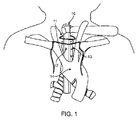
いくつかの実施形態によると、開創器デバイスは、特に、縦隔鏡下アプローチにおいて、心臓の左心房の内側にアクセスし、そこで動作し、例えば、僧帽弁を修復するために有用であり得る。左心房を縦隔鏡下アプローチから暴露するために、6〜8cm切開が、胸骨切痕の上方の前頸部において実施されてもよく、鈍的解離が、気管の前方で行われてもよい。解離平面は、肺静脈および左心房のドームを暴露するために下方に前進されてもよい。これらの構造は、肺動脈の後方にある。縦隔鏡は、ビデオモニタ上での内部構造の可視化のための内視鏡と、頸部切開部から左心房のドームに下方に延在する、手術トンネルを維持するための伸長湾曲後退ブレードとを含有してもよい。 According to some embodiments, the retractor device can be useful, especially in a mediastinoscopic approach, to access and operate on the medial side of the left atrium of the heart, eg, to repair the mitral valve. .. To expose the left atrium from a mediastinal approach, a 6-8 cm incision may be made in the anterior neck above the sternum notch, or a blunt dissection may be made in front of the trachea. .. The dissociation plane may be advanced downward to expose the dome of the pulmonary veins and left atrium. These structures are posterior to the pulmonary artery. The mediastinoscope includes an endoscope for visualization of the internal structure on a video monitor and an elongated curved retraction blade that extends downward from the cervical incision to the dome of the left atrium to maintain the surgical tunnel. May be contained.
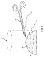
いくつかの実施形態によると、縦隔鏡が、定位置に前進され、心臓を暴露した後、長い針が、作業トンネルを辿って前進され、左心房のドームの中に挿入されてもよい。針の近位ハブから退出する明るい赤色の酸素化血液は、針が、暗い非酸素化血液を搬送する、肺動脈ではなく、左心房に進入したことを示す。ガイドワイヤが、針を通して左心房の中に前進されてもよく、針は、次いで、除去されてもよい。開創器デバイスの内部部材のテーパ状端部は、患者の身体の外側のガイドワイヤ上に装填され、縦隔トンネルを通して前進され、針穿刺部位を通して左心房の中に挿入されてもよい。ガイドワイヤは、次いで、除去されてもよく、エラストマシールは、ガイドワイヤ除去後、止血を維持する。挿入操縦の間、外側管に取り付けられる、2つのワイヤ延在部が、左心房の表面の上方に据え付けられてもよい。横棒の作動に応じて、左心房の内側の内部部材は、2つのワイヤ延在部の1cm上方に後退され、それによって、テントを心房壁内に形成してもよい。テントが張られた心房の垂直の側方に面した壁は、持針器の長軸が手術腔のボアと共線形であるため、縦隔内深くへの巾着縫合糸の設置を促進する。湾曲針の先端は、心房テントの垂直壁と垂直に容易に設置され、持針器の軸方向回転も同様に、巾着糸を設置するために容易に実施される。巾着縫合の完了に応じて、ガイドワイヤが、開創器を通して左心房の中に再挿入され、開創器は、除去され、標準的心血管シースおよび拡張器が、ガイドワイヤに沿って前進され、心臓の中へのアクセスを提供してもよい。縫合糸の遊離端が、ポリマー管類の長さを通して引動され、巾着を心血管シースの周囲で締着し、外科手術用クランプが、その留置縫合糸とともに、ポリマー管の外側上に設置され、一般に、Rumel止血帯として知られるものを形成してもよい。外科手術手技の完了に応じて、ポリマー管は、除去され、縫合糸端部は、縛着され、巾着を恒久的に閉鎖する。 According to some embodiments, the mediastinal mirror may be advanced in place to expose the heart, and then a long needle may be advanced along the working tunnel and inserted into the dome of the left atrium. Bright red oxygenated blood exiting the proximal hub of the needle indicates that the needle has entered the left atrium rather than the pulmonary artery, which carries dark non-oxygenated blood. The guide wire may be advanced into the left atrium through the needle, and the needle may then be removed. The tapered end of the internal member of the retractor device may be loaded onto a guide wire on the outside of the patient's body, advanced through a mediastinal tunnel, and inserted into the left atrium through the needle puncture site. The guide wire may then be removed and the elastomer seal maintains hemostasis after removal of the guide wire. During the insertion maneuver, two wire extensions attached to the lateral canal may be installed above the surface of the left atrium. In response to the actuation of the crossbar, the inner member of the left atrium may be retracted 1 cm above the two wire extensions, thereby forming a tent within the atrial wall. The vertical laterally facing wall of the tented atrium facilitates the placement of purse sutures deep within the mediastinum, as the long axis of the needle holder is co-aligned with the bore of the surgical cavity. The tip of the curved needle is easily installed perpendicular to the vertical wall of the atrial tent, and the axial rotation of the needle holder is also easily performed to install the drawstring thread. Upon completion of the drawstring suture, the guide wire is reinserted into the left atrium through the retractor, the retractor is removed, the standard cardiovascular sheath and dilator are advanced along the guide wire, and the heart Access to the inside may be provided. The free end of the suture is pulled through the length of the polymer tube, tightening the purse around the cardiovascular sheath, and a surgical clamp, along with its indwelling suture, is placed on the outside of the polymer tube. Generally, what is known as a Polymer tourniquet may be formed. Upon completion of the surgical procedure, the polymer tube is removed, the suture end is tied up and the purse is permanently closed.
いくつかの実施形態によると、より大きい切開部が、心房壁内に所望される場合、心血管シース設置の代わりに、電気焼灼エネルギーが、印加され、内部部材は、内部部材の長さの一部または全てに沿って、心房壁の切開を引き起こしてもよい。代替として、解剖刀ブレードが、心臓の内側の補強として作用し、切開の実施に応じて、心内構造への傷害を回避する、心内管状構造とともに、心房壁を切開するために使用されてもよい。直接解剖刀切開は、電気焼灼使用の間に生じる、組織炭化の生成を回避し、これは、一部の外科医によって好まれ得る。開創器デバイスはまた、巾着縫合糸ではなく、一連の結節縫合糸の設置を補助するために使用されてもよい。複数の湾曲針に装備された縫合糸が、心房テントの壁の両方を通して設置され、縫合糸の端部は、外在化される、または頸部切開部を介して、身体から外に出されてもよい。個々の縫合糸は、手技の終了時、縛着され、切開部を閉鎖する。 According to some embodiments, when a larger incision is desired within the atrioventricular wall, electrocautery energy is applied instead of cardiovascular sheath placement and the internal member is one of the lengths of the internal member. Along part or all, an incision in the atrioventricular wall may be triggered. Alternatively, the anatomical sword blade is used to make an incision in the atrial wall, along with an intracardiac tubular structure, which acts as an inner reinforcement of the heart and, depending on the incision, avoids injury to the intracardiac structure. May be good. A direct anatomical sword incision avoids the formation of tissue carbonization that occurs during electrocautery use, which may be preferred by some surgeons. The retractor device may also be used to assist in the placement of a series of nodular sutures rather than a drawstring suture. Sutures mounted on multiple curved needles are placed through both walls of the atrial tent, and the ends of the sutures are externalized or removed from the body through a cervical incision. You may. The individual sutures are tied at the end of the procedure and close the incision.
(参照による組み込み)
本明細書に述べられた全ての刊行物、特許、および特許出願は、各個々の刊行物、特許、または特許出願が、具体的に、個々に、示され、参照することによって組み込まれる場合と同程度に、参照することによって本明細書に組み込まれる。
(Built-in by reference)
All publications, patents, and patent applications described herein are incorporated by reference to each individual publication, patent, or patent application, specifically, individually. To the same extent, it is incorporated herein by reference.
本開示の新規特徴が、添付の請求項に詳細に記載される。本開示の特徴および利点のより深い理解は、本開示の原理が利用される、例証的実施形態を記載する、以下の発明を実施するための形態と、付随の図面とを参照することによって取得されるであろう。 The novel features of the disclosure are described in detail in the appended claims. A deeper understanding of the features and benefits of the present disclosure can be obtained by reference to the embodiments for carrying out the invention below, which describe exemplary embodiments in which the principles of the present disclosure are utilized, and the accompanying drawings. Will be done.
ここで、実装が、詳細に参照されるであろうが、その実施例は、付随の図面に図示される。以下の発明を実施するための形態では、多数の具体的詳細が、種々の説明される実装の完全な理解を提供するために記載される。しかしながら、種々の説明される実装がこれらの具体的詳細を伴わずに実践されてもよいことが、当業者に明白となるであろう。他の事例では、周知の方法、手技、構成要素、回路、およびネットワークは、実装の側面を不必要に曖昧にしないように、詳細に説明されていない。 Here, the implementation will be referenced in detail, but examples thereof are illustrated in the accompanying drawings. In the embodiments for carrying out the invention below, a number of specific details are provided to provide a complete understanding of the various described implementations. However, it will be apparent to those skilled in the art that various described implementations may be practiced without these specific details. In other cases, well-known methods, procedures, components, circuits, and networks are not described in detail so as not to unnecessarily obscure aspects of the implementation.
本開示の多くの修正および変形例が、当業者に明白となるであろうように、その精神および範囲から逸脱することなく行われることができる。本明細書に説明される具体的実装は、一例としてのみもたらされ、本開示は、添付の請求項の観点によってのみ、そのような請求項の権利が与えられた均等物の完全範囲とともに、限定されるべきである。概して、本明細書に説明され、図に図示されるような本開示の側面は、様々な異なる構成において、配列され、代用され、組み合わせられ、分離され、設計されることができ、その全ては、本明細書で明示的に検討されることが、容易に理解されるであろう。 Many modifications and variations of the present disclosure can be made without departing from their spirit and scope, as will be apparent to those skilled in the art. The specific implementations described herein are provided by way of example only, and the present disclosure is made solely in the context of the appended claims, along with the full scope of the equivalents to which such claims are entitled. Should be limited. In general, aspects of the present disclosure, as described herein and illustrated in the drawings, can be arranged, substituted, combined, separated and designed in a variety of different configurations, all of which. , Will be readily understood as expressly discussed herein.
ある実施形態および実施例が、下記に開示されるが、本発明の主題は、具体的に開示される実施形態以外にも、他の代替実施形態および/または使用ならびにその修正および均等物にも拡張する。したがって、本明細書に添付の請求項の範囲は、下記に説明される特定の実施形態のいずれかによって限定されない。例えば、本明細書に開示される任意の方法またはプロセスでは、方法またはプロセスの作用もしくは動作は、任意の好適なシーケンスで実施されてもよく、必ずしも、任意の特定の開示されるシーケンスに限定されない。種々の動作は、ある実施形態を理解する際に有用であり得る様式において、順番に複数の離散動作として説明され得るが、しかしながら、説明の順序は、これらの動作が順序依存であることを含意すると解釈されるべきではない。加えて、本明細書に説明される構造、システム、および/またはデバイスは、統合された構成要素または別個の構成要素として具現化されてもよい。 Although certain embodiments and examples are disclosed below, the subject matter of the present invention is not limited to the specifically disclosed embodiments, but also to other alternative embodiments and / or uses and modifications and equivalents thereof. Expand. Accordingly, the scope of the claims attached herein is not limited by any of the particular embodiments described below. For example, in any method or process disclosed herein, the actions or actions of the method or process may be performed in any suitable sequence and are not necessarily limited to any particular disclosed sequence. .. The various actions can be described in sequence as multiple discrete actions in a manner that may be useful in understanding certain embodiments, however, the order of description implies that these actions are order-dependent. Should not be interpreted as. In addition, the structures, systems, and / or devices described herein may be embodied as integrated or separate components.
種々の実施形態を比較する目的のために、これらの実施形態のある側面および利点が、説明される。必ずしも、全てのそのような側面または利点が、任意の特定の実施形態によって達成されるわけではない。したがって、例えば、種々の実施形態は、本明細書に教示されるような1つの利点または利点群を、必ずしも、本明細書に教示または示唆され得るような他の側面または利点を達成せずに、達成または最適化する様式で行われてもよい。 Certain aspects and advantages of these embodiments are described for the purpose of comparing the various embodiments. Not all such aspects or benefits are achieved by any particular embodiment. Thus, for example, various embodiments do not necessarily achieve one advantage or group of advantages as taught herein, but not necessarily another aspect or advantage as can be taught or suggested herein. , May be done in a manner that achieves or optimizes.
本開示は、その中への1つ以上の縫合糸の設置を補助するための、心臓の心房壁の後退のためのデバイスの展開に関連して説明されるであろう。しかしながら、当業者は、これが、限定することを意図するものではなく、本明細書に開示されるデバイスおよび方法が、他の中空器官または生物学的構造にアクセスするために、他の解剖学的面積において、および他の外科手術手技において使用されてもよいことを理解するであろう。解剖学的面積は、例えば、胸腔、腹腔、頸部、背中または脊椎、もしくは当業者に公知の任意の他の解剖学的面積を含んでもよい。中空器官または生物学的構造は、例えば、心臓、胃、結腸、小腸、膀胱、胆嚢、胆管、卵管、尿管、虫垂、または当業者に公知の任意の他の中空器官を含んでもよい。手技は、例えば、僧帽弁置換または修復、僧帽弁形成術、腱索修復または置換、冠動脈バイパス移植、結腸直腸外科手術、小腸外科手術、肥満外科手術、胃外科手術、もしくは中空器官の中へのアクセスのための切開部を要求し得、切開部の周囲における縫合糸の設置のために組織を後退させるための低侵襲性デバイスおよび方法から利点を享受するであろう、他の外科手術手技を含んでもよい。 The present disclosure will be described in connection with the deployment of a device for retraction of the atrial wall of the heart to assist in the placement of one or more sutures therein. However, one of ordinary skill in the art is not intended to limit this, and other anatomical devices and methods disclosed herein allow access to other hollow organs or biological structures. It will be appreciated that it may be used in area and in other surgical procedures. The anatomical area may include, for example, the thoracic cavity, abdominal cavity, neck, back or spine, or any other anatomical area known to those of skill in the art. The hollow organ or biological structure may include, for example, the heart, stomach, colon, small intestine, bladder, gallbladder, bile duct, oviduct, ureter, appendix, or any other hollow organ known to those of skill in the art. Procedures include, for example, mitral valve replacement or repair, mitral valvuloplasty, suture repair or replacement, coronary bypass transplantation, colorectal surgery, small bowel surgery, obesity surgery, gastric surgery, or in hollow organs. Other surgeries that may require an incision for access to and will benefit from minimally invasive devices and methods for retracting tissue due to the placement of sutures around the incision. The procedure may be included.
非限定的実施例として、ここで、左心房壁の再構成を実施し、進入用切開部位から遠隔の緊密空間内における巾着縫合糸の設置を促進するための、内視鏡下組織開創デバイスの使用を参照する。例えば、入口切開部は、胸骨上切痕内等の患者の頸部内にあってもよく、これは、身体の縦隔空間を通した経路を介して、左心房壁へのアクセスを可能にし得る。そのような経路は、縦隔鏡または他の胸骨上窩アクセスデバイスによって進行されるものに実質的に類似し得、多くの場合、骨(胸骨、胸骨柄、または肋骨等)および/または横隔膜を切断する、もしくは肋骨を広げることを要求する、開心外科手術法と比較して、患者への最小限の傷害を伴って、心臓の上部への直接アクセスを提供し、それによって、そのような傷害と関連付けられた合併症を回避し得る。本明細書では、左心房の天蓋部を含む、標的組織へのアクセスを具体的に参照する。内視鏡下組織開創デバイスが、本明細書に説明されるように、患者の肋骨および/または胸骨傷害もしくは改変せずに、胸骨上窩アクセス部位における穿通部を介して、左心房の天蓋部を通して前進され得る。内視鏡下組織開創デバイスは、心臓の心膜を穿通または切断せずに、左心房の天蓋部を通して前進され得る。 As a non-limiting example, here, an endoscopic tissue resection device for performing a reconstruction of the left atrial wall and facilitating the placement of a drawstring suture in a close space distant from the incision site for entry. See usage. For example, the entrance incision may be within the patient's neck, such as within the suprasternal notch, which allows access to the left atrial wall via a route through the mediastinal space of the body. obtain. Such pathways can be substantially similar to those carried out by a mediastinoscope or other suprasternal notch access device, often through the bone (such as the sternum, sternum, or ribs) and / or the diaphragm. It provides direct access to the upper part of the heart with minimal injury to the patient compared to open heart surgery, which requires cutting or widening the ribs, thereby with such injury. The associated complications can be avoided. This specification specifically refers to access to target tissue, including the canopy of the left atrium. The endoscopic tissue wound device, as described herein, through the perforation at the suprasternal notch access site, without injury or modification of the patient's ribs and / or sternum, canopy of the left atrium. Can be advanced through. The endoscopic tissue wound device can be advanced through the canopy of the left atrium without penetrating or cutting the pericardium of the heart.
図1は、頸部切開部11を通して設置され、心臓の左心房の上方に位置付けられる、従来の縦隔鏡10の構成を図示する。頸部切開部11は、胸骨切痕12の上方またはそれに隣接してあり得る。胸骨上切痕12は、組織に下層骨がない、患者の鎖骨間の間隙の略三角形である。切開場所11は、胸骨上切痕12の三角形間隙内、その上方、またはそれを通してあってもよい。縦隔鏡10は、胸骨上切痕12内の切開部11を通して挿入され、気管13の前方かつ大動脈弓14の後方の解剖学的平面において、気管13に沿って、身体の縦隔空間を通して、心臓の左心房に向かって、患者の身体の中に前進され得る。
FIG. 1 illustrates the configuration of a conventional
図2Aは、配向のために描写される、左下肺静脈16を伴う心臓15の後面図を示す。肺静脈によって境界される面積の中心にあって、心膜を含まない、左心房15の天蓋部が、例えば、第PCT/US2018/042171号(その全内容は、参照することによって本明細書に組み込まれる)に説明されるように、縦隔鏡または胸骨上窩アクセスデバイスを使用した外科手術手技のための左心房15の中への標的進入点であってもよい。図2Bは、左心房心臓15への縦隔鏡下または胸骨上窩アプローチによって提供される、作業面積17の円筒形形状の境界を示す。外科手術用器具を胸骨上切痕を介して患者の中に導入することによって、左心房15の天蓋部は、本明細書に説明されるように、骨を切断せずに、または患者の他の内部構造への傷害を引き起こさずに、アクセスされ得る。しかしながら、開心アクセスと比較して、胸骨上窩アプローチを用いて利用可能となる、利用可能作業空間17は、その中で作業するためのより限定された器具運動範囲を提供し得る。本開放アクセス面積17は、途絶することが有害となるであろう、解剖学的構造によって囲繞され得、したがって、外科手術用器具アクセスは、円筒形17の上部によって画定された面積に限定され得る。
FIG. 2A shows a rear view of the
図3A−3Cは、従来の技法を使用して左心房15内に巾着縫合糸20パターンを設置するステップを示す。湾曲針19に取り付けられた縫合糸18が、巾着縫合糸20を組織壁内に設置するために使用されてもよい。適切な縫合技法は、図3Aに示されるように、湾曲針19の遠位先端が、左心房15の壁を通して垂直に、標的組織、すなわち、左心房15の中に挿入されることを要求する。次に、湾曲針19は、図3Bに示されるように、標的組織のある区分を組み込むように回転される。組織の複数の咬刺が、図3Cに示されるように、略円形パターンにおいて実施され、巾着縫合糸20を形成する。外科手術用持針器(図4に示される持針器21等)が、湾曲針19を握持および操作し、巾着縫合糸20を形成するために使用されてもよい。
FIG. 3A-3C shows the steps of placing a
図4は、左心房15内への巾着縫合糸の設置の間、湾曲針19を握持する外科手術用持針器21を示す。外科手術用持針器21は、縫合糸設置の間、湾曲針19の中心部分を握持し、湾曲針19を操作するように示される。外科手術用持針器21は、典型的には、縫合糸を設置するとき、湾曲針19の中心部分に直交して配向される。図3Aに示されるように、左心房15の表面と垂直に湾曲針19を挿入し、図3Bに示されるように、湾曲針19を回転させ、巾着縫合の実行の間、縫目を設置するために、外科手術用持針器21は、したがって、従来の技法を使用すると、組織表面と比較的に平行に配向される。
FIG. 4 shows the
図5は、従来の技法を使用した巾着縫合20の実行の間、持針器21の要求される配向が、縦隔鏡下または胸骨上窩アプローチ経路を介して左心房15の天蓋部にアクセスするときに存在する、作業トンネル17の境界の外側にあることを示す。図4に示されるように、左心房15内に巾着縫合糸20を設置するために使用される、持針器21の典型的開胸外科手術の位置付けは、持針器21のハンドルをそのようなアプローチのために利用可能な作業空間17のはるか外側に設置させる。したがって、利用可能な作業空間17が、より侵襲性アクセス経路で利用可能となるであろう持針器21の完全運動範囲を提供しないとき、巾着縫合糸20設置を促進するためのデバイス、システム、および方法の必要性がある。
FIG. 5 shows that during the performance of the
図6A−6Dは、内視鏡下巾着縫合糸付き開創器22の種々の図を示す。図6Aは、内視鏡下開創デバイス22の正面図を示す。図6Bは、内視鏡下開創デバイスの側面図を示す。図6Cは、内視鏡下開創デバイス22の後面図を示す。図6Dは、内視鏡下開創デバイス22のテーパ状遠位端26を示す。
6A-6D show various views of the
内視鏡下組織開創デバイス22は、第1のシャフト25と、そこに摺動可能に結合される、第2のシャフト23とを備えてもよい。第2のシャフト23は、第1のシャフト25に対して縦方向に移動可能であってもよい。故に、第1のシャフト25は、第2のシャフト23に対して縦方向に移動可能であってもよい。いくつかの実施形態では、第1のシャフト25の少なくとも一部は、その中で縦方向に平行移動するように、示されるように、第2のシャフト23の管腔内に摺動可能に配置されてもよい。代替として、または組み合わせて、第1のシャフト25の少なくとも一部は、第2のシャフト23に隣接して、例えば、横並び様式において、摺動可能に結合されてもよい。内部部材26が、第1のシャフト25の縦軸に対して横方向または垂直方向にそこから延在するように、第1のシャフト25に結合されてもよい(図6Bにおいてハイライトされるように)。一対の外部部材24がそれぞれ、内部部材26の横方向と比較的に平行にそこから延在するように、第2のシャフト23に結合されてもよい(図6Bにおいてハイライトされるように)。対の外部部材24は、相互から離間されてもよく、第1および第2のシャフトの縦軸に対して横方向に配置される平面にあってもよい。示されない代替実施形態では、第2のシャフト23の代わりに、2つの別個のシャフトが、提供されてもよく、各外部部材24は、個々のシャフトに結合されてもよく、これは、第1のシャフトに対して移動可能である。さらに、2つを上回る外部部材24が、提供されてもよく、全て、1つのシャフトに結合される、またはそれぞれ、別個のシャフトに結合される。
The endoscopic tissue wound
内部部材26は、本明細書に説明されるように、標的組織内の穿通部を通して、中空器官(例えば、心臓)の内部の中に前進されるように構成されてもよい。内部部材26は、それを通して前進された後、標的組織の遠位表面に非外傷的に係合するように構成される、近位に面した表面を備えてもよい。対の外部部材24は、内部部材26がその中に前進されるとき、中空器官の外側に留まり得る。対の外部部材24はそれぞれ、標的組織の近位表面に非外傷的に係合するように構成される、遠位に面した表面を有してもよい。
The
内部部材26は、テーパ状遠位端26Eを備えてもよい。遠位端26Eは、本明細書に説明されるように、標的組織を通した内部部材26の前進を促進するようにテーパ状または鋭的にされてもよい。内部部材26のテーパ状遠位端26Eは、本明細書に説明されるように、ガイドワイヤに沿って前進され、針穿刺部位の中により容易に挿入され、内部部材26が心臓の外壁を通して左心房の中に挿入されるにつれて、止血シールを維持しながら、穿刺部位を拡張させることを可能にし得る。内部部材26の全部または遠位部分は、下記にさらに説明されるように、随意に、伝導性であって、電気焼灼エネルギーを送達し、標的組織の穿通を促進するように構成されてもよい。
The
内部部材26は、内部部材26が、標的組織の遠位表面に係合し、血液、体液、または中空器官の他の内部内容物の漏出を阻止する間、標的組織に接触するように構成される、拡開部または拡開部分27を備えてもよい。拡開部27は、内部部材26の近位領域、すなわち、内部部材26の第1のシャフト25への取付点またはその近傍内に位置してもよい。内部部材26が、例えば、心臓が鼓動している間、心臓壁の中に挿入されると、拡開部は、出血が心臓壁の後退の間に生じないように、心臓組織内の穿刺部位をシールし得る。
The
いくつかの実施形態では、内部部材26は、図6Dに示されるように、管腔29を備えてもよい。管腔29は、それを通してガイドワイヤを摺動可能に受容するように構成されてもよい(例えば、図14D−14Eに示されるように)。エラストマシール28が、図6C−6Dに示されるように、ガイドワイヤ管腔29とともに配置されてもよい。エラストマシール28は、例えば、管腔29の近位端に位置付けられてもよい。エラストマシール28は、内部部材26が、その中に配置されると、標的組織をシールし、管腔29を通した流体(例えば、血液または他の体液)流動を防止するように構成されてもよい。エラストマシール28は、ガイドワイヤが、内部部材26の内側に存在するとき、およびガイドワイヤの除去後、管腔29が空であるとき、中空器官からの流体損失を防止するように構成されてもよい。
In some embodiments, the
内部部材26は、本明細書に説明されるように、外部部材26間に縦方向に延在する平面に沿って、遠位位置と近位位置との間で、対の外部部材24に対して縦方向に移動可能であってもよい。遠位位置から、対の外部部材24を越えて、近位位置まで後退されると(例えば、図11A−11Bに示されるように)、内部部材26は、牽引力を標的組織に印加し得る。対の外部部材24は、逆牽引力を内部部材26の対向する側方側の標的組織に印加し得る。標的組織に印加される牽引力および逆牽引力は、それぞれ、内部部材26と外部部材24のうちの1つとの間に延在する、それぞれ、側方に面した表面を有する、2つの略垂直部分に、内部部材26の周囲で折畳されるように、標的組織を再成形し得る(例えば、図12B−12Cに示されるように)。側方に面した表面は、本明細書に説明されるように、限られた狭い解剖学的状況において、中空器官への器具アクセスおよびその中での切開部閉鎖のために、縫合糸設置、例えば、巾着縫合糸設置を可能にし得る。
The
第1のシャフト25は、本明細書に説明されるように、第2のシャフト23に対して平行移動するように構成されてもよい。第2のシャフト23に対する第1のシャフト25の平行移動は、内部部材26を遠位位置から近位位置に作動させ得る。シャフト23、25は、平行、同心、または他の好適な配列に配列されてもよい。
The
いくつかの実施形態では、第1のシャフト25は、第2のシャフト23の少なくとも一部内に摺動可能に配置されてもよい。第2のシャフト23は、第2のシャフト23の近位端の対向壁内に配置される、少なくとも2つのスロット23Sを備えてもよい。第1のシャフト25は、スロット23Sを通して延在するように構成される、横棒30を備えてもよい。横棒30は、第2のシャフト23に対する第1のシャフト25の平行移動のための制御アクチュエータとして作用してもよい。スロット23S内の横棒30の平行移動は、本明細書に説明されるように、第1のシャフト25を第2のシャフト23に対して平行移動させ得る。代替として、または組み合わせて、横棒30は、第1のシャフト25と第2のシャフト23を楔止し、2つの間の相対的回転を防止する、役割を果たし得る。横棒30およびスロット23Sは、例示的であって、限定することを意味するものではないことが、当業者によって理解されるであろう。横棒30は、限定ではないが、レールとガイドの組み合わせ、摩擦ホイール、電気または磁気モータ、電気的に収縮するニチノール(R)ワイヤ、および同等物を含む、第2のシャフト23に対する第1のシャフト25の縦方向平行移動を制御するための当技術分野において公知の任意の他のタイプによって代用されてもよい。
In some embodiments, the
第1のシャフト25は、手技の間、血液または他の体液を標的組織および外科術野から除去するように構成される、吸入管腔または開放チャネル31を備えてもよい。吸入管腔は、第1のシャフト25の遠位端から横棒30の片側まで延在してもよい。吸入管腔31は、例えば、横棒30に取り付けられる、真空ライン32を介して、負圧源に流動的に結合されてもよい。
The
内部部材26は、本明細書に説明されるように、電気焼灼エネルギーを標的組織に印加し、穿通部または切開部をその中に生成するように構成されてもよい。内部部材26は、内部部材26の長さの少なくとも一部に沿って、切開部を標的組織内に生成するように構成されてもよい。内部部材26は、例えば、電極を備えてもよい。代替として、または組み合わせて、内部部材26は、電極33Eを備えてもよい、またはそれに伝導性に結合されてもよい。電極33Eは、内部部材26の全部または一部を構成してもよい、もしくは内部部材26に取り付けられる、別個の電極要素を構成してもよい。いくつかの実施形態では、内部部材26の一部は、電気的に絶縁材料で被覆され、選択された部分を暴露されたままにし、エネルギーを組織に送達してもよい。ワイヤ33が、横棒30から第1のシャフト25を辿って延在し、内部部材26に接続し、電気焼灼エネルギーが内部部材26の一部に印加され、切開部を標的組織の壁内に生成することを可能にしてもよい。第1のシャフト25の外側表面は、非伝導性材料でコーティングされ、切開線の外側の組織への非意図的エネルギー伝導を回避してもよい。
The
内部部材26は、その遠位端において、第1のシャフト25に結合されてもよい。いくつかの実施形態では、内部部材26は、第1のシャフト25の遠位端を備えてもよい。いくつかの実施形態では、内部部材26は、中空管または中空シャフトを備えてもよい。
The
対の外部部材24は、その遠位端において、第2のシャフト23に結合されてもよい。いくつかの実施形態では、対外部部材24は、第2のシャフト23の遠位端を構成してもよい。いくつかの実施形態では、対の外部部材24は、少なくとも2つのワイヤ延在部を備えてもよい。
The pair of
いくつかの事例では、第1のシャフト25の少なくとも一部は、剛性であってもよい。例えば、第1のシャフト25の全長が、剛性であってもよい。代替として、第1のシャフト25の遠位部分および/または近位部分ならびに/もしくはその間の任意の部分は、剛性であってもよい。第1のシャフト25は、例えば、剛性管または剛性中実シャフトを備えてもよい。
In some cases, at least a portion of the
第1のシャフト25は、ポリカーボネート等の高硬度ポリマー、液晶プラスチック、ナイロン、PTFE、ABS、ポリプロピレン、または同等物を含む、材料から構築されてもよい。代替として、または組み合わせて、第1のシャフト25は、ステンレス鋼、チタン、または同等物等の金属を含む、材料から構築されてもよい。
The
いくつかの事例では、第2のシャフト23の少なくとも一部は、剛性であってもよい。例えば、第2のシャフト23の全長が、剛性であってもよい。代替として、第2のシャフト23の遠位部分および/または近位部分ならびに/もしくはその間の任意の部分は、剛性であってもよい。第2のシャフト23は、例えば、剛性管、剛性中空シャフトを備えてもよい。いくつかの実施形態では、例えば、第1のシャフト25および第2のシャフト23の少なくとも一部が、(同軸の代わりに)相互に隣接して配置されるとき、第2のシャフト23は、剛性中実シャフトを備えてもよい。
In some cases, at least a portion of the
第2のシャフト23は、ポリカーボネート等の高硬度ポリマー、液晶プラスチック、ナイロン、PTFE、ABS、ポリプロピレン、または同等物を含む、材料から構築されてもよい。代替として、または組み合わせて、第2のシャフト23は、ステンレス鋼、チタン、または同等物等の金属を含む、材料から構築されてもよい。
The
第2のシャフト23は、患者の身体内の開口部を通して設置された、外科手術用器具、内視鏡、縦隔鏡、または胸骨上窩アクセスデバイス、または同等物の作業チャネルの中に挿入されるように構成されてもよい。例えば、第2のシャフト23は、心臓の左心房の天蓋部にアクセスするために、患者の胸骨上切痕に隣接する開口部を通して設置された、縦隔鏡または胸骨上窩アクセスデバイスの作業チャネルの中に挿入されるように構成されてもよい。
The
いくつかの事例では、内部部材26の少なくとも一部は、剛性であってもよい。例えば、内部部材26の全長が、剛性であってもよい。代替として、内部部材26の遠位部分および/または近位部分ならびに/もしくはその間の任意の部分は、剛性であってもよい。内部部材26は、例えば、剛性管または剛性固体シャフトを備えてもよい。内部部材26は、剛性中空管または剛性中空シャフトを備えてもよい。
In some cases, at least a portion of the
内部部材26は、ポリカーボネート等の高硬度ポリマー、液晶プラスチック、ナイロン、PTFE、ABS、ポリプロピレン、または同等物を含む、材料から構築されてもよい。代替として、または組み合わせて、内部部材26は、ステンレス鋼、チタン、または同等物等の金属を含む、材料から構築されてもよい。
The
いくつかの事例では、対の外部部材24の一方または両方の少なくとも一部は、剛性であってもよい。例えば、対の外部部材24の一方または両方の全長が、剛性であってもよい。代替として、対の外部部材24の一方または両方の遠位部分および/または近位部分ならびに/もしくはその間の任意の部分は、剛性であってもよい。対の外部部材24の一方または両方は、例えば、剛性ワイヤ延在部を備えてもよい。
In some cases, at least one or both of the pair of
対の外部部材24の一方または両方は、ポリカーボネート等の高硬度ポリマー、液晶プラスチック、ナイロン、PTFE、ABS、ポリプロピレン、または同等物を含む、材料から構築されてもよい。代替として、または組み合わせて、対の外部部材24の一方または両方は、ステンレスばね鋼鉄、チタン、または同等物等の金属を含む、材料から構築されてもよい。
One or both of the pair of
図7A−7Bは、内部部材26と、一対の外部部材24とを備える、内視鏡下開創デバイス22を示す。開創デバイス22は、図6A−6Dに示される開創デバイスに実質的に類似し得るが、内部部材26および/または対の外部部材24の一方または両方のうちの1つ以上のものは、縦方向構成から横方向構成に移動可能であるように構成されてもよい。図7Aは、縦方向構成における内部部材26および外部部材24を伴う、内視鏡下開創器22を示す。図7Bは、横方向構成における内部部材26および外部部材24を伴う、内視鏡下開創器22を示す。内部部材26および/または外部部材24は、標的組織に隣接する横方向構成に移動される前に、縦方向構成において、標的組織へのアクセス経路の作業空間を通して前進されてもよい。例えば、内部部材26および/または外部部材24は、本明細書に説明されるように、内部部材26が中空器官の中に標的組織を通して前進される前または後に、横方向構成に移動されてもよい。内部部材26は、本明細書に説明されるように、横方向構成にあるとき、標的組織の遠位表面に係合するように構成されてもよい。外部部材24は、本明細書に説明されるように、横方向構成にあるとき、標的組織の近位表面に係合するように構成されてもよい。内部部材26および/または外部部材24の縦方向構成は、開創デバイス22により小さい外形を提供し得、これは、本明細書に説明されるように、縦隔鏡または胸骨上窩アクセスデバイスによって提供されるもの等の作業空間を通した開創デバイス22の前進および除去を促進し得る。
FIG. 7A-7B shows an endoscopic
いくつかの実施形態では、内部部材26および/または外部部材24は、縦方向構成から横方向構成に回転可能に移動可能であってもよく、その逆も同様である。内部部材26は、例えば、第1のシャフト25へのその取付点に、枢動継手50を備えてもよい。代替として、または組み合わせて、外部部材24の一方または両方はそれぞれ、第2のシャフト23のその取付点に、枢動継手52を備えてもよい。内部部材26および/または外部部材24は、それぞれ、部材26、24をその縦方向構成と横方向構成との間で移動させるために、枢動継手50、52の周囲で回転されてもよい。いくつかの実施形態では、内部部材26および/または外部部材24は、縦方向構成にあるとき、それぞれ、内部部材26および/または外部部材24に印加される力に応答して、縦方向構成から横方向構成に回転されるように構成されてもよい。いくつかの実施形態では、内部部材26および/または外部部材24は、縦方向構成における、それぞれ、内部部材26および/または外部部材24に印加される力の除去に応答して、縦方向構成から横方向構成に回転されるように構成されてもよい。いくつかの実施形態では、内部部材26および/または外部部材24は、印加される力の不在下、縦方向構成または横方向構成に向かって付勢されてもよい。
In some embodiments, the
内部部材26の縦方向構成は、第1のシャフト25の縦軸と略平行であってもよい。内部部材26の縦方向構成は、例えば、第1のシャフト25の縦軸の約30°、25°、20°、15°、10°、または約5°以内であってもよい。内部部材26の横方向構成は、第1のシャフト25の縦軸と略垂直であってもよい。内部部材26の横方向構成は、例えば、第1のシャフト25の横軸の約30°、25°、20°、15°、10°、または約5°以内であってもよい。
The vertical configuration of the
外部部材24の縦方向構成は、第2のシャフト23の縦軸と略平行であってもよい。外部部材24の縦方向構成は、例えば、第2のシャフト23の縦軸の約30°、25°、20°、15°、10°、または約5°以内であってもよい。外部部材24の横方向構成は、第2のシャフト23の縦軸と略垂直であってもよい。外部部材24の横方向構成は、例えば、第2のシャフト23の横軸の約30°、25°、20°、15°、10°、または約5°以内であってもよい。
The vertical configuration of the
いくつかの実施形態では、内部部材26および/または対の外部部材24の一方または両方は、1つ以上の係止機構(例えば、図8A−10Bに示される係止機構のうちの1つ以上のもの)に結合され、部材26、24を縦方向構成および/または横方向構成に維持してもよい。いくつかの実施形態では、対の外部部材24はそれぞれ、少なくとも1つの係止機構に結合されてもよい。いくつかの実施形態では、係止機構を係脱することは、内部部材26および/または対の外部部材24の一方または両方を縦方向構成から横方向構成に作動させ得る。いくつかの実施形態では、係止機構を係脱することは、内部部材26および/または対の外部部材24の一方または両方を横方向構成から縦方向構成に作動させ得る。いくつかの実施形態では、内部部材26および/または対の外部部材24の一方または両方のうちの1つ以上のものは、複数の係止機構、例えば、部材を縦方向構成に維持するように構成される、第1の係止機構と、部材を横方向構成に維持するための、係止機構構成とを備えてもよい。
In some embodiments, one or both of the
図8A−8Bは、内視鏡下開創デバイスの内部部材26および/または外部部材(図示せず)を縦方向構成と横方向構成との間で移動させるための機構を示す。内視鏡下開創デバイスは、図7A−7Bに示される開創デバイスに実質的に類似し得るが、内部部材26および/または対の外部部材の一方または両方は、内部部材26に結合される枢動継手50(および/または外部部材に結合されるときの図7A−7Bに示される継手52)内に1つ以上の戻り止め58を備える、1つ以上の係止機構に動作可能に結合され得る。戻り止め58は、内部部材26および/または対の外部部材の一方または両方を、それぞれ、第1のシャフト25または第2のシャフトに対して縦方向構成または横方向構成のいずれかに拘束し得る。本明細書に説明されるように、縦方向位置において作業空間を通して前進された後、内部部材26および/または対の外部部材の一方または両方は、力を、それぞれ、内部部材26および/または対の外部部材の一方または両方に印加することによって、横方向構成におよび/またはから枢動されてもよい。例えば、側方荷重が、作業空間内の別の器具(開創器等)を用いて、または適切に剛性かつ堅牢な解剖学的構造(椎体等)によって、内部部材26および/または対の外部部材の一方または両方の遠位端に対してかけられもよい。
8A-8B show a mechanism for moving the
いくつかの実施形態では、内部部材26および/または外部部材は、それぞれ、縦方向構成における内部部材26および/または外部部材に印加される力に応答して、縦方向構成から横方向構成に回転されるように構成されてもよい。いくつかの実施形態では、内部部材26および/または外部部材は、それぞれ、横方向構成における内部部材26および/または外部部材に印加される力に応答して、横方向構成から縦方向構成に回転されるように構成されてもよい。内部部材26および/または外部部材を縦方向位置に維持する必要がある戻り止め58の保持力の量は、縦方向位置が、作業空間を通した開創デバイスの前進のためにのみ使用され得、付加的荷重が殆どまたは全く、挿入および前進の間、枢動部50上にかけられ得ないため、横方向位置を維持するために必要とされる保持力を有意に下回り得る。横方向位置を維持するために必要とされる戻り止め58の保持力は、本明細書に説明されるように、標的組織を操作しながら横方向位置を維持するために十分な力であり得る。例えば、縦方向構成にあるとき、戻り止め58は、約0.10〜約1ポンドの範囲内の力が、それぞれ、内部部材26および/または外部部材に印加されるとき、内部部材26および/または外部部材から係脱するように構成されてもよい。代替として、または組み合わせて、横方向構成にあるとき、戻り止め58は、約2〜約5ポンドの範囲内の力が、それぞれ、内部部材26および/または外部部材に印加されるとき、内部部材26および/または外部部材から係脱するように構成されてもよい。
In some embodiments, the
図9A−9Bは、内視鏡下開創デバイスの内部部材26および/または外部部材(図示せず)を縦方向構成と横方向構成との間で移動させるための別の機構を示す。内視鏡下開創デバイスは、図7A−7Bに示される開創デバイスに実質的に類似し得るが、内部部材26および/または対の外部部材の一方または両方は、1つ以上の戻り止め58および1つ以上のワイヤアクチュエータ56を備え、部材26、24を縦方向構成および/または横方向構成に維持する、1つ以上の係止機構に動作可能に結合され得る。戻り止め58は、図8A−8Bに説明されるものに実質的に類似し得る。ワイヤアクチュエータ56は、第1のシャフト25(または外部部材に結合されるときの第2のシャフト)内に摺動可能に配置され、戻り止め58に機能的に結合されてもよい。ワイヤアクチュエータ56は、戻り止め58に対応するように成形されてもよい。戻り止め58およびワイヤアクチュエータ56は、内部部材26および/または対の外部部材の一方または両方を、それぞれ、第1のシャフト25または第2のシャフトに対して縦方向構成または横方向構成のいずれかに拘束し得る。本明細書に説明されるように、縦方向位置において作業空間を通して前進された後、内部部材26および/または対の外部部材の一方または両方は、ワイヤアクチュエータ56を、それぞれ、第1のシャフト25または第2のシャフト内で摺動させることによって、横方向構成におよび/またはから枢動され得る。例えば、図9Aに示される中空矢印の方向にワイヤアクチュエータ56を引動させることは、本明細書に説明されるように、戻り止め58を係脱し、縦方向構成から横方向構成への内部部材26および/または対の外部部材の一方または両方の移動を可能にし得る。係止機構を係脱後、ワイヤアクチュエータ56機構が戻り止め58と係合される場合に必要とされたであろう側方荷重と比較して、はるかに低いレベルの側方荷重が、内部部材26および/または対の外部部材の一方または両方を縦方向構成から横方向構成に移動させるために要求され得る。いくつかの実施形態では、内部部材26および/または対の外部部材の一方または両方は、本明細書に説明されるように、所望の構成に向かって付勢されてもよい。例えば、いったん係止機構が係脱されると、内部部材26および/または対の外部部材の一方または両方を横方向構成に付勢し得る、ばね要素が、含まれてもよい。ワイヤアクチュエータ56を図9Bに示される中実矢印の方向に引動または押動させることは、組織後退の間、戻り止め58に再係合し、内部部材26および/または対の外部部材の一方または両方を所望の構成、例えば、横方向構成に係止し得る。
9A-9B show another mechanism for moving the
図10A−10Bは、内視鏡下開創デバイス22の内部部材26および/または外部部材24を縦方向構成と横方向構成との間で移動させるためのさらに別の機構を示す。内視鏡下開創デバイス22は、図7A−7Bに示される開創デバイスに実質的に類似し得るが、内部部材26および/または対の外部部材の一方または両方は、1つ以上の戻り止め58および1つ以上の剛性要素60、62を備え、それぞれ、部材24、26を縦方向構成および/または横方向構成に維持する、1つ以上の係止機構に動作可能に結合され得る。戻り止め58は、図8A−8Bに説明されるものに実質的に類似し得る。剛性要素62、60が、それぞれ、内部部材26および/または対の外部部材24の一方または両方に動作可能に結合されてもよい。剛性要素62、60は、それぞれ、枢動部50、52から短距離を空けて、内部部材26および/または対の外部部材24の一方または両方に結合されてもよい。剛性要素60、62は、それぞれ、第2のシャフト23または第1のシャフト25内に摺動可能に配置されてもよい。剛性要素62、60は、圧縮されると、力を内部部材26および/または対の外部部材24の一方または両方に印加し、内部部材26および/または対の外部部材24の一方または両方を、それぞれ、縦方向構成に維持するように構成されてもよい。剛性要素62、60への張力付与は、枢動部50、52から少なくとも第1の距離だけ離れるように剛性要素62、60を移動させ、内部部材26および/または対の外部部材24の一方または両方に印加される力を除去し、内部部材26および/または対の外部部材24の一方または両方を縦方向構成から横方向構成に移動させ得る。第1の距離は、短距離、例えば、約1mm〜約20mmの範囲内の距離であってもよい。剛性要素62、60が張力を付与される距離が長いほど、回転を引き起こすために必要とされる力が少なくなることが、当業者によって理解されるであろう。
10A-10B show yet another mechanism for moving the
本明細書に説明される係止機構のいずれかは、任意の所望の組み合わせにおいて組み合わせられ、縦方向位置から横方向位置へのおよびその逆の内部部材26および/または外部部材24の回転を提供してもよいことが、当業者によって理解されるであろう。例えば、いくつかの実施形態では、内部部材26および/または外部部材24は、1つ以上の戻り止め58と、1つ以上の剛性要素60、62とを備えてもよい。いくつかの実施形態では、内部部材26および/または外部部材24は、1つ以上の戻り止め58と、1つ以上のワイヤアクチュエータ56と、1つ以上の剛性要素60、62とを備えてもよい。いくつかの実施形態では、内部部材26および/または外部部材24はそれぞれ、同一係止機構を備えてもよい。いくつかの実施形態では、内部部材26および/または外部部材24のうちの1つ以上のものは、異なる係止機構を備えてもよい。
Any of the locking mechanisms described herein can be combined in any desired combination to provide rotation of the
図11Aは、一対の離間された外部部材24の下方(遠位)に遠位構成における内部部材26を備える遠位部分を有する、内視鏡下巾着縫合糸付き開創器22を示す。開創デバイス22は、本明細書に説明される開創デバイスのいずれかに実質的に類似し得る。図11Bは、2つの外部部材24の上方(近位)に近位構成における内部部材26を伴う、内視鏡下巾着縫合糸付き開創器22を示す。内部部材26は、対の外部部材24に対して遠位位置と近位位置との間で縦方向に移動可能であってもよい。内部部材26は、対の外部部材24間に延在する運動平面に沿って、縦方向に移動可能であってもよい。本運動平面は、外部部材24のそれぞれを含有する、横方向平面と略垂直であってもよい。スロット23S内の横棒30の平行移動は、第1のシャフト25を第2のシャフト23に対して平行移動させ得、これは、内部部材26を外部部材24に対して遠位位置(スロット23Sの遠位端に対応し得る)と近位位置(スロット23Sの近位端に対応し得る)との間で縦方向に移動させ得る。図11Aに示される遠位位置から、対の外部部材24を越えて、図11Bに示される近位位置に後退されると、内部部材26は、本明細書に説明されるように、牽引力を標的組織に印加し得る。対の外部部材24は、本明細書に説明されるように、逆牽引力を内部部材26の対向する側方側の標的組織に印加し、組織を再成形し得る。
FIG. 11A shows an endoscopic drawstring sutured
内部部材26は、遠位位置にあるとき、対の外部部材24の約0.5〜3cm、好ましくは、1〜2cm遠位に位置付けられるように構成されてもよい。
The
内部部材26は、近位位置にあるとき、対の外部部材24の約0.5−3cm、好ましくは、1−2cm近位に位置付けられるように構成されてもよい。
The
図12A−12Cは、内視鏡下巾着縫合糸付き開創器22を使用した標的組織、例えば、心房壁の後退の機構を示す。図12Aは、一対の離間された外部部材24の下方に遠位構成における内部部材26を備える遠位部分を有する、開創デバイス22を示す。開創デバイス22は、本明細書に説明される開創デバイスのいずれかに実質的に類似し得る。内部部材26は、左心房15の壁内の穿刺部34を通して前進され、心房壁の遠位内部表面に係合されるように示される。図12Bは、2つの外部部材24の上方の近位構成における内部部材26を伴う、開創器22を示す。内部部材26は、本明細書に説明されるように、対の外部部材24間に延在する平面に沿って、対の外部部材24に対して縦方向に移動可能であってもよい。いくつかの実施形態では、横棒30の平行移動は、本明細書に説明されるように、内部部材26を外部部材24に対して遠位位置と近位位置との間で縦方向に移動させてもよい。2つの外部部材24は、内部部材26が近位位置にあるとき、心房壁の近位外側表面に係合するように構成されてもよい。牽引力が、図12Aに示される遠位位置から、対の外部部材24を越えて、図12Bに示される近位位置に後退されるにつれて、内部部材26によって、左心房壁に印加されてもよい。対の外部部材24は、本明細書に説明されるように、逆牽引力を内部部材26の対向する側方側の標的組織に印加し得る。標的組織に印加される牽引力および逆牽引力は、図12Cに示されるように、それぞれ、内部部材26と外部部材24のうちの1つとの間に延在する側方に面した表面35を有する一対の略垂直部分Vに、内部部材26にわたって折畳されるように、標的組織を再成形し得る。テントが張られた心房壁の側方に面した表面35は、本明細書に説明されるように、限られた狭い解剖学的状況において、中空器官への器具アクセスおよびその中の切開部閉鎖のために、縫合糸設置、例えば、巾着縫合糸設置を可能にし得る。
12A-12C show the mechanism of retraction of a target tissue, eg, the atrioventricular wall, using the endoscopic
いくつかの実施形態では、内部部材26は、心臓が鼓動している間、心臓の壁を通して前進されるように構成されてもよい。代替として、または組み合わせて、内部部材26は、患者の胸部が閉鎖されたままである間、心臓の壁を通して前進されるように構成されてもよい。いくつかの実施形態では、内部部材26は、心臓が鼓動している間、牽引力を標的組織に印加するように構成されてもよい。代替として、または組み合わせて、内部部材26は、患者の胸部が閉鎖されたままである間、牽引力を標的組織に印加するように構成されてもよい。
In some embodiments, the
図13は、内視鏡下巾着縫合糸付き開創器22と併用され、1つ以上の縫合糸を標的組織内に設置するときの、湾曲針19および外科手術用持針器21の構成を示す。1つ以上の縫合糸は、例えば、本明細書に説明されるように、巾着パターンにおいて、組織内に設置されてもよい。組織開創器22が、内部部材26および外部部材24が、組織15を再成形し、一対の側方に面した壁35をその中に形成する、近位構成において示される。従来の技法を使用した図5に示される状況と異なり、対の側方に面した壁35は、本明細書に説明されるように、外科手術用持針器21が、1つ以上の縫合糸を標的組織の側方に面した壁35内に設置するために、湾曲針19を正しい直交配向に保持することを可能にし得る一方、作業空間17の内側の残りは、縦隔鏡または胸骨上窩アクセスデバイスを通して等の低侵襲性アプローチによって割り当てられる。対の側方に面した壁はさらに、作業空間内の持針器21の軸方向回転を促進し得る。本明細書に説明されるシステム、デバイス、および方法を使用して、組織は、したがって、低侵襲性アクセス経路の利用可能な作業空間17内への縫合糸設置のために必要とされる持針器21の運動範囲を促進するように再成形され得る。
FIG. 13 shows the configuration of the
図14A−14Eは、心臓の左心房15の中への内視鏡下巾着縫合糸付き開創器22の設置を示す。
14A-14E show the placement of an endoscopic drawstring sutured
図14A−14Cは、針36を介した心臓の左心房15の中へのガイドワイヤ37の設置を示す。長針36は、本明細書に説明されるように、例えば、胸骨上切痕における、患者の皮膚内の遠隔開口部から、作業空間を通して前進され、ここでは左心房15の天蓋部として示される、標的組織に到達し得る。いくつかの実施形態では、針36は、患者の身体内の遠隔開口部を通して設置された、外科手術用器具、内視鏡、縦隔鏡、または胸骨上窩アクセスデバイスの作業チャネルを介して、患者の身体の中に挿入されてもよい。針36は、ガイドワイヤ37がそれを通して前進されるために、左心房15のドームの中に挿入され、心臓の内部へのアクセスを可能にし得る。患者の心臓内への針36の正しい位置付けは、針36の近位ハブから退出する明るい赤色酸素化血液の存在によって確認され得る。肺動脈内への針36の正しくない位置付けは、暗い非酸素化血液の存在によって確認され得る。蛍光透視法または経食道心エコー図もまた、または代替として、針36の正しい位置付けを確認するために使用されることができる。いったん針36の位置が確認されると、ガイドワイヤ37は、図14Bに示されるように、左心房15の中に針36を通して前進されてもよい。針36は、次いで、左心房15(および患者)から除去されてもよい。ガイドワイヤ37は、図14Cに示されるように、患者からの針36の除去後、心房37内に残されてもよい。
14A-14C show the placement of the
図14Dは、針26除去に続いて、ガイドワイヤ17上に装填される、内視鏡下巾着縫合糸付き開創器22を示す。組織開創器22は、本明細書に説明されるように、例えば、胸骨上切痕における、患者の皮膚内の切開部を通して、患者の身体の中に挿入されてもよい。いくつかの実施形態では、組織開創デバイス22は、患者の身体内の遠隔開口部を通して設置された、外科手術用器具、内視鏡、縦隔鏡、または胸骨上窩アクセスデバイスの作業チャネルを介して、患者の身体の中に挿入されてもよい。組織開創器22は、本明細書に説明されるように、ガイドワイヤ37に沿って左心房15内の穿刺部位34に向かって前進されてもよい。
FIG. 14D shows a
図14Eは、ガイドワイヤ37に沿った心臓の左心房15の中への穿刺部位34を通した内視鏡下巾着縫合糸付き開創器22の前進を示す。内部部材26が、本明細書に説明されるように、その中に摺動可能に配置されるガイドワイヤ37を経由して、左心房15の標的組織を通して前進されるように構成されてもよい。いくつかの実施形態では、内部部材26は、穿刺部位34の穿通部を生成および/または拡張させるように構成されてもよく、それを通して、内部部材26は、心臓の内部の中に前進されてもよい。例えば、内部部材26は、電気焼灼エネルギーを標的組織に送達し、穿通部を穿刺部位34に生成してもよい。代替として、または組み合わせて、内部部材26の遠位端は、本明細書に説明されるように、組織の穿通を促進するように成形されてもよい。左心房15は、本明細書に説明されるように、内部部材26でシールされ、その間、それは、左心房壁の遠位表面に係合し、穿刺部位34からの血液の漏出を阻止し得る。
FIG. 14E shows the advance of the endoscopic drawstring sutured
内部部材26が、左心房壁組織を通して前進された後、組織は、本明細書に説明されるように、再成形され、1つ以上の縫合糸の設置を促進し得る。縫合糸は、本明細書に説明されるように、例えば、湾曲針によって、巾着縫合糸パターンに設置されてもよい。代替として、または組み合わせて、縫合糸は、本明細書に説明されるように、湾曲針によって、複数の結節縫目として設置されてもよい。
After the
縫合糸が、組織内に設置された後、切開部が、1つ以上の縫合糸がその中に設置された組織内に生成されてもよい。切開部は、本明細書に説明されるように、内部部材26を用いて、電気焼灼エネルギーを組織に印加することによって生成されてもよい。代替として、または組み合わせて、切開部は、ブレード、例えば、解剖刀、縦隔鏡または他の外科手術用器具から延在する伸長湾曲ブレード、もしくは同等物を用いて、組織を切断することによって、生成されてもよい。直接解剖刀切開部は、電気焼灼の使用が望ましくない組織炭化を生成し得る、少なくともいくつかの事例では、有利であり得る。代替として、または組み合わせて、切開部は、心血管シースおよび拡張器を標的組織を通して前進させ、拡張器をその中で拡張させることによって、生成されてもよい。組織からのガイドワイヤ37、内部部材26、および/または本明細書に説明される任意の他の外科手術用器具の除去後、切開部は、本明細書に説明されるように、1つ以上の縫合糸を切開部の周囲で緊締または結着することによって、閉鎖されてもよい。
After the suture has been placed in the tissue, an incision may be created in the tissue in which one or more sutures have been placed. The incision may be generated by applying electrocautery energy to the tissue using the
縫合糸が、組織内に設置された後、内部部材26は、標的組織および中空器官(例えば、心臓)の内部から除去されてもよい。例えば、内部部材26は、内部部材26が除去された後、ガイドワイヤ37が組織を通して配置されたままであるように、ガイドワイヤ37を経由して摺動可能に除去されてもよい。代替として、ガイドワイヤ37は、内部部材26の除去に先立って、またはそれと同時に、除去されてもよい。いくつかの実施形態では、ガイドワイヤ37は、本明細書に説明されるように、縫合糸の設置の前に、除去され、縫合糸の設置後、再導入され、次いで、内部部材26の除去後、心臓にアクセスするための付加的器具またはカテーテル、例えば、外科手術手技を心臓内で実施するための外科手術用器具のための経路を提供するために、組織内に残されてもよい。
After the suture has been placed in the tissue, the
いくつかの実施形態では、心臓は、本明細書に説明されるように、内視鏡下開創デバイス22を患者の中に挿入する、デバイス22の遠位部分を左心房15に向かって前進させる、内部部材26を左心房15の天蓋部を通して前進させる、牽引力を左心房壁に印加する、1つ以上の縫合糸を設置する、および/または左心房壁を切開するステップのうちの1つ以上のものの間、鼓動したままであり得る。本明細書に説明される方法ステップの任意の組み合わせが、心臓が鼓動している間、実施されてもよいことが、当業者によって理解されるであろう。
In some embodiments, the heart inserts the
いくつかの実施形態では、患者の胸部は、本明細書に説明されるように、内視鏡下開創デバイス22を患者の中に挿入する、デバイス22の遠位部分を左心房15に向かって前進させる、内部部材26を左心房15の天蓋部を通して前進させる、牽引力を左心房壁に印加する、1つ以上の縫合糸を設置する、および/または左心房壁を切開するステップのうちの1つ以上のものの間、閉鎖されたままであり得る。本明細書に説明される方法ステップの任意の組み合わせが、患者の胸部が閉鎖されている間、実施されてもよいことが、当業者によって理解されるであろう。
In some embodiments, the patient's chest inserts the
図15は、本明細書に説明されるように、内視鏡下開創器の支援下で設置された巾着縫合糸20の中心における切開部を通して挿入される、外科手術用器具38を示す。巾着縫合糸20が、設置され、内視鏡下開創デバイスが、組織から除去された後、外科手術用器具38の少なくとも遠位部分は、中空器官、例えば、心臓の内部構造にアクセスするために、切開部を通して挿入されてもよい。切開部は、心臓からの血液の漏出を阻止するために、外科手術用器具38の周囲でシールされてもよい。例えば、縫合糸が、外科手術用器具38の周囲で緊締され、切開部をその周囲でシールしてもよい。巾着縫合糸20の縫合糸端部18は、縫合糸を外科手術用器具38の周囲で緊張させて保ち、止血を維持するために、可撓性ポリマー管39または同等物を通して螺入され、外科手術用クランプでその中に保持されてもよい。縫合糸18の端部は、外面化される、または皮膚切開部を介して身体から外に出されてもよい。締着された巾着縫合糸20上の張力を維持するためのクランプ付きポリマー管39の使用は、Rumel止血帯と称される。
FIG. 15 shows a
外科手術用器具38は、切開部40を通して挿入された後、外科手術手技を心臓の内側で実施するように構成されてもよい。外科手術手技は、例えば、僧帽弁置換、僧帽弁修復、僧帽弁形成術、腱索修復、腱索置換、弁尖切除、または弁尖癒合のうちの少なくとも1つを含んでもよい。外科手術手技は、例えば、心耳閉鎖、心房アブレーション、肺静脈アブレーション、隔壁欠陥閉鎖、大動脈弁修復、大動脈弁置換、三尖弁修復、三尖弁置換、埋込可能心臓除細動器(ICD)埋込、ペースメーカー埋込、またはICDまたはペースメーカーのための導線の設置、心筋生検、または中隔切除術のうちの少なくとも1つを含んでもよい。外科手術手技は、着目中空器官に依存するであろうことが、当業者によって理解されるであろう。
The
図16は、心臓からの外科手術用器具38の除去に続いて左心房切開部40を閉鎖するための巾着縫合糸の締着を示す。ポリマー管による縫合糸端部18への張力付与は、外科手術用器具38が切開部40から除去されることに先立って、除去されるのと同時に、除去されるにつれて、または除去された後、除去されてもよい。切開部40は、次いで、1つ以上の縫合糸40を切開部の周囲で緊締または結着することによって、閉鎖されてもよい。例えば、巾着縫合糸20は、巾着縫合糸20の端部18を緊張させて引っ張ることによって、切開部40の周囲で締着され得る。切開部40は、次いで、縫合糸18内に複数のこま結び41を形成することによって、恒久的に閉鎖され得る。代替として、または組み合わせて、縫合糸は、本明細書に説明されるように、複数の結節縫目を含んでもよく、これは、本明細書に説明されるように、外科手術用器具38が除去された後、切開部40を閉鎖するために結着され得る。
FIG. 16 shows the tightening of a drawstring suture to close the left
図17は、内視鏡下巾着縫合糸付き開創器22を使用した左心房15内の結節縫合糸の設置を示す。組織開創器22は、本明細書に説明されるように、内部部材26および外部部材24が、組織15を再成形し、一対の側方に面した壁35をその中に形成する、近位構成において示される。外科手術用持針器21は、全てのデバイスが縦隔鏡下または胸骨上窩アプローチ経路の作業空間17内に残ったまま、複数の結節縫合糸18を左心房15内に設置するために使用されてもよい。複数の湾曲針に結合される、複数の縫合糸鎖18が、本明細書に説明されるように、内部部材26の位置の遠位において、対の側方に面した壁35内に挿入され得る一方、内部部材26は、組織を再成形する。結節縫合糸18の設置に続いて、切開部が、本明細書に説明されるように、縫合糸18内に生成されてもよい。
FIG. 17 shows the placement of a nodular suture in the
図18Aは、左心房15内の切開部40の周囲の結節縫合糸18の設置を示す。複数の縫合糸鎖18が、心房切開部40の周囲の組織壁に沿って離間されてもよい。切開部40は、複数の結節縫合糸18を縛着または結着することによって、もしくは実施例として、複数のこま結び41を用いて、閉鎖されてもよい。
FIG. 18A shows the placement of a
いくつかの実施形態では、図14A−14Eに示され、本明細書に説明される、標的組織の中への組織開創器22の設置のためのステップのうちの1つ以上のもの、および/または図12A−12Bに示される、組織後退のためのステップのうち1つ以上のもの、ならびに/もしくは図13および17に示される、縫合糸設置のためのステップのうちの1つ以上のもの、および/または図14A−15に示される、標的組織を切開するためのステップのうちの1つ以上のもの、ならびに/もしくは図15および16に示される、外科手術用器具の設置または除去のためのステップのうちの1つ以上のもの、および/または図16および18に示される標的組織内の切開部を閉鎖するためのステップのうちの1つ以上のもの、ならびに/もしくは本明細書に説明される方法ステップのいずれかのうちの1つ以上のものは、可視化デバイスを用いて、標的組織へのアクセス経路に沿って標的組織および/または構造を可視化する間、実施されてもよい。可視化デバイスは、例えば、縦隔鏡、内視鏡下組織開創デバイスの遠位部分に結合される、カメラ、内視鏡下組織開創デバイス内の光学チャネル、および/または内視鏡、もしくは当業者に公知となるであろう同等物を含んでもよい。例えば、可視化デバイスは、ビデオモニタ上への内部構造の可視化のための内視鏡を含有する、縦隔鏡を含んでもよい。
In some embodiments, one or more of the steps for the placement of the
本明細書に説明される内視鏡下組織開創器デバイス、システム、および方法は、中空器官の内側へのアクセスのために当業者によって所望される任意の縫合糸パターンを設置するために使用されてもよいことが、当業者によって理解されるであろう。例えば、本明細書に説明される内視鏡下組織開創器デバイス、システム、および方法は、本明細書に説明されるように、巾着縫合糸および/または複数の結節縫合糸を設置するために使用されてもよい。 The endoscopic tissue retractor devices, systems, and methods described herein are used to place any suture pattern desired by one of ordinary skill in the art for access to the inside of hollow organs. It will be understood by those skilled in the art that it may be. For example, endoscopic tissue retractor devices, systems, and methods described herein are used to place drawstring sutures and / or multiple nodular sutures as described herein. May be used.
また、用語「第1」、「第2」等は、いくつかの事例では、種々の要素を説明するために本明細書で使用されるが、これらの要素は、これらの用語によって限定されるべきではないことを理解されたい。これらの用語は、1つの要素を別の要素から区別するためにのみ使用される。例えば、種々の説明される実装の範囲から逸脱することなく、第1のシャフトは、第2のシャフトと称され得、同様に、第2のシャフトは、第1のシャフトと称され得る。第1のシャフトおよび第2のシャフトは両方とも、シャフトであるが、それらは、明示的にそのように述べられない限り、同一シャフトではない。 Also, the terms "first", "second", etc. are used herein to describe various elements in some cases, but these elements are limited by these terms. Please understand that it should not be. These terms are used only to distinguish one element from another. For example, the first shaft may be referred to as the second shaft, and similarly, the second shaft may be referred to as the first shaft, without departing from the various described implementation ranges. Both the first shaft and the second shaft are shafts, but they are not the same shaft unless explicitly stated so.
本明細書の種々の説明される実装の説明において使用される専門用語は、特定の実装を説明する目的のためのみのものであって、限定することを意図するものではない。種々の説明される実装の説明および添付の請求項において使用されるように、単数形「a」、「an」、および「the」は、文脈が明確にそうではないことを示さない限り、複数形態も同様に含むように意図される。また、用語「および/または」は、本明細書で使用されるように、関連付けられた列挙されたアイテムのうちの1つ以上のものあらゆる可能性として考えられる組み合わせを指し、それを包含することを理解されたい。さらに、用語「includes(〜を含む)」、「including(〜を含む)」、「comprises(〜を備える)」、および/または「comprising(〜を備える)」は、本明細書において使用されるとき、述べられた特徴、整数、ステップ、動作、要素、および/または構成要素の存在を規定するが、1つ以上の他の特徴、整数、ステップ、動作、要素、構成要素、および/またはその群の存在または追加を除外しないことを理解されたい。 The terminology used in the description of the various described implementations herein is for the purpose of describing a particular implementation only and is not intended to be limiting. As used in the various described implementation descriptions and accompanying claims, the singular forms "a", "an", and "the" are plural unless the context explicitly indicates otherwise. Morphology is intended to be included as well. Also, the term "and / or" as used herein refers to and includes any possible combination of one or more of the associated enumerated items. I want you to understand. In addition, the terms "inclusions", "inclusions", "comprises", and / or "comprising" are used herein. When defining the existence of the stated features, integers, steps, actions, elements, and / or components, but one or more other features, integers, steps, actions, elements, components, and / or their. It should be understood that we do not exclude the existence or addition of groups.
前述の説明は、説明の目的のために、具体的実装を参照して説明された。しかしながら、上記の例証的議論は、包括的である、または請求項の範囲を開示される精密な形態に限定することを意図するものではない。多くの修正および変形例が、上記の教示に照らして可能性として考えられる。実装は、請求項の下層にある原理およびその実践的用途を最良に説明し、それによって、その他当業者が、検討される特定の使用に好適であるように、種々の修正を伴って実装を最良に使用することを可能にするために選定された。 The above description has been described with reference to a specific implementation for purposes of explanation. However, the above exemplary discussion is not intended to be inclusive or to limit the scope of the claims to the disclosed precise form. Many modifications and variations are possible in the light of the above teachings. The implementation best describes the underlying principles of the claim and its practical use, thereby making the implementation with various modifications to suit the particular use considered by those of ordinary skill in the art. Selected to enable best use.
本発明の好ましい実施形態が、本明細書に示され、説明されたが、そのような実施形態が一例のみとして提供されることが、当業者に明白となるであろう。多数の変形例、変更、および代用が、ここで、本発明から逸脱することなく、当業者に想起されるであろう。本発明の本明細書に説明される実施形態の種々の代替が、本発明を実践する際に採用されてもよいことを理解されたい。以下の請求項は、本発明の範囲を定義し、これらの請求項およびその均等物の範囲内の方法および構造は、それによって網羅されることが意図される。 Preferred embodiments of the present invention have been set forth and described herein, but it will be apparent to those skilled in the art that such embodiments are provided by way of example only. A number of variations, modifications, and substitutions will now be recalled to those skilled in the art without departing from the present invention. It should be understood that various alternatives of the embodiments described herein of the present invention may be employed in practicing the present invention. The following claims define the scope of the invention, and methods and structures within the scope of these claims and their equivalents are intended to be covered thereby.
Claims (114)
第1のシャフトと、
第2のシャフトであって、前記第2のシャフトは、前記第1のシャフトに摺動可能に結合され、それに対して縦方向に移動可能である、第2のシャフトと、
内部部材であって、前記内部部材は、前記第1のシャフトから横方向に延在するように、前記第1のシャフトに結合され、前記内部部材は、患者の標的組織内の穿通部を通した前進のために構成され、それを通して前進された後、前記標的組織の遠位表面に非外傷的に係合するように構成される近位に面した表面を有する、内部部材と、
一対の外部部材であって、前記一対の外部部材のそれぞれは、前記第2のシャフトから前記横方向と略平行に延在するように、前記第2のシャフトに結合され、前記外部部材は、離間され、それぞれが、前記標的組織の近位表面に非外傷的に係合するように構成される遠位に面した表面を有する、外部部材と
を備え、
前記内部部材は、前記外部部材間に延在する平面に沿って、遠位位置と近位位置との間で前記外部部材に対して縦方向移動可能であり、前記内部部材は、前記遠位位置から、前記対の外部部材に向かって、かつそれを越えて、前記近位位置に後退されると、牽引力を前記標的組織に印加するように構成され、
前記対の外部部材は、逆牽引力を前記内部部材の対向する側方側の前記標的組織に印加するように構成され、それによって、前記標的組織は、一対の側方に面した表面を有するように再成形され、前記一対の側方に面した表面のそれぞれは、前記内部部材と前記外部部材のうちの1つとの間に延在する、
内視鏡下組織開創デバイス。 Endoscopic tissue wound device,
The first shaft and
A second shaft, the second shaft, which is slidably coupled to the first shaft and is movable in the vertical direction with respect to the second shaft.
An internal member, the internal member being coupled to the first shaft so as to extend laterally from the first shaft, the internal member passing through a penetration in the patient's target tissue. An internal member having a proximally facing surface configured for non-traumatic advancement, and after being advanced through it, configured to non-traumatically engage the distal surface of said target tissue.
A pair of external members, each of which is coupled to the second shaft so as to extend substantially parallel to the lateral direction from the second shaft. Separated, each with an external member having a distally facing surface configured to non-traumatically engage the proximal surface of said target tissue.
The internal member is vertically movable with respect to the external member between a distal position and a proximal position along a plane extending between the external members, and the internal member is said distal. It is configured to apply traction to the target tissue when retracted from the position towards and beyond the pair of external members to the proximal position.
The pair of external members is configured to apply a reverse traction force to the opposing lateral target tissue of the internal member so that the target tissue has a pair of side facing surfaces. Remolded into, each of the pair of laterally facing surfaces extends between the internal member and one of the external members.
Endoscopic tissue wound device.
請求項1に記載のデバイスと、
前記内部部材の管腔内に摺動可能に配置されるガイドワイヤと
を備える、外科手術システム。 Surgical system
The device according to claim 1 and
A surgical system comprising a guide wire slidably arranged within the lumen of the internal member.
請求項1に記載のデバイスと、
1つ以上の縫合糸と、
湾曲針であって、前記湾曲針は、前記1つ以上の縫合糸に結合され、前記内部部材が牽引力を前記標的組織に印加すると、前記1つ以上の縫合糸を前記標的組織内に設置するように構成される、湾曲針と
を備える、外科手術システム。 Surgical system
The device according to claim 1 and
With one or more sutures
A curved needle, the curved needle is coupled to the one or more sutures, and when the internal member applies a traction force to the target tissue, the one or more sutures are placed in the target tissue. A surgical system with a curved needle, which is configured to be.
請求項1に記載のデバイスと、
可視化デバイスと
を備える、外科手術システム。 Surgical system
The device according to claim 1 and
Surgical system with visualization device.
内視鏡下組織開創デバイスを患者の身体の中に挿入するステップと、
前記内視鏡下組織開創デバイスの遠位部分を前記患者の標的組織に向かって前進させるステップであって、前記遠位部分は、内部部材および一対の離間された外部部材を備え、前記内部部材は、前記対の外部部材間に延在する平面に沿って前記対の外部部材に対して縦方向に移動可能である、ステップと、
前記組織開創デバイスの内部部材を前記標的組織を通して前進させ、前記標的組織の遠位表面に係合するステップと、
前記対の外部部材を用いて、前記標的組織の近位表面に係合している間、前記内部部材を、遠位位置から、前記対の外部部材に向かって、かつそれを越えて、近位位置に後退させることによって、前記内部部材を用いて、牽引力を前記標的組織に印加するステップであって、前記対の外部部材は、逆牽引力を前記内部部材の対向する側方側に印加するように構成され、前記標的組織は、一対の側方に面した表面を有するように再成形され、前記一対の側方に面した表面のそれぞれは、前記内部部材と前記外部部材のうちの1つとの間に延在する、ステップと、
前記内部部材および前記対の外部部材が牽引力をそこに印加する間、1つ以上の縫合糸を前記標的組織の側方に面した表面のうちの少なくとも1つ内に設置するステップと
を含む、方法。 A method of placing sutures in the patient's tissue
The step of inserting the endoscopic tissue wound device into the patient's body,
A step of advancing the distal portion of the endoscopic tissue wound device towards the patient's target tissue, wherein the distal portion comprises an internal member and a pair of isolated external members, said internal member. Can move longitudinally with respect to the pair of external members along a plane extending between the pair of external members.
A step of advancing an internal member of the tissue wound device through the target tissue and engaging with the distal surface of the target tissue.
While engaging the proximal surface of the target tissue with the pair of external members, the internal member is moved from a distal position towards and beyond the pair of external members. In the step of applying a traction force to the target tissue by using the internal member by retracting to the position position, the pair of external members applies a reverse traction force to the opposite side of the internal member. The target tissue is reshaped so as to have a pair of side facing surfaces, each of the pair of side facing surfaces being one of the inner member and the outer member. Steps that extend between the two,
The step comprises placing one or more sutures within at least one of the laterally facing surfaces of the target tissue while the internal member and the pair of external members apply traction force therein. Method.
Applications Claiming Priority (3)
| Application Number | Priority Date | Filing Date | Title |
|---|---|---|---|
| US201862614326P | 2018-01-05 | 2018-01-05 | |
| US62/614,326 | 2018-01-05 | ||
| PCT/US2019/012538 WO2019136378A1 (en) | 2018-01-05 | 2019-01-07 | Pursestring suture retractor and method of use |
Publications (2)
| Publication Number | Publication Date |
|---|---|
| JP2021509846A true JP2021509846A (en) | 2021-04-08 |
| JPWO2019136378A5 JPWO2019136378A5 (en) | 2022-02-24 |
Family
ID=67143774
Family Applications (1)
| Application Number | Title | Priority Date | Filing Date |
|---|---|---|---|
| JP2020537158A Pending JP2021509846A (en) | 2018-01-05 | 2019-01-07 | Retractor with drawstring suture and how to use |
Country Status (6)
| Country | Link |
|---|---|
| US (2) | US11406375B2 (en) |
| EP (1) | EP3735184A4 (en) |
| JP (1) | JP2021509846A (en) |
| KR (1) | KR20200118031A (en) |
| CN (1) | CN111818856A (en) |
| WO (1) | WO2019136378A1 (en) |
Families Citing this family (3)
| Publication number | Priority date | Publication date | Assignee | Title |
|---|---|---|---|---|
| CN111818856A (en) | 2018-01-05 | 2020-10-23 | 米特瑞克斯公司 | Purse string retractor and method of use |
| WO2021211962A1 (en) * | 2020-04-16 | 2021-10-21 | Abaza Ronney | Surgical retractor tool for endoscopic and minimally-invasive surgeries |
| TWI809824B (en) * | 2022-04-18 | 2023-07-21 | 邁磊醫療器材股份有限公司 | Automatic suturing device |
Citations (2)
| Publication number | Priority date | Publication date | Assignee | Title |
|---|---|---|---|---|
| JP2014511218A (en) * | 2011-02-01 | 2014-05-15 | セント・ジュード・メディカル,インコーポレイテッド | Apparatus and method for heart valve repair |
| US20140379002A1 (en) * | 2012-02-02 | 2014-12-25 | St. Jude Medical, Cardiology Division, Inc. | Apparatus and method for heart valve repair |
Family Cites Families (73)
| Publication number | Priority date | Publication date | Assignee | Title |
|---|---|---|---|---|
| US4813407A (en) * | 1986-07-30 | 1989-03-21 | Vogen Kenneth W | Sesamoid bone clamp |
| US5571215A (en) | 1993-02-22 | 1996-11-05 | Heartport, Inc. | Devices and methods for intracardiac procedures |
| US5293863A (en) * | 1992-05-08 | 1994-03-15 | Loma Linda University Medical Center | Bladed endoscopic retractor |
| US5807243A (en) * | 1994-08-31 | 1998-09-15 | Heartport, Inc. | Method for isolating a surgical site |
| US5913876A (en) * | 1996-02-20 | 1999-06-22 | Cardiothoracic Systems, Inc. | Method and apparatus for using vagus nerve stimulation in surgery |
| US5894843A (en) * | 1996-02-20 | 1999-04-20 | Cardiothoracic Systems, Inc. | Surgical method for stabilizing the beating heart during coronary artery bypass graft surgery |
| US5716370A (en) | 1996-02-23 | 1998-02-10 | Williamson, Iv; Warren | Means for replacing a heart valve in a minimally invasive manner |
| US6402780B2 (en) | 1996-02-23 | 2002-06-11 | Cardiovascular Technologies, L.L.C. | Means and method of replacing a heart valve in a minimally invasive manner |
| US6322500B1 (en) * | 1996-12-23 | 2001-11-27 | University Of Massachusetts | Minimally invasive surgical apparatus |
| EP1104258B1 (en) * | 1998-08-10 | 2006-12-06 | Coroneo, Inc. | Surgical suture and associated anchoring mechanism for tissue retraction |
| WO2000018303A1 (en) | 1998-10-01 | 2000-04-06 | Cardeon Corporation | Minimally invasive cardiac surgery procedure |
| US7128073B1 (en) | 1998-11-06 | 2006-10-31 | Ev3 Endovascular, Inc. | Method and device for left atrial appendage occlusion |
| US6074343A (en) * | 1999-04-16 | 2000-06-13 | Nathanson; Michael | Surgical tissue retractor |
| US7637905B2 (en) * | 2003-01-15 | 2009-12-29 | Usgi Medical, Inc. | Endoluminal tool deployment system |
| WO2002043569A2 (en) * | 2000-11-28 | 2002-06-06 | Intuitive Surgical, Inc. | Endoscopic beating-heart stabilizer and vessel occlusion fastener |
| WO2003013367A2 (en) * | 2001-08-10 | 2003-02-20 | General Surgical Innovations Inc. | Vascular harvesting tool and methods |
| US20080021552A1 (en) | 2001-10-09 | 2008-01-24 | Shlomo Gabbay | Apparatus To Facilitate Implantation |
| WO2006020920A2 (en) | 2003-01-29 | 2006-02-23 | Medtronic, Inc. | Catheter apparatus for treatment of heart arrhythmia |
| CA2542280A1 (en) | 2003-11-06 | 2005-05-26 | Nmt Medical, Inc. | Transseptal puncture apparatus |
| US7445631B2 (en) | 2003-12-23 | 2008-11-04 | Sadra Medical, Inc. | Methods and apparatus for endovascularly replacing a patient's heart valve |
| EP1768575B1 (en) * | 2004-06-18 | 2019-01-16 | Medtronic, Inc. | Devices for occlusion of an atrial appendage |
| EP1833379B1 (en) * | 2005-01-07 | 2016-08-24 | Stryker European Holdings I, LLC | Three-prong retractor with elastomeric sheath |
| US7988706B2 (en) | 2005-04-11 | 2011-08-02 | St. Jude Medical Puerto Rico Llc | Tissue puncture closure device with automatic torque sensing tamping system |
| EP1971280B1 (en) | 2006-01-05 | 2018-03-07 | Children's Medical Center Corporation | Instrument port for minimally invasive cardiac surgery |
| JP5174891B2 (en) | 2007-04-27 | 2013-04-03 | シーヴィ デヴァイシズ,エルエルシー | Devices, systems, and methods for accessing the epicardial surface of the heart |
| JP2008284108A (en) * | 2007-05-16 | 2008-11-27 | Olympus Corp | Stabilizer |
| WO2009045265A1 (en) | 2007-10-05 | 2009-04-09 | Maquet Cardiovascular, Llc | Devices and methods for minimally-invasive surgical procedures |
| GB0800835D0 (en) | 2008-01-17 | 2008-02-27 | Cardioprec Ltd | Retractor |
| US8696689B2 (en) | 2008-03-18 | 2014-04-15 | Medtronic Ventor Technologies Ltd. | Medical suturing device and method for use thereof |
| US20090259097A1 (en) | 2008-04-09 | 2009-10-15 | Thompson Ronald J | Cannula visualization arrangement |
| US20090276040A1 (en) | 2008-05-01 | 2009-11-05 | Edwards Lifesciences Corporation | Device and method for replacing mitral valve |
| WO2010004552A1 (en) | 2008-07-07 | 2010-01-14 | X-Seal Technologies Ltd. | Tissue access site system and method |
| US20100160725A1 (en) | 2008-12-19 | 2010-06-24 | Andy Christopher Kiser | Methods and Devices for Endoscopic Access to the Heart |
| US8398658B2 (en) * | 2009-02-21 | 2013-03-19 | Farideh Roshanali | Device and procedure for minimally invasive closure of atrial septal defect without cardiopulmonary bypass |
| EP2510882B1 (en) * | 2009-04-03 | 2017-02-01 | Mitchell A. Hardenbrook | Surgical retractor system |
| US9050129B2 (en) | 2009-04-24 | 2015-06-09 | Medtronic, Inc. | Auto-closure apical access positioner device and method |
| WO2010138083A1 (en) * | 2009-05-29 | 2010-12-02 | Nanyang Technological University | Robotic system for flexible endoscopy |
| US8439970B2 (en) | 2009-07-14 | 2013-05-14 | Edwards Lifesciences Corporation | Transapical delivery system for heart valves |
| US8500757B2 (en) | 2009-07-28 | 2013-08-06 | Edwards Lifesciences Corporation | Surgical puncture cinch and closure system |
| WO2011021158A2 (en) | 2009-08-18 | 2011-02-24 | Fund For Medical Research, Development Of Infrastructure And Health Services Rambam Medical Center | Surgical techniques and closure devices for direct cardiac catheterization |
| US20110144450A1 (en) * | 2009-10-19 | 2011-06-16 | Anthony Paolitto | Tissue retractor with movable blades and articulating wrist joint |
| WO2011057299A2 (en) | 2009-11-09 | 2011-05-12 | Entourage Medical Technologies, Llc | System and method for providing access and closure to tissue |
| USD675319S1 (en) | 2009-12-22 | 2013-01-29 | Karl Storz Gmbh & Co. Kg | Spreadable mediastinoscope |
| US10433956B2 (en) | 2010-02-24 | 2019-10-08 | Medtronic Ventor Technologies Ltd. | Mitral prosthesis and methods for implantation |
| US20130190726A1 (en) | 2010-04-30 | 2013-07-25 | Children's Medical Center Corporation | Motion compensating catheter device |
| JP5871915B2 (en) | 2010-06-11 | 2016-03-01 | アントラージュ メディカル テクノロジーズ,インコーポレイテッドEntourage Medical Technologies,Inc. | System and method for transapical access and closure |
| JP5869565B2 (en) | 2010-06-26 | 2016-02-24 | バソスティッチ, インコーポレイテッド | Method and apparatus for transapical access and closure |
| US8926640B2 (en) | 2010-07-13 | 2015-01-06 | Lsi Solutions, Inc. | Method and apparatus for closing an opening in thick, moving tissue |
| US8518107B2 (en) | 2010-08-04 | 2013-08-27 | Valcare, Inc. | Percutaneous transcatheter repair of heart valves |
| US8939936B2 (en) | 2010-09-20 | 2015-01-27 | Entorurage Medical Technologies, Inc. | System for providing surgical access |
| US9226824B2 (en) | 2010-11-30 | 2016-01-05 | Edwards Lifesciences Corporation | Surgical stabilizer and closure system |
| JP6130302B2 (en) | 2011-01-28 | 2017-05-17 | アピカ カーディオヴァスキュラー リミテッド | System for sealing tissue wall stings |
| JP5853426B2 (en) | 2011-06-08 | 2016-02-09 | 東レ株式会社 | Ablation catheter with balloon |
| US20130041395A1 (en) | 2011-08-09 | 2013-02-14 | Didier De Canniere | Introductory assembly and method for inserting intracardiac instruments |
| US20150025312A1 (en) | 2011-08-09 | 2015-01-22 | Didier De Canniere | Introductory assembly and method for inserting intracardiac instruments |
| EP2747679B1 (en) | 2011-08-23 | 2016-12-21 | Simcha Milo | Device for creating temporary access and then closure |
| KR20140069254A (en) * | 2011-09-23 | 2014-06-09 | 인뷰이티, 인코포레이티드 | Illuminated and modular soft tissue retractor |
| US9039757B2 (en) | 2011-10-19 | 2015-05-26 | Twelve, Inc. | Prosthetic heart valve devices, prosthetic mitral valves and associated systems and methods |
| WO2013128461A1 (en) | 2012-02-29 | 2013-09-06 | Cardiapex Ltd. | Minimally invasive surgical techniques |
| JP2015097549A (en) * | 2012-03-10 | 2015-05-28 | テルモ株式会社 | Medical device, and manufacturing method of the same |
| US9254141B2 (en) * | 2012-08-02 | 2016-02-09 | St. Jude Medical, Inc. | Apparatus and method for heart valve repair |
| WO2014032035A1 (en) | 2012-08-23 | 2014-02-27 | Synecor Llc | Direct aortic access system for transcatheter aortic valve procedures |
| US9301842B2 (en) * | 2013-01-31 | 2016-04-05 | St. Jude Medical, Inc. | Method and device for heart valve repair |
| US9439763B2 (en) | 2013-02-04 | 2016-09-13 | Edwards Lifesciences Corporation | Prosthetic valve for replacing mitral valve |
| KR101298059B1 (en) * | 2013-02-04 | 2013-08-20 | 순천향대학교 산학협력단 | Muscle retractor |
| US9681861B2 (en) | 2013-03-11 | 2017-06-20 | St. Jude Medical, Cardiology Division, Inc. | Percutaneous catheter directed collapsible medical closure device |
| WO2015019177A1 (en) | 2013-08-06 | 2015-02-12 | Minimally Invasive Surgical Access Limited | Intra-thoracic access device without thoracotomy, and related methods |
| JP2016537162A (en) | 2013-10-29 | 2016-12-01 | アントラージュ メディカル テクノロジーズ,インコーポレイテッドEntourage Medical Technologies,Inc. | System for providing surgical access |
| US10433960B1 (en) | 2015-05-07 | 2019-10-08 | Cardioprecision Limited | Method and system for transcatheter intervention |
| CA3014320A1 (en) | 2016-02-12 | 2017-08-17 | Children's Medical Center Corporation | Instrument port with integrated imaging system |
| KR20200042468A (en) | 2017-07-13 | 2020-04-23 | 엠아이티알엑스, 인크. | Devices and methods for accessing the left atrium for cardiac procedures |
| CN111818856A (en) | 2018-01-05 | 2020-10-23 | 米特瑞克斯公司 | Purse string retractor and method of use |
| KR20210126593A (en) | 2019-01-11 | 2021-10-20 | 엠아이티알엑스, 인크. | Devices and methods for catheter-based cardiac procedures |
-
2019
- 2019-01-07 CN CN201980017272.3A patent/CN111818856A/en active Pending
- 2019-01-07 EP EP19736043.1A patent/EP3735184A4/en active Pending
- 2019-01-07 JP JP2020537158A patent/JP2021509846A/en active Pending
- 2019-01-07 KR KR1020207022573A patent/KR20200118031A/en not_active Application Discontinuation
- 2019-01-07 WO PCT/US2019/012538 patent/WO2019136378A1/en unknown
-
2020
- 2020-07-01 US US16/918,027 patent/US11406375B2/en active Active
-
2022
- 2022-07-15 US US17/865,876 patent/US20220346772A1/en not_active Abandoned
Patent Citations (2)
| Publication number | Priority date | Publication date | Assignee | Title |
|---|---|---|---|---|
| JP2014511218A (en) * | 2011-02-01 | 2014-05-15 | セント・ジュード・メディカル,インコーポレイテッド | Apparatus and method for heart valve repair |
| US20140379002A1 (en) * | 2012-02-02 | 2014-12-25 | St. Jude Medical, Cardiology Division, Inc. | Apparatus and method for heart valve repair |
Also Published As
| Publication number | Publication date |
|---|---|
| US11406375B2 (en) | 2022-08-09 |
| EP3735184A4 (en) | 2022-02-23 |
| WO2019136378A1 (en) | 2019-07-11 |
| US20220346772A1 (en) | 2022-11-03 |
| EP3735184A1 (en) | 2020-11-11 |
| CN111818856A (en) | 2020-10-23 |
| KR20200118031A (en) | 2020-10-14 |
| US20210085310A1 (en) | 2021-03-25 |
Similar Documents
| Publication | Publication Date | Title |
|---|---|---|
| US10993766B2 (en) | Devices and methods for minimally-invasive surgical procedures | |
| US8460181B2 (en) | Epicardial access and treatment systems | |
| US9980812B2 (en) | Mitral valve spacer and system and method for implanting the same | |
| JP2021069952A (en) | Multi-lumen-catheter retractor system for minimally-invasive, operative gastrointestinal treatment | |
| US20110112434A1 (en) | Kits and procedures for natural orifice translumenal endoscopic surgery | |
| US20100069710A1 (en) | treatment method | |
| EP3407802B1 (en) | Percutaneous arterial access to position transmyocardial implant devices | |
| US20220346772A1 (en) | Pursestring suture retractor and method of use | |
| WO2004066828A2 (en) | Apparatus for endoscopic surgical procedures | |
| US20230233228A1 (en) | Devices and methods for accessing the left atrium for cardiac procedures | |
| US20210321996A1 (en) | Devices and methods for catheter-based cardiac procedures | |
| JP5224298B2 (en) | Lumen wall puncture overtube | |
| JPWO2019136378A5 (en) |
Legal Events
| Date | Code | Title | Description |
|---|---|---|---|
| A521 | Request for written amendment filed |
Free format text: JAPANESE INTERMEDIATE CODE: A523 Effective date: 20220107 |
|
| A621 | Written request for application examination |
Free format text: JAPANESE INTERMEDIATE CODE: A621 Effective date: 20220107 |
|
| A521 | Request for written amendment filed |
Free format text: JAPANESE INTERMEDIATE CODE: A523 Effective date: 20220215 |
|
| A977 | Report on retrieval |
Free format text: JAPANESE INTERMEDIATE CODE: A971007 Effective date: 20230112 |
|
| A131 | Notification of reasons for refusal |
Free format text: JAPANESE INTERMEDIATE CODE: A131 Effective date: 20230119 |
|
| A601 | Written request for extension of time |
Free format text: JAPANESE INTERMEDIATE CODE: A601 Effective date: 20230414 |
|
| A601 | Written request for extension of time |
Free format text: JAPANESE INTERMEDIATE CODE: A601 Effective date: 20230616 |
|
| A02 | Decision of refusal |
Free format text: JAPANESE INTERMEDIATE CODE: A02 Effective date: 20230913 |