JP2020531191A - Systems, methods, devices and devices for drug or substance delivery - Google Patents
Systems, methods, devices and devices for drug or substance delivery Download PDFInfo
- Publication number
- JP2020531191A JP2020531191A JP2020511978A JP2020511978A JP2020531191A JP 2020531191 A JP2020531191 A JP 2020531191A JP 2020511978 A JP2020511978 A JP 2020511978A JP 2020511978 A JP2020511978 A JP 2020511978A JP 2020531191 A JP2020531191 A JP 2020531191A
- Authority
- JP
- Japan
- Prior art keywords
- cannula
- filling
- vial
- cup
- soft
- Prior art date
- Legal status (The legal status is an assumption and is not a legal conclusion. Google has not performed a legal analysis and makes no representation as to the accuracy of the status listed.)
- Pending
Links
- 238000000034 method Methods 0.000 title claims abstract description 30
- 229940079593 drug Drugs 0.000 title claims description 16
- 239000003814 drug Substances 0.000 title claims description 16
- 239000000126 substance Substances 0.000 title claims description 14
- NOESYZHRGYRDHS-UHFFFAOYSA-N insulin Chemical compound N1C(=O)C(NC(=O)C(CCC(N)=O)NC(=O)C(CCC(O)=O)NC(=O)C(C(C)C)NC(=O)C(NC(=O)CN)C(C)CC)CSSCC(C(NC(CO)C(=O)NC(CC(C)C)C(=O)NC(CC=2C=CC(O)=CC=2)C(=O)NC(CCC(N)=O)C(=O)NC(CC(C)C)C(=O)NC(CCC(O)=O)C(=O)NC(CC(N)=O)C(=O)NC(CC=2C=CC(O)=CC=2)C(=O)NC(CSSCC(NC(=O)C(C(C)C)NC(=O)C(CC(C)C)NC(=O)C(CC=2C=CC(O)=CC=2)NC(=O)C(CC(C)C)NC(=O)C(C)NC(=O)C(CCC(O)=O)NC(=O)C(C(C)C)NC(=O)C(CC(C)C)NC(=O)C(CC=2NC=NC=2)NC(=O)C(CO)NC(=O)CNC2=O)C(=O)NCC(=O)NC(CCC(O)=O)C(=O)NC(CCCNC(N)=N)C(=O)NCC(=O)NC(CC=3C=CC=CC=3)C(=O)NC(CC=3C=CC=CC=3)C(=O)NC(CC=3C=CC(O)=CC=3)C(=O)NC(C(C)O)C(=O)N3C(CCC3)C(=O)NC(CCCCN)C(=O)NC(C)C(O)=O)C(=O)NC(CC(N)=O)C(O)=O)=O)NC(=O)C(C(C)CC)NC(=O)C(CO)NC(=O)C(C(C)O)NC(=O)C1CSSCC2NC(=O)C(CC(C)C)NC(=O)C(NC(=O)C(CCC(N)=O)NC(=O)C(CC(N)=O)NC(=O)C(NC(=O)C(N)CC=1C=CC=CC=1)C(C)C)CC1=CN=CN1 NOESYZHRGYRDHS-UHFFFAOYSA-N 0.000 claims abstract description 232
- 230000007246 mechanism Effects 0.000 claims abstract description 177
- 102000004877 Insulin Human genes 0.000 claims abstract description 116
- 108090001061 Insulin Proteins 0.000 claims abstract description 116
- 229940125396 insulin Drugs 0.000 claims abstract description 116
- 238000003780 insertion Methods 0.000 claims abstract description 57
- 230000037431 insertion Effects 0.000 claims abstract description 57
- 238000012377 drug delivery Methods 0.000 claims abstract description 25
- 239000000853 adhesive Substances 0.000 claims abstract description 20
- 230000001070 adhesive effect Effects 0.000 claims abstract description 20
- 239000000463 material Substances 0.000 claims abstract description 12
- 241001631457 Cannula Species 0.000 claims abstract description 11
- 238000003860 storage Methods 0.000 claims description 68
- 239000012530 fluid Substances 0.000 claims description 26
- 238000005452 bending Methods 0.000 claims description 20
- 230000037452 priming Effects 0.000 claims description 8
- 238000000926 separation method Methods 0.000 claims description 5
- 241000288906 Primates Species 0.000 claims description 2
- 230000037361 pathway Effects 0.000 claims description 2
- XLYOFNOQVPJJNP-UHFFFAOYSA-N water Substances O XLYOFNOQVPJJNP-UHFFFAOYSA-N 0.000 claims description 2
- 230000001939 inductive effect Effects 0.000 claims 1
- 238000010586 diagram Methods 0.000 abstract description 4
- 239000011800 void material Substances 0.000 description 40
- 238000009423 ventilation Methods 0.000 description 29
- WQZGKKKJIJFFOK-GASJEMHNSA-N Glucose Natural products OC[C@H]1OC(O)[C@H](O)[C@@H](O)[C@@H]1O WQZGKKKJIJFFOK-GASJEMHNSA-N 0.000 description 28
- 239000008103 glucose Substances 0.000 description 28
- 238000004891 communication Methods 0.000 description 26
- 238000005429 filling process Methods 0.000 description 26
- 229910000831 Steel Inorganic materials 0.000 description 24
- 239000010959 steel Substances 0.000 description 24
- 238000005192 partition Methods 0.000 description 23
- 230000001012 protector Effects 0.000 description 20
- 230000006870 function Effects 0.000 description 16
- 239000004033 plastic Substances 0.000 description 14
- 239000010410 layer Substances 0.000 description 11
- 210000000496 pancreas Anatomy 0.000 description 11
- 238000012546 transfer Methods 0.000 description 10
- 239000004020 conductor Substances 0.000 description 9
- 229910052751 metal Inorganic materials 0.000 description 9
- 239000002184 metal Substances 0.000 description 9
- 101000610557 Homo sapiens U4/U6 small nuclear ribonucleoprotein Prp31 Proteins 0.000 description 8
- 101001109965 Saccharomyces cerevisiae (strain ATCC 204508 / S288c) 60S ribosomal protein L7-A Proteins 0.000 description 8
- 101001109960 Saccharomyces cerevisiae (strain ATCC 204508 / S288c) 60S ribosomal protein L7-B Proteins 0.000 description 8
- 102100040118 U4/U6 small nuclear ribonucleoprotein Prp31 Human genes 0.000 description 8
- 238000005352 clarification Methods 0.000 description 8
- 230000008569 process Effects 0.000 description 8
- 238000006073 displacement reaction Methods 0.000 description 7
- 238000013022 venting Methods 0.000 description 7
- 238000001802 infusion Methods 0.000 description 6
- 230000006835 compression Effects 0.000 description 5
- 238000007906 compression Methods 0.000 description 5
- 108090000790 Enzymes Proteins 0.000 description 4
- 102000004190 Enzymes Human genes 0.000 description 4
- 229940088598 enzyme Drugs 0.000 description 4
- 239000012528 membrane Substances 0.000 description 4
- BASFCYQUMIYNBI-UHFFFAOYSA-N platinum Chemical compound [Pt] BASFCYQUMIYNBI-UHFFFAOYSA-N 0.000 description 4
- 210000001519 tissue Anatomy 0.000 description 4
- 230000014509 gene expression Effects 0.000 description 3
- 108010015776 Glucose oxidase Proteins 0.000 description 2
- 239000004366 Glucose oxidase Substances 0.000 description 2
- 229910021607 Silver chloride Inorganic materials 0.000 description 2
- 239000013543 active substance Substances 0.000 description 2
- 230000008901 benefit Effects 0.000 description 2
- 239000003054 catalyst Substances 0.000 description 2
- 239000000919 ceramic Substances 0.000 description 2
- 230000007423 decrease Effects 0.000 description 2
- 229940116332 glucose oxidase Drugs 0.000 description 2
- 235000019420 glucose oxidase Nutrition 0.000 description 2
- 238000004519 manufacturing process Methods 0.000 description 2
- 238000012986 modification Methods 0.000 description 2
- 230000004048 modification Effects 0.000 description 2
- 230000003287 optical effect Effects 0.000 description 2
- 206010033675 panniculitis Diseases 0.000 description 2
- 229910052697 platinum Inorganic materials 0.000 description 2
- 229920001343 polytetrafluoroethylene Polymers 0.000 description 2
- 239000004810 polytetrafluoroethylene Substances 0.000 description 2
- 229910052709 silver Inorganic materials 0.000 description 2
- 239000004332 silver Substances 0.000 description 2
- HKZLPVFGJNLROG-UHFFFAOYSA-M silver monochloride Chemical compound [Cl-].[Ag+] HKZLPVFGJNLROG-UHFFFAOYSA-M 0.000 description 2
- 210000004304 subcutaneous tissue Anatomy 0.000 description 2
- 229920006362 Teflon® Polymers 0.000 description 1
- 239000012790 adhesive layer Substances 0.000 description 1
- 238000013459 approach Methods 0.000 description 1
- 239000008280 blood Substances 0.000 description 1
- 210000004369 blood Anatomy 0.000 description 1
- 238000013400 design of experiment Methods 0.000 description 1
- 206010012601 diabetes mellitus Diseases 0.000 description 1
- 230000006872 improvement Effects 0.000 description 1
- 239000007924 injection Substances 0.000 description 1
- 238000002347 injection Methods 0.000 description 1
- 238000009434 installation Methods 0.000 description 1
- 239000012212 insulator Substances 0.000 description 1
- JYJIGFIDKWBXDU-MNNPPOADSA-N inulin Chemical compound O[C@H]1[C@H](O)[C@@H](CO)O[C@@]1(CO)OC[C@]1(OC[C@]2(OC[C@]3(OC[C@]4(OC[C@]5(OC[C@]6(OC[C@]7(OC[C@]8(OC[C@]9(OC[C@]%10(OC[C@]%11(OC[C@]%12(OC[C@]%13(OC[C@]%14(OC[C@]%15(OC[C@]%16(OC[C@]%17(OC[C@]%18(OC[C@]%19(OC[C@]%20(OC[C@]%21(OC[C@]%22(OC[C@]%23(OC[C@]%24(OC[C@]%25(OC[C@]%26(OC[C@]%27(OC[C@]%28(OC[C@]%29(OC[C@]%30(OC[C@]%31(OC[C@]%32(OC[C@]%33(OC[C@]%34(OC[C@]%35(OC[C@]%36(O[C@@H]%37[C@@H]([C@@H](O)[C@H](O)[C@@H](CO)O%37)O)[C@H]([C@H](O)[C@@H](CO)O%36)O)[C@H]([C@H](O)[C@@H](CO)O%35)O)[C@H]([C@H](O)[C@@H](CO)O%34)O)[C@H]([C@H](O)[C@@H](CO)O%33)O)[C@H]([C@H](O)[C@@H](CO)O%32)O)[C@H]([C@H](O)[C@@H](CO)O%31)O)[C@H]([C@H](O)[C@@H](CO)O%30)O)[C@H]([C@H](O)[C@@H](CO)O%29)O)[C@H]([C@H](O)[C@@H](CO)O%28)O)[C@H]([C@H](O)[C@@H](CO)O%27)O)[C@H]([C@H](O)[C@@H](CO)O%26)O)[C@H]([C@H](O)[C@@H](CO)O%25)O)[C@H]([C@H](O)[C@@H](CO)O%24)O)[C@H]([C@H](O)[C@@H](CO)O%23)O)[C@H]([C@H](O)[C@@H](CO)O%22)O)[C@H]([C@H](O)[C@@H](CO)O%21)O)[C@H]([C@H](O)[C@@H](CO)O%20)O)[C@H]([C@H](O)[C@@H](CO)O%19)O)[C@H]([C@H](O)[C@@H](CO)O%18)O)[C@H]([C@H](O)[C@@H](CO)O%17)O)[C@H]([C@H](O)[C@@H](CO)O%16)O)[C@H]([C@H](O)[C@@H](CO)O%15)O)[C@H]([C@H](O)[C@@H](CO)O%14)O)[C@H]([C@H](O)[C@@H](CO)O%13)O)[C@H]([C@H](O)[C@@H](CO)O%12)O)[C@H]([C@H](O)[C@@H](CO)O%11)O)[C@H]([C@H](O)[C@@H](CO)O%10)O)[C@H]([C@H](O)[C@@H](CO)O9)O)[C@H]([C@H](O)[C@@H](CO)O8)O)[C@H]([C@H](O)[C@@H](CO)O7)O)[C@H]([C@H](O)[C@@H](CO)O6)O)[C@H]([C@H](O)[C@@H](CO)O5)O)[C@H]([C@H](O)[C@@H](CO)O4)O)[C@H]([C@H](O)[C@@H](CO)O3)O)[C@H]([C@H](O)[C@@H](CO)O2)O)[C@@H](O)[C@H](O)[C@@H](CO)O1 JYJIGFIDKWBXDU-MNNPPOADSA-N 0.000 description 1
- 229940029339 inulin Drugs 0.000 description 1
- 238000002955 isolation Methods 0.000 description 1
- 238000007726 management method Methods 0.000 description 1
- 150000002739 metals Chemical class 0.000 description 1
- 230000037368 penetrate the skin Effects 0.000 description 1
- 238000003825 pressing Methods 0.000 description 1
- 238000007639 printing Methods 0.000 description 1
- 238000005086 pumping Methods 0.000 description 1
- 238000007789 sealing Methods 0.000 description 1
- 229910001220 stainless steel Inorganic materials 0.000 description 1
- 239000010935 stainless steel Substances 0.000 description 1
- 230000037317 transdermal delivery Effects 0.000 description 1
Images


Classifications
-
- A—HUMAN NECESSITIES
- A61—MEDICAL OR VETERINARY SCIENCE; HYGIENE
- A61M—DEVICES FOR INTRODUCING MEDIA INTO, OR ONTO, THE BODY; DEVICES FOR TRANSDUCING BODY MEDIA OR FOR TAKING MEDIA FROM THE BODY; DEVICES FOR PRODUCING OR ENDING SLEEP OR STUPOR
- A61M5/00—Devices for bringing media into the body in a subcutaneous, intra-vascular or intramuscular way; Accessories therefor, e.g. filling or cleaning devices, arm-rests
- A61M5/14—Infusion devices, e.g. infusing by gravity; Blood infusion; Accessories therefor
- A61M5/142—Pressure infusion, e.g. using pumps
- A61M5/14244—Pressure infusion, e.g. using pumps adapted to be carried by the patient, e.g. portable on the body
- A61M5/14248—Pressure infusion, e.g. using pumps adapted to be carried by the patient, e.g. portable on the body of the skin patch type
-
- A—HUMAN NECESSITIES
- A61—MEDICAL OR VETERINARY SCIENCE; HYGIENE
- A61B—DIAGNOSIS; SURGERY; IDENTIFICATION
- A61B5/00—Measuring for diagnostic purposes; Identification of persons
- A61B5/145—Measuring characteristics of blood in vivo, e.g. gas concentration, pH value; Measuring characteristics of body fluids or tissues, e.g. interstitial fluid, cerebral tissue
- A61B5/14532—Measuring characteristics of blood in vivo, e.g. gas concentration, pH value; Measuring characteristics of body fluids or tissues, e.g. interstitial fluid, cerebral tissue for measuring glucose, e.g. by tissue impedance measurement
-
- A—HUMAN NECESSITIES
- A61—MEDICAL OR VETERINARY SCIENCE; HYGIENE
- A61B—DIAGNOSIS; SURGERY; IDENTIFICATION
- A61B5/00—Measuring for diagnostic purposes; Identification of persons
- A61B5/145—Measuring characteristics of blood in vivo, e.g. gas concentration, pH value; Measuring characteristics of body fluids or tissues, e.g. interstitial fluid, cerebral tissue
- A61B5/1486—Measuring characteristics of blood in vivo, e.g. gas concentration, pH value; Measuring characteristics of body fluids or tissues, e.g. interstitial fluid, cerebral tissue using enzyme electrodes, e.g. with immobilised oxidase
- A61B5/14865—Measuring characteristics of blood in vivo, e.g. gas concentration, pH value; Measuring characteristics of body fluids or tissues, e.g. interstitial fluid, cerebral tissue using enzyme electrodes, e.g. with immobilised oxidase invasive, e.g. introduced into the body by a catheter or needle or using implanted sensors
-
- A—HUMAN NECESSITIES
- A61—MEDICAL OR VETERINARY SCIENCE; HYGIENE
- A61M—DEVICES FOR INTRODUCING MEDIA INTO, OR ONTO, THE BODY; DEVICES FOR TRANSDUCING BODY MEDIA OR FOR TAKING MEDIA FROM THE BODY; DEVICES FOR PRODUCING OR ENDING SLEEP OR STUPOR
- A61M5/00—Devices for bringing media into the body in a subcutaneous, intra-vascular or intramuscular way; Accessories therefor, e.g. filling or cleaning devices, arm-rests
- A61M5/14—Infusion devices, e.g. infusing by gravity; Blood infusion; Accessories therefor
- A61M5/142—Pressure infusion, e.g. using pumps
- A61M5/145—Pressure infusion, e.g. using pumps using pressurised reservoirs, e.g. pressurised by means of pistons
- A61M5/1452—Pressure infusion, e.g. using pumps using pressurised reservoirs, e.g. pressurised by means of pistons pressurised by means of pistons
- A61M5/1454—Pressure infusion, e.g. using pumps using pressurised reservoirs, e.g. pressurised by means of pistons pressurised by means of pistons spring-actuated, e.g. by a clockwork
-
- A—HUMAN NECESSITIES
- A61—MEDICAL OR VETERINARY SCIENCE; HYGIENE
- A61M—DEVICES FOR INTRODUCING MEDIA INTO, OR ONTO, THE BODY; DEVICES FOR TRANSDUCING BODY MEDIA OR FOR TAKING MEDIA FROM THE BODY; DEVICES FOR PRODUCING OR ENDING SLEEP OR STUPOR
- A61M5/00—Devices for bringing media into the body in a subcutaneous, intra-vascular or intramuscular way; Accessories therefor, e.g. filling or cleaning devices, arm-rests
- A61M5/14—Infusion devices, e.g. infusing by gravity; Blood infusion; Accessories therefor
- A61M5/142—Pressure infusion, e.g. using pumps
- A61M5/145—Pressure infusion, e.g. using pumps using pressurised reservoirs, e.g. pressurised by means of pistons
- A61M5/1452—Pressure infusion, e.g. using pumps using pressurised reservoirs, e.g. pressurised by means of pistons pressurised by means of pistons
- A61M5/1456—Pressure infusion, e.g. using pumps using pressurised reservoirs, e.g. pressurised by means of pistons pressurised by means of pistons with a replaceable reservoir comprising a piston rod to be moved into the reservoir, e.g. the piston rod is part of the removable reservoir
-
- A—HUMAN NECESSITIES
- A61—MEDICAL OR VETERINARY SCIENCE; HYGIENE
- A61M—DEVICES FOR INTRODUCING MEDIA INTO, OR ONTO, THE BODY; DEVICES FOR TRANSDUCING BODY MEDIA OR FOR TAKING MEDIA FROM THE BODY; DEVICES FOR PRODUCING OR ENDING SLEEP OR STUPOR
- A61M5/00—Devices for bringing media into the body in a subcutaneous, intra-vascular or intramuscular way; Accessories therefor, e.g. filling or cleaning devices, arm-rests
- A61M5/14—Infusion devices, e.g. infusing by gravity; Blood infusion; Accessories therefor
- A61M5/168—Means for controlling media flow to the body or for metering media to the body, e.g. drip meters, counters ; Monitoring media flow to the body
- A61M5/16804—Flow controllers
-
- A—HUMAN NECESSITIES
- A61—MEDICAL OR VETERINARY SCIENCE; HYGIENE
- A61M—DEVICES FOR INTRODUCING MEDIA INTO, OR ONTO, THE BODY; DEVICES FOR TRANSDUCING BODY MEDIA OR FOR TAKING MEDIA FROM THE BODY; DEVICES FOR PRODUCING OR ENDING SLEEP OR STUPOR
- A61M5/00—Devices for bringing media into the body in a subcutaneous, intra-vascular or intramuscular way; Accessories therefor, e.g. filling or cleaning devices, arm-rests
- A61M5/14—Infusion devices, e.g. infusing by gravity; Blood infusion; Accessories therefor
- A61M5/168—Means for controlling media flow to the body or for metering media to the body, e.g. drip meters, counters ; Monitoring media flow to the body
- A61M5/16831—Monitoring, detecting, signalling or eliminating infusion flow anomalies
- A61M5/16836—Monitoring, detecting, signalling or eliminating infusion flow anomalies by sensing tissue properties at the infusion site, e.g. for detecting infiltration
-
- A—HUMAN NECESSITIES
- A61—MEDICAL OR VETERINARY SCIENCE; HYGIENE
- A61M—DEVICES FOR INTRODUCING MEDIA INTO, OR ONTO, THE BODY; DEVICES FOR TRANSDUCING BODY MEDIA OR FOR TAKING MEDIA FROM THE BODY; DEVICES FOR PRODUCING OR ENDING SLEEP OR STUPOR
- A61M5/00—Devices for bringing media into the body in a subcutaneous, intra-vascular or intramuscular way; Accessories therefor, e.g. filling or cleaning devices, arm-rests
- A61M5/14—Infusion devices, e.g. infusing by gravity; Blood infusion; Accessories therefor
- A61M5/168—Means for controlling media flow to the body or for metering media to the body, e.g. drip meters, counters ; Monitoring media flow to the body
- A61M5/16877—Adjusting flow; Devices for setting a flow rate
-
- A—HUMAN NECESSITIES
- A61—MEDICAL OR VETERINARY SCIENCE; HYGIENE
- A61M—DEVICES FOR INTRODUCING MEDIA INTO, OR ONTO, THE BODY; DEVICES FOR TRANSDUCING BODY MEDIA OR FOR TAKING MEDIA FROM THE BODY; DEVICES FOR PRODUCING OR ENDING SLEEP OR STUPOR
- A61M5/00—Devices for bringing media into the body in a subcutaneous, intra-vascular or intramuscular way; Accessories therefor, e.g. filling or cleaning devices, arm-rests
- A61M5/14—Infusion devices, e.g. infusing by gravity; Blood infusion; Accessories therefor
- A61M5/168—Means for controlling media flow to the body or for metering media to the body, e.g. drip meters, counters ; Monitoring media flow to the body
- A61M5/172—Means for controlling media flow to the body or for metering media to the body, e.g. drip meters, counters ; Monitoring media flow to the body electrical or electronic
- A61M5/1723—Means for controlling media flow to the body or for metering media to the body, e.g. drip meters, counters ; Monitoring media flow to the body electrical or electronic using feedback of body parameters, e.g. blood-sugar, pressure
-
- A—HUMAN NECESSITIES
- A61—MEDICAL OR VETERINARY SCIENCE; HYGIENE
- A61M—DEVICES FOR INTRODUCING MEDIA INTO, OR ONTO, THE BODY; DEVICES FOR TRANSDUCING BODY MEDIA OR FOR TAKING MEDIA FROM THE BODY; DEVICES FOR PRODUCING OR ENDING SLEEP OR STUPOR
- A61M5/00—Devices for bringing media into the body in a subcutaneous, intra-vascular or intramuscular way; Accessories therefor, e.g. filling or cleaning devices, arm-rests
- A61M5/178—Syringes
- A61M5/20—Automatic syringes, e.g. with automatically actuated piston rod, with automatic needle injection, filling automatically
-
- A—HUMAN NECESSITIES
- A61—MEDICAL OR VETERINARY SCIENCE; HYGIENE
- A61M—DEVICES FOR INTRODUCING MEDIA INTO, OR ONTO, THE BODY; DEVICES FOR TRANSDUCING BODY MEDIA OR FOR TAKING MEDIA FROM THE BODY; DEVICES FOR PRODUCING OR ENDING SLEEP OR STUPOR
- A61M5/00—Devices for bringing media into the body in a subcutaneous, intra-vascular or intramuscular way; Accessories therefor, e.g. filling or cleaning devices, arm-rests
- A61M5/178—Syringes
- A61M5/31—Details
- A61M5/315—Pistons; Piston-rods; Guiding, blocking or restricting the movement of the rod or piston; Appliances on the rod for facilitating dosing ; Dosing mechanisms
- A61M5/31511—Piston or piston-rod constructions, e.g. connection of piston with piston-rod
-
- A—HUMAN NECESSITIES
- A61—MEDICAL OR VETERINARY SCIENCE; HYGIENE
- A61M—DEVICES FOR INTRODUCING MEDIA INTO, OR ONTO, THE BODY; DEVICES FOR TRANSDUCING BODY MEDIA OR FOR TAKING MEDIA FROM THE BODY; DEVICES FOR PRODUCING OR ENDING SLEEP OR STUPOR
- A61M5/00—Devices for bringing media into the body in a subcutaneous, intra-vascular or intramuscular way; Accessories therefor, e.g. filling or cleaning devices, arm-rests
- A61M5/178—Syringes
- A61M5/31—Details
- A61M5/315—Pistons; Piston-rods; Guiding, blocking or restricting the movement of the rod or piston; Appliances on the rod for facilitating dosing ; Dosing mechanisms
- A61M5/31533—Dosing mechanisms, i.e. setting a dose
- A61M5/31545—Setting modes for dosing
- A61M5/31546—Electrically operated dose setting, e.g. input via touch screen or plus/minus buttons
-
- A—HUMAN NECESSITIES
- A61—MEDICAL OR VETERINARY SCIENCE; HYGIENE
- A61M—DEVICES FOR INTRODUCING MEDIA INTO, OR ONTO, THE BODY; DEVICES FOR TRANSDUCING BODY MEDIA OR FOR TAKING MEDIA FROM THE BODY; DEVICES FOR PRODUCING OR ENDING SLEEP OR STUPOR
- A61M5/00—Devices for bringing media into the body in a subcutaneous, intra-vascular or intramuscular way; Accessories therefor, e.g. filling or cleaning devices, arm-rests
- A61M5/178—Syringes
- A61M5/31—Details
- A61M5/315—Pistons; Piston-rods; Guiding, blocking or restricting the movement of the rod or piston; Appliances on the rod for facilitating dosing ; Dosing mechanisms
- A61M5/31565—Administration mechanisms, i.e. constructional features, modes of administering a dose
- A61M5/31576—Constructional features or modes of drive mechanisms for piston rods
- A61M5/31578—Constructional features or modes of drive mechanisms for piston rods based on axial translation, i.e. components directly operatively associated and axially moved with plunger rod
-
- A—HUMAN NECESSITIES
- A61—MEDICAL OR VETERINARY SCIENCE; HYGIENE
- A61M—DEVICES FOR INTRODUCING MEDIA INTO, OR ONTO, THE BODY; DEVICES FOR TRANSDUCING BODY MEDIA OR FOR TAKING MEDIA FROM THE BODY; DEVICES FOR PRODUCING OR ENDING SLEEP OR STUPOR
- A61M5/00—Devices for bringing media into the body in a subcutaneous, intra-vascular or intramuscular way; Accessories therefor, e.g. filling or cleaning devices, arm-rests
- A61M5/14—Infusion devices, e.g. infusing by gravity; Blood infusion; Accessories therefor
- A61M5/142—Pressure infusion, e.g. using pumps
- A61M2005/14208—Pressure infusion, e.g. using pumps with a programmable infusion control system, characterised by the infusion program
-
- A—HUMAN NECESSITIES
- A61—MEDICAL OR VETERINARY SCIENCE; HYGIENE
- A61M—DEVICES FOR INTRODUCING MEDIA INTO, OR ONTO, THE BODY; DEVICES FOR TRANSDUCING BODY MEDIA OR FOR TAKING MEDIA FROM THE BODY; DEVICES FOR PRODUCING OR ENDING SLEEP OR STUPOR
- A61M5/00—Devices for bringing media into the body in a subcutaneous, intra-vascular or intramuscular way; Accessories therefor, e.g. filling or cleaning devices, arm-rests
- A61M5/14—Infusion devices, e.g. infusing by gravity; Blood infusion; Accessories therefor
- A61M5/142—Pressure infusion, e.g. using pumps
- A61M5/14244—Pressure infusion, e.g. using pumps adapted to be carried by the patient, e.g. portable on the body
- A61M5/14248—Pressure infusion, e.g. using pumps adapted to be carried by the patient, e.g. portable on the body of the skin patch type
- A61M2005/14252—Pressure infusion, e.g. using pumps adapted to be carried by the patient, e.g. portable on the body of the skin patch type with needle insertion means
-
- A—HUMAN NECESSITIES
- A61—MEDICAL OR VETERINARY SCIENCE; HYGIENE
- A61M—DEVICES FOR INTRODUCING MEDIA INTO, OR ONTO, THE BODY; DEVICES FOR TRANSDUCING BODY MEDIA OR FOR TAKING MEDIA FROM THE BODY; DEVICES FOR PRODUCING OR ENDING SLEEP OR STUPOR
- A61M5/00—Devices for bringing media into the body in a subcutaneous, intra-vascular or intramuscular way; Accessories therefor, e.g. filling or cleaning devices, arm-rests
- A61M5/178—Syringes
- A61M5/20—Automatic syringes, e.g. with automatically actuated piston rod, with automatic needle injection, filling automatically
- A61M2005/2006—Having specific accessories
-
- A—HUMAN NECESSITIES
- A61—MEDICAL OR VETERINARY SCIENCE; HYGIENE
- A61M—DEVICES FOR INTRODUCING MEDIA INTO, OR ONTO, THE BODY; DEVICES FOR TRANSDUCING BODY MEDIA OR FOR TAKING MEDIA FROM THE BODY; DEVICES FOR PRODUCING OR ENDING SLEEP OR STUPOR
- A61M5/00—Devices for bringing media into the body in a subcutaneous, intra-vascular or intramuscular way; Accessories therefor, e.g. filling or cleaning devices, arm-rests
- A61M5/178—Syringes
- A61M5/20—Automatic syringes, e.g. with automatically actuated piston rod, with automatic needle injection, filling automatically
- A61M2005/206—With automatic needle insertion
-
- A—HUMAN NECESSITIES
- A61—MEDICAL OR VETERINARY SCIENCE; HYGIENE
- A61M—DEVICES FOR INTRODUCING MEDIA INTO, OR ONTO, THE BODY; DEVICES FOR TRANSDUCING BODY MEDIA OR FOR TAKING MEDIA FROM THE BODY; DEVICES FOR PRODUCING OR ENDING SLEEP OR STUPOR
- A61M2202/00—Special media to be introduced, removed or treated
- A61M2202/04—Liquids
- A61M2202/0468—Liquids non-physiological
- A61M2202/0486—Glucose
-
- A—HUMAN NECESSITIES
- A61—MEDICAL OR VETERINARY SCIENCE; HYGIENE
- A61M—DEVICES FOR INTRODUCING MEDIA INTO, OR ONTO, THE BODY; DEVICES FOR TRANSDUCING BODY MEDIA OR FOR TAKING MEDIA FROM THE BODY; DEVICES FOR PRODUCING OR ENDING SLEEP OR STUPOR
- A61M2205/00—General characteristics of the apparatus
- A61M2205/18—General characteristics of the apparatus with alarm
-
- A—HUMAN NECESSITIES
- A61—MEDICAL OR VETERINARY SCIENCE; HYGIENE
- A61M—DEVICES FOR INTRODUCING MEDIA INTO, OR ONTO, THE BODY; DEVICES FOR TRANSDUCING BODY MEDIA OR FOR TAKING MEDIA FROM THE BODY; DEVICES FOR PRODUCING OR ENDING SLEEP OR STUPOR
- A61M2205/00—General characteristics of the apparatus
- A61M2205/27—General characteristics of the apparatus preventing use
- A61M2205/273—General characteristics of the apparatus preventing use preventing reuse, e.g. of disposables
-
- A—HUMAN NECESSITIES
- A61—MEDICAL OR VETERINARY SCIENCE; HYGIENE
- A61M—DEVICES FOR INTRODUCING MEDIA INTO, OR ONTO, THE BODY; DEVICES FOR TRANSDUCING BODY MEDIA OR FOR TAKING MEDIA FROM THE BODY; DEVICES FOR PRODUCING OR ENDING SLEEP OR STUPOR
- A61M2205/00—General characteristics of the apparatus
- A61M2205/35—Communication
- A61M2205/3546—Range
-
- A—HUMAN NECESSITIES
- A61—MEDICAL OR VETERINARY SCIENCE; HYGIENE
- A61M—DEVICES FOR INTRODUCING MEDIA INTO, OR ONTO, THE BODY; DEVICES FOR TRANSDUCING BODY MEDIA OR FOR TAKING MEDIA FROM THE BODY; DEVICES FOR PRODUCING OR ENDING SLEEP OR STUPOR
- A61M2205/00—General characteristics of the apparatus
- A61M2205/50—General characteristics of the apparatus with microprocessors or computers
- A61M2205/502—User interfaces, e.g. screens or keyboards
-
- A—HUMAN NECESSITIES
- A61—MEDICAL OR VETERINARY SCIENCE; HYGIENE
- A61M—DEVICES FOR INTRODUCING MEDIA INTO, OR ONTO, THE BODY; DEVICES FOR TRANSDUCING BODY MEDIA OR FOR TAKING MEDIA FROM THE BODY; DEVICES FOR PRODUCING OR ENDING SLEEP OR STUPOR
- A61M2230/00—Measuring parameters of the user
- A61M2230/20—Blood composition characteristics
- A61M2230/201—Glucose concentration
Abstract
本開示の実施形態は、小型インスリンパッチポンプ、支援デバイス(例えば、貯蔵部充填用および/またはカニューレ挿入用)、およびそれに関連する方法に関する。例えば、いくつかの実施形態では、物質/薬物送達パッチポンプが提供され、電源、駆動機構、および電子機器モジュールを含む再使用可能部品(RP)、および使い捨て部品(DP)を含み、使い捨て部品は接着ベース、貯蔵部、投与機構、およびカニューレの少なくとも複数を含むことができる。【選択図】図1Embodiments of the present disclosure relate to small insulin patch pumps, assistive devices (eg, for reservoir filling and / or cannula insertion), and related methods. For example, in some embodiments, a material / drug delivery patch pump is provided, including a reusable part (RP), including a power supply, drive mechanism, and electronics module, and a disposable part (DP), the disposable part. It can include at least a plurality of adhesive bases, reservoirs, dosing mechanisms, and cannulas. [Selection diagram] Fig. 1
Description
関連出願
本開示は、以下の以前の開示の利益および優先権を主張する:「Systems,Methods,and Devices for Drug Delivery」と題する2017年8月28日に提出された米国仮出願番号第62/551082号、「Systems,Methods,and Devices for Drug Delivery」と題する2017年10月16日日に提出された米国仮出願番号第62/572887号、「Systems,Methods,and Devices for Drug Delivery」と題する2017年12月15日に提出された米国仮出願番号第62/599493号、および「Patch Pump Systems and Apparatus for Managing Diabetes,and Methods thereof」と題する2018年6月15日に提出された国際出願番号IL2018/050668。これらの開示の各々は、その全体が参照により本明細書に組み込まれる。
Related Applications This disclosure claims the benefits and priorities of the following previous disclosures: US Provisional Application No. 62 /, filed August 28, 2017, entitled "Systems, Methods, and Devices for Drug Delivery". 551082, US Provisional Application No. 62/572887, entitled "Systems, Methods, and Devices for Drugs Delivery", filed October 16, 2017, "Systems, Methods, and Devices". US
本開示の実施形態は、インスリン(またはその他の物質)分注ポンプ(例えば、小型ポンプ、またはパッチポンプ)ならびに(例えば)貯蔵部充填およびカニューレ挿入の少なくとも一つの支援デバイスに関する。 Embodiments of the present disclosure relate to insulin (or other substance) dispensing pumps (eg, small pumps, or patch pumps) and (eg) at least one assistive device for reservoir filling and cannulation.
糖尿病患者は、自身の血糖値を制御するように、一日を通してさまざまな量のインスリン投与を必要とする。持ち歩き用の携帯型インスリン注入ポンプが、毎日複数回の注射器によるインスリン注入の優れた代替として使用できる。しかしながら、これらのデバイスは毎日複数回の注射に対する改善を表すが、それにもかかわらず、いくつかの欠点がある。一つの欠点は、駆動機構および注射器の構成および比較的大きなサイズによってもたらされる、デバイスの大きなサイズおよび重量である。これらの比較的多いデバイスは、患者のポケット内で定期的に運ばれるか、またはそのベルトに取り付けられる必要がある。インスリン(および/またはその他の物質)の経皮送達ためのカニューレ挿入、ならびにポンプの貯蔵部充填は、現在のシステムおよびデバイスでは適切に対処されていない。 Diabetics require different amounts of insulin throughout the day to control their blood glucose levels. A portable insulin infusion pump for carrying around can be used as an excellent alternative to injecting insulin with multiple syringes daily. However, although these devices represent an improvement over multiple injections daily, they nevertheless have some drawbacks. One drawback is the large size and weight of the device, which is brought about by the configuration of the drive mechanism and syringe and the relatively large size. These relatively common devices need to be regularly carried in the patient's pocket or attached to their belt. Cannula insertion for transdermal delivery of insulin (and / or other substances), as well as pump reservoir filling, have not been adequately addressed in current systems and devices.
本開示の実施形態は、小型インスリンパッチポンプおよび貯蔵部充填およびカニューレ挿入用の支援デバイスに関する。本開示におけるいくつかの実施形態に関する議論では、インスリンを本明細書に開示するパッチポンプにより送達されている薬物と呼ぶが、開示するパッチポンプを他の流体へ使用することは、本明細書に記載する発明の実施形態の範囲内であると理解するものとする。 Embodiments of the present disclosure relate to small insulin patch pumps and support devices for reservoir filling and cannulation. In the discussion of some embodiments in the present disclosure, insulin is referred to as a drug delivered by the patch pumps disclosed herein, but the use of the disclosed patch pumps for other fluids is described herein. It shall be understood that it is within the scope of the embodiments of the invention described.
本開示のいくつかの実施形態では、薬物送達システムが提供され、薬物送達パッチポンプ、貯蔵部充填およびカニューレ挿入の少なくとも一つのために構成された支援デバイス、および随意にゲートウェイデバイスの少なくとも二つ以上、およびいくつかの実施形態では、全てを含む。 In some embodiments of the present disclosure, a drug delivery system is provided, a support device configured for at least one of drug delivery patch pumps, reservoir filling and cannulation, and optionally at least two or more gateway devices. , And in some embodiments, all are included.
かかる実施形態は、(場合によっては)さらなる実施形態を生じ得る以下の追加的な特徴、機能、構造、および/または明確化の一つまたは複数(およびいくつかの実施形態では、複数、およびいくつかの実施形態では、全て)を含み得る。
− ゲートウェイデバイスは、スマートフォンとすることができる。
− ゲートウェイデバイスは、少なくとも一つのサーバおよび充電器および支援デバイスのうちの一つまたは複数へのポンプへのおよび/またはからの通信を可能にするように構成することができる。
− 支援デバイスが、貯蔵部充填機構、カニューレ挿入機構、およびDR−RP整列機構のうち少なくとも一つを含み得る。
Such embodiments may (in some cases) give rise to one or more of the following additional features, functions, structures, and / or clarifications (and, in some embodiments, plural, and number): In that embodiment, all) may be included.
− The gateway device can be a smartphone.
-The gateway device can be configured to allow communication to and / or to the pump to at least one server and one or more of the charger and assist devices.
-The assistive device may include at least one of a reservoir filling mechanism, a cannula insertion mechanism, and a DR-RP alignment mechanism.
いくつかの実施形態では、物質/薬物送達パッチポンプが提供され、電源、駆動機構、および電子機器モジュールを含む再使用可能部品(RP)、および使い捨て部品(DP)を含み、使い捨て部品(DP)は少なくとも複数の接着ベース、貯蔵部、投与機構、およびカニューレを含むことができる。 In some embodiments, a material / drug delivery patch pump is provided, including a reusable part (RP) including a power supply, a drive mechanism, and an electronics module, and a disposable part (DP), the disposable part (DP). Can include at least a plurality of adhesive bases, reservoirs, dosing mechanisms, and cannulas.
いくつかの実施形態では、薬物送達ポンプ(例えば、パッチポンプ)と併用するように構成された支援デバイスが提供されている。こうした実施形態は、貯蔵部充填機構、カニューレ挿入機構、および/または使い捨て部品(DP)、再使用可能部品(RP)整列機構のうちの少なくとも一つを含むハウジングを含み得る。 In some embodiments, assistive devices configured for use with drug delivery pumps (eg, patch pumps) are provided. Such embodiments may include a housing comprising at least one of a reservoir filling mechanism, a cannula insertion mechanism, and / or a disposable part (DP), a reusable part (RP) alignment mechanism.
かかる実施形態は、(場合によっては)さらなる実施形態を生じ得る以下の追加的な特徴、機能、構造、および/または明確化の一つまたは複数(およびいくつかの実施形態では、複数、およびいくつかの実施形態では、全て)を含み得る。
− デバイスが、薬物送達パッチポンプの使い捨て部品とのプレアセンブリのために構成され得る。
− 一つまたは複数のノッチが、薬物送達パッチポンプの再使用可能部品(RP)を挿入するように構成され、薬物送達パッチのRPおよび使い捨て部品(DP)の整列のために構成される。
− 貯蔵部充填機構が第一のハウジング内に存在し、カニューレ挿入機構およびDR−RP整列機構が第二のハウジング内に存在する。
− 貯蔵部充填機構が、インスリンバイアルからパッチポンプの貯蔵部へインスリン(および/またはその他の薬物または物質)の送達を提供するように構成され得る。
− デバイスが、バイアルがデバイスに接続され、かつバイアルから貯蔵部へ薬剤のセット量/量(例えば、50単位)を送達するように構成され得る。
− 薬剤の送達(貯蔵部への送達)は、バイアルを一度押して解放することによって達成することができる。
− 連続したバイアル押下により、複数のインスリン数量を送達する。
− 回転および/または直線的手段が、バイアルから送達される薬剤の量を設定するように構成される。
− 貯蔵部充填機構は、空所容積が増加するとき、薬剤は、充填針を介してバイアルから空所に送達され、また空所容積が減少するとき、薬剤は、搬送針を介して空所から貯蔵部に送達され得るように、交換可能な容積を有する空所を含むことができる。
− 貯蔵部充填機構は、上部および下部キャップと上部および下部開口部を備えた円筒形充填スリーブ、充填スリーブ内で直線的に変位するように構成された充填ピストン、および充填スリーブの上部開口部を横切るスライド式ロッドのうちの少なくとも一つ、好ましくは複数、より好ましくは全てを含むことができる。
o スライド式ロッドが、一方の側で充填ピストンに接続されてもよく、またその他方の側でバイアルアダプタに接続され得る。
o 充填ピストンと充填スリーブの上部との間に内部空有間を形成することができる。
− 一つまたは複数のガスケットが、貯蔵部充填機構の構成要素を密封封止するように構成される。
− 貯蔵部充填機構が、バイアルアダプタ、バイアルアダプタ内に存在する鋭利な先端を有する充填針のうちの少なくとも一つ、および好ましくは複数、およびさらに好ましくは全てを含むことができ、充填針がスライド式ロッドを横断するように構成でき、充填針先端と空所との間の水圧連通を提供することができる。
− 貯蔵部充填機構が、充填針を通る一方向流体送達を提供するように構成された第一の一方向バルブおよび/または搬送針を通して一方向流体送達を提供するように構成され得る第二の一方向バルブを含み得る。
− 貯蔵部充填機構はさらに、バイアルアダプタ内に配置され得る鋭利な先端を含む通気針を含み、スライド式ロッドを横断して大気と通気針先端との間の空気通信を提供することができる。
− 貯蔵部充填機構が、ピストンが変位(例えば、下方、上方、一方向、および反対方向)した時に、圧縮および減圧するように構成されたピストンバネを含むことができる。
− 貯蔵部充填機構が、少なくとも一つの針プロテクタを含むことができる。
− 針プロテクタのうちの少なくとも一つは、ペタル様のバネを含むことができる。
o ペタル様のバネは、一つまたは複数の曲げ葉を含むことができる。
− バイアルアダプタに対するバイアルの接続前に、針プロテクタの葉が、充填針および/または通気針のうち少なくとも一つに平行であるように構成される。
− 葉が、ユーザが不注意に自分を刺すのを保護するように、少なくとも一つの針の上に曲がるように構成される。
Such embodiments may (in some cases) give rise to one or more of the following additional features, functions, structures, and / or clarifications (and, in some embodiments, plural, and number): In that embodiment, all) may be included.
-The device can be configured for preassembly with disposable parts of the drug delivery patch pump.
-One or more notches are configured to insert the reusable part (RP) of the drug delivery patch pump and are configured to align the RP and disposable parts (DP) of the drug delivery patch.
-The reservoir filling mechanism is in the first housing and the cannula insertion mechanism and the DR-RP alignment mechanism are in the second housing.
-The reservoir filling mechanism may be configured to provide delivery of insulin (and / or other drug or substance) from the insulin vial to the reservoir of the patch pump.
-The device can be configured such that the vial is connected to the device and delivers a set amount / amount (eg, 50 units) of drug from the vial to the reservoir.
-Delivery of the drug (delivery to the reservoir) can be achieved by pushing and releasing the vial once.
-Deliver multiple insulin quantities by continuous vial pressing.
-Rotating and / or linear means are configured to set the amount of drug delivered from the vial.
− The reservoir filling mechanism provides that when the empty space volume increases, the drug is delivered from the vial to the empty space via the filling needle, and when the empty space volume decreases, the drug is emptyed through the transport needle. Can include vacant spaces with interchangeable volumes so that they can be delivered from.
− The reservoir filling mechanism provides a cylindrical filling sleeve with upper and lower caps and upper and lower openings, a filling piston configured to displace linearly within the filling sleeve, and an upper opening in the filling sleeve. It can include at least one, preferably a plurality, and more preferably all of the sliding rods across.
o The sliding rod may be connected to the filling piston on one side and to the vial adapter on the other side.
o An internal space can be formed between the filling piston and the top of the filling sleeve.
-One or more gaskets are configured to seal and seal the components of the reservoir filling mechanism.
− The reservoir filling mechanism can include the vial adapter, at least one of the sharp-tipped filling needles present in the vial adapter, and preferably more than one, and more preferably all, and the filling needle slides. It can be configured to traverse the formula rod and can provide hydraulic communication between the tip of the filling needle and the void.
-The reservoir filling mechanism may be configured to provide unidirectional fluid delivery through the first unidirectional valve and / or transfer needle configured to provide unidirectional fluid delivery through the filling needle. May include a one-way valve.
-The reservoir filling mechanism can further include a vent needle containing a sharp tip that can be placed within the vial adapter to provide air communication between the atmosphere and the vent needle tip across the sliding rod.
-The reservoir filling mechanism can include a piston spring configured to compress and depressurize when the piston is displaced (eg, downward, upward, unidirectional, and opposite).
-The reservoir filling mechanism can include at least one needle protector.
-At least one of the needle protectors can include a petal-like spring.
o Petal-like springs can include one or more bent leaves.
-Before connecting the vial to the vial adapter, the leaf of the needle protector is configured to be parallel to at least one of the filling needle and / or the vent needle.
-The leaves are configured to bend over at least one needle to protect the user from inadvertently stabbing himself.
いくつかの実施形態では、薬物送達システムが提供され、カニューレ挿入機構および貯蔵部充填機構のうち少なくとも一つが含まれる。かかる実施形態は、(場合によっては)さらなる実施形態を生じ得る以下の追加的な特徴、機能、構造、および/または明確化の一つまたは複数(およびいくつかの実施形態では、複数、およびいくつかの実施形態では、全て)を含み得る。
− 貯蔵部充填機構は、バイアルアダプタ、プランジャ、通気針、充填針、充填針キャップ、およびシリンダの複数を含み得る。
o 充填針および/または通気針が、プランジャの本体を横切って横断するように構成され得る。
o 充填針および/または通気針の端部は、プランジャの一つおよび/または別の先端から突き出す。
o プランジャの第一の端部が、バイアルアダプタと接続され得る。
o 通気針および充填針の第一の端部が、ともに、プランジャの第一の端部からバイアルアダプタの内部へと突出する。
o プランジャの第二の端部が、シリンダ内に嵌合するように構成され得る。
o プランジャとシリンダとの間にガスケットを介してシールを含めることができる。
o シリンダの閉鎖端は、隔壁を使って構成され得る。
o 充填および/または通気針が鋭利な先端を含む。
o バイアルアダプタは、バイアルを可逆的に受けるように構成され得る。
o バイアルがバイアルアダプタ内に置かれているとき、バイアルアダプタの隔壁は、通気針の第一の端部および充填針の第一の端部によって貫通されることができる。
o 通気針が、空気がシリンダの内部からバイアルの内部へ流れることを可能にするように構成された一方向バルブを含む。
o 充填針の端部が充填針キャップを含む。
o 充填針キャップが、充填針の端部を封止するように構成されており、および/または
o 貯蔵部充填機構は、シリンダの隔壁が充填ポート隔壁に隣接または接触するように、支援デバイス内に構成され得る。
In some embodiments, a drug delivery system is provided, including at least one of a cannula insertion mechanism and a reservoir filling mechanism. Such embodiments may (in some cases) give rise to one or more of the following additional features, functions, structures, and / or clarifications (and, in some embodiments, plural, and number): In that embodiment, all) may be included.
-The reservoir filling mechanism may include a plurality of vial adapters, plungers, vent needles, filling needles, filling needle caps, and cylinders.
o Filling needles and / or venting needles may be configured to traverse the body of the plunger.
o The end of the filling needle and / or the vent needle protrudes from one and / or another tip of the plunger.
o The first end of the plunger may be connected to the vial adapter.
o The first end of the vent and fill needles both project from the first end of the plunger into the vial adapter.
o The second end of the plunger may be configured to fit into the cylinder.
o A seal can be included between the plunger and the cylinder via a gasket.
o The closed end of the cylinder can be constructed using bulkheads.
o The filling and / or vent needle contains a sharp tip.
o The vial adapter may be configured to reversibly receive the vial.
o When the vial is placed in the vial adapter, the bulkhead of the vial adapter can be penetrated by the first end of the vent needle and the first end of the filling needle.
o The vent needle includes a one-way valve configured to allow air to flow from inside the cylinder to inside the vial.
o The end of the filling needle includes the filling needle cap.
o The filling needle cap is configured to seal the end of the filling needle and / or o The reservoir filling mechanism is in the assist device so that the cylinder bulkhead is adjacent to or in contact with the filling port bulkhead. Can be configured in.
いくつかの実施形態では、薬物送達システムの貯蔵部に物質を充填するための貯蔵部充填方法が提供され、例えば、通気針の先端と充填針の第一の先端がバイアルの隔壁を貫通するように、シリンダの内部からの空気が通気針を通ってバイアルの内部に流れ、バイアルアダプタのプランジャをシリンダの閉鎖端の方向に押すように、シリンダの内部に閉じ込められた空気が減少および/または圧縮され、バイアルからの物質が充填ウェルおよび充填用導管に流れるように、バイアルをバイアルアダプタに入れることが含まれる。貯蔵部プランジャにわたる圧力差の結果、貯蔵部プランジャは次に、薬物送達システムの貯蔵部の容積を増加させ、それによって貯蔵部を物質で充填する。方法はまた、貯蔵部内の物質の量に関するユーザ情報を提供するために使用され得る貯蔵部内のあるレベルの物質を随意に送ることを含む。 In some embodiments, a reservoir filling method for filling the reservoir of the drug delivery system with material is provided, for example, such that the tip of the vent needle and the first tip of the fill needle penetrate the bulkhead of the vial. The air trapped inside the cylinder is reduced and / or compressed so that air from inside the cylinder flows through the vent needle into the vial and pushes the plunger of the vial adapter toward the closed end of the cylinder. The vial is placed in a vial adapter so that material from the vial flows into the filling wells and filling conduit. As a result of the pressure difference across the reservoir plunger, the reservoir plunger then increases the volume of the reservoir of the drug delivery system, thereby filling the reservoir with material. The method also comprises optionally sending a level of substance in the reservoir that can be used to provide user information about the amount of substance in the reservoir.
いくつかの実施形態では、パッチポンプ支援システムが提供され、組織の軟質カニューレを少なくとも挿入するように構成された軟質カニューレ挿入機構を含む支援デバイスを含む。デバイスは、ハウジングと、カップ開口部内に構成された第一の出口ポート隔壁と、出口ポートウェルと、第二の出口ポート隔壁とを含むことができる。システムはさらに、内腔を有する軟質カニューレ、および内腔を有する剛直なカニューレを含み得る。いくつかの実施形態では:
− 軟質カニューレおよび剛直なカニューレそれぞれが、その長さに沿って少なくとも一つの横方向の開口部を含む。
− ハウジングは、カニューレ挿入のためユーザの皮膚上に配置するように構成され得る。
− 挿入前に、剛直なカニューレは、両方のカニューレが、初めにカップ隔壁を横断するように、軟質カニューレ内に位置付けることができ、軟質カニューレおよび剛直なカニューレの遠位端が、出口ポートウェル内に位置する。
− 挿入後(または直後)、剛直なカニューレおよび軟質カニューレの遠位端は、ユーザの皮膚内および/または下方に位置付けられ、対応する横方向の開口部が、ウェル内に配置される。
− 剛直なカニューレが、ユーザの皮膚組織から支援デバイスの格納によって、軟質カニューレから取り外されるように構成され得る。
In some embodiments, a patch pump assist system is provided that includes an assist device including a soft cannula insertion mechanism configured to at least insert a soft cannula of tissue. The device can include a housing, a first outlet port bulkhead configured within the cup opening, an outlet port well, and a second outlet port bulkhead. The system can further include a soft cannula with a lumen and a rigid cannula with a lumen. In some embodiments:
-Each of the soft and rigid cannulas contains at least one lateral opening along its length.
-The housing may be configured to be placed on the user's skin for cannulation insertion.
-Before insertion, the rigid cannula can be positioned within the soft cannula so that both cannulas initially cross the cup septum, and the distal ends of the soft and rigid cannula are within the exit port well. Located in.
-After insertion (or immediately), the distal ends of the rigid and soft cannula are positioned within and / or below the user's skin and the corresponding lateral openings are placed within the wells.
-The rigid cannula can be configured to be removed from the soft cannula by retracting the assistive device from the user's skin tissue.
かかる実施形態は、(場合によっては)さらなる実施形態を生じ得る以下の追加的な特徴、機能、構造、および/または明確化の一つまたは複数(およびいくつかの実施形態では、複数、およびいくつかの実施形態では、全て)を含み得る。
− いくつかの実施形態では、カニューレ曲げバネに貯蔵されたエネルギーを薬物/物質送達システムからの支援デバイスの分離に伴い放出できるカニューレ曲げバネ。
− カニューレ曲げバネによって解放されるエネルギーが、剛直なカニューレを第一の位置から第二の位置まで移動させ、第一の位置はハウジングの側面または部分に対してほぼ直交することができ、および/または第二の位置はハウジングの側面または部分とほぼ平行であり得る。
− デバイスは、カップがカップ開口部内に嵌合するように構成され得る、トリガー、インサータバネ、インサータハンマー、カップ、およびカップ隔壁のうちの少なくとも一つ(およびいくつかの実施形態では、複数、およびいくつかの実施形態では、全て)を含み得る。
− 軟質カニューレの横方向の開口部は、剛直なカニューレの横方向の開口部と整列することができる。
− 剛直なカニューレの第一の端部が、インサータハンマーに強固に接続されている。
− カニューレの第一の端部には、軟質カニューレがカップの端部から外へ移動するのを防止するように構成されたストッパーが含まれ得るが、ストッパーは軟質カニューレと一体化され得る。
− カップの内部を封止するように、カップ隔壁を構成することができる。
− カップ開口部が、ハウジングと一体型であり得る。
− 剛直なカニューレの鋭利な端部が、軟質カニューレの端部を越えて突出することができ、剛直なカニューレの鋭利な端部と軟質カニューレの端部は少なくとも初期に出口ポートウェル内に存在することができる。
− 少なくとも初期に、剛直なカニューレおよび軟質カニューレは、第二の出口ポート隔壁を横断することができる。
− インサータバネは、潜在エネルギーを有して構成することができる。
− カニューレ曲げバネを潜在エネルギーを有して構成することができる。
− カニューレ曲げバネがパッチポンプの側部によってカニューレに向かって曲がることを防止できる。
− 支援デバイスは、再使用可能部品および使い捨て部品を使って構成され得る。
− 貯蔵部充填機構は、物質でパッチポンプの貯蔵部を充填するように構成される。
− 剛直なカニューレ、および軟質カニューレの少なくとも一つの端部が封止され、いくつかの実施形態では、分注されるインスリンまたは物質が、横方向の開口部を介して呼び水の間、出口ポートウェルからのみ外に流れることができるように、軟質カニューレの端部が、剛直なカニューレとのシールを確立することができる。
− システムが、デバイスをユーザの皮膚に接着するように構成された接着剤を含み、および/または軟質カニューレ挿入機構が、軟質カニューレの先端を皮膚内または皮膚の下に配置するように構成され得る。
Such embodiments may (in some cases) give rise to one or more of the following additional features, functions, structures, and / or clarifications (and, in some embodiments, plural, and number): In that embodiment, all) may be included.
-In some embodiments, a cannula bending spring capable of releasing the energy stored in the cannula bending spring with the separation of the assistive device from the drug / substance delivery system.
-The energy released by the cannula bending spring moves the rigid cannula from the first position to the second position, the first position can be approximately orthogonal to the side or part of the housing, and / Alternatively, the second position may be approximately parallel to the side or portion of the housing.
-The device can be configured such that the cup fits into the cup opening, at least one of a trigger, an inserter spring, an inserter hammer, a cup, and a cup bulkhead (and in some embodiments, a plurality, and In some embodiments, all) may be included.
-The lateral opening of the soft cannula can be aligned with the lateral opening of the rigid cannula.
-The first end of the rigid cannula is tightly connected to the inserter hammer.
-The first end of the cannula may include a stopper configured to prevent the soft cannula from moving out of the end of the cup, but the stopper may be integrated with the soft cannula.
-The cup bulkhead can be configured to seal the inside of the cup.
-The cup opening can be integral with the housing.
− The sharp end of the rigid cannula can protrude beyond the end of the soft cannula, and the sharp end of the rigid cannula and the end of the soft cannula are present in the exit port well at least initially. be able to.
-At least initially, rigid and soft cannulas can cross the second exit port septum.
-Insert springs can be constructed with latent energy.
-Cannula bending springs can be constructed with latent energy.
-Cannula bending springs can be prevented from bending towards the cannula by the side of the patch pump.
-Assistive devices can be configured with reusable and disposable parts.
-The reservoir filling mechanism is configured to fill the patch pump reservoir with material.
− Rigid cannula, and at least one end of the soft cannula is sealed, and in some embodiments, the insulin or substance being dispensed is primed through a lateral opening during priming, an outlet port well. The ends of the soft cannula can establish a seal with the rigid cannula so that it can only flow out of.
-The system may include an adhesive configured to adhere the device to the user's skin, and / or a soft cannula insertion mechanism may be configured to place the tip of the soft cannula in or under the skin. ..
いくつかの実施形態では、薬物送達パッチポンプシステムが提供され、例えば、貯蔵部を含む薬物送達パッチポンプ、投薬デバイス、開示された支援デバイスの実施形態(および/または対応するシステム、例えば、上記参照)による支援デバイスを含む。いくつかの実施形態では、貯蔵部を充填するとき、ポンプが、流体が、出口ポート導管を通して、充填ポートウェル内に、剛直なカニューレの内腔を通して、および各カニューレの横方向の開口部から外に送り出されるように、投薬部を介して呼び水するように構成される。いくつかの実施形態では、実質的に任意の空気および全ての空気が投薬部および/または貯蔵部を抜け出るまで、および送達される薬剤が、カニューレの横方向の開口部から流れ始めるまでの、少なくとも一つまで呼び水を続けるよう構成される。 In some embodiments, a drug delivery patch pump system is provided, eg, a drug delivery patch pump including a reservoir, a dosing device, an embodiment of a disclosed assistive device (and / or a corresponding system, eg, see above. ) Includes support devices. In some embodiments, when filling the reservoir, the pump allows the fluid to flow through the outlet port conduit, into the filling port well, through the lumen of the rigid cannula, and out of the lateral opening of each cannula. It is configured to primate through the dosing section so that it is delivered to. In some embodiments, at least until substantially any air and / or all air exits the dosing and / or reservoir, and until the delivered drug begins to flow through the lateral opening of the cannula. It is configured to continue priming up to one.
いくつかの実施形態では、薬物送達システム用の軟質カニューレをユーザの組織に挿入するための方法が、例えば、提供され、一つまたは複数の安全キャッチが、インサータ機構のインサータハンマーが、第一の方向に駆動され、インサータ機構のカップ、カップ開口部、カップ隔壁、剛直なカニューレ、および軟質カニューレが患者の皮膚に向かって移動し、剛直なカニューレの先端が皮膚を穿刺し、軟質カニューレの経路を確立するように、インサータ機構のインサータバネに保存されているエネルギーを解放するように、カニューレ挿入機構のトリガーを誘発することを含む。いくつかの実施形態では、カップの端部が、カップ隔壁の端部にあり、カップが、カップ開口部に配置され、剛直なカニューレおよび軟質カニューレの横方向の開口部が、出口ポートウェルと流体連通し、および剛直なカニューレおよび軟質カニューレの対応する端部が患者の皮膚下にある際、支援デバイスが、軟質カニューレの内腔からの剛直なカニューレを除去しつつ、除去される。 In some embodiments, a method for inserting a soft cannula for a drug delivery system into a user's tissue is provided, for example, one or more safety catches, an inserter hammer of an inserter mechanism, first. Driven in the direction, the inserter cup, cup opening, cup bulkhead, rigid cannula, and soft cannula move towards the patient's skin, the tip of the rigid cannula punctures the skin, and the path of the soft cannula. To establish, it involves triggering the trigger of the cannula insertion mechanism to release the energy stored in the inserter spring of the inserter mechanism. In some embodiments, the end of the cup is at the end of the cup bulkhead, the cup is located at the cup opening, and the lateral opening of the rigid and soft cannula is the outlet port well and fluid. When communicating and the corresponding ends of the rigid and soft cannula are under the patient's skin, the assistive device is removed while removing the rigid cannula from the lumen of the soft cannula.
一部のこうした方法の実施形態では、カニューレ曲げバネに保存されるエネルギーは、支援デバイスの分離が薬物/物質送達システムを形成するとき解放され得る。さらに、いくつかの実施形態では、方法は、本明細書に開示される支援デバイス(例えば、上記参照)、および/または対応するシステムの一つおよび/または別を提供することをさらに含む。 In some embodiments of these methods, the energy stored in the cannula bending spring can be released when the separation of the assisting device forms a drug / substance delivery system. Further, in some embodiments, the method further comprises providing one and / or another of the assistive devices (eg, see above) and / or corresponding systems disclosed herein.
いくつかの実施形態では、閉ループインスリン送達システムが提供され、例えば、ポンプ、コントローラ、充電器、および支援デバイスが含まれる。かかる実施形態は、(場合によっては)さらなる実施形態を生じ得る以下の追加的な特徴、機能、構造、および/または明確化の一つまたは複数(およびいくつかの実施形態では、複数、およびいくつかの実施形態では、全て)を含み得る。
− ポンプには再使用可能なモータユニットおよび使い捨てカニューレユニットが含まれ得るが、モータユニットおよびカニューレユニットは可逆的に取り付け可能であり得る。
o モータユニットは、電子機器モジュール、駆動機構および電源のうち少なくとも一つを含むことができる。
o 電子機器モジュールが、マイクロプロセッサ、メモリ、および通信手段のうちの少なくとも一つを含むことができる。
o 通信手段は、Bluetooth(登録商標)またはWifi(またはその他の近距離通信手段)のいずれかまたは両方を含むことができる。
o メモリは、瞬間インスリン注入速度を入力の関数として計算するように構成された閉ループアルゴリズムを保存することができ、入力は過去および/または現在のグルコースレベルを含むことができる。
o モータユニットが、電子機器モジュールに電気的に接続された複数の電気接点を含むことができ、電気接点が、一つまたは複数の接点を含むことができ、一つまたは複数の接点は、モータユニットから電力を供給するように構成され、および一つまたは複数の接点は、アナログおよび/またはデジタル形式でデータを送信するように構成され得る。
o カニューレユニットが、貯蔵部、投薬部、および接着ベースのうちの少なくとも一つを含むことができる。
o カニューレユニットは、第一の側から第二の側面へ横断するチャネルを含むことができ、チャネルが、連続的なグルコースセンサを受けること、モータユニット上の一つまたは複数の電気接点と、連続的なグルコースセンサ上の一つまたは複数の接点との間の電気接点の確立を支援することとの少なくとも一つをするように、随意に構成され得る。
− コントローラが、閉ループアルゴリズムと組み合わせて実行および/または動作するように構成されて動作するコンピュータ命令を含むことができる。
− 支援デバイスが、貯蔵部充填機構、カニューレ挿入機構、および使い捨て部品/再使用可能部品整列機構のうち少なくとも一つを含むことができる。
o カニューレ挿入機構が、連続的なグルコースセンサを保存し、患者の皮膚の下にセンサを挿入するように構成され得る。
− 連続的なグルコースセンサ。
In some embodiments, a closed-loop insulin delivery system is provided, including, for example, pumps, controllers, chargers, and assistive devices. Such embodiments may (in some cases) give rise to one or more of the following additional features, functions, structures, and / or clarifications (and, in some embodiments, plural, and number): In that embodiment, all) may be included.
-Pumps may include reusable motor units and disposable cannula units, but the motor units and cannula units may be reversibly mountable.
o The motor unit may include at least one of an electronic device module, a drive mechanism and a power supply.
o The electronics module can include at least one of a microprocessor, memory, and means of communication.
o Communication means can include either or both of Bluetooth® and Wifi (or other short range communication means).
o Memory can store a closed-loop algorithm configured to calculate the instantaneous insulin infusion rate as a function of the input, which can include past and / or current glucose levels.
o The motor unit can include multiple electrical contacts electrically connected to the electronics module, the electrical contacts can include one or more contacts, and one or more contacts are motors. It is configured to power from the unit, and one or more contacts may be configured to transmit data in analog and / or digital format.
o The cannula unit can include at least one of a storage section, a dosing section, and an adhesive base.
o The cannula unit can include a channel that traverses from the first side to the second side, the channel receiving a continuous glucose sensor, continuous with one or more electrical contacts on the motor unit. It can be optionally configured to do at least one with assisting in establishing electrical contacts with one or more contacts on a typical glucose sensor.
-The controller can contain computer instructions that are configured to operate and / or operate in combination with a closed-loop algorithm.
-The assistive device can include at least one of a reservoir filling mechanism, a cannula insertion mechanism, and a disposable / reusable part alignment mechanism.
o The cannula insertion mechanism may be configured to store a continuous glucose sensor and insert the sensor under the patient's skin.
-Continuous glucose sensor.
いくつかの実施形態では、本明細書に開示される実施形態のうちのいずれか一つまたは複数による、閉ループ送達システムと併用するように構成された連続的なグルコースセンサである。かかる実施形態は、例えば、(場合によっては)さらなる実施形態を生じ得る以下の追加的な特徴、機能、構造、および/または明確化の一つまたは複数(およびいくつかの実施形態では、複数、およびいくつかの実施形態では、全て)を含む。
− センサが、ヘッド、およびプロングを含み、その一方または両方が、生体適合性プラスチックまたはセラミックなどの絶縁性ベースを含み得る。
− 一つまたは複数の電気接点は、センサのヘッドまたはヘッド内に提供されてもよく、一つまたは複数の接点は、モータユニット上の対応する接点とインターフェースするように構成されてもよく、および/またはモータユニットから電力を伝送するための一つまたは複数の接点を含んでもよく、および/またはアナログおよび/またはデジタルデータを送信するための一つまたは複数の接点を含んでもよい。
− センサが、電子チップ(例えば、前端チップ)を含むことができる。
− センサが、アナログ・デジタル変換器、作用電極、カウンター電極および基準電極のうちの少なくとも一つを含むことができる。
− センサが、基準電極と接続するための一つまたは複数の追加的な接点を含む。
− 作用電極は、金属(プラチナなど)および酵素(グルコースオキシダーゼなど)で作製されたコンダクタを含むことができ、作用電極は周囲グルコース濃度に比例する電流を生成するようにも構成され得る。
− 膜(PTFEであり得る)は、非グルコース電気化学的活性薬剤からの干渉を防止または実質的に防止するように構成され得る。
− 作用電極の一つまたは複数の層は、印刷され得る。
− カウンター電極は、銀および/または塩化銀から作製され得る。
− 作用電極が、コンダクタを介して前端チップへの電気的接続のために構成され得る。
− カウンター電極は、コンダクタによってチップに接続され得るが、コンダクタは、プロングの開口部を介して第一の端部から第二の端部までプロングを横断するように構成され得る。
− 作用電極は、酵素の代わりに金属触媒を含むことができ、選択的膜が任意であり得る。
− テープの面積は、少なくとも一方の側に接着剤を用いて構成でき、テープが、少なくとも一つの方向(例えば、Z方向)における高電気伝導率および少なくとも別の方向(および、好ましくは二つの方向)(例えば、XおよびY方向)における低電気伝導率を含むことができる。
o テープは、二つの平面の表面の間に押し付けられた時に、電気接点の少なくとも一つまたは複数の周りに防水シールを確立するように構成され得る両面接着剤のリングまたはフレームを含み得る。
− ライナーは、センサのヘッドを覆うように構成さすることができ、ライナーは、プラスチックの層、紙の層、およびプラスチックの層によって被覆された紙の層のうちの少なくとも一つを含む。
o ライナーは、モータユニットに面する部分および/またはカニューレユニットに面する部分を含むことができ、カニューレユニットに面する部分がそれ自体折り畳まれてもよく、またセンサのヘッドの第一の側(例えば、背面)に接続層で接続することができる。
o モータユニットに面した部分は、それ自体折り畳まれ、テープを使用してヘッドの第二の側面(例えば、前面)に接続され得る。
o ライナーの近位端が、支援デバイス挿入機構のハンマーに接続されてもよく、および/または
In some embodiments, it is a continuous glucose sensor configured for use with a closed-loop delivery system according to any one or more of the embodiments disclosed herein. Such embodiments may include, for example, one or more (and, in some embodiments, multiple) of the following additional features, functions, structures, and / or clarifications that may (in some cases) give rise to further embodiments. And in some embodiments, all).
-The sensor may include a head and a prong, one or both of which may include an insulating base such as biocompatible plastic or ceramic.
− One or more electrical contacts may be provided within the head or head of the sensor, and one or more contacts may be configured to interface with the corresponding contacts on the motor unit, and / Or may include one or more contacts for transmitting power from the motor unit, and / or may include one or more contacts for transmitting analog and / or digital data.
-The sensor can include an electronic chip (eg, a front end chip).
-The sensor can include at least one of an analog-to-digital converter, a working electrode, a counter electrode and a reference electrode.
-The sensor contains one or more additional contacts for connecting to the reference electrode.
-The working electrode can include a conductor made of a metal (such as platinum) and an enzyme (such as glucose oxidase), and the working electrode can also be configured to generate a current proportional to the ambient glucose concentration.
-Membranes (which can be PTFE) can be configured to prevent or substantially prevent interference from non-glucose electrochemically active agents.
-One or more layers of working electrode may be printed.
-Counter electrodes can be made from silver and / or silver chloride.
-The working electrode may be configured for electrical connection to the front end tip via a conductor.
-The counter electrode may be connected to the chip by a conductor, but the conductor may be configured to traverse the prong from the first end to the second end through the opening of the prong.
-The working electrode can contain a metal catalyst instead of an enzyme, and a selective membrane can be optional.
-The area of the tape can be constructed with an adhesive on at least one side so that the tape has high electrical conductivity in at least one direction (eg Z direction) and at least another direction (and preferably two directions). ) (For example, in the X and Y directions) can include low electrical conductivity.
o The tape may include a double-sided adhesive ring or frame that may be configured to establish a waterproof seal around at least one or more electrical contacts when pressed between the surfaces of two planes.
-The liner can be configured to cover the head of the sensor, and the liner comprises at least one of a layer of plastic, a layer of paper, and a layer of paper covered by the layer of plastic.
The liner may include a portion facing the motor unit and / or a portion facing the cannula unit, the portion facing the cannula unit may itself be folded, and the first side of the sensor head ( For example, it can be connected to the back surface) with a connection layer.
o The portion facing the motor unit can itself be folded and connected to the second side (eg, front) of the head using tape.
o The proximal end of the liner may be connected to the hammer of the assist device insertion mechanism and / or
いくつかの実施形態では、薬物送達デバイスと併用するための貯蔵部充填およびカニューレ挿入のための支援デバイスが提供され、例えば、充填機構およびカニューレおよび連続的なグルコースセンサの両方を皮下挿入するよう構成された挿入機構を含む。一部のこうした実施形態では、デバイスはさらに、いくつかの実施形態では、ユーザの皮膚を通して、随意に薬物送達ポンプ(および随意にチャネルを介して)を通して、カニューレおよびセンサを同時に配置するよう構成されたインサータハンマーを含む。さらに、ハンマーは、それぞれがカニューレおよびセンサの一つを挿入するように構成された複数のハンマーを含み得る。
いくつかの実施形態では、薬物送達システムを操作する方法が提供され、例えば、薬物送達システムのモータユニットを支援デバイスのスロットに挿入することであって、モータユニットからポンプが、システムのカニューレユニットで組み立てることができるように挿入することと、インスリン充填機構を介してポンプにインスリンを充填することと、ポンプを呼び水することと、ライナーをはがしてポンプの皮膚に面する側に接着剤を露出させることと、支援デバイスを介してユーザの皮膚の所望の位置にポンプを配置することと、ポンプが皮膚に付着すると、カニューレとセンサがユーザに挿入されるよう、カニューレユニットをトリガーすることとの、少なくとも一つ、いくつかの実施形態では複数、およびいくつかの実施形態では全てを含む。バネに貯蔵された弾性エネルギーを介して挿入が発生することがありバネによって生成される力は、カニューレおよびセンサに少なくとも一つのハンマーを介して伝達され得る。
In some embodiments, assistive devices for reservoir filling and cannulation for use with drug delivery devices are provided, eg, configured to subcutaneously insert both the filling mechanism and the cannula and continuous glucose sensor. Includes the inserted insertion mechanism. In some such embodiments, the device is further configured to simultaneously place the cannula and sensor, in some embodiments, through the user's skin, optionally through a drug delivery pump (and optionally via a channel). Includes an inserter hammer. In addition, the hammer may include multiple hammers, each configured to insert one of the cannulas and sensors.
In some embodiments, a method of operating the drug delivery system is provided, for example, inserting the motor unit of the drug delivery system into the slot of the assistive device, from the motor unit to the pump in the cannula unit of the system. Inserting for assembly, filling the pump with insulin via an insulin filling mechanism, priming the pump, and peeling off the liner to expose the adhesive on the skin-facing side of the pump That, placing the pump at the desired location on the user's skin via the assistive device, and triggering the cannula unit to insert the cannula and sensor into the user when the pump attaches to the skin, At least one, plural in some embodiments, and all in some embodiments. Insertion may occur via elastic energy stored in the spring and the force generated by the spring can be transmitted to the cannula and sensor via at least one hammer.
本開示のいくつかの実施形態は、図1〜55のいずれか一つまたは複数に記述および/または図示された実施形態のいずれかによるシステムまたはデバイスを対象とする。 Some embodiments of the present disclosure are directed to systems or devices according to any one or more of the embodiments described and / or illustrated in any one or more of FIGS.
本開示のいくつかの実施形態は、本明細書に記載される、および/または図1〜55のいずれか一つまたは複数に図示された実施形態のいずれかによる方法を対象とする。 Some embodiments of the present disclosure are directed to methods described herein and / or according to any one or more of the embodiments illustrated in FIGS. 1-55.
さらなる実施形態のサポート、ならびに本明細書に開示される特定の特徴/機能および本開示の特徴/機能と組み合わせられ得る特徴/機能の一つ、および/または別に対するサポートが、以下を参照することで見出すことができる。
− 米国特許出願第62/259,158号(2015年5月8日出願)、
− 国際出願IL2016/050481(2016年5月5日出願)、
− 米国特許出願第15/526,736号(2016年5月5日出願)、
− 米国特許出願第62/519,982号(2017年6月15日出願)、および
− 米国特許出願第62/551,082号(2017年8月28日出願)。
上記の開示のそれぞれは、その全体が参照により本明細書に組み込まれる。
For support of further embodiments, as well as for certain features / functions disclosed herein and for one and / or another of the features / functions disclosed herein and that may be combined with the features / functions of the present disclosure, see below. Can be found at.
-US Patent Application No. 62 / 259,158 (filed May 8, 2015),
-International application IL2016 / 050481 (filed on May 5, 2016),
-US Patent Application No. 15 / 526,736 (filed May 5, 2016),
-US Patent Application No. 62 / 519,982 (filed June 15, 2017), and-US Patent Application No. 62 / 551,082 (filed August 28, 2017).
Each of the above disclosures is incorporated herein by reference in its entirety.
本開示の実施形態の少なくとも一部 At least part of the embodiments of the present disclosure
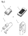
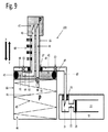
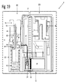
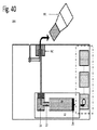
図1は、いくつかの実施形態による、インスリン送達システム100の構成要素を示す。システムは、以下の構成要素のうち、つまり、インスリンパッチポンプ1(ポンプ、物質送達ポンプ、薬物送達ポンプ、および同種のもの)、コントローラ2、充電器3、および支援デバイス4の少なくとも一つ(およびいくつかの実施形態では、二つ以上、およびいくつかの実施形態では、全て)を含む。いくつかの実施形態では、コントローラ2はパッチポンプ1に遠隔に命令し、警告および警報をパッチポンプ1から受信する。コントローラ2は、タッチスクリーンおよび操作ボタンなどのユーザインターフェースを含むことができる。コントローラ2はまた、他の薬物/糖尿病管理デバイス(例えば、グルコースメーター)、BLE有効デバイス(PC、スマートフォン、タブレットなど)およびクラウドと通信し得る。さらに、いくつかの実施形態では、コントローラはスマートフォンおよび同種のものを含み得る。
FIG. 1 shows the components of the
いくつかの実施形態では、パッチポンプ1は、再使用可能部品(RP)11および使い捨て部品(DP)12を含む。RP11は、駆動機構、電子機器、および電源(例えば、電池)のうちの一つまたは複数を含むことができる(機器によっては、そのうちの二つまたはそれ以上または全てを含むことができる)。DP12は、接着ベース、貯蔵部、ポンピング機構、充填ポート、出口ポート、およびカニューレの全てまたは複数を含み得る。
In some embodiments, the
インスリン(および/または別の薬物または物質)は、貯蔵部から出口ポートへ、および(いくつかの実施形態では)カニューレを通して出口ポートから身体へと送達するように構成され得る。RP11内(いくつかの実施形態では、DPに含まれてもよく、また一回きりの使用電池)の電源は、充電器3で充電され得る。支援デバイス4は、RP11およびDP12を接続し、貯蔵部を充填すること、パッチポンプ1を皮膚に接着すること、およびカニューレ挿入のうちの少なくとも一つに使用され得る。カニューレ挿入後、支援デバイス4を廃棄することができる。
Insulin (and / or another drug or substance) may be configured to be delivered from the reservoir to the exit port and (in some embodiments) from the exit port to the body through a cannula. The power source in the RP 11 (which may be included in the DP in some embodiments and is a one-time use battery) can be charged by the
図2は、いくつかの実施形態による、パッチポンプ1の接続されていない主要構成要素(RP11およびDP12)を示す。示されるように、DP12は、接着ベース40、貯蔵部20、および投薬部30を含む。インスリンは、貯蔵部20から投薬部30へ、およびカニューレ(図示せず)を通して投薬部30からユーザの身体へと送達され得る。いくつかの実施形態によれば、動作前に、ユーザはRP11およびDP12を接続し(パッチポンプ1を形成する)、貯蔵部20を充填し、パッチポンプ1を皮膚に接着させ、カニューレ(図示せず)を挿入する。動作サイクル(パッチポンプ取り付けからパッチポンプ取り外し、すなわち、約1〜5日間)の終了時、ユーザはパッチポンプ1を皮膚から取り外し、RP11をDP12から切り離し、DP12を配置する。いくつかの実施形態では、パッチポンプが、一つのRP11が動作しているとき(DPに接続され、ユーザ身体に接着される)、第二のRP11が充電されるように、少なくとも二つのRP11を含む、キット内に提供され得る。従って、一つの動作サイクルの終了時に、新しいDP12が充電されたRP11(第二のRP)に接続され、使用済みRP(第一のRP)が充電される。
FIG. 2 shows the unconnected major components (RP11 and DP12) of
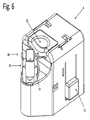
図3は、いくつかの実施形態による、支援デバイス4の空間図を示す。支援デバイス4は、バイアルコネクタ80、RPノッチ70、トリガー52、安全キャッチ51のうちの少なくとも一つ(およびいくつかの実施形態では、二つ以上、およびいくつかの実施形態では全て)を含み得る。一つの好ましい実施形態では、DP(貯蔵部20および接着ベース40)は、支援デバイス4の底部側にあらかじめ組み立てられる。接着ベース40は、二つの接着/粘着性表面と、パッチポンプ1を皮膚に接着するための底面と、DP12をRP11に固定するための上面(例えば、DP−RP接続後)とを含み得る。支援デバイス4は、貯蔵部充填機構(図5における200)、カニューレ挿入機構(図5の図300)、およびDR−RP整列機構のうちの少なくとも一つを含み得る。挿入機構は、トリガー52および安全キャッチ51(一方の側のみが示される)を付随して加圧することによって起動され得る。貯蔵部充填機構は、インスリンバイアルのバイアルコネクタ80への接続およびバイアルコネクタ80に対してバイアルを押すことにより、起動される。RPノッチ70は、RP−DP接続中にRP11とDP12間の整列を提供するように構成され得る。RP11(図示せず)は、貯蔵部20の上を摺動し、支援デバイス4内のDP12に接続するように構成され得る。
FIG. 3 shows a spatial view of the
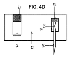
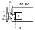
図4A〜Dは、いくつかの実施形態による、パッチポンプおよびDP12(B−D)の断面図を示す。図4Aは、例えば、RP11(一点鎖線)およびDP12を含むパッチポンプ1を示す。DP12は、貯蔵部20、貯蔵部プランジャ21、投薬部30、投薬部プランジャ31、充填用導管22、充填ポート隔壁23、充填ポートウェル24、出口ポート導管32、出口ポートウェル34、カニューレ36、カニューレ隔壁33、カニューレ開口部35、および貯蔵部−投薬部導管37の少なくとも複数の複数(いくつかの実施形態では、全て)を含み得る。
4A-D show cross-sectional views of the patch pump and DP12 (BD) according to some embodiments. FIG. 4A shows
貯蔵部20の充填(この場合、インスリンであるが、ユーザの組織への送達のための任意の物質であり得る)は、指定された注射器(図示せず)、または支援デバイス4(図3および図5〜19)を用いて行うことができる。注射器で、ユーザはインスリンをバイアルから引き、充填ポート隔壁23を注射器の針で穿孔し、充填ポートウェル24の中へインスリンを注入して、充填用導管22を通して、貯蔵部20にいれる(例えば、注射器は、バイアルからパッチポンプ貯蔵部20へのインスリン送達のための「輸送ツール」である)。支援デバイス4で、インスリンはバイアルからパッチポンプ貯蔵部20(「搬送ツール」なし)に直接送達され、インスリンは充填ポート隔壁23を通して充填ポートウェル24に送達され、充填用導管22を通して貯蔵部20内に送達される。
The filling of the reservoir 20 (in this case insulin, which can be any substance for delivery to the user's tissue) is a designated syringe (not shown), or assistive device 4 (FIG. 3 and). This can be done using FIGS. 5-19). With a syringe, the user draws insulin from the vial, pierces the filling
バイアルから引き出され、貯蔵部20に注入されるインスリンの量は、ユーザのインスリンの毎日の摂取および予測される使用日に依存することができる。例えば、毎日の摂取が50単位/日(50U/日)で、交換サイクル(交換の間の時間)が3日である場合、必要なインスリン量は150U(50Ux3日)である。インスリンはウェル24から充填用導管22を通して貯蔵部20内に送達される。貯蔵部20の充填中に、貯蔵部プランジャ21は、太字の矢印の方向にその最終的な位置(下向きの対角線)に変位される。貯蔵部プランジャ21の最終位置は、ユーザが貯蔵部20内に注入するインスリンの量に依存するように構成される。図4Aでは、貯蔵部は四つの目盛り(50U、100U、150U、および200U)でマークされてもよく、貯蔵部は150Uで充填され、貯蔵部プランジャ21の最終位置(下向きの対角線)は150Uのマークである。
The amount of insulin withdrawn from the vial and injected into the
パッチポンプ1の動作中、投薬部プランジャ31は、RP駆動機構(図示せず)によって後方および前方に変位されるように構成され得る。投薬部プランジャ31が後方に変位すると、インスリンは貯蔵部投薬部導管37を通して投薬部30内に送達され得る。投薬部プランジャ31が前方に変位されると、インスリンは投薬部30から、出口ポート導管32、出口ポートウェル34、カニューレ開口部35、およびカニューレ36を通して、ユーザの身体へと送達され得る。
During the operation of the
図4B、4C、および4Dは、それぞれ断面平面(点線)y−y(4B)、z−z(4C)、およびx−x(4D)を通るDP12の断面図を示す。図4Bは、図4Aの平面y−yの長軸方向の断面図を示す。DP12は、貯蔵部20、貯蔵部プランジャ21(充填前、黒色、充填後150Uのインスリンで下向きの対角線)、充填用導管22、充填ポート隔壁23、および充填ポートウェル24を含む。図4Cは、図4Aの平面z−zの長手方向断面図を示す(カニューレ36挿入後)。DP12は、投薬部30、投薬部プランジャ31、出口ポート導管32、出口ポートウェル34、カニューレ36、カニューレ隔壁33、およびカニューレ開口部35を含む。ユーザへのインスリン投与の間、インスリンは投薬部30から、出口ポート導管32、出口ポートウェル34、カニューレ開口部35、およびカニューレ36を通して、ユーザの身体へと送達され得る。カニューレ36(図5)の挿入前に、カニューレ隔壁33およびカニューレ開口部35はDP12の外側に位置し、カニューレ36先端はDP12内に位置する。いくつかの実施形態では、DP12は、支援デバイス(図3、5〜8、および19)とともにあらかじめ組み立てることができ、貯蔵部20の充填およびDP−RP接続(支援デバイス内)の後、パッチポンプ1が支援デバイスでユーザの皮膚に接着され、カニューレ36が、カニューレ挿入機構の作動によって挿入される(図19)。
4B, 4C, and 4D show cross-sectional views of DP12 passing through the cross-sectional planes (dotted line) yy (4B), zz (4C), and xx (4D), respectively. FIG. 4B shows a cross-sectional view of the plane yy of FIG. 4A in the long axis direction. The
いくつかの実施形態では、カニューレ挿入中に、カニューレ36およびカニューレ開口部35は、図4Cに示す位置に下向きに変位され、カニューレ隔壁33は出口ポートウェル34を密封し、カニューレ開口部35は出口ポートウェル34の中に位置し、カニューレ36の先端はDP12の底部の下に位置する。図4Dは、図4Aの平面x−xの横方向断面図を示す。DP12は、充填ポート隔壁23、充填ポートウェル24、出口ポートウェル34、カニューレ36、カニューレ隔壁33、およびカニューレ開口部35を含む。
In some embodiments, during cannulation, the
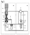
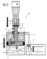
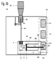
図5は、支援デバイス4および予め組み立てられたDP12の主要構成要素のスキームを示す。いくつかの実施形態では、支援デバイス4には、貯蔵部充填機構200およびカニューレ挿入機構300のうち少なくとも一つが含まれ得る。別の実施形態では(図示せず)、インスリン充填およびカニューレ挿入は、二つの分離したデバイス、つまり、充填デバイスおよび挿入デバイス(インサータ)を用いて実施でき、各デバイスは別個のハウジングを有することができる(およびいくつかの実施形態では別個のハウジングを有する)。充填デバイスは貯蔵部充填機構200で構成することができ、挿入デバイスはカニューレ挿入機構300を有する。以下、本開示の少なくとも一つおよび/または別の実施形態に関する貯蔵部充填機構200は、交換可能に、支援デバイス4(挿入機構300を含む)、または別個のハウジングおよび別個の貯蔵部充填機構200を有するスタンドアロンの充填デバイスの一部とし得る。
FIG. 5 shows a scheme of the main components of the
図5に示す支援デバイス4は、予め組み立てられたDP12、貯蔵部充填機構200、およびカニューレ挿入機構300を含む。貯蔵部充填機構200は、バイアルアダプタ41、充填針43、通気針44、充填ピストン42、充填空所48、搬送針47、ピストンバネ45、および通気開口部46のうちの少なくとも一つ(および、いくつかの実施形態では、二つ以上、およびいくつかの実施形態では、全て)を含んでもよい。カニューレ挿入機構300は、トリガー52、インサータバネ69、およびインサータハンマー54を含み得る。DP12は、充填ポート隔壁23、充填ポートウェル24、出口ポートウェル34、カニューレ36、カニューレ隔壁33、およびカニューレ開口部35を含み得る。従って、カニューレ挿入後、カニューレ隔壁33は、出口ポートウェル34を密封するように構成され、カニューレ開口部35は出口ポートウェル34内に位置し、カニューレ36の先端はDP12の底部の下に位置する(図4C)。図5は、空所48の充填フェーズ(フェーズ3、図8Aおよび12)の間の貯蔵部充填機構200を示し、バイアル50はバイアルアダプタ41に接続され、インスリンはバイアル50から空所48に送達される。搬送針47は、充填ポート隔壁23を貫通し、搬送針47の先端は充填ポートウェル34内に位置する。
The
図6、7A〜B、および8A〜Bは、いくつかの実施形態による、支援デバイス4(図6)の空間的図および貯蔵部充填機構(図7A〜Bおよび8A−B)の動作フェーズを示す。第一に、バイアル接続(7A)において、−バイアル50は、バイアルアダプタ41、第二の間隔充填(7B)に接続され、バイアルが下向きに押され、インスリンがバイアルから空所48に送達される。第三に、貯蔵部充填(8A)において、バイアル50から圧力が除去され、バイアル50が引き込まれ、インスリンが空所48から貯蔵部20へ送達される。第四に、バイアル切り離し(8B)において、バイアル50は支援デバイス4から取り外される。
6, 7A-B, and 8A-B show the spatial diagram of assistive device 4 (FIG. 6) and the operating phase of the reservoir filling mechanism (FIGS. 7A-B and 8A-B) according to some embodiments. Shown. First, in the vial connection (7A)-the
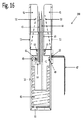
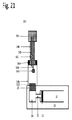
図6は、いくつかの実施形態による、支援デバイス4の空間図を示す。支援デバイス4は、トリガー52、安全キャッチ51、およびバイアルコネクタ80を含む。バイアルコネクタ80は、バイアルアダプタ41および針プロテクタ53を含んでもよい。
FIG. 6 shows a spatial view of the
図7Aは、いくつかの実施形態による、貯蔵部充填(バイアル接続)のフェーズ1での支援デバイス4の空間的図を示す。支援デバイスは、トリガー、52、安全キャッチ51、およびバイアルコネクタ80(バイアルアダプタ41および針プロテクタ53)を含む。貯蔵部充填のフェーズ1の間、バイアル50はバイアルアダプタ41に接続される(図10の動作スキーム)。
FIG. 7A shows a spatial view of the
図7Bは、いくつかの実施形態による、貯蔵部充填(空所充填)のフェーズ2での支援デバイス4の空間的図を示す。支援デバイスは、トリガー52、安全キャッチ51、およびバイアルコネクタ80(バイアルアダプタ41および針プロテクタ53)を含み得る。貯蔵部充填のフェーズ2の間、バイアル50は太字の矢印の方向に下方に、強制され得る。インスリンをバイアル50から空所48に送達することができる(図11の動作スキーム)。
FIG. 7B shows a spatial view of the
図8Aは、いくつかの実施形態による、充填プロセス(貯蔵部充填)のフェーズ3での支援デバイス4の空間的図を示す。支援デバイス4は、トリガー52、安全キャッチ51、およびバイアルコネクタ80(バイアルアダプタ41および針プロテクタ53)を含む。充填プロセスのフェーズ3の間、バイアル50は太字の矢印の方向に格納され得る。インスリンは、空所48から貯蔵部20へと送達される(図12の動作スキーム)。
FIG. 8A shows a spatial view of the
図8Bは、いくつかの実施形態による、充填プロセス(バイアル切り離し)のフェーズ4での支援デバイス4の空間的図を示す。支援デバイス4は、トリガー52、安全キャッチ51、およびバイアルコネクタ80(バイアルアダプタ41および針プロテクタ53)を含む。充填プロセスのフェーズ4の間、バイアル50は支援デバイス4から取り外される(図13の動作スキーム)。
FIG. 8B shows a spatial view of the
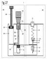
図9〜14は、いくつかの実施形態による、支援デバイス4(図9)の貯蔵部充填機構200のスキーム、および貯蔵部充填(図10〜14)の動作フェーズ(フェーズ1→フェーズ4)を示す。図9は、貯蔵部充填機構200の断面のスキームを示す。貯蔵部充填機構200は、バイアルアダプタ41、スライド式ロッド65、スライド式ロッド開口部67、充填針43、通気針44、充填ピストン42、充填空所48、ピストン導管64、搬送針47、ピストンガスケット49、空所ガスケット63、第一の一方向バルブ61、第二の一方向バルブ62、第三の一方向バルブ68、搬送針47、目盛りマーク60、充填スリーブ66、ピストンバネ45、および通気開口部46の複数、および好ましくは全てを含んでもよい。いくつかの実施形態では、貯蔵部充填機構200は、支援デバイス4(図示せず)内のDP12とあらかじめ組み立てられ得る。
9 to 14 show the scheme of the storage
DP12はまた、充填ポート隔壁23、充填ポートウェル24、充填用導管22、貯蔵部20、および貯蔵部プランジャ21の複数、および好ましくは全てを含んでもよい。搬送針47は、充填ポート隔壁23を貫通するように構成され、搬送針47の先端は充填ポートウェル24の中に存在する。バイアルアダプタ41は、円筒形状のスライド式ロッド65を介して充填ピストン42と接続され得る。充填スリーブ66は、ピストンバネ45のうちの複数、および好ましくは全てを含んでもよいシリンダ、充填ピストン42、通気開口部46、および充填スリーブ開口部67のうちの少なくとも一つ、およびいくつの実施形態では、複数、および、いくつの実施形態では、全てを含んでもよい。空所ガスケット63は、スライド式ロッド65が、充填スリーブ開口部67内で直線的に変位した時に(太字の矢印XおよびYの方向に)、空所48の密封を提供する充填スリーブ開口部67に接続され得る。充填ピストン42は、充填ピストン42が充填スリーブ66内で直線的に変位した時に、空所48の密封を提供するガスケット49を含み得る。太字の矢印Xの方向に充填ピストン42の変位は、空所48の容積を増加させ、ピストンバネ45を圧縮するように構成され、太字Y方向における充填ピストン42の変位は、空所48の容積を減少させ、ピストンバネ45を伸張させるように構成される。充填針43は、鋭利な先端を含み、スライド式ロッド65を横断することが好ましい。充填針43は、充填ピストン42を横断するピストン導管64を経由して、空所48と一方向の水圧連通を含み得る。
The
第一の一方向バルブ61は、充填針43の先端からピストン導管64を通って空所48へと一方向のインスリン送達を提供する。空所48は、搬送針47、充填ポートウェル24、貯蔵部充填用導管22、および貯蔵部20を介して、貯蔵部20との一方向の水圧連通を含むことが好ましい。第二の一方向バルブ62は、搬送針47、充填ポートウェル24および貯蔵部充填用導管22を介して、空所48から貯蔵部20への一方向のインスリン送達を提供することが好ましい。通気針44は、鋭利な先端を含み、スライド式ロッド65を横断することが好ましい。通気針44は、充填スリーブ66と通気針44の先端との間の空気連通を提供するように構成される。いくつかの実施形態では、ピストンスリーブ66内の通気針44の端部に配置され得る、第三の一方向バルブ68を提供することができる。第三の一方向バルブ68は、大気からバイアル50への一方向空気送達を提供するように構成されており、バイアル50内の圧力が大気圧超えている場合(例えば、バイアルが、貯蔵部充填用の注射器を使用して空気で充填された場合には、これが起こり得る)、不注意のインスリン送達を防止するように構成される。
The first one-
通気開口部46は、大気と充填スリーブ66との間の大気圧(P)平衡を提供するように構成される。バイアルがバイアルアダプタ41に接続されていない場合、通気針44の先端での圧力は大気圧(P)であり、通気針44に沿った空気移動はない。スライド式ロッド65は、動作サイクル(すなわち、1〜5日)中の必要なインスリン摂取量に従い、バイアル50から貯蔵部20に送達されるインスリンの容積の表示をユーザに提供する目盛りマーク60を使って構成されることが好ましい。図9は、50、100、150、および200のインスリン単位のマークの実施例を示す。充填プロセス中、ユーザはバイアル50を押し、バイアルアダプタ41およびスライド式ロッド65を太字の矢印Xの方向に移動させる。変位(スライド式ロッド65および充填ピストン42の直線的な移動)の程度は、バイアル50から貯蔵部20へ送達されるインスリンの量と相関するように構成される。例えば、必要な量が150ユニット(150U)である場合、ユーザはバイアル41およびスライド式ロッド65を150単位のマークのレベルに押す。別の実施形態では、貯蔵部充填機構200には、スライド式ロッド65上に位置付けられる容積設定ノブ(図示せず)が提供され得る。ユーザによる一方向または反対方向(例えば、時計回りまたは反時計回り)によるノブの回転は、それぞれ送達されるインスリン量を増加または減少させる。目盛りをノブ(つまり0U〜200U)にマークすることができる。ユーザは、容積設定ノブを望ましい量(すなわち、150単位)に回転させ、バイアル50を押す(図11)。別の好ましい実施形態では、バイアル50から貯蔵部20へ送達されるインスリンの量は、固定量(すなわち、50インスリン単位)に事前設定され得る。スライド式ロッド65の下向きの変位(太字X)の程度は、プリセットされてもよく、従って、一回の押しでバイアル50から貯蔵部20に送達されるインスリンの量は、プリセットされる。送達されたインスリンの総量=量(インスリン単位)×押した数、例えば、固定量が50単位(50U)であり、一つの交換サイクル(すなわち、1〜5日)に対するユーザ要求が150ユニット(150U)である場合、ユーザはバイアルを3回(50U×3=150U)を押すべきである。図9に示す実施例では、貯蔵部の最大容積が200Uである場合、それに応じて、フルな貯蔵を達成するために、最大の押す数は4(50U×4=200U)である。
The
図10は、いくつかの実施形態による、充填プロセス(バイアル接続)のフェーズ1での貯蔵部充填機構200の断面を示す。貯蔵部充填機構200は、バイアルアダプタ41、スライド式ロッド65、スライド式ロッド開口部67、充填針43、通気針44、充填ピストン42、充填空所48、ピストン導管64、搬送針47、ピストンガスケット49、空所ガスケット63、第一の一方向バルブ61、第二の一方向バルブ62、第三の一方向バルブ68、搬送針47、目盛りマーク60、充填スリーブ66、ピストンバネ45、および通気開口部46の複数、および好ましくは全てを含む。貯蔵部充填機構200は、搬送針47を通してバイアル50から(DP12内に存在する)貯蔵部20へのインスリンの送達を提供する。DP12は、充填ポート隔壁23、充填ポートウェル24、充填用導管22、貯蔵部20、および貯蔵部プランジャ21の複数、および好ましくは全てを含む。充填プロセスのフェーズ1で、バイアル50はバイアルアダプタ41に接続されている。充填針43および通気針44は、バイアルカバー55のゴム隔壁を貫通する。
FIG. 10 shows a cross section of the
図11は、いくつかの実施形態による、充填プロセス(空所充填)のフェーズ2での貯蔵部充填機構200の断面のスキームを示す。貯蔵部充填機構200は、バイアルアダプタ41、スライド式ロッド65、スライド式ロッド開口部67、充填針43、通気針44、充填ピストン42、充填空所48、ピストン導管64、搬送針47、ピストンガスケット49、空所ガスケット63、第一の一方向バルブ61、第二の一方向バルブ62、第三の一方向バルブ68、搬送針47、目盛りマーク60、充填スリーブ66、ピストンバネ45、および通気開口部46の複数、および好ましくは全てを含む。DP12は、充填ポート隔壁23、充填ポートウェル24、充填用導管22、貯蔵部20、および貯蔵部プランジャ21の複数、および好ましくは全てを含む。充填プロセスのフェーズ2で、バイアル50は太字の矢印の方向に押され、同時に、スライド式ロッド65および充填ピストン42が同じ方向(太字の矢印)に変位する。充填ピストン42の変位は、ピストンガスケット49および空所ガスケット63によって密封封止される空所48内の陰圧を作り出す。バイアル50内のインスリン(波状線)は、圧力勾配に従い、充填針43、ピストン導管64、および第一の一方向バルブ61を通って空所48の中へと破線矢印Xの方向に送達される。
FIG. 11 shows a cross-sectional scheme of the
図11の実施例では、スライド式ロッド65は150単位のマークに移動でき、従って、空所48はインスリンの150単位で充填される。充填ピストン42の変位の間、ピストンバネ45は圧縮される。第二の一方向バルブ62は、空気が空所内に入り、気泡を生成することを防止するように構成され得る。バイアル50から空所48内へのインスリン送達中に、バイアル50内の圧力は大気圧(P−)以下に低下する。バイアル内の圧力降下(P−)の後、空気は圧力勾配に従い、充填スリーブ66から通気針44を通って破線矢印Yの方向に送達され、オプションの第三のバルブ68を通ってバイアル50に送達される。充填フェーズ2の終了時に、バイアル50内の圧力は大気圧である。
In the embodiment of FIG. 11, the sliding
図12いくつかの実施形態による、充填プロセス(貯蔵部充填)のフェーズ3での貯蔵部充填機構200の断面のスキームを示す。貯蔵部充填機構200は、バイアルアダプタ41、スライド式ロッド65、スライド式ロッド開口部67、充填針43、通気針44、充填ピストン42、空所48、ピストン導管64、搬送針47、ピストンガスケット49、空所ガスケット63、第一の一方向バルブ61、第二の一方向バルブ62、搬送針47、目盛りマーク60、充填スリーブ66、ピストンバネ45、および通気開口部46の複数、および好ましくは全てを含む。DP12は、以下の複数、および好ましくは全てを含む。充填ポート隔壁23、充填ポートウェル24、充填用導管22、貯蔵部20、貯蔵部プランジャ21。充填プロセスのフェーズ3で、バイアル50上にユーザによって加えられる圧力が除去され、圧縮ピストンバネ45内で貯蔵されたエネルギーが解放される。充填ピストン42、スライド式ロッド65、およびバイアルアダプタ41は、太字の矢印の方向に変位される。充填ピストン42の移動は、空所48の容積を減少させるが、空所48に一時的に保存されたインスリンは、空所48から変位し、第二の一方向バルブ62、搬送針47、充填ポートウェル24、充填用導管22を通って破線矢印Xの方向に送達され、貯蔵部20内に送達される。貯蔵部20の充填中、貯蔵部プランジャ21は、貯蔵部20の後側に向かって薄い矢印の方向に変位される。第一の一方向バルブ61は、空所48からインスリンバイアルへの逆インスリン送達を防止するように構成され得る。バイアル50内の圧力(P)は、充填スリーブ66内の大気圧と等しいままである。
FIG. 12 shows a cross-sectional scheme of the storage
図13は、いくつかの実施形態による、充填プロセス(バイアル切り離し)のフェーズ4での貯蔵部充填機構200の断面のスキームを示す。貯蔵部充填機構200は、バイアルアダプタ41、スライド式ロッド65、充填針43、通気針44、充填ピストン42、空所48、ピストン導管64、搬送針47、ピストンガスケット49、空所ガスケット63、第一の一方向バルブ61、第二の一方向バルブ62、第三の一方向バルブ68、搬送針47、目盛りマーク60、充填スリーブ66、ピストンバネ45、および通気開口部46の複数、および好ましくは全てを含む。DP12は、充填ポート隔壁23、充填ポートウェル24、充填用導管22、貯蔵部20、および貯蔵部プランジャ21の複数、および好ましくは全てを含む。充填プロセスのフェーズ4では、バイアル50は取り外される(湾曲した太字の矢印)。取り外されたバイアル50内の圧力は大気圧と等しく、バイアル50は別の充填サイクルの準備ができている。
FIG. 13 shows a cross-sectional scheme of the
図14は、いくつかの実施形態による、充填プロセス完了後、およびカニューレ挿入およびユーザの皮膚90からの支援デバイス4の取り外し後の、DP12の断面のスキームを示す(カニューレ挿入機構、カニューレ挿入、およびカニューレは図示しない)。DP12はまた、接着ベース40、充填ポート隔壁23、充填ポートウェル24、充填用導管22、貯蔵部20、および貯蔵部プランジャ21の複数、および好ましくは全てを含んでもよい。貯蔵部20は充填され(揺り動かす)、貯蔵部プランジャ21は後部位置にある。貯蔵部は、150単位のインスリン(150U)(図10〜12で述べた実施例に示す)で充填される。
FIG. 14 shows a cross-sectional scheme of DP12 after completion of the filling process and after cannulation and removal of
図15〜16は、いくつかの実施形態による、貯蔵部充填機構200およびDP12(図15)およびスタンドアロン貯蔵部充填機構200(図16)の断面図を示す。図15は、貯蔵部充填機構200およびDP12の断面図を示す。貯蔵部充填機構200は、バイアルアダプタ41、針プロテクタ53、スライド式ロッド65、充填針43、通気針44、充填ピストン42、空所48、ピストン導管64、搬送針47、ピストンガスケット49、空所ガスケット63、第一の一方向バルブ61、第二の一方向バルブ62、搬送針47、充填スリーブ66、ピストンバネ45、および通気開口部46の複数、および好ましくは全てを含むことができる。DP12は、充填ポート隔壁23、充填ポートウェル24、充填用導管22、貯蔵部20、および貯蔵部プランジャ21の複数、および好ましくは全てを含む。針プロテクタ53は、帯の「葉」(例えば、一つまたは複数の葉)を有するペタル様のバネを含み得る。いくつかの実施形態では、四つの葉が、それぞれが「葉」(例えば、四つの葉)を含み、好ましくは剛直な葉(図6〜8の空間図)を含むバイアルアダプタ41内に配置される。バイアルアダプタ41は、針プロテクタ43に対して直線的に下方、および上方(太字の矢印XおよびY)を変位することができる。バイアルアダプタ41へのバイアル50の接続前に、針プロテクタの葉は充填針43および通気針44と平行である。バイアル50の取り外し後、針プロテクタ53の葉は、針43および44の両方の上に曲げるように再構成され、それによってユーザが不注意による自分を刺すのを保護する(図18)。
15-16 show cross-sectional views of the
図16は、いくつかの実施形態による、バイアル接続前の貯蔵部充填機構200の拡大断面図を示す。貯蔵部充填機構200は、バイアルアダプタ41、針プロテクタ53、スライド式ロッド65、充填針43、通気針44、充填ピストン42、空所48、ピストン導管64、搬送針47、ピストンガスケット49、空所ガスケット63、第一の一方向バルブ61、第二の一方向バルブ62、搬送針47、充填スリーブ66、ピストンバネ45、および通気開口部46の複数、および好ましくは全てを含む。針プロテクタ53の葉は、バイアル50の接続(連続線53)の前、およびバイアル50の分離(破線53)の後に示されている。
FIG. 16 shows an enlarged cross-sectional view of the storage
図17A〜Cは、いくつかの実施形態による、つまり、フェーズ1−バイアル接続(17A)、フェーズ2−空所充填(17B)、およびフェーズ3−貯蔵部充填(17C)による、充填プロセスの最初の三つのフェーズでの貯蔵部充填機構200の断面図を示す。図17A〜C(断面図)は、それぞれ図10〜12(スキーム)に対応する:図17Aは図10、図17Bは図11、および図17Cは図12に対応する。貯蔵部充填機構200は、バイアルアダプタ41、針プロテクタ53、スライド式ロッド65、充填針43、通気針44、充填ピストン42、空所48、ピストン導管64、搬送針47、ピストンガスケット49、空所ガスケット63、第一の一方向バルブ61、第二の一方向バルブ62、オプションの第三の一方向バルブ68(図示せず)、搬送針47、充填スリーブ66、ピストンバネ45、および通気開口部46の複数、および好ましくは全てを含む。図17Aは、充填プロセス(バイアル50接続)のフェーズ1を示す。バイアル50は、バイアルアダプタ41に接続され、充填針43および通気針44は、バイアルゴムシール(図10および11に示す)を穿孔し、充填針43および通気針の先端がバイアル含有量(すなわち、インスリン)と接触する。
17A-C show the beginning of the filling process according to several embodiments, ie, with Phase 1-Vial connection (17A), Phase 2-Vacancy filling (17B), and Phase 3-Reservoir filling (17C). The cross-sectional view of the storage
図17Bは、いくつかの実施形態による、充填プロセス(空所48充填)のフェーズ2を示す。バイアル50は、ユーザによって太字の矢印(下方)の方向に、貯蔵部内で充填されるインスリンの所望量に対応する量に押される量に、押される(すなわち、必要な量が150Uの場合、バイアルは150Uマークに近づくまで押されるべきである)(図11)。スライド式ロッド65および充填ピストン42は、太字の矢印の方向に変位され、ピストンバネ45は圧縮される。インスリンは、充填針43、ピストン導管64、および第一の一方向バルブ61を介して空所48内にバイアル50から送達される。空気は圧力勾配に従い、充填スリーブ66(大気圧)からバイアル50(サブ大気圧)まで通気針44を通して送達される。空所充填フェーズの終了時に、空所48は望ましい量のインスリンで充填され、バイアル50内の圧力は大気圧である。図17Cは、充填プロセスのフェーズ3を示し、これは貯蔵部の充填も含む。従って、バイアル50からの圧力が取り除かれ、充填ピストン42、スライド式ロッド65、およびバイアルアダプタ41は、太字の矢印(フェーズ1の間にピストンバネ45に保存されたエネルギーの解放)の方向に変位する。空所48の容積は減少され、インスリンは、第二の一方向バルブ62および搬送針47を介して空所48から貯蔵部(図15)へと移動する。
FIG. 17B shows
図18は、いくつかの実施形態による、充填プロセスが完了し、バイアルが切り離された後の貯蔵部充填機構200の拡大断面図を示す。貯蔵部充填機構200は、バイアルアダプタ41、針プロテクタ53、スライド式ロッド65、充填針43、通気針44、充填ピストン42、空所48、ピストン導管64、搬送針47、ピストンガスケット49、空所ガスケット63、第一の一方向バルブ61、第二の一方向バルブ62、搬送針47、充填スリーブ66、ピストンバネ45、および通気開口部46の複数、および好ましくは全てを含む。ペタル様のバネ(針プロテクタ53)の葉は、充填針43および通気針44の上に曲がり、ユーザが不注意による自分を刺すのを保護する。針プロテクタ53のバネの葉は、直線の位置(充填針43、通気針44およびバイアルアダプタ41と平行)にあらかじめロードされ、バイアル変位後にそれらのプリセットされた形状(バネはアンロードされる)を再開する。
FIG. 18 shows an enlarged cross-sectional view of the
図19は、貯蔵部充填機構200、カニューレ挿入機構300、およびDP12のいくつかの構成要素を含む支援デバイス4の横断面図を示す。貯蔵部充填機構200(破線)は、バイアルアダプタ41、針プロテクタ53、スライド式ロッド65、充填針43、通気針44、充填ピストン42、空所48、ピストン導管64、搬送針47、ピストンガスケット49、空所ガスケット63、搬送針47、充填スリーブ66、ピストンバネ45、および通気開口部46の複数、および好ましくは全てを含む。カニューレ挿入機構300(破線)は、トリガー52およびインサータバネ69(その他の部品が図示されていない)の複数、および好ましくは全てを含む。DP12は、充填ポート隔壁23、充填ポートウェル24、貯蔵部20、および貯蔵部プランジャ21の複数、および好ましくは全てを含む。バイアルアダプタ41、充填針43の先端、および通気針44の先端は、トリガー52への自由なアクセスを提供するトリガー52の下に配置されることが好ましい。
FIG. 19 shows a cross-sectional view of the
図20は、図4に示す平面XXに沿った支援デバイス401の断面を示す。支援デバイス401は、カニューレ挿入機構300および貯蔵部充填機構201を含む。いくつかの実施形態による、貯蔵部充填機構201は、バイアルアダプタ541、プランジャ548、通気針543、充填針544、充填針キャップ545、およびシリンダ546を含む。
FIG. 20 shows a cross section of the support device 401 along the plane XX shown in FIG. The assist device 401 includes a
充填針544および通気針543は、プランジャ548の本体を通して走り、その端部はプランジャの先端から突出する。プランジャ548の第一の端部550は、バイアルアダプタ541と接続され得る。通気針543の第一の端部および充填針544の第一の端部は、両方ともプランジャ548の第一の端部550からバイアルアダプタ541の内部へと突出し得る。さまざまな実施形態によるさまざまな他の特徴は、以下の機能/構造/明瞭化を含み得る。
− プランジャ548の第二の端部は、シリンダ546内に摺動可能にまたはその他の方法で嵌合するように構成され得る。プランジャ548とシリンダ546との間の気密シールは、ガスケット549によって確立され得る。シリンダ546の閉鎖端は、隔壁552を使って構成され得る。
− 充填および通気針は、鋼、またはプラスチックなどの金属から作製され得る。充填用針および通気針は、両端の鋭利な先端を使って構成され得る。
− バイアルアダプタ541は、バイアル501を可逆的に受けるように構成され得る。バイアルアダプタ541にバイアル501が配置されるときはいつでも、バイアルアダプタの隔壁は通気針543の第一の端部および充填針544の第一の端部によって貫通される。
− 通気針543は、空気がシリンダ546の内部からバイアル501の内部へ流れることを可能にする一方向バルブ547を使って構成され得る。
および/または
− 充填針544の第二の端部には、充填針キャップ545が設けられ得る。充填針キャップ545はプラスチック製であり得る。充填針キャップ545は、充填針544の第二の先端を封止するように構成され得る。
The filling
-The second end of the
-Filling and venting needles can be made of metal such as steel or plastic. Filling needles and vent needles can be constructed with sharp tips at both ends.
-The
-The
And / or-A
図21〜26を参照し、いくつかの実施形態による、図4の平面YYに沿った動作中の貯蔵部充填機構201の断面を示す。貯蔵部充填機構201は、シリンダ546の隔壁552が充填ポート隔壁23に隣接またはそれと接触するように、支援デバイス401内に構成され得る(図21)。いくつかの実施形態による、貯蔵部充填機構401を使用したポンプ使い捨て部品12の充填貯蔵部20の第一の工程では、通気針543の第一の先端および充填針544の第一の先端がバイアル501の隔壁を貫通するように、バイアル501をバイアルアダプタ541に配置する(図22)。従って、バイアルアダプタ541にバイアル501の配置の後、シリンダ546の内部からの空気は、通気針543を通ってバイアル501の内部へと流れ得る。最初に、シリンダ543内の圧力は大気圧Pであり得る。充填ポートウェル24、充填用導管22の内部の圧力、および貯蔵部プランジャ21の外部の圧力は、大気圧Pであり得る。バイアル501内の圧力はPより大きいか同じであっても良い。バイアル501は、最初、空気(図示せず)またインスリンの容積を含んでもよい。プランジャ548の端550は、最初はシリンダ546の開放端付近に配置され得る。
With reference to FIGS. 21-26, a cross section of the storage
第二の工程(図23)において、ユーザはシリンダ546の閉鎖端の方向に下方にバイアル501を押し、それによってプランジャ548の端部550をシリンダ546の閉鎖端に向かって押す。その結果、シリンダ546の内部に閉じ込められた空気の容積が減少し、その空気が圧縮される。シリンダ546の内部内の空気圧はP+>Pに増加する。シリンダ546の内部がバイアル501の内部と流体連通しているため、バイアル501内のインスリンはP+に加圧される。プランジャ543は、充填針キャップ545がシリンダ隔壁552と接触する位置にシリンダ546内を進み得る。
In the second step (FIG. 23), the user pushes the
第三の工程(図24)において、ユーザはシリンダ546の閉鎖端の方向にバイアル501を押し続ける。充填針544は、充填針キャップ545、シリンダ隔壁552および充填ポート隔壁23を貫通する。充填針544の第二の先端が充填ポート隔壁23を出て充填ウェル24の中へ入ると、バイアル501の内部と充填ウェル24の間に流体連通が確立される。バイアル501中の圧力P+は充填ウェル24中の大気圧Pよりも大きいため、インスリンはバイアル501からウェル24へ流れ始め、空気は通気ニードル543を通してシリンダ546の内部からバイアル501に流れ始める(図25)。一方向バルブ547は、インスリンまたは空気のバイアル501からシリンダ546への逆流を防止し得る。圧力P+は、充填ウェル24および充填用導管22で確立されている。その結果、貯蔵部プランジャ21は後方に移動し、およびインスリンは、貯蔵部20に入る(図25)。インスリンは、バイアル501およびウェル24の圧力が大気圧に等しくなるまで、貯蔵部を満たす(図26)。その後、バイアル501はバイアルアダプタ541から取り外され、充填プロセスが完了する。
In the third step (FIG. 24), the user continues to push the
図27は、図4に示す平面XXに沿った支援デバイス402の断面を示す。支援デバイス402は、カニューレ挿入機構300および貯蔵部充填機構202を含む。貯蔵部充填機構202は、バイアルアダプタ641、プランジャ648、通気針643、充填針644、シリンダ646、および一方向バルブ651を随意に装備し得る導管647を含む。充填針644および通気針643は、バイアルアダプタ641の底端650から突出してバイアル601の隔壁を穿孔し、バイアル601の内部と連通するように構成され得る。通気針643は、導管647と流体連通してもよく、導管647は、シリンダ646の内部と流体連通し得る。バルブ651は、シリンダ646の内部から通気針643への導管647を通して空気の流れを可能にすることができ、それでもなお、空気またはインスリンの流れが逆方向になることを防止する。充填針644は、初めに、充填ポート隔壁23を横切って配置され、それによってバイアル601の内部と充填ウェル24の間の流体連通が可能となり得る。プランジャ648は、シリンダ646内に摺動可能に嵌合するように構成され得る。プランジャ648とシリンダ646との間の気密シールは、ガスケット649によって確立され得る。その他の機能/特徴/明確化には以下が含まれる。
− 充填および通気針は、鋼、またはプラスチックなどの金属から作製され得る。充填用針および通気針は、両端の鋭利な先端を使って構成され得る。
および/または
− バイアルアダプタ641は、バイアル601を可逆的に受けるように構成され得る。バイアル601がバイアルアダプタ641内に配置されるときはいつでも、バイアルアダプタの隔壁は、通気針643の第一の端部および針644の第一の端部によって貫通される。
FIG. 27 shows a cross section of the support device 402 along the plane XX shown in FIG. The assist device 402 includes a
-Filling and venting needles can be made of metal such as steel or plastic. Filling needles and vent needles can be constructed with sharp tips at both ends.
And / or − The
図28〜図31を参照し、いくつかの実施形態による、図4の平面YYに沿った動作中の貯蔵部充填機構202の断面を示す。最初に、プランジャ648は、ガスケット649がシリンダの開口部652の近くであるように、シリンダ646内に配置される(図28)。いくつかの実施形態による、貯蔵部充填機構202を使用したポンプ使い捨て部品12の充填貯蔵部20の第一の工程では、通気針643の先端653および充填針644の第一の先端654がバイアル601の隔壁を貫通するように、バイアル601をバイアルアダプタ641に配置する(図29)。従って、バイアルアダプタ641にバイアル601を配置した後、シリンダ646の内部からの空気は、通気針643を通ってバイアル601の内部へと流れ得る。最初に、シリンダ643内の圧力は大気圧Pであり得る。充填ポートウェル24、充填用導管22の内部の圧力、および貯蔵部プランジャ21の外部の圧力は、大気圧Pであり得る。バイアル601内の圧力はPより大きいか同じであっても良い。バイアル601は、最初、空気(図示せず)またインスリンの容積を含んでもよい。
With reference to FIGS. 28-31, a cross section of the
第二の工程(図30)において、ユーザは、シリンダ646の閉鎖端の方向にプランジャ648を下向きに押す。その結果、シリンダ646の内部に閉じ込められた空気の容積が減少し、その空気が圧縮される。シリンダ646の内部内の空気圧はP+>Pに増加する。シリンダ646の内部がバイアル601の内部と流体連通しているため、バイアル601内のインスリンはP+に加圧される。インスリンは、バイアル601から充填ウェル24および充填用導管22へと流れ、これによってP+に加圧される。貯蔵部プランジャ21にわたる圧力差の結果、貯蔵部プランジャは貯蔵部20内で後方に移動し、これによってインスリンで充填される。バイアル601からシリンダ646へのインスリンの流れは、任意の一方向バルブ651によって防止されるが、これは特にバイアル601が最初に加圧された場合に必要である。貯蔵部がインスリンで完全に充填されるまで(貯蔵部20には、プランジャ21が貯蔵部の内部から出るのを防ぐストッパーを装備できる)、またはプランジャ648の端部656がシリンダ646の閉鎖端655に到達するまで(図31)、またはバイアル601内の圧力が大気圧Pと等しくなるまで、プロセスは続行する。貯蔵部20内のインスリンのレベルを測定するセンサは、貯蔵部内のインスリンの望ましいレベルに達すると、ユーザに表示を提供し得る。その後、バイアル601はバイアルアダプタ641から取り外され、充填プロセスが完了する(図32)。
In the second step (FIG. 30), the user pushes the
図33は、図4に示す平面XXに沿った支援デバイス403の断面を示す。支援デバイス403は、デバイス402のような手動の凹部の代わりに、シリンダ内のプランジャを押圧する自動機構を含むことを除いて、支援デバイス402と類似している。 FIG. 33 shows a cross section of the support device 403 along the plane XX shown in FIG. The assist device 403 is similar to the assist device 402, except that it includes an automatic mechanism that presses the plunger in the cylinder instead of a manual recess like the device 402.
デバイス403は、カニューレ挿入機構300および貯蔵部充填機構203を含む。貯蔵部充填機構203は、バイアルアダプタ741、プランジャ748、通気針743、充填針744、シリンダ746、および一方向バルブ751を随意に装備し得る導管747を含む。充填針744および通気針743は、バイアルアダプタ741の底端750から突出してもよく、バイアル701の隔壁を穿孔するように構成され、バイアルの内部と連通するように構成され得る。通気針743は、導管747と流体連通してもよく、導管747は、シリンダ746の内部と流体連通し得る。バルブ751は、シリンダ746の内部から通気針743への導管747を通る空気の流れを可能にすることができ、それでもなお、空気またはインスリンの流れが逆方向になることを防止する。充填針744は、初めに充填ポート隔壁23を横切って配置され、それによってバイアル701の内部と充填ウェル24の間の流体連通が可能となり得る。プランジャ748は、シリンダ746内に摺動可能に嵌合するように構成され得る。プランジャ748とシリンダ746との間の気密シールは、ガスケット749によって確立され得る。
Device 403 includes a
充填および通気針は、ステンレスまたはプラスチックなどの金属から作製され得る。充填用針および通気針は、両端の鋭利な先端を使って構成され得る。 Filling and venting needles can be made from metals such as stainless steel or plastic. Filling needles and vent needles can be constructed with sharp tips at both ends.
バイアルアダプタ741は、バイアル701を可逆的に受けるように構成され得る。バイアルアダプタ741内にバイアル701が配置されるときはいつでも、バイアルアダプタの隔壁は、通気針743の第一の端部および針744の第一の端部によって貫通される。
The
充填機構203は、駆動機構770を含み得る。駆動機構は、電源771、コントローラ772、モータ773、およびギア774を含み得る。電源は、例えば、一回使用の電池または再充電可能電池とし得る。制御ユニットは、マイクロプロセッサおよびメモリを含むマイクロコンピュータであり得る。モータは、ブラシモータ、ブラシレスモータ、またはステッピングモータなどの直流モータであり得る。電源は、支援デバイス403に存在するインスリンポンプの電池であってもよく、コントローラはポンプのコントローラであり得る。ギアは、例えば、親ネジまたはラックの手段によってプランジャに結合され得る。駆動機構770は、操作ボタンなどの入力デバイスも含み得る。
The
動作中、充填機構203は、充填機構202と同様の方法で機械的に機能する。従って、機械の詳細な説明は省略される。しかし、機構203では、シリンダ746におけるプランジャ748の押し下げは、駆動機構770の動作によってもたらされる。バイアルアダプタ741へのバイアル701の接続に際して、ユーザは、駆動機構770に指示し、入力/出力デバイスを介してシリンダ746内のプランジャ748を押下する。別の方法として、光学センサなどのセンサは、アダプタへのバイアルの接続を検知してもよく、その後、駆動機構770に自動的に指示し、プランジャ748を押下する。ユーザまたはセンサからの命令は、電源771からモータ773へ電圧を供給し得るコントローラ772に送達され得る。モータ773は、ギア774によってシリンダ746においてプランジャ748を押下させ、それによって機構202に対して以前に記述されたように、インスリンをバイアル701から充填ウェル24およびポンプ貯蔵部に送達させる。
During operation, the
図34は、図4に示される平面XXに沿った支援デバイス404の断面を示す。デバイス404は、カニューレ挿入機構300および貯蔵部充填機構204を含む。図35は、図4に示す平面ZZに沿った充填機構204の断面を示す。
FIG. 34 shows a cross section of the support device 404 along the plane XX shown in FIG. Device 404 includes a
図34を参照する。いくつかの実施形態では、貯蔵部充填機構204は、バイアルアダプタ841、通気針843、充填針844、および一方向バルブ851を随意に装備し得る導管847を含む。充填針844および通気針843は、バイアルアダプタ841の底端850から突出してもよく、バイアル801の隔壁を穿孔するように構成され、バイアルの内部と連通し得る。通気針843は、導管847と流体連通してもよく、導管847は、大気と流体連通し得る。オプションのバルブ851は、導管847を通して、大気から通気針843への空気の流れを可能にすることができ、それでもなお、空気またはインスリンの流れが逆方向になることを防止する。充填針844は、初めに充填ポート隔壁23を横切って位置付けられ、それによってバイアル801の内部と充填ウェル24との間の流体連通が可能となり得る。
See FIG. 34. In some embodiments, the
図35を参照する。いくつかの実施形態では、貯蔵部充填機構204は、駆動機構870および連結ストリングをさらに含み得る。駆動機構は、電源871、コントローラ872、モータ873、およびリール874を含み得る。電源は、例えば、一回使用の電池または再充電可能電池とし得る。制御ユニットは、マイクロプロセッサおよびメモリを含むマイクロコンピュータであり得る。モータは、ブラシモータ、ブラシレスモータ、またはステッピングモータなどの直流モータであり得る。電源は、支援デバイス404に存在するインスリンポンプの電池であってもよく、コントローラはポンプのコントローラであり得る。駆動機構770は、操作ボタンなどの入力デバイスも含み得る。連結ストリング880は、リール874に接続された第一の端部881、および貯蔵部プランジャ21に接続された第二の端部882を有し得る。ストリング880は、その遠位端882付近のニック883を使って構成され得る。貯蔵部20は、その開放端885付近に配置されたストッパー884を使って構成され得る。ストリング880は、貯蔵部プランジャ882を引き込むために十分である駆動機構870によって加えられる引っ張り力を伝達するが、貯蔵部プランジャがストッパーに対してストリングによって引っ張られる際に、ニック883で破断するように構成され得る。
See FIG. 35. In some embodiments, the
いくつかの実施形態による、図4のZZ平面に沿って動作中の支援デバイス404の断面を図示する図35〜40を参照する。操作の第一の工程(図35)において、バイアルアダプタ841は空であり、貯蔵部プランジャ21は充填用導管22の近傍の貯蔵部端にある。第二の工程(図36)において、ユーザはバイアルアダプタ841にバイアル801を挿入する。充填針843の第一の端部は、バイアル801の隔壁を貫通し、それによってバイアルの内部と大気の間の流体連通を可能にする。充填針844の第一の端部はまた、バイアル801の隔壁を貫通する。充填針844の第二の端部は、充填ポート隔壁23を横断し、それによってバイアル801の内部、充填ポートウェル24および充填ポート導管22の間の流体連通を可能にする。第三の工程(図37)では、ユーザは、駆動機構に指示し、貯蔵部をインスリンで充填する。命令は、入力デバイスを介して提供され得る。別の方法として、光学的または機械的センサなどのバイアルアダプタのセンサは、バイアルアダプタ841内のバイアル801の存在を検出し、駆動機構に自動的にインスリン充填を開始するよう指示し得る。ユーザまたはセンサからの命令は、その後電源871からモータ873へ電圧を供給し得るコントローラ872に送達され得る。モータは、リール874を湾曲した矢印(反時計回り)の方向に回転させて、それによって直線矢印(右)の方向に連結ストリング880を引いてもよい。従って、ストリングは貯蔵部プランジャ21をストッパー884に向かって移動させ、それによってバイアル801の内部に陰圧を形成する。従って、インスリンはバイアルから貯蔵部へと流れる。大気からの空気は、通気針843を通しておよび随意にバルブ851を通ってバイアル801に流れ、それによってバイアルにおいて貯蔵部に供給されるインスリンを置換させる。このプロセスは、貯蔵部プランジャ21が、貯蔵部充填の終了を示すストッパー884に達するまで続けることができる(図38)。駆動機構は、ストリング880がニック883で破断するまで、ストッパー884に対してストリング880引き続ける(図39)。この時点で、駆動機構870は、リール874を、例えば、モータ電流センサからの命令、またはモータ回転カウンターによって回転させることを中止する。バイアル801は、充填プロセスを完了するバイアルアダプタ841から取り外され得る(図40)。
See FIGS. 35-40, which illustrates a cross section of the assist device 404 in operation along the ZZ plane of FIG. 4 according to some embodiments. In the first step of operation (FIG. 35), the
図41は、いくつかの実施形態による、図4に示される平面XXに沿った支援デバイス405の断面を示す。支援デバイス405は、カニューレ挿入機構300および貯蔵部充填機構205を含む。貯蔵部充填機構205は、機構201のシリンダ546およびプランジャ548が充填機構205内の蛇腹949と置き換えられることを除いて、デバイス401の貯蔵部充填機構201と類似している。
FIG. 41 shows a cross section of the support device 405 along plane XX shown in FIG. 4 according to some embodiments. The assist device 405 includes a
貯蔵部充填機構205は、バイアルアダプタ941、シャフト948、通気針943、充填針944、充填針キャップ945、および折り畳み可能な蛇腹949を含む。充填針944および通気針943は、シャフト948の本体を通して走り、その端部はシャフトの先端から突出する。シャフト948の第一の端部950は、バイアルアダプタ941と接続され得る。通気針943の第一の端および充填針944の第一の端部は、両方ともプランジャ948の第一の端部950からバイアルアダプタ941の内部へと突出し得る。
The
シャフト948の第二の端部は、蛇腹949の第一の端部951に接続され得る。蛇腹949の第二の端部954は、蛇腹隔壁952を使って構成され得る。シャフトへの蛇腹の接続は気密であり得る。
The second end of the
充填および通気針は、鋼、またはプラスチックなどの金属から作製され得る。充填用針および通気針は、両端の鋭利な先端を使って構成され得る。 Filling and venting needles can be made of metal such as steel or plastic. Filling needles and vent needles can be constructed with sharp tips at both ends.
バイアルアダプタ941は、バイアル901を可逆的に受けるように構成され得る。バイアルアダプタ941内にバイアル901が配置されるときはいつでも、バイアルアダプタの隔壁は、通気針943の第一の端部および針944の第一の端部によって貫通され得る。
The vial adapter 941 may be configured to reversibly receive the
通気針943は、空気がシリンダ943の内部からバイアル901の内部へと流れるが、空気または流体がバイアルの内部から蛇腹の内部への流れを防ぐ一方向バルブ947を用いて随意に構成され得る。
The
充填針943の第二の端部には、充填針キャップ945が設けられ得る。充填針キャップ945はプラスチック製であり得る。充填針キャップ945は、充填針945の第二の先端を封止するように構成され得る。
A filling
充填機構205の動作は、充填機構201と類似している。従って、その詳細な説明は省略される。簡潔に述べると、第一の工程は、バイアル901をバイアルアダプタ941に接続することである。流体連通は、蛇腹949の内部とバイアル901の内部との間に確立される。次に、ユーザはバイアルを押し下げ、それによって蛇腹内に閉じ込められた空気を圧縮する。増加した圧力はバイアルの内部に伝達される。これは、充填針キャップ945が蛇腹隔壁952に接触するまで続く。次にユーザはボトルを押し続け、それによって充填針944を引き続き、キャップ、蛇腹隔壁、および充填ポート隔壁23を貫通する。バイアルの内部と充填ポートウェル24の間に流体連通が確立される。バイアルにおける圧力の増加により、インスリンがバイアルから充填ポートウェルへと流れるようになる。充填ポートの圧力が増加すると、貯蔵部プランジャが格納され、それによって貯蔵部がインスリンで充填される。貯蔵部が充填されると、バイアルはバイアルアダプタから切り離され、充填プロセスが完了する。
The operation of the
図42を参照し、いくつかの実施形態による、インスリンポンプ302のさまざまな概略図を示す。図42Aは、ポンプ302の概略上面図を示す。図42Bは、平面YYに沿った概略断面図を示す。図42Cは、平面ZZに沿った概略断面を示す、および図42Dは、平面XXに沿った概略断面を示す。
FIG. 42 shows various schematic views of the
ポンプ302は、使い捨て部品12が使い捨て部品312と交換されることを除いて、上述のポンプ1と非常に類似している。使い捨て部品312は、(1)出口ポート隔壁33が、使い捨て部品312と一体化されたカップ穴385の中に構成された上部出口ポート隔壁313と置き換えられ、(2)出口ポートウェル34が、出口ポートウェル(314)と置き換えられ、(3)底部出口ポート隔壁311を追加しているということ以外で、使い捨て部品12と非常に類似している(図42CおよびD)。
The
図43を参照し、いくつかの実施形態による、その中に組み立てられたポンプ302を含む支援デバイス406の概略図を示す。支援デバイス406は、上述の貯蔵部充填機構200、ならびに軟質カニューレ挿入機構301を含む。軟質カニューレ挿入機構301は、トリガー352、インサータバネ369、インサータハンマー354、鋼カニューレ336(剛直なカニューレとも称する)、軟質カニューレ377、カップ381、およびカップ隔壁382を含む。カップ381は、最終的にカップ穴385内にぴったりと嵌合するように構成される(すなわち、しっかりと嵌合する)。
FIG. 43 shows a schematic representation of the
鋼カニューレ336は、鋼などの金属、例えば硬質プラスチックから作製され得る。軟質カニューレ377は、例えば、テフロン(登録商標)などの柔らかいプラスチックから作製され得る。鋼カニューレ336は、鋼カニューレサイド穴337を使って構成され得る。軟質カニューレ377は軟質カニューレサイド穴378を使って構成され得る。最初に、サイド穴337および378が一致するように、鋼カニューレ336は軟質カニューレ377の内腔内に配置され得る。
The
鋼カニューレ336の上端は、インサータハンマー354に強固に接続され得る。軟質カニューレ377の上端は、軟質カニューレ377がカップ381の底端部から滑り落ちるのを防止するように構成されたストッパー379を含み得る。ストッパーは、カニューレと一体型であり得る。カップ隔壁382は、カップ381の内部を封止し得る。鋼針336は、最初にカップ隔壁382を横切ってもよい。最初に、鋼カニューレ336の鋭い底端は、軟質カニューレ377の底端を越えて突出し得る。両端は、最初は出口ポートウェル314にあり得る。最初に、鋼カニューレ336および軟質カニューレ377の両方は、トップ出口ポート隔壁313を横切ってもよい。初めに、インサータバネ369はコック化されてもよく、すなわち、インサータバネが潜在エネルギーを含む状態に置かれてもよい。カニューレ曲げバネ371はまた、コック化されてもよく(すなわち、曲げバネが潜在エネルギーを含む状態に置かれてもよい)、ポンプ302の側部によってカニューレに向かって曲がることが防止される。
The upper end of the
図43〜45を参照する。いくつかの実施形態によれば、動作中、支援デバイス406は、ポンプ302を再使用可能かつ使い捨て部品から組み立てるために前述したように使用され得る。貯蔵部充填機構200は、貯蔵部をインスリンで充填するために使用され得る。貯蔵部が完全に充填されると、投薬部30を操作し流体を出口ポート導管32に通して充填ポートウェル314に、およびそこから鋼カニューレ336の内腔およびサイド穴337および378の外へポンピングすることにより、ポンプに呼び水をする(図43)。呼び水ロセスは、空気が投薬部および貯蔵部を抜け出、インスリンがサイド穴/開口部378から外に滴り落ちるまで続けてもよい。鋼カニューレ336の上端は封止されてもよく、軟質カニューレ377の上端は鋼カニューレ336との密封を形成してもよく、従ってインスリンが、呼び水中、出口ポートウェル314から流れ出す唯一の方法は、サイド穴337および378を通してである。
See FIGS. 43-45. According to some embodiments, during operation, the
呼び水が完了すると、ユーザはライナーを接着ベース(図示せず)から剥がし、支援デバイス406を使用してポンプ302を身体上に可逆的に配置することができる。次に、ユーザは、軟質カニューレ挿入機構301を使用して、軟質カニューレ377の底部先端を皮膚の下に置くことができる。これは以下の方法で行うことができる(図43)。第一に、ユーザは、トリガー352および安全キャッチ(図示せず)を押して、コック化されたインサータバネ369に保存されたエネルギーを解放し、底方向にインサータハンマー354を駆動することができる。従って、カップ381、カップ隔壁382、鋼カニューレ336および軟質カニューレ377は、患者の皮膚に向かって移動し得る。鋼カニューレ336の鋭利な先端は、皮膚および皮下組織を穿刺し、軟質カニューレ377が続くための経路を作り出し得る。挿入プロセスは、カップ381の底部が、上部隔壁313にあり、カップ81が、カップ穴385内に配置され、サイド穴337および378が出口ポートウェル314と流体連通するとき、終了し得る(図44)。鋼カニューレ336および軟質カニューレ377の底端は、患者の皮膚下にある。
Upon completion of priming, the user can remove the liner from the adhesive base (not shown) and use the
次に、ユーザは支援デバイス301を取り外し(図45)、それによって、鋼カニューレ336を軟質カニューレ377の内腔から除去し得る。カニューレ曲げバネ371に保存された弾性エネルギーは、支援デバイスとポンプの分離に伴い解放され得る。バネは鋼カニューレ336の方向に曲がってもよく、それによって鋼カニューレを支援デバイスの内部に曲げる。従って、鋼カニューレによる鋭い損傷が防止される。ポンプ302は、患者の体に接着されたままであり、軟質カニューレ377が患者の皮膚の下の底端で経皮的に挿入され、サイド穴378が出口ポートウェル314と流体連通する。ユーザおよび投薬部30は、出口ポート導管32(図42C)、出口ポートウェル314、軟質カニューレサイド穴378、および患者の皮下組織を介して流体連通している。カップ隔壁382は鋼カニューレ336が取り外されると封止されるので、インスリンが投薬部30から流れる唯一の場所は、ユーザに対してである。ポンプは、インスリンをユーザに送達する準備が整っている。
The user can then remove the assistive device 301 (FIG. 45), whereby the
貯蔵部充填機構200、201、202、303、204、または205の任意の組合せは、支援デバイスを製造するために、カニューレ挿入機構300または軟質カニューレ挿入機構301のいずれかと組み合わせて使用され得ることに注意すべきである。
Any combination of
図46を参照し、いくつかの実施形態による、閉ループインスリン送達システム(または人工膵臓)1000を示す。閉ループシステム1000は、ポンプ1001、コントローラ1002、充電器3および支援デバイス1004を含み得る。ポンプ1001は、可逆的に取り付け可能な再使用可能なモータユニット1011および使い捨てカニューレユニット1012を含む。
FIG. 46 shows a closed-loop insulin delivery system (or artificial pancreas) 1000 according to some embodiments. The
いくつかの実施形態による、モータユニット1011は、前述のモータユニット11と実質的に類似している。従って、それは、電子機器モジュール、駆動機構および電池(全て図示しない)を含み得る。電子機器モジュールは、マイクロプロセッサ、メモリ、および低エネルギーブルートゥース(登録商標)無線(BLE)などの通信を含み得る。メモリは、例えば、連続的なグルコースセンサで感知された過去におよび現在のグルコースレベルを含む入力の関数として、瞬間インスリン注入速度を計算する閉ループアルゴリズムを含むソフトウェアを含み得る。モータユニット1011(図47)には、電子機器モジュールに電気的に接続された電気接点1020が含まれ得る。電気接点1020は、一つまたは複数の接点を含み得る。電気接点1020は、二つの接点1021が、モータユニットから電力を供給するように構成され、二つの接点1022が、データを送信するように構成された、四つの接点を含んでもよい。データはアナログまたはデジタル形式で送信され得る。
According to some embodiments, the
いくつかの実施形態によれば、カニューレユニット1012(図48)は、前述のカニューレユニット12と実質的に類似している。カニューレユニット1012は、カニューレユニット12の対応する部分と同様に、貯蔵部20、投薬部30、および接着ベース40を含み得る。主な違いは、カニューレユニット1012が、それを上から下へと横断するチャネル1013を含み得ることである。チャネル1013は、連続的なグルコースセンサを受信し、モータユニット1011上と連続的なグルコースセンサ上の接点1020の間の電気接点の確立を支援するように構成される。
According to some embodiments, the cannula unit 1012 (FIG. 48) is substantially similar to the
いくつかの実施形態による、と、コントローラ1002は、それが、システム1000の閉ループアルゴリズムをサポートする追加のソフトウェアを含み得ることを除いて、システム1のコントローラ2と実質的に類似している。システム1000の充電器は、システム1の充電器3と類似している。
According to some embodiments,
いくつかの実施形態による、支援デバイス1004は、それが、連続的なグルコースセンサを保存し、それを患者の皮膚の下に挿入することができる改変インサータモジュールを含むことを除いて、支援デバイス4と類似している。
According to some embodiments, the
図49を参照する。図49Aは、いくつかの実施形態による、ユーザに配置された時のポンプ1001の概略上面図を示す。モータユニット1011がカニューレユニット1012とインターフェースしている平面は、WWで示され、WWに並行で、および充填ポート隔壁23および出口ポート隔壁33と交差するに平面は、XXとして示されている。連続的なグルコースセンサ1050は、チャネル1013に配置される。図49Bは、チャネル1013に配置された連続的なグルコースセンサ1050を用いて、平面WWに沿ったポンプ1001の断面を示し、センサ1050の尖頭端は、ポンプ1001の皮膚に面する平面を越えて突出する。図49Cは、平面XXに沿ったポンプ1001の断面を示し、カニューレ36の鋭利な端部がポンプ1001の皮膚に面する平面から突出する。
See FIG. 49. FIG. 49A shows a schematic top view of
図50を参照し、いくつかの実施形態による、連続的なグルコースセンサ1050の正面図を示す。センサ1050は、ヘッド1051とプロング1052とを含み、その両方は、生体適合性プラスチックまたはセラミックなどの絶縁体から作製された基礎を含み得る。電気接点1060は、例えば、印刷によってヘッド上に配置され得る。電気接点1060は、モータユニット1011上の接点1020と接触するように構成された一つまたは複数の接点を含み得る。電気接点1060は、モータユニットから電力を送信するための一対の接点、およびアナログデータまたはデジタルデータを送信するための一対の接点1062を含む四つの接点を含み得る。センサ1050は、アナログ・デジタル変換器、作用電極1080、およびその背面上のカウンター電極1090を含む前端チップ1070を含んでもよい(図51)。センサ1050は、随意に基準電極(図示せず)を含み得る。基準電極が使用されるたびに、追加的な接点1020および1060は五つ以上の接点を含み得る。
FIG. 50 shows a front view of the
作用電極1080(図51)には、プラチナなどの金属から作製されたコンダクタ1081、周辺グルコース濃度に比例する電流を生成するように構成された、ぶどう糖酸化酵素などの酵素1082、および非グルコース電子化学的活性薬剤からのインターフェースを防止するように構成された、PTFEなどの選択的膜1082が含まれ得る。作用電極のさまざまな層は印刷され得る。カウンター電極1090は、例えば、銀または塩化銀から作製され得る。作用電極1080は、コンダクタ1066によって前端チップ1070に電気的に接続され得る。カウンター電極1090は、プロング1052をプロングの穴を通して前方から後方へと横切るように構成されたコンダクタ1067によって前端チップ1070に接続され得る。
The working electrode 1080 (FIG. 51) includes a
作用電極1080は、酵素の代わりに金属触媒を含んでもよい。選択的膜1082は任意であり得る。
The working
電気接点1060は、両側に接着剤であり得るテープ1063によって覆われ得る。テープ1063は、Z方向に高い電気伝導率を有し、XおよびY方向に非常に低い電気伝導率を有し得る。例えば、テープ1063は、3Mで作製されたZ軸導電テープであり得る。随意に、テープ1063は、両面接着剤のリングまたはフレームによって囲まれてもよく、これは、二つの平面の表面の間に押し付けられた時、接点1020および1060の周りに防水シールを生成し得る(図示せず)。接点1061は、電力供給コンダクタ1064によって前端チップ1070に電気的に接続されてもよく、データはデータコンダクタ1065によってチップ1070に送信されてもよく、またチップ1070から送信され得る。
The
いくつかの実施形態による、センサ1050のヘッドは、ライナー1100によって覆われてもよい(図51)。ライナー1100は、例えば、プラスチックの薄い層、紙の薄い層、またはプラスチック層によって被覆された紙の薄層から製造され得る。ライナー1100は、モータユニットに面する部分(MUに面する部分)1101およびカニューレユニットに面する部分(CUに面する部分)1102を含んでもよい。CUに面する部分1102は、それ自体で折り畳まれ、接着層を使用してヘッド1051の後側に接続され得る。MUに面する部分1101はまた、それ自体で折り畳まれ、テープ1063を使用してヘッドの前方に接続され得る。近位端1103は、支援デバイス1004の挿入機構1300のハンマー1054に接続され得る(図52)。
According to some embodiments, the head of the
図52および53を参照し、いくつかの実施形態による、支援デバイス1004を概略的に示す。いくつかの実施形態による、支援デバイス1004は、例えば、支援デバイス4と類似している。これには、充填機構200と、カニューレ36と連続的なグルコースセンサ1050の両方を皮下に挿入するように構成された挿入機構1300が含まれる。図52は、図49Aに示されるXX平面に沿った支援デバイス1004の概略断面を示す、および図53は、図49Aに示されるWW平面に沿った支援デバイス1004の概略断面を示す。支援デバイス1004と支援デバイス4との間の主な違いは、デバイス1004がポンプ1の代わりにポンプ1001を含み、挿入機構1300がセンサ1050を含み、インサータハンマー54がインサータハンマー1054と置き換えられることである。インサータハンマー1054は、カニューレ36とセンサ1050の両方をポンプ(チャネル1013を介して後者)を通して同時に配置し、ユーザの皮膚を横断するように構成される。別の方法として、カニューレおよびセンサを挿入するために、二つの別個のハンマーを挿入機構1300で使用し得る。
With reference to FIGS. 52 and 53, the
いくつかの実施形態による、システム1000の動作は、上述のシステム1の動作と類似している。モータユニット1011は、支援デバイス1004のスロットに挿入されてもよく、それによってポンプ1001をモータユニット1011およびカニューレユニット1012から組み立てる。ポンプ1001は、上述の通り、インスリン充填機構200を使用してインスリンで充填され得る。次に、ポンプは、コントローラ1002からの命令を使用して呼び水され得る。ポンプ1001の皮膚に面する側上の接着剤は、ライナー(図示せず)を剥がすことによって露出され得る。次に、支援デバイス1004を使用して、ポンプ1001を望ましい場所でユーザの皮膚に配置することができる。ポンプが皮膚に接着されると、トリガー52を押して、バネ69に貯蔵された弾性エネルギーを解放することによってカニューレおよびセンサを発射させ得る。バネによって生成される力は、ハンマー1054によってカニューレ36およびセンサ1050に伝達され得る。
The operation of the
プロング1052の鋭利な先端は、ユーザの皮膚を貫通し得る。あるいは、案内針(図示せず)を使用して、皮膚を貫通し、プロング1052の途を導くことができる。
The sharp tip of the
図51は、いくつかの実施形態による、ハンマー1054によってチャネル1013を通して駆動された直後のセンサ1050を示す。ライナー1100のCUに面する折り目1102は、カニューレユニット1012とセンサヘッド1051の裏面との間に位置する。ライナー1100のMUに面する折り目1101は、センサヘッド1051の前面とモータユニット1011の間に位置する。モータユニット上の接点1020は、センサヘッド上の対応する接点1060と整列する。
FIG. 51 shows the
人工膵臓1001のユーザへの接続を完了するために、いくつかの実施形態では、支援デバイス1004を患者の皮膚から引き離すことができる(図54)。これにより、ライナー1100のMUに面する折り目1101がテープ1063から剥がされ、テープを露出させる。これにより、また、CUに面する折り目1102がセンサヘッド1051をモータユニット1011に向かって押し、それによって、Z方向のテープの高い伝導率によって、センサ1050およびモータユニット1011を電気的に接続する。XおよびY方向の低伝導率は、非対応する接点間のクロストークが十分に低いことを確保する。さらに、接点1022および1062を通して送信される信号が、前端チップ1070によってデジタル化され、より多くのエラーしがちなアナログ形態で送信されないため、システムはクロストークに対する感受性が低くなる。テープ1063は、その一方の側上の接点1060およびその他の側上の接点1029をカバーして、防水形態でそれらを封止し得る。
In some embodiments, the
図55は、いくつかの実施形態による、その皮下に挿入された構成のセンサを示し、モータユニットを介してポンプ1001に電気的に接続されている。従って、人工膵臓1000は作動のために準備される。
FIG. 55 shows a sensor in a configuration inserted subcutaneously thereof, according to some embodiments, which is electrically connected to pump 1001 via a motor unit. Therefore, the
さまざまな発明の実施形態が本明細書で説明され例示されてきたが、当業者は、本明細書に記載する機能を実行し、ならびに/または結果および/もしくは利点のうちの一つまたは複数を得るための、さまざまな他の手段および/または構造を容易に想到するであろうし、このような変形および/または修正は各々、本明細書に記載する発明の実施形態の範囲内であるとみなされる。さらに通常、本明細書に記載する全てのパラメータ、寸法、材料、および構成が例であることを意味し、実際のパラメータ、寸法、材料、および/または構成は、本発明の教示が使用される、特定の一つのまたは複数の適用に依存するであろうことを、当業者は容易に理解するだろう。当業者は、通常の実験法を使用するのみで、本明細書に記載する特定の発明の実施形態の多くの同等物を認識し、または解明できるだろう。そのため、前述の実施形態は例としてのみ提示され、添付の請求の範囲およびその同等物の範囲内において、本発明は、特に記載および請求の範囲に記載された以外の別の方法で実施され得ることが理解されるだろう。本開示の発明の実施形態は、本明細書に記載する各個別の特徴、機能、システム、物品、材料、キット、および/または方法/工程を対象とする。加えて、このような特徴、システム、物品、材料、キット、および/または方法/工程が互いに矛盾したものでない場合、このような特徴、システム、物品、材料、キット、および/または方法/工程を二つ以上組み合わせることも、本開示の発明範囲内に含まれる。いくつかの実施形態は、一つまたは複数の特徴部/要素/機能を具体的に欠く従来技術と区別できる(すなわち、こうした実施形態に対する特許請求の範囲は、一つまたは複数の負の制限を含み得る)。 Although embodiments of various inventions have been described and exemplified herein, one of ordinary skill in the art will perform the functions described herein and / or one or more of the results and / or advantages. Various other means and / or structures for obtaining will be readily conceivable, and each such modification and / or modification is considered to be within the scope of the embodiments of the invention described herein. Is done. Furthermore, it generally means that all parameters, dimensions, materials, and configurations described herein are examples, and the actual parameters, dimensions, materials, and / or configurations use the teachings of the present invention. Those skilled in the art will readily understand that it will depend on one or more specific applications. One of ordinary skill in the art will be able to recognize or elucidate many equivalents of certain embodiments of the invention described herein using only conventional design of experiments. As such, the aforementioned embodiments are presented by way of example only, and within the scope of the appended claims and their equivalents, the invention may be practiced in other ways than specifically stated in the claims and claims. Will be understood. Embodiments of the invention of the present disclosure cover each individual feature, function, system, article, material, kit, and / or method / process described herein. In addition, if such features, systems, articles, materials, kits, and / or methods / processes are not inconsistent with each other, such features, systems, articles, materials, kits, and / or methods / processes Combining two or more is also included within the scope of the invention of the present disclosure. Some embodiments can be distinguished from prior art which specifically lacks one or more features / elements / functions (ie, the claims for these embodiments have one or more negative limitations. Can include).
さらに、また、一つまたは複数の方法として具現化されたさまざまな発明的概念に関して、方法の一部として実施される作用は、任意の適切な方法で順序付けられてもよい。従って、実施形態は、例示と異なる順序で行為が実施されるように構築されてもよく、これには、例示の実施形態で連続した行為として示しているにもかかわらず、一部の行為を同時に実施することが含まれ得る。 Furthermore, with respect to the various invention concepts embodied as one or more methods, the actions performed as part of the methods may be ordered in any suitable manner. Therefore, embodiments may be constructed such that the actions are performed in a different order than the examples, which include some actions, even though they are shown as continuous actions in the illustrated embodiments. It may include performing at the same time.
本出願のいずこかに提示した特許、特許出願、論説、ウェブページ、書籍などを含むがこれらに限定されない、刊行物または他の文書への全ての参照は、参照によりその全体が本明細書に組み込まれる。さらに、本明細書で定義し使用した全ての定義は、辞書の定義、参照により組み込まれる文献の定義、および/または定義した用語の通常の意味に優先すると理解すべきである。 All references to publications or other documents, including but not limited to patents, patent applications, editorials, web pages, books, etc. presented anywhere in this application, are hereby incorporated by reference in their entirety. Incorporated into the book. Moreover, it should be understood that all definitions defined and used herein supersede the definitions of dictionaries, the definitions of literature incorporated by reference, and / or the usual meanings of the defined terms.
本明細書において使用する、明細書中および特許請求の範囲中の「一つの(aおよびan)」という不定冠詞は、明確にそれと反対であると示されない限り、「少なくとも一つの」を意味するものと理解すべきである。 As used herein, the indefinite word "one (a and an)" in the specification and in the claims means "at least one" unless explicitly stated to be the opposite. It should be understood as a thing.
本明細書において使用する、明細書中および特許請求の範囲中の「および/または」という表現は、そのように接続された要素の「いずれかまたは両方」を意味するもの、すなわち、ある場合には接続的に存在し、他の場合には分離的に存在する要素と理解すべきである。「および/または」を用いて挙げた複数の要素は、同じ様式で、すなわち、そのように接続された要素の「一つまたは複数」と解釈すべきである。「および/または」節により具体的に特定された要素以外の他の要素は、この具体的に特定された要素に関連するしないにかかわらず、任意選択で存在することができる。従って、非限定的な例として、「含む(comprising)」などのオープンエンドな語とともに使用する場合の「Aおよび/またはB」への言及は、一実施形態ではAのみ(任意選択でB以外の要素を含む)を指し、別の実施形態ではBのみ(任意選択でA以外の要素を含む)を指し、また別の実施形態ではAおよびBの両方(任意選択で他の要素を含む)を指す、などの可能性がある。 As used herein, the expressions "and / or" in the specification and in the claims mean "either or both" of such connected elements, i.e., if any. Should be understood as an element that exists in connection and in other cases in isolation. Multiple elements listed using "and / or" should be construed in the same manner, i.e. as "one or more" of elements so connected. Other elements other than those specifically identified by the "and / or" clause may be present at will, whether or not related to this specifically identified element. Therefore, as a non-limiting example, reference to "A and / or B" when used with an open-ended word such as "comprising" is only A in one embodiment (optionally other than B). In another embodiment, it refers to only B (optionally includes elements other than A), and in another embodiment, both A and B (optionally includes other elements). There is a possibility of pointing to.
明細書中および特許請求の範囲中の本明細書に使用するように、「または」は、上で定義した「および/または」と同じ意味を有するように理解すべきである。例えば、リスト中の分離的項目「または」または「および/または」は、包括的であると解釈すべきであり、すなわち、いくつかの要素または要素のリストのうちの少なくとも一つだが、また二つ以上も、そして任意選択でリストされていないさらなる項目も含むよう解釈すべきである。明確にそれとは反対のことを示す用語のみ、例えば、「〜のうちの一つのみ」もしくは「〜のうちのちょうど一つ」、または特許請求の範囲で使用される「〜から成る(consisting of)」が、いくつかの要素または要素のリストのうちのちょうど一つの要素の含むことを指す。概して、本明細書で使用する「または」という用語は、「いずれか」、「〜のうちの一つ」、「〜のうちの一つのみ」、または「〜のうちのちょうど一つ」など、排他的な用語が先行する場合のみ、排他的な代替物(すなわち、「一つまたは他方だが両方ではない」)を示すと解釈すべきである。特許請求の範囲で使用する「本質的に〜から成る(consisting essentially of)」は、特許法の分野で使用される通常の意味を有するものとする。 As used herein in the specification and in the claims, "or" should be understood to have the same meaning as "and / or" as defined above. For example, the separate item "or" or "and / or" in the list should be construed as inclusive, i.e. at least one of several elements or a list of elements, but also two. It should be interpreted to include more than one and any additional items not listed at the option. Only terms that clearly indicate the opposite, such as "only one of" or "exactly one of", or "consisting of" as used in the claims. ) ”Refers to the inclusion of just one element in several elements or a list of elements. In general, the term "or" as used herein includes "any", "one of", "only one of", or "exactly one of". , Should be construed as indicating an exclusive alternative (ie, "one or the other but not both") only if preceded by an exclusive term. As used in the claims, "consisting essentially of" shall have the usual meaning as used in the field of patent law.
明細書中および特許請求の範囲中の本明細書に使用するように、一つまたは複数の要素のリストに関する「少なくとも一つ」という表現は、要素のリストの中の要素のうちの任意の一つまたは複数から選択される、少なくとも一つの要素を意味するものと理解すべきであるが、必ずしも、要素のリスト内に具体的に挙げられたあらゆる要素のうちの少なくとも一つを含むとは限らず、また要素のリストの中の要素の任意の組合せを排除しない。また、当該定義は、「少なくとも一つ」という表現が指す要素のリスト内で、具体的に特定された要素以外の他の要素が、具体的に特定された要素に関連するしないにかかわらず、任意選択で存在し得ることも可能にする。従って、非限定的な例として、「AおよびBのうちの少なくとも一つ」(または同等のものとして「AまたはBのうちの少なくとも一つ」、もしくは同等のものとして「Aおよび/またはBのうちの少なくとも一つ」)は、ある実施形態では、少なくとも一つの(任意選択で二つ以上を含む)A、ただしBは存在しない(任意選択でB以外の要素を含む)ことを指し、別の実施形態では、少なくとも一つの(任意選択で二つ以上を含む)B、ただしAは存在しない(任意選択でA以外の要素を含む)ことを指し、また別の実施形態では、少なくとも一つの(任意選択で二つ以上を含む)A、および少なくとも一つの(任意選択で二つ以上を含む)B(任意選択で他の要素を含む)を指す、などの可能性がある。 As used herein in the specification and in the claims, the expression "at least one" with respect to a list of one or more elements is any one of the elements in the list of elements. It should be understood to mean at least one element selected from one or more, but it does not necessarily include at least one of all the elements specifically listed in the list of elements. And does not exclude any combination of elements in the list of elements. Also, the definition is such that in the list of elements pointed to by the expression "at least one", regardless of whether other elements other than the specifically specified element are related to the specifically specified element. It also allows it to exist at will. Thus, as a non-limiting example, "at least one of A and B" (or "at least one of A or B" as an equivalent, or "A and / or B" as an equivalent. "At least one of them") means that, in one embodiment, at least one (optionally including two or more) A, but B does not exist (optionally includes elements other than B). In one embodiment, at least one B (including two or more in an arbitrary choice), but A does not exist (including an element other than A in an arbitrary choice), and in another embodiment, at least one. It may refer to A (including two or more in an arbitrary choice) and at least one (including two or more in an optional choice) B (including other elements in an arbitrary choice).
特許請求の範囲および上記の明細書における全ての移行句、例えば、「含む(comprising)」、「含む(including)」、「有する(carrying)」、「有する(having)」、「包含する(containing)」、「伴う(involving)」、「保持する(holding)」、「〜から構成される(composed of)」、および同類のものはオープンエンドである、すなわち限定されずに含むことを意味すると理解すべきである。「〜から成る(consisting of)」、「〜から本質的に成る(consisting essentially of)」という移行句のみが、米国特許庁の特許審査基準の2111.03節に記載のように、それぞれクローズドまたはセミクローズドな移行句であるものとする。 The scope of claims and all transitional clauses in the above specification, such as "comprising," "inclusion," "carrying," "having," and "contining." ) ”,“ Involving ”,“ holding ”,“ composed of ”, and the like are open-ended, meaning that they include without limitation. Should be understood. Only the transitional phrases "consisting of" and "consisting essentially of" are closed or closed, respectively, as described in Section 2111.03 of the US Patent Examination Standards. It shall be a semi-closed transitional phrase.
Claims (38)
ハウジングと、
カップ開口部内に構成された第一の出口ポート隔壁と、
出口ポートウェルと、
第二の出口ポート隔壁と、を含み、
軟質カニューレが内腔を有し、剛直なカニューレが内腔を有し、
前記軟質カニューレおよび剛直なカニューレそれぞれが、その長さに沿って少なくとも一つの横方向の開口部を含み、
前記ハウジングが、カニューレ挿入のためにユーザの皮膚上に配置するように構成されており、
挿入前に、前記剛直なカニューレは、両方のカニューレが、初めに前記カップ隔壁を横断するように、前記軟質カニューレ内に位置付けられ、前記軟質カニューレおよび剛直なカニューレの遠位端が、前記出口ポートウェル内に位置し、
挿入直後に、前記剛直なカニューレおよび軟質カニューレの前記遠位端は、ユーザの皮膚内および/または下方に位置付けられ、対応する横方向の開口部が、前記ウェル内に配置され、
前記剛直なカニューレが、前記支援デバイスの前記ユーザの前記皮膚組織からの格納によって、前記軟質カニューレから取り外されるように構成される、パッチポンプ支援システム。 A support device comprising a soft cannula insertion mechanism configured to at least insert a soft cannula into a tissue, said device.
With the housing
The first outlet port bulkhead constructed in the cup opening,
With the exit port well,
Including the second outlet port bulkhead,
The soft cannula has a lumen, the rigid cannula has a lumen,
Each of the soft and rigid cannulas comprises at least one lateral opening along its length.
The housing is configured to be placed on the user's skin for cannulation.
Prior to insertion, the rigid cannula is positioned within the soft cannula such that both cannulas initially cross the cup bulkhead, and the distal ends of the soft and rigid cannulas are at the exit port. Located in the well,
Immediately upon insertion, the distal ends of the rigid and soft cannulas are positioned within and / or below the user's skin and corresponding lateral openings are placed within the wells.
A patch pump assist system in which the rigid cannula is configured to be removed from the soft cannula by retracting the assist device from the skin tissue of the user.
トリガー、インサータバネ、インサータハンマー、カップ、およびカップ隔壁をさらに含み、前記カップは前記カップ開口部内に嵌合するよう構成される、請求項1に記載のシステム。 The device
The system of claim 1, further comprising a trigger, an inserter spring, an inserter hammer, a cup, and a cup bulkhead, wherein the cup is configured to fit within the cup opening.
前記軟質カニューレ挿入機構が、前記軟質カニューレの先端を前記皮膚内または前記皮膚の下に配置するように構成される、請求項1〜32のいずれか1項に記載のシステム。 The system comprises an adhesive configured to adhere the device to the user's skin.
The system according to any one of claims 1 to 22, wherein the soft cannula insertion mechanism is configured to dispose the tip of the soft cannula in or under the skin.
投薬部デバイスと、
請求項1〜33のいずれか1項に記載の支援デバイスまたは前記支援システムと、を含み、
前記貯蔵部を充填する際、前記ポンプが、流体が、出口ポート導管を通して、充填ポートウェル内に、前記剛直なカニューレの前記内腔を通して、および各カニューレの前記横方向の開口部から外に送り出されるように、前記投薬部を介して呼び水するように構成される、薬物送達パッチポンプシステム。 With a drug delivery patch pump containing a reservoir,
Dosing device and
The assist device according to any one of claims 1 to 33 or the assist system is included.
Upon filling the reservoir, the pump pumps fluid through the outlet port conduit, into the filling port well, through the lumen of the rigid cannula, and out of the lateral opening of each cannula. A drug delivery patch pump system configured to primate through the dosing section.
実質的に任意の空気および全ての空気が前記投薬部および/または貯蔵部を出るまで、
および
送達される前記薬剤が、前記カニューレの前記横方向の開口部から流れ始めるまでの、少なくとも一つまで呼び水を続けるよう構成される、請求項34に記載のシステム。 The pump
Until virtually any air and / or all air exits the dosing section and / or storage section.
34. The system of claim 34, wherein the drug to be delivered is configured to continue priming at least one until it begins to flow through the lateral opening of the cannula.
一つまたは複数の安全キャッチが、
前記インサータ機構のインサータハンマーが、第一の方向に駆動され、
前記インサータ機構のカップ、カップ開口部、カップ隔壁、剛直なカニューレ、および軟質カニューレが患者の皮膚に向かって移動し、
剛直なカニューレの先端が皮膚を穿刺し、軟質カニューレの経路を確立し、
前記カップの端部が、カップ隔壁の端部にあり、前記カップが、前記カップ開口部に配置され、前記剛直なカニューレおよび前記軟質カニューレの横方向の開口部が、出口ポートウェルと流体連通し、および前記剛直なカニューレおよび前記軟質カニューレの対応する端部が前記患者の皮膚下にある際、前記支援デバイスが、前記軟質カニューレの前記内腔からの前記剛直なカニューレを除去しつつ、除去されるように、前記インサータ機構のインサータバネに保存されているエネルギーを解放するように、カニューレ挿入機構のトリガーを誘発することを含む、方法。 A method for inserting a soft cannula for a drug delivery system into a user's tissue.
One or more safety catches,
The inserter hammer of the inserter mechanism is driven in the first direction.
The inserter mechanism cup, cup opening, cup bulkhead, rigid cannula, and soft cannula move towards the patient's skin.
The tip of a rigid cannula punctures the skin, establishing a pathway for soft cannula,
The end of the cup is at the end of the cup bulkhead, the cup is located at the cup opening, and the rigid and lateral openings of the soft cannula communicate fluid with the outlet port wells. And, when the rigid cannula and the corresponding end of the soft cannula are under the skin of the patient, the assisting device is removed while removing the rigid cannula from the lumen of the soft cannula. A method comprising inducing a trigger of a cannula insertion mechanism to release energy stored in an inserter spring of said inserter mechanism.
Priority Applications (1)
| Application Number | Priority Date | Filing Date | Title |
|---|---|---|---|
| JP2022182426A JP2023009186A (en) | 2017-08-28 | 2022-11-15 | Systems, methods, apparatuses and devices for drug or substance delivery |
Applications Claiming Priority (9)
| Application Number | Priority Date | Filing Date | Title |
|---|---|---|---|
| US201762551082P | 2017-08-28 | 2017-08-28 | |
| US62/551,082 | 2017-08-28 | ||
| US201762572887P | 2017-10-16 | 2017-10-16 | |
| US62/572,887 | 2017-10-16 | ||
| US201762599493P | 2017-12-15 | 2017-12-15 | |
| US62/599,493 | 2017-12-15 | ||
| PCT/IL2018/050668 WO2018229783A1 (en) | 2017-06-15 | 2018-06-15 | Patch pump systems and apparatus for managing diabetes, and methods thereof |
| ILPCT/IL2018/050668 | 2018-06-15 | ||
| PCT/IL2018/050952 WO2019043702A1 (en) | 2017-08-28 | 2018-08-28 | Systems, methods, apparatuses and devices for drug or substance delivery |
Related Child Applications (1)
| Application Number | Title | Priority Date | Filing Date |
|---|---|---|---|
| JP2022182426A Division JP2023009186A (en) | 2017-08-28 | 2022-11-15 | Systems, methods, apparatuses and devices for drug or substance delivery |
Publications (2)
| Publication Number | Publication Date |
|---|---|
| JP2020531191A true JP2020531191A (en) | 2020-11-05 |
| JP2020531191A5 JP2020531191A5 (en) | 2021-10-07 |
Family
ID=65527273
Family Applications (2)
| Application Number | Title | Priority Date | Filing Date |
|---|---|---|---|
| JP2020511978A Pending JP2020531191A (en) | 2017-08-28 | 2018-08-28 | Systems, methods, devices and devices for drug or substance delivery |
| JP2022182426A Pending JP2023009186A (en) | 2017-08-28 | 2022-11-15 | Systems, methods, apparatuses and devices for drug or substance delivery |
Family Applications After (1)
| Application Number | Title | Priority Date | Filing Date |
|---|---|---|---|
| JP2022182426A Pending JP2023009186A (en) | 2017-08-28 | 2022-11-15 | Systems, methods, apparatuses and devices for drug or substance delivery |
Country Status (5)
| Country | Link |
|---|---|
| US (1) | US20200345929A1 (en) |
| EP (1) | EP3675932A4 (en) |
| JP (2) | JP2020531191A (en) |
| CN (2) | CN111032120A (en) |
| WO (1) | WO2019043702A1 (en) |
Families Citing this family (14)
| Publication number | Priority date | Publication date | Assignee | Title |
|---|---|---|---|---|
| ATE480278T1 (en) | 2005-09-12 | 2010-09-15 | Unomedical As | INTRODUCTION SYSTEM FOR AN INFUSION SET WITH A FIRST AND SECOND SPRING UNIT |
| US10194938B2 (en) | 2011-03-14 | 2019-02-05 | UnoMedical, AS | Inserter system with transport protection |
| US10441717B2 (en) | 2014-04-15 | 2019-10-15 | Insulet Corporation | Monitoring a physiological parameter associated with tissue of a host to confirm delivery of medication |
| JP6533314B2 (en) | 2015-05-08 | 2019-06-19 | トリプル ジャンプ イスラエル リミテッド | Systems, devices, and methods for fluid injection into the body |
| WO2018184012A1 (en) | 2017-03-31 | 2018-10-04 | Capillary Biomedical, Inc. | Helical insertion infusion device |
| CN110753561B (en) | 2017-06-15 | 2023-02-03 | 以色列三级跳远有限责任公司 | Patch pump system and device for managing diabetes and method thereof |
| USD921187S1 (en) * | 2018-07-05 | 2021-06-01 | Neuroderm, Ltd. | Pump device portion |
| USD921188S1 (en) * | 2018-07-05 | 2021-06-01 | Neuroderm, Ltd. | Pump device portion |
| USD921190S1 (en) * | 2018-07-05 | 2021-06-01 | Neuroderm, Ltd. | Pump device |
| USD921189S1 (en) * | 2018-07-05 | 2021-06-01 | Neuroderm, Ltd. | Pump device portion with vial adapters |
| US11458292B2 (en) | 2019-05-20 | 2022-10-04 | Unomedical A/S | Rotatable infusion device and methods thereof |
| EP4221781A2 (en) * | 2020-10-02 | 2023-08-09 | Insulet Corporation | Fluid delivery device having multiple penetrating elements |
| US11717608B1 (en) * | 2021-05-03 | 2023-08-08 | Fresenius Kabi Deutschland Gmbh | Drug delivery assembly including an adhesive pad |
| WO2022261095A1 (en) * | 2021-06-11 | 2022-12-15 | Becton, Dickinson And Company | Apparatus for filling a fluid delivery device |
Citations (3)
| Publication number | Priority date | Publication date | Assignee | Title |
|---|---|---|---|---|
| JPS56116470A (en) * | 1980-02-19 | 1981-09-12 | Kuraaku Waadorou Suchiibun | One use type disposable automatic syrenge |
| JP2011516097A (en) * | 2007-04-10 | 2011-05-26 | メディンゴ・リミテッド | Liquid pump transport apparatus and method |
| JP2014531922A (en) * | 2011-09-02 | 2014-12-04 | ユニトラクト シリンジ プロプライエタリイ リミテッドUnitract Syringe Pty Ltd | Insertion mechanism for drug delivery pump |
Family Cites Families (11)
| Publication number | Priority date | Publication date | Assignee | Title |
|---|---|---|---|---|
| EP1527792A1 (en) * | 2003-10-27 | 2005-05-04 | Novo Nordisk A/S | Medical injection device mountable to the skin |
| US7699807B2 (en) * | 2003-11-10 | 2010-04-20 | Smiths Medical Asd, Inc. | Device and method for insertion of a cannula of an infusion device |
| US20070088271A1 (en) * | 2005-10-18 | 2007-04-19 | Richards Cynthia C | Medication device |
| EP2173407B1 (en) * | 2007-07-02 | 2020-02-19 | Roche Diabetes Care GmbH | A device for drug delivery |
| DE102007049446A1 (en) * | 2007-10-16 | 2009-04-23 | Cequr Aps | Catheter introducer |
| US9999722B2 (en) * | 2008-12-31 | 2018-06-19 | Roche Diabetes Care, Inc. | Portable medical fluid delivery device with drive screw articulated with reservoir plunger |
| US8900190B2 (en) * | 2009-09-02 | 2014-12-02 | Medtronic Minimed, Inc. | Insertion device systems and methods |
| CN103370007B (en) * | 2010-11-09 | 2018-12-18 | 第七感生物系统有限公司 | System and interface for blood sampling |
| US9731069B2 (en) * | 2012-09-27 | 2017-08-15 | Becton, Dickinson And Company | Perpendicular infusion set and disposable inserter |
| US9610402B2 (en) * | 2014-03-24 | 2017-04-04 | Medtronic Minimed, Inc. | Transcutaneous conduit insertion mechanism with a living hinge for use with a fluid infusion patch pump device |
| JPWO2016157638A1 (en) * | 2015-03-27 | 2018-01-18 | テルモ株式会社 | Chemical solution administration device |
-
2018
- 2018-08-28 CN CN201880053050.2A patent/CN111032120A/en active Pending
- 2018-08-28 US US16/643,218 patent/US20200345929A1/en active Pending
- 2018-08-28 JP JP2020511978A patent/JP2020531191A/en active Pending
- 2018-08-28 CN CN202311186262.7A patent/CN117323494A/en active Pending
- 2018-08-28 EP EP18851689.2A patent/EP3675932A4/en active Pending
- 2018-08-28 WO PCT/IL2018/050952 patent/WO2019043702A1/en unknown
-
2022
- 2022-11-15 JP JP2022182426A patent/JP2023009186A/en active Pending
Patent Citations (3)
| Publication number | Priority date | Publication date | Assignee | Title |
|---|---|---|---|---|
| JPS56116470A (en) * | 1980-02-19 | 1981-09-12 | Kuraaku Waadorou Suchiibun | One use type disposable automatic syrenge |
| JP2011516097A (en) * | 2007-04-10 | 2011-05-26 | メディンゴ・リミテッド | Liquid pump transport apparatus and method |
| JP2014531922A (en) * | 2011-09-02 | 2014-12-04 | ユニトラクト シリンジ プロプライエタリイ リミテッドUnitract Syringe Pty Ltd | Insertion mechanism for drug delivery pump |
Also Published As
| Publication number | Publication date |
|---|---|
| CN111032120A (en) | 2020-04-17 |
| EP3675932A1 (en) | 2020-07-08 |
| JP2023009186A (en) | 2023-01-19 |
| US20200345929A1 (en) | 2020-11-05 |
| EP3675932A4 (en) | 2021-05-26 |
| CN117323494A (en) | 2024-01-02 |
| WO2019043702A1 (en) | 2019-03-07 |
Similar Documents
| Publication | Publication Date | Title |
|---|---|---|
| JP2020531191A (en) | Systems, methods, devices and devices for drug or substance delivery | |
| US7976505B2 (en) | Disposable infusion device negative pressure filling apparatus and method | |
| EP3375470B1 (en) | Apparatus and method for pumping fluid | |
| US8894612B2 (en) | Disposable infusion device filling apparatus and method | |
| US8434528B2 (en) | Systems and methods for reservoir filling | |
| JP5102350B2 (en) | Reservoir filling / bubble management / infusion medium delivery system and method using the system | |
| DK2268253T3 (en) | Automatic filling systems and processes | |
| AU2007255596B2 (en) | Cannula delivery apparatus and method for a disposable infusion device | |
| EP1448253B1 (en) | Transdermal transport device with suction | |
| CN105327418A (en) | Systems, devices and methods for sustained delivery of therapeutic fluid | |
| EP2054008A1 (en) | Methods and devices for delivering fluid to a reservoir of a fluid delivery device | |
| AU2002348008A1 (en) | Transdermal transport device with an electrolytic actuator |
Legal Events
| Date | Code | Title | Description |
|---|---|---|---|
| A521 | Request for written amendment filed |
Free format text: JAPANESE INTERMEDIATE CODE: A523 Effective date: 20210827 |
|
| A621 | Written request for application examination |
Free format text: JAPANESE INTERMEDIATE CODE: A621 Effective date: 20210827 |
|
| A131 | Notification of reasons for refusal |
Free format text: JAPANESE INTERMEDIATE CODE: A131 Effective date: 20220516 |
|
| A977 | Report on retrieval |
Free format text: JAPANESE INTERMEDIATE CODE: A971007 Effective date: 20220518 |
|
| A601 | Written request for extension of time |
Free format text: JAPANESE INTERMEDIATE CODE: A601 Effective date: 20220815 |
|
| A601 | Written request for extension of time |
Free format text: JAPANESE INTERMEDIATE CODE: A601 Effective date: 20221011 |
|
| A02 | Decision of refusal |
Free format text: JAPANESE INTERMEDIATE CODE: A02 Effective date: 20230123 |