JP2020184887A - Automatic tracking irradiation device - Google Patents
Automatic tracking irradiation device Download PDFInfo
- Publication number
- JP2020184887A JP2020184887A JP2019089503A JP2019089503A JP2020184887A JP 2020184887 A JP2020184887 A JP 2020184887A JP 2019089503 A JP2019089503 A JP 2019089503A JP 2019089503 A JP2019089503 A JP 2019089503A JP 2020184887 A JP2020184887 A JP 2020184887A
- Authority
- JP
- Japan
- Prior art keywords
- signal
- light
- irradiation
- detected
- irradiation device
- Prior art date
- Legal status (The legal status is an assumption and is not a legal conclusion. Google has not performed a legal analysis and makes no representation as to the accuracy of the status listed.)
- Pending
Links
Images
Abstract
Description
本発明は自動追尾照射装置に関し、特に数少ない設備で広い領域において確実に害獣を忌避できるようにした自動追尾照射装置に関する。 The present invention relates to an automatic tracking irradiation device, and particularly to an automatic tracking irradiation device capable of reliably repelling vermin in a wide area with a small number of facilities.
従来より、人間の耳には聞こえ難い高い周波数の超音波や光を用いて猪、猿、熊、鹿、烏等の害獣を忌避する害獣忌避装置が種々提案されている。 Conventionally, various vermin repellent devices have been proposed that repel pests such as wild boars, monkeys, bears, deer, and crows by using high-frequency ultrasonic waves and light that are difficult for human ears to hear.
例えば、センサーで害獣の侵入を検知すると、人間の耳に聞こえ難く、害獣の耳に聞こえる周波数の超音波を発射して害獣を忌避する害獣忌避装置が提案されている(特許文献1、特許文献2、特許文献3)。
また、センサーで害獣の侵入を検知すると、紫外線や白色のLEDを照射して害獣を忌避する害獣忌避装置も提案されている(特許文献4)。
For example, a pest repellent device has been proposed that repels pests by emitting ultrasonic waves having a frequency that is difficult for human ears to hear when a sensor detects the invasion of pests. 1, Patent Document 2, Patent Document 3).
Further, a vermin repellent device that repels vermin by irradiating ultraviolet rays or white LEDs when the sensor detects the invasion of vermin has been proposed (Patent Document 4).
また、監視カメラによって不審者の侵入を検知すると、監視カメラに不審者の動きを追尾させ、不審者に対して退去警告を発し、又指令に基づいて又は自動でマーキングボールなどを侵入者に発射するようにした自動監視警告システムが提案されている(特許文献5)。 In addition, when the surveillance camera detects the intrusion of a suspicious person, the surveillance camera tracks the movement of the suspicious person, issues an evacuation warning to the suspicious person, and fires a marking ball or the like to the intruder based on a command or automatically. An automatic monitoring and warning system has been proposed (Patent Document 5).
しかし、特許文献1、2、4記載の害獣忌避装置では害獣が超音波や光の照射領域から出てしまうと、忌避効果がなくなるので、害獣が超音波や光の照射されない領域を学習して安全な領域で活動してしまうことがあった。
また、特許文献3記載の害獣忌避装置では超音波発生器を回動させて広い領域で忌避効果を奏するものの、広い領域で忌避効果を確保するためには超音波出力を大きくするか、超音波発生器を多数設ける必要があった。
さらに、特許文献5記載の自動監視警告システムは害獣の忌避に適用することも可能であるが、具体的にどのように追尾するのかが不明である。
However, in the pest repellent devices described in Patent Documents 1, 2 and 4, if the pest comes out of the ultrasonic or light irradiation area, the repellent effect is lost, so that the pest repellent area is not irradiated with ultrasonic waves or light. Sometimes I learned and worked in a safe area.
Further, in the pest repellent device described in Patent Document 3, the ultrasonic generator is rotated to exert a repellent effect in a wide area, but in order to secure the repellent effect in a wide area, the ultrasonic output is increased or the ultrasonic output is super. It was necessary to provide a large number of ultrasonic generators.
Further, the automatic monitoring and warning system described in Patent Document 5 can be applied to the repellent of vermin, but it is unclear how to specifically track the system.
本発明はかかる問題点に鑑み、数少ない設備で広い領域において確実に害獣を忌避できるようにした自動追尾照射装置を提供することを課題とする。 In view of such a problem, it is an object of the present invention to provide an automatic tracking irradiation device capable of reliably repelling vermin in a wide area with a small number of facilities.
そこで、本発明に係る自動追尾照射装置は、所定の領域への被検知体の侵入を検知するセンサーと、レーザー光又はLED光を照射する光照射装置と、所定の領域を撮像する撮像装置と、該撮像装置及び上記光照射装置に追尾動作をさせる追尾駆動装置と、上記センサーの信号から上記所定の領域に被検知体が侵入したことを検知する侵入検知手段、該侵入検知手段の信号を受け、上記撮像装置の信号から被検知体の撮像画像を得るとともに、該撮像画像の変化から上記撮像画像の動態部分を抽出する動態抽出手段、該動態抽出手段の信号を受け、レーザー光又はLED光の照射点を決定する照射点決定手段、上記動態抽出手段の信号を受けて上記被検知体の動きを決定する動態決定手段及び上記照射点決定手段の信号を受け、上記光照射装置からレーザー光又はLED光を被検知体に対して照射させるとともに、上記動態決定手段の信号を受け、上記追尾駆動装置を駆動させて上記被検知体の動きに対して上記撮像装置及び光照射装置に追尾動作をさせる制御手段から構成される駆動制御装置と、を備えたことを特徴とする。 Therefore, the automatic tracking irradiation device according to the present invention includes a sensor that detects the intrusion of the object to be detected into a predetermined area, a light irradiation device that irradiates a laser beam or an LED light, and an imaging device that images a predetermined area. , The tracking drive device that causes the image pickup device and the light irradiation device to perform the tracking operation, the intrusion detection means for detecting that the object to be detected has invaded the predetermined region from the signal of the sensor, and the signal of the intrusion detection means. Upon receiving the signal of the dynamic extraction means, the dynamic extraction means for obtaining the captured image of the object to be detected from the signal of the image pickup device and extracting the dynamic part of the captured image from the change of the captured image, the laser light or the LED A laser is received from the light irradiation device by receiving the signals of the irradiation point determining means for determining the light irradiation point, the dynamics determining means for determining the movement of the object to be detected by receiving the signal of the dynamic extraction means, and the irradiation point determining means. The object to be detected is irradiated with light or LED light, and the signal of the dynamic determination means is received to drive the tracking drive device to track the movement of the object to be detected by the image pickup device and the light irradiation device. It is characterized by including a drive control device composed of control means for operating the operation.
本発明の特徴の1つは被検知体を撮像し、撮像画像から被検検知の動きと照射点を求め、動く方向に応じて撮像装置に追尾動作させるとともに、レーザー光又はLED光を追尾させながら照射するようにした点にある。
これにより、動く害獣に対してレーザー光又はLED光を確実に照射させることができ、数少ない設備で広い領域において確実に害獣を忌避できる。
One of the features of the present invention is to image the object to be detected, obtain the movement and irradiation point of the test detection from the captured image, cause the image pickup device to perform a tracking operation according to the moving direction, and track the laser light or the LED light. It is in the point that it is irradiated while.
As a result, the moving vermin can be reliably irradiated with laser light or LED light, and the vermin can be reliably repelled in a wide area with a few facilities.
本発明は猪、猿、熊、鹿、烏等の害獣の忌避に適用すればその効果が大きいが、不審者の侵入の排除に適用してもその効果を発揮する。なお、害獣と不審者の追尾照射を切り替えられるようにするのがよい。 The present invention has a great effect when applied to repelling harmful animals such as wild boars, monkeys, bears, deer, and crows, but it also exerts its effect when applied to eliminating the invasion of suspicious persons. It is better to be able to switch the tracking irradiation between the vermin and the suspicious person.
レーザー光又はLED光の照射点は害獣や不審者の目が望ましいが、顔面に向けて照射するようにしてもよい。レーザー光又はLED光は単光線であってもよいが、効果を上げる上で束状光線として命中率をアップさせるのがよい。レーザー光又はLED光の照射出力は害獣や人体に健康上の悪影響がない出力とするのがよい。 The irradiation point of the laser light or the LED light is preferably the eyes of a vermin or a suspicious person, but the irradiation point may be directed toward the face. The laser light or the LED light may be a single light ray, but in order to improve the effect, it is preferable to increase the hit rate as a bundled light ray. The irradiation output of laser light or LED light should be an output that does not adversely affect the health of vermin or the human body.
被検知体が忌避を必要としない物体、例えば犬や猫などの愛玩動物と害獣を区別できるのがよい。そこで、愛玩動物、害獣、人体などの画像パターンを多数用意しておき、撮像画像と画像パターンを比較して追尾照射すべきか否かを判別するようにしてもよい。 It is good that the object to be detected can distinguish between objects that do not require repellent, such as pet animals such as dogs and cats, and vermin. Therefore, a large number of image patterns of pet animals, vermin, human bodies, etc. may be prepared, and the captured image and the image pattern may be compared to determine whether or not tracking irradiation should be performed.
レーザー光又はLED光の照射パターンは1つであってもよいが、害獣の学習機能によって効果が発揮されなくなるおそれがある。かかる場合には複数の照射パターンを用意しておき、照射パターンを関数や乱数などを用いて選択して照射するようにしてもよい。 The irradiation pattern of the laser light or the LED light may be one, but the effect may not be exhibited due to the learning function of the vermin. In such a case, a plurality of irradiation patterns may be prepared, and the irradiation patterns may be selected by using a function, a random number, or the like for irradiation.
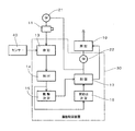
以下、本発明を図面に基づいて詳細に説明する。図1及び図2は本発明に係る自動追尾照射装置の好ましい実施形態を示す。図において、自動追尾照射装置には感熱センサー40が設けられ、感熱センサー40は害獣の侵入を忌避する領域(所定の領域)に侵入した害獣(被検知体)の体温を検知して害獣の侵入を判定する一方、感熱センサー40の信号は駆動制御装置30に入力されるようになっている。
Hereinafter, the present invention will be described in detail with reference to the drawings. 1 and 2 show preferred embodiments of the automatic tracking irradiation device according to the present invention. In the figure, the automatic tracking irradiation device is provided with a heat-
駆動制御装置30では感熱センサー40の検知信号が入力されるとCPUが起動され、CPUの機能手段である侵入検知手段13がサーモセンサー40の信号から所定の領域に害獣が侵入したことを検知する一方、サーモカメラ(撮像装置)11を作動させる。サーモカメラ30は対象を撮像し、サーモカメラ30の信号は駆動制御装置30に与えられるようになっている。なお、通常画像とサーモ画像とを切り替えて撮像し、サーモ画像を用いて演算処理を行うようにしてもよい。
In the
駆動制御装置30ではサーモカメラ11の信号が入力されると、CPUの機能手段である動態抽出手段14が撮像画像を得て画像パターンを抽出し、画像パターンの解析処理を行って害獣の種類を決定するとともに、画像パターンの変化から画像の動態部分を抽出するようになっている。
When the signal of the
画像動態部分が抽出されると、CPUの機能手段である動態決定手段15が害獣の動態部分の変化から害獣の動きを決定するとともに、CPUの機能手段である照射点決定手段16が画像パターンからレーザー光を照射する照射点を決定するようになっている。 When the image dynamic part is extracted, the dynamic determination means 15 which is a functional means of the CPU determines the movement of the pest from the change of the dynamic part of the pest, and the irradiation point determining means 16 which is the functional means of the CPU determines the image. The irradiation point to irradiate the laser beam is determined from the pattern.
動態決定手段15及び照射点決定手段16の信号はCPUの機能手段である制御手段17に与えられ、制御手段17はサーモカメラ11及びレーザー装置(光照射装置)10のステップモーター21、22に駆動制御信号を与え、サーモカメラ11及びレーザー装置(光照射装置)10を旋回又は揺動させて追尾動作をさせ、レーザー装置10はレーザー光を動く害獣の目に向けて照射し、サーモカメラ11は害獣の動きに追尾しながら撮像を行うようになっている。
The signals of the dynamic determination means 15 and the irradiation point determination means 16 are given to the control means 17 which is a functional means of the CPU, and the control means 17 is driven by the
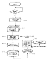
次に、制御処理について説明する。電源がONされると、駆動制御装置30では制御処理が開始され、感熱センサー40で害獣の体温が感知され、害獣が領域内に侵入したと判定されると、サーモカメラ11が作動されて害獣の姿が撮像されるとともに(ステップS10)、画像システム(CPU)が起動される(ステップS11)。
Next, the control process will be described. When the power is turned on, the
画像システムが起動されると、サーモカメラ11の撮像画像が取り込まれ、画像パターンの解析処理が行われ(ステップS12)、撮像画像の二値化処理などによって画像パターンが作成され、画像パターンから害獣の種類が決定されるとともに、画像パターンの動態部分のみが抽出されて画像パターンの処理する領域が限定され(ステップS13)、映像マトリックスの分割アドレス処理(番地設定)が行われ(ステップS14、図2の20参照)、マトリックスのアドレス指定が行われてステップモーター21、22の角度が設定され(ステップS15、S16)、サーモカメラ11及びレーザー装置10が指定されたアドレスに追尾動作されるとともに、レーザー装置10から害獣の目に向けて所定の強さのレーザー光が照射される。
When the image system is started, the captured image of the
ここで、映像マトリックスの分割アドレス処理について詳細に説明すると、映像の画像画面を縦横に分割してマトリックス座標を形成し、映像信号の走査線(V/H)に対して順に番地(番号)を割り当てる。番地数(分割数)の割当てはカメラの走査数や視野幅によって適正値にマッチングを行う。 Here, the division address processing of the video matrix will be described in detail. The image screen of the video is divided vertically and horizontally to form matrix coordinates, and the addresses (numbers) are sequentially assigned to the scanning lines (V / H) of the video signal. assign. The number of addresses (number of divisions) is assigned to an appropriate value according to the number of scans of the camera and the field of view.
次に、ターゲットの動画部の番地をロギングする。面積として、複数の番地が存在することが重要である。面積部分のセンターポイントを演算処理にて算出して番地を決定し、ステップモーター22を作動させてレーザー光の照射ポイントを決定した番地(座標位置)に移動させる。
Next, the address of the target video part is logged. It is important that there are multiple addresses as the area. The center point of the area portion is calculated by arithmetic processing to determine the address, and the
次回の移動時は軌跡移動(左右限定処理など‥‥)として演算処理を効率的に行うことができる。最短時間で演算処理してステップモーター22のモーター制御を行う。これにより、消費電力を軽減化でき、又ハードウェア処理速度のパフォーマンスを抑えることが可能となり、トータル的なコストダウンに繋がる。
At the time of the next movement, the arithmetic processing can be efficiently performed as the locus movement (left-right limited processing, etc.). The motor of the
以上のように、本例によれば、動く害獣に対してレーザー光を確実に照射させることができ、確実に害獣を忌避でき、又数少ない設備で広い領域をカバーできる。 As described above, according to this example, the moving vermin can be reliably irradiated with the laser beam, the vermin can be reliably repelled, and a wide area can be covered with a few facilities.
また、害獣の画像パターンのうち、動態部分を抽出して処理を行うようにしたので、高い演算処理能力を発揮する。 In addition, since the dynamic part of the image pattern of the vermin is extracted and processed, high computing power is exhibited.
10 レーザー装置
11 サーモカメラ
13 侵入検知手段
14 動態抽出手段
15 動態決定手段
16 照射点決定手段
17 制御手段
20、21 ステップモーター(追尾駆動装置)
30 駆動制御装置
40 感熱センサー
10
30
Claims (1)
レーザー光又はLED光を照射する光照射装置(10)と、
所定の領域を撮像する撮像装置(11)と、
該撮像装置(11)及び上記光照射装置(10)に追尾動作をさせる追尾駆動装置(21、22)と、
上記センサー(40)の信号から上記所定の領域に被検知体が侵入したことを検知する侵入検知手段(13)、該侵入検知手段(13)の信号を受け、上記撮像装置(11)の信号から被検知体の撮像画像を得るとともに、該撮像画像の変化から上記撮像画像の動態部分を抽出する動態抽出手段(14)、該動態抽出手段(14)の信号を受け、レーザー光又はLED光の照射点を決定する照射点決定手段(16)、上記動態抽出手段(14)の信号を受けて上記被検知体の動きを決定する動態決定手段(15)及び上記照射点決定手段(16)の信号を受け、上記光照射装置(10)からレーザー光又はLED光を被検知体に対して照射させるとともに、上記動態決定手段(15)の信号を受け、上記追尾駆動装置(21、22)を駆動させて上記被検知体の動きに対して上記撮像装置(11)及び光照射装置(10)に追尾動作をさせる制御手段(17)から構成される駆動制御装置(30)と、
を備えたことを特徴とする自動追尾照射装置。
A sensor (40) that detects the intrusion of the object to be detected into a predetermined area, and
A light irradiator (10) that irradiates laser light or LED light,
An imaging device (11) that captures a predetermined area and
The tracking drive device (21, 22) that causes the image pickup device (11) and the light irradiation device (10) to perform a tracking operation, and
The signal of the intrusion detection means (13) for detecting that the object to be detected has invaded the predetermined area from the signal of the sensor (40), the signal of the intrusion detection means (13), and the signal of the image pickup device (11). A laser light or an LED light is received from the signals of the dynamic extraction means (14) and the dynamic extraction means (14) that extract the dynamic portion of the captured image from the change of the captured image while obtaining the captured image of the object to be detected. The irradiation point determining means (16) for determining the irradiation point, the dynamics determining means (15) for determining the movement of the object to be detected in response to the signal of the dynamic extraction means (14), and the irradiation point determining means (16). In response to the signal of the above-mentioned light irradiating device (10), the object to be detected is irradiated with laser light or LED light, and the above-mentioned tracking driving device (21, 22) receives the signal of the above-mentioned dynamic determination means (15). A drive control device (30) composed of a control means (17) that drives the image pickup device (11) and the light irradiation device (10) to track the movement of the object to be detected.
An automatic tracking irradiation device characterized by being equipped with.
Priority Applications (1)
| Application Number | Priority Date | Filing Date | Title |
|---|---|---|---|
| JP2019089503A JP2020184887A (en) | 2019-05-10 | 2019-05-10 | Automatic tracking irradiation device |
Applications Claiming Priority (1)
| Application Number | Priority Date | Filing Date | Title |
|---|---|---|---|
| JP2019089503A JP2020184887A (en) | 2019-05-10 | 2019-05-10 | Automatic tracking irradiation device |
Publications (1)
| Publication Number | Publication Date |
|---|---|
| JP2020184887A true JP2020184887A (en) | 2020-11-19 |
Family
ID=73220557
Family Applications (1)
| Application Number | Title | Priority Date | Filing Date |
|---|---|---|---|
| JP2019089503A Pending JP2020184887A (en) | 2019-05-10 | 2019-05-10 | Automatic tracking irradiation device |
Country Status (1)
| Country | Link |
|---|---|
| JP (1) | JP2020184887A (en) |
Cited By (1)
| Publication number | Priority date | Publication date | Assignee | Title |
|---|---|---|---|---|
| JP2022143594A (en) * | 2021-03-18 | 2022-10-03 | Necプラットフォームズ株式会社 | Bird protection device, bird protection system, bird protection method and bird protection program |
-
2019
- 2019-05-10 JP JP2019089503A patent/JP2020184887A/en active Pending
Cited By (2)
| Publication number | Priority date | Publication date | Assignee | Title |
|---|---|---|---|---|
| JP2022143594A (en) * | 2021-03-18 | 2022-10-03 | Necプラットフォームズ株式会社 | Bird protection device, bird protection system, bird protection method and bird protection program |
| JP7171799B2 (en) | 2021-03-18 | 2022-11-15 | Necプラットフォームズ株式会社 | Bird-proof devices, bird-proof systems, bird-proof methods, and bird-proof programs |
Similar Documents
| Publication | Publication Date | Title |
|---|---|---|
| JP3919825B2 (en) | Apparatus and method for recognizing and determining the position of an animal part | |
| US7504956B2 (en) | System and method for pest detection | |
| US9381646B1 (en) | Insect and other small object image recognition and instant active response with enhanced application and utility | |
| US10853698B2 (en) | System and method of using multi-frame image features for object detection | |
| US20200323193A1 (en) | Automatic Animal Detection and Deterrent System | |
| KR20150130803A (en) | The method for monitoring communicable disease and system using the method, recording medium for performing the method | |
| ATE471696T1 (en) | EXPOSURE CONTROL WHEN DETECTING IONIZING RADIATION BASED ON SCANNING | |
| KR20210035252A (en) | Systems and methods for locating and removing insects | |
| GB2610734A (en) | Barcode readers with 3D camera(s) | |
| CN110378216B (en) | Target detection method, target detection device, image pickup apparatus, and storage medium | |
| JP2011138310A (en) | Method of determining number and perching position of harmful bird and apparatus therefor, and method of expelling harmful bird | |
| KR20190059107A (en) | System for detecting wasp | |
| JP2020184887A (en) | Automatic tracking irradiation device | |
| CN111724557A (en) | Electric power operation border crossing early warning system and method | |
| JP6059957B2 (en) | Wildlife identification device, wildlife identification method, and program | |
| CN213246585U (en) | Biological driving device | |
| JP2007037437A (en) | Rat extermination system | |
| JP7459959B2 (en) | Living body detection device, control method, and program | |
| Arowolo et al. | A Real Time Image Processing Bird Repellent System Using Raspberry Pi | |
| JP2018159640A (en) | System and method for monitoring tunnel face surface | |
| CA3099858A1 (en) | A railway weed control vehicle | |
| Ram et al. | A self induced warning system for wild animal trespassing using machine vision system | |
| KR102579085B1 (en) | Method and appratus for caturing of semiaquatic animals | |
| KR102018631B1 (en) | Device for target treatment of line-scan type using laser and control method for the same | |
| JP2020005532A (en) | Animal repulsion system, animal repulsion device and animal repulsion method |