JP2020157402A - Robot control device, robot control method, and robot system - Google Patents
Robot control device, robot control method, and robot system Download PDFInfo
- Publication number
- JP2020157402A JP2020157402A JP2019057543A JP2019057543A JP2020157402A JP 2020157402 A JP2020157402 A JP 2020157402A JP 2019057543 A JP2019057543 A JP 2019057543A JP 2019057543 A JP2019057543 A JP 2019057543A JP 2020157402 A JP2020157402 A JP 2020157402A
- Authority
- JP
- Japan
- Prior art keywords
- range
- control signal
- control
- frequency
- robot
- Prior art date
- Legal status (The legal status is an assumption and is not a legal conclusion. Google has not performed a legal analysis and makes no representation as to the accuracy of the status listed.)
- Pending
Links
- 238000000034 method Methods 0.000 title claims description 55
- 230000009467 reduction Effects 0.000 claims abstract description 59
- 230000007274 generation of a signal involved in cell-cell signaling Effects 0.000 claims abstract description 35
- 238000003860 storage Methods 0.000 claims abstract description 6
- 230000008859 change Effects 0.000 claims description 39
- 230000008569 process Effects 0.000 claims description 10
- 238000012545 processing Methods 0.000 abstract description 69
- 239000012636 effector Substances 0.000 description 25
- 230000036544 posture Effects 0.000 description 22
- 238000011946 reduction process Methods 0.000 description 17
- 238000010586 diagram Methods 0.000 description 11
- 230000000694 effects Effects 0.000 description 9
- 230000006870 function Effects 0.000 description 9
- 238000005452 bending Methods 0.000 description 7
- 230000001133 acceleration Effects 0.000 description 6
- 238000005259 measurement Methods 0.000 description 6
- WBMKMLWMIQUJDP-STHHAXOLSA-N (4R,4aS,7aR,12bS)-4a,9-dihydroxy-3-prop-2-ynyl-2,4,5,6,7a,13-hexahydro-1H-4,12-methanobenzofuro[3,2-e]isoquinolin-7-one hydrochloride Chemical compound Cl.Oc1ccc2C[C@H]3N(CC#C)CC[C@@]45[C@@H](Oc1c24)C(=O)CC[C@@]35O WBMKMLWMIQUJDP-STHHAXOLSA-N 0.000 description 5
- 238000004519 manufacturing process Methods 0.000 description 5
- 230000015654 memory Effects 0.000 description 5
- 230000000903 blocking effect Effects 0.000 description 4
- 238000004590 computer program Methods 0.000 description 4
- 238000012937 correction Methods 0.000 description 4
- 239000008186 active pharmaceutical agent Substances 0.000 description 3
- 230000007423 decrease Effects 0.000 description 2
- 238000013461 design Methods 0.000 description 2
- 239000004973 liquid crystal related substance Substances 0.000 description 2
- NJPPVKZQTLUDBO-UHFFFAOYSA-N novaluron Chemical compound C1=C(Cl)C(OC(F)(F)C(OC(F)(F)F)F)=CC=C1NC(=O)NC(=O)C1=C(F)C=CC=C1F NJPPVKZQTLUDBO-UHFFFAOYSA-N 0.000 description 2
- 230000000052 comparative effect Effects 0.000 description 1
- 238000005516 engineering process Methods 0.000 description 1
- 238000001914 filtration Methods 0.000 description 1
- 230000004044 response Effects 0.000 description 1
- 230000004043 responsiveness Effects 0.000 description 1
Images


Classifications
-
- B—PERFORMING OPERATIONS; TRANSPORTING
- B25—HAND TOOLS; PORTABLE POWER-DRIVEN TOOLS; MANIPULATORS
- B25J—MANIPULATORS; CHAMBERS PROVIDED WITH MANIPULATION DEVICES
- B25J9/00—Programme-controlled manipulators
- B25J9/16—Programme controls
- B25J9/1628—Programme controls characterised by the control loop
-
- B—PERFORMING OPERATIONS; TRANSPORTING
- B25—HAND TOOLS; PORTABLE POWER-DRIVEN TOOLS; MANIPULATORS
- B25J—MANIPULATORS; CHAMBERS PROVIDED WITH MANIPULATION DEVICES
- B25J9/00—Programme-controlled manipulators
- B25J9/0081—Programme-controlled manipulators with master teach-in means
-
- B—PERFORMING OPERATIONS; TRANSPORTING
- B25—HAND TOOLS; PORTABLE POWER-DRIVEN TOOLS; MANIPULATORS
- B25J—MANIPULATORS; CHAMBERS PROVIDED WITH MANIPULATION DEVICES
- B25J13/00—Controls for manipulators
- B25J13/08—Controls for manipulators by means of sensing devices, e.g. viewing or touching devices
- B25J13/085—Force or torque sensors
-
- B—PERFORMING OPERATIONS; TRANSPORTING
- B25—HAND TOOLS; PORTABLE POWER-DRIVEN TOOLS; MANIPULATORS
- B25J—MANIPULATORS; CHAMBERS PROVIDED WITH MANIPULATION DEVICES
- B25J13/00—Controls for manipulators
- B25J13/08—Controls for manipulators by means of sensing devices, e.g. viewing or touching devices
- B25J13/088—Controls for manipulators by means of sensing devices, e.g. viewing or touching devices with position, velocity or acceleration sensors
-
- B—PERFORMING OPERATIONS; TRANSPORTING
- B25—HAND TOOLS; PORTABLE POWER-DRIVEN TOOLS; MANIPULATORS
- B25J—MANIPULATORS; CHAMBERS PROVIDED WITH MANIPULATION DEVICES
- B25J9/00—Programme-controlled manipulators
- B25J9/10—Programme-controlled manipulators characterised by positioning means for manipulator elements
- B25J9/12—Programme-controlled manipulators characterised by positioning means for manipulator elements electric
-
- B—PERFORMING OPERATIONS; TRANSPORTING
- B25—HAND TOOLS; PORTABLE POWER-DRIVEN TOOLS; MANIPULATORS
- B25J—MANIPULATORS; CHAMBERS PROVIDED WITH MANIPULATION DEVICES
- B25J9/00—Programme-controlled manipulators
- B25J9/16—Programme controls
- B25J9/1602—Programme controls characterised by the control system, structure, architecture
-
- B—PERFORMING OPERATIONS; TRANSPORTING
- B25—HAND TOOLS; PORTABLE POWER-DRIVEN TOOLS; MANIPULATORS
- B25J—MANIPULATORS; CHAMBERS PROVIDED WITH MANIPULATION DEVICES
- B25J9/00—Programme-controlled manipulators
- B25J9/16—Programme controls
- B25J9/1679—Programme controls characterised by the tasks executed
-
- G—PHYSICS
- G05—CONTROLLING; REGULATING
- G05B—CONTROL OR REGULATING SYSTEMS IN GENERAL; FUNCTIONAL ELEMENTS OF SUCH SYSTEMS; MONITORING OR TESTING ARRANGEMENTS FOR SUCH SYSTEMS OR ELEMENTS
- G05B2219/00—Program-control systems
- G05B2219/30—Nc systems
- G05B2219/39—Robotics, robotics to robotics hand
- G05B2219/39195—Control, avoid oscillation, vibration due to low rigidity
-
- G—PHYSICS
- G05—CONTROLLING; REGULATING
- G05B—CONTROL OR REGULATING SYSTEMS IN GENERAL; FUNCTIONAL ELEMENTS OF SUCH SYSTEMS; MONITORING OR TESTING ARRANGEMENTS FOR SUCH SYSTEMS OR ELEMENTS
- G05B2219/00—Program-control systems
- G05B2219/30—Nc systems
- G05B2219/41—Servomotor, servo controller till figures
- G05B2219/41166—Adaptive filter frequency as function of oscillation, rigidity, inertia load
Abstract
Description
本開示は、ロボットにおいて振動を低減する技術に関する。 The present disclosure relates to a technique for reducing vibration in a robot.
従来、ロボットの技術分野において、エンドエフェクターに保持されたワークピースの振動を低減するための、以下のような技術が存在する。特許文献1の技術においては、あらかじめ、エンドエフェクターでワークピースを保持した状態におけるロボットが共振する振動数を特定する。そして、ロボットのサーボモーターを駆動制御する電流制御部に与えられるトルク制御信号(時間の関数として把握できる)に、帯域阻止フィルターを適用し、その振動数の成分をトルク制御信号から除去する。その結果、その振動数の成分を含まないトルク制御信号が電流制御部に与えられる。そのトルク制御信号に基づいて電流制御部によって駆動制御されたサーボモーターは、エンドエフェクターに保持されたワークピースをその振動数で共振させてしまうことがない。
Conventionally, in the technical field of robots, there are the following technologies for reducing the vibration of the workpiece held by the end effector. In the technique of
ロボットにおける共振周波数は、ロボットの制御点の位置によって異なる。このため、ある動作について、ロボットの振動の測定を行って共振周波数を特定し、トルク制御信号に帯域阻止フィルターを適用して振動を低減することができても、別の動作をロボットに実行させる場合には、そのままの設定では、十分な振動の低減を行うことができない。このため、新たな動作を行わせる場合には、その動作についてロボットの振動の測定を行って、帯域阻止フィルターの設定をし直し、トルク制御信号に帯域阻止フィルターを適用し直す必要がある。ロボットに新たな動作を教示するたびにこのような処理を行うことは、ユーザーに取って煩雑である。 The resonance frequency in the robot depends on the position of the control point of the robot. Therefore, for a certain operation, even if the vibration of the robot can be measured to identify the resonance frequency and the band blocking filter can be applied to the torque control signal to reduce the vibration, the robot is made to perform another operation. In that case, it is not possible to sufficiently reduce the vibration with the setting as it is. Therefore, when a new operation is to be performed, it is necessary to measure the vibration of the robot for the operation, reset the band blocking filter, and reapply the band blocking filter to the torque control signal. It is complicated for the user to perform such a process every time the robot is instructed to perform a new operation.
本開示の一形態によれば、ロボットを制御するための制御装置が提供される。この制御装置は、ロボットの可動部を移動させる動作を行うための第1制御信号から、あらかじめ定められた周波数の成分を低減して第2制御信号を生成することができる第2制御信号生成部と、前記ロボットの制御点の位置の範囲と周波数との組み合わせの情報を含む参照情報を記憶している記憶部と、を備え、前記第2制御信号生成部は、前記動作における前記ロボットの制御点の位置に基づいて、前記参照情報を参照して、前記第1制御信号から低減すべき周波数の成分を決定する。 According to one embodiment of the present disclosure, a control device for controlling a robot is provided. This control device is a second control signal generation unit capable of generating a second control signal by reducing a predetermined frequency component from the first control signal for performing an operation of moving a movable part of the robot. A storage unit that stores reference information including information on a combination of a range of positions of control points of the robot and a frequency is provided, and the second control signal generation unit controls the robot in the operation. Based on the position of the point, the reference information is referred to to determine the frequency component to be reduced from the first control signal.
A.第1実施形態:
A1.ロボットシステムの構成:
図1は、本実施形態のロボットシステムを示す説明図である。本実施形態のロボットシステムは、ロボット100と、エンドエフェクター200と、ロボット制御装置300と、教示装置600と、を備える。
A. First Embodiment:
A1. Robot system configuration:
FIG. 1 is an explanatory diagram showing a robot system of the present embodiment. The robot system of this embodiment includes a
ロボット100は、6個の回転関節X11〜X16を備えたアーム110を有する6軸ロボットである。アーム110は、基台180に支持されている。関節X11,X14,X16は、ねじり関節である。関節X12,X13,X15は、曲げ関節である。ロボット100は、6個の関節X11〜X16をそれぞれサーボモーターで回転させることにより、アーム110の先端170に取りつけられたエンドエフェクター200を、3次元空間中の指定された位置に指定された姿勢で配することができる。エンドエフェクター200が取りつけられるアーム110の先端170は、アーム110の両端のうち、基台180と接続されている端とは逆の端である。
The
3次元空間におけるエンドエフェクター200の位置を代表する地点を、TCP(Tool Center Point)とも呼ぶ。本実施形態においては、制御点としてのTCPは、ロボット100のアーム110の先端170にある。
A point representing the position of the
図1において、基台180の位置を基準として、ロボット100が設置された空間を規定する座標系をロボット座標系を示す。ロボット座標系は、水平面上において互いに直交するX軸およびY軸と、鉛直上向きを正方向とするZ軸とによって規定される三次元直交座標系である。本明細書において、単に「X軸」と表記した場合、ロボット座標系におけるX軸を表す。単に「Y軸」と表記した場合、ロボット座標系におけるY軸を表す。単に「Z軸」と表記した場合、ロボット座標系におけるZ軸を表す。ロボット座標系における任意の位置は、X軸方向の位置と、Y軸方向の位置と、Z軸方向の位置とにより特定できる。
In FIG. 1, the robot coordinate system is shown as a coordinate system that defines a space in which the
ロボット100のアーム110の先端170は、フランジ状すなわち円板状の形状で構成されている。ロボット100は、アーム110の先端170に力覚センサー190を備えている。エンドエフェクター200は、力覚センサー190を介して、ロボット100のアーム110の先端170に取りつけられている。力覚センサー190は、エンドエフェクター200に作用するX軸、Y軸、Z軸の3軸方向の力と、X軸、Y軸、Z軸まわりのトルクを測定することができる。力覚センサー190の出力は、ロボット制御装置300に送信され、ロボット100の制御に使用される。
The
エンドエフェクター200は、アーム110の先端に取りつけられている。エンドエフェクター200は、ロボット制御装置300に制御されて、ワークピースW01をつかむことができ、また、つかんでいるワークピースW01を離すことができる。その結果、たとえば、ロボット100とエンドエフェクター200とは、ロボット制御装置300に制御されて、ワークピースW01をつかんで移動させることができる。ワークピースW01は、具体的には、ロボット100が作業を行う対象物である。
The
ロボット制御装置300は、ロボット100に接続されており、ロボット100の動作を制御する。より具体的には、ロボット制御装置300は、ロボット100の関節X11〜X16を動かすサーボモーター410を駆動する。ロボット制御装置300は、プロセッサーであるCPU(Central Processing Unit)301、RAM(Random Access Memory)302、ROM(Read-Only Memory)303を備える。ロボット制御装置300には、ロボット100を制御するための制御プログラムがインストールされている。ロボット制御装置300においては、ハードウェア資源としてのCPU301、RAM302、ROM303と、制御プログラムとが協働する。具体的には、CPU301が、ROM303に記憶されたコンピュータープログラムをRAM302にロードして実行することによって、様々な機能を実現する。
The
教示装置600は、ロボット制御装置300に目標位置Stと目標力fStとを教示するための装置である。目標力fStは、成分として、直線的に作用する力と、トルクと、を含みうる。教示装置600は、いわゆる「ティーチングペンダント」である。ロボット100に作業を実行させる際には、あらかじめ、教示装置600によるロボットの動作の教示が行われる。ロボット制御装置300は、教示の結果をデータとしてRAM302に格納する。ロボット制御装置300は、ロボット100に作業を実行させる段階において、RAM302に格納された教示結果を表すデータに基づいて、ロボット100を制御する。
The
教示装置600は、プロセッサーであるCPU601、RAM602、ROM603を備える。教示装置600には、ロボット制御装置300に目標位置Stと目標力fStとを教示するための制御プログラムがインストールされている。教示装置600においては、ハードウェア資源としてのCPU601、RAM602、ROM603と、制御プログラムとが協働する。具体的には、CPU601が、ROM603に記憶されたコンピュータープログラムをRAM602にロードして実行することによって、様々な機能を実現する。
The
教示装置600は、さらに、入力装置604と、出力装置605を備える。入力装置604は、ユーザーからの指示を受け付ける。入力装置604は、例えば、キーボード604a、操作レバー604b、タッチパネル604c等である。出力装置605は、ユーザーに、ロボット100の動作設定のためのユーザーインターフェイスや警告を含む各種の情報を出力する。出力装置605は、例えば、液晶ディスプレイやスピーカー等である。本実施形態においては、出力装置605としての液晶ディスプレイの上に、入力装置604としてのタッチパネル604cが設けられている。
The
図2は、ロボット制御装置300の構成要素と、ロボット100が備えるサーボモーター410、位置センサー420および力覚センサー190と、の関係を示すブロック図である。ロボット制御装置300は、その機能部として、制御信号生成部310と、位置制御部320と、速度制御部330と、フィルター処理部340と、トルク制御部350と、サーボアンプ360と、フィルター設定部345と、力制御部390と、を備える。制御信号生成部310と、位置制御部320と、速度制御部330と、フィルター処理部340と、フィルター設定部345と、トルク制御部350と、力制御部390とは、CPU301によって実現される。
FIG. 2 is a block diagram showing the relationship between the components of the
制御信号生成部310は、エンドエフェクター200が位置すべき目標位置Stを表す位置制御信号を生成し、位置制御部320に出力する。制御信号生成部310は、力制御を実施すべき指示をユーザーから受けている場合には、目標力fSt、すなわち、エンドエフェクター200が発生させるべき力およびその力の方向、ならびにトルクおよびそのトルクの向きを表す力制御信号を生成し、力制御部390に出力する。制御信号生成部310は、ロボット100が実行中の動作を表すコマンドを、フィルター設定部345に出力する。
The control
力制御部390は、目標力fSt、すなわち、エンドエフェクター200が発生させるべき力およびその力の方向、ならびにトルクおよびそのトルクの向きを表す力制御信号を、制御信号生成部310から受信する。力制御部390は、エンドエフェクター200に作用しているX軸、Y軸、Z軸の3軸方向の力と、U軸、V軸、W軸まわりのトルクとを、力覚センサー190から受信する。エンドエフェクター200に作用しているX軸、Y軸、Z軸の3軸方向の力と、U軸、V軸、W軸まわりのトルクとを、図2において、まとめてfSと表記する。U軸方向は、X軸方向を中心軸とする回転方向である。V軸方向は、Y軸方向を中心軸とする回転方向である。W軸方向は、Z軸方向を中心軸とする回転方向である。力制御部390は、ロボット100の位置センサー420から、各サーボモーター410の回転位置を受信する。そして、力制御部390は、それらのパラメーターに基づいて、位置の補正量ΔSを決定し、補正量ΔSを表す信号を位置制御部320に出力する。
The
位置制御部320は、制御信号生成部310から、目標位置Stを表す位置制御信号を受信する。位置制御部320は、力制御部390から、位置の補正量ΔSをあらわす信号を受信する。位置制御部320は、位置フィードバックとして、ロボット100の位置センサー420から、各サーボモーター410の回転位置を受信する。位置制御部320は、それらの情報に基づいて、ロボット100の各サーボモーター410の速度制御信号を生成し、速度制御部330とフィルター設定部345に、出力する。
The
なお、位置制御部320は、力制御を実施すべき指示を制御信号生成部310から受けていない場合には、速度制御信号の生成に際して、力制御部390から受信した情報は考慮しない。
When the
速度制御部330は、位置制御部320から速度制御信号を受信する。また、速度制御部330は、速度フィードバックとして、ロボット100の位置センサー420から、各サーボモーター410の回転速度を受信する。速度制御部330は、その速度制御信号と、各サーボモーター410の回転速度と、に基づいて、トルク制御信号を生成し、フィルター処理部340に出力する。
The
フィルター設定部345は、制御信号生成部310から実行中の動作を表すコマンドを受信する。フィルター設定部345は、受信したコマンドに応じて、参照情報を参照し、トルク制御信号から除去すべき1以上の周波数成分を指示する制御信号を生成し、フィルター処理部340に出力する。フィルター設定部345は、トルク制御信号から除去すべき周波数成分は存在しない旨の制御信号を、フィルター処理部340に出力することもできる。
The
フィルター処理部340は、速度制御部330から、トルク制御信号を受信する。また、フィルター処理部340は、フィルター設定部345から、除去すべき1以上の周波数成分の制御信号を受信する。フィルター処理部340は、速度制御部330が出力したトルク制御信号に対して、帯域除去フィルターを使用して、トルク制御信号に応じた1以上の周波数成分を除去する処理を行って、新たなトルク制御信号を生成し、出力する。より具体的には、フィルター処理部340により、特定の周波数成分が−30dB、低減される。
The
フィルター処理部340は、その特定の周波数を含むあらかじめ定められた幅の周波数範囲の成分を、制御信号から低減して、新たな制御信号を生成する。具体的には、その特定の周波数±Δfの範囲の周波数成分が、低減される。本実施形態においてΔfは1Hzである。
The
速度制御部330が出力したトルク制御信号も、フィルター処理部340が生成する新たなトルク制御信号も、いずれもアーム110およびエンドエフェクター200を移動させる動作を行うための制御信号である。速度制御部330が出力したトルク制御信号を、「第1制御信号CS1」と呼ぶ。フィルター処理部340が生成する新たなトルク制御信号を、「第2制御信号CS2」と呼ぶ。
Both the torque control signal output by the
フィルター処理部340において除去される周波数成分は、実行中の動作を表すコマンドに応じてあらかじめ定められた周波数の成分である。実行中の動作を表すコマンドに応じてあらかじめ定められた周波数は、たとえば、(i)その動作の終了時点のロボット100の姿勢におけるロボット100の振動の振動数、(ii)その動作の開始時点のロボット100の姿勢におけるロボット100の振動の振動数、(iii)その動作のうち速度が変更される地点に制御点があるときのロボット100の姿勢におけるロボット100の振動の振動数である。
The frequency component removed by the
本明細書において、トルク制御信号などの制御信号において所定の周波数成分を低減することにより、その周波数による制御対象物の共振を低減する処理を、「振動低減処理」と呼ぶ。また、制御信号において所定の周波数成分を低減することにより、その周波数による制御対象物の共振を低減する機能を、「振動低減機能」と呼ぶ。 In the present specification, a process of reducing a predetermined frequency component in a control signal such as a torque control signal to reduce resonance of a controlled object due to that frequency is referred to as a “vibration reduction process”. Further, a function of reducing the resonance of the controlled object due to the frequency by reducing a predetermined frequency component in the control signal is called a "vibration reduction function".
フィルター処理部340は、フィルター設定部345から、除去すべき周波数は存在しない旨の制御信号を受信した場合には、速度制御部330から受信したトルク制御信号を、そのまま出力する。このような処理を行うことにより、速度制御部330から受信したトルク制御信号に基づいて、本来の制御信号に忠実にロボットを駆動することができる。
When the
トルク制御部350は、フィルター処理部340から、トルク制御信号を受信する。また、トルク制御部350は、サーボアンプ360から、各サーボモーター410に供給する電流の電流量を表すフィードバック信号を受信する。トルク制御部350は、そのトルク制御信号と、各サーボモーター410の電流フィードバック信号と、に基づいて、ロボット100を駆動する駆動信号DSを生成する。より具体的には、トルク制御部350は、トルク制御信号と、各サーボモーター410の電流フィードバック信号と、に基づいて、各サーボモーター410に供給する電流量を決定し、サーボアンプ360を介して、各サーボモーター410を駆動する。
The
A2.振動低減機能の設定:
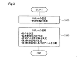
図3は、本実施形態のロボットシステム1の運用の流れを示すフローチャートである。本実施形態のロボットシステム1の運用においては、まずステップS100において、ロボットが製造される。その際、ロボット100の制御点TCPの位置の範囲と、振動低減処理において低減すべき周波数と、の1以上の組み合わせの情報を含む参照情報306が生成される。参照情報306は、RAM302に格納される(図1参照)。すなわち、参照情報306は、ステップS200のロボット100の運用に先だって、準備される。
A2. Vibration reduction function setting:
FIG. 3 is a flowchart showing an operation flow of the
ステップS200において、ロボット100の運用が行われ、製品の製造に使用される。より具体的には、ロボット100に作業を実行させるための動作が決定される。この処理は、教示装置600を介してユーザーからの指示を受けて、ロボット制御装置300が実行する。
In step S200, the
そして、ロボット制御装置300の制御信号生成部310(図2参照)が、各動作における目標位置を表す位置制御信号を生成する。ロボット制御装置300のフィルター設定部345が、各各動作におけるロボット100の制御点TCPの位置の情報に基づいて、参照情報306を参照して、第1制御信号CS1から低減すべき周波数の成分を決定する。周波数の成分の決定については、以下で、さらに説明する。
Then, the control signal generation unit 310 (see FIG. 2) of the
その後、ロボット制御装置300のフィルター処理部340が、速度制御部330から受け取った第1制御信号CS1に対して、周波数成分を除去する処理を行って、第2制御信号CS2を生成する(図2参照)。ロボット制御装置300のトルク制御部350は、フィルター処理部340から第2制御信号CS2を受け取って、第2制御信号CS2に基づいて、各サーボモーター410を駆動して、アーム110を移動させる。図3の処理によって、最終的にロボット100が制御される。このため、図3の処理は、広い意味で、ロボット100の制御方法として把握することもできる。
After that, the
図4は、振動低減処理において低減される周波数と対応づけられている、ロボット100の制御点TCPの位置の範囲を示す説明図である。図4においては、ロボット100の関節X12の回転軸が、ロボット座標系のY軸と平行になる姿勢でロボットが描かれている。関節X12は、ロボット100において基台180に最も近い曲げ関節である。図4において、ロボット100の関節X12は、ロボット座標系の原点Oに対して、X軸の負の方向にDxだけオフセットしており、Z軸の正の方向にDzだけオフセットしている。以下の説明では、関節X12の回転軸の位置であって、ロボット座標系のXZ平面と交わる点を、基準点O2と呼ぶ。なお、図4において、X軸方向の寸法とZ軸方向の寸法とは、1:1の比で描かれているわけではない。
FIG. 4 is an explanatory diagram showing a range of positions of the control point TCP of the
ロボット100に対して、基準点O2を基準として、3個の位置の範囲Ar0,Ar1,Ar2が定められている。振動低減処理において低減される周波数を決定する際に参照される参照情報306(図1参照)は、図4に示すロボットの制御点TCPの位置の範囲Ar0,Ar1,Ar2と周波数との組み合わせの情報を含む。
With respect to the
参照情報306は、以下の処理によって生成される(図3のS100参照)。まず、基準点O2に対して様々な位置に制御点TCPが配されて、そのときのロボット100の共振周波数が測定される。なお、測定は、アーム110の先端170に取りつけられた6軸の加速度センサーを使用して行われる。より具体的には、加速度センサーは、力覚センサー190の先に取りつけられる。それらの測定結果を、基準点O2に対する制御点TCPの各位置に、共振周波数f11〜f15,f21〜f29,f31〜f33として示す。なお、共振周波数f11〜f15,f21〜f29,f31〜f33は、その順に高い値を有する(f11<f37)。なお、大きさの順に並べたときに隣り合う共振周波数は、互いに等しい測定値を有する場合もある。
The reference information 306 is generated by the following processing (see S100 in FIG. 3). First, control point TCP is arranged at various positions with respect to the reference point O2, and the resonance frequency of the
図4より、おおまかには、基準点O2よりも下方で基台180を含む範囲において、共振周波数が高く(f31〜f33参照)、基準点O2から遠い位置の範囲において、共振周波数が低く(f11〜f15参照)、基準点O2に近い位置の範囲において、共振周波数が中程度である(f21〜f29参照)ことがわかる。このため、本実施形態の参照情報306においては、共振周波数は3個のグループに分けられ、それぞれ共振周波数が測定された各点が含まれる位置の範囲Ar0,Ar1,Ar2が対応づけられる。 From FIG. 4, roughly, the resonance frequency is high in the range below the reference point O2 including the base 180 (see f31 to f33), and the resonance frequency is low in the range far from the reference point O2 (f11). ~ F15), it can be seen that the resonance frequency is medium (see f21 to f29) in the range of the position close to the reference point O2. Therefore, in the reference information 306 of the present embodiment, the resonance frequencies are divided into three groups, and the range Ar0, Ar1, Ar2 of the position including each point where the resonance frequency is measured is associated with each group.
非低減範囲Ar0は、基準点O2を頂点とし、基準点O2からZ軸の負方向に伸びる基準線LSを中心線とし、ロボット座標系のXY平面を底面とする円錐形を有する。円錐の母線が基準線LSとなす角をθthとする。非低減範囲Ar0には、基台180が含まれる。
The non-reduction range Ar0 has a conical shape with the reference point O2 as the apex, the reference line LS extending from the reference point O2 in the negative direction of the Z axis as the center line, and the XY plane of the robot coordinate system as the bottom surface. Let θth be the angle formed by the generatrix of the cone with the reference line LS. The non-reduction range Ar0 includes the
第1範囲Ar1は、基準点O2を中心とする、あらかじめ定められた大きさの半径Rthの球状の空間から、非低減範囲Ar0を除いた空間である。なお、図4において、X軸方向の寸法とZ軸方向の寸法とは、1:1の比で描かれていないため、第1範囲Ar1の外縁の形状は、図4において、円ではなく楕円となっている。 The first range Ar1 is a space centered on the reference point O2, which is a spherical space having a predetermined size and a radius Rth, excluding the non-reduction range Ar0. Since the dimensions in the X-axis direction and the dimensions in the Z-axis direction are not drawn in a ratio of 1: 1 in FIG. 4, the shape of the outer edge of the first range Ar1 is not a circle but an ellipse in FIG. It has become.
第2範囲Ar2は、第1範囲Ar1を囲む空間である。第2範囲Ar2の外縁を規定する曲面は、アーム110の先端170の制御点TCPがとりうる位置の外縁である。第2範囲Ar2は、そのように定められる外縁で囲まれた空間から、非低減範囲Ar0および第1範囲Ar1を除いた空間である。
The second range Ar2 is a space surrounding the first range Ar1. The curved surface that defines the outer edge of the second range Ar2 is the outer edge of the position where the control point TCP of the
第1範囲Ar1に対して、第1範囲Ar1に対応づけられた共振周波数f11〜f15の最大値と最小値の中間の値[(f15−f11)/2]が、低減すべき周波数F11として割り当てられる。第2範囲Ar2に対応づけられた共振周波数f21〜f29の最大値と最小値の中間の値[(f29−f21)/2]が、低減すべき周波数F21として割り当てられる。非低減範囲Ar0に対しては、低減すべき周波数は、割り当てられない。 With respect to the first range Ar1, a value [(f15-f11) / 2] between the maximum value and the minimum value of the resonance frequencies f11 to f15 associated with the first range Ar1 is assigned as the frequency F11 to be reduced. Be done. An intermediate value [(f29-f21) / 2] between the maximum value and the minimum value of the resonance frequencies f21 to f29 associated with the second range Ar2 is assigned as the frequency F21 to be reduced. No frequency to be reduced is assigned to the non-reduction range Ar0.
共振周波数f11〜f15,f21〜f29の周波数の範囲は、それぞれグループにおける最大値と最小値の中間の値同士の間隔が(Δf×2)より大きくなるように、グループ分けされる。(Δf×2)は、フィルター処理部340(図2参照)が周波数成分を低減する際の処理対象の周波数成分の幅である。このようにして定められる共振周波数f11〜f15のグループに対応づけられる位置の範囲Ar1と、共振周波数f21〜f29のグループに対応づけられる位置の範囲Ar2とは、振動低減処理において低減される周波数の範囲が互いに重複しない。言い替えれば、低減すべき周波数と対応づけられる位置の範囲の区分は、振動低減処理において低減される周波数の範囲が互いに重複しないように、設定される。 The frequency ranges of the resonance frequencies f11 to f15 and f21 to f29 are grouped so that the interval between the intermediate values of the maximum value and the minimum value in the group is larger than (Δf × 2). (Δf × 2) is the width of the frequency component to be processed when the filter processing unit 340 (see FIG. 2) reduces the frequency component. The range Ar1 of the position corresponding to the group of the resonance frequencies f11 to f15 and the range Ar2 of the position corresponding to the group of the resonance frequencies f21 to f29 defined in this way are frequencies of frequencies reduced in the vibration reduction process. The ranges do not overlap each other. In other words, the division of the range of the position associated with the frequency to be reduced is set so that the range of the frequency to be reduced in the vibration reduction process does not overlap with each other.
参照情報306(図1参照)は、そのようにして定められる第1範囲Ar1と周波数F11との組み合わせの情報、および第2範囲Ar2と周波数F21との組み合わせの情報を、含む。参照情報306は、非低減範囲Ar0の情報も含む。非低減範囲Ar0は、周波数と対応づけられていない。 Reference information 306 (see FIG. 1) includes information on the combination of the first range Ar1 and the frequency F11 thus defined, and information on the combination of the second range Ar2 and the frequency F21. Reference information 306 also includes information on the non-reduction range Ar0. The non-reduction range Ar0 is not associated with frequency.
図5は、参照情報306が格納している制御点の位置の範囲と周波数との組み合わせの情報を示す表である。非低減範囲Ar0は、実質的には、制御点TCPと基準点O2とを結ぶ線分と基準線LSとがなす角θが、θthよりも小さい範囲、として規定することができる。そのような位置の範囲に対しては、低減すべき周波数は対応づけられない(図5の下段参照)。 FIG. 5 is a table showing information on the combination of the range of the position of the control point and the frequency stored in the reference information 306. The non-reduction range Ar0 can be defined as a range in which the angle θ formed by the line segment connecting the control point TCP and the reference point O2 and the reference line LS is smaller than θth. The frequency to be reduced cannot be associated with the range of such positions (see the lower part of FIG. 5).
第1範囲Ar1は、実質的には、制御点TCPと基準点O2との距離Rtcpが、Rthよりも小さい範囲であって、制御点TCPと基準点O2とを結ぶ線分と基準線LSとがなす角θが、θth以上である範囲、として規定することができる。そのような位置の範囲に対しては、低減すべき周波数として、F11が対応づけられる(図5の左上部照)。 The first range Ar1 is substantially a range in which the distance Rtcp between the control point TCP and the reference point O2 is smaller than Rth, and the line segment connecting the control point TCP and the reference point O2 and the reference line LS It can be defined as a range in which the angle θ formed by the two is equal to or greater than θth. F11 is associated with the range of such positions as the frequency to be reduced (see the upper left part of FIG. 5).
第2範囲Ar2は、実質的には、制御点TCPと基準点O2との距離Rtcpが、Rth以上の範囲であって、制御点TCPと基準点O2とを結ぶ線分と基準線LSとがなす角θが、θth以上である範囲、として規定することができる。そのような位置の範囲に対しては、低減すべき周波数として、F21が対応づけられる(図5の右上部照)。 In the second range Ar2, the distance Rtcp between the control point TCP and the reference point O2 is substantially in the range of Rth or more, and the line segment connecting the control point TCP and the reference point O2 and the reference line LS are It can be defined as a range in which the angle θ formed is θth or more. F21 is associated with the range of such positions as the frequency to be reduced (see the upper right part of FIG. 5).
本実施形態において、制御点TCPは、ロボット100のアーム110の先端170の位置にある。このため、エンドエフェクター200の情報を必要とせず、ロボット100の設計情報に基づいて参照情報306を生成して(図3のS100参照)、その参照情報306に基づいて有効にロボット100の振動を低減することができる(図3のS200参照)。
In this embodiment, the control point TCP is located at the
ロボット100を製造する段階(図3のS100参照)で参照情報306を生成しない態様においては、ロボット100の運用の段階(図3のS200参照)において、どの程度、有効な振動低減処理が実行されるか、特定することができない。このため、運用の段階における振動の発生を予防し、発生した振動の早期の収束を図るために、ロボット100のアーム110の移動速度の上限および加速度の上限、ならびにアーム110が支持する対象物の質量の大きさに応じて設定される加速度の制限を、低く設定する必要がある。また、アーム110のフィードバック制御において行われるPID制御の比例要素、積分要素、微分要素の各係数についても、振動が収束しやすいように、安定性が高い設定をしなければならなかった。これらの制限は、振動が最も発生しやすいアーム110の姿勢において、十分に振動を抑制できるように、行われる必要がある。その結果、ロボット100の運用段階において、ロボット100のアーム110の動きは遅くなり、動作のサイクルタイムが長くなっていた。
In the embodiment in which the reference information 306 is not generated at the stage of manufacturing the robot 100 (see S100 of FIG. 3), to what extent effective vibration reduction processing is executed at the stage of operating the robot 100 (see S200 of FIG. 3). Or cannot be identified. Therefore, in order to prevent the occurrence of vibration in the operation stage and to achieve the early convergence of the generated vibration, the upper limit of the moving speed and the upper limit of the acceleration of the
しかし、本実施形態においては、ロボットを製造する段階(図3のS100参照)で、ロボット100の製造者が参照情報306を生成できる。このため、ロボットの運用の段階(図3のS200参照)において、参照情報306を使用した有効な振動低減処理が実行されることが期待できる。よって、ロボット100の製造者は、ロボットを製造する段階(図3のS100参照)において、ロボット100のアーム110の移動速度の上限および加速度の上限、ならびにアーム110が支持する対象物の質量に応じた加速度の制限を、上記の比較例に比べて高く設定することができる。また、PID制御の比例要素、積分要素、微分要素の各係数についても、より応答性を重視した設定をすることができる。その結果、ロボット100の運用の段階において、アーム110に高速な移動を行わせることができ、その結果、動作のサイクルタイムを短くすることができる。
However, in the present embodiment, the manufacturer of the
図6は、図3のステップS200において、各動作に対して振動低減処理の内容が指定される際の教示装置600の表示を示す図である。図6の表示は、振動低減機能の設定装置として機能する教示装置600を使用して振動低減機能の設定が行われる際に、出力装置605としてのディスプレイに表示される。
FIG. 6 is a diagram showing a display of the
図6の表中の左端の列は、動作を区別するための番号である。図6の表中の中央の2列は、振動低減処理において低減される対象周波数を表すパラメーターParam1,Param2を示す。本実施形態においては、各番号に対応する動作に対して、最大2個の対象振動数が設定される。すなわち、第1制御信号CS1から、最大二つの周波数成分が除去される(図2の340参照)。 The leftmost column in the table of FIG. 6 is a number for distinguishing the operation. The two central columns in the table of FIG. 6 show the parameters Param1 and Param2 representing the target frequencies to be reduced in the vibration reduction process. In the present embodiment, a maximum of two target frequencies are set for the operation corresponding to each number. That is, a maximum of two frequency components are removed from the first control signal CS1 (see 340 in FIG. 2).
図6の表中の右端の欄は、「種類」の欄である。「種類」の欄は、振動の低減の態様を指定する入力インターフェイスである。「種類」の欄においては、「通常」、「両方」、「境界切替え」、および「変速点切替え」の4個の選択肢の中から一つが選択される。「種類」の欄による指定の内容については、後に説明する。「種類」の欄の指定に応じて、振動の低減の態様が決定され、一つまたは二つの対象振動数を表すパラメーターParam1,Param2として、F11,F21が指定される。F11,F21は、参照情報306(図1および図5参照)において、制御点の位置と対応づけられて、格納されている。 The rightmost column in the table of FIG. 6 is a “type” column. The "Type" column is an input interface that specifies the mode of vibration reduction. In the "type" column, one is selected from four options of "normal", "both", "boundary switching", and "shift point switching". The contents specified in the "Type" column will be described later. The mode of vibration reduction is determined according to the designation in the "type" column, and F11 and F21 are designated as the parameters Param1 and Param2 representing one or two target frequencies. F11 and F21 are stored in reference information 306 (see FIGS. 1 and 5) in association with the position of the control point.
たとえば、他の設定画面において、図6の表中の番号1に対して、動作Op10が割り当てられたものとする。動作Op10は、第1範囲Ar1内の位置P11から、第2範囲Ar2内の位置P12に、制御点が移動する動作である(図4の中段右部参照)。動作Op10において、第1範囲Ar1と第2範囲Ar2の境界に位置する制御点TCPの位置を、位置P13として示す。動作Op10においては、制御点TCPは、位置P13の前後を一定の速度で移動する。
For example, on another setting screen, it is assumed that the operation Op10 is assigned to the
「種類」の欄が「通常」に設定されている場合には、フィルター設定部345(図2参照)は、振動低減処理において低減すべき周波数として、動作の終点が属する位置の範囲に対応づけられた周波数を、決定する。その結果、図6の表中の番号1に対応づけられた動作Op10については、フィルター処理部340(図2参照)は、動作Op10を指示する第1制御信号CS1から、参照情報306において第2範囲Ar2と対応づけられている周波数F21の成分を低減して、第2制御信号CS2を生成する(図6の番号1欄のParam2参照)。図6の「種類」の欄は、デフォルトでは、「通常」に設定される。
When the "Type" column is set to "Normal", the filter setting unit 345 (see FIG. 2) associates the frequency to be reduced in the vibration reduction process with the range of the position to which the end point of the operation belongs. Determine the frequency. As a result, with respect to the operation Op10 associated with the
このような処理を行うことにより、第1制御信号CS1で指示される動作Op10が終了した後の残留振動を、効果的に低減できる、第2制御信号CS2を生成することができる。 By performing such processing, it is possible to generate the second control signal CS2 that can effectively reduce the residual vibration after the operation Op10 instructed by the first control signal CS1 is completed.
他の設定画面において、図6の表中の番号2に対して、動作Op10が割り当てられたものとする。なお、実際には、図6の各番号には異なる動作が対応づけられる。しかし、ここでは、技術の理解を容易にするため、図6の表中の番号2に対しても、動作Op10が割り当てられたものとする。以降で説明する番号3についても同様である。
On the other setting screen, it is assumed that the operation Op10 is assigned to the
「種類」の欄が「両方」に設定されている場合には、フィルター設定部345(図2参照)は、振動低減処理において低減すべき周波数として、動作の終点が属する位置の範囲に対応づけられた周波数と、動作の始点が属する位置の範囲に対応づけられた周波数とを、決定する。その結果、図6の表中の番号2に対応づけられた動作Op10については、フィルター処理部340(図2参照)は、動作Op10を指示する第1制御信号CS1から、参照情報306において第2範囲Ar2と対応づけられている周波数F21の成分と、第1範囲Ar1と対応づけられている周波数F11の成分と、を低減して、第2制御信号CS2を生成する(図6の番号2欄のParam1,Param2参照)。
When the "Type" column is set to "Both", the filter setting unit 345 (see FIG. 2) associates the frequency to be reduced in the vibration reduction process with the range of the position to which the end point of the operation belongs. The frequency and the frequency associated with the range of the position to which the start point of the operation belongs are determined. As a result, with respect to the operation Op10 associated with the
このような処理を行うことにより、制御点TCPが第2範囲Ar2を移動しているとき、および動作終了後の制御点TCPの振動を、抑制できることに加え、制御点TCPが第1範囲Ar1を移動しているときの制御点TCPの振動を、効果的に低減できる、第2制御信号CS2を生成することができる(図4のOp11参照)。 By performing such processing, in addition to being able to suppress the vibration of the control point TCP when the control point TCP is moving in the second range Ar2 and after the operation is completed, the control point TCP sets the first range Ar1. It is possible to generate a second control signal CS2 that can effectively reduce the vibration of the control point TCP when it is moving (see Op11 in FIG. 4).
他の設定画面において、図6の表中の番号3に対して、動作Op10が割り当てられたものとする。
On the other setting screen, it is assumed that the operation Op10 is assigned to the
「種類」の欄が「境界切替え」に設定されている場合には、フィルター設定部345(図2参照)は、振動低減処理において低減すべき周波数として、動作の終点が属する位置の範囲に対応づけられた周波数と、動作の始点が属する位置の範囲に対応づけられた周波数とを、決定する。そして、制御点TCPが第1範囲Ar1内を移動する第1部分動作Op11を指示する部分については、低減すべき周波数は、動作の始点P11が属する第1範囲Ar1に対応づけられた周波数F11とされる。制御点TCPが第2範囲Ar2内を移動する第2部分動作Op12を指示する部分については、低減すべき周波数は、動作の終点P12が属する第2範囲Ar2に対応づけられた周波数F21とされる。 When the "Type" column is set to "Boundary switching", the filter setting unit 345 (see FIG. 2) corresponds to the range of the position to which the end point of the operation belongs as the frequency to be reduced in the vibration reduction processing. The assigned frequency and the frequency associated with the range of the position to which the start point of the operation belongs are determined. Then, for the portion instructing the first partial operation Op11 in which the control point TCP moves in the first range Ar1, the frequency to be reduced is the frequency F11 associated with the first range Ar1 to which the start point P11 of the operation belongs. Will be done. For the part instructing the second part operation Op12 in which the control point TCP moves in the second range Ar2, the frequency to be reduced is the frequency F21 associated with the second range Ar2 to which the end point P12 of the operation belongs. ..
その結果、図6の表中の番号3に対応づけられた動作Op10については、フィルター処理部340(図2参照)は、動作Op10を指示する第1制御信号CS1から、第2制御信号CS2を生成する際に、以下の処理を行う。すなわち、フィルター処理部340は、第1制御信号CS1のうち、制御点TCPが第1範囲Ar1内を移動する第1部分動作Op11を指示する部分について、参照情報306において第1範囲Ar1と対応づけられている周波数F11の成分を低減する。そして、フィルター処理部340は、第1制御信号CS1のうち、制御点TCPが第2範囲Ar2内を移動する第2部分動作Op12を指示する部分について、参照情報306において第2範囲Ar2と対応づけられている周波数F21の成分を低減する。
As a result, with respect to the operation Op10 associated with the
このような処理を行うことにより、第1範囲Ar1と対応づけられている周波数F11の成分と第2範囲Ar2と対応づけられている周波数F21の成分との両方を、一貫して低減する態様(図6の表中の番号2欄参照)と比べて、以下のような効果が得られる。すなわち、位置ずれを少なくしつつ、第1制御信号CS1が指示する動作のうちの第1部分動作Op11について、振動を効果的に低減することができ、第2部分動作Op12についても、振動を効果的に低減することができる。
By performing such processing, both the component of the frequency F11 associated with the first range Ar1 and the component of the frequency F21 associated with the second range Ar2 are consistently reduced (a mode (). Compared with the
他の設定画面において、図6の表中の番号4に対して、動作Op20が割り当てられたものとする。動作Op20は、第1範囲Ar1内の位置P21から第2範囲Ar2内の位置P22に制御点TCPが移動する動作である(図4の上段右部参照)。ただし、動作Op20においては、第2範囲Ar2内のあらかじめ定められた変更点P23において、制御点TCPは速度を変えて移動する。なお、本明細書のフィルター設定部345およびフィルター処理部340の説明において、「速度」は、大きさと向きを含む概念である。すなわち、大きさが同じで向きが変わる変更も、速度の変更に含まれる。
On the other setting screen, it is assumed that the operation Op20 is assigned to the
「種類」の欄が「変更点切替え」に設定されている場合には、フィルター設定部345(図2参照)は、振動低減処理において低減すべき周波数として、動作の終点が属する位置の範囲に対応づけられた周波数と、動作の始点が属する位置の範囲に対応づけられた周波数とを、決定する。そして、制御点TCPが変更点に達する前の部分については、低減すべき周波数は、動作の始点が属する位置の範囲に対応づけられた周波数とされる。制御点TCPが変更点に達した後の部分については、低減すべき周波数は、動作の終点が属する位置の範囲に対応づけられた周波数とされる。 When the "Type" column is set to "Change point switching", the filter setting unit 345 (see FIG. 2) sets the frequency to be reduced in the vibration reduction process to the range of the position to which the end point of the operation belongs. The associated frequency and the frequency associated with the range of positions to which the start point of operation belongs are determined. Then, for the portion before the control point TCP reaches the change point, the frequency to be reduced is the frequency corresponding to the range of the position to which the start point of the operation belongs. For the portion after the control point TCP reaches the change point, the frequency to be reduced is the frequency corresponding to the range of the position to which the end point of the operation belongs.
その結果、図6の表中の番号4に対応づけられた動作Op20については、フィルター処理部340(図2参照)は、動作Op20を指示する第1制御信号CS1から、第2制御信号CS2を生成する際に、以下の処理を行う。すなわち、フィルター処理部340は、第1制御信号CS1のうち、制御点TCPが変更点P23に達する前の動作である第1部分動作Op21を指示する部分について、参照情報306において第1範囲Ar1と対応づけられている周波数F11の成分を低減する。フィルター処理部340は、第1制御信号CS1のうち、制御点TCPが変更点P23に達した後の動作である第2部分動作Op22を指示する部分について、参照情報306において第2範囲Ar2と対応づけられている周波数F21の成分を低減する。
As a result, with respect to the operation Op20 associated with the
このような処理を行うことにより、第1範囲Ar1と対応づけられている周波数F11の成分と第2範囲Ar2と対応づけられている周波数F21の成分との両方を、一貫して低減する態様(図6の表中の番号2参照)と比べて、以下のような効果が得られる。すなわち、位置ずれを少なくしつつ、第1制御信号CS1が指示する動作のうちの第1部分動作Op21について、振動を効果的に低減することができ、第2部分動作Op22についても、振動を効果的に低減することができる。 By performing such processing, both the component of the frequency F11 associated with the first range Ar1 and the component of the frequency F21 associated with the second range Ar2 are consistently reduced (a mode (). Compared with No. 2) in the table of FIG. 6, the following effects can be obtained. That is, the vibration can be effectively reduced for the first partial operation Op21 of the operations instructed by the first control signal CS1 while reducing the misalignment, and the vibration is also effective for the second partial operation Op22. Can be reduced.
他の設定画面において、図6の表中の番号5に対して、動作Op30が割り当てられたものとする。動作Op30は、制御点TCPが非低減範囲Ar0を移動する動作である。より具体的には、動作Op30は、第1範囲Ar1内の位置P31から、非低減範囲Ar0内の位置P32に、制御点TCPが移動する動作である(図4の下段右部参照)。動作Op30において、第1範囲Ar1と非低減範囲Ar0の境界に位置する制御点TCPの位置を、位置P33として示す。
On the other setting screen, it is assumed that the operation Op30 is assigned to the
ある番号の動作が、制御点TCPが非低減範囲Ar0を移動する動作Op30である場合は、その番号の行については、「種類」の欄は、設定することができない。そして、制御点TCPが非低減範囲Ar0を移動する動作Op30については、フィルター設定部345(図2参照)は、振動低減処理において低減すべき周波数を決定しない。その結果、図6の表中の番号5に対応づけられた動作Op30については、フィルター処理部340(図2参照)は、動作Op30を指示する第1制御信号CS1から、周波数の成分を低減することなく、第2制御信号CS2を生成する。
When the operation of a certain number is the operation Op30 in which the control point TCP moves in the non-reduction range Ar0, the "type" column cannot be set for the line of that number. Then, for the operation Op30 in which the control point TCP moves in the non-reduction range Ar0, the filter setting unit 345 (see FIG. 2) does not determine the frequency to be reduced in the vibration reduction processing. As a result, with respect to the operation Op30 associated with the
このような処理を行うことにより、制御点TCPがどのような位置範囲にある動作についても、第1制御信号CS1から周波数の成分を低減する態様に比べて、制御点TCPが非低減範囲Ar0内を移動する動作における位置精度を向上させることができる。 By performing such processing, the control point TCP is within the non-reduction range Ar0 as compared with the mode in which the frequency component is reduced from the first control signal CS1 for the operation in which the control point TCP is in any position range. It is possible to improve the position accuracy in the operation of moving the frequency.
本実施形態においては、非低減範囲Ar0は、アーム110を支持している基台180を含む範囲である(図4参照)。このため、アーム110が折り畳まれており、アーム110の構造物としての剛性が高く、その結果、比較的、振動しにくいと考えられる動作Op30について、以下の効果が得られる。すなわち、振動による不利益を被ることなく、または少ない不利益で、位置精度を向上させることができる。
In the present embodiment, the non-reduction range Ar0 is a range including the base 180 supporting the arm 110 (see FIG. 4). Therefore, the
本実施形態によれば、新たに教示した動作についてロボット100の共振周波数を測定することなく、参照情報306に基づいて、その動作について、振動を低減できる駆動信号DSを生成してロボット100に出力することができる。このため、ロボット100の制御点TCPの位置の範囲Ar1,Ar2と周波数F11,F21との組み合わせの情報を格納している参照情報306を使用した第2制御信号CS2の生成を行わない制御装置に比べて、複数の動作について振動を低減する際のユーザーの負荷を低減することができる。
According to this embodiment, without measuring the resonance frequency of the
本実施形態におけるアーム110を「可動部」とも呼ぶ。フィルター処理部340およびフィルター設定部345を「第2制御信号生成部」とも呼ぶ。
The
本実施形態におけるステップS100において参照情報306が生成される工程を、「工程(a)」とも呼ぶ(図3参照)。ステップS200において、第1制御信号CS1から低減すべき周波数の成分が決定されrる工程を「工程(b)」とも呼ぶ。ステップS200において、第1制御信号CS1に対して、周波数成分を除去する処理が行われて、第2制御信号CS2が生成される工程を「工程(c)」とも呼ぶ。ステップS200において、第2制御信号CS2に基づいて、アーム110が移動される工程を「工程(d)」とも呼ぶ。
The step in which the reference information 306 is generated in step S100 in the present embodiment is also referred to as “step (a)” (see FIG. 3). In step S200, the step of determining the frequency component to be reduced from the first control signal CS1 is also referred to as “step (b)”. In step S200, the process of removing the frequency component from the first control signal CS1 and generating the second control signal CS2 is also referred to as “step (c)”. In step S200, the step of moving the
B.第2実施形態:
第2実施形態においては、図3のステップS200における、振動低減処理において低減すべき周波数の決定方法が、第1実施形態とは異なる。具体的には、動作においてアーム110が先端170において支持する物体の質量を考慮して、振動低減処理において低減すべき周波数が補正される。第2実施形態の他の点は、第1実施形態と同じである。
B. Second embodiment:
In the second embodiment, the method of determining the frequency to be reduced in the vibration reduction process in step S200 of FIG. 3 is different from that of the first embodiment. Specifically, the frequency to be reduced in the vibration reduction process is corrected in consideration of the mass of the object supported by the
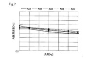
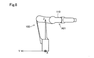
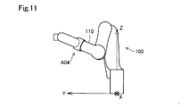
図7は、動作においてアーム110が先端170において支持する物体の質量に応じた共振周波数の変化を示すグラフである。図8〜図12は、ぞれぞれロボット100の姿勢A01〜A05を示す図である。図7において、太い実線は、ロボット100が姿勢A01をとった場合のアーム110が先端170において支持する物の質量に応じた共振周波数の変化を示すグラフである。一点鎖線は、ロボット100が姿勢A02をとった場合のアーム110が先端170において支持する物の質量に応じた共振周波数の変化を示すグラフである。細い実線は、ロボット100が姿勢A03をとった場合のアーム110が先端170において支持する物の質量に応じた共振周波数の変化を示すグラフである。破線は、ロボット100が姿勢A04をとった場合のアーム110が先端170において支持する物の質量に応じた共振周波数の変化を示すグラフである。二点鎖線は、ロボット100が姿勢A05をとった場合のアーム110が先端170において支持する物の質量に応じた共振周波数の変化を示すグラフである。
FIG. 7 is a graph showing a change in resonance frequency according to the mass of an object supported by the
図7より、いずれの姿勢においても、アーム110が先端170において支持する物の質量が大きいほど、共振周波数がが小さくなっていることが分かる。また、付加の増加分に対する虚心周波数の減少分の割合も、ほぼ一定であることが分かる。なお、図7に示す測定において、アーム110が先端170において支持する物の質量には、エンドエフェクター200の質量と、エンドエフェクター200が保持するワークピースW01の質量とが含まれる。
From FIG. 7, it can be seen that in any posture, the larger the mass of the object supported by the
第2実施形態においては、フィルター設定部345(図2参照)は、アーム110が先端170において支持する物の質量の情報に基づいて、その質量が大きいほど、第1制御信号CS1から低減すべき周波数が小さくなるように、第1制御信号CS1から低減すべき周波数を決定する。より具体的には、フィルター設定部345は、参照情報306(図1および図5参照)を参照して得られた周波数を、支持する物の質量の増加に対して、線形に減少するように、補正する。なお、アーム110が先端170において支持する物の質量の情報は、図3のステップS200において、動作が決定された際に、あらかじめロボット制御装置300に入力されている。
In the second embodiment, the filter setting unit 345 (see FIG. 2) should reduce from the first control signal CS1 as the mass increases, based on the information on the mass of the object supported by the
フィルター処理部340は、フィルター設定部345から除去すべき1以上の周波数成分の制御信号を受信し、その周波数成分を除去する処理を行って、新たなトルク制御信号を生成する(図2参照)。その結果、アーム110が先端170において支持する物の質量が大きいほど、第1制御信号CS1から低減すべき周波数の成分が小さくなるように、第1制御信号CS1が補正されて、第2制御信号CS2が生成される。
The
このような処理を行うことにより、アーム110が先端において支持する物の質量を考慮せずに、第1制御信号CS1から低減すべき周波数の成分を決定する態様に比べて、より高度にロボット100の動作の振動を低減することができる。
By performing such processing, the
C.第3実施形態:
図13は、複数のプロセッサーによってロボットの制御装置が構成される一例を示す概念図である。この例では、ロボット100およびそのロボット制御装置300の他に、パーソナルコンピューター400,400bと、LANなどのネットワーク環境を介して提供されるクラウドサービス500とが描かれている。パーソナルコンピューター400,400bは、それぞれプロセッサーとメモリーとを含んでいる。また、クラウドサービス500においてもプロセッサーとメモリーを利用可能である。プロセッサーは、コンピューター実行可能な命令を実行する。これらの複数のプロセッサーの一部または全部を利用して、ロボット制御装置300および教示装置600を含む制御装置を実現することが可能である。また、各種の情報を記憶する記憶部も、これらの複数のメモリーの一部または全部を利用して、実現することが可能である。
C. Third Embodiment:
FIG. 13 is a conceptual diagram showing an example in which a robot control device is configured by a plurality of processors. In this example, in addition to the
D.第4実施形態:
図14は、複数のプロセッサーによってロボットの制御装置が構成される他の例を示す概念図である。この例では、ロボット100のロボット制御装置300が、ロボット100の中に格納されている点が図13と異なる。この例においても、複数のプロセッサーの一部または全部を利用して、ロボット100の制御装置を実現することが可能である。また、各種の情報を記憶する記憶部も、複数のメモリーの一部または全部を利用して、実現することが可能である。
D. Fourth Embodiment:
FIG. 14 is a conceptual diagram showing another example in which a robot control device is configured by a plurality of processors. This example differs from FIG. 13 in that the
E.他の実施形態:
本開示は、上述した実施形態に限られるものではなく、その趣旨を逸脱しない範囲において種々の形態で実現することができる。例えば、本開示は、以下の形態によっても実現可能である。以下に記載した各形態中の技術的特徴に対応する上記実施形態中の技術的特徴は、本開示の課題の一部又は全部を解決するために、あるいは、本開示の効果の一部又は全部を達成するために、適宜、差し替えや、組み合わせを行うことが可能である。また、その技術的特徴が本明細書中に必須なものとして説明されていなければ、適宜、削除することが可能である。
E. Other embodiments:
The present disclosure is not limited to the above-described embodiment, and can be realized in various forms without departing from the spirit thereof. For example, the present disclosure can also be realized by the following forms. The technical features in each of the embodiments described below correspond to the technical features in the above embodiments in order to solve some or all of the problems of the present disclosure, or some or all of the effects of the present disclosure. It is possible to replace or combine as appropriate to achieve the above. Further, if the technical feature is not described as essential in the present specification, it can be appropriately deleted.
E1.他の形態1:
(1)上記実施形態においては、関節X12の位置を基準点O2として、位置の範囲Ar0,Ar1,Ar2が定められている(図4参照)。しかし、参照情報において低減すべき周波数と対応づけられる位置の範囲は、他の点を基準として定められることもできる。ただし、参照情報において低減すべき周波数と対応づけられる位置の範囲は、ロボットにおいて可動部としてのアームを支持する基台に最も近い曲げ関節の位置を中心とする範囲であることが好ましい。そのような態様とすることにより、よりアームの先端に近い関節の位置を基準点とする態様に比べて、アームに発生する様々な固有振動数の振動を、有効に低減することができる。
E1. Other form 1:
(1) In the above embodiment, the range of positions Ar0, Ar1, Ar2 is defined with the position of the joint X12 as the reference point O2 (see FIG. 4). However, the range of positions associated with the frequencies to be reduced in the reference information can also be determined with reference to other points. However, the range of the position associated with the frequency to be reduced in the reference information is preferably the range centered on the position of the bending joint closest to the base that supports the arm as a movable part in the robot. With such an embodiment, it is possible to effectively reduce the vibrations of various natural frequencies generated in the arm as compared with the embodiment in which the position of the joint closer to the tip of the arm is used as the reference point.
上記実施形態においては、参照情報において低減すべき周波数と対応づけられる位置の範囲は、基台180に最も近い関節X11における角度位置を考慮せずに定められている(図4参照)。しかし、基台180に最も近い関節X11はねじり関節であることから、関節X11における角度位置がアーム110の共振に与える影響は大きくない。このため、ロボットにおいて可動部としてのアームを支持する基台に最も近い曲げ関節の位置を基準として、低減すべき周波数と対応づけられる位置の範囲を定めることで、実質的に、ロボット100のアーム110を低減することができる。
In the above embodiment, the range of positions associated with the frequencies to be reduced in the reference information is determined without considering the angular position at the joint X11 closest to the base 180 (see FIG. 4). However, since the joint X11 closest to the
ただし、ロボット100が、架台からつり下げられて運用される場合には、基台に最も近い曲げ関節よりもさらに基台に近いねじり関節における角度位置も考慮して、共振周波数の各測定位置を定め(図4参照)、低減すべき周波数と対応づけられる位置の範囲を定めることが好ましい。なお、ロボットの製造段階(図3のS100参照)においてあらかじめ上記実施形態のように参照情報を生成し、さらに、ロボットを設置した段階(図3のS200参照)で共振周波数を測定して、追加的な参照情報を生成することもできる。
However, when the
上記実施形態においては、制御点TCPの位置に応じて低減すべき周波数が定められる(図4および図5参照)。そして、関節X13〜X16についてのアーム110の姿勢は、参照情報を参照して行われる低減すべき周波数の決定において、考慮されていない。しかし、制御点TCPの基準点に対する相対位置がアーム110の振動に与える影響は、関節X13〜X16についてのアーム110の姿勢がアーム110の振動に与える影響に比べて、非常に大きい。このため、制御点と基準点の相対位置に基づいて、低減すべき周波数と対応づけられる位置の範囲を定めることで、実質的に、ロボット100のアーム110を低減することができる。
In the above embodiment, the frequency to be reduced is determined according to the position of the control point TCP (see FIGS. 4 and 5). The posture of the
(2)上記実施形態においては、共振周波数の測定は、アーム110の先端170に取りつけられた6軸の加速度センサーを使用して行われる(図4参照)。しかし、共振周波数の測定は、アームに取りつけられた力覚センサーを使用して行われてもよい。
(2) In the above embodiment, the measurement of the resonance frequency is performed using a 6-axis acceleration sensor attached to the
(3)上記実施形態においては、非低減範囲Ar0は、円錐の形状を有する空間である(図4および図5参照)。第1範囲Ar1は、基準点O2を中心とする球状の空間から、非低減範囲Ar0を除いた空間である。第2範囲Ar2は、非低減範囲Ar0および第1範囲Ar1以外の空間である。 (3) In the above embodiment, the non-reduction range Ar0 is a space having a conical shape (see FIGS. 4 and 5). The first range Ar1 is a space obtained by removing the non-reduction range Ar0 from the spherical space centered on the reference point O2. The second range Ar2 is a space other than the non-reduction range Ar0 and the first range Ar1.
しかし、参照情報において、低減すべき周波数と対応づけられる空間は、他の形状を有していてもよい。低減すべき周波数と対応づけられる空間の数は、3以上であってもよい。また、低減すべき周波数と対応づけられる空間は、ロボット座標系のZ軸を基準とする極座標系で定められてもよい。ただし、低減すべき周波数と対応づけられる空間は、ロボットが備える複数の関節のうち、基台に最も近い曲げ関節を基準点として、基準点からの距離に応じて定められることが好ましい。また、低減すべき周波数と対応づけられる空間は、互いに重複しないことが好ましい。 However, in the reference information, the space associated with the frequency to be reduced may have other shapes. The number of spaces associated with the frequency to be reduced may be 3 or more. Further, the space associated with the frequency to be reduced may be defined by a polar coordinate system based on the Z axis of the robot coordinate system. However, the space associated with the frequency to be reduced is preferably determined according to the distance from the reference point, with the bending joint closest to the base as the reference point among the plurality of joints provided in the robot. Further, it is preferable that the spaces associated with the frequencies to be reduced do not overlap with each other.
(4)上記実施形態においては、ロボット100の各曲げ関節X12,X13,X15において、回転軸は、一方のみで支持されている(図1参照)。このような態様においては、回転軸が両端で支持されている態様に比べて、関節の剛性が低いため、振動が生じやすい。このため、本開示の技術は、関節の回転軸が一方のみで支持されているロボットにおいて特に有効である。ただし、本開示の技術は、関節の回転軸が両方で支持されているロボットに適用しても、有効な効果が得られる。
(4) In the above embodiment, in each of the bending joints X12, X13, and X15 of the
(5)上記実施形態においては、ロボット100は、垂直多関節ロボットである(図1参照)。しかし、本開示の技術は、いわゆるスカラロボットに適用することもできる。
(5) In the above embodiment, the
(6)上記実施形態においては、振動低減処理において、参照情報306を参照して定められる周波数F11,F21およびそれらの前後の周波数成分のみが低減される態様を説明した(図6参照)。しかし、振動低減処理において、参照情報を参照して定められる周波数およびそれらの前後の周波数成分に加えて、他の周波数成分を低減する態様とすることもできる。低減されるべき他の周波数成分は、たとえば、ロボットのアームにエンドエフェクターを取りつけた後に、共振周波数を測定して、得られた共振周波数に基づいて定めることができる。 (6) In the above embodiment, in the vibration reduction processing, only the frequencies F11 and F21 determined with reference to the reference information 306 and the frequency components before and after them are reduced (see FIG. 6). However, in the vibration reduction processing, in addition to the frequencies determined by referring to the reference information and the frequency components before and after them, other frequency components may be reduced. Other frequency components to be reduced can be determined, for example, based on the resulting resonance frequency by measuring the resonance frequency after attaching the end effector to the robot arm.
参照情報を参照して定められる周波数の低減の処理と、他の方法で定められる周波数の低減の処理とは、異なる動作において実行されてもよいし、同一の動作内で実行されてもよい。また、並行して実行されてもよいし、前後して実行されてもよい。 The frequency reduction process determined by referring to the reference information and the frequency reduction process determined by another method may be executed in different operations or may be executed in the same operation. Moreover, it may be executed in parallel, or may be executed before and after.
E2.他の形態2:
上記実施形態においては、制御点TCPは、ロボット100のアーム110の先端170にある(図1参照)。しかし、ロボットの制御点は、たとえば、アームの先端から基台側の位置など、可動部としてのアームの先端からずれた位置に配することもできる。
E2. Other form 2:
In the above embodiment, the control point TCP is located at the
E3.他の形態3:
上記実施形態においては、F11,F21の周波数±Δfの範囲の周波数成分が、低減される。Δfは1Hzである。しかし、特定の周波数の成分とともに低減されるその前後の周波数の幅は、0.5Hzや2Hzなど、他の値でもよい。また、特定の周波数の成分とともに低減されるその前後の周波数の幅は、特定の周波数の成分ごとに異なっていてもよい。
E3. Other form 3:
In the above embodiment, the frequency components in the frequency range ± Δf of F11 and F21 are reduced. Δf is 1 Hz. However, the width of the frequency before and after the reduction with the component of the specific frequency may be another value such as 0.5 Hz or 2 Hz. Further, the width of the frequency before and after the reduction with the component of the specific frequency may be different for each component of the specific frequency.
E4.他の形態4:
上記実施形態においては、「種類」の欄が「通常」に設定されている場合には、フィルター設定部345(図2参照)は、振動低減処理において低減すべき周波数として、動作の終点が属する位置の範囲に対応づけられた周波数を、決定する(図6の番号1参照)。そして、「種類」の欄は、デフォルトでは、「通常」に設定される。しかし、振動低減処理において低減すべき周波数として、動作の終点が属する位置の範囲に対応づけられた周波数を、デフォルトとしない態様とすることもできる。そして、振動低減処理において低減すべき周波数として、動作の終点が属する位置の範囲に対応づけられた周波数を、決定せず、他の周波数を決定する態様とすることもできる。たとえば、振動低減処理において低減すべき周波数として、動作の始点が属する位置の範囲に対応づけられた周波数のみを、決定してもよい。また、振動低減処理において低減すべき周波数として、速度が変更される変更点が属する位置の範囲に対応づけられた周波数のみを、決定してもよい。
E4. Other form 4:
In the above embodiment, when the "type" column is set to "normal", the filter setting unit 345 (see FIG. 2) belongs to the end point of operation as the frequency to be reduced in the vibration reduction processing. The frequency associated with the range of positions is determined (see
E5.他の形態5:
上記実施形態においては、フィルター処理部340(図2参照)は、動作Op10を指示する第1制御信号CS1から、参照情報306において第2範囲Ar2と対応づけられている周波数F21の成分と、第1範囲Ar1と対応づけられている周波数F11の成分と、を低減して、第2制御信号CS2を生成する(図6の番号2欄のParam1,Param2参照)。
E5. Other form 5:
In the above embodiment, the filter processing unit 340 (see FIG. 2) receives the component of the frequency F21 associated with the second range Ar2 in the reference information 306 from the first control signal CS1 instructing the operation Op10, and the first. The second control signal CS2 is generated by reducing the component of the frequency F11 associated with the one range Ar1 (see Param1 and Param2 in
たとえば、ある動作が3以上の位置の範囲内を通る場合には、それらのうちのどの位置の範囲に対応づけられた周波数を、振動低減処理において低減すべきかを、選択できる態様とすることもできる。ただし、振動低減処理において、4以上の周波数成分を低減すると、位置偏差が大きくなるため、好ましくない。 For example, when a certain operation passes within the range of three or more positions, it is possible to select which of the range of positions the frequency associated with the vibration reduction process should be reduced. it can. However, in the vibration reduction processing, if the frequency components of 4 or more are reduced, the position deviation becomes large, which is not preferable.
E6.他の形態6:
(1)上記実施形態においては、「種類」の欄が「境界切替え」に設定されている場合には、フィルター処理部340は、第1制御信号CS1のうち、制御点TCPが第1範囲Ar1内を移動する第1部分動作Op11を指示する部分について、参照情報306において第1範囲Ar1と対応づけられている周波数F11の成分を低減する(図4および図6参照)。そして、フィルター処理部340は、第1制御信号CS1のうち、制御点TCPが第2範囲Ar2内を移動する第2部分動作Op12を指示する部分について、参照情報306において第2範囲Ar2と対応づけられている周波数F21の成分を低減する。このような位置の範囲の境界における切換は、ある動作が3以上の位置の範囲内を通る場合についても、実行されることができる。
E6. Other form 6:
(1) In the above embodiment, when the "type" column is set to "boundary switching", the
また、第1範囲Ar1内の位置P31から、非低減範囲Ar0内の位置P32に、制御点TCPが移動する動作Op30については、第1範囲Ar1と対応づけられている周波数F11の成分を低減する処理と、周波数の成分を低減しない処理と、制御点が位置する位置の範囲Ar1,Ar0に応じて切り替えることもできる。 Further, for the operation Op30 in which the control point TCP moves from the position P31 in the first range Ar1 to the position P32 in the non-reduction range Ar0, the component of the frequency F11 associated with the first range Ar1 is reduced. It is also possible to switch between processing and processing that does not reduce the frequency component, depending on the range Ar1 and Ar0 of the position where the control point is located.
また、低減する周波数を切り替える際には、もとの周波数を低減する割合を低減するとともに、新たな周波数を低減する割合を増加させて、徐々に切換を行うことが好ましい。 Further, when switching the frequency to be reduced, it is preferable to reduce the rate of reducing the original frequency and increase the rate of reducing the new frequency to gradually switch.
(2)上記実施形態においては、「種類」の欄においては、「通常」、「両方」、「境界切替え」、および「変速点切替え」の4個の選択肢の中から一つが選択される(図6参照)。しかし、そのような選択をすることができず、「通常」、「両方」、「境界切替え」、および「変速点切替え」のいずれかに対応する処理のみを行う制御装置として、本開示の技術を適用することもできる。 (2) In the above embodiment, in the "type" column, one is selected from four options of "normal", "both", "boundary switching", and "shift point switching" (1). (See FIG. 6). However, the technique of the present disclosure is a control device that cannot make such a selection and performs only processing corresponding to any of "normal", "both", "boundary switching", and "shift point switching". Can also be applied.
E7.他の形態7:
(1)上記実施形態においては、「種類」の欄が「変更点切替え」に設定されている場合には、フィルター処理部340は、第1制御信号CS1のうち、制御点TCPが変更点P23に達する前の動作である第1部分動作Op21を指示する部分について、参照情報306において第1範囲Ar1と対応づけられている周波数F11の成分を低減する。フィルター処理部340は、第1制御信号CS1のうち、制御点TCPが変更点P23に達した後の動作である第2部分動作Op22を指示する部分について、参照情報306において第2範囲Ar2と対応づけられている周波数F21の成分を低減する。変更点P23は、第2範囲Ar2内にある。
E7. Other form 7:
(1) In the above embodiment, when the "type" column is set to "change point switching", the
しかし、変更点P23は、第2範囲Ar2内ではなく、第1範囲Ar1内にある場合にも、上記の処理を行うこともできる。 However, the above processing can be performed even when the change P23 is not in the second range Ar2 but in the first range Ar1.
(2)上記実施形態においては、制御点の速度が変更される変更点は動作Op20において一点P23である(図4参照)。しかし、複数の変更点が、一つの動作中に含まれていてもよい。変更点が含まれる動作においては、変更点以降の動作についての振動低減処理において、変更点が属する位置の範囲が対応づけられている周波数が低減されてもよいし、動作の終点が属する位置の範囲が対応づけられている周波数が低減されてもよい。 (2) In the above embodiment, the change in which the speed of the control point is changed is one point P23 in the operation Op20 (see FIG. 4). However, a plurality of changes may be included in one operation. In the operation including the change point, in the vibration reduction processing for the operation after the change point, the frequency to which the range of the position to which the change point belongs may be reduced, or the frequency to which the end point of the operation belongs may be reduced. The frequencies to which the ranges are associated may be reduced.
E8.他の形態8:
上記実施形態において、動作Op30は、第1範囲Ar1内の位置P31から、非低減範囲Ar0内の位置P32に、制御点TCPが移動する動作である(図4の下段右部参照)。このように、参照情報を使用した振動低減処理を行わない動作は、動作Op30のように、動作の一部において、非低減範囲を通過する動作であってもよい。また、参照情報を使用した振動低減処理を行わない動作は、非低減範囲内のみを制御点が移動する動作としてもよい。
E8. Other form 8:
In the above embodiment, the operation Op30 is an operation in which the control point TCP moves from the position P31 in the first range Ar1 to the position P32 in the non-reduction range Ar0 (see the lower right part of FIG. 4). As described above, the operation that does not perform the vibration reduction processing using the reference information may be an operation that passes through the non-reduction range in a part of the operation, such as the operation Op30. Further, the operation in which the vibration reduction processing using the reference information is not performed may be an operation in which the control point moves only within the non-reduction range.
E9.他の形態9:
上記実施形態においては、非低減範囲Ar0には、基台180が含まれる(図4参照)。しかし、周波数と対応づけられていないロボットの制御点の位置の範囲である非低減範囲は、基台の一部を含まない範囲とすることもでき、基台の全部を含まない範囲とすることもできる。また、非低減範囲を有さない参照情報を作成することもできる。
E9. Other form 9:
In the above embodiment, the non-reduction range Ar0 includes the base 180 (see FIG. 4). However, the non-reduction range, which is the range of the position of the control point of the robot that is not associated with the frequency, can be a range that does not include a part of the base, and a range that does not include the entire base. You can also. It is also possible to create reference information having no non-reduction range.
E10.他の形態10:
第2実施形態においては、フィルター設定部345は、参照情報306(図1および図5参照)を参照して得られた周波数を、支持する物の質量の増加に対して、線形に減少するように、補正する(図7参照)。しかし、参照情報を参照して得られた周波数は、たとえば、上に凸または下に凸の2次曲線的に補正されるなど、他の方法で補正されることもできる。
E10. Other form 10:
In the second embodiment, the
また、考慮される質量は、エンドエフェクター200が保持するワークピースW01の質量以外に、アーム110に取りつけられるセンサーや、工具や、モニターの質量を含むことができる。それらの質量を含めて、参照情報を参照して得られた周波数を補正する場合には、たとえば、それらの物体が取りつけられている位置に応じて、それらの質量にかける係数を変えて、重み付け和に基づいて、周波数を補正することが好ましい。
Further, the mass to be considered may include the mass of the sensor, the tool, and the monitor attached to the
F.さらに他の形態:
本開示は、上述した実施形態に限られるものではなく、その趣旨を逸脱しない範囲において種々の形態で実現することができる。例えば、本開示は、以下の形態(aspect)によっても実現可能である。以下に記載した各形態中の技術的特徴に対応する上記実施形態中の技術的特徴は、本開示の課題の一部又は全部を解決するために、あるいは、本開示の効果の一部又は全部を達成するために、適宜、差し替えや、組み合わせを行うことが可能である。また、その技術的特徴が本明細書中に必須なものとして説明されていなければ、適宜、削除することが可能である。
F. Yet other forms:
The present disclosure is not limited to the above-described embodiment, and can be realized in various forms without departing from the spirit thereof. For example, the present disclosure can also be realized by the following aspect. The technical features in each of the embodiments described below correspond to the technical features in the above embodiments in order to solve some or all of the problems of the present disclosure, or some or all of the effects of the present disclosure. It is possible to replace or combine as appropriate to achieve the above. Further, if the technical feature is not described as essential in the present specification, it can be appropriately deleted.
(1)本開示の一形態によれば、ロボットを制御するための制御装置が提供される。この制御装置は、ロボットの可動部を移動させる動作を行うための第1制御信号から、あらかじめ定められた周波数の成分を低減して第2制御信号を生成することができる第2制御信号生成部と、前記ロボットの制御点の位置の範囲と周波数との組み合わせの情報を含む参照情報を記憶している記憶部と、を備え、前記第2制御信号生成部は、前記動作における前記ロボットの制御点の位置に基づいて、前記参照情報を参照して、前記第1制御信号から低減すべき周波数の成分を決定する。
このような態様とすれば、新たに教示した動作についてロボットの共振周波数を測定することなく、その動作について、振動を低減できる駆動信号を生成してロボットに出力することができる。このため、ロボットの制御点の位置の範囲と周波数成分との組み合わせの情報を含む参照情報を使用した第2制御信号の生成を行わない制御装置に比べて、複数の動作について振動を低減する際のユーザーの負荷を低減することができる。
(1) According to one embodiment of the present disclosure, a control device for controlling a robot is provided. This control device is a second control signal generation unit capable of generating a second control signal by reducing a predetermined frequency component from the first control signal for performing an operation of moving a movable part of the robot. A storage unit that stores reference information including information on a combination of a range of positions of control points of the robot and a frequency is provided, and the second control signal generation unit controls the robot in the operation. Based on the position of the point, the reference information is referred to to determine the frequency component to be reduced from the first control signal.
In such an embodiment, it is possible to generate a drive signal capable of reducing vibration for the newly taught motion without measuring the resonance frequency of the robot and output it to the robot. For this reason, when reducing vibration for a plurality of operations, as compared with a control device that does not generate a second control signal using reference information including information on the combination of the position range of the control point of the robot and the frequency component. The load on the user can be reduced.
(2)上記形態の制御装置において、前記制御点は、前記可動部の両端のうち、前記可動部を支持する基台と接続されている端とは逆の端にある、態様とすることもできる。
このような態様とすれば、ロボットの設計情報に基づいて参照情報を生成して、その参照情報に基づいて有効にロボットの振動を低減することができる。
(2) In the control device of the above embodiment, the control point may be at the end of both ends of the movable portion opposite to the end connected to the base supporting the movable portion. it can.
According to such an aspect, reference information can be generated based on the design information of the robot, and the vibration of the robot can be effectively reduced based on the reference information.
(3)上記形態の制御装置において、前記第2制御信号生成部は、前記決定した周波数を含むあらかじめ定められた幅の周波数の範囲の成分を、前記第1制御信号から低減して、前記第2制御信号を生成し、前記参照情報は、前記ロボットの制御点の位置の範囲と周波数との2以上の組み合わせの情報を含み、前記参照情報において、任意の二つの前記位置の範囲は、それぞれ対応づけられた前記周波数を含む前記周波数の範囲が互いに重複しないように設定されている、態様とすることもできる。
このような態様とすれば、第2制御信号生成部が低減する周波数の範囲が重複する態様に比べて、共振周波数となり得る周波数の範囲について、より少ない数の位置の範囲の区分で、効率的に振動を低減できるように、参照情報を生成することができる。
(3) In the control device of the above embodiment, the second control signal generation unit reduces components in a frequency range having a predetermined width including the determined frequency from the first control signal, and the first control signal is generated. Two control signals are generated, the reference information includes information on two or more combinations of a range of positions of control points of the robot and a frequency, and in the reference information, any two ranges of the positions are each. It can also be an embodiment in which the frequency ranges including the associated frequencies are set so as not to overlap each other.
In such an embodiment, as compared with the embodiment in which the frequency ranges reduced by the second control signal generator overlap, the frequency range that can be the resonance frequency can be divided into a smaller number of position ranges, which is more efficient. Reference information can be generated so that vibration can be reduced.
(4)上記形態の制御装置において、前記参照情報は、周波数と対応づけられた位置の範囲である第1範囲と、周波数と対応づけられた位置の範囲であって前記第1範囲とは異なる第2範囲と、の情報を含み、前記第2制御信号生成部は、前記第1範囲内の位置から前記第2範囲内の位置に前記制御点が移動する動作を指示する前記第1制御信号から、前記参照情報において前記第2範囲と対応づけられている周波数の成分を低減して、前記第2制御信号を生成する、態様とすることもできる。
このような態様とすれば、第1制御信号で指示される動作が終了した後の残留振動を、効果的に低減できる、第2制御信号を生成することができる。
(4) In the control device of the above embodiment, the reference information is a first range which is a range of positions associated with a frequency and a range of positions associated with a frequency, which is different from the first range. The second control signal generation unit includes the information of the second range, and the second control signal generation unit instructs the operation of moving the control point from the position in the first range to the position in the second range. Therefore, it is also possible to reduce the frequency component associated with the second range in the reference information to generate the second control signal.
According to such an embodiment, it is possible to generate a second control signal capable of effectively reducing the residual vibration after the operation indicated by the first control signal is completed.
(5)上記形態の制御装置において、前記第2制御信号生成部は、前記第1制御信号から、さらに、前記参照情報において前記第1範囲と対応づけられている周波数の成分を低減して、前記第2制御信号を生成する、態様とすることもできる。
このような態様とすれば、さらに、制御点が第1範囲を移動しているときの制御点の振動を、効果的に低減できる、第2制御信号を生成することができる。
(5) In the control device of the above embodiment, the second control signal generation unit further reduces the frequency component associated with the first range in the reference information from the first control signal. It can also be an embodiment that generates the second control signal.
In such an aspect, it is possible to further generate a second control signal capable of effectively reducing the vibration of the control point when the control point is moving in the first range.
(6)上記形態の制御装置において、前記参照情報は、周波数と対応づけられた位置の範囲である第1範囲と、周波数と対応づけられた位置の範囲であって前記第1範囲とは異なる第2範囲と、の情報を含み、前記第2制御信号生成部は、前記第1範囲内の位置から前記第2範囲内の位置に前記制御点が移動する動作を指示する前記第1制御信号から、前記第2制御信号を生成する際に、前記第1制御信号のうち、前記制御点が前記第1範囲内を移動する第1部分動作を指示する部分について、前記参照情報において前記第1範囲と対応づけられている周波数の成分を低減し、前記第1制御信号のうち、前記制御点が前記第2範囲内を移動する第2部分動作を指示する部分について、前記参照情報において前記第2範囲と対応づけられている周波数の成分を低減する、態様とすることもできる。
このような態様とすれば、第1範囲と対応づけられている周波数の成分と第2範囲と対応づけられている周波数の成分との両方を、一貫して低減する態様に比べて、位置ずれを少なくしつつ、第1制御信号が指示する動作のうちの第1部分動作について、振動を効果的に低減することができ、第2部分動作についても、振動を効果的に低減することができる。
(6) In the control device of the above-described embodiment, the reference information is a first range which is a range of positions associated with a frequency and a range of positions associated with a frequency, which is different from the first range. The second control signal generation unit includes the information of the second range, and the first control signal generating unit instructs the operation of moving the control point from the position in the first range to the position in the second range. Therefore, when the second control signal is generated, the portion of the first control signal that instructs the first part operation in which the control point moves within the first range is described in the reference information. In the reference information, the second part of the first control signal, which reduces the frequency component associated with the range and instructs the second part operation in which the control point moves within the second range, is described. It can also be an embodiment that reduces the frequency components associated with the two ranges.
In such an embodiment, the misalignment is compared with the embodiment in which both the frequency component associated with the first range and the frequency component associated with the second range are consistently reduced. The vibration can be effectively reduced for the first partial operation of the operations indicated by the first control signal, and the vibration can be effectively reduced for the second partial operation as well. ..
(7)上記形態の制御装置において、前記参照情報は、周波数と対応づけられた位置の範囲である第1範囲と、周波数と対応づけられた位置の範囲であって前記第1範囲とは異なる第2範囲と、の情報を含み、前記第2制御信号生成部は、前記第1範囲内の位置から前記第2範囲内の位置に前記制御点が移動する動作であって、前記第2範囲内のあらかじめ定められた変更点において前記制御点の速度を変えて移動する動作を指示する前記第1制御信号から、前記第2制御信号を生成する際に、前記第1制御信号のうち、前記制御点が前記変更点に達する前の動作である第1部分動作を指示する部分について、前記参照情報において前記第1範囲と対応づけられている周波数の成分を低減し、前記第1制御信号のうち、前記制御点が前記変更点に達した後の動作である第2部分動作を指示する部分について、前記参照情報において前記第2範囲と対応づけられている周波数の成分を低減する、態様とすることもできる。
このような態様とすれば、第1範囲と対応づけられている周波数の成分と第2範囲と対応づけられている周波数の成分との両方を、一貫して低減する態様に比べて、位置ずれを少なくしつつ、第1制御信号が指示する動作のうちの第1部分動作について、振動を効果的に低減することができ、第2部分動作についても、振動を効果的に低減することができる。
(7) In the control device of the above-described embodiment, the reference information is a first range which is a range of positions associated with a frequency and a range of positions associated with a frequency, which is different from the first range. The second control signal generation unit includes information on the second range, and is an operation in which the control point moves from a position in the first range to a position in the second range, and the second range. Among the first control signals, when the second control signal is generated from the first control signal instructing an operation of changing the speed of the control point at a predetermined change point in the above. Regarding the part instructing the first part operation, which is the operation before the control point reaches the change point, the frequency component associated with the first range in the reference information is reduced, and the first control signal Among them, with respect to the portion instructing the second partial operation, which is the operation after the control point reaches the change point, the component of the frequency associated with the second range in the reference information is reduced. You can also do it.
In such an embodiment, the misalignment is compared with the embodiment in which both the frequency component associated with the first range and the frequency component associated with the second range are consistently reduced. The vibration can be effectively reduced for the first partial operation of the operations indicated by the first control signal, and the vibration can be effectively reduced for the second partial operation as well. ..
(8)上記形態の制御装置において、前記参照情報は、さらに、周波数と対応づけられていない前記ロボットの制御点の位置の範囲である非低減範囲の情報を含み、前記第2制御信号生成部は、前記制御点が前記非低減範囲を移動する動作を指示する前記第1制御信号から、周波数の成分を低減することなく、前記第2制御信号を生成することができる、態様とすることもできる。
このような態様とすれば、制御点がどのような位置範囲にある動作についても、第1制御信号から周波数の成分を低減する態様に比べて、制御点が非低減範囲内を移動する動作における位置精度を向上させることができる。
(8) In the control device of the above embodiment, the reference information further includes information in a non-reduced range which is a range of positions of control points of the robot which is not associated with a frequency, and the second control signal generation unit. Can also be an embodiment in which the second control signal can be generated from the first control signal instructing the operation of the control point moving in the non-reduction range without reducing the frequency component. it can.
According to such an embodiment, the operation in which the control point is in any position range is in the operation in which the control point moves within the non-reduction range as compared with the embodiment in which the frequency component is reduced from the first control signal. Positional accuracy can be improved.
(9)上記形態の制御装置において、前記非低減範囲は、前記可動部を支持する基台の少なくとも一部を含む範囲である、態様とすることもできる。
このような態様においては、制御点が可動部を支持している基台の近傍にあり、可動部が折り畳まれている姿勢をとる動作の第1制御信号については、周波数の成分が低減されることなく、第2制御信号が生成される。このため、可動部が折り畳まれており、振動しにくいと考えられる動作について、振動による不利益を被ることなく、または少ない不利益で、位置精度を向上させることができる。
(9) In the control device of the above embodiment, the non-reduction range may be a range including at least a part of the base supporting the movable portion.
In such an embodiment, the frequency component is reduced for the first control signal of the operation in which the control point is near the base supporting the movable portion and the movable portion takes a folded posture. The second control signal is generated without any problem. Therefore, the position accuracy can be improved without suffering a disadvantage due to vibration or with a small disadvantage for an operation in which the movable portion is folded and is considered to be difficult to vibrate.
(10)上記形態の制御装置において、前記第2制御信号生成部は、前記可動部が支持する物の質量の情報に基づいて、前記質量が大きいほど、前記第1制御信号から低減すべき周波数の成分が小さくなるように、前記第1制御信号から低減すべき周波数の成分を決定する、態様とすることもできる。
このような態様とすれば、可動部が支持する物の質量を考慮せずに、第1制御信号から低減すべき周波数の成分を決定する態様に比べて、より高度にロボットの動作の振動を低減することができる。
(10) In the control device of the above embodiment, the second control signal generation unit has a frequency to be reduced from the first control signal as the mass increases, based on information on the mass of the object supported by the movable unit. It is also possible to determine the component of the frequency to be reduced from the first control signal so that the component of is small.
In such an embodiment, the vibration of the robot operation can be performed to a higher degree than in the embodiment in which the frequency component to be reduced is determined from the first control signal without considering the mass of the object supported by the moving part. It can be reduced.
(11)本開示の他の形態によれば、ロボットを制御する制御方法が提供される。この制御方法は、(a)ロボットの制御点の位置の範囲と周波数との組み合わせの情報を含む参照情報を準備する工程と、(b)動作における前記ロボットの制御点の位置に基づいて、前記参照情報を参照して、前記ロボットの可動部を移動させる動作を行うための第1制御信号から低減すべき周波数の成分を決定する工程と、(c)前記第1制御信号から、前記決定された周波数の成分を低減して第2制御信号を生成する工程と、(d)前記第2制御信号に基づいて、前記ロボットを駆動する駆動信号を生成する工程と、を含む。 (11) According to another aspect of the present disclosure, a control method for controlling a robot is provided. This control method is based on (a) the step of preparing reference information including information on the combination of the range of the position of the control point of the robot and the frequency, and (b) the position of the control point of the robot in the operation. The step of determining the frequency component to be reduced from the first control signal for performing the operation of moving the movable part of the robot with reference to the reference information, and (c) the determination from the first control signal. It includes a step of generating a second control signal by reducing a component of the frequency, and (d) a step of generating a drive signal for driving the robot based on the second control signal.
(12)上記形態の制御方法において、前記制御点は、前記可動部の両端のうち、前記可動部を支持する基台と接続されている端とは逆の端にある、態様とすることもできる。 (12) In the control method of the above embodiment, the control point may be at the end of both ends of the movable portion opposite to the end connected to the base supporting the movable portion. it can.
(13)上記形態の制御方法において、前記工程(c)は、前記決定された周波数を含むあらかじめ定められた幅の周波数の範囲の成分を、前記第1制御信号から低減して、前記第2制御信号を生成する工程であり、前記工程(a)は、前記ロボットの制御点の位置の範囲と周波数との2以上の組み合わせの情報を含み、任意の二つの前記位置の範囲は、それぞれ対応づけられた前記周波数を含む前記周波数の範囲が互いに重複しないように設定されている、前記参照情報を準備する工程である、態様とすることもできる。 (13) In the control method of the above embodiment, in the step (c), the components in the frequency range having a predetermined width including the determined frequency are reduced from the first control signal, and the second control signal is used. A step of generating a control signal, the step (a) includes information on two or more combinations of a range of positions of control points of the robot and a frequency, and any two ranges of the positions correspond to each other. It can also be an embodiment, which is a step of preparing the reference information, in which the frequency ranges including the attached frequency are set so as not to overlap each other.
(14)上記形態の制御方法において、前記参照情報は、周波数と対応づけられた位置の範囲である第1範囲と、周波数と対応づけられた位置の範囲であって前記第1範囲とは異なる第2範囲と、の情報を含み、前記工程(c)は、前記第1範囲内の位置から前記第2範囲内の位置に前記制御点が移動する動作を指示する前記第1制御信号から、前記参照情報において前記第2範囲と対応づけられている周波数の成分を低減して、前記第2制御信号を生成する工程である、態様とすることもできる。 (14) In the control method of the above embodiment, the reference information is a first range which is a range of positions associated with a frequency and a range of positions associated with a frequency, which is different from the first range. Including the information of the second range, the step (c) is based on the first control signal indicating the operation of moving the control point from the position in the first range to the position in the second range. It is also possible to make it an embodiment in which it is a step of generating the second control signal by reducing the frequency component associated with the second range in the reference information.
(15)上記形態の制御方法において、前記工程(c)は、前記第1制御信号から、さらに、前記参照情報において前記第1範囲と対応づけられている周波数の成分を低減して、前記第2制御信号を生成する工程である、態様とすることもできる。 (15) In the control method of the above embodiment, in the step (c), the component of the frequency associated with the first range in the reference information is further reduced from the first control signal, and the first step is performed. 2 It can also be an embodiment, which is a step of generating a control signal.
(16)上記形態の制御方法において、前記参照情報は、周波数と対応づけられた位置の範囲である第1範囲と、周波数と対応づけられた位置の範囲であって前記第1範囲とは異なる第2範囲と、の情報を含み、前記工程(c)は、前記第1範囲内の位置から前記第2範囲内の位置に前記制御点が移動する動作を指示する前記第1制御信号から、前記第2制御信号を生成する際に、前記第1制御信号のうち、前記制御点が前記第1範囲内を移動する第1部分動作を指示する部分について、前記参照情報において前記第1範囲と対応づけられている周波数の成分を低減し、前記第1制御信号のうち、前記制御点が前記第2範囲内を移動する第2部分動作を指示する部分について、前記参照情報において前記第2範囲と対応づけられている周波数の成分を低減する工程である、態様とすることもできる。 (16) In the control method of the above embodiment, the reference information is a first range which is a range of positions associated with a frequency and a range of positions associated with a frequency, which is different from the first range. Including the information of the second range, the step (c) is based on the first control signal indicating the operation of moving the control point from the position in the first range to the position in the second range. When the second control signal is generated, the portion of the first control signal that instructs the first partial operation in which the control point moves within the first range is referred to as the first range in the reference information. Regarding the portion of the first control signal that reduces the component of the associated frequency and instructs the second partial operation in which the control point moves within the second range, the second range in the reference information. It can also be an embodiment, which is a step of reducing the component of the frequency associated with.
(17)上記形態の制御方法において、前記参照情報は、周波数と対応づけられた位置の範囲である第1範囲と、周波数と対応づけられた位置の範囲であって前記第1範囲とは異なる第2範囲と、の情報を含み、前記工程(c)は、前記第1範囲内の位置から前記第2範囲内の位置に前記制御点が移動する動作であって、前記第2範囲内のあらかじめ定められた変更点において前記制御点の速度を変えて移動する動作を指示する前記第1制御信号から、前記第2制御信号を生成する際に、前記第1制御信号のうち、前記制御点が前記変更点に達する前の動作である第1部分動作を指示する部分について、前記参照情報において前記第1範囲と対応づけられている周波数の成分を低減し、前記第1制御信号のうち、前記制御点が前記変更点に達した後の動作である第2部分動作を指示する部分について、前記参照情報において前記第2範囲と対応づけられている周波数の成分を低減する工程である、態様とすることもできる。 (17) In the control method of the above embodiment, the reference information is a first range which is a range of positions associated with a frequency and a range of positions associated with a frequency, which is different from the first range. Including the information of the second range, the step (c) is an operation of moving the control point from a position in the first range to a position in the second range, and is within the second range. When the second control signal is generated from the first control signal instructing an operation of changing the speed of the control point at a predetermined change point, the control point among the first control signals With respect to the portion instructing the first partial operation, which is the operation before reaching the change, the frequency component associated with the first range in the reference information is reduced, and among the first control signals, A mode in which the component of the frequency associated with the second range in the reference information is reduced with respect to the portion instructing the second partial operation, which is the operation after the control point reaches the change point. It can also be.
(18)上記形態の制御方法において、前記参照情報は、さらに、周波数と対応づけられていない前記ロボットの制御点の位置の範囲である非低減範囲の情報を含み、前記工程(c)は、前記制御点が前記非低減範囲を移動する動作を指示する前記第1制御信号から、周波数の成分を低減することなく、前記第2制御信号を生成する工程を含む、態様とすることもできる。 (18) In the control method of the above embodiment, the reference information further includes information in a non-reduced range which is a range of positions of control points of the robot which is not associated with a frequency, and the step (c) is described. It is also possible to include a step of generating the second control signal from the first control signal instructing the operation of the control point moving in the non-reduction range without reducing the frequency component.
(19)上記形態の制御方法において、前記非低減範囲は、前記可動部を支持する基台の少なくとも一部を含む範囲である、態様とすることもできる。 (19) In the control method of the above embodiment, the non-reduction range may be a range including at least a part of the base supporting the movable portion.
(20)上記形態の制御方法において、前記工程(b)は、前記可動部が支持する物の質量の情報に基づいて、前記質量が大きいほど、前記第1制御信号から低減すべき周波数の成分が小さくなるように、前記第1制御信号から低減すべき周波数の成分を決定する工程である、態様とすることもできる。 (20) In the control method of the above embodiment, in the step (b), based on the information on the mass of the object supported by the movable portion, the larger the mass, the more the frequency component to be reduced from the first control signal. It can also be an embodiment which is a step of determining a frequency component to be reduced from the first control signal so that
(21)本開示の他の形態によれば、ロボットシステムが提供される。このロボットシステムは、上記の制御装置と、前記制御装置によって制御されるロボットと、を備える。 (21) According to another aspect of the present disclosure, a robot system is provided. This robot system includes the above-mentioned control device and a robot controlled by the above-mentioned control device.
本開示は、ロボット制御装置、ロボットの制御方法、およびロボットシステム以外の種々の形態で実現することも可能である。例えば、ロボットの制御方法を実現するコンピュータプログラム、そのコンピュータプログラムを記録した一時的でない記録媒体等の形態で実現することができる。 The present disclosure can also be realized in various forms other than the robot control device, the robot control method, and the robot system. For example, it can be realized in the form of a computer program that realizes a robot control method, a non-temporary recording medium that records the computer program, or the like.
上述した本開示の各形態の有する複数の構成要素はすべてが必須のものではなく、上述の課題の一部又は全部を解決するため、あるいは、本明細書に記載された効果の一部又は全部を達成するために、適宜、前記複数の構成要素の一部の構成要素について、その変更、削除、新たな他の構成要素との差し替え、限定内容の一部削除を行うことが可能である。また、上述の課題の一部又は全部を解決するため、あるいは、本明細書に記載された効果の一部又は全部を達成するために、上述した本開示の一形態に含まれる技術的特徴の一部又は全部を上述した本開示の他の形態に含まれる技術的特徴の一部又は全部と組み合わせて、本開示の独立した一形態とすることも可能である。 The plurality of components of each form of the disclosure described above are not all essential and may be used to solve some or all of the problems described above, or part or all of the effects described herein. In order to achieve the above, it is possible to change or delete some of the components of the plurality of components, replace them with new other components, and partially delete the limited contents. In addition, in order to solve a part or all of the above-mentioned problems, or to achieve a part or all of the effects described in the present specification, the technical features included in the above-mentioned embodiment of the present disclosure. It is also possible to combine some or all with some or all of the technical features contained in the other forms of the present disclosure described above to form an independent form of the present disclosure.
1…ロボットシステム、100…ロボット、110…アーム、170…先端、180…基台、190…力覚センサー、200…エンドエフェクター、300…ロボット制御装置、301…CPU、302…RAM、303…ROM、306…参照情報、310…制御信号生成部、320…位置制御部、330…速度制御部、340…フィルター処理部、345…フィルター設定部、350…トルク制御部、360…サーボアンプ、390…力制御部、400,400b…パーソナルコンピューター、410…サーボモーター、420…位置センサー、500…クラウドサービス、600…教示装置、601…CPU、602…RAM、603…ROM、604…入力装置、604a…キーボード、604b…操作レバー、604c…タッチパネル、605…出力装置、A01〜A05…ロボットの姿勢、Ar0…非低減範囲、Ar1…第1範囲、Ar2…第2範囲、CS1…第1制御信号、CS2…第2制御信号、DS…駆動信号、Dx…基準点の原点に対するX軸方向のオフセット、Dz…基準点の原点に対するZ軸方向のオフセット、F11…周波数、F21…周波数、LS…基準線、O…原点、O2…基準点、Op10…動作、Op11…第1部分動作、Op12…第2部分動作、Op20…動作、Op21…第1部分動作、Op22…第2部分動作、Op30…動作、Op31…第1部分動作、Op32…第2部分動作、P11…位置(始点)、P12…位置(終点)、P13…境界上の位置、P21…位置(始点)、P22…位置(終点)、P23…変更点、P31…位置(始点)、P32…位置(終点)、P33…境界上の位置、Param1,Param2…低減される対象周波数を表すパラメーター、Rtcp…制御点TCPと基準点O2との距離、Rth…第1範囲Ar1の外縁を規定する半径、Rmax…制御点が位置しうる範囲の外縁を規定する半径、St…目標位置、W01…ワークピース、X11〜X16…関節、f11〜f15,f21〜f29,f31〜f33…共振周波数、fS…エンドエフェクター200に作用している力およびトルク、fSt…目標力、θ…制御点TCPと基準点O2とを結ぶ線分と基準線LSとがなす角、θth…非低減範囲Ar0の円錐の母線が基準線LSとなす角、ΔS…補正量
1 ... Robot system, 100 ... Robot, 110 ... Arm, 170 ... Tip, 180 ... Base, 190 ... Force sensor, 200 ... End effector, 300 ... Robot control device, 301 ... CPU, 302 ... RAM, 303 ... ROM , 306 ... Reference information, 310 ... Control signal generation unit, 320 ... Position control unit, 330 ... Speed control unit, 340 ... Filter processing unit, 345 ... Filter setting unit, 350 ... Torque control unit, 360 ... Servo amplifier, 390 ... Power control unit, 400, 400b ... Personal computer, 410 ... Servo motor, 420 ... Position sensor, 500 ... Cloud service, 600 ... Teaching device, 601 ... CPU, 602 ... RAM, 603 ... ROM, 604 ... Input device, 604a ... Keyboard, 604b ... Operation lever, 604c ... Touch panel, 605 ... Output device, A01 to A05 ... Robot posture, Ar0 ... Non-reduction range, Ar1 ... 1st range, Ar2 ... 2nd range, CS1 ... 1st control signal, CS2 ... second control signal, DS ... drive signal, Dx ... offset in the X-axis direction with respect to the origin of the reference point, Dz ... offset in the Z-axis direction with respect to the origin of the reference point, F11 ... frequency, F21 ... frequency, LS ... reference line, O ... origin, O2 ... reference point, Op10 ... operation, Op11 ... first part operation, Op12 ... second part operation, Op20 ... operation, Op21 ... first part operation, Op22 ... second part operation, Op30 ... operation, Op31 ... 1st partial operation, Op32 ... 2nd partial operation, P11 ... position (start point), P12 ... position (end point), P13 ... position on the boundary, P21 ... position (start point), P22 ... position (end point), P23 ... Changes, P31 ... position (start point), P32 ... position (end point), P33 ... position on the boundary, Servam1, Servam2 ... parameters representing the target frequency to be reduced, Rtcp ... distance between the control point TCP and the reference point O2, Rth ... Radius defining the outer edge of the first range Ar1, Rmax ... Radius defining the outer edge of the range in which the control point can be located, St ... Target position, W01 ... Workpiece, X11 to X16 ... Joint, f11 to f15, f21 ~ F29, f31 to f33 ... Resonance frequency, fS ... Force and torque acting on the
Claims (21)
ロボットの可動部を移動させる動作を行うための第1制御信号から、あらかじめ定められた周波数の成分を低減して第2制御信号を生成することができる第2制御信号生成部と、
前記ロボットの制御点の位置の範囲と周波数との組み合わせの情報を含む参照情報を記憶している記憶部と、を備え、
前記第2制御信号生成部は、前記動作における前記ロボットの制御点の位置に基づいて、前記参照情報を参照して、前記第1制御信号から低減すべき周波数の成分を決定する、制御装置。 A control device for controlling a robot
A second control signal generator capable of generating a second control signal by reducing a predetermined frequency component from the first control signal for performing an operation of moving a movable part of the robot.
A storage unit that stores reference information including information on a combination of a range of positions of control points of the robot and a frequency is provided.
The second control signal generation unit is a control device that determines a frequency component to be reduced from the first control signal with reference to the reference information based on the position of the control point of the robot in the operation.
前記制御点は、前記可動部の両端のうち、前記可動部を支持する基台と接続されている端とは逆の端にある、制御装置。 The control device according to claim 1.
The control device is a control device at both ends of the movable portion, which is opposite to the end connected to the base supporting the movable portion.
前記第2制御信号生成部は、前記決定した周波数を含むあらかじめ定められた幅の周波数の範囲の成分を、前記第1制御信号から低減して、前記第2制御信号を生成し、
前記参照情報は、前記ロボットの制御点の位置の範囲と周波数との2以上の組み合わせの情報を含み、
前記参照情報において、任意の二つの前記位置の範囲は、それぞれ対応づけられた前記周波数を含む前記周波数の範囲が互いに重複しないように設定されている、制御装置。 The control device according to claim 1 or 2.
The second control signal generation unit generates the second control signal by reducing the components in the frequency range having a predetermined width including the determined frequency from the first control signal.
The reference information includes information on two or more combinations of a range of positions of control points of the robot and a frequency.
In the reference information, the control device in which the ranges of any two said positions are set so that the ranges of the frequencies, including the associated frequencies, do not overlap each other.
前記参照情報は、
周波数と対応づけられた位置の範囲である第1範囲と、
周波数と対応づけられた位置の範囲であって前記第1範囲とは異なる第2範囲と、の情報を含み、
前記第2制御信号生成部は、前記第1範囲内の位置から前記第2範囲内の位置に前記制御点が移動する動作を指示する前記第1制御信号から、前記参照情報において前記第2範囲と対応づけられている周波数の成分を低減して、前記第2制御信号を生成する、制御装置。 The control device according to any one of claims 1 to 3.
The reference information is
The first range, which is the range of positions associated with the frequency,
Includes information about a second range that is the range of positions associated with the frequency and is different from the first range.
The second control signal generation unit has the second range in the reference information from the first control signal instructing the operation of moving the control point from the position in the first range to the position in the second range. A control device that generates the second control signal by reducing the frequency component associated with.
前記第2制御信号生成部は、前記第1制御信号から、さらに、前記参照情報において前記第1範囲と対応づけられている周波数の成分を低減して、前記第2制御信号を生成する、制御装置。 The control device according to claim 4.
The second control signal generation unit generates the second control signal by further reducing the frequency component associated with the first range in the reference information from the first control signal. apparatus.
前記参照情報は、
周波数と対応づけられた位置の範囲である第1範囲と、
周波数と対応づけられた位置の範囲であって前記第1範囲とは異なる第2範囲と、の情報を含み、
前記第2制御信号生成部は、前記第1範囲内の位置から前記第2範囲内の位置に前記制御点が移動する動作を指示する前記第1制御信号から、前記第2制御信号を生成する際に、
前記第1制御信号のうち、前記制御点が前記第1範囲内を移動する第1部分動作を指示する部分について、前記参照情報において前記第1範囲と対応づけられている周波数の成分を低減し、
前記第1制御信号のうち、前記制御点が前記第2範囲内を移動する第2部分動作を指示する部分について、前記参照情報において前記第2範囲と対応づけられている周波数の成分を低減する、制御装置。 The control device according to any one of claims 1 to 3.
The reference information is
The first range, which is the range of positions associated with the frequency,
Includes information about a second range that is the range of positions associated with the frequency and is different from the first range.
The second control signal generation unit generates the second control signal from the first control signal instructing the operation of moving the control point from the position in the first range to the position in the second range. At the time
Regarding the portion of the first control signal that indicates the operation of the first portion in which the control point moves within the first range, the frequency component associated with the first range in the reference information is reduced. ,
Of the first control signal, the portion of the first control signal that indicates the operation of the second part in which the control point moves within the second range is reduced in frequency components associated with the second range in the reference information. ,Control device.
前記参照情報は、
周波数と対応づけられた位置の範囲である第1範囲と、
周波数と対応づけられた位置の範囲であって前記第1範囲とは異なる第2範囲と、の情報を含み、
前記第2制御信号生成部は、前記第1範囲内の位置から前記第2範囲内の位置に前記制御点が移動する動作であって、前記第2範囲内のあらかじめ定められた変更点において前記制御点の速度を変えて移動する動作を指示する前記第1制御信号から、前記第2制御信号を生成する際に、
前記第1制御信号のうち、前記制御点が前記変更点に達する前の動作である第1部分動作を指示する部分について、前記参照情報において前記第1範囲と対応づけられている周波数の成分を低減し、
前記第1制御信号のうち、前記制御点が前記変更点に達した後の動作である第2部分動作を指示する部分について、前記参照情報において前記第2範囲と対応づけられている周波数の成分を低減する、制御装置。 The control device according to any one of claims 1 to 3.
The reference information is
The first range, which is the range of positions associated with the frequency,
Includes information about a second range that is the range of positions associated with the frequency and is different from the first range.
The second control signal generation unit is an operation of moving the control point from a position in the first range to a position in the second range, and is the operation of moving the control point from a position in the first range to a predetermined change in the second range. When the second control signal is generated from the first control signal that instructs the operation of changing the speed of the control point to move.
Regarding the portion of the first control signal that indicates the first partial operation, which is the operation before the control point reaches the change point, the component of the frequency associated with the first range in the reference information is used. Reduced
Of the first control signal, the portion indicating the second partial operation, which is the operation after the control point reaches the change point, is a component of the frequency associated with the second range in the reference information. To reduce the control device.
前記参照情報は、さらに、周波数と対応づけられていない前記ロボットの制御点の位置の範囲である非低減範囲の情報を含み、
前記第2制御信号生成部は、前記制御点が前記非低減範囲を移動する動作を指示する前記第1制御信号から、周波数の成分を低減することなく、前記第2制御信号を生成することができる、制御装置。 The control device according to any one of claims 1 to 7.
The reference information further includes information in a non-reduced range that is a range of positions of control points of the robot that are not associated with frequency.
The second control signal generation unit may generate the second control signal from the first control signal instructing the operation of the control point moving in the non-reduction range without reducing the frequency component. Can be a control device.
前記非低減範囲は、前記可動部を支持する基台の少なくとも一部を含む範囲である、制御装置。 The control device according to claim 8.
The non-reduction range is a control device that includes at least a part of a base that supports the movable portion.
前記第2制御信号生成部は、前記可動部が支持する物の質量の情報に基づいて、前記質量が大きいほど、前記第1制御信号から低減すべき周波数の成分が小さくなるように、前記第1制御信号から低減すべき周波数の成分を決定する、制御装置。 The control device according to any one of claims 1 to 9.
The second control signal generation unit is based on information on the mass of an object supported by the movable unit, so that the larger the mass, the smaller the frequency component to be reduced from the first control signal. 1 A control device that determines a frequency component to be reduced from a control signal.
(a)ロボットの制御点の位置の範囲と周波数との組み合わせの情報を含む参照情報を準備する工程と、
(b)動作における前記ロボットの制御点の位置に基づいて、前記参照情報を参照して、前記ロボットの可動部を移動させる動作を行うための第1制御信号から低減すべき周波数の成分を決定する工程と、
(c)前記第1制御信号から、前記決定された周波数の成分を低減して第2制御信号を生成する工程と、
(d)前記第2制御信号に基づいて、前記ロボットを駆動する駆動信号を生成する工程と、
を含む、制御方法。 A control method that controls a robot
(A) A step of preparing reference information including information on the combination of the range of the position of the control point of the robot and the frequency, and
(B) Based on the position of the control point of the robot in the operation, the frequency component to be reduced is determined from the first control signal for performing the operation of moving the movable part of the robot with reference to the reference information. And the process to do
(C) A step of generating a second control signal by reducing a component of the determined frequency from the first control signal.
(D) A step of generating a drive signal for driving the robot based on the second control signal, and
Control methods, including.
前記制御点は、前記可動部の両端のうち、前記可動部を支持する基台と接続されている端とは逆の端にある、制御方法。 The control method according to claim 11.
A control method in which the control point is located at both ends of the movable portion, whichever is opposite to the end connected to the base that supports the movable portion.
前記工程(c)は、前記決定された周波数を含むあらかじめ定められた幅の周波数の範囲の成分を、前記第1制御信号から低減して、前記第2制御信号を生成する工程であり、
前記工程(a)は、前記ロボットの制御点の位置の範囲と周波数との2以上の組み合わせの情報を含み、任意の二つの前記位置の範囲は、それぞれ対応づけられた前記周波数を含む前記周波数の範囲が互いに重複しないように設定されている、前記参照情報を準備する工程である、制御方法。 The control method according to claim 11 or 12.
The step (c) is a step of reducing components in a frequency range having a predetermined width including the determined frequency from the first control signal to generate the second control signal.
The step (a) includes information on two or more combinations of a range of positions of control points of the robot and a frequency, and any two ranges of the positions are the frequencies including the associated frequencies. A control method, which is a step of preparing the reference information, in which the ranges of the above are set so as not to overlap each other.
前記参照情報は、
周波数と対応づけられた位置の範囲である第1範囲と、
周波数と対応づけられた位置の範囲であって前記第1範囲とは異なる第2範囲と、の情報を含み、
前記工程(c)は、前記第1範囲内の位置から前記第2範囲内の位置に前記制御点が移動する動作を指示する前記第1制御信号から、前記参照情報において前記第2範囲と対応づけられている周波数の成分を低減して、前記第2制御信号を生成する工程である、制御方法。 The control method according to any one of claims 11 to 13.
The reference information is
The first range, which is the range of positions associated with the frequency,
Includes information about a second range that is the range of positions associated with the frequency and is different from the first range.
The step (c) corresponds to the second range in the reference information from the first control signal instructing the operation of moving the control point from the position in the first range to the position in the second range. A control method, which is a step of generating the second control signal by reducing the component of the attached frequency.
前記工程(c)は、前記第1制御信号から、さらに、前記参照情報において前記第1範囲と対応づけられている周波数の成分を低減して、前記第2制御信号を生成する工程である、制御方法。 The control method according to claim 14.
The step (c) is a step of generating the second control signal by further reducing the frequency component associated with the first range in the reference information from the first control signal. Control method.
前記参照情報は、
周波数と対応づけられた位置の範囲である第1範囲と、
周波数と対応づけられた位置の範囲であって前記第1範囲とは異なる第2範囲と、の情報を含み、
前記工程(c)は、前記第1範囲内の位置から前記第2範囲内の位置に前記制御点が移動する動作を指示する前記第1制御信号から、前記第2制御信号を生成する際に、
前記第1制御信号のうち、前記制御点が前記第1範囲内を移動する第1部分動作を指示する部分について、前記参照情報において前記第1範囲と対応づけられている周波数の成分を低減し、
前記第1制御信号のうち、前記制御点が前記第2範囲内を移動する第2部分動作を指示する部分について、前記参照情報において前記第2範囲と対応づけられている周波数の成分を低減する工程である、制御方法。 The control method according to any one of claims 11 to 13.
The reference information is
The first range, which is the range of positions associated with the frequency,
Includes information about a second range that is the range of positions associated with the frequency and is different from the first range.
In the step (c), when the second control signal is generated from the first control signal instructing the operation of moving the control point from the position in the first range to the position in the second range. ,
Regarding the portion of the first control signal that indicates the operation of the first portion in which the control point moves within the first range, the frequency component associated with the first range in the reference information is reduced. ,
Regarding the portion of the first control signal that indicates the operation of the second portion in which the control point moves within the second range, the frequency component associated with the second range in the reference information is reduced. A control method that is a process.
前記参照情報は、
周波数と対応づけられた位置の範囲である第1範囲と、
周波数と対応づけられた位置の範囲であって前記第1範囲とは異なる第2範囲と、の情報を含み、
前記工程(c)は、前記第1範囲内の位置から前記第2範囲内の位置に前記制御点が移動する動作であって、前記第2範囲内のあらかじめ定められた変更点において前記制御点の速度を変えて移動する動作を指示する前記第1制御信号から、前記第2制御信号を生成する際に、
前記第1制御信号のうち、前記制御点が前記変更点に達する前の動作である第1部分動作を指示する部分について、前記参照情報において前記第1範囲と対応づけられている周波数の成分を低減し、
前記第1制御信号のうち、前記制御点が前記変更点に達した後の動作である第2部分動作を指示する部分について、前記参照情報において前記第2範囲と対応づけられている周波数の成分を低減する工程である、制御方法。 The control method according to any one of claims 11 to 13.
The reference information is
The first range, which is the range of positions associated with the frequency,
Includes information about a second range that is the range of positions associated with the frequency and is different from the first range.
The step (c) is an operation of moving the control point from a position in the first range to a position in the second range, and the control point at a predetermined change point in the second range. When the second control signal is generated from the first control signal instructing the operation of changing the speed of
Regarding the portion of the first control signal that indicates the first partial operation, which is the operation before the control point reaches the change point, the frequency component associated with the first range in the reference information is used. Reduced
Of the first control signal, the portion of the first control signal that indicates the second part operation, which is the operation after the control point reaches the change point, is a component of the frequency associated with the second range in the reference information. A control method, which is a process of reducing the frequency.
前記参照情報は、さらに、周波数と対応づけられていない前記ロボットの制御点の位置の範囲である非低減範囲の情報を含み、
前記工程(c)は、前記制御点が前記非低減範囲を移動する動作を指示する前記第1制御信号から、周波数の成分を低減することなく、前記第2制御信号を生成する工程を含む、制御方法。 The control method according to any one of claims 11 to 17.
The reference information further includes information in a non-reduced range that is a range of positions of control points of the robot that are not associated with frequency.
The step (c) includes a step of generating the second control signal from the first control signal instructing the operation of the control point moving in the non-reduction range without reducing the frequency component. Control method.
前記非低減範囲は、前記可動部を支持する基台の少なくとも一部を含む範囲である、制御方法。 The control method according to claim 18.
The control method, wherein the non-reduction range includes at least a part of a base that supports the movable portion.
前記工程(b)は、前記可動部が支持する物の質量の情報に基づいて、前記質量が大きいほど、前記第1制御信号から低減すべき周波数の成分が小さくなるように、前記第1制御信号から低減すべき周波数の成分を決定する工程である、制御方法。 The control method according to any one of claims 11 to 19.
In the step (b), the first control is performed so that the larger the mass, the smaller the frequency component to be reduced from the first control signal, based on the information on the mass of the object supported by the movable portion. A control method, which is a step of determining a frequency component to be reduced from a signal.
前記制御装置によって制御されるロボットと、
を備えるロボットシステム。 The control device according to any one of claims 1 to 10.
The robot controlled by the control device and
A robot system equipped with.
Priority Applications (3)
| Application Number | Priority Date | Filing Date | Title |
|---|---|---|---|
| JP2019057543A JP2020157402A (en) | 2019-03-26 | 2019-03-26 | Robot control device, robot control method, and robot system |
| CN202010213963.5A CN111745621B (en) | 2019-03-26 | 2020-03-24 | Robot control device, robot control method, and robot system |
| US16/829,103 US11465280B2 (en) | 2019-03-26 | 2020-03-25 | Robot control device, robot control method, and robot system |
Applications Claiming Priority (1)
| Application Number | Priority Date | Filing Date | Title |
|---|---|---|---|
| JP2019057543A JP2020157402A (en) | 2019-03-26 | 2019-03-26 | Robot control device, robot control method, and robot system |
Publications (2)
| Publication Number | Publication Date |
|---|---|
| JP2020157402A true JP2020157402A (en) | 2020-10-01 |
| JP2020157402A5 JP2020157402A5 (en) | 2022-02-01 |
Family
ID=72607109
Family Applications (1)
| Application Number | Title | Priority Date | Filing Date |
|---|---|---|---|
| JP2019057543A Pending JP2020157402A (en) | 2019-03-26 | 2019-03-26 | Robot control device, robot control method, and robot system |
Country Status (3)
| Country | Link |
|---|---|
| US (1) | US11465280B2 (en) |
| JP (1) | JP2020157402A (en) |
| CN (1) | CN111745621B (en) |
Families Citing this family (3)
| Publication number | Priority date | Publication date | Assignee | Title |
|---|---|---|---|---|
| JP7007839B2 (en) * | 2017-08-31 | 2022-01-25 | 川崎重工業株式会社 | Articulated robot |
| JP2021115642A (en) * | 2020-01-23 | 2021-08-10 | セイコーエプソン株式会社 | Method for controlling mobile robot |
| TWI728762B (en) * | 2020-03-27 | 2021-05-21 | 財團法人工業技術研究院 | Method for reducing vibration of robot arm |
Citations (3)
| Publication number | Priority date | Publication date | Assignee | Title |
|---|---|---|---|---|
| JPH03223907A (en) * | 1990-01-30 | 1991-10-02 | Citizen Watch Co Ltd | Method and device for controlling robot hand |
| JPH0425390A (en) * | 1990-05-20 | 1992-01-29 | Fujitsu Ltd | Control unit for robot |
| JP2011110630A (en) * | 2009-11-24 | 2011-06-09 | Yaskawa Electric Corp | Robot control device |
Family Cites Families (9)
| Publication number | Priority date | Publication date | Assignee | Title |
|---|---|---|---|---|
| JP2001293638A (en) | 2000-02-10 | 2001-10-23 | Fanuc Ltd | Control device |
| EP1132790B1 (en) | 2000-02-10 | 2003-06-18 | Fanuc Ltd | Controller for machine |
| JP2007272597A (en) | 2006-03-31 | 2007-10-18 | Yaskawa Electric Corp | Method for generating robot acceleration and deceleration pattern |
| JP5645564B2 (en) * | 2010-09-14 | 2014-12-24 | キヤノン株式会社 | Sensor device and robot device |
| CN104813462B (en) * | 2012-11-30 | 2017-04-26 | 应用材料公司 | Vibration-controlled substrate handling robot, systems, and methods |
| JP2018171664A (en) | 2017-03-31 | 2018-11-08 | セイコーエプソン株式会社 | Control device, robot and robot system |
| JP2018171668A (en) * | 2017-03-31 | 2018-11-08 | セイコーエプソン株式会社 | Control device, robot, and robot system |
| JP6870433B2 (en) * | 2017-03-31 | 2021-05-12 | セイコーエプソン株式会社 | Control device and robot system |
| JP6939024B2 (en) | 2017-03-31 | 2021-09-22 | セイコーエプソン株式会社 | Robot control devices, robots and robot systems |
-
2019
- 2019-03-26 JP JP2019057543A patent/JP2020157402A/en active Pending
-
2020
- 2020-03-24 CN CN202010213963.5A patent/CN111745621B/en active Active
- 2020-03-25 US US16/829,103 patent/US11465280B2/en active Active
Patent Citations (3)
| Publication number | Priority date | Publication date | Assignee | Title |
|---|---|---|---|---|
| JPH03223907A (en) * | 1990-01-30 | 1991-10-02 | Citizen Watch Co Ltd | Method and device for controlling robot hand |
| JPH0425390A (en) * | 1990-05-20 | 1992-01-29 | Fujitsu Ltd | Control unit for robot |
| JP2011110630A (en) * | 2009-11-24 | 2011-06-09 | Yaskawa Electric Corp | Robot control device |
Also Published As
| Publication number | Publication date |
|---|---|
| CN111745621B (en) | 2024-04-23 |
| CN111745621A (en) | 2020-10-09 |
| US11465280B2 (en) | 2022-10-11 |
| US20200306961A1 (en) | 2020-10-01 |
Similar Documents
| Publication | Publication Date | Title |
|---|---|---|
| CN111745621B (en) | Robot control device, robot control method, and robot system | |
| JP5891718B2 (en) | robot | |
| US20180236657A1 (en) | Robot simulator, robot system and simulation method | |
| JP6717768B2 (en) | Robot for learning control considering operation in production line and control method thereof | |
| US20140195054A1 (en) | Robot system, robot control device and method for controlling robot | |
| Mohamed et al. | Vibration control of a single-link flexible manipulator using command shaping techniques | |
| CN111015738A (en) | Industrial robot vibration suppression method | |
| WO2018029910A1 (en) | Device for controlling parallel link mechanism | |
| CN107553492A (en) | The submissive pin-and-hole Butt Assembling method of robot active force based on hertz elastic model | |
| Economou et al. | Maximally robust input preconditioning for residual vibration suppression using low-pass fir digital filters | |
| JPH10254526A (en) | Numerical controller | |
| JP2020121360A (en) | Robot system | |
| JP6859965B2 (en) | Setting support device and setting support program | |
| JP5499865B2 (en) | Generation method of speed command profile for articulated robot | |
| JP2004070790A (en) | Positional controller for machinery and position control system for machinery | |
| WO2023013168A1 (en) | Control device, control method, and program | |
| JP2016030308A (en) | Robot system, robot system control method, program and recording medium | |
| JPH0695294B2 (en) | Trajectory interpolation method for industrial robot | |
| JP2006277652A (en) | Servo gain computing method, program and device | |
| Kalbasi Shirvani | Multivariable System Identification, Enhanced Disturbance Rejection, and Precision Motion Control for CNC Machine Tool Feed Drives | |
| JPH0736519A (en) | Nearmiss checking method for robot | |
| JPH08155647A (en) | Weaving controller of welding robot | |
| JP2021084175A (en) | Simulation system, simulation method, simulation program, robot manufacturing method and robot system | |
| JP7421014B1 (en) | Processing simulation device and processing simulation method | |
| JP6281583B2 (en) | robot |
Legal Events
| Date | Code | Title | Description |
|---|---|---|---|
| A521 | Request for written amendment filed |
Free format text: JAPANESE INTERMEDIATE CODE: A523 Effective date: 20220124 |
|
| A621 | Written request for application examination |
Free format text: JAPANESE INTERMEDIATE CODE: A621 Effective date: 20220124 |
|
| A977 | Report on retrieval |
Free format text: JAPANESE INTERMEDIATE CODE: A971007 Effective date: 20221122 |
|
| A131 | Notification of reasons for refusal |
Free format text: JAPANESE INTERMEDIATE CODE: A131 Effective date: 20230110 |
|
| A521 | Request for written amendment filed |
Free format text: JAPANESE INTERMEDIATE CODE: A523 Effective date: 20230309 |
|
| A02 | Decision of refusal |
Free format text: JAPANESE INTERMEDIATE CODE: A02 Effective date: 20230711 |