JP2020123357A - Automatic conveyance system - Google Patents
Automatic conveyance system Download PDFInfo
- Publication number
- JP2020123357A JP2020123357A JP2020013126A JP2020013126A JP2020123357A JP 2020123357 A JP2020123357 A JP 2020123357A JP 2020013126 A JP2020013126 A JP 2020013126A JP 2020013126 A JP2020013126 A JP 2020013126A JP 2020123357 A JP2020123357 A JP 2020123357A
- Authority
- JP
- Japan
- Prior art keywords
- information
- transport
- automatic
- target
- transfer
- Prior art date
- Legal status (The legal status is an assumption and is not a legal conclusion. Google has not performed a legal analysis and makes no representation as to the accuracy of the status listed.)
- Pending
Links
- 238000012546 transfer Methods 0.000 claims description 77
- 238000009434 installation Methods 0.000 claims description 40
- 238000001514 detection method Methods 0.000 claims description 12
- 239000000463 material Substances 0.000 description 72
- 238000000034 method Methods 0.000 description 19
- 238000010276 construction Methods 0.000 description 15
- 239000003550 marker Substances 0.000 description 15
- 238000004891 communication Methods 0.000 description 11
- 238000010586 diagram Methods 0.000 description 3
- 230000000694 effects Effects 0.000 description 3
- 230000000116 mitigating effect Effects 0.000 description 3
- 230000005540 biological transmission Effects 0.000 description 2
- 238000005516 engineering process Methods 0.000 description 2
- 238000007726 management method Methods 0.000 description 2
- 238000013459 approach Methods 0.000 description 1
- 239000000470 constituent Substances 0.000 description 1
- 239000004035 construction material Substances 0.000 description 1
- 238000007796 conventional method Methods 0.000 description 1
- 239000000428 dust Substances 0.000 description 1
- 238000007688 edging Methods 0.000 description 1
- 230000007613 environmental effect Effects 0.000 description 1
- 230000007274 generation of a signal involved in cell-cell signaling Effects 0.000 description 1
- 238000003384 imaging method Methods 0.000 description 1
- 230000004807 localization Effects 0.000 description 1
- 238000013507 mapping Methods 0.000 description 1
- 238000011017 operating method Methods 0.000 description 1
- 238000003825 pressing Methods 0.000 description 1
- 238000012545 processing Methods 0.000 description 1
Images
Landscapes
- Control Of Position, Course, Altitude, Or Attitude Of Moving Bodies (AREA)
Abstract
Description
本発明は自動搬送システムに関するものであり、例えば、建設現場における荷取り作業や荷置き作業、ゴミの搬送などを自動的に行うことが可能なシステムに関するものである。 The present invention relates to an automatic transfer system, and for example, relates to a system capable of automatically performing a work of picking up a work, a work of placing a load, and a transfer of dust at a construction site.
建設現場には種々の資機材が搬入されてくる。搬入された資機材は、目的の搬送位置にまで搬送しなければならず、作業員が資機材を台車等に載置したり、クレーンを用いて吊り上げたりして、目的の搬送位置にまで搬送しているのが現状である。 Various materials and equipment are brought into the construction site. The transported materials and equipment must be transported to the target transport position, and the worker can transport the materials and equipment to the target transport position by placing the materials and equipment on a dolly or by using a crane. It is the current situation.
しかし、建設現場に搬入される資機材は多種多様であり、目的の搬送位置を識別するには手間がかかる。また、輸送機関の都合や交通事情等により、資機材の搬入が予定通りに行われるとは限らず、搬送手順の設定が煩雑となっている。このような不都合に対して、搬入された資機材を効率良く搬送するための技術が種々提案されている(例えば、特許文献1、特許文献2参照)。
However, there are various kinds of materials and equipment that are carried into the construction site, and it takes time and effort to identify the intended transportation position. Also, due to the circumstances of transportation means, traffic conditions, etc., the materials and equipment are not always delivered as scheduled, and the setting of the transportation procedure is complicated. In order to deal with such inconvenience, various techniques have been proposed for efficiently transporting the loaded materials and equipment (see, for example,
特許文献1に記載された技術は、水平搬送プロセスを自動化するための自動搬送装置に関するものである。この自動搬送装置は、まず、移設が可能なマーカーを作業フロアーの経路上の旋回地点や荷取り、荷降ろし地点等に配置する。そして、自走台車上の撮像器によりマーカーを撮像するとともに、画像処理により動作指示を認識することにより、経路を自律的に設定して自走台車を制御するようにしたものである。
The technique described in
特許文献2に記載された技術は、資材を搬送するための複数の搬送ロボットと、資材を施工するための施工ロボットとを総合的に管理するシステムに関するものである。この搬送ロボットと施工ロボットの総合管理システムは、公衆回線網を介して複数の搬送ロボットの搬送動作を制御管理する搬送ロボット管理手段と、公衆回線網を介して施工ロボットの施工動作を制御管理する施工ロボット管理手段とを備えている。 The technique described in Patent Document 2 relates to a system that comprehensively manages a plurality of transport robots for transporting materials and a construction robot for constructing materials. This comprehensive management system for transfer robots and construction robots controls and manages the transfer operation of a plurality of transfer robots via a public line network, and controls the construction operation of a construction robot via a public line network. It is equipped with construction robot management means.
しかし、上述した各特許文献に記載された技術を含めて、従来の技術では、未だ解決されていない課題が残っていた。すなわち、建設現場において荷取り作業や荷置き作業を自動化するには、周辺環境を把握し、自動搬送装置の自己位置を推定し、荷取り位置や荷置き位置を正確に把握する必要がある。 However, there are still unsolved problems in the conventional techniques including the techniques described in the above-mentioned patent documents. That is, in order to automate the work of picking up and placing the load on the construction site, it is necessary to grasp the surrounding environment, estimate the self-position of the automatic carrier, and accurately grasp the position of picking up and placing the load.
自己位置を把握する技術としては、レーザーセンサ等を用いて周辺の障害物を検知し、地図情報を作成する手法がある(例えば、SLAM(Simultaneous Localization and Mapping)。なお、GPSや磁気テープ、埋込マーカーを使う手法の場合には、地図情報を作成する必要はないが、SLAM技術では、自己位置推定に地図情報を作成する必要があり、日々の環境の変化に柔軟に対応できないという問題があった。 As a technique for grasping the self position, there is a method of detecting obstacles in the vicinity by using a laser sensor or the like and creating map information (for example, SLAM (Simultaneous Localization and Mapping). GPS, magnetic tape, embedded In the case of the method of using the built-in marker, it is not necessary to create map information, but with SLAM technology, it is necessary to create map information for self-position estimation, and there is a problem that it cannot flexibly cope with daily environmental changes. there were.
自己位置推定の手法としては、GPSやマーカーのように何らかのセンサと通信を行うことで推定する手法や、初期位置を基準として地図情報と照らし合わせながら推定する手法がある。GPSは屋内やトンネル構内のように衛星からの信号を受け取れない場所では使用方法が制限される。 As a method of estimating the self-position, there are a method of estimating by communicating with some kind of sensor such as GPS or a marker, and a method of estimating while comparing with the map information with the initial position as a reference. The usage of GPS is limited in a place where signals from satellites cannot be received, such as indoors or in a tunnel.
また、磁気テープは、走行するルートを予め決定し、走行ルートの全域にわたって磁気テープを設置する必要があるため、設置作業が煩雑となるばかりでなく、日々状況が変化する建設現場での走行ルート変更や、磁気テープ上に置かれた障害物等に柔軟に対応できない。さらに、エレベーターのように縁切りが必要な場所でも使用できない。 In addition, since it is necessary to determine the traveling route of the magnetic tape in advance and install the magnetic tape over the entire traveling route, not only the installation work becomes complicated, but also the traveling route at the construction site where the situation changes day by day. It cannot flexibly deal with changes and obstacles placed on the magnetic tape. Furthermore, it cannot be used in places where edging is required, such as in elevators.
また、埋込マーカーは、走行路に細工が必要となるため、建設現場には適していない。SLAM技術は、壁や障害物の少ない大空間や、単調な廊下などの特徴点の少ない環境、また建設途中の建物内(壁や扉の施工、ロードコーンによる区画変更、日々の建設資材搬入)のように、短時間で特徴が大きく変化しやすい環境において精度が大きく低下してしまう。 In addition, the embedded marker is not suitable for construction sites because it requires some work on the road. SLAM technology is a large space with few walls and obstacles, an environment with few characteristic points such as a monotonous corridor, and inside a building under construction (construction of walls and doors, changing sections with load cones, daily construction material loading). As described above, the accuracy is greatly reduced in an environment where the characteristics are likely to change greatly in a short time.
さらに、自動搬送装置を用いて予め指定された場所で荷取り・荷置きを行うためには、指定位置に正確な角度および向きで荷物が置かれている必要がある。すなわち、搬送対象物が正確な位置に正確な角度及び向きで置かれていなければ、自動搬送装置が搬送対象物を保持することができない。したがって、搬送対象物の置き方、並べ方にも正確性が求められる。また、荷置き位置を1か所ずつ個別に設定する必要があり、空きスペースに置くといった柔軟性がない。 Furthermore, in order to carry out unloading/loading at a pre-designated place using the automatic carrier, it is necessary that the stuff is placed at the designated position at an accurate angle and orientation. That is, unless the transfer target is placed at a correct position and at a correct angle and orientation, the automatic transfer device cannot hold the transfer target. Therefore, it is required that the objects to be conveyed are placed and arranged accurately. In addition, it is necessary to individually set the loading positions one by one, and there is no flexibility such as placing in a vacant space.
本発明は、上述した事情に鑑み提案されたもので、容易に周辺環境を把握することができ、また、簡便な装置構成により自動搬送装置の自己位置を推定することができ、さらに正確かつ安全に荷取り作業及び荷置き作業を行うことが可能な自動搬送システムを提供することを目的とする。 The present invention has been proposed in view of the above-mentioned circumstances, and it is possible to easily grasp the surrounding environment and to estimate the self-position of the automatic conveyance device with a simple device configuration, which is more accurate and safe. It is an object of the present invention to provide an automatic transfer system capable of carrying out a work of picking up and placing a load.
本発明に係る自動搬送システムは、上述した目的を達成するため、以下の特徴点を有している。すなわち、本発明に係る自動搬送システムは、搬送対象物自体(例えば、資機材または資機材を積載した台車やパレット)または搬送対象物の保持開始位置(例えば、荷取り場)に設置され、搬送対象物の種類及び搬送目的地(例えば、荷置き場)を識別するための情報であって、撮影手段(例えば、デジタルカメラ)で撮影可能な記号(例えば、二次元コード)または受信手段(例えば、信号受信器)で受信可能な信号からなる識別情報及び搬送目的地情報を記憶した搬送対象物情報記憶手段と、少なくとも、搬送対象物の保持開始位置(例えば、荷取り場)と搬送目的地(例えば、荷置き場)に設置され、搬送対象物の搬送を制御するための情報であって、撮影手段(例えば、デジタルカメラ)で撮影可能な記号(例えば、二次元コード)または受信手段(例えば、信号受信器)で受信可能な信号からなる搬送制御情報を記憶した搬送制御情報記憶手段と、搬送対象物の自動搬送を行う自動搬送手段(例えば、AGV)とを備えている。 The automatic transport system according to the present invention has the following features in order to achieve the above-mentioned object. That is, the automatic transfer system according to the present invention is installed at the object to be transferred itself (for example, equipment or a dolly or pallet loaded with the material) or a holding start position (for example, a unloading place) of the object to be conveyed, Information for identifying the type of the object and the transportation destination (for example, a loading place), which is a symbol (for example, a two-dimensional code) or a receiving unit (for example, a two-dimensional code) that can be photographed by a photographing unit (for example, a digital camera). A signal receiver), which stores the identification information and the transportation destination information that are composed of signals receivable by the signal receiver, and at least the holding start position (for example, a unloading place) of the transportation object and the transportation destination ( For example, the information (for example, a two-dimensional code) or the receiving means (for example, a two-dimensional code) that is installed in a cargo storage area and is for controlling the transportation of an object to be transported and that can be photographed by a photographing means (for example, a digital camera). (Transmission control information storage means for storing transportation control information composed of signals receivable by a signal receiver), and automatic transportation means (for example, AGV) for automatically transporting an object to be transported.
そして、自動搬送手段は、搬送対象物情報記憶手段に記憶された搬送対象物の識別情報及び搬送目的地情報を取得する搬送対象物情報取得手段(例えば、デジタルカメラや信号受信器)と、搬送制御情報記憶手段に記憶された搬送制御情報を取得する搬送制御情報取得手段(例えば、デジタルカメラや信号受信器)と、取得した搬送対象物の識別情報及び搬送目的地情報と、取得した搬送制御情報とに従って、自動搬送手段を自律走行させる自律走行制御手段(例えば、コンピュータシステム)と、搬送対象物の保持開始位置(例えば、荷取り場)で搬送対象物を保持するとともに、搬送対象物の搬送目的地(例えば、荷置き場)で搬送対象物の保持を解除する保持手段とを備えたことを特徴としている。 Then, the automatic carrying means, carrying object information acquisition means (for example, a digital camera or a signal receiver) that acquires identification information and carrying destination information of the carrying object stored in the carrying object information storage means, Transfer control information acquisition means (for example, a digital camera or a signal receiver) for acquiring the transfer control information stored in the control information storage means, the acquired identification information of the transfer target and the transfer destination information, and the acquired transfer control In accordance with the information, the autonomous traveling control means (for example, a computer system) that autonomously travels the automatic transportation means, the transportation target object is held at the holding start position (for example, the loading place) of the transportation target object, and Holding means for releasing the holding of the object to be carried at the carrying destination (for example, a loading place).
また、上述した構成に加えて、自動搬送手段は、搬送経路に存在する障害物を検知する障害物検知手段と、障害物を検知した場合に、当該障害物を避けて、取得した搬送対象物の識別情報及び搬送目的地情報に合致した経路を決定する障害物回避経路決定手段とを備えた構成とすることが可能である。 Further, in addition to the above-mentioned configuration, the automatic transporting means is an obstacle detecting means for detecting an obstacle existing in the transporting path, and when the obstacle is detected, avoids the obstacle and acquires the transport target object. The obstacle avoiding route determining means for determining a route that matches the identification information and the transport destination information can be configured.
また、上述した構成に加えて、自動搬送手段は、搬送対象物との相対位置を検出するための搬送対象物相対位置検出手段と、取得した搬送対象物との相対位置に基づいて、自動搬送手段が当該搬送対象物を確実に荷取り可能な位置となるように制御するための自動荷取り制御手段とを備えた構成とすることが可能である。 Further, in addition to the above-described configuration, the automatic transporting means is configured to automatically transport the transporting object relative position detecting means for detecting the relative position with the transporting object, and the acquired relative position of the transporting object. It is possible to employ a configuration including an automatic unloading control means for controlling the means so that the means can reliably position the object to be transported.
また、上述した構成に加えて、充電用電源装置の設置位置及び充電用電源装置までの経路に設置され、充電用電源装置の設置位置及び充電用電源装置までの経路を識別するための情報であって、撮影手段で撮影可能な記号または受信手段で受信可能な信号からなる電源装置設置位置情報記憶手段を備えるとともに、自動搬送手段は、電源装置設置位置情報記憶手段に記憶された充電用電源装置の設置位置情報及び充電用電源装置までの経路情報を取得する電源装置設置位置情報取得手段を備えることが可能である。このような構成の場合、自立走行制御手段は、充電が必要な場合に、取得した充電用電源装置の設置位置情報及び充電用電源装置までの経路情報に従って、自動搬送手段を充電用電源装置の設置位置まで自律走行させる。 In addition to the above-described configuration, the information is provided for identifying the installation position of the charging power supply device and the route to the charging power supply device, and identifying the installation position of the charging power supply device and the route to the charging power supply device. In addition, the power supply device installation position information storage means including a symbol that can be imaged by the imaging device or a signal that can be received by the reception device is provided, and the automatic transporting device is the charging power source stored in the power supply device installation position information storage device. It is possible to provide a power supply device installation position information acquisition means for acquiring the installation position information of the device and the route information to the charging power supply device. In the case of such a configuration, the self-sustained travel control means, when charging is required, the automatic carrier means of the charging power supply device according to the acquired installation position information of the charging power supply device and route information to the charging power supply device. Autonomously drive to the installation position.
また、上述した構成に加えて、搬送対象物の識別情報には、複数個の搬送対象物を荷置き可能な搬送目的地エリア情報を含ませることが可能である。この場合、自動搬送手段は、取得した搬送対象物の識別情報に対応する搬送目的地エリア内において既に荷置きされている搬送対象物の位置情報を取得する既荷置き位置情報取得手段と、既に荷置きされている搬送対象物の位置情報に基づいて、搬送対象物を荷置き可能な空きスペースの位置情報を取得する空きスペース情報取得手段と、空きスペース内において新たな搬送対象物の荷置き位置を決定する荷置き位置決定手段とを備えた構成とすることが可能である。 Further, in addition to the above-described configuration, the identification information of the transport target can include transport destination area information in which a plurality of transport targets can be loaded. In this case, the automatic transporting means is already loaded position information acquisition means for acquiring the position information of the transport target already loaded in the transport destination area corresponding to the acquired identification information of the transport target; Free space information acquisition means for acquiring the position information of an empty space in which the transfer target can be loaded based on the position information of the transferred transfer target, and loading of a new transfer target in the empty space It is possible to adopt a configuration including a load placing position determining means for determining the position.
また、上述した構成に加えて、搬送制御情報記憶手段は、搬送制御情報を表示した、大きさの異なる第1の二次元コードと第2の二次元コードから構成することが可能である。この場合、第1の二次元コードと第2の二次元コードは隣接して表示されている。 Further, in addition to the above-mentioned configuration, the transport control information storage means can be configured by a first two-dimensional code and a second two-dimensional code that display transport control information and have different sizes. In this case, the first two-dimensional code and the second two-dimensional code are displayed adjacent to each other.
本発明に係る自動搬送システムによれば、搬送対象物の識別情報及び搬送目的地情報と、搬送制御情報に従って自動搬送手段を自律走行させることにより、搬送対象物を荷取り場から荷置き場まで正確かつ安全に自動搬送するようになっている。 According to the automatic transport system of the present invention, the automatic transport means autonomously travels according to the identification information and the transport destination information of the transport target and the transport control information to accurately transfer the transport target from the unloading site to the unloading site. And it is designed to be automatically transported safely.
したがって、自動搬送手段が自己位置を推定するための地図情報を作成する必要がなく、搬送現場の状況変化に適切に対応することができ、正確かつ安全に荷取り作業及び荷置き作業を行うことができる。すなわち、搬送現場の状況に応じて搬送対象物の行き先や搬送経路等を設定した地図情報を作成しておかなくても、搬送対象物の搬送目的地情報を指定するだけで、搬送対象物を目的の搬送目的地に搬送することができる。 Therefore, it is not necessary for the automatic transportation means to create map information for estimating the self-position, and it is possible to appropriately respond to changes in the situation at the transportation site, and perform unloading work and unloading work accurately and safely. You can In other words, even if you do not create map information that sets the destination and the transportation route of the transportation target according to the situation of the transportation site, you can specify the transportation destination information of the transportation target It can be transported to the destination.
また、簡便な装置構成により自動搬送手段の自己位置の推定や周辺環境の把握を行うので、さらに正確かつ安全に荷取り作業及び荷置き作業を行うことができる。 Further, since the self-position of the automatic transfer means is estimated and the surrounding environment is grasped by a simple device configuration, it is possible to more accurately and safely perform the unloading work and the unloading work.
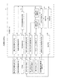
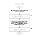
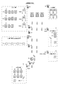
以下、図面を参照して、本発明の実施形態に係る自動搬送システムを説明する。図1〜図3は本発明の実施形態に係る自動搬送システムを説明するもので、図1は機能ブロック図、図2は自動搬送システムの運用手順を示すフローチャート、図3は搬送対象物の搬送方法を示す説明図である。 An automatic carrying system according to an embodiment of the present invention will be described below with reference to the drawings. 1 to 3 are diagrams for explaining an automatic carrying system according to an embodiment of the present invention, FIG. 1 is a functional block diagram, FIG. 2 is a flowchart showing an operating procedure of the automatic carrying system, and FIG. It is explanatory drawing which shows a method.
<自動搬送システムの概要>
本発明の実施形態に係る自動搬送システムは、図1に示すように、搬送対象物情報記憶手段10と、搬送制御情報記憶手段20と、自動搬送手段30とを基本的な構成要素としている。搬送対象物情報記憶手段10は、搬送対象物50(例えば、資機材または資機材を積載した台車やパレット)に取り付けられ、あるいは搬送対象物50の荷取り場に設置されている。
<Outline of automatic transport system>
As shown in FIG. 1, the automatic transport system according to the embodiment of the present invention has a transport object
<搬送対象物情報記憶手段>
搬送対象物情報記憶手段10は、搬送対象物50の識別情報及び搬送目的地情報を記憶した手段であり、荷取り時に当該搬送対象物50の個別情報(種類等)及び搬送目的地情報を取得することができる。
<Transport target information storage means>
The transport object information storage means 10 is a means for storing the identification information of the
なお、搬送対象物50の識別情報は、少なくとも資機材の種類を識別するための情報であればよいが、さらに、各搬送対象物50を一意に識別することが可能な情報を含んでいることが好ましく、これにより、各搬送対象物50の搬入から荷置き及び設置に関するまでの情報を総合的に管理することができる。
It should be noted that the identification information of the
自動搬送手段30は、搬送対象物50の自動搬送を行うための手段であり、例えば、無人搬送車/AGV(Automatic Guided Vehicle)からなる。詳細は後述するが、自動搬送手段30は、周囲に存在する各種の情報記憶手段から情報を取得するための手段と、自動搬送手段30を自律走行させるための手段(移動手段90、駆動手段91、自律走行制御手段37等)を備えている。
The
搬送制御情報記憶手段20は、少なくとも、搬送対象物50の荷取り場及び荷置き場に設置されており、搬送対象物50の搬送制御情報を記憶した手段である。この搬送制御情報記憶手段20は、例えば、二次元コードを印刷した印刷物(紙)、二次元コードを表示した電子ペーパーやタブレット端末、二次元コードを投影表示した投影画像、あるいは上述した二次元コードと同一の情報信号を発生する信号発生器からなる。また、搬送対象物50の搬送経路の適宜位置に搬送制御情報記憶手段20を設置して、搬送対象物50の搬送制御を行ってもよい。
The transport control
本発明の実施形態に係る自動搬送システムを構成する各手段は、それぞれの機能を発揮する機器と、コンピュータ及びこれにインストールされたプログラムにより構成される。なお、コンピュータ及びこれにインストールされたプログラムとは、パーソナルコンピュータ、マイクロコンピュータ、PLC等の演算機能を有する機器及びこれらにインストールされたプログラムを含む広い概念である。 Each unit that constitutes the automatic transport system according to the embodiment of the present invention is configured by a device that exhibits each function, a computer, and a program installed in the computer. It should be noted that the computer and the program installed in the computer are broad concepts including a device having an arithmetic function such as a personal computer, a microcomputer, and a PLC, and a program installed in these.
また、図示しないが、各手段は通信手段(通信制御手段を含む)を備えており、相互にデータ通信可能となっている。データ通信は、基本的には無線通信により行われるが、有線通信を用いてもよいし、あるいはこれらを複合して利用してもよい。また、通信方式もどのような方式であってもよい。一般的に、同一の機器内におけるデータ通信は通信ケーブルを用いた有線通信により実施され、離隔した機器間のデータ通信は無線通信により実施される。 Further, although not shown, each unit includes a communication unit (including a communication control unit) so that data can be communicated with each other. Data communication is basically performed by wireless communication, but wired communication may be used or these may be used in combination. Further, the communication system may be any system. Generally, data communication in the same device is performed by wire communication using a communication cable, and data communication between separated devices is performed by wireless communication.
<搬送制御情報記憶手段>
搬送制御情報記憶手段20は、搬送対象物50の搬送方向を情報化して表現可能であるとともに、搬送制御情報取得手段32を構成する撮影手段であるデジタルカメラで撮影可能な記号を、搬送経路の適宜箇所に表示する記号表示手段(例えば、二次元コードを印刷した印刷物(紙)、二次元コードを表示した電子ペーパーやタブレット端末、二次元コードを投影表示した投影画像)から構成することが可能である。
<Transport control information storage means>
The transport control
搬送制御情報記憶手段20として二次元コードを印刷した紙等を使用する場合に、大きさの異なる二種類の二次元コードを同一箇所に貼り付けることが好ましい。この場合、搬送制御情報取得手段32を構成する撮影手段であるデジタルカメラの撮影画角が固定されていると、自動搬送手段30の搬送制御情報記憶手段20に対する位置が遠距離である場合には、大きなサイズの二次元コードが存在することにより、遠方からでも二次元コードを認識することができる。一方、自動搬送手段30の搬送制御情報記憶手段20に対する位置が近距離である場合には、大きなサイズの二次元コードででは撮影画角からはみ出し認識できない可能性がある。このため、小さなサイズの二次元コードが存在することにより、近距離においても二次元コードを認識することができる。一般的には、大きさが異なる二次元コードにより表現する情報は同一であるが、遠距離から認識可能な二次元コードには概略情報を記憶させ、近距離で認識可能な二次元コードには詳細な情報を記憶させてもよい。このような態様とすることにより、遠距離から概略情報を取得できるとともに、近距離ではさらに詳細な情報を取得することができる。
When a paper or the like on which a two-dimensional code is printed is used as the transport control
また、搬送制御情報記憶手段20は、搬送制御情報を発信する信号発生器であってもよい。搬送制御情報記憶手段20として、二次元コードを印刷した紙、二次元コードを表示する電子ペーパーやタブレット端末、二次元コードを投影する投影装置を用いた場合には、搬送対象物50の搬送現場において搬送制御情報記憶手段20を手軽に作成することができるだけではなく、汚損や破損した際にも、再作成が容易であり、搬送現場の状況に応じて臨機応変に搬送制御情報を変更することができる
Further, the transport control information storage means 20 may be a signal generator that transmits the transport control information. When a paper on which a two-dimensional code is printed, an electronic paper or a tablet terminal that displays the two-dimensional code, or a projection device that projects the two-dimensional code is used as the transportation control
<自動搬送手段>
自動搬送手段30は、搬送対象物50を所望の位置にまで走行させるための手段である。この自動搬送手段30は、本体部に設けた移動手段90と、移動手段90を駆動するための駆動手段91と、搬送対象物50を保持するための保持手段80と、自律走行制御手段37とを備えている。
<Automatic transport means>
The
また、自動搬送手段30は、搬送対象物情報取得手段31、搬送制御情報取得手段32、障害物検知手段33、障害物回避経路決定手段33a、搬送対象物相対位置検出手段34、既荷置き位置情報取得手段35、空きスペース情報取得手段36、自動荷取り制御手段38a、荷置き位置決定手段38b、電源装置設置位置情報取得手段39を備えている。
Further, the automatic carrying means 30, the carrying target object
<駆動手段>
駆動手段91は、移動手段90を駆動するためのモータ等からなる。例えば、移動手段90が車輪の場合には、駆動手段91は車輪を駆動するためのモータからなる。この場合、移動手段90として機能する車輪の他に、駆動力が伝達されない車輪を備えていてもよい。また、移動手段90の数は限定されないが、すべての車輪を移動手段90としてもよいし、一部の車輪を移動手段90としてもよい。
<Driving means>
The driving means 91 is composed of a motor or the like for driving the moving
具体的には、移動手段90は、シャフトに接続されたホイールの円周上に回転可能に支持されたローラ(樽型車輪)を有しており、ホイールの回転方向(基準方向に対して相対的に前後)と、ローラの回転方向(基準方向に対して相対的に左右)へ動くことができる。また、移動手段90及び駆動手段91として、クローラや多足歩行(例えば、4足歩行)する歩行装置を用いてもよい。
Specifically, the moving
<保持手段>
保持手段80は、搬送対象物50を保持するための手段であり、自動搬送手段30の態様に応じて、種々の態様とすることができる。例えば、搬送対象物50を載置する装置、搬送対象物50を吊り下げる装置、搬送対象物50を牽引する装置が保持手段80となる。
<Holding means>
The holding means 80 is a means for holding the
また、搬送対象物50をパレット上に載置したり、車輪付きのカゴに収容したりすることにより、パレットやカゴを保持して搬送を行ってもよい。車輪付きのカゴやパレットを使用する場合には、門形の本体部を有する自動搬送手段30を使用する。詳細には図示しないが、このような態様の自動搬送手段30は、本体部の下部に移動手段90を設け、本体部の上部に搬送対象物情報取得手段31及び搬送制御情報取得手段32として機能するデジタルカメラを取り付け、本体部の前面に、障害物検知手段33として機能する赤外線センサと、搬送対象物相対位置検出手段34として機能するLRF(測域センサ)を取り付ける。
Further, the
さらに、門形の本体部の側面に、障害物(壁等)に接触した際に、自動搬送手段30の移動を停止させるための移動停止スイッチや、障害物への接触衝撃を緩和するための衝撃緩和装置(複数のローラ及び各ローラを本体部から外方へ向かって突出させるように付勢力を付与するバネ等)を設けてもよい。このような構成では、自動搬送手段30の側面が障害物(壁等)に接触すると、まず初めに衝撃緩和装置により接触衝撃を緩和し、さらに衝撃緩和装置に対して押圧が加わると移動停止スイッチが作動して、自動搬送手段30の移動が停止する。
Further, a movement stop switch for stopping the movement of the automatic carrying means 30 when an obstacle (a wall or the like) is brought into contact with the side surface of the gate-shaped main body portion, and for mitigating a contact impact on the obstacle. An impact absorbing device (a plurality of rollers and a spring or the like that applies a biasing force to the rollers so as to project them outward from the main body) may be provided. In such a configuration, when the side surface of the automatic transporting
また、パレットや車輪付きのカゴの両側面にロック棒を取り付けるとともに、自動搬送手段30の本体部には、ロック棒に対向する位置に、ロック棒に係合してロック可能なロック機構を設ける。ロック機構は、通常は開状態となっており、ロック棒に押し当たると閉状態となって、自動搬送手段30の本体部とパレットや車輪付きのカゴとを一体に連結することができる。なお、ロック機構のロックは、自動搬送手段30が荷置き位置に到着したことを認識すると自動的に解除されるように構成する。
Further, lock bars are attached to both side surfaces of a pallet or a basket with wheels, and a lock mechanism capable of engaging with and locking the lock bars is provided at a position facing the lock bar on the main body of the automatic transporting
<自律走行制御手段>
自律走行制御手段37は、取得した搬送対象物50の識別情報及び搬送目的地情報に従って、自動搬送手段30を自律走行させるための手段であり、取得した搬送対象物50の識別情報、搬送目的地情報、障害物情報等に基づいて駆動手段91を制御し、自動搬送手段30を目的の位置まで走行させる。
<Autonomous traveling control means>
The autonomous
<搬送対象物情報取得手段>
搬送対象物情報取得手段31は、搬送対象物情報記憶手段10に記憶された搬送対象物50の識別情報及び搬送目的地情報を取得するための手段であり、例えば、撮影手段であるデジタルカメラ及びその付帯装置と、マイクロコンピュータ及びこれにインストールされたプログラムにより構成する。また、搬送対象物情報記憶手段10が信号発生器である場合に、搬送対象物情報取得手段31は信号を受信するための信号受信器(受信手段)により構成する。
<Transportation object information acquisition means>
The transport target object
上述したように、搬送対象物情報記憶手段10は、搬送対象物50に取り付けられた二次元コード等からなり、デジタルカメラにより二次元コードを撮影して解析することにより、当該搬送対象物50の識別情報及び搬送目的地情報を取得することができる。搬送目的地は搬送対象物50の荷置き場であるが、1個の搬送対象物50を荷置きするだけではなく、複数個の搬送対象物50を荷置き可能なエリア(搬送目的地エリア70)とすることが可能である。この場合、搬送対象物50の識別情報は荷置き場のエリア情報(搬送目的地エリア情報)を含んでいることになる。
As described above, the transport target object
<搬送制御情報取得手段>
搬送制御情報取得手段32は、搬送制御情報記憶手段20に記憶された搬送制御情報を取得するための手段であり、例えば、撮影手段であるデジタルカメラ及びその付帯装置と、マイクロコンピュータ及びこれにインストールされたプログラムにより構成する。また、搬送制御情報記憶手段20が信号発生器である場合に、搬送制御情報取得手段32は信号を受信するための信号受信器(受信手段)により構成する。
<Transport control information acquisition means>
The transfer control
上述したように、搬送制御情報は、搬送経路の適宜箇所に設置(例えば、貼付)された二次元コードを印刷した紙、二次元コードを表示した電子ペーパーやタブレット端末、二次元コードを投影表示した投影画像等からなり、搬送制御情報取得手段32を構成する撮影手段であるデジタルカメラにより二次元コードを撮影して解析することにより、搬送対象物50の搬送制御情報(例えば、自動搬送手段30の通過情報)を取得することができる。
As described above, the transport control information includes the paper printed with the two-dimensional code installed (for example, attached) at an appropriate position on the transport route, the electronic paper or tablet terminal displaying the two-dimensional code, and the two-dimensional code projected and displayed. The two-dimensional code is captured by a digital camera, which is an image capturing unit that constitutes the transport control
搬送対象物情報取得手段31と搬送制御情報取得手段32は、同一の機器により構成することができる。すなわち、搬送対象物情報取得手段31と搬送制御情報取得手段32は、自動搬送手段30の走行方向に向かって前方及び左右側方に取り付けたデジタルカメラと、撮影データを解析するプログラム及びこれをインストールしたマイクロコンピュータにより構成することができる。この場合、デジタルカメラにパン・チルト機構を設けて、デジタルカメラの撮影方向を変化させることにより、撮影対象となる二次元コード等を確実に撮影することができる。
The conveyance object
さらに、搬送対象物情報取得手段31と搬送制御情報取得手段32として、水平方向に回転可能なデジタルカメラを用いることにより、デジタルカメラの台数を減らすことができる。また、各情報記憶手段が信号発生器の場合には、搬送対象物情報取得手段31と搬送制御情報取得手段32を信号受信器により構成してもよい。 Furthermore, the number of digital cameras can be reduced by using digital cameras that can be rotated in the horizontal direction as the conveyance object information acquisition means 31 and the conveyance control information acquisition means 32. When each information storage means is a signal generator, the conveyance object information acquisition means 31 and the conveyance control information acquisition means 32 may be constituted by a signal receiver.
また、後述する障害物検知手段33、搬送対象物相対位置検出手段34、既荷置き位置情報取得手段35のように、デジタルカメラ、赤外線センサ、LRF(測域センサ)及びこれらの付帯装置により構成する手段についても、すべてを同一の機器により構成してもよいし、それぞれ別個の機器により構成してもよい。なお、デジタルカメラとは、撮像レンズ、合焦装置、撮像素子、映像データを含むデータを送受信可能な送受信デバイス等を備えたカメラのことである(以下に説明するデジタルカメラにより構成される各手段においても同様)。 Further, like an obstacle detection means 33, a conveyed object relative position detection means 34, and an already-loaded position information acquisition means 35 which will be described later, it is configured by a digital camera, an infrared sensor, an LRF (range-finding sensor), and auxiliary devices thereof. Regarding the means for doing so, they may all be configured by the same device or may be configured by separate devices. The digital camera is a camera including an image pickup lens, a focusing device, an image pickup device, a transmission/reception device capable of transmitting/receiving data including video data (each unit configured by the digital camera described below. Also in).
搬送制御情報取得手段32として機能するデジタルカメラは、搬送制御情報記憶手段20である二次元コードを撮影しながら、自動搬送手段30とともに移動する。この際、撮影した二次元コードの映像データを解析することにより、自動搬送手段30の搬送制御情報を取得するだけではなく、自動搬送手段30と二次元コードとの距離、自動搬送手段30が二次元コードに対向する角度に関する情報等を取得し、自己位置推定を行う。
The digital camera functioning as the transfer control
<障害物検知手段>
障害物検知手段33は、搬送経路に存在する障害物40を検知するための手段であり、例えば、赤外線センサ及び付帯装置と、マイクロコンピュータ及びこれにインストールされたプログラムにより構成する。また、障害物検知手段33として、デジタルカメラ及び付帯装置を用いてもよい。障害物検知手段33を赤外線センサにより構成した場合には、赤外線を用いたセンシングにより、障害物40を検知することができる。また、障害物検知手段33をデジタルカメラ及びその付帯装置により構成した場合には、自動搬送手段30が走行中に、デジタルカメラにより自動搬送手段30の前方の映像を撮影し、映像データを解析することにより、障害物40を検知することができる。
<Obstacle detection means>
The
<障害物回避経路決定手段>
障害物回避経路決定手段33aは、障害物40を検知した場合に、当該障害物40を避けて、取得した搬送対象物50の識別情報及び搬送目的地情報に合致した経路を決定するための手段であり、例えば、マイクロコンピュータ及びこれにインストールされたプログラムにより構成する。障害物回避経路決定手段33aは、障害物検知手段33で自動搬送手段30の進行方向に障害物40を検知した場合に、当該障害物40を避けて、自動搬送手段30が保持している搬送対象物50の識別情報及び搬送目的地情報に合致した経路となるように迂回経路を決定する。迂回経路により障害物40を避けた後は、自動搬送手段30が保持している搬送対象物50の識別情報及び搬送目的地情報に基づいて、自動搬送手段30を走行させる。
<Obstacle avoidance route determination means>
The obstacle avoiding route determination means 33a, when detecting the
<搬送対象物相対位置検出手段>
搬送対象物相対位置検出手段34は、自動搬送手段30と搬送対象物50との相対位置を検出するための手段であり、例えば、LRF(測域センサ)及び付帯装置やデジタルカメラ及び付帯装置と、マイクロコンピュータ及びこれにインストールされたプログラムにより構成する。搬送対象物相対位置検出手段34は、LRF(測域センサ)やデジタルカメラにより自動搬送手段30の前方に存在する搬送対象物50を認識し、認識データを解析することにより、自動搬送手段30と搬送対象物50との相対位置を検出することができる。これにより、荷取りを行う際に、搬送対象物50に対する自動搬送手段30の相対位置情報を得ることができる。
<Transfer target relative position detecting means>
The conveyance object relative position detection means 34 is a means for detecting the relative position between the automatic conveyance means 30 and the
<自動荷取り制御手段>
自動荷取り制御手段38aは、取得した自動搬送手段30と搬送対象物50との相対位置に基づいて、搬送対象物50の設置状況に関わらず、自動搬送手段30が当該搬送対象物50を確実に荷取り可能な位置となるように制御するための手段であり、例えば、マイクロコンピュータにより構成する。すなわち、搬送対象物相対位置検出手段34により搬送対象物50と自動搬送手段30との相対位置が検出されると、相対位置情報を解析して搬送対象物50に対して自動搬送手段30が荷取りできる位置となるように、自動搬送手段30(駆動手段91)を制御して自動搬送手段30の向きを調整する。
<Automatic pickup control means>
The automatic
搬送対象物50は、必ずしも正確に整列して置かれているとは限らず、本来置かれるべき位置からずれていることがある。すなわち、搬送対象物50を正確に整列させるには、きめ細かな作業が必要となり、正確さを追求すると搬送作業に時間が掛かりすぎるおそれがある。このため、搬送作業を容易なものとするために、搬送対象物50の整列精度にはある程度の許容度がある。そして、荷取りを行う場合に、搬送対象物50に対して自動搬送手段30が安全かつ自律的に荷取りできる位置となるようにしないと、荷取りの際に搬送対象物50に損傷を与えたり、最悪の場合には、荷取りを行うことができなかったりする。そこで、本実施形態では、自動荷取り制御手段38aにより、自動搬送手段30が搬送対象物50を安全に荷取りできる位置となるように制御することにより、容易かつ正確で安全な荷取り作業を行うことができるようにしている。
The objects to be conveyed 50 are not always placed in a precise alignment, and may be displaced from the position where they should be placed. That is, in order to accurately align the
さらに詳細に説明すると、搬送対象物50(資機材)に設置した搬送対象物情報記憶手段10(二次元コード)をデジタルカメラで確認して資機材の存在及びおおまかな位置を把握する。その後、LRF(測域センサ)で資機材の形状をスキャンし、保持進入位置を確定し、保持手段80により搬送対象物50(資機材)を保持する。なお、搬送対象物情報記憶手段10として機能する二次元コードに記憶された情報は、「搬送対象物50(資機材)は何か」という情報と、「搬送対象物50(資機材)の搬送先」に関する情報の2種類であるが、本実施形態において、搬送対象物情報記憶手段10(二次元コード)は、搬送対象物50(資機材)の存在(あるかないか)と大まかな位置を把握するための役割も有している。
More specifically, the existence and rough position of the material and equipment are grasped by confirming the object-to-be-transported information storage means 10 (two-dimensional code) installed on the material to be transported 50 (material and equipment) with a digital camera. After that, the shape of the material and equipment is scanned by the LRF (range-finding sensor), the holding approach position is determined, and the object to be conveyed 50 (material and equipment) is held by the holding means 80. The information stored in the two-dimensional code that functions as the transport target
<既荷置き位置情報取得手段>
既荷置き位置情報取得手段35は、取得した搬送対象物50の識別情報及び搬送目的地情報に対応する搬送目的地エリア70内において既に荷置きされている搬送対象物60の位置情報を取得するための手段であり、LRF(測域センサ)及び付帯装置やデジタルカメラ及び付帯装置と、マイクロコンピュータ及びこれにインストールされたプログラムにより構成する。自動搬送手段30が搬送目的地エリア70に到着すると、既荷置き位置情報取得手段35であるLRF(測域センサ)により搬送目的地エリア70内をスキャニングし、あるいはデジタルカメラにより搬送目的地エリア70内を撮影し、取得したデータを解析することにより、既に荷置きされている搬送対象物60の位置情報を取得する。これにより、搬送目的地エリア70のどの位置に、既に搬送対象物60が置かれているかを認識することができる。
<Means to acquire information on the location of already loaded items>
The already-loaded position information acquisition means 35 acquires the position information of the
<空きスペース情報取得手段>
空きスペース情報取得手段36は、既に荷置きされている搬送対象物60の位置情報に基づいて、搬送対象物50を荷置き可能な空きスペースの位置情報を取得するための手段であり、例えば、マイクロコンピュータにより構成する。空きスペース情報取得手段36は、既荷置き位置情報取得手段35の機能により取得した搬送対象物(既に荷置きされた搬送対象物60)の位置情報と、搬送目的地エリア70の情報(面積等の情報)に基づき空きスペースを解析して、空きスペース情報を取得する。
<Free space information acquisition method>
The empty space
<荷置き位置決定手段>
荷置き位置決定手段38bは、空きスペース内において新たな搬送対象物50を荷置きする位置を決定するための手段であり、例えば、マイクロコンピュータにより構成する。荷置き位置決定手段38bは、搬送対象物50の搬送目的地である搬送目的地エリア70において、空きスペース情報取得手段36の機能により取得した空きスペース情報に基づき自動搬送手段30(駆動手段91)を制御して、搬送目的地エリア70内の空きスペースに搬送対象物50を荷置きする。
<Means for determining loading position>
The loading
<充電用電源装置>
本実施形態の自動搬送手段30の駆動手段91は電動モータにより構成されているため、必要に応じて充電池を充電する必要がある。そこで、本実施形態に係る自動搬送システムは、図3に示すように、充電用電源装置110を備えている。この充電用電源装置110は、自動搬送システムを適用する建設現場等の適宜位置に設置する。
<Power supply for charging>
Since the driving means 91 of the automatic carrying means 30 of this embodiment is composed of an electric motor, it is necessary to charge the rechargeable battery as needed. Therefore, as shown in FIG. 3, the automatic transport system according to this embodiment includes a charging
本実施形態では、充電用電源装置110の設置場所に、その旨を示す電源装置設置位置情報記憶手段100を設置しておく。電源装置設置位置情報記憶手段100は、搬送対象物情報記憶手段10や搬送制御情報記憶手段20と同様に、二次元コードを印刷した印刷物(紙)、電子ペーパー、タブレット端末、投影画像、信号発生器により構成することができる。したがって、自動搬送手段30が充電用電源装置110の設置場所を認識するには、搬送対象物情報取得手段31や搬送制御情報取得手段32と同様の構成からなる電源装置設置位置情報取得手段39を用いればよい。
In the present embodiment, the power supply device installation position information storage means 100 indicating that is installed in the installation place of the charging
自動搬送手段30に搭載された充電池の充電が必要となると、自律走行制御手段37の制御により駆動手段91を制御し、自動搬送手段30を充電用電源装置110の設置位置まで走行させる。そして、充電池の充電を行い、自動搬送手段30が使用可能な状態となったら、自動搬送手段30の使用を開始する。
When the rechargeable battery mounted on the automatic transporting
<自動搬送システムの運用>
次に、上述した自動搬送システムの運用について説明する。図2は、自動搬送システム運用のフローチャートである。なお、以下の説明において具体的な情報を示しているが、これらは一例であり、適宜変更して実施することができる。
<Operation of automatic transport system>
Next, operation of the above-described automatic transport system will be described. FIG. 2 is a flowchart of the operation of the automatic transport system. It should be noted that although specific information is shown in the following description, these are examples and can be appropriately modified and implemented.
自動搬送システムを運用するには、図2に示すように、自動搬送システムを構成するコンピュータシステム(パソコン)に、搬送対象物50を積載する台車の数及び台車の行き先に関するデータを入力する(S1)。このデータ入力工程は、搬送目的地(荷置き場)が複数箇所存在する場合に搬送所要時間を算出するための工程である。搬送所要時間を算出するためには、荷置き場「G01」に台車○台搬送、荷置き場「G02」に台車△台搬送、荷置き場「G03」に台車×台搬送という情報が必要となる。 In order to operate the automatic transport system, as shown in FIG. 2, data relating to the number of trucks on which the objects to be transported 50 are loaded and destinations of the trucks are input to a computer system (personal computer) constituting the automatic transport system (S1). ). This data input step is a step for calculating a required transportation time when there are a plurality of transportation destinations (load storage areas). In order to calculate the required transportation time, it is necessary to have information such that the cargo storage area "G01" has a carriage of "○", the cargo storage area "G02" has a carriage of "△", and the cargo storage area "G03" has a carriage of "carry".
また、搬送エリア内の適宜位置に充電用電源装置110を配置し、充電用電源装置110の配置位置(設置場所)に電源装置設置位置情報記憶手段100を設置する(S2)。電源装置設置位置情報記憶手段100に記憶される情報は、「PEND」である。
Further, the charging
搬送対象物50を積載する台車に、搬送対象物情報記憶手段10を取り付けるとともに、荷取り場、荷置き場、台車、自動搬送手段30の待機場所、搬送経路に、それぞれ搬送制御情報記憶手段20を設置する(S3)。搬送対象物情報記憶手段10には、搬送対象物50の識別情報(資機材情報)及び搬送目的地情報(搬送先情報)として、それぞれ「A1/M01」、「A2/M02」、「A3/M03」が記憶されている。「A1」、「A2」、「A3」は資機材情報であり、「M01」、「M02」、「M03」は搬送先情報である。この場合、搬送対象物情報記憶手段10は搬送制御情報記憶手段20の機能を兼ね備えている。荷取り場に設置する搬送制御情報記憶手段20には、荷取り場であることを示す搬送制御情報が記憶されている。この荷取り場であることを示す搬送制御情報は、「S01」、「S02」、「S03」・・・である。
The transport object information storage means 10 is attached to the trolley on which the
荷置き場に設置する搬送制御情報記憶手段20には、荷置き場であることを示す搬送制御情報が記憶されている。この荷置き場であることを示す搬送制御情報は、「G01」、「G02」、「G03」・・・である。自動搬送手段30の待機場所に設置する搬送制御情報記憶手段20には、自動搬送手段30の待機場所であることを示す搬送制御情報が記憶されている。この自動搬送手段30の待機場所であることを示す搬送制御情報は、「QEND」である。
The transport control
搬送経路に設置する搬送制御情報記憶手段20には、順を追った搬送経路に関する搬送制御情報が記憶されている。一般的な搬送経路には5m程度の間隔で搬送制御情報記憶手段20を設置し、次の搬送制御情報記憶手段20を確認することができない曲がり角等には2m程度の間隔で搬送制御情報記憶手段20を設置する。この搬送経路に設置する搬送制御情報記憶手段20に記憶された搬送制御情報は、エレベーターまでの搬送制御情報として「E01」、「E02」、「E03」・・・(図示せず)が記憶され、N階における搬送制御情報として「N01」、「N02」、「N03」・・・が記憶され、荷取り場から充電用電源装置110の設置位置までの搬送制御情報として「P01」、「P02」、「P03」・・・が記憶されている。
The transport control
上述した工程が終了したら、自動搬送手段30に電源を入れて(S4)、自動搬送システムの運用を開始する。なお、自動搬送システムの運用を終了するには、自動搬送手段30の電源を切ればよい。自動搬送手段30に電源を入れるとは、コンピュータシステム(パソコン)を操作してスタートボタンを押すことであり、自動搬送手段30の電源を切るとは、コンピュータシステム(パソコン)を操作してストップボタンを押すことである。
When the above steps are completed, the automatic carrying means 30 is turned on (S4) and the operation of the automatic carrying system is started. To end the operation of the automatic transfer system, the automatic transfer means 30 may be turned off. Turning on the power of the automatic transporting
<自動搬送方法の具体例>
次に、上述した自動搬送システムを用いて、搬送対象物50を搬送する方法について説明する。図3は、自動搬送システムを用いて、自動搬送手段30が荷取り場で荷取り作業を行い、指定された搬送目的地(荷置き場)で荷置き作業を行う一連の工程を説明するための説明図である。また、自動搬送システムは、上述したすべての機能手段を備えているものとして説明を行うが、実運用においては一部の機能手段を省略してもよいし、他の機能手段を備えていてもよい。
<Specific example of automatic transportation method>
Next, a method of transporting the
本実施形態の自動搬送手段30を用いて搬送対象物50を荷取り場から荷置き場まで搬送するには、予め、搬送対象物(資機材または資機材を積載した台車やパレット)50に、あるいは搬送対象物50の荷取り場に、当該搬送対象物50を識別するための識別情報及び搬送目的地情報を記憶した搬送対象物情報記憶手段10を設置しておく。具体的には、搬送対象物(資機材または資機材を積載した台車やパレット)50に、あるいは搬送対象物50の荷取り場に、当該搬送対象物50を識別するための識別情報及び搬送目的地情報を示す二次元コードの印刷物を貼付したり、二次元コードを表示する電子ペーパーやタブレット端末を設置したりする。
In order to convey the
また、各搬送対象物50の荷取り場には当該搬送対象物50の荷取り場である旨の情報を記憶した搬送制御情報記憶手段20(標識S01)を設置し、各搬送対象物50の荷置き場には各搬送対象物50の荷置き場である旨の情報を記憶した搬送制御情報記憶手段20(標識G01、G02、G03)を設置しておく。さらに、各搬送対象物50の搬送経路の適宜位置に、各搬送対象物の通過に関する情報を記憶した搬送制御情報記憶手段20(標識N01、N02、N03)を設置しておく。各搬送対象物50(あるいは各搬送対象物50を積載した台車やパレット)に取り付けた搬送対象物情報記憶手段10に記憶された搬送先情報であるM01、M02、M03と、荷置き場にそれぞれ設置された標識G01、G02、G03が表す荷取り場の位置情報とは同一である。すなわち、荷取り場の位置情報として、M01=G01、M02=G02、M03=G03となっている。
In addition, a transportation control information storage means 20 (mark S01) that stores information indicating that the
以下、建設現場における資機材(搬送対象物50)の搬送について説明を行う。荷取り場には、種々の資機材が運び込まれてくる。各資機材は、自動搬送手段30により保持可能とするため、台車上に載置されたり、カゴに収納されたりしている。また、各資機材自体あるいは荷取り場の適宜箇所には、当該資機材(搬送対象物50)の識別情報及び搬送目的地情報を認識させるための搬送対象物情報記憶手段10(例えば、二次元コードを印刷した印刷物、二次元コードを表示する電子ペーパーやタブレット端末)を設置する。具体的には、荷取り場には、資機材A1、A2、A3が運び込まれており、各資機材自体あるいは各資機材の荷取り位置には、それぞれ識別情報(A1、A2、A3)及び搬送目的地情報(M01、M02、M03)を示す搬送対象物情報記憶手段10が設置されている。 Hereinafter, the transportation of the materials and equipment (the transportation target object 50) at the construction site will be described. Various materials and equipment are brought into the unloading area. Since each of the materials and equipment can be held by the automatic carrying means 30, they are placed on a trolley or stored in a basket. In addition, the transport object information storage means 10 (for example, two-dimensional) for recognizing the identification information of the transport equipment (transport target 50) and the transport destination information is provided at each material itself or at an appropriate place of the yard. Install a printed material that prints the code, electronic paper or tablet terminal that displays the two-dimensional code. Specifically, the materials and equipment A1, A2, and A3 are carried into the unloading site, and the identification information (A1, A2, and A3) and the respective materials and equipment itself or the unloading position of the materials and equipment are provided. A transport object information storage means 10 indicating transport destination information (M01, M02, M03) is installed.
自動搬送手段30が搬送制御情報取得手段32の機能により荷取り場であることを認識すると、荷取り作業を行う(保持手段33により資機材を保持する)。そして、搬送対象物情報取得手段31の機能により、当該搬送対象物50の識別情報及び搬送目的地情報を取得する。すなわち、荷取りする資機材が、A1、A2、A3のいずれであるかを認識するとともに、資機材A1、A2、A3の荷置き場がどこであるかを認識する。以下、搬送対象物情報記憶手段10及び搬送制御情報記憶手段20を標識S01、M01〜M03、N01〜N03、P01、PENDとして説明する。
When the automatic carrying means 30 recognizes that it is a yard by the function of the carrying control
資機材40を保持するための自動搬送手段30が作業領域内を走行し、搬送制御情報取得手段32の機能により荷取り場であることを示す標識S01を認識すると、資機材A1、A2、A3の荷取り作業を開始する。この際、搬送対象物情報取得手段31の機能により、荷取りする資機材がA1、A2、A3のいずれであるかを認識するとともに、搬送先情報であるM01〜M03に基づいて各資機材A1、A2、A3の荷置き場がどこであるかを認識する。上述したように、搬送先情報であるM01、M02、M03が表す搬送先情報(荷置き場の位置情報)と、荷取り場にそれぞれ設置された標識G01、G02、G03が表す情報は同一となっている。
When the automatic transporting
資機材A1の荷置き場(1)には、その旨を示す標識G01が設置されており、資機材A2の荷置き場(2)には、その旨を示す標識G02が設置されており、資機材A3の荷置き場(3)には、その旨を示す標識G03が設置されている。また、資機材の搬送経路には、資機材の通過地点を示す標識N01、N02、N03が設置されている。標識N01は、資機材A1、A2、A3を通過させる情報を示す搬送制御情報記憶手段20であり、標識N02は、資機材A1、A2を通過させる情報を示す搬送制御情報記憶手段20であり、標識N03は、資機材A1を通過させる情報を示す搬送制御情報記憶手段20である。
A sign G01 indicating that effect is installed in the cargo storage area (1) of the material A1 and a sign G02 indicating that effect is installed in the cargo storage area (2) of the material A2. A sign G03 indicating that effect is installed at the loading place (3) of A3. Further, signs N01, N02, N03 indicating the passage points of the materials and equipment are installed on the transportation route of the materials and equipment. The sign N01 is a transport control information storage means 20 indicating information for passing the materials A1, A2, A3, and the sign N02 is a transport control information storage means 20 indicating information for passing the materials A1, A2. The mark N03 is a transport control
また、充電用電源装置110の設置位置(設置場所)には、その旨を示す標識PENDが設置されており、荷取り場から充電用電源装置110の設置位置(設置場所)までの経路には、その旨を示す標識P01が設置されている。
In addition, a sign PEND indicating that is installed at the installation position (installation site) of the charging
なお、荷取り場では、搬送対象物相対位置検出手段34であるLRF(測域センサ)により自動搬送手段30の前方に存在する搬送対象物50をスキャニングし、取得したデータを解析することにより、自動搬送手段30と搬送対象物50との相対位置を検出する。そして、自動荷取り制御手段38aの機能により、搬送対象物50に対して自動搬送手段30が自律的に荷取りできる位置となるように、自動搬送手段30(駆動手段91)を制御して自動搬送手段30の向きを調整する。
It should be noted that, at the unloading site, the
資機材A1を保持した自動搬送手段B1が作業領域内を走行して、標識N01、N02、N03を認識した場合には、各標識N01、N02、N03の設置位置を通過する。また、資機材A1を保持した自動搬送手段B1が作業領域内を走行して、標識G02、G03を認識した場合には、資機材A1に関する情報は含まれていないため、他の標識を認識できるまで走行を継続する。そして、資機材A1を保持した自動搬送手段B1が作業領域内を走行して、標識G01を認識すると、資機材A1の荷置き場であるため、荷置き場内の適宜位置に荷置きを行う。 When the automatic transporting means B1 holding the material A1 travels in the work area and recognizes the signs N01, N02, N03, it passes through the installation positions of the respective signs N01, N02, N03. Further, when the automatic transporting means B1 holding the material A1 travels in the work area and recognizes the signs G02 and G03, the other information can be recognized because the information regarding the material A1 is not included. Continue running until. When the automatic transporting means B1 holding the material A1 travels in the work area and recognizes the sign G01, it is the loading place for the material A1 and therefore the loading is performed at an appropriate position in the loading place.
この際、荷置き場の空きスペースに荷置きを行うような制御を行うことが好ましい。具体的には、既荷置き位置情報取得手段35であるLRF(測域センサ)により搬送目的地エリア70をスキャニングし、取得したデータを解析することにより、既に荷置きされている搬送対象物60の位置情報を取得する。そして、空きスペース情報取得手段36の機能により、既に荷置きされた搬送対象物60の位置情報と、搬送目的地エリア70の情報(面積等の情報)に基づき空きスペースを解析して、空きスペース情報を取得する。空きスペース情報を取得したら、荷置き位置決定手段38bの機能により、自動搬送手段B1を制御して、搬送目的地エリア70である空きスペースに新たな資機材A1を荷置きする。資機材A2及び資機材A3についても、同様の制御を行うことにより、空きスペースに荷置きを行うことができる。
At this time, it is preferable to perform control such that the cargo is placed in an empty space in the cargo storage area. Specifically, the
また、搬送経路の途中に障害物(仮置きされた資機材等)40が存在した場合には、障害物検知手段33により障害物40を検知する。そして、障害物回避経路決定手段33aの機能により、当該障害物40を避けて、自動搬送手段B1が保持している資機材A1の識別情報及び搬送目的地情報に合致した経路となるように迂回経路を決定する。迂回経路により障害物40を避けた後は、自動搬送手段B1が保持している資機材A1の識別情報及び搬送目的地情報に基づいて、自動搬送手段B1を走行させる。資機材A2及び資機材A3についても、同様の制御を行うことにより、障害物40を避けて自動搬送手段B2、B3を走行させることができる。
Further, when an obstacle (temporarily placed materials and equipment) 40 exists in the middle of the transportation route, the
資機材A2を保持した自動搬送手段B2が作業領域内を走行して、標識N01、N02を認識した場合には、各標識N01、N02の設置位置を通過する。また、資機材A2を保持した自動搬送手段B2が作業領域内を走行して、標識G01、G03、N03を認識した場合には、資機材A2に関する情報は含まれていないため、他の標識を認識できるまで走行を継続する。そして、資機材A2を保持した自動搬送手段B2が作業領域内を走行して、標識G02を認識すると、資機材A2の荷置き場であるため、荷置き場内の適宜位置に荷置きを行う。 When the automatic transporting means B2 holding the material A2 travels in the work area and recognizes the signs N01 and N02, it passes through the installation positions of the signs N01 and N02. Further, when the automatic transporting means B2 holding the material A2 travels in the work area and recognizes the signs G01, G03, N03, since the information regarding the material A2 is not included, another sign is displayed. Continue driving until you can recognize it. When the automatic transporting means B2 holding the material A2 travels in the work area and recognizes the sign G02, it is the loading place for the material A2, and therefore the loading is performed at an appropriate position in the loading place.
資機材A3を保持した自動搬送手段B3が作業領域内を走行して、標識N01を認識した場合には、標識N01の設置位置を通過する。また、資機材A3を保持した自動搬送手段B3が作業領域内を走行して、標識G01、G02、N02、N03を認識した場合には、資機材A3に関する情報は含まれていないため、他の標識を認識できるまで走行を継続する。そして、資機材A3を保持した自動搬送手段B3が作業領域内を走行して、標識G03を認識すると、資機材A3の荷置き場であるため、荷置き場内の適宜位置に荷置きを行う。 When the automatic transporting means B3 holding the material A3 travels in the work area and recognizes the sign N01, it passes through the installation position of the sign N01. In addition, when the automatic transporting means B3 holding the material A3 travels in the work area and recognizes the signs G01, G02, N02, and N03, the information regarding the material A3 is not included, and thus other information is not included. Continue driving until you recognize the sign. When the automatic transporting means B3 holding the material A3 travels in the work area and recognizes the sign G03, it is the loading place for the material A3, so that the article is placed at an appropriate position in the loading place.
このような搬送経路において、自動搬送手段B1が標識N01の認識に失敗したとしても、標識N02、標識N03、標識G01を認識できれば正確な搬送目的地まで資機材A1を搬送することができる。すなわち、たまたま標識N01の位置に作業者が居て、自動搬送手段B1が標識N01の認識に失敗すると、自動搬送手段B1はそのまま直進して標識N02まで進み、自律走行を継続する。 Even if the automatic transporting means B1 fails to recognize the marker N01 on such a transporting route, if the marker N02, the marker N03, and the marker G01 can be recognized, the material A1 can be accurately transported to the transport destination. That is, when the operator happens to be at the position of the sign N01 and the automatic transporting means B1 fails to recognize the sign N01, the automatic transporting means B1 goes straight to the sign N02 and continues autonomous traveling.
同様に、自動搬送装置B2が標識N01の認識に失敗したとしても、標識N02、標識G02を認識できれば正確な搬送目的地まで資機材A2を搬送することができる。すなわち、たまたま標識N01の位置に作業者が居て、自動搬送手段B2が標識N01の認識に失敗すると、自動搬送手段B2はそのまま直進して標識N02まで進み、自律走行を継続する。 Similarly, even if the automatic carrier B2 fails to recognize the marker N01, if the marker N02 and the marker G02 can be recognized, the material A2 can be conveyed to an accurate destination. That is, when the operator happens to be at the position of the sign N01 and the automatic transporting means B2 fails to recognize the sign N01, the automatic transporting means B2 goes straight to the sign N02 and continues autonomous traveling.
また、自動搬送装置B3が標識N01の認識に失敗して標識N02の位置まで進んでしまった場合には、標識N02には資機材A3に関する情報は含まれていないため、自動搬送手段B3は他の標識を探して走行する。例えば、自動搬送装置B3は、関連する情報を含んでいる標識N01または標識G03を認識できる位置まで走行を継続し、これらの標識を認識できると、資機材A3の荷置き場で荷置きを行うことができる。 Further, when the automatic carrier B3 fails to recognize the marker N01 and moves to the position of the marker N02, the marker N02 does not include information on the equipment A3, and therefore the automatic carrier B3 is different. Look for the sign and drive. For example, the automatic carrier B3 continues traveling to a position where it can recognize the sign N01 or the sign G03 containing the related information, and if it can recognize these signs, it will carry out the unloading at the loading place of the equipment A3. You can
荷置き作業が終了したら、自動搬送手段30を所定位置にまで走行させる。復路においても、上述した手法により自動搬送手段30の走行を制御するとともに、障害物40を避けて走行を行う。また、復路において、他の荷取り場所や荷置き場所を経由して、荷取り作業や荷置き作業を行ってもよい。さらに、充電が必要な場合は、充電用電源装置110の設置位置までの経路に設置された標識P01及び充電用電源装置110の設置位置に設置されたPENDに従って自動搬送手段30を移動させ、充電池の充電を行う。
When the loading operation is completed, the automatic carrying means 30 is moved to a predetermined position. Also on the return path, the traveling of the automatic conveying
上述した説明では、複数の手段を個別に規定したが、これらの手段のうち関連性のある手段を一つの手段として纏めてもよく、一つの手段を複数の手段に分けて構成してもよい。また、上述した手段の他に、本発明に関連する手段を備えていてもよい。 Although a plurality of means are individually defined in the above description, related means among these means may be integrated as one means, or one means may be divided into a plurality of means. .. Further, in addition to the above-mentioned means, means related to the present invention may be provided.
10 搬送対象物情報記憶手段
20 搬送制御情報記憶手段
30 自動搬送手段
31 搬送対象物情報取得手段
32 搬送制御情報取得手段
33 障害物検知手段
33a 障害物回避経路決定手段
34 搬送対象物相対位置検出手段
35 既荷置き位置情報取得手段
36 空きスペース情報取得手段
37 自律走行制御手段
38a 自動荷取り制御手段
38b 荷置き位置決定手段
39 電源装置設置位置情報取得手段
40 障害物
50 搬送対象物
60 既に荷置きされている搬送対象物
70 搬送目的地エリア
80 保持手段
90 移動手段
91 駆動手段
100 電源装置設置位置情報記憶手段
110 充電用電源装置
10 Transport Object
Claims (6)
少なくとも、搬送対象物の保持開始位置と搬送目的地に設置され、搬送対象物の搬送を制御するための情報であって、撮影手段で撮影可能な記号または受信手段で受信可能な信号からなる搬送制御情報を記憶した搬送制御情報記憶手段と、
搬送対象物の自動搬送を行う自動搬送手段と、
を備え、
前記自動搬送手段は、
前記搬送対象物情報記憶手段に記憶された搬送対象物の識別情報及び搬送目的地情報を取得する搬送対象物情報取得手段と、
前記搬送制御情報記憶手段に記憶された搬送制御情報を取得する搬送制御情報取得手段と、
前記取得した搬送対象物の識別情報及び搬送目的地情報と、前記取得した搬送制御情報とに従って、自動搬送手段を自律走行させる自律走行制御手段と、
搬送対象物の保持開始位置で搬送対象物を保持するとともに、搬送対象物の搬送目的地で搬送対象物の保持を解除する保持手段と、
を備えたことを特徴とする自動搬送システム。 Information for identifying the type and destination of the object to be transferred, which is installed at the holding start position of the object to be conveyed or the object to be conveyed, and is a symbol which can be photographed by the photographing means or a signal which can be received by the receiving means. Transport object information storage means storing identification information and transport destination information consisting of,
At least the information for controlling the transportation of the transportation target, which is installed at the holding start position of the transportation target and the transportation destination, and is composed of a symbol that can be captured by the image capturing unit or a signal that can be received by the receiving unit. Transport control information storage means storing control information,
An automatic transporting means for automatically transporting the transport target;
Equipped with
The automatic transfer means,
Transport target information acquisition means for acquiring identification information and transport destination information of the transport target stored in the transport target information storage means,
Transport control information acquisition means for obtaining the transport control information stored in the transport control information storage means,
In accordance with the acquired identification information and the destination information of the transportation target, and the acquired transportation control information, autonomous traveling control means for autonomously traveling the automatic transportation means,
A holding unit that holds the transfer target at the holding start position of the transfer target and releases the transfer target from the transfer destination of the transfer target,
An automatic transfer system characterized by having.
搬送経路に存在する障害物を検知する障害物検知手段と、
障害物を検知した場合に、当該障害物を避けて、前記取得した搬送対象物の識別情報及び搬送目的地情報に合致した経路を決定する障害物回避経路決定手段と、
を備えたことを特徴とする請求項1に記載の自動搬送システム。 The automatic transfer means,
An obstacle detection means for detecting an obstacle existing in the transport path,
When an obstacle is detected, avoiding the obstacle, obstacle avoidance route determining means for determining a route that matches the identification information of the acquired transport target and the transport destination information,
The automatic transport system according to claim 1, further comprising:
搬送対象物との相対位置を検出するための搬送対象物相対位置検出手段と、
取得した搬送対象物との相対位置に基づいて、自動搬送手段が当該搬送対象物を確実に荷取り可能な位置となるように制御するための自動荷取り制御手段と、
を備えたことを特徴とする請求項1または2に記載の自動搬送システム。 The automatic transfer means,
A conveyance target relative position detection means for detecting a relative position to the conveyance target,
Based on the relative position with the acquired object to be transferred, automatic transfer means for controlling the automatic transfer means to be in a position where the object to be transferred can be reliably loaded,
The automatic transport system according to claim 1 or 2, further comprising:
前記自動搬送手段は、
前記電源装置設置位置情報記憶手段に記憶された充電用電源装置の設置位置情報及び充電用電源装置までの経路情報を取得する電源装置設置位置情報取得手段を備え、
前記自立走行制御手段は、充電が必要な場合に、取得した充電用電源装置の設置位置情報及び充電用電源装置までの経路情報に従って、前記自動搬送手段を充電用電源装置の設置位置まで自律走行させる、
ことを特徴とする請求項1〜3のいずれか1項に記載の自動搬送システム。 Information for identifying the installation position of the charging power supply device and the route to the charging power supply device and identifying the installation position of the charging power supply device and the route to the charging power supply device, which can be photographed by the photographing means. A power supply device installation position information storage means comprising a symbol or a signal receivable by the reception means,
The automatic transfer means,
A power supply device installation position information acquisition means for acquiring installation position information of the charging power supply device and route information to the charging power supply device stored in the power supply device installation position information storage means;
The self-sustaining traveling control means autonomously travels the automatic carrying means to the installation position of the charging power supply device according to the acquired installation position information of the charging power supply device and route information to the charging power supply device when the charging is required. Let
The automatic transport system according to any one of claims 1 to 3, characterized in that.
前記自動搬送手段は、
前記取得した搬送対象物の搬送目的地情報に対応する搬送目的地エリア内において既に荷置きされている搬送対象物の位置情報を取得する既荷置き位置情報取得手段と、
前記既に荷置きされている搬送対象物の位置情報に基づいて、搬送対象物を新たに荷置き可能な空きスペースの位置情報を取得する空きスペース情報取得手段と、
前記空きスペース内において新たな搬送対象物の荷置き位置を決定する荷置き位置決定手段と、
を備えたことを特徴とする請求項1〜4のいずれか1項に記載の自動搬送システム。 The transfer destination information of the transfer target includes transfer destination area information in which a plurality of transfer targets can be placed,
The automatic transfer means,
An already-loaded position information acquisition unit that acquires the position information of the transfer target already loaded in the transfer destination area corresponding to the transfer destination information of the acquired transfer target;
Based on the position information of the already-conveyed transportation target object, empty space information acquisition means for acquiring position information of an empty space in which the transportation target object can be newly loaded,
A loading position determining means for determining a loading position of a new object to be transported in the empty space,
The automatic transport system according to any one of claims 1 to 4, further comprising:
前記搬送制御情報を表示した、大きさの異なる第1の二次元コードと第2の二次元コードからなり、前記第1の二次元コードと前記第2の二次元コードは隣接して表示されている、
ことを特徴とする請求項1〜5のいずれか1項に記載の自動搬送システム。 The transfer control information storage means,
It is composed of a first two-dimensional code and a second two-dimensional code which are different in size and which display the transport control information, and the first two-dimensional code and the second two-dimensional code are displayed adjacent to each other. Is
The automatic transport system according to any one of claims 1 to 5, characterized in that.
Applications Claiming Priority (4)
| Application Number | Priority Date | Filing Date | Title |
|---|---|---|---|
| JP2019013801 | 2019-01-30 | ||
| JP2019013801 | 2019-01-30 | ||
| JP2019013748 | 2019-01-30 | ||
| JP2019013748 | 2019-01-30 |
Publications (2)
| Publication Number | Publication Date |
|---|---|
| JP2020123357A true JP2020123357A (en) | 2020-08-13 |
| JP2020123357A5 JP2020123357A5 (en) | 2022-12-06 |
Family
ID=71993608
Family Applications (1)
| Application Number | Title | Priority Date | Filing Date |
|---|---|---|---|
| JP2020013126A Pending JP2020123357A (en) | 2019-01-30 | 2020-01-30 | Automatic conveyance system |
Country Status (1)
| Country | Link |
|---|---|
| JP (1) | JP2020123357A (en) |
Cited By (2)
| Publication number | Priority date | Publication date | Assignee | Title |
|---|---|---|---|---|
| CN114291585A (en) * | 2022-01-19 | 2022-04-08 | 中山市科力高自动化设备有限公司 | Platform omnidirectional carrying, loading and unloading system and method suitable for freight train |
| CN114735459A (en) * | 2022-05-10 | 2022-07-12 | 厦门海辰新能源科技有限公司 | Automatic transfer system and automatic transfer method |
Citations (4)
| Publication number | Priority date | Publication date | Assignee | Title |
|---|---|---|---|---|
| JPH101217A (en) * | 1996-06-14 | 1998-01-06 | Toyota Autom Loom Works Ltd | Physical distribution system using orbital carriage with track |
| JP2011220842A (en) * | 2010-04-09 | 2011-11-04 | Yaskawa Electric Corp | Mobile body and turn radius calculation method thereof |
| WO2017090108A1 (en) * | 2015-11-25 | 2017-06-01 | 株式会社日立製作所 | Shelf arrangement system, conveyance robot, and shelf arrangement method |
| JP2019091224A (en) * | 2017-11-14 | 2019-06-13 | 東芝映像ソリューション株式会社 | Electronic device, marker, control method of electronic device and program |
-
2020
- 2020-01-30 JP JP2020013126A patent/JP2020123357A/en active Pending
Patent Citations (4)
| Publication number | Priority date | Publication date | Assignee | Title |
|---|---|---|---|---|
| JPH101217A (en) * | 1996-06-14 | 1998-01-06 | Toyota Autom Loom Works Ltd | Physical distribution system using orbital carriage with track |
| JP2011220842A (en) * | 2010-04-09 | 2011-11-04 | Yaskawa Electric Corp | Mobile body and turn radius calculation method thereof |
| WO2017090108A1 (en) * | 2015-11-25 | 2017-06-01 | 株式会社日立製作所 | Shelf arrangement system, conveyance robot, and shelf arrangement method |
| JP2019091224A (en) * | 2017-11-14 | 2019-06-13 | 東芝映像ソリューション株式会社 | Electronic device, marker, control method of electronic device and program |
Cited By (4)
| Publication number | Priority date | Publication date | Assignee | Title |
|---|---|---|---|---|
| CN114291585A (en) * | 2022-01-19 | 2022-04-08 | 中山市科力高自动化设备有限公司 | Platform omnidirectional carrying, loading and unloading system and method suitable for freight train |
| CN114291585B (en) * | 2022-01-19 | 2024-05-07 | 中山市科力高自动化设备有限公司 | Platform omnidirectional carrying loading and unloading system and method suitable for freight train |
| CN114735459A (en) * | 2022-05-10 | 2022-07-12 | 厦门海辰新能源科技有限公司 | Automatic transfer system and automatic transfer method |
| CN114735459B (en) * | 2022-05-10 | 2023-09-26 | 厦门海辰储能科技股份有限公司 | Automatic conveying system and automatic conveying method |
Similar Documents
| Publication | Publication Date | Title |
|---|---|---|
| US11312030B2 (en) | Self-driving vehicle system with steerable camera and indicator | |
| US9568917B2 (en) | Methods and systems for automated transportation of items between variable endpoints | |
| KR20180127552A (en) | Joint inventory monitoring | |
| KR101793932B1 (en) | System for arranging product | |
| CN110651488B (en) | Autonomous broadcast system for self-propelled vehicles | |
| CA3023233A1 (en) | Distributed autonomous robot systems and methods | |
| CA2845229C (en) | System and method for gathering video data related to operation of an autonomous industrial vehicle | |
| KR101822103B1 (en) | System for sorting product using sorting apparatus and method thereof | |
| JP2018090084A (en) | Coupling device, coupling travel gear and autonomous travel gear | |
| JP2018163415A (en) | Conveyance system, conveyance method, and automatic conveyance vehicle | |
| JP2020123357A (en) | Automatic conveyance system | |
| JPH10149217A (en) | Automatic conveyance device | |
| US10025886B1 (en) | Methods and systems for using projected patterns to facilitate mapping of an environment | |
| KR102315225B1 (en) | A pallet automatically recognized autonomous carrier and a pallet automatically recognized docking system | |
| CN206312215U (en) | A kind of mobile unit and stock article management system | |
| JP6751603B2 (en) | Container terminal system | |
| JP7142450B2 (en) | Materials and equipment transport system at construction sites | |
| CN112703369B (en) | Motion control for an automated guided vehicle | |
| KR20150056703A (en) | Container position tracking system | |
| JP7112803B1 (en) | Transport system and transport control method | |
| CN112357435B (en) | Cargo handling system and cargo handling method | |
| KR20220094915A (en) | Task Guidance Apparatus for Use in In-door Cargo Transport | |
| JP2000053395A (en) | Automatical transporting device | |
| KR20040106007A (en) | An Automatic transfer and automatic registration system using an electric palette | |
| JP7481058B1 (en) | TRANSPORT SYSTEM, TRANSPORT CONTROL METHOD, AND PROGRAM |
Legal Events
| Date | Code | Title | Description |
|---|---|---|---|
| A521 | Request for written amendment filed |
Free format text: JAPANESE INTERMEDIATE CODE: A523 Effective date: 20221128 |
|
| A621 | Written request for application examination |
Free format text: JAPANESE INTERMEDIATE CODE: A621 Effective date: 20221128 |
|
| A131 | Notification of reasons for refusal |
Free format text: JAPANESE INTERMEDIATE CODE: A131 Effective date: 20230626 |
|
| A521 | Request for written amendment filed |
Free format text: JAPANESE INTERMEDIATE CODE: A523 Effective date: 20230821 |
|
| A02 | Decision of refusal |
Free format text: JAPANESE INTERMEDIATE CODE: A02 Effective date: 20231116 |