JP2020119099A - Touch pad and electronic apparatus - Google Patents
Touch pad and electronic apparatus Download PDFInfo
- Publication number
- JP2020119099A JP2020119099A JP2019007989A JP2019007989A JP2020119099A JP 2020119099 A JP2020119099 A JP 2020119099A JP 2019007989 A JP2019007989 A JP 2019007989A JP 2019007989 A JP2019007989 A JP 2019007989A JP 2020119099 A JP2020119099 A JP 2020119099A
- Authority
- JP
- Japan
- Prior art keywords
- button
- upper limit
- area
- button area
- load
- Prior art date
- Legal status (The legal status is an assumption and is not a legal conclusion. Google has not performed a legal analysis and makes no representation as to the accuracy of the status listed.)
- Pending
Links
Images


Classifications
-
- G—PHYSICS
- G06—COMPUTING; CALCULATING OR COUNTING
- G06F—ELECTRIC DIGITAL DATA PROCESSING
- G06F1/00—Details not covered by groups G06F3/00 - G06F13/00 and G06F21/00
- G06F1/16—Constructional details or arrangements
- G06F1/1613—Constructional details or arrangements for portable computers
- G06F1/1633—Constructional details or arrangements of portable computers not specific to the type of enclosures covered by groups G06F1/1615 - G06F1/1626
- G06F1/1684—Constructional details or arrangements related to integrated I/O peripherals not covered by groups G06F1/1635 - G06F1/1675
- G06F1/169—Constructional details or arrangements related to integrated I/O peripherals not covered by groups G06F1/1635 - G06F1/1675 the I/O peripheral being an integrated pointing device, e.g. trackball in the palm rest area, mini-joystick integrated between keyboard keys, touch pads or touch stripes
-
- G—PHYSICS
- G06—COMPUTING; CALCULATING OR COUNTING
- G06F—ELECTRIC DIGITAL DATA PROCESSING
- G06F1/00—Details not covered by groups G06F3/00 - G06F13/00 and G06F21/00
- G06F1/16—Constructional details or arrangements
- G06F1/1613—Constructional details or arrangements for portable computers
- G06F1/1615—Constructional details or arrangements for portable computers with several enclosures having relative motions, each enclosure supporting at least one I/O or computing function
- G06F1/1616—Constructional details or arrangements for portable computers with several enclosures having relative motions, each enclosure supporting at least one I/O or computing function with folding flat displays, e.g. laptop computers or notebooks having a clamshell configuration, with body parts pivoting to an open position around an axis parallel to the plane they define in closed position
- G06F1/1618—Constructional details or arrangements for portable computers with several enclosures having relative motions, each enclosure supporting at least one I/O or computing function with folding flat displays, e.g. laptop computers or notebooks having a clamshell configuration, with body parts pivoting to an open position around an axis parallel to the plane they define in closed position the display being foldable up to the back of the other housing with a single degree of freedom, e.g. by 360° rotation over the axis defined by the rear edge of the base enclosure
-
- G—PHYSICS
- G06—COMPUTING; CALCULATING OR COUNTING
- G06F—ELECTRIC DIGITAL DATA PROCESSING
- G06F3/00—Input arrangements for transferring data to be processed into a form capable of being handled by the computer; Output arrangements for transferring data from processing unit to output unit, e.g. interface arrangements
- G06F3/01—Input arrangements or combined input and output arrangements for interaction between user and computer
- G06F3/016—Input arrangements with force or tactile feedback as computer generated output to the user
-
- G—PHYSICS
- G06—COMPUTING; CALCULATING OR COUNTING
- G06F—ELECTRIC DIGITAL DATA PROCESSING
- G06F3/00—Input arrangements for transferring data to be processed into a form capable of being handled by the computer; Output arrangements for transferring data from processing unit to output unit, e.g. interface arrangements
- G06F3/01—Input arrangements or combined input and output arrangements for interaction between user and computer
- G06F3/03—Arrangements for converting the position or the displacement of a member into a coded form
- G06F3/033—Pointing devices displaced or positioned by the user, e.g. mice, trackballs, pens or joysticks; Accessories therefor
- G06F3/0354—Pointing devices displaced or positioned by the user, e.g. mice, trackballs, pens or joysticks; Accessories therefor with detection of 2D relative movements between the device, or an operating part thereof, and a plane or surface, e.g. 2D mice, trackballs, pens or pucks
- G06F3/03547—Touch pads, in which fingers can move on a surface
-
- G—PHYSICS
- G06—COMPUTING; CALCULATING OR COUNTING
- G06F—ELECTRIC DIGITAL DATA PROCESSING
- G06F3/00—Input arrangements for transferring data to be processed into a form capable of being handled by the computer; Output arrangements for transferring data from processing unit to output unit, e.g. interface arrangements
- G06F3/01—Input arrangements or combined input and output arrangements for interaction between user and computer
- G06F3/03—Arrangements for converting the position or the displacement of a member into a coded form
- G06F3/041—Digitisers, e.g. for touch screens or touch pads, characterised by the transducing means
- G06F3/0416—Control or interface arrangements specially adapted for digitisers
Landscapes
- Engineering & Computer Science (AREA)
- Theoretical Computer Science (AREA)
- General Engineering & Computer Science (AREA)
- Physics & Mathematics (AREA)
- Human Computer Interaction (AREA)
- General Physics & Mathematics (AREA)
- Computer Hardware Design (AREA)
- Mathematical Physics (AREA)
- Position Input By Displaying (AREA)
Abstract
Description
本発明は、センターボタンと左右ボタンとに対するクリック操作の誤検出を抑止し、かつ、薄型化を図ることができるボタン機能付きのタッチパッド及び電子機器に関する。 The present invention relates to a touch pad with a button function and an electronic device that can prevent erroneous detection of a click operation on a center button and left and right buttons and can be thinned.
ノートブック型パーソナルコンピュータ(ノート型PC)などの電子機器では、パームレスト部分などにタッチパッドが設けられ、このタッチパッドの上部あるいは下部には、クリック操作などを行う物理的なクリックボタンが配置されている。なお、特許文献1には、静電容量センサを用いたタッチパッド内にクリックボタンを設けたものが記載されている。 In electronic devices such as a notebook personal computer (notebook PC), a touch pad is provided in a palm rest portion or the like, and a physical click button for performing a click operation or the like is arranged above or below the touch pad. There is. Note that Patent Document 1 describes a touch pad using a capacitance sensor, in which a click button is provided.
ところで、上述した物理的なクリックボタンの場合、ノート型PCなどの電子機器の薄型化を阻害する。この薄型化のため、物理的なクリックボタンに代えてタッチパッド全体と同じ静電容量センサを用いたクリックボタン領域を設けるものがある。 By the way, in the case of the physical click button described above, it is difficult to reduce the thickness of electronic equipment such as a notebook PC. In order to reduce the thickness of the touch pad, instead of a physical click button, there is one in which a click button area using the same capacitance sensor as the entire touch pad is provided.
しかし、この静電容量センサを用いた場合、指の先端がクリックボタン領域に触れていない浮き状態であっても、指の接触を検出してしまう誤操作が発生する場合があった。 However, when this electrostatic capacitance sensor is used, even if the tip of the finger is in a floating state where the tip of the finger does not touch the click button area, there is a case where an erroneous operation of detecting the contact of the finger occurs.
さらに、センターボタン領域と左右ボタン領域とが隣接し、センターボタン領域と左右ボタン領域とに跨って同時にクリック操作が検出された場合、どちらのボタンに対するクリック操作なのかを判定しにくく、誤判定が生じる場合があった。 Furthermore, when the center button area and the left and right button areas are adjacent to each other and a click operation is simultaneously detected across the center button area and the left and right button areas, it is difficult to determine which button is the click operation, and an erroneous determination is made. Sometimes it happened.
本発明は、上記に鑑みてなされたものであって、センターボタンと左右ボタンとに対するクリック操作の誤検出を抑止し、かつ、薄型化を図ることができるボタン機能付きのタッチパッド及び電子機器を提供することを目的とする。 The present invention has been made in view of the above, and provides a touch pad with a button function and an electronic device that can prevent erroneous detection of a click operation on a center button and left and right buttons, and that can be thinned. The purpose is to provide.
上述した課題を解決し、目的を達成するために、本発明の第1態様にかかるタッチパッドは、センターボタン領域と、前記センターボタン領域に隣接配置される第1ボタン領域と、前記センターボタン領域の、前記第1ボタン領域とは反対側に隣接配置される第2ボタン領域と、少なくとも前記センターボタン領域、前記第1ボタン領域及び前記第2ボタン領域の荷重を検出する荷重センサと、前記荷重センサが、前記第1ボタン領域及び前記第2ボタン領域の少なくとも一方においては第1上限値以上の荷重を検出した場合に押下状態と判定し、前記センターボタン領域においては第2上限値以上の荷重を検出した場合に押下状態と判定するする制御部と、を備え、前記第2上限値と前記第1上限値とは異なる値としている。 In order to solve the above-mentioned problems and to achieve the object, a touch pad according to a first aspect of the present invention is provided with a center button area, a first button area adjacent to the center button area, and the center button area. A second button area that is adjacently disposed on the opposite side of the first button area, a load sensor that detects at least the load of the center button area, the first button area, and the second button area; When the sensor detects a load equal to or more than the first upper limit value in at least one of the first button area and the second button area, it is determined as a pressed state, and a load equal to or more than the second upper limit value in the center button area. And a control unit that determines that the button is pressed when the above condition is detected, and the second upper limit value and the first upper limit value are different values.
また、上記態様にかかるタッチパッドは、前記第2上限値は前記第1上限値より大きくしてもよい。 In the touch pad according to the above aspect, the second upper limit value may be larger than the first upper limit value.
また、前記第1ボタン領域の押下はマウスの主ボタンのクリックに対応し、前記第2ボタン領域の押下はマウスの副ボタンのクリックに対応し、センターボタン領域の押下はマウスのミドルボタンの押下に対応させてもよい。 Also, pressing the first button area corresponds to clicking the main button of the mouse, pressing the second button area corresponds to clicking the sub button of the mouse, and pressing the center button area presses the middle button of the mouse. May correspond to.
また、前記制御部は、前記第1ボタン領域又は前記第2ボタン領域の少なくとも一方において検出された荷重が前記第1上限値以上になって押下状態になった後は前記第1上限値よりも小さい第1下限値以下となるまで押下状態を継続し、前記第2領域において検出された荷重が前記第2上限値以上になって押下状態になった後は前記第2上限値よりも小さい第2下限値以下になるまで押下状態を継続するようにしてもよい。 Further, the control unit is more than the first upper limit value after the load detected in at least one of the first button region and the second button region is equal to or more than the first upper limit value and is in a pressed state. The pressing state is continued until it becomes a small first lower limit value or less, and after the load detected in the second area becomes the second upper limit value or more and the pressing state is reached, the pressing force is smaller than the second upper limit value. The pressed state may be continued until it becomes equal to or lower than the two lower limit values.
また、前記第2上限値に対する前記第2下限値の下降割合は、前記第1上限値に対する前記第1下限値の下降割合よりも大きくしてもよい。 Further, the falling rate of the second lower limit value with respect to the second upper limit value may be larger than the falling rate of the first lower limit value with respect to the first upper limit value.
また、前記第1ボタン領域、前記センターボタン領域又は前記第2ボタン領域のうちの少なくとも一つは、境界近傍に突起で構成される指標を有するようにしてもよい。 Further, at least one of the first button area, the center button area, and the second button area may have an index formed by a protrusion near a boundary.
また、前記第1ボタン領域及び前記第2ボタン領域の少なくとも一方の前記指標は、前記センターボタン領域の前記指標と異なる形状であってもよい。 Further, the index of at least one of the first button area and the second button area may have a shape different from that of the index of the center button area.
また、前記制御部は、前記第1ボタン領域又は前記第2ボタン領域の少なくとも一方の最大荷重と前記センターボタン領域の最大荷重とが同時にそれぞれの上限値以上であることを検出した場合、それぞれの最大荷重の位置が所定距離以上離隔している場合に、各ボタン領域が同時に押下状態であると判定するようにしてもよい。 Further, when the control unit detects that the maximum load of at least one of the first button region or the second button region and the maximum load of the center button region are equal to or more than the respective upper limit values at the same time, If the positions of the maximum load are separated by a predetermined distance or more, it may be determined that the button areas are simultaneously pressed.
また、前記センターボタン領域は、少なくとも前記第1ボタン領域又は前記第2ボタン領域のうちの一方との境界線の一方の端部付近に隅領域を有し、前記制御部は、前記隅領域において前記第2上限値以上の荷重を検出した場合に、前記センサーボタン領域が押下状態であることを検出し、前記隅領域以外の前記センター領域において前記第1上限値以上の荷重を検出した場合に、前記センサーボタン領域が押下状態であることを検出するようにしてもよい。 Further, the center button area has a corner area at least near one end of a boundary line between the center button area and one of the first button area and the second button area. When a load equal to or greater than the second upper limit value is detected, it is detected that the sensor button area is in a pressed state, and a load equal to or greater than the first upper limit value is detected in the center area other than the corner area. Alternatively, it may be detected that the sensor button area is pressed.
また、前記センターボタン領域は、少なくとも前記第1ボタン領域又は前記第2ボタン領域のうちの一方との境界線の一方の端部付近に隅領域を有し、前記制御部は、前記隅領域において前記第2上限値よりも大きい第3上限値以上の荷重を検出した場合に、前記センサーボタン領域が押下状態であることを検出するようにしてもよい。 Further, the center button area has a corner area at least near one end of a boundary line between the center button area and one of the first button area and the second button area. It may be possible to detect that the sensor button area is in a pressed state when a load equal to or larger than the third upper limit value that is larger than the second upper limit value is detected.
また、前記第1ボタン領域、センターボタン領域および前記第2ボタン領域が並ぶ方向を第1方向とし、前記タッチパッド面上で前記第1方向に直交する方向を第2方向とした場合に、前記第1上限値は、前記第2方向の一方に向かって値が下がる傾斜特性を有し、前記第2上限値は、前記第2方向の他方に向かって値が上がる傾斜特性を有するようにしてもよい。 When the direction in which the first button region, the center button region, and the second button region are arranged is the first direction and the direction orthogonal to the first direction on the touch pad surface is the second direction, The first upper limit value has an inclination characteristic in which the value decreases toward one side in the second direction, and the second upper limit value has an inclination characteristic in which the value increases toward the other side in the second direction. Good.
また、本発明の第2態様にかかる電子機器は、上記第1態様に係るタッチパッドを備える。 The electronic device according to the second aspect of the present invention includes the touch pad according to the first aspect.
本発明の上記態様によれば、センターボタンと左右ボタンとに対するクリック操作の誤検出を抑止し、かつ、薄型化を図ることができるボタン機能付きのタッチパッド及び電子機器を提供できる。 According to the above aspect of the present invention, it is possible to provide a touch pad with a button function and an electronic device that can prevent erroneous detection of a click operation on the center button and the left and right buttons and can be made thin.
以下、本発明に係るマウスボタン機能付きタッチパッド及び電子機器について好適な実施の形態を挙げ、添付の図面を参照しながら詳細に説明する。 Hereinafter, preferred embodiments of a touch pad with a mouse button function and an electronic device according to the present invention will be described in detail with reference to the accompanying drawings.
<電子機器の概要>
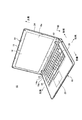
図1は、本発明の一実施形態に係るタッチパッド20を備えた電子機器10の斜視図である。なお、図1は、ヒンジ装置12によってディスプレイ筐体14を本体筐体16から開いて電子機器10をノート型PCの使用形態とした状態を示している。
<Outline of electronic devices>
FIG. 1 is a perspective view of an
電子機器10は、ディスプレイ筐体14を本体筐体16に対して閉じた0度位置から反転させた360度位置まで開閉可能に構成された、いわゆるコンバーチブル型PCである。従って、電子機器10は、ディスプレイ筐体14を本体筐体16に対して90度前後の角度位置に回動させた状態ではノート型PCとして好適に使用でき(図1参照)、ディスプレイ筐体14を本体筐体16に対して360度位置まで回動させて反転させた状態ではタブレット型PCとして好適に使用できる。本実施の形態ではこのようなコンバーチブル型PC以外、例えばディスプレイ筐体が180度位置程度までしか回動しない一般的なノート型PC、1つの筐体にディスプレイ装置を設けたタブレット型PC、携帯電話、スマートフォン又は電子手帳等、各種電子機器に適用できる。
The
以下、図1に示すようにディスプレイ筐体14を本体筐体16から90度程度に開いてノート型PCの使用形態とした状態を基準とし、ディスプレイ筐体14のヒンジ装置12側を下側(下端)、その反対側を上側(上端)と呼んで説明する。また、本体筐体16のヒンジ装置12側を後側(後端)、その反対側を前側(前端)と呼び、ディスプレイ筐体14及び本体筐体16の幅方向をそれぞれ左側及び右側と呼んで説明する。
Hereinafter, as shown in FIG. 1, based on the state where the
図1に示すように、電子機器10は、ディスプレイ筐体14の下端部14aと本体筐体16の後端部16aとを左右一対のヒンジ装置12によって回動可能に連結したものである。
As shown in FIG. 1, the
ディスプレイ筐体14は、その内面にディスプレイ装置18が設けられている。ディスプレイ筐体14は、ベゼル部材19とカバー部材24とを重ねて連結することで本体筐体16よりも薄い平板形状の箱体に構成されている。
A
ディスプレイ装置18は、例えばタッチパネル式の液晶表示装置によって構成される。ディスプレイ装置18は、表示面18a以外が金属や導電性フィルムで覆われている。
The
ベゼル部材19は、樹脂製の枠状部材である。ベゼル部材19は、ディスプレイ装置18の周縁部を囲んで保持するものである。カバー部材24は、樹脂製の板状部材の周縁部にベゼル部材19側に起立する壁部を設けた構成である。カバー部材24は、ディスプレイ筐体14の側面及び背面を覆うものである。ディスプレイ筐体14は、カバー部材24にねじ止め固定されたヒンジ装置12を介して本体筐体16と連結される。ディスプレイ筐体14は、ヒンジ装置12を通過した図示しないケーブルにより本体筐体16と電気的に接続される。
The
本体筐体16は、平板形状に構成された箱体であり、その内面にキーボード装置26やタッチパッド20が設けられている。本体筐体16は、その内部に図示しない基板、演算装置及びメモリ等の各種の電子部品が収納されている。キーボード装置26は、例えばタッチパネル式の液晶表示装置に仮想キーボードを表示するソフトウェアキーボード等であってもよい。キーボード装置26の中央には、トラックポイント28が設けられる。トラックポイント28は、突起状のボタンで、ホームポジションから手を離さずにカーソルの操作を行うことができる。
The
<タッチパッドの概要>
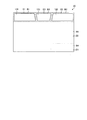
図2は、タッチパッド20の概要を示す平面図である。図2に示すように、タッチパッド20は、マウスボタンに対応したセンターボタン(ミドルボタン)であるボタンB3と、ボタンB3の左に隣接配置される左ボタン(主ボタン)であるボタンB1と、ボタンB3の右に隣接配置される右ボタン(副ボタン)であるボタンB2との機能を有したマウスボタン機能付きのタッチパッドである。
<Outline of touchpad>
FIG. 2 is a plan view showing an outline of the
ボタンB1は、第1ボタン領域である領域E1の押圧によってマウスの左ボタンのように選択、移動、実行などの操作を行う機能を有する。ボタンB2は、第2ボタン領域である領域E2の押圧によってマウスの右ボタンのようにカーソルが置かれた位置において使用できる機能を表示する機能を有する。また、ボタンB3は、センターボタン領域である領域E3が押圧されたときに、トラックポイント28が指示する方向に画面をスクロールさせる機能を有する。すなわち、ボタンB1〜B3は、マウスボタンに対応したボタンである。
The button B1 has a function of performing operations such as selection, movement, and execution like a left button of a mouse when the area E1 which is the first button area is pressed. The button B2 has a function of displaying a function that can be used at the position where the cursor is placed, like the right button of the mouse, by pressing the area E2 that is the second button area. Further, the button B3 has a function of scrolling the screen in the direction designated by the
なお、タッチパッド20のその他領域には、例えば右下隅の領域E4に、ボタンB2と同じ右ボタンの機能を有するボタンB4が配置され、領域E5には、ドラッグアンドリリース、各種ジェスチャー操作、クリック操作などを行うボタンB5が配置される。すなわち、タッチパッド20は、5つのボタンB1〜B5を有する。なお、各ボタンB1〜B5には、上記操作設定に限らず、各種機能を割り付けることができるとともに、キーボード装置26のキー押下とともにさらに多種機能を割り付けることもできる。
In the other area of the
タッチパッド20の全面には、3軸(X,Y,Z方向)の荷重センサ31が配置されている。荷重センサ31は、押された時に応じた上部と下部との接触抵抗値変化を読み取って圧力の強さを検出する。荷重センサ31は、例えば、ひずみゲージセンサであるが、圧電型等の他の種類のセンサであってもよい。なお、マウスボタンに対応した領域E1〜E3のみに荷重センサ31を設け、領域E1〜E3の他の領域に他のタッチセンサである静電容量センサを設けるようにしてもよい。また、タッチパッド20の全面に、Z方向のみの荷重を検出する簡易な荷重センサと、X,Y方向の位置を検出する静電容量センサとを重ね合わせたセンサ配置としてもよい。
A triaxial (X, Y, Z direction)
領域E1,E2の面上前側には、領域E1,E2の領域の境界を触覚検知できる突起である指標21,22が境界近傍に設けられる。また、領域E3の面上前側にも、領域E3の境界を触覚検知できる突起である指標23が境界近傍に設けられる。指標21,22は、線状のバーを印刷したものであり、指標23は、複数のドットを横並びに印刷したものである。すなわち、指標21又は指標22の少なくとも一方と指標23とは、異なる形状としている。なお、指標21〜23は、各領域E1〜E3の全てに設ける必要はなく、いずれか1つ以上であってもよい。
On the front side on the surface of the regions E1 and E2,
なお、ボタンB1〜B3は、タッチパッド20の後側に設けているが、前側に設けるものであってもよい。
Although the buttons B1 to B3 are provided on the rear side of the
<タッチ検出動作>
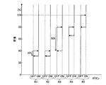
図3は、各ボタンB1〜B5への荷重に対するタッチのオンオフ設定を説明する説明図である。なお、図3に示した荷重の値は、ボタンB5がオンする上限値を100%として正規化した値を示している。
<Touch detection operation>
FIG. 3 is an explanatory diagram illustrating ON/OFF setting of touch with respect to the load on each of the buttons B1 to B5. The load values shown in FIG. 3 are normalized by setting the upper limit value at which the button B5 is turned on to 100%.
図3に示すように、ボタンB1,B2は、40%以上の荷重を検出した場合、オン状態(押下状態)であると検出され、その後32%以下の荷重を検出した場合、オフ状態であると検出される。ボタンB3は、80%以上の荷重を検出した場合、オン状態であると検出され、その後40%以下の荷重を検出した場合、オフ状態であると検出される。ボタンB4は、80%以上の荷重を検出した場合、オン状態であると検出され、その後66%以下の荷重を検出した場合、オフ状態であると検出される。また、ボタンB5は、100%以上の荷重を検出した場合、オン状態であると検出され、その後80%以下の荷重を検出した場合、オフ状態であると検出される。 As shown in FIG. 3, when the load of 40% or more is detected, the buttons B1 and B2 are detected to be in the on state (pressed state), and when the load of 32% or less is detected thereafter, they are in the off state. Is detected. The button B3 is detected to be in the ON state when a load of 80% or more is detected, and is detected to be in the OFF state when a load of 40% or less is detected thereafter. The button B4 is detected to be in the ON state when a load of 80% or more is detected, and is detected to be in the OFF state when a load of 66% or less is detected thereafter. The button B5 is detected to be in the ON state when a load of 100% or more is detected, and is detected to be in the OFF state when a load of 80% or less is detected thereafter.
すなわち、ボタンB3の上限値の荷重と、ボタンB1,B2の上限値の荷重とを異なるようにしている。具体的には、ボタンB3の上限値の荷重を、ボタンB1,B2の上限値の荷重よりも大きくしている。これにより、ボタンB1,B2のタッチとボタンB3とのタッチとを峻別している。例えば、ボタンB1をタッチする場合にボタンB3にも触れてしまった場合、ボタンB1の上限値はボタンB3の上限値よりも小さいので先にタッチ検出され、ボタンB3への誤操作タッチを排除することができる。 That is, the upper limit load of the button B3 and the upper limit load of the buttons B1 and B2 are made different. Specifically, the load of the upper limit value of the button B3 is made larger than the load of the upper limit value of the buttons B1 and B2. Thereby, the touch of the buttons B1 and B2 and the touch of the button B3 are distinguished. For example, when the button B3 is also touched when the button B1 is touched, the upper limit value of the button B1 is smaller than the upper limit value of the button B3, and thus the touch is detected first, and the erroneous operation touch on the button B3 is eliminated. You can
なお、領域E1又は領域E2の少なくとも一方の最大荷重と、領域E3の最大荷重とが同時にそれぞれボタンの上限値以上であると検出された場合は、それぞれの最大荷重の位置が所定距離以上離隔している場合に、ボタンB1またはボタンB2と、ボタンB3とが同時に押下されたと判定される。一方、それぞれの最大荷重の位置が所定距離よりも離隔していない場合、より最大荷重が大きい領域が押下されたと判定されればよい。 In addition, when the maximum load of at least one of the area E1 and the area E2 and the maximum load of the area E3 are simultaneously detected to be equal to or more than the upper limit value of the button, the positions of the respective maximum loads are separated by a predetermined distance or more. If it is, it is determined that the button B1 or the button B2 and the button B3 are simultaneously pressed. On the other hand, when the positions of the respective maximum loads are not separated from each other by more than the predetermined distance, it may be determined that the region having the larger maximum load is pressed.
また、各ボタンB1〜B5は、荷重が上限値以上の荷重を検出した場合、オン状態に移行し、その後下限値以下の荷重を検出した場合、オフ状態に移行するヒステリシス特性を持たせ、各ボタンB1〜B5のオン状態判定の安定性を持たせている。 In addition, each of the buttons B1 to B5 has a hysteresis characteristic that transitions to an ON state when a load having a load equal to or higher than an upper limit value is detected, and transitions to an OFF state when a load having a load equal to or lower than a lower limit value is detected. The stability of the on-state determination of the buttons B1 to B5 is provided.
さらに、他のボタンB1、B2,B4,B5の上限値に対する下限値の下降割合は20%であるのに対し、ボタンB3の上限値に対する下限値の下降割合を50%として大きくしている。ボタンB3及びトラックポイント28を用いて画面スクロールを行う場合、ボタンB3を押下し続ける必要があり、また、ボタンB3に対する上限値が大きいため、操作中における操作者によるボタンB3の荷重が減少しやすい。このため、ボタンB3に対する下降割合を大きくして、オン状態を維持しやすくし、オン状態継続による操作の安定性を向上させている。
Further, while the lower limit of the lower limit value of the other buttons B1, B2, B4, B5 is 20%, the lower limit value of the lower limit value of the button B3 is increased to 50%. When screen scrolling is performed using the button B3 and the
なお、ボタンB4,B5の荷重の上限値を大きくしているのは、操作中における誤操作を防ぐためである。 The upper limits of the loads on the buttons B4 and B5 are increased in order to prevent erroneous operation during operation.
<タッチパッドの制御系>
図4は、タッチパッド20の制御系を示すブロック図である。図4に示すように、タッチパッド20は、荷重センサ31、振動アクチュエータ32、表示部33、入力部34、記憶部35及び制御部36を有する。荷重センサ31は、上述したので省略する。振動アクチュエータ32は、荷重センサ31の裏面に配置され、タッチがオン状態になったとき及びタッチがオフ状態になったときに、触覚振動を与えるハプティクスを実現するものである。表示部33は、ディスプレイ装置18である。入力部34は、タッチパッド20、キーボード装置26、タッチパッド20を含む各種入力デバイスである。
<Control system of touchpad>
FIG. 4 is a block diagram showing a control system of the
記憶部35は、ハードディスク装置や不揮発性メモリ等からなる記憶デバイスであり、タッチ設定情報D1を記憶する。
The
制御部36は、電子機器10の全体を制御する制御部であり、タッチ検出処理部37、触覚処理部38及び設定処理部39を有する。制御部36は、タッチ検出処理部37、触覚処理部38及び設定処理部39にそれぞれ対応するプログラムを不揮発性メモリや磁気ディスク装置などの記憶装置に記憶しておき、これらのプログラムをメモリにロードして、CPUで実行することで、対応するプロセスを実行させることになる。
The control unit 36 is a control unit that controls the entire
タッチ検出処理部37は、各ボタンB1〜B5に対するタッチ設定情報D1をもとに、上述したタッチ検出処理を行う。触覚処理部38は、荷重が上限値以上となってオン状態になったとき、及び荷重が下限値以下となってオフ状態になったとき、振動アクチュエータ32を介して触覚振動を与える。設定処理部39は、各ボタンB1〜B5に対する設定情報をタッチ設定情報D1として記憶する処理を行う。
The touch
<タッチ検出処理>
次に、図5に示したフローチャートを参照してタッチ検出処理部37によるタッチ検出処理手順について説明する。まず、タッチ検出処理部37は、荷重を検出した検出面積が上限面積以下、かつ、下限面積以上であるか否かを判定する(ステップS101)。検出面積が上限面積以下、かつ、下限面積以上とは、検出面積が操作者の指のタッチ面積であるか否かを判定するためです。検出面積が上限面積を超える場合は、指のタッチ面積を超えるため誤操作と判定する。また、検出面積が下限面積未満である場合は、指の押圧が不完全であり、タッチ意思がないものと判定する。荷重を検出した検出面積が上限面積以下、かつ、下限面積以上でない場合(ステップS101,No)には、本処理を終了する。
<Touch detection processing>
Next, a touch detection processing procedure by the touch
一方、荷重を検出した検出面積が上限面積以下、かつ、下限面積以上である場合(ステップS101,Yes)には、さらに、荷重は上限値以上であるか否かを判定する(ステップS102)。荷重が上限値以上でない場合(ステップS102,No)には、本処理を終了する。 On the other hand, when the detected area where the load is detected is less than or equal to the upper limit area and greater than or equal to the lower limit area (Yes in step S101), it is further determined whether the load is greater than or equal to the upper limit value (step S102). If the load is not equal to or more than the upper limit value (step S102, No), this processing ends.
一方、荷重は上限値以上である場合(ステップS102,Yes)には、現在のタッチ状態をオン状態として判定する(ステップS103)。その後、荷重は下限値以下であるか否かを判定する(ステップS104)。荷重が下限値以下でない場合(ステップS104,No)には、ステップS103に移行し、オン状態を維持する。 On the other hand, when the load is equal to or more than the upper limit value (step S102, Yes), the current touch state is determined to be the on state (step S103). Then, it is determined whether the load is less than or equal to the lower limit value (step S104). If the load is not less than or equal to the lower limit value (step S104, No), the process proceeds to step S103 and the ON state is maintained.
荷重が下限値以下である場合(ステップS104,Yes)には、現在のタッチ状態をオフ状態と判定し(ステップS105)、本処理を終了する。なお、上述した処理は、所定時間毎に繰り返し行う。 When the load is less than or equal to the lower limit value (Yes in step S104), it is determined that the current touch state is the off state (step S105), and this processing ends. Note that the above-described processing is repeatedly performed every predetermined time.
<変形例1>
上記の実施の形態では、タッチパッド20のボタンB1〜B5の領域E1〜E5毎に、荷重の上限値を設定していたが、本変形例1では、ボタンB3内の一部領域に、個別に荷重の上限値を設定している。
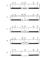
<Modification 1>
In the above-described embodiment, the upper limit value of the load is set for each of the areas E1 to E5 of the buttons B1 to B5 of the
図6は、本変形例1に係るタッチパッド20の概要を示す平面図である。図6に示すように、本変形例1では、領域E3に、少なくとも領域E1又は領域E2との境界線の一方の端部付近に隅領域である領域E31,E32を設けている。具体的には、ボタンB3の領域E3の左前部分の領域E31及び右前部分の領域E32に対し、図2に示した領域E3と同じ上限値(80%)を設定し、領域E31,E32以外の領域E3に対し、領域E1,E2と同じ上限値(40%)を設定している。
FIG. 6 is a plan view showing the outline of the
操作者は、キーボード装置26に対して手をホームポジションに置きつつ、親指によってボタンB3を押下するが、この場合、親指は領域E31,E32の部分を押下する場合が多い。したがって、この領域E31,E32のみに、図2に示した領域E3と同じ設定をすることによって、実施の形態と同じ作用効果を得ることができる The operator presses the button B3 with the thumb while placing the hand on the keyboard device 26 at the home position. In this case, the thumb often presses the regions E31 and E32. Therefore, by setting the same settings as those of the region E3 shown in FIG. 2 only in these regions E31 and E32, it is possible to obtain the same effect as the embodiment.
なお、領域E31,E32の荷重の上限値を、図2に示した領域E3よりも大きい上限値を設定し、領域E31,E32以外の領域E3の上限値を、図2に示した領域E3と同じ上限値を設定するようにしてもよい。 It should be noted that the upper limit value of the load in the areas E31 and E32 is set to be larger than that in the area E3 shown in FIG. 2, and the upper limit value of the area E3 other than the areas E31 and E32 is set to the area E3 shown in FIG. You may make it set the same upper limit.
<変形例2>
上記の実施の形態では、タッチパッド20のボタンB1〜B5の領域E1〜E5の荷重の上限値は、表面上同一の値に設定していたが、本変形例2では、領域E1,E2の上限値を、領域E1,E3,E2が並ぶ方向であるX方向(第1方向)に直交するY方向(第2方向)の一方、例えば前側に向かって値が下がる傾斜特性を持たせ、領域E3の上限値を、第2方向の他方である後側に向かって値が上がる傾斜特性を持たせている。
<Modification 2>
In the above-described embodiment, the upper limit values of the loads of the areas E1 to E5 of the buttons B1 to B5 of the
図7は、本変形例2に係るタッチパッド20の概要を示す平面図である。図7に示すように、本変形例2では、領域E1,E2の荷重の上限値が前側に向かうに従って小さくなるように設定し、領域E3の荷重の上限値が後側に行くに従って大きくなるようにしている。
FIG. 7 is a plan view showing the outline of the
このような上限値の傾斜特性は、ボタンB1〜B3が物理ボタンであって、物理ボタンが傾斜している場合に、同じ触覚荷重でオン状態になるようにしている。操作者が物理ボタンからボタンB1〜B3に変更した場合に、操作感覚が似ているため、スムーズにボタンB1〜B3の取り扱い操作に慣れることができる。図7の場合は、ボタンB3に対応する物理ボタンが後側に向けて上昇する傾斜をもち、ボタンB1,B2に対応する物理ボタンが前側に向けて上昇する傾斜をもつ場合に対応した上限値の傾斜特性を設定している。すなわち、本変形例2では、操作者が慣れ親しんだ物理ボタンの傾斜に合わせて上限値の傾斜特性を持たせるものである。 The tilt characteristic of the upper limit value is such that when the buttons B1 to B3 are physical buttons and the physical buttons are tilted, they are turned on with the same tactile load. When the operator changes from the physical buttons to the buttons B1 to B3, since the operation feeling is similar, it is possible to smoothly get used to the handling operation of the buttons B1 to B3. In the case of FIG. 7, the upper limit value corresponding to the case where the physical button corresponding to the button B3 has an inclination to rise toward the rear side and the physical button corresponding to the buttons B1 and B2 has an inclination to rise toward the front side. The inclination characteristic of is set. That is, in the second modified example, the tilt characteristic of the upper limit value is provided according to the tilt of the physical button that the operator is familiar with.
<変形例3>
上記の実施の形態では、ボタンB1〜B3の領域E1〜E3の前側に指標21〜23を設けていたが、本変形例3では、領域E1〜E3の境界に対応して領域全体を持ち上げる指標121〜123を設けている。
<Modification 3>
In the above-described embodiment, the
図8は、本変形例3に係るタッチパッド20の概要を示す平面図である。図8に示すように、本変形例3では、それぞれ領域E1〜E3の境界から所定幅分、内側に小さくした形状のテープなどの薄い板状部材で形成された指標121〜123を配置して突起状態としている。各指標121〜123の上面の辺は、指標として機能する。
FIG. 8 is a plan view showing the outline of the
なお、指標121〜123に代えて、指標121〜123の周縁のみを突起状態としてもよいし、指標121〜123の周縁を離散的に突起状態としてもよい。また、指標121〜123の表面にエンボス加工などを施し、ボタンB1,B2とボタンB3とのエンボス加工を異ならせることが好ましい。さらに、これらの指標121〜123のエンボス加工に代えて、荷重センサ31のカバー表面に対して突起やエンボス加工などによる指標を一体的に形成してもよい。
Note that instead of the
<変形例4>
図9は、本変形例4に係るボタンB1〜B3の指標の一例を示す図である。図9に示すように、図9(a)では、図2に示した指標23に代えて、密集した3つのドッドとしている。また、図9(b)では、図2に示した指標23に代えて、均等配置した3つのドットとしている。さらに、図9(c)では、図2に示した指標23に代えて、均等配置した4つのドットとしている。また、図9(d)では、図2に示した5つのドットの指標23に代えて、指標23を後側にシフトした指標23dとしている。さらに、図9(e)では、図2に示した指標23を設けないようにしている。なお、指標21〜23,23a〜23dの高さを全体的に変化させてもよいし、各指標間で高さを異ならせるようにしてもよい。
<Modification 4>
FIG. 9 is a diagram showing an example of the indexes of the buttons B1 to B3 according to the fourth modification. As shown in FIG. 9, in FIG. 9A, the
なお、上記の実施の形態及び変形例で図示した各構成は機能概略的なものであり、必ずしも物理的に図示の構成をされていることを要しない。すなわち、各装置及び構成要素の分散・統合の形態は図示のものに限られず、その全部又は一部を各種の使用状況などに応じて、任意の単位で機能的又は物理的に分散・統合して構成することができる。 It should be noted that the configurations illustrated in the above-described embodiments and modifications are functionally schematic, and do not necessarily have to be physically configured as illustrated. That is, the form of distribution/integration of each device and component is not limited to that shown in the figure, and all or a part of them may be functionally or physically distributed/integrated in arbitrary units according to various usage conditions. Can be configured.
10 電子機器
12 ヒンジ装置
14 ディスプレイ筐体
14a 下端部
16 本体筐体
16a 後端部
18 ディスプレイ装置
18a 表示面
19 ベゼル部材
20 タッチパッド
21〜23,23a〜23d,121〜123 指標
24 カバー部材
26 キーボード装置
28 トラックポイント
31 荷重センサ
32 振動アクチュエータ
33 表示部
34 入力部
35 記憶部
36 制御部
37 タッチ検出処理部
38 触覚処理部
39 設定処理部
B1〜B5 ボタン
D1 タッチ設定情報
E1〜E5,E31,E32 領域
DESCRIPTION OF
Claims (12)
センターボタン領域と、
前記センターボタン領域に隣接配置される第1ボタン領域と、
前記センターボタン領域の、前記第1ボタン領域とは反対側に隣接配置される第2ボタン領域と、
少なくとも前記センターボタン領域、前記第1ボタン領域及び前記第2ボタン領域の荷重を検出する荷重センサと、
前記荷重センサが、前記第1ボタン領域及び前記第2ボタン領域の少なくとも一方においては第1上限値以上の荷重を検出した場合に押下状態と判定し、前記センターボタン領域においては第2上限値以上の荷重を検出した場合に押下状態と判定するする制御部と、
を備え、
前記第2上限値と前記第1上限値とは異なる値であることを特徴とするタッチパッド。 A touchpad,
Center button area,
A first button area disposed adjacent to the center button area,
A second button area adjacent to the center button area opposite to the first button area;
A load sensor for detecting a load on at least the center button area, the first button area, and the second button area;
When the load sensor detects a load equal to or more than a first upper limit value in at least one of the first button area and the second button area, it is determined as a pressed state, and in the center button area, a second upper limit value or more. A control unit that determines that the pressed state is detected when the load of
Equipped with
The touch pad, wherein the second upper limit and the first upper limit are different values.
前記制御部は、前記隅領域において前記第2上限値以上の荷重を検出した場合に、前記センサーボタン領域が押下状態であることを検出し、前記隅領域以外の前記センター領域において前記第1上限値以上の荷重を検出した場合に、前記センサーボタン領域が押下状態であることを検出することを特徴とする請求項2に記載のタッチパッド。 The center button area has a corner area at least near one end of a boundary line with one of the first button area or the second button area,
The control unit detects that the sensor button area is in a pressed state when detecting a load equal to or more than the second upper limit value in the corner area, and the first upper limit in the center area other than the corner area. The touch pad according to claim 2, wherein when the load equal to or more than a value is detected, it is detected that the sensor button area is in a pressed state.
前記制御部は、前記隅領域において前記第2上限値よりも大きい第3上限値以上の荷重を検出した場合に、前記センサーボタン領域が押下状態であることを検出することを特徴とする請求項2に記載のタッチパッド。 The center button area has a corner area at least near one end of a boundary line with one of the first button area or the second button area,
The control unit detects that the sensor button region is in a pressed state when a load equal to or greater than a third upper limit value that is greater than the second upper limit value is detected in the corner region. The touch pad described in 2.
前記第1上限値は、前記第2方向の一方に向かって値が下がる傾斜特性を有し、
前記第2上限値は、前記第2方向の他方に向かって値が上がる傾斜特性を有することを特徴とする請求項1に記載のタッチパッド。 When the direction in which the first button area, the center button area, and the second button area are arranged is the first direction, and the direction orthogonal to the first direction on the touch pad surface is the second direction,
The first upper limit value has an inclination characteristic in which the value decreases toward one of the second directions,
The touch pad according to claim 1, wherein the second upper limit value has an inclination characteristic in which the value increases toward the other side in the second direction.
Priority Applications (2)
| Application Number | Priority Date | Filing Date | Title |
|---|---|---|---|
| JP2019007989A JP2020119099A (en) | 2019-01-21 | 2019-01-21 | Touch pad and electronic apparatus |
| US16/420,001 US10747340B2 (en) | 2019-01-21 | 2019-05-22 | Touch pad and electronic apparatus |
Applications Claiming Priority (1)
| Application Number | Priority Date | Filing Date | Title |
|---|---|---|---|
| JP2019007989A JP2020119099A (en) | 2019-01-21 | 2019-01-21 | Touch pad and electronic apparatus |
Publications (1)
| Publication Number | Publication Date |
|---|---|
| JP2020119099A true JP2020119099A (en) | 2020-08-06 |
Family
ID=71608388
Family Applications (1)
| Application Number | Title | Priority Date | Filing Date |
|---|---|---|---|
| JP2019007989A Pending JP2020119099A (en) | 2019-01-21 | 2019-01-21 | Touch pad and electronic apparatus |
Country Status (2)
| Country | Link |
|---|---|
| US (1) | US10747340B2 (en) |
| JP (1) | JP2020119099A (en) |
Families Citing this family (1)
| Publication number | Priority date | Publication date | Assignee | Title |
|---|---|---|---|---|
| JP6724259B2 (en) * | 2017-10-31 | 2020-07-15 | 富士フイルム株式会社 | Operating device, its operating method and operating program |
Family Cites Families (10)
| Publication number | Priority date | Publication date | Assignee | Title |
|---|---|---|---|---|
| US20100097324A1 (en) * | 2008-10-20 | 2010-04-22 | Dell Products L.P. | Parental Controls Based on Touchscreen Input |
| US8416065B2 (en) * | 2009-06-30 | 2013-04-09 | Research In Motion Limited | Overlay for electronic device and method of identifying same |
| KR101750300B1 (en) * | 2011-11-18 | 2017-06-23 | 센톤스 아이엔씨. | Detecting touch input force |
| JP6032101B2 (en) | 2013-03-29 | 2016-11-24 | 富士通株式会社 | INPUT DEVICE AND ELECTRONIC DEVICE HAVING THE INPUT DEVICE |
| JPWO2016208099A1 (en) * | 2015-06-24 | 2018-04-12 | パナソニックIpマネジメント株式会社 | Information processing apparatus, input control method for controlling input to information processing apparatus, and program for causing information processing apparatus to execute input control method |
| US10180755B2 (en) * | 2016-02-29 | 2019-01-15 | Apple Inc. | Electronic device with dynamic thresholding for force detection |
| US10564839B2 (en) * | 2016-03-31 | 2020-02-18 | Sensel Inc. | Method for detecting and characterizing inputs on a touch sensor surface |
| US10402042B2 (en) * | 2016-06-13 | 2019-09-03 | Lenovo (Singapore) Pte. Ltd. | Force vector cursor control |
| KR102364420B1 (en) * | 2017-04-26 | 2022-02-17 | 삼성전자 주식회사 | Electronic device and method of controlling the electronic device based on touch input |
| US10639543B2 (en) * | 2018-03-23 | 2020-05-05 | Valve Corporation | Handheld controllers with touch-sensitive controls |
-
2019
- 2019-01-21 JP JP2019007989A patent/JP2020119099A/en active Pending
- 2019-05-22 US US16/420,001 patent/US10747340B2/en active Active
Also Published As
| Publication number | Publication date |
|---|---|
| US20200233507A1 (en) | 2020-07-23 |
| US10747340B2 (en) | 2020-08-18 |
Similar Documents
| Publication | Publication Date | Title |
|---|---|---|
| EP2820519B1 (en) | Force concentrator | |
| US20140374230A1 (en) | Pressure sensitive keys with a single-sided direct conduction sensor | |
| US10678366B2 (en) | Force sensor array | |
| JP2020119099A (en) | Touch pad and electronic apparatus | |
| CN110858112A (en) | Input device | |
| WO2016158125A1 (en) | Electronic device |