JP2020096834A - Enhanced multicore fiber endoscopes - Google Patents
Enhanced multicore fiber endoscopes Download PDFInfo
- Publication number
- JP2020096834A JP2020096834A JP2019224599A JP2019224599A JP2020096834A JP 2020096834 A JP2020096834 A JP 2020096834A JP 2019224599 A JP2019224599 A JP 2019224599A JP 2019224599 A JP2019224599 A JP 2019224599A JP 2020096834 A JP2020096834 A JP 2020096834A
- Authority
- JP
- Japan
- Prior art keywords
- core
- endoscope
- fiber
- cores
- illumination
- Prior art date
- Legal status (The legal status is an assumption and is not a legal conclusion. Google has not performed a legal analysis and makes no representation as to the accuracy of the status listed.)
- Pending
Links
- 239000000835 fiber Substances 0.000 title claims abstract description 216
- 238000005286 illumination Methods 0.000 claims abstract description 126
- 230000003287 optical effect Effects 0.000 claims abstract description 91
- 230000001427 coherent effect Effects 0.000 claims abstract description 7
- 238000012545 processing Methods 0.000 claims abstract description 4
- 238000003384 imaging method Methods 0.000 claims description 109
- 238000000034 method Methods 0.000 claims description 57
- 238000007689 inspection Methods 0.000 claims description 36
- 238000001839 endoscopy Methods 0.000 claims description 17
- 238000013461 design Methods 0.000 claims description 14
- 239000000463 material Substances 0.000 claims description 14
- 239000000975 dye Substances 0.000 claims description 13
- 230000002093 peripheral effect Effects 0.000 claims description 12
- 230000005855 radiation Effects 0.000 claims description 11
- 238000004458 analytical method Methods 0.000 claims description 6
- 230000003321 amplification Effects 0.000 claims description 5
- 239000011248 coating agent Substances 0.000 claims description 5
- 238000000576 coating method Methods 0.000 claims description 5
- 230000000694 effects Effects 0.000 claims description 5
- 230000007246 mechanism Effects 0.000 claims description 5
- 238000003199 nucleic acid amplification method Methods 0.000 claims description 5
- 238000001069 Raman spectroscopy Methods 0.000 claims description 4
- 239000007850 fluorescent dye Substances 0.000 claims description 4
- 239000004038 photonic crystal Substances 0.000 claims description 4
- 238000001228 spectrum Methods 0.000 claims description 4
- 229910052751 metal Inorganic materials 0.000 claims description 3
- 239000002184 metal Substances 0.000 claims description 3
- 239000000203 mixture Substances 0.000 claims description 3
- 230000002123 temporal effect Effects 0.000 abstract 1
- 239000011162 core material Substances 0.000 description 202
- 238000005070 sampling Methods 0.000 description 9
- 230000010287 polarization Effects 0.000 description 7
- 230000008569 process Effects 0.000 description 7
- 230000005540 biological transmission Effects 0.000 description 5
- 230000008901 benefit Effects 0.000 description 4
- 238000005253 cladding Methods 0.000 description 4
- 238000004590 computer program Methods 0.000 description 4
- 239000013307 optical fiber Substances 0.000 description 4
- 238000001574 biopsy Methods 0.000 description 3
- 230000015572 biosynthetic process Effects 0.000 description 3
- 238000010276 construction Methods 0.000 description 3
- 238000009826 distribution Methods 0.000 description 3
- 238000004519 manufacturing process Methods 0.000 description 3
- 210000001747 pupil Anatomy 0.000 description 3
- 238000007493 shaping process Methods 0.000 description 3
- 238000003860 storage Methods 0.000 description 3
- 238000000701 chemical imaging Methods 0.000 description 2
- 239000012530 fluid Substances 0.000 description 2
- 230000010354 integration Effects 0.000 description 2
- 238000013532 laser treatment Methods 0.000 description 2
- 239000007788 liquid Substances 0.000 description 2
- 238000001465 metallisation Methods 0.000 description 2
- 238000012986 modification Methods 0.000 description 2
- 230000004048 modification Effects 0.000 description 2
- 238000012634 optical imaging Methods 0.000 description 2
- 230000009467 reduction Effects 0.000 description 2
- 238000000926 separation method Methods 0.000 description 2
- 238000012546 transfer Methods 0.000 description 2
- 229910052691 Erbium Inorganic materials 0.000 description 1
- 241000295146 Gallionellaceae Species 0.000 description 1
- 208000000913 Kidney Calculi Diseases 0.000 description 1
- 206010029148 Nephrolithiasis Diseases 0.000 description 1
- 230000008859 change Effects 0.000 description 1
- 238000006243 chemical reaction Methods 0.000 description 1
- 239000003086 colorant Substances 0.000 description 1
- 238000004891 communication Methods 0.000 description 1
- 230000000295 complement effect Effects 0.000 description 1
- 230000006835 compression Effects 0.000 description 1
- 238000007906 compression Methods 0.000 description 1
- 238000001514 detection method Methods 0.000 description 1
- 238000010586 diagram Methods 0.000 description 1
- 239000006185 dispersion Substances 0.000 description 1
- 238000012377 drug delivery Methods 0.000 description 1
- UYAHIZSMUZPPFV-UHFFFAOYSA-N erbium Chemical compound [Er] UYAHIZSMUZPPFV-UHFFFAOYSA-N 0.000 description 1
- 238000003780 insertion Methods 0.000 description 1
- 230000037431 insertion Effects 0.000 description 1
- 238000009434 installation Methods 0.000 description 1
- 238000013507 mapping Methods 0.000 description 1
- 239000011159 matrix material Substances 0.000 description 1
- 238000005457 optimization Methods 0.000 description 1
- 210000000056 organ Anatomy 0.000 description 1
- 238000001126 phototherapy Methods 0.000 description 1
- 229920000642 polymer Polymers 0.000 description 1
- 229920005594 polymer fiber Polymers 0.000 description 1
- 239000004065 semiconductor Substances 0.000 description 1
- 230000035945 sensitivity Effects 0.000 description 1
- 125000006850 spacer group Chemical group 0.000 description 1
- 230000003595 spectral effect Effects 0.000 description 1
- 238000006467 substitution reaction Methods 0.000 description 1
- 238000012360 testing method Methods 0.000 description 1
- 238000002560 therapeutic procedure Methods 0.000 description 1
- 238000011282 treatment Methods 0.000 description 1
- 210000000626 ureter Anatomy 0.000 description 1
- 239000011800 void material Substances 0.000 description 1
Images


Classifications
-
- A—HUMAN NECESSITIES
- A61—MEDICAL OR VETERINARY SCIENCE; HYGIENE
- A61B—DIAGNOSIS; SURGERY; IDENTIFICATION
- A61B1/00—Instruments for performing medical examinations of the interior of cavities or tubes of the body by visual or photographical inspection, e.g. endoscopes; Illuminating arrangements therefor
- A61B1/06—Instruments for performing medical examinations of the interior of cavities or tubes of the body by visual or photographical inspection, e.g. endoscopes; Illuminating arrangements therefor with illuminating arrangements
- A61B1/063—Instruments for performing medical examinations of the interior of cavities or tubes of the body by visual or photographical inspection, e.g. endoscopes; Illuminating arrangements therefor with illuminating arrangements for monochromatic or narrow-band illumination
-
- A—HUMAN NECESSITIES
- A61—MEDICAL OR VETERINARY SCIENCE; HYGIENE
- A61B—DIAGNOSIS; SURGERY; IDENTIFICATION
- A61B1/00—Instruments for performing medical examinations of the interior of cavities or tubes of the body by visual or photographical inspection, e.g. endoscopes; Illuminating arrangements therefor
- A61B1/00002—Operational features of endoscopes
- A61B1/00004—Operational features of endoscopes characterised by electronic signal processing
- A61B1/00009—Operational features of endoscopes characterised by electronic signal processing of image signals during a use of endoscope
- A61B1/000094—Operational features of endoscopes characterised by electronic signal processing of image signals during a use of endoscope extracting biological structures
-
- A—HUMAN NECESSITIES
- A61—MEDICAL OR VETERINARY SCIENCE; HYGIENE
- A61B—DIAGNOSIS; SURGERY; IDENTIFICATION
- A61B1/00—Instruments for performing medical examinations of the interior of cavities or tubes of the body by visual or photographical inspection, e.g. endoscopes; Illuminating arrangements therefor
- A61B1/00064—Constructional details of the endoscope body
- A61B1/00071—Insertion part of the endoscope body
- A61B1/0008—Insertion part of the endoscope body characterised by distal tip features
- A61B1/00096—Optical elements
-
- A—HUMAN NECESSITIES
- A61—MEDICAL OR VETERINARY SCIENCE; HYGIENE
- A61B—DIAGNOSIS; SURGERY; IDENTIFICATION
- A61B1/00—Instruments for performing medical examinations of the interior of cavities or tubes of the body by visual or photographical inspection, e.g. endoscopes; Illuminating arrangements therefor
- A61B1/00163—Optical arrangements
- A61B1/00165—Optical arrangements with light-conductive means, e.g. fibre optics
- A61B1/00167—Details of optical fibre bundles, e.g. shape or fibre distribution
-
- A—HUMAN NECESSITIES
- A61—MEDICAL OR VETERINARY SCIENCE; HYGIENE
- A61B—DIAGNOSIS; SURGERY; IDENTIFICATION
- A61B1/00—Instruments for performing medical examinations of the interior of cavities or tubes of the body by visual or photographical inspection, e.g. endoscopes; Illuminating arrangements therefor
- A61B1/00163—Optical arrangements
- A61B1/00186—Optical arrangements with imaging filters
-
- A—HUMAN NECESSITIES
- A61—MEDICAL OR VETERINARY SCIENCE; HYGIENE
- A61B—DIAGNOSIS; SURGERY; IDENTIFICATION
- A61B1/00—Instruments for performing medical examinations of the interior of cavities or tubes of the body by visual or photographical inspection, e.g. endoscopes; Illuminating arrangements therefor
- A61B1/00163—Optical arrangements
- A61B1/00188—Optical arrangements with focusing or zooming features
-
- A—HUMAN NECESSITIES
- A61—MEDICAL OR VETERINARY SCIENCE; HYGIENE
- A61B—DIAGNOSIS; SURGERY; IDENTIFICATION
- A61B1/00—Instruments for performing medical examinations of the interior of cavities or tubes of the body by visual or photographical inspection, e.g. endoscopes; Illuminating arrangements therefor
- A61B1/04—Instruments for performing medical examinations of the interior of cavities or tubes of the body by visual or photographical inspection, e.g. endoscopes; Illuminating arrangements therefor combined with photographic or television appliances
- A61B1/042—Instruments for performing medical examinations of the interior of cavities or tubes of the body by visual or photographical inspection, e.g. endoscopes; Illuminating arrangements therefor combined with photographic or television appliances characterised by a proximal camera, e.g. a CCD camera
-
- A—HUMAN NECESSITIES
- A61—MEDICAL OR VETERINARY SCIENCE; HYGIENE
- A61B—DIAGNOSIS; SURGERY; IDENTIFICATION
- A61B1/00—Instruments for performing medical examinations of the interior of cavities or tubes of the body by visual or photographical inspection, e.g. endoscopes; Illuminating arrangements therefor
- A61B1/06—Instruments for performing medical examinations of the interior of cavities or tubes of the body by visual or photographical inspection, e.g. endoscopes; Illuminating arrangements therefor with illuminating arrangements
- A61B1/0661—Endoscope light sources
- A61B1/0669—Endoscope light sources at proximal end of an endoscope
-
- A—HUMAN NECESSITIES
- A61—MEDICAL OR VETERINARY SCIENCE; HYGIENE
- A61B—DIAGNOSIS; SURGERY; IDENTIFICATION
- A61B1/00—Instruments for performing medical examinations of the interior of cavities or tubes of the body by visual or photographical inspection, e.g. endoscopes; Illuminating arrangements therefor
- A61B1/06—Instruments for performing medical examinations of the interior of cavities or tubes of the body by visual or photographical inspection, e.g. endoscopes; Illuminating arrangements therefor with illuminating arrangements
- A61B1/07—Instruments for performing medical examinations of the interior of cavities or tubes of the body by visual or photographical inspection, e.g. endoscopes; Illuminating arrangements therefor with illuminating arrangements using light-conductive means, e.g. optical fibres
-
- G—PHYSICS
- G02—OPTICS
- G02B—OPTICAL ELEMENTS, SYSTEMS OR APPARATUS
- G02B23/00—Telescopes, e.g. binoculars; Periscopes; Instruments for viewing the inside of hollow bodies; Viewfinders; Optical aiming or sighting devices
- G02B23/24—Instruments or systems for viewing the inside of hollow bodies, e.g. fibrescopes
- G02B23/2407—Optical details
- G02B23/2461—Illumination
- G02B23/2469—Illumination using optical fibres
-
- G—PHYSICS
- G02—OPTICS
- G02B—OPTICAL ELEMENTS, SYSTEMS OR APPARATUS
- G02B23/00—Telescopes, e.g. binoculars; Periscopes; Instruments for viewing the inside of hollow bodies; Viewfinders; Optical aiming or sighting devices
- G02B23/24—Instruments or systems for viewing the inside of hollow bodies, e.g. fibrescopes
- G02B23/26—Instruments or systems for viewing the inside of hollow bodies, e.g. fibrescopes using light guides
Abstract
Description
本発明は、内視鏡検査に関し、より詳細にはマルチコアファイバ内視鏡に関する。 The present invention relates to endoscopy, and more particularly to multi-core fiber endoscopes.
内視鏡は、医療診断および他の医療処置において、患者の体内の調査される内部中空器官または空洞の明瞭な画像を医療専門家または医療チームに提供することを目的として広く使用されている。 Endoscopes are widely used in medical diagnostics and other medical procedures for the purpose of providing medical professionals or teams with clear images of the internal hollow organs or cavities investigated within a patient's body.
様々な種類の内視鏡が知られている。典型的には、内視鏡は可撓管から構成され、可撓管は、体内の検査表面を照明するように患者の体内へ挿入される管の遠位端へ照明源からの光を伝送する光導波路と、反射光を処理して照明表面の画像を表示するための光学系の一部である接眼レンズまたは光センサへ照明表面からの反射光を伝送する光導波路とを含む。多くの内視鏡では、照明ならびに体内の検査表面から反射された光の伝送のための光導波路として、光ファイバが用いられる。 Various types of endoscopes are known. Typically, the endoscope consists of a flexible tube that transmits light from an illumination source to the distal end of the tube that is inserted into the patient's body to illuminate a test surface within the body. And an optical waveguide that transmits reflected light from the illumination surface to an eyepiece or an optical sensor that is part of an optical system for processing the reflected light and displaying an image of the illuminated surface. Many endoscopes use optical fibers as an optical waveguide for illumination as well as transmission of light reflected from the inspected surface within the body.
検査表面から反射された光を接眼レンズまたは表示デバイスへ伝達するために使用される光ファイバの束を含むマルチコアファイバ内視鏡が知られている。 Multicore fiber endoscopes are known that include a bundle of optical fibers used to transmit light reflected from an inspection surface to an eyepiece or display device.
したがって、本発明のいくつかの実施形態によれば、内視鏡が提供される。内視鏡は、コヒーレントレーザ照明ビームを生成する照明源を含むことができる。内視鏡はまた、光センサを含むことができる。内視鏡はまた、検査すべき表面の照明のための少なくとも1つのコアであって、前記少なくとも1つのコアを通って照明源からファイバの遠位端へ照明ビームを伝達する少なくとも1つのコア、および表面から反射された光を光センサへ伝達する複数のコアを備えるマルチコアファイバを含むことができる。 Thus, according to some embodiments of the present invention, an endoscope is provided. The endoscope can include an illumination source that produces a coherent laser illumination beam. The endoscope can also include a light sensor. The endoscope also includes at least one core for illuminating the surface to be inspected, the at least one core transmitting an illumination beam from the illumination source to the distal end of the fiber through the at least one core, And a multi-core fiber having a plurality of cores for transmitting light reflected from the surface to the photosensor.
いくつかの実施形態によれば、時間変調シーケンサは、2つのファラデー回転子を備え、これらのファラデー回転子はそれぞれ回転軸を有し、これらの回転軸は実質上平行であるがずれている。 According to some embodiments, the time-modulated sequencer comprises two Faraday rotators, each having a rotation axis, which rotation axes are substantially parallel but offset.
いくつかの実施形態によれば、2つのファラデー回転子は、ロックイン増幅効果をもたらすように構成される。 According to some embodiments, the two Faraday rotators are configured to provide a lock-in amplification effect.
いくつかの実施形態によれば、複数のコアを有するマルチコアファイバを備える内視鏡が提供され、これらのコアは、少なくとも2つの異なる断面形状または向きを有し、前記少なくとも2つの異なる断面形状または向きは、混合配置で配置される。 According to some embodiments, there is provided an endoscope comprising a multi-core fiber having a plurality of cores, the cores having at least two different cross-sectional shapes or orientations, the at least two different cross-sectional shapes or The orientations are arranged in a mixed arrangement.
いくつかの実施形態によれば、前記少なくとも2つの異なる断面形状または向きは、織り合わせた(interlaced)アレイで配置される。 According to some embodiments, the at least two different cross-sectional shapes or orientations are arranged in an interlaced array.
いくつかの実施形態によれば、前記少なくとも2つの異なる断面形状または向きのうちの一方のコアの断面の長軸が、前記少なくとも2つの異なる断面形状または向きのうちの他方の長軸に直交している。 According to some embodiments, the long axis of the cross section of the core of one of the at least two different cross sectional shapes or orientations is orthogonal to the long axis of the other of the at least two different cross sectional shapes or orientations. ing.
いくつかの実施形態によれば、マルチコアファイバを備える内視鏡が提供され、マルチコアファイバは、検査すべき表面の照明のための少なくとも1つの中空コアであって、前記少なくとも1つのコアを通って照明源からファイバの遠位端へ照明ビームを伝達する少なくとも1つの中空コア、および前記少なくとも1つの中空コア内に照明ビームを閉じ込めるように前記少なくとも1つの中空コアのそれぞれを取り囲む複数のコアを含む照明領域と、表面から反射された光を光センサへ伝達する複数のコアを含む撮像領域とを備える。 According to some embodiments there is provided an endoscope comprising a multi-core fiber, the multi-core fiber being at least one hollow core for illumination of a surface to be inspected, through which said at least one core is provided. Including at least one hollow core for transmitting an illumination beam from an illumination source to a distal end of the fiber, and a plurality of cores surrounding each of the at least one hollow core to confine the illumination beam within the at least one hollow core. An illumination area and an imaging area including a plurality of cores that transmit the light reflected from the surface to the photosensor are provided.
いくつかの実施形態によれば、前記少なくとも1つの中空コアのそれぞれを取り囲む複数のコアは、その中空コアの周りに複数のリングで配置される。 According to some embodiments, a plurality of cores surrounding each of the at least one hollow core are arranged in a plurality of rings around the hollow core.
いくつかの実施形態によれば、複数のリングは、少なくとも3つのリングを含む。 According to some embodiments, the plurality of rings comprises at least 3 rings.
いくつかの実施形態によれば、前記少なくとも1つの中空コアのそれぞれを取り囲む複数のコアは、フォトニック結晶ファイバ(PCF)を含む。 According to some embodiments, the plurality of cores surrounding each of the at least one hollow core comprises a photonic crystal fiber (PCF).
また、光センサと、マルチコアファイバであって、検査表面から反射された光を光センサへ伝達する複数のコア、マルチコアファイバの遠位先端から所定の距離をあけて配置された、表面から反射された光でフーリエ変換を実行するレンズ、マルチコアファイバの近位先端から所定の距離をあけて配置された、マルチコアファイバの近位先端から出た後に表面から反射された光で逆フーリエ変換を実行するレンズを備えるマルチコアファイバと、光センサからの感知されたデータを処理して表面の画像を生成するプロセッサとを含むことができる内視鏡が提供される。 Also, an optical sensor and multiple cores that are multicore fibers that transmit the light reflected from the inspection surface to the optical sensor, arranged a predetermined distance from the distal tip of the multicore fiber, and reflected from the surface. A lens that performs a Fourier transform on the light, which is placed at a distance from the proximal end of the multicore fiber, performs an inverse Fourier transform on the light reflected from the surface after exiting the proximal end of the multicore fiber An endoscope is provided that can include a multi-core fiber with a lens and a processor that processes the sensed data from the optical sensor to produce an image of the surface.
いくつかの実施形態によれば、内視鏡は、デジタル復号によって検査表面の画像の位相を構築するようにデジタルフーリエホログラフィック記録を実現するための参照照明ビームを生成するレーザ源をさらに含むことができる。 According to some embodiments, the endoscope further comprises a laser source for generating a reference illumination beam for realizing a digital Fourier holographic recording so as to construct the phase of the image of the examination surface by digital decoding. You can
いくつかの実施形態によれば、内視鏡はまた、検査表面からマルチコアファイバ内へ反射された光の光路上に配置された複数のPCFコアを含む光学素子を含むことができる。 According to some embodiments, the endoscope can also include an optical element that includes a plurality of PCF cores disposed in the optical path of light reflected from the inspection surface into the multi-core fiber.
いくつかの実施形態によれば、マルチコアファイバを備える内視鏡が提供され、マルチコアファイバは、検査すべき表面の照明のための少なくとも1つの撮像コアであって、前記少なくとも1つのコアを通って照明源からファイバの遠位端へ照明ビームを伝達する少なくとも1つの撮像コアを含む照明領域と、表面から反射された光を光センサへ伝達する複数のコアを含む撮像領域と、染料に照射して連続白色光照明スペクトルを生成することを可能にするように、前記1つの撮像コア内へ染料を供給するように構成された、蛍光染料を収容する染料容器とを備える。 According to some embodiments, there is provided an endoscope comprising a multi-core fiber, the multi-core fiber being at least one imaging core for illumination of a surface to be inspected, through which the at least one core passes. An illumination area that includes at least one imaging core that transmits an illumination beam from an illumination source to a distal end of the fiber, an imaging area that includes a plurality of cores that transmits light reflected from a surface to an optical sensor, and illuminates the dye. A dye container containing a fluorescent dye, the dye container being configured to supply a dye into the one imaging core to enable a continuous white light illumination spectrum to be generated.
いくつかの実施形態によれば、染料は溶液混合物である。 According to some embodiments, the dye is a solution mixture.
いくつかの実施形態によれば、マルチコアファイバを含むことができる内視鏡が提供され、マルチコアファイバは、表面から反射された光を光センサへ伝達する複数の撮像コアを含む撮像領域と、前記複数の撮像コアのそれぞれの周りに位置する複数の周辺コアとを備え、周辺コアのそれぞれの直径は、撮像コアを通過することが予想される反射光の波長より小さい。 According to some embodiments, there is provided an endoscope that can include a multi-core fiber, the multi-core fiber comprising an imaging region including a plurality of imaging cores for transmitting light reflected from a surface to an optical sensor; A plurality of peripheral cores positioned around each of the plurality of imaging cores, each of the diameters of the peripheral cores being smaller than the wavelength of the reflected light expected to pass through the imaging core.
いくつかの実施形態によれば、周辺コアは、空気で充填された中空コアである。 According to some embodiments, the peripheral core is a hollow core filled with air.
いくつかの実施形態によれば、レーザ光を使用する内視鏡検査における増大された放射安全性のための方法が提供され、この方法は、内視鏡のマルチコアファイバの撮像コア内へ増幅材料を埋め込むことと、検査表面から反射され撮像コアを通過する光を増幅するように構成された所定の波長のレーザ光によって撮像コアを励起することとを含むことができる。 According to some embodiments, there is provided a method for increased radiation safety in endoscopy using laser light, the method comprising amplifying material into an imaging core of a multicore fiber of an endoscope. Can be included and exciting the imaging core with laser light of a predetermined wavelength configured to amplify light reflected from the inspection surface and passing through the imaging core.
いくつかの実施形態によれば、内視鏡検査における光学ズームのための方法が提供され、この方法は、レーザ源を使用して、内視鏡マルチコアファイバの遠位先端に位置するレンズの設計に関して事前定義された曲率の球形波面を有する、検査表面を照明するための照明ビームを生成することと、検査表面の画像を光学的に拡大または縮小するように、レンズの設計に対する球形波長の曲率を変化させることとを含む。 According to some embodiments, a method for optical zoom in endoscopy is provided that uses a laser source to design a lens located at the distal tip of an endoscopic multicore fiber. To generate an illumination beam for illuminating the inspection surface having a spherical wavefront with a predefined curvature with respect to the curvature of the spherical wavelength for the design of the lens so as to optically magnify or reduce the image of the inspection surface. And changing.
いくつかの実施形態によればまた、検査表面を検査するために内視鏡を使用するときの光学ズームのための方法が提供され、内視鏡は、マルチコアファイバの遠位先端に焦点距離を有する第1のフーリエレンズを有する。この方法は、マルチコアファイバの近位先端と光検出器との間に配置されたマルチコアファイバの近位先端に調整可能な焦点距離を有する第2のフーリエレンズを提供することと、検査表面の画像を光学的に拡大または縮小するように、第2のフーリエレンズの調整可能な焦点距離を調整することとを含むことができる。 Some embodiments also provide a method for optical zoom when using an endoscope to inspect an inspection surface, the endoscope having a focal length at a distal tip of a multicore fiber. Having a first Fourier lens having. The method provides a second Fourier lens having an adjustable focal length at the proximal tip of the multicore fiber disposed between the proximal tip of the multicore fiber and the photodetector, and imaging the inspection surface. Adjusting the adjustable focal length of the second Fourier lens to optically zoom in or out.
いくつかの実施形態によればまた、マルチコアファイバを有する内視鏡を使用して得られる画像の解像度を改善する方法が提供され、この方法は、複数の異なる波長の赤色、複数の異なる波長の緑色、および複数の異なる波長の青色によって検査表面を照明することと、光検出器によって、複数の異なる波長の赤色、複数の異なる波長の緑色、および複数の異なる波長の青色によって検査表面から反射された光の画像データを収集することと、収集された画像データから画像を構築することとを含む。 Some embodiments also provide a method of improving the resolution of an image obtained using an endoscope having a multicore fiber, the method comprising: a plurality of different wavelengths of red, a plurality of different wavelengths of red. Illuminating the inspection surface with green and a plurality of different wavelengths of blue, and with a photodetector reflected from the inspection surface by a plurality of different wavelengths of red, a plurality of different wavelengths of green, and a plurality of different wavelengths of blue. Collecting light image data and constructing an image from the collected image data.
いくつかの実施形態によれば、内視鏡検査における画像解像度を改善する光学ズームのための方法がさらに提供され、この方法は、検査表面から反射され、複数の撮像コアを含むマルチコアファイバを通過した光の光路上に2焦点レンズを提供することと、2焦点レンズの焦点距離のそれぞれを較正に使用することと、較正に基づいて、光検出器上で内視鏡によって得られた正規画像および拡大画像という2つの重畳画像を分離することと、拡大画像をデジタルで縮小することと、縮小された後に拡大画像からの画像データを正規画像に追加して、より高解像度の正規画像を得ることとを含む。 According to some embodiments, there is further provided a method for optical zooming to improve image resolution in endoscopy, the method reflecting from an inspection surface and passing through a multi-core fiber comprising multiple imaging cores. A bifocal lens in the optical path of the generated light, using each of the focal lengths of the bifocal lens for calibration, and based on the calibration, a normal image obtained by the endoscope on the photodetector. And the enlarged image are separated from each other, the enlarged image is digitally reduced, and the image data from the enlarged image is added to the regular image after being reduced to obtain a higher-resolution regular image. Including and.
また本発明のいくつかの実施形態によれば、マルチコアファイバを含む内視鏡が提供され、マルチコアファイバは、表面から反射された光を光センサへ伝達する複数の撮像コアを備え、各コアは金属被覆によって被覆される。 Also according to some embodiments of the present invention there is provided an endoscope including a multi-core fiber, the multi-core fiber comprising a plurality of imaging cores for transmitting light reflected from a surface to an optical sensor, each core comprising: It is covered by a metal coating.
いくつかの実施形態によれば、コアのピッチは2ミクロンより小さい。 According to some embodiments, the core pitch is less than 2 microns.
いくつかの実施形態によれば、ピッチは約1ミクロンである。 According to some embodiments, the pitch is about 1 micron.
いくつかの実施形態によればまた、マルチコアファイバを含む内視鏡が提供され、マルチコアファイバは、遠位端および近位端を有し、近位端からの光を遠位端から伝送し、観察すべき患者の内面を照明する1つまたは複数の照明コア、および表面から撮像コア内へ反射された光を遠位端から近位端へ伝達する1つまたは複数の撮像コアを有する。内視鏡はまた、マルチコアファイバが挿入される遮蔽スリーブと、マルチコアファイバの遠位先端を抜き出して表面に接触させ、分析のためのサンプルを収集し、遠位先端を遮蔽スリーブ内へ後退させることを可能にするように、遮蔽スリーブ内でマルチコアファイバを前進および後退させる機構とを含むことができる。 According to some embodiments, there is also provided an endoscope that includes a multicore fiber, the multicore fiber having a distal end and a proximal end, transmitting light from the proximal end from the distal end, It has one or more illumination cores that illuminate the interior surface of the patient to be observed, and one or more imaging cores that transmit light reflected from the surface into the imaging cores from the distal end to the proximal end. The endoscope also includes a shield sleeve into which the multicore fiber is inserted and the distal tip of the multicore fiber is withdrawn and brought into contact with the surface to collect a sample for analysis and retract the distal tip into the shield sleeve. And a mechanism for advancing and retracting the multi-core fiber within the shielding sleeve to enable.
いくつかの実施形態によれば、機構はプランジャを含む。 According to some embodiments the mechanism comprises a plunger.
いくつかの実施形態によれば、内視鏡は、反射光を受け取る光センサを含む。 According to some embodiments, the endoscope includes a light sensor that receives the reflected light.
いくつかの実施形態によれば、光センサは、サンプルの分析を実行するラマン分光計である。 According to some embodiments, the optical sensor is a Raman spectrometer that performs the analysis of the sample.
本発明をよりよく理解し、本発明の実際的な応用例を認識するために、次の図を提供し、以下に参照する。これらの図は、例示のみを目的として与えられたものであり、本発明の範囲を決して限定しないことに留意されたい。同様の構成要素は、同じ参照番号で示されている。 In order to better understand the present invention and to recognize practical applications of the present invention, the following figures are provided and referenced below. It should be noted that these figures are given for illustrative purposes only and in no way limit the scope of the invention. Similar components are designated with the same reference numbers.
以下の詳細な説明では、方法およびシステムの徹底的な理解を提供するために、多数の特有の詳細について述べる。しかし、これらの方法およびシステムは、これらの特有の詳細がなくても実施することができることが、当業者には理解されよう。他の例では、これらの方法およびシステムを曖昧にしないため、よく知られている方法、手順、および構成要素については詳細に説明しない。 In the following detailed description, numerous specific details are set forth in order to provide a thorough understanding of the method and system. However, one of ordinary skill in the art will appreciate that these methods and systems can be practiced without these specific details. In other instances, well-known methods, procedures, and components have not been described in detail so as not to obscure these methods and systems.
本明細書に開示および議論する例がこれに関して限定されるものではないが、本明細書では、「複数(plurality)」および「複数(a plurality)」という用語は、たとえば「複数(multiple)」または「2つ以上(two or more)」を含むことができる。「複数(plurality)」または「複数(a plurality)」という用語は、本明細書全体にわたって、2つ以上の構成要素、デバイス、要素、ユニット、パラメータなどについて説明するために使用することができる。明示的に記載しない限り、本明細書に記載する方法の例は、特定の順序またはシーケンスに制約されない。加えて、記載する方法の例またはその要素のいくつかは、同じ時点に発生または実行することができる。 Although the examples disclosed and discussed herein are not limited in this regard, the terms “plurality” and “a plurality” are used herein, for example, “multiple”. Or it can include "two or more". The term "plurality" or "a plurality" may be used throughout the specification to describe two or more components, devices, elements, units, parameters, and the like. Unless explicitly stated, the example methods described herein are not constrained to a particular order or sequence. In addition, the described example methods or some of the elements thereof can occur or be performed at the same time.
別途具体的に記載しない限り、以下の議論から明らかなように、本明細書全体にわたって、「追加する」、「関連付ける」、「選択する」、「評価する」、「処理する」、「演算する」、「計算する」、「判定する」、「指定する」、「割り当てる」などの用語を利用する議論は、演算システムのレジスタおよび/またはメモリ内で電子的な数量などの物理的な数量で表されたデータを、演算システムのメモリ、レジスタ、または他のそのような情報記憶、伝送、もしくは表示デバイス内で物理的な数量として同様に表された他のデータに操作、実行、および/または変換することができるコンピュータ、コンピュータプロセッサ、または演算システム、もしくは類似の電子演算デバイスの動作および/またはプロセスを指すことが理解されよう。 Unless explicitly stated otherwise, as will be apparent from the following discussion, "add", "associate", "select", "evaluate", "process", "operate" throughout the specification. Arguments using terms such as "," "calculate," "determine," "specify," "allocate" refer to physical quantities such as electronic quantities in registers and/or memory of computing systems. Manipulating, executing and/or manipulating the represented data to other data also represented as physical quantities within a memory, register, or other such information storage, transmission, or display device of a computing system. It will be appreciated that it refers to the operations and/or processes of a computer, computer processor, or computing system, or similar electronic computing device capable of conversion.
本発明のいくつかの実施形態は、内視鏡の改善に関する。本発明のいくつかの実施形態は、詳細には、マルチコアファイバ内視鏡の改善に関する。 Some embodiments of the present invention relate to improvements in endoscopes. Some embodiments of the invention relate in particular to improvements in multicore fiber endoscopes.
本明細書では、「遠位」および「近位」という用語は、内視鏡の端部を指すために使用される。内視鏡のインターフェース(検出器または目)から遠く、撮像される組織およびその周辺に近い内視鏡の端部および関連部分を、遠位端と呼び、内視鏡のインターフェースに近く、撮像される組織から遠く、典型的には体外にある内視鏡の端部および関連部分を、近位端と呼ぶ。本明細書では、「反射される」という用語は、1つまたは複数の撮像される物体または組織に当たる照明波面の方向の変化を指す。「反射」という用語は、物体および/または組織によって反射される照明源にかかわらず、ファイバによって集められるあらゆる放射であると広く理解される。 The terms "distal" and "proximal" are used herein to refer to the end of an endoscope. The end of the endoscope and its associated part, which is far from the endoscope interface (detector or eye) and near the imaged tissue and its periphery, is called the distal end and is near the endoscope interface and is imaged. The end and associated parts of the endoscope that are remote from the tissue in which they are located and are typically outside the body are called the proximal end. As used herein, the term "reflected" refers to a change in direction of an illumination wavefront that impinges one or more imaged objects or tissues. The term “reflected” is broadly understood to be any radiation collected by a fiber, regardless of the illumination source reflected by the object and/or tissue.
本明細書では、「近視野撮像」という用語は、内視鏡ファイバの遠位端、典型的にはファイバの先端における画像(撮像される物体、組織、および/またはそれらの周辺)の形成を指す。次いで、撮像されたものは、典型的に、ファイバを通って検出器へ、場合により近位光学素子を通って伝達される。「近視野撮像」という用語は、撮像される物体または組織とファイバ先端との間にいかなる光学素子も用いない直接撮像を含む様々なタイプの光学系、ならびにレンズなどの光学素子を介した撮像に関することができる。 As used herein, the term "near-field imaging" refers to the formation of an image (the imaged object, tissue, and/or their periphery) at the distal end of an endoscopic fiber, typically at the tip of the fiber. Point to. The imaged material is then typically transmitted through a fiber to a detector, optionally through proximal optics. The term "near-field imaging" relates to various types of optics, including direct imaging without any optics between the object or tissue being imaged and the fiber tip, as well as imaging via optical elements such as lenses. be able to.
本明細書では、「遠視野撮像」という用語は、内視鏡ファイバの遠位端(たとえば、内視鏡ファイバの遠位端は、光学系の開口または瞳面にある)、典型的にはファイバの先端における撮像される物体、組織、および/またはそれらの周辺のフーリエ変換の形成を指す。撮像される物体、組織、および/またはそれらの周辺の画像は、内視鏡ファイバの近位端、典型的にはファイバの近位先端に、または直接的に検出器上に、場合により近位光学素子を介して形成することができる。「遠視野撮像」という用語は、様々なタイプの光学系に関することができる。一例では、「遠視野撮像」は、撮像される物体または組織と、ファイバに入る放射をファイバに沿ってファイバの近位端にある検出器へ送達する遠位ファイバ先端との間で、光学素子が使用されないという意味で、直接的ということができる。別の例では、「遠視野撮像」は、撮像される物体または組織と遠位ファイバ先端との間に位置決めされた光学素子によって実施することができ、遠位ファイバ先端は、光学素子のフーリエ面(異なる文脈では開口面および瞳面とも呼ばれる)にほぼ位置する。 As used herein, the term "far-field imaging" refers to the distal end of an endoscopic fiber (eg, the distal end of the endoscopic fiber is at the aperture or pupil plane of the optics), typically Refers to the formation of the Fourier transform of the imaged object, tissue, and/or their surroundings at the tip of the fiber. Images of the objects, tissues, and/or their surroundings imaged are optionally proximal to the proximal end of the endoscopic fiber, typically the proximal tip of the fiber, or directly on the detector. It can be formed via an optical element. The term "far field imaging" can refer to various types of optics. In one example, "far-field imaging" refers to an optical element between the object or tissue being imaged and a distal fiber tip that delivers radiation that enters the fiber along the fiber to a detector at the proximal end of the fiber. Can be said to be direct in the sense that it is not used. In another example, "far-field imaging" can be performed with an optical element positioned between the object or tissue being imaged and the distal fiber tip, the distal fiber tip being the Fourier plane of the optical element. Approximately located (also called aperture plane and pupil plane in different contexts).
次に具体的に図面を詳細に参照する上で、図示される細部は例であり、本発明の好ましい実施形態に関する例示的な議論のみを目的とし、本発明の原理および概念上の態様に関する最も有用かつ容易に理解される説明であると考えられるものを提供するために提示されていることを強調する。これに関して、本発明の構造上の詳細を本発明の基本的な理解にとって必要以上に詳細に示そうとするものではなく、図面とともに得られる本説明は、本発明のいくつかの形態を実際にはどのように実施することができるかを当業者に対して明らかにする。 Referring now specifically to the drawings in detail, the details shown are examples and are for the purposes of exemplary discussion of preferred embodiments of the invention only, and not for the principles and conceptual aspects of the invention. Emphasize what is presented to provide what is considered to be a useful and easily understood explanation. In this regard, the structural details of the present invention are not intended to be shown in more detail than is necessary for a basic understanding of the invention, and the present description obtained with the drawings actually illustrates some aspects of the invention. Will reveal to those skilled in the art how it can be implemented.
本発明の少なくとも1つの実施形態について詳細に説明する前に、本発明は、その応用例に関して、以下の説明に述べまたは図面に示す構成要素の構造および配置の詳細に限定されるものではないことを理解されたい。本発明は、他の実施形態にも当てはまり、または様々な形で慣行または実施される。また、本明細書に用いる用語および術語は説明を目的とし、限定的であると見なされるべきではないことを理解されたい。 Before describing in detail at least one embodiment of the invention, the invention is not limited in its application to the details of construction and arrangement of components set forth in the following description or illustrated in the drawings. I want you to understand. The invention applies to other embodiments or is practiced or practiced in various forms. Also, it is to be understood that the terminology and terminology used herein is for the purpose of description and should not be regarded as limiting.
本発明のいくつかの実施形態は、たとえばすべて参照により本明細書に組み込まれている、特許文献1(Shahmoonら)および/または特許文献2(Shahmoonら)に記載されているような内視鏡を含むことができる。 Some embodiments of the present invention include, for example, endoscopes such as those described in US Pat. Nos. 5,837,961 (Shahmoon et al.) and/or US Pat. Can be included.
本発明の実施形態は、内視鏡、マルチコア内視鏡ファイバ、ならびに構成および動作方法に関する。いくつかの実施形態によれば、マルチコアファイバは、多数(たとえば、数百または数千)のコアを有することができ、作業チャネルおよび/または追加のファイバを組み込むことができる。使用されるファイバは、内視鏡の遠位先端で組織および物体の画像を捕捉し、解像度、視野、被写界深度、波長範囲などの得られた画像の広範囲の光学特徴を強化するために、様々な光学構成で提供することができる。本発明のいくつかの実施形態によれば、近視野撮像ならびに遠視野撮像は、内視鏡内で実施することができ、それぞれの光学特徴を利用して、撮像を最適化することができる。遠位先端で光学素子を使用することもでき、または遠位先端にレンズがなくてもよい。診断および光治療のフィードバックループを実施することができ、フルカラー画像、深さ推定、強化された視野および/または被写界深度、ならびに追加の診断データが得られるように照明を適合させることができる。 Embodiments of the present invention relate to endoscopes, multicore endoscopic fibers, and methods of construction and operation. According to some embodiments, a multi-core fiber can have a large number (eg, hundreds or thousands) of cores and can incorporate working channels and/or additional fibers. The fibers used are to capture images of tissues and objects at the distal tip of the endoscope and enhance a wide range of optical features of the resulting images such as resolution, field of view, depth of field, and wavelength range. , Can be provided in various optical configurations. According to some embodiments of the present invention, near-field imaging as well as far-field imaging can be performed within an endoscope and their respective optical characteristics can be utilized to optimize imaging. Optical elements may be used at the distal tip, or there may be no lens at the distal tip. A diagnostic and phototherapy feedback loop can be implemented, and illumination can be adapted to provide full color images, depth estimation, enhanced field of view and/or depth of field, and additional diagnostic data. ..
マルチコア内視鏡ファイバの様々な実施形態を使用することができる。本発明のいくつかの実施形態によれば、ある内視鏡では、遠視野撮像を実施することができ、すなわち内視鏡ファイバの近位端に形成された画像を有することができ、いくつかの実施形態によれば、別の内視鏡では、近視野撮像を実施することができ、すなわち内視鏡の遠位端に形成された画像を有することができる。遠視野および近視野の両方の実装で、撮像される物体または組織と内視鏡の遠位先端との間に遠位光学素子を有することができ、またはそのような遠位光学素子なしで動作することができる。4つの組合せ(遠位光学素子のある遠視野または遠位光学素子のない遠視野、および遠位光学素子のある近視野または遠位光学素子のない近視野)はそれぞれ、異なる特徴、利点、および欠点を有し、特有の実装シナリオに応じて選択することができる。異なる構成タイプの利点を組み合わせるために、適用と適用の間または実時間で、この組合せの交代を実施することもできる。内視鏡は、いくつかの組合せを有するように設計することができ、たとえばファイバ面(または特定のファイバモジュール)の一部分は、遠い物体を撮像するために遠位光学系を有し、ファイバ面(または他のファイバモジュール)の別の部分には顕微鏡撮像のための遠位光学系がないことにさらに留意されたい。 Various embodiments of multicore endoscopic fibers can be used. According to some embodiments of the present invention, an endoscope may perform far-field imaging, that is, it may have an image formed at the proximal end of the endoscope fiber, and According to an embodiment of, another endoscope can perform near-field imaging, ie have an image formed at the distal end of the endoscope. In both far-field and near-field implementations, it is possible to have distal optics between the object or tissue being imaged and the distal tip of the endoscope, or to operate without such distal optics. can do. Each of the four combinations (far-field with distal optics or far-field without distal optics, and near-field with distal optics or near-field without distal optics) each has different features, advantages, and It has drawbacks and can be selected depending on the specific implementation scenario. Alternations of this combination can also be performed between applications or in real time to combine the advantages of different configuration types. An endoscope can be designed to have several combinations, for example, a portion of the fiber surface (or a particular fiber module) has distal optics for imaging distant objects, It is further noted that another part of (or other fiber module) does not have distal optics for microscopic imaging.
いくつかの実施形態によれば、内視鏡は遠位先端に光学素子がなくてもよい。そのようなレンズのない実施形態は、遠視野または近視野撮像を実施することができ、構造的特徴を利用して、光解像度を強化し、超解像方法を適用し、波面情報を回収しながら、コア間のクロストークを低減させることができる。 According to some embodiments, the endoscope may be free of optics at the distal tip. Embodiments without such a lens can perform far-field or near-field imaging, utilize structural features to enhance optical resolution, apply super-resolution methods, and recover wavefront information. However, crosstalk between cores can be reduced.
本発明のいくつかの実施形態によれば、内視鏡は、異なる構成および用途、追加のファイバの統合などを特徴とする撮像ファイバ内の全先端断面または作業チャネルを有することができ、その場合、コアおよび光学素子は、作業チャネルの統合による視野の低減に打ち勝つように構成することができる。 According to some embodiments of the present invention, the endoscope may have a full tip cross section or working channel within the imaging fiber characterized by different configurations and applications, integration of additional fibers, etc., in which case , The core and the optics can be configured to overcome the reduction in field of view due to the integration of the working channels.
本発明のいくつかの実施形態によれば、内視鏡ファイバにおける多数のコアの様々な構成は、ファイバ間のクロストークの低減、材料損失の解消、異なる方法による強化された解像度の実現、必要とされる機械的特徴の提供、および内視鏡ファイバの撮像性能の最適化などの様々な問題に対する解決策を提供することができる。本発明のいくつかの実施形態によれば、内視鏡は、異なる目的を担うことができ、たとえば腹腔鏡または尿管鏡などとして設計することができる。 According to some embodiments of the present invention, different configurations of multiple cores in endoscopic fibers reduce crosstalk between fibers, eliminate material loss, achieve enhanced resolution by different methods, It is possible to provide a solution to various problems such as provision of mechanical characteristics that are considered to be caused, and optimization of imaging performance of an endoscope fiber. According to some embodiments of the invention, the endoscope may serve different purposes and may be designed as eg a laparoscope or a ureteroscope.
本発明のいくつかの実施形態によれば、マイクロ内視鏡は、多数のコア(たとえば、ファイバまたはファイバモジュール1つ当たり百以上のコア、数百のコア、数千のコア、特定の実施形態では数万または数十万のコア、特定のファイバ内視鏡では百万を超えるコアに達する)から構築することができ、各コアは、単一または多数の空間自由度を伝達することを担うことができ、出力近位端(患者の体外にある端部)で各コアを出ると、高解像度の色画像を構築することができる。本発明のいくつかの実施形態によれば、マルチコアファイバは、その光学設計において高度な柔軟性を呈することができ、特有の応用例に対して、たとえば大きい作業チャネルおよび小さい外径を有する尿管鏡、または小さい外径で非常に高い解像度が得られる腹腔鏡向けに利用および適合することができる。 According to some embodiments of the present invention, a micro endoscope may have a large number of cores (eg, 100 or more cores per fiber or fiber module, hundreds of cores, thousands of cores, specific embodiments). Can be constructed from tens or hundreds of thousands of cores, reaching over a million cores in a particular fiber endoscope, each core responsible for transmitting single or multiple spatial degrees of freedom Upon exiting each core at the output proximal end (the end outside the patient's body), a high resolution color image can be constructed. According to some embodiments of the present invention, a multi-core fiber may exhibit a high degree of flexibility in its optical design, for specific applications such as a ureter with a large working channel and a small outer diameter. It can be used and adapted for mirrors, or laparoscopes where very small diameters provide very high resolution.
本発明のいくつかの実施形態に係る内視鏡は、遠視野撮像、近視野撮像、または遠視野撮像および近視野撮像の組合せを実施するように構成することができる。そのような内視鏡は、撮像モードにかかわらず、ファイバの遠位先端に1つもしくは複数の光学素子を有するように構成することができ、または遠位先端と撮像される組織または物体との間に光学素子がないように構成することができる。本発明のいくつかの実施形態によれば、内視鏡は、遠位先端に位置する取外し可能もしくは再構成可能な光学素子、および/または遠位先端の表面の一部(たとえば、コアのサブグループ)のみに影響を及ぼす光学素子を含むことができる。 An endoscope according to some embodiments of the invention may be configured to perform far-field imaging, near-field imaging, or a combination of far-field and near-field imaging. Such an endoscope can be configured to have one or more optical elements at the distal tip of the fiber, regardless of the imaging mode, or between the distal tip and the tissue or object being imaged. It can be configured so that there are no optical elements in between. According to some embodiments of the present invention, an endoscope may include a removable or reconfigurable optical element located at the distal tip, and/or a portion of the surface of the distal tip (e.g. Group) can be included.
いくつかの実施形態によれば、内視鏡は、ともにグループ化された複数のファイバを含むことができ、各ファイバは、1/4より小さい、またはさらに1/9より小さい充填率で分布する少なくとも百のコアと、少なくとも1つの光子照明ファイバと、ファイバの遠位先端に位置する少なくとも1つの光学素子とを有し、少なくとも1つの光学素子は、ファイバの先端に対向して一致する領域を越えて内視鏡の視野および/または被写界深度を強化するように構成することができる。そのような内視鏡は、送達される放射に対してコアをグループごとに取り扱うことによって3次元感知を実施するようにさらに構成することができる。本発明のいくつかの実施形態に係る内視鏡は、コア間のピッチ距離におけるマイクロ走査によって超解像撮像を実行するようにさらに構成することができる。そのような内視鏡は、遠位先端に照明源として位置するLED(発光ダイオード)光源を備えるように構成することができる。 According to some embodiments, the endoscope may include a plurality of fibers grouped together, each fiber being distributed with a fill factor of less than 1/4, or even less than 1/9. At least one hundred cores, at least one photon illumination fiber, and at least one optical element located at the distal tip of the fiber, the at least one optical element having a region of opposing matching the tip of the fiber. It may be configured to enhance the field of view and/or depth of field of the endoscope beyond. Such an endoscope can be further configured to perform three-dimensional sensing by treating the cores in groups for delivered radiation. The endoscope according to some embodiments of the present invention may be further configured to perform super-resolution imaging by micro-scanning in the pitch distance between the cores. Such an endoscope can be configured with an LED (light emitting diode) light source located at the distal tip as an illumination source.
遠視野撮像では、内視鏡遠位先端およびファイバを介して画像(組織または物体から反射された任意の種類の電磁信号を示す)を送達し、検出器上に画像を得ることができる。遠位先端は、フーリエ面(開口面または瞳面とも呼ばれる)を構成することができ、フーリエ面で画像のフーリエ変換がファイバに入る。本発明の異なる実施形態では、フーリエ面は、ファイバに沿って任意の場所に、ならびにファイバに対して遠位または近位に位置することができ、ファイバの近位端で検出器上の画像に光学的に変換することができることに留意されたい。別法または相補形として、非限定的な例として、フーリエ画像またはその派生物を検出器で測定および/または操作して、解像度、視野、および焦点深さなどの撮像パラメータを強化することができる。ファイバに対して遠位または近位に光学素子を導入し、遠位先端に入る放射および検出器に当たる放射をそれぞれ修正または操作することができる。 In far-field imaging, an image (indicating any type of electromagnetic signal reflected from a tissue or object) can be delivered via an endoscope distal tip and a fiber to obtain an image on a detector. The distal tip can define the Fourier plane (also called the aperture plane or pupil plane), where the Fourier transform of the image enters the fiber. In different embodiments of the invention, the Fourier plane can be located anywhere along the fiber, as well as distal or proximal to the fiber, with an image on the detector at the proximal end of the fiber. Note that it can be converted optically. Alternatively or as a complement, by way of non-limiting example, a Fourier image or derivative thereof can be measured and/or manipulated with a detector to enhance imaging parameters such as resolution, field of view, and depth of focus. .. Optical elements can be introduced distal or proximal to the fiber to modify or manipulate the radiation entering the distal tip and the radiation striking the detector, respectively.
近視野撮像では、遠位ファイバ先端で画像を捕捉することができる。次いで画像は、場合により光学素子を介して、ファイバを介して検出器へ送達することができる。画像は、ファイバ内に形成することができるが、必ずしも遠位先端である必要はないことに留意されたい。画像は、ファイバを介して送達することができ、非限定的な例として、検出器で測定および/または操作して、解像度、視野、および焦点深さなどの撮像パラメータを強化することができる。ファイバに対して遠位または近位に光学素子を導入し、遠位先端に入る放射および検出器に当たる放射をそれぞれ修正または操作することができる。 With near-field imaging, the image can be captured at the distal fiber tip. The image can then be delivered to the detector via a fiber, optionally via an optical element. Note that the image can be formed in the fiber, but not necessarily the distal tip. The image can be delivered via a fiber and, as a non-limiting example, can be measured and/or manipulated at a detector to enhance imaging parameters such as resolution, field of view, and depth of focus. Optical elements can be introduced distal or proximal to the fiber to modify or manipulate the radiation entering the distal tip and the radiation striking the detector, respectively.
光学素子は、遠位先端に取り付けることができ、または遠位先端から隔置する(たとえば、スペーサによって光学素子と遠位先端との間に距離をあけて保持する)ことができる。各光学素子は、それぞれのコアまたはそれぞれのコアグループと光通信することができる。近位では、照明がファイバを介して送達され、反射された照明(たとえば、遠視野または近視野内)は、コアを介して検出器へ、たとえばビームスプリッタを介して誘導することができる。照明および反射された照明を操作するために、近位光学素子を設定および使用することができる。照明を制御し、かつ/または検出された照明を処理し、ならびに制御可能な要素が光路内にある場合は照明を制御し、ビームを撮像するように、1つまたは複数のプロセッサを構成することができる。 The optical element can be attached to the distal tip or can be spaced from the distal tip (eg, held at a distance between the optical element and the distal tip by a spacer). Each optical element may be in optical communication with a respective core or respective core group. At the proximal end, the illumination is delivered via a fiber and the reflected illumination (eg in the far field or near field) can be guided via the core to the detector, eg via a beam splitter. Proximal optics can be set up and used to manipulate the illumination and the reflected illumination. Configuring one or more processors to control the illumination and/or process the detected illumination, as well as to control the illumination if a controllable element is in the optical path and to image the beam You can
本発明のいくつかの実施形態では、ファイバの遠位端に光学素子がなくてもよく(本明細書では、「レンズのない」構成とも呼ぶ)、したがってファイバの遠位先端は、撮像される組織へ照明を送達し、撮像される組織から照明を受け取るために、直接使用することができる。照明は、ファイバによって近位で、たとえばレンズなどの光学素子を介して送達することができ、反射された照明は、別の光学素子、たとえばレンズを介して検出器へ誘導することができる。照明を制御し、かつ/または検出された照明を処理し、ならびに制御可能な要素が光路内にある場合は照明を制御し、ビームを撮像するように構成された1つまたは複数のプロセッサを設けることができる。いくつかの実施形態では、レンズのない構成は、「接触モード」で、すなわちファイバの遠位先端を調査される組織に密接させて画像を生成し、コアのサイズによって判定される顕微鏡的解像度を得るように構成することができる。 In some embodiments of the invention, there may be no optical element at the distal end of the fiber (also referred to herein as a "lensless" configuration), so the distal tip of the fiber is imaged. It can be used directly to deliver illumination to and receive illumination from the tissue being imaged. Illumination can be delivered proximally by the fiber via an optical element, such as a lens, and reflected illumination can be directed to the detector via another optical element, such as a lens. Providing one or more processors configured to control illumination and/or process detected illumination, as well as control the illumination if a controllable element is in the optical path, and image the beam be able to. In some embodiments, the lensless configuration produces an image in "contact mode", i.e., with the distal tip of the fiber in close contact with the tissue being investigated, producing a microscopic resolution determined by the size of the core. Can be configured to obtain.
いくつかの実施形態では、近位光学素子は、遠視野撮像構成で、特にレンズのない構成で、捕捉される画像の焦点面および焦点深さを調整するために使用することができる。 In some embodiments, the proximal optics can be used in a far-field imaging configuration, particularly in a lensless configuration, to adjust the focal plane and depth of focus of the captured image.
本発明のいくつかの実施形態によれば、内視鏡ファイバは、多数のコアを含むことができる。そのようなファイバは、中心もしくは偏心光学コアを含むことができ、かつ/または中空の中心もしくは偏心領域を有することができ、これらはエネルギー送達、吸引、照明、薬剤送達などの治療に使用することができる。照明手段は、マルチコアファイバ内に組み込むことができる。近視野または遠視野構成の選択、ならびに光学素子を先端に対して遠位に配置するかどうか、およびどの光学素子を先端に対して遠位に配置するかの選択は、異なる応用例間のトレードオフを考慮して実施することができる。たとえば、生産、使用、光学的特徴、およびアルゴリズムパラメータに関する考慮は、この内視鏡を広範囲の性能およびデバイス要件に最適化するように、異なる実施形態において異なる形で均衡させることができる。 According to some embodiments of the present invention, the endoscopic fiber may include multiple cores. Such fibers may include a central or eccentric optical core and/or may have a hollow central or eccentric region, which may be used for therapy such as energy delivery, aspiration, illumination, drug delivery and the like. You can The illumination means can be incorporated within the multicore fiber. The choice of near-field or far-field configuration, and whether the optical element is located distal to the tip and which optical element is located distal to the tip are trade-offs between different applications. It can be implemented in consideration of off. For example, considerations regarding production, use, optical characteristics, and algorithmic parameters can be balanced differently in different embodiments to optimize the endoscope for a wide range of performance and device requirements.
ファイバの断面は、円形、楕円形、正方形、矩形、または他の形状(たとえば、多角形)などとすることができる。本発明のいくつかの実施形態によれば、中空の内視鏡は、異なる目的(たとえば、工具の挿入または吸引の実施のため、追加のファイバを組み込むためなどの作業チャネルとして)、ファイバ内に空隙を有することができる。 The cross section of the fiber can be circular, elliptical, square, rectangular, or other shape (eg, polygonal), or the like. According to some embodiments of the present invention, a hollow endoscope may be used within a fiber for different purposes (eg, as a working channel, such as for incorporating additional fiber, for tool insertion or for performing suction). It can have voids.
いくつかの実施形態によれば、内視鏡の照明は、コヒーレント光または非コヒーレント光、任意のスペクトルパターン(広いまたは狭い波長範囲、連続または離散範囲)、偏光(様々なパターンで)または非偏光、および可視または赤外範囲内の様々な範囲を含むことができる。コア、空所、および外側クラッド間の材料の違いは、以下でより詳細に説明するように、異なる材料、空気コアまたは空気空所の使用、および屈折率に影響を与えるためのファイバ領域のいずれかのドーピングを含むことができる。それらが適合している限り、以下に提示する実施形態のいずれかを、本明細書に記載する他の実施形態のいずれかでも使用することができることに留意されたい。特に、いずれかの実施形態の文脈で記載する演算方法、光学方法、およびファイバ設計に関する考慮を、他の実施形態にも同様に適用することができる。 According to some embodiments, the illumination of the endoscope can be coherent or non-coherent light, any spectral pattern (wide or narrow wavelength range, continuous or discrete range), polarized (in various patterns) or unpolarized. , And various ranges within the visible or infrared range. The material difference between the core, the void, and the outer cladding may be different materials, the use of air cores or voids, and the fiber area to affect the index of refraction, as described in more detail below. The doping can be included. It should be noted that any of the embodiments presented below can be used with any of the other embodiments described herein, as long as they are compatible. In particular, the computational, optical, and fiber design considerations described in the context of either embodiment can be applied to other embodiments as well.
マルチコアファイバは、ファイバモジュールまたはユニットを使用して作製することができる。各ファイバモジュール自体がマルチコアファイバであり、場合により均一の寸法を有するように構成される。そのような実施形態をバンドルファイバと呼び、任意の数のファイバモジュールを任意の構成(たとえば、2×2モジュール、3×3モジュールなど)で束ねることができる。ファイバモジュールは、正方形、矩形、円形、長円形などの任意の形状を有することができ、広範囲の形状および構成を有するファイバ内へ包装することができる。コアまたはコアグループ間に中間寸法を有するファイバモジュール、およびファイバ全体(各モジュールが、たとえば、数十、数百、または数千のコアを有することができる)を導入することで、ファイバモジュールからのファイバの形成に関してより簡単な生産およびより高い柔軟性を可能にする。 Multicore fibers can be made using fiber modules or units. Each fiber module itself is a multicore fiber, optionally configured with uniform dimensions. Such an embodiment is referred to as a bundle fiber, and any number of fiber modules may be bundled in any configuration (eg, 2x2 modules, 3x3 modules, etc.). The fiber module can have any shape, such as square, rectangular, circular, oval, and can be packaged into fibers having a wide range of shapes and configurations. By introducing a fiber module with an intermediate dimension between cores or core groups, and an entire fiber (each module can have, for example, tens, hundreds, or thousands of cores) Allows easier production and greater flexibility with respect to fiber formation.
本発明のいくつかの実施形態によれば、照明源によって引き起こされる照明スポットに関連する鏡像を除去、または少なくとも大幅に低減させることを目的とした内視鏡、たとえばマルチコアファイバ内視鏡が提供される。 According to some embodiments of the present invention there is provided an endoscope, e.g. a multi-core fiber endoscope, aimed at eliminating, or at least significantly reducing, the mirror image associated with an illumination spot caused by an illumination source. It
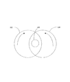
図1は、内視鏡内に組み込むことができ、検査表面上の照明源の鏡像を除去、または少なくとも大幅に低減させるために本発明のいくつかの実施形態で使用することができる偏光変調の概略的な配置を示す。 FIG. 1 illustrates a polarization modulation that can be incorporated into an endoscope and used in some embodiments of the invention to eliminate, or at least significantly reduce, the mirror image of the illumination source on the examination surface. A schematic arrangement is shown.
図1に示す例では、2つのファラデー回転子102および104が設けられている。ファラデー回転子は、ファラデー効果に基づいた偏光回転子であり、直線偏光面を回転させることが可能である。直線偏光面は、光の伝播方向に対して平行に磁界が印加されるときに回転させることができる。
In the example shown in FIG. 1, two
本発明のいくつかの実施形態によれば、時間変調偏光状態が生成され、ロックイン増幅プロセスに使用される。時間偏光変調を生成する1つの可能な方法は、たとえば、回転軸が実質上平行であるがずれている2つのファラデー回転子を使用することによって得ることができる。ファラデー回転子を異なる既知の角速度(たとえば、異なる周波数)で回転させることによって、直線偏光レーザビーム、たとえば内視鏡の照明源によって生成された照明光上に、時間偏光変調シーケンスを得ることができる。 According to some embodiments of the invention, time-modulated polarization states are generated and used in the lock-in amplification process. One possible way of producing time-polarization modulation can be obtained, for example, by using two Faraday rotators whose axes of rotation are substantially parallel but offset. By rotating the Faraday rotator at different known angular velocities (eg different frequencies), a time polarization modulation sequence can be obtained on a linearly polarized laser beam, eg the illumination light produced by the illumination source of an endoscope. ..
照明スポットの鏡像が部分的に偏光され、照明表面の非鏡像がないと考えれば、2つのファラデー回転子をロックイン増幅効果として使用して、たとえば上述したように、ファラデー回転子を操作することによって、照明表面の非鏡像から鏡像106をより良好に分離、たとえば除去、または大幅に低減させることが可能である。これは、整合された符号化−復号シーケンスが非鏡像ではなく主に鏡像に適用され、したがって互いからより良好に分離されるからである。ロックイン増幅効果において、信号を後に符号化および復号することができ、符号化−復号シーケンス間に整合がないノイズとは異なる形で、信号を増幅することを可能にする。
Given that the mirror image of the illumination spot is partially polarized and there is no non-mirror image of the illumination surface, use two Faraday rotators as a lock-in amplification effect, eg to manipulate the Faraday rotator as described above. Allows the
図2は、本発明のいくつかの実施形態に係る鏡像を除去することを目的としたファラデー回転子を有する内視鏡を示す。 FIG. 2 shows an endoscope with a Faraday rotator intended to remove a mirror image according to some embodiments of the invention.
内視鏡200、たとえばマルチコアファイバ内視鏡が示されており、細長いマルチコアファイバ202と、コントローラ220とを有する。コントローラ220は、1つまたは複数の指定の照明コア、たとえばコア204を通ってマルチコアファイバ202に沿って伝送され、内視鏡ファイバの遠位先端の前に位置する検査表面211を照明する照明ビーム、たとえばレーザビーム208を生成する照明源222と、検査表面211から反射され、複数のコア、たとえばコア206を介して光センサ224へ伝送される光210を感知する光センサ224(たとえば、光検出器)と、照明源222を制御して動作させ、光センサ224からの感知されたデータを処理し、出力デバイス228を介して出力するための画像データを生成するプロセッサ226とを含むことができる。いくつかの実施形態では、出力デバイス228は、プロセッサによって生成される画像を表示する表示デバイス、たとえばコンピュータスクリーン、または人間の目による検査の場合は光学接眼レンズとすることができる。
An
いくつかの実施形態では、照明源222は、1つまたは複数のレーザ源(場合により、狭帯域源)と、照明を改善するために最適化されたビームプロファイルを生成するように構成されたマルチコアファイバ204の遠位端にある少なくとも1つのビーム成形要素とを備えることができる。たとえば、ビームプロファイルは、空間内の均一の照明分布または矩形の均一のプロファイル(たとえば、シルクハット照明分布)を含むことができ、これは結果として得られる画像の様々なパラメータに対して、ガウス照明分布に比べて有利である。ビーム成形要素によって照明ビームを効率的に成形するために、レーザ源のコヒーレンスを使用することができる。いくつかの実施形態では、少なくとも1つのビーム成形要素を、マルチコアファイバ204の近位端に設定することができる。
In some embodiments, the
いくつかの実施形態では、照明源222は、内視鏡200による指定の治療をたとえば組織に施すように構成された1つまたは複数のレーザ治療源を備えることができる。たとえば、尿管鏡として設計された内視鏡200を使用して、腎臓結石にレーザ治療を適用することができる。
In some embodiments, the
本発明のいくつかの実施形態に係る図2に示す内視鏡の設計(ファラデー回転子なし、以下「基本設計」)、および当技術分野で知られている典型的な内視鏡の設計は、本明細書に論じる改善のいずれにも当てはまる。内視鏡の基本設計は、本明細書に論じる改善のそれぞれを別個にまたは様々な組合せで組み込むことができる。したがって、内視鏡の部分(たとえば、ファイバのみ、および/または内視鏡の他の部分)について説明するとき、これらの説明される部分は、内視鏡の基本設計ならびに他の内視鏡にも適用することができることを理解されたい。 The endoscope design shown in FIG. 2 according to some embodiments of the present invention (without a Faraday rotator, hereinafter “basic design”), and a typical endoscope design known in the art, includes: , Any of the improvements discussed herein. The basic endoscope design can incorporate each of the improvements discussed herein separately or in various combinations. Thus, when describing parts of an endoscope (eg, fiber only, and/or other parts of the endoscope), these described parts refer to the basic design of the endoscope as well as to other endoscopes. It should be appreciated that can also be applied.
本発明のいくつかの実施形態によれば、たとえば2つのファラデー回転子212および214の形で時間変調シーケンサが設けられており、ファラデー回転子212および214は、照明ビームの光路内に配置され、コントローラ220によって動作可能である。この図に示すように、ファラデー回転子は隔置することができ、たとえば一方のファラデー回転子212は、照明光導波路(光ファイバ204)からの照明ビーム208の出口にある内視鏡200の遠位端に配置することができ、他方のファラデー回転子は、光210の反射ビームが光ファイバ206から光センサ224の前に出てくる内視鏡の近位端に配置することができる。
According to some embodiments of the invention, a time modulation sequencer is provided, for example in the form of two
図3は、この例では異なる形状および/または向きの複数のコア302および304を含むマルチコアファイバ300を有する本発明のいくつかの実施形態に係るマルチコアファイバ内視鏡の横断面図を示す。この図に示す配置では、コア302は長軸306を有し、コア304は、長軸306に実質上直交する長軸308を有する。本発明のいくつかの実施形態では、典型的なコア直径は、0.8〜2ミクロン、たとえば約1ミクロンなどの範囲とすることができる。コア配置は、マルチコアファイバを部分的にのみ占有するように示されているが、他の実施形態では、コア302および304は、マルチコアファイバの断面全体を充填することができ、または断面内の1つもしくは複数の部分区間を占有することができる。これらのコアは、混合配置で配置されており、たとえばコア302は、1つのアレイで配置され、コア304は、第1のアレイに対して移動された第2のアレイで配置される。コア(またはフォトニック結晶ファイバ(PCF)、簡潔にするために、本明細書では「コア」とも呼ぶ)のそのような配置は、解像度の強化およびエネルギー処理量の増大を容易にすることができる。異なる形状を有する2つの構造(たとえば、PCFコアまたは他のコア)の混合配置(たとえば、織り合わせたアレイ配置)を提供することによって、より高解像度の伝送およびコア間のより小さいクロストークを実現することができる。提案された配置の別の利点は、青色波長が隣接コアに対して赤色より多くのクロストークを呈するため、そのような織り合わせた配置を適用することによって、分散を強化して回折を相殺し、すべての波長に対して同じクロストークを有することができ、それにより捕捉された画像に対してより良好な均一性を提供することである。追加される別の価値は、充填率がはるかに大きくなり(より多くのコアを所与の断面のファイバに閉じ込めることができる)、したがってファイバの断面積が撮像の目的でより良好に利用されることである。
FIG. 3 shows a cross-sectional view of a multicore fiber endoscope according to some embodiments of the invention having a
図4Aは、本発明のいくつかの実施形態に係る内視鏡のモノリシック撮像および照明マルチコアファイバ400を示す。
FIG. 4A illustrates an endoscope monolithic imaging and illumination
内視鏡のモノリシックファイバ400は、複数の撮像コア402を有する少なくとも1つ(または複数)の撮像マルチコア領域403と、照明コア404を有する少なくとも1つ(または複数)の照明領域405とを含むことができる。モノリシックファイバは、ポリマーから作製することができる。ファイバを通る照明のエネルギー伝送の効率を強化するために、照明領域405は、近位先端から遠位先端へ延びる中空の(空気で充填された)照明コア404(たとえば、モノリシックファイバ内の孔)を含むことができる。各照明コア404を取り囲むPCFコア406(たとえば、PCF導管のいくつかのリング、たとえばいくつかの実施形態では、3つ以上のリング)を設けることができる。いくつかの実施形態によれば、いくつかの照明チャネル(図4に示す例では4つ)がPCFコアによって取り囲まれているとき、PCFコアは空気で充填された照明コア内に照明光を閉じ込める働きをするため、ファイバ内に大幅な照明損失は存在しない。本発明のいくつかの実施形態では、照明コアの直径は約100〜200ミクロンであり、撮像コアの直径は約1ミクロンであり、PCFコアは波長(通過する光に対する)以下であり、たとえば0.2ミクロンである。
The endoscope
いくつかの実施形態では、ファイバの近位端で顕微鏡的拡大を得ることができ、したがって反射された照明を収集してそれを光センサ(たとえば、カメラ)へ伝送する照明領域405および撮像領域403は、照明モジュールならびにカメラがどちらも同じ先端(ファイバの遠位先端)に位置するにもかかわらず、いかなる複雑な位置合わせ問題もなく、空間的に分離することができる。Yカプラを使用して、照明源(図2の222)からの光ビームをいくつか(たとえば、4つ)の空間的に分離された照明点源に分割することができる。
In some embodiments, a microscopic magnification can be obtained at the proximal end of the fiber, thus collecting the reflected illumination and transmitting it to a photosensor (eg, camera)
図4Bは、本発明のいくつかの実施形態に係る複数の金属被覆コア452を有するマルチコアファイバ内視鏡450の横断面図を示す。隣接コアのクロストークに関連することのある解像度およびエネルギー伝送効率の問題を克服するために、各コア458(たとえば、撮像コア、照明コア)を、薄い金属被覆456(たとえば、約150〜300ナノメートル、たとえば200nmの厚さ)で被覆することができる。典型的には、今まで、マルチコアファイバ内のコア間のピッチは約3.6ミクロンであり、小さいコアの直径は約0.9ミクロンである。金属被覆を提供することによって、コアの密度を増大させることができ、その結果、断面積当たりより多くのコアを得ることができ、したがってより高い撮像解像度を得ることができる。本発明のいくつかの実施形態によれば、隣接コアのピッチは、2ミクロンより小さく、たとえば約1ミクロンとすることができる。被覆は鏡のように作用し、コア間のクロストークを防止する。光学モードは、コアのみを通って進み、クラッドの材料内に跡が残らないように閉じ込めることができる。クラッドの材料は典型的にコアの材料より多く吸収するため、この配置により伝送損失を低減させることができる。そのようなマルチコアファイバの製作は、各ロッドを金属被覆(たとえば、管)で被覆し、次いで当技術分野で知られているように母材を構築し、次いで当技術分野で知られているようにこの母材を引き抜き加工することを含むことができる。本発明の目的で、「約」と記載するとき、これは実際の測定値から10パーセントの逸脱を包含することを意味したものである。
FIG. 4B shows a cross-sectional view of a
図5Aは、高解像度撮像を得るための本発明のいくつかの実施形態に係る内視鏡に対するマルチコアファイバ500を示す。
FIG. 5A shows a
患者の体腔内の検査表面211を撮像するように設計されたファイバ500の遠位先端には、焦点距離Fをあけてフーリエ変換レンズ502を配置することができ、ファイバ500の近位先端には、近位先端から距離Fをあけて逆フーリエ変換レンズ504を配置することができる。照明光ビームがコヒーレントレーザ源によって生成されるため、そのような変換(フーリエ変換)を実行することが可能である。この配置により、内視鏡のマルチコアファイバ500のコア501は、フーリエ領域のまばらな圧縮サンプリングを実行する。次いで、光検出器506(たとえば、カメラ)に近い撮像レンズ504が逆フーリエを実行し、したがってコアはフーリエ面をサンプリングし、実際の画像を伝送しないため、画像をデジタルで強化する必要(たとえば、撮像コアによって得られるコア画像データ間の補間)なく、高解像度画像を得ることができる。そのような配置は、まばらなサンプリングを介して実現されるすべての光学補間を容易にすることができ、まばらなサンプリング自体は、マルチコアファイバ500の構造を介して実現される。
A
本発明のいくつかの実施形態では、たとえばファイバが十分に研磨されておらず、それによりランダム位相が導入された場合、ファイバの遠位先端で光撮像のためにレンズ502を使用することができる。レーザ源510を使用して、光検出器506を参照照明ビーム512で照明し、デジタルフーリエホログラフィック記録(コヒーレントレーザ照明が使用されるため)を実現することができ、それによりデジタル復号のみによって位相および高解像度物体の構造を容易にすることができる。
In some embodiments of the invention, a
図5Bは、検査表面からマルチコアファイバ内へ反射される光の光路上に配置された複数(たとえば、4つ)のPCFを備える光学素子520(万華鏡と同様)を使用して高解像度撮像を得るための本発明のいくつかの実施形態に係る内視鏡に対するマルチコアファイバを示す。 FIG. 5B shows high resolution imaging using an optical element 520 (similar to a kaleidoscope) with multiple (eg, four) PCFs placed in the optical path of light reflected from the inspection surface into the multicore fiber. 6 illustrates a multi-core fiber for an endoscope according to some embodiments of the present invention.
4つのPCFを含む光学素子520を使用するため、フーリエ変換する必要のある検査表面211はエルミート対称になり、これはそのフーリエ変換が本物であることを意味する。そのようにフーリエ変換された検査表面211は、検出器506が強度画像のみを捕捉するため、いかなる位相歪みにもかかわらず、マルチコアファイバ500を介して伝達することができる。
Because of the use of the
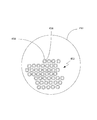
図6は、本発明のいくつかの実施形態に係る白色光照明コアを有する内視鏡の矩形マルチコアファイバ600の横断面図を示す。
FIG. 6 shows a cross-sectional view of a rectangular
本発明のいくつかの実施形態によれば、矩形マルチコアファイバ600は、検査表面から反射された光を伝達するための撮像領域を含み、撮像領域には複数の撮像コア604が位置する。本発明のいくつかの実施形態によれば、照明配置は、マルチスペクトル撮像(狭帯域撮像(NBI)など)の簡単な実現を得ることを可能にする異なる波長を有する1組のレーザを含む。1組の離散波長によるこのタイプの照明に伴う問題は、良好な全域を得ることができるが、スペクトル内の孔が特有のタイプの組織に対して劣悪な検出品質をもたらす可能性があることである。これを解決するために、たとえば撮像領域の周辺部内に非常に高い開口数(NA)を有する中空のPCFコア606を設けることができ、蛍光染料(液体)でそれを充填することができる。染料は容器610内に収容することができ、容器610から送達ライン612(この図にはいくつかのみを示す)を介してコア606(たとえば、所定の直径608を有する)内へ染料を送達することができる。染料は、照明モジュールの離散レーザで照射および励起されるように構成することができる溶液混合物になるように選択することができる。蛍光染料は、長い照明PCFコアに沿って、マルチスペクトル撮像/感知に使用されるレーザの離散波長に加えて、連続白色光照明スペクトルを生成することができる。
According to some embodiments of the present invention, rectangular
図7は、本発明のいくつかの実施形態に係るマルチコアファイバを有する内視鏡内に含むことができる撮像コア間のクロストークを抑制するために周辺コアを有するいくつかの撮像コアの横断面図を示す。 FIG. 7 is a cross-section of some imaging cores with peripheral cores to suppress crosstalk between imaging cores that can be included in an endoscope with multi-core fibers according to some embodiments of the invention. The figure is shown.
いくつかの実施形態によれば、マルチコアファイバの撮像解像度を強化する方法の1つは、撮像領域内のコア702の密度をより高くすることである。しかし、コア間のクロストークを増大させることなく、撮像コアのこの密度を増大させることが望ましい。起こりうるクロストークを抑制するために、撮像コアのそれぞれの周りに複数の周辺コア704を追加することによって、コアとその周辺との間の屈折率の差を人工的に増大させることができる。周辺コアは中空とすることができ、空気で充填することができる。そのようにして、クラッド材料の屈折率と空気(屈折率1)との間で平均屈折率を平均化することができる。周辺コアの直径は、好ましくは、撮像コアを通過する予想される光の光波長より小さくするべきである。周辺コアは、母材内に穿孔されるときは大きくてよいが、引き抜き加工後は、撮像コアを通過する反射光の光波長より小さくなるように寸法を減らすことができる。そのようにして、クロストークを増大させることなく、撮像コアをともにより近くに配置することができる。
According to some embodiments, one way to enhance the imaging resolution of multi-core fibers is to have a higher density of
ポリマーファイバの伝送はそれほど効率的ではないため、十分な量の反射光を光検出器に到達させるためには、非常に強い照明を必要とすることがある。これは、放射安全性上の問題を生じさせることがある。 Since the transmission of polymer fibers is not very efficient, very strong illumination may be required to get a sufficient amount of reflected light to reach the photodetector. This can cause radiative safety issues.
図8は、本発明のいくつかの実施形態に係るレーザ光を使用する内視鏡検査における向上された放射安全性のための方法800を示す。方法800は、内視鏡のマルチコアファイバの撮像コア内へ増幅材料(たとえば、Nd:YAG、ドープされたエルビウムなど)を埋め込むことと、検査表面から反射され撮像コアを通過する光を増幅するように構成された所定の波長のレーザ光によって撮像コアを励起することとを含むことができる。収集された光が増幅されるため、CMOSセンサにとって十分な感度を提供するために撮像ファイバ内で必要とされる光子をより少なくすることができる。収集される光がより少ないということは、より少ない光で組織を照明することを意味し、これにより検査される組織に対して安全条件を与えることができる。
FIG. 8 illustrates a
増幅材料が埋め込まれた内視鏡を使用する利点の1つは、これにより、多種多様な医療応用例に対してより長い内視鏡の使用を可能にすることができることである。 One of the advantages of using an endoscope with an embedded amplifying material is that it can allow longer endoscope use for a wide variety of medical applications.
図9は、本発明のいくつかの実施形態に係る内視鏡検査における光学ズームのための方法1000を示す。
FIG. 9 illustrates a
方法1000は、レーザ源を使用して、内視鏡マルチコアファイバの遠位先端に位置するレンズの設計に関して事前定義された曲率の球形波面を有する、検査表面を照明するための照明ビームを生成すること1002を含むことができる。方法1000は、検査表面の画像を光学的に拡大または縮小するように、レンズの設計に対する球形波長の曲率を変化させること1004をさらに含むことができる。
The
レーザ照明で投影することによる光学ズームを実現するために、内視鏡の先端におけるレンズ設計に整合された球形波面を設けることができる。照明ビームの曲率を変化させることで、光学ズーム倍率が変化する。 A spherical wavefront matched to the lens design at the tip of the endoscope can be provided to achieve optical zoom by projecting with laser illumination. The optical zoom magnification is changed by changing the curvature of the illumination beam.
図10は、本発明のいくつかの他の実施形態に係る内視鏡検査における光学ズームのための方法1100を示す。
FIG. 10 illustrates a
この方法は、マルチコアファイバの遠位先端に焦点距離を有する第1のフーリエレンズを有する検査表面を検査する内視鏡に好適である。方法1100は、近位先端と光検出器との間に配置されたマルチコアファイバの近位先端に調整可能な焦点距離を有する第2のフーリエレンズを提供すること1010と、検査表面の画像を光学的に拡大または縮小するように、第2のフーリエレンズの調整可能な焦点距離を調整すること1012とを含むことができる。
This method is suitable for an endoscope that inspects an inspection surface having a first Fourier lens with a focal length at the distal tip of a multicore fiber. The
変倍(光学ズーム)は、内視鏡の遠位先端にある固定されたレンズの焦点距離と近位端にある調整可能な焦点距離との間の比に等しくすることができる。 Magnification (optical zoom) can be equal to the ratio between the focal length of the fixed lens at the distal tip of the endoscope and the adjustable focal length at the proximal end.
図11は、本発明のいくつかの他の実施形態に係る2つの光学ズームされた画像を提供する内視鏡のマルチコアファイバを示す。 FIG. 11 illustrates a multi-core fiber of an endoscope that provides two optically zoomed images according to some other embodiments of the invention.
この実施形態では、ファイバの近位端にあるレンズ1200は、λ1(第1の波長)に対する焦点距離およびλ2(第2の波長)に対する焦点距離という2つの焦点距離を有することができ、したがってこれらの焦点距離のうちの一方がフーリエ変換を実行し、他方の焦点距離が光撮像を実行する。2つの波長は、検出器506の前に位置する格子1202によって分離することができる。そのようにして、検出器の半分1204に、たとえば低解像度および良好な視野で、光学画像が投影され、検出器の別の部分1206に、たとえば高解像度および制限された視野で、フーリエ変換画像が投影される。そのようにして、λ多重化による光学ズームを得ることができる。
In this embodiment, the
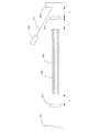
図12Aは、本発明のいくつかの実施形態に係るサンプリング能力を有するマルチコアファイバ内視鏡1200を観察モードで示す。マルチコアファイバ内視鏡1200は、複数の撮像コアおよび複数の照明コアを有するマルチコアファイバ1202を含む。観察モードで、複数の照明コア(簡潔にするために、2つの照明コア1205、1207のみを示す)を使用して、光1206を撮像面211へ誘導する。複数の撮像コア(簡潔にするために、1つの撮像コア1203のみを示す)を使用して、撮像面211から反射された光1208を撮像センサ1212へ誘導する。ビーム偏向器1210(たとえば、ビームスプリッタ)を使用して、反射光ビーム1208を撮像センサ1212(たとえば、CMOS検出器)へそらすことができる。マルチコアファイバ1204は、遮蔽スリーブ1202内に挿入される。マルチコアファイバ1204の近位端でビーム偏向器1210に結合された内視鏡の近位端に、プランジャ1214などの遮蔽スリーブ内でマルチコアファイバを前進および後退させる機構を設けることができる。
FIG. 12A illustrates a viewing mode of a
図12Bは、本発明のいくつかの実施形態に係るサンプリング能力を有するマルチコアファイバ内視鏡をサンプリングモードで示す。簡潔にするために、照明コアおよび撮像コアは示されていない。サンプリングモードで、マルチコアファイバ1204の遠位先端1216は、サンプリングされる組織面211に対向したとき、たとえばプランジャ1214を押すことによって、遮蔽スリーブ1202から外へたとえば数ミリメートル前進され、したがって先端1216を組織面211に接触させることができる。したがって、たとえば組織細胞、ならびに表面上に見られることのある液体または他の材料などの分析のためのサンプルが、マルチコアファイバ1204の先端1216に付着することができる。マルチコアファイバ1204は、表面に係合した後、たとえばプランジャ1214を引っ張ることによって、遮蔽スリーブ1202内へ後退させることができ、したがって内視鏡が患者の体外へ抜き出されたとき、得られたサンプルは先端1216上にそのまま残る。
FIG. 12B illustrates a multi-core fiber endoscope with sampling capability in sampling mode according to some embodiments of the present invention. For simplicity, the illumination and imaging cores are not shown. In the sampling mode, the
撮像ファイバ先端がその機械的ナビゲーションシールドから数ミリメートル出て、次いで再び入ることを可能にすることで、撮像ファイバ先端を体内の液体/組織へ挿入し、それらの液体/組織のサンプルを取り出すことが可能になり、後にこの組織に対する生体検査を行うことが可能になる。 By allowing the imaging fiber tip to exit the mechanical navigation shield a few millimeters and then re-enter, it is possible to insert the imaging fiber tip into a fluid/tissue in the body and remove those fluid/tissue samples. It becomes possible, and it becomes possible to perform a biopsy on this tissue later.
この生体検査に関連する能力はまた、撮像センサの代わりに分光計(たとえば、ラマン分光計)を使用することによって、異なる手法で実現することができ、分光計は、照明ファイバレーザと協働するとき、サンプルの「非接触生体検査」分析を実行するのに好適なラマン分光法の実現を可能にすることができる。 This biopsy related capability can also be achieved in different ways by using a spectrometer (eg, a Raman spectrometer) instead of an imaging sensor, which cooperates with an illuminating fiber laser. At times, it may enable the realization of Raman spectroscopy suitable for performing "contactless biopsy" analysis of samples.
図13は、本発明のいくつかの実施形態に係る内視鏡検査において得られる画像の解像度を改善する方法を示す。 FIG. 13 illustrates a method for improving the resolution of images obtained in endoscopy according to some embodiments of the invention.
方法1300は、複数の異なる波長の赤色、複数の異なる波長の緑色、および複数の異なる波長の青色によって検査表面を照明すること1302を含むことができる。方法1300はまた、光検出器によって、複数の異なる波長の赤色、複数の異なる波長の緑色、および複数の異なる波長の青色によって検査表面から反射された光の画像データを収集すること1304を含むことができる。方法1300はまた、収集された画像データから画像を構築すること1306を含むことができる。
本発明のいくつかの実施形態は、波長多重化を使用して、たとえばいくつかの波長の赤色、緑色、および青色を送り、コアごとに各色に対するいくつかの波長を収集することによって撮像の解像度を改善することを含むことができ、次いで色ごとに放たれる波長の数に応じて解像度が強化される。解像度の強化は、1組の色のうちの各色(赤色、緑色、または青色)が検査される物体の異なる空間位置へ進み、したがって色と空間位置との間の参照表が生成される場合に得られる。そのようにして、分光情報を検査することで、マッピングの使用に続いて空間情報を与えることができる。 Some embodiments of the present invention use wavelength multiplexing, for example, by sending several wavelengths of red, green, and blue, and by collecting several wavelengths for each color on a per core basis, the resolution of the imaging. , And then the resolution is enhanced depending on the number of wavelengths emitted per color. Resolution enhancement proceeds when each color (red, green, or blue) of a set of colors goes to a different spatial position of the object being inspected, and thus a look-up table between color and spatial position is generated. can get. In that way, examining the spectroscopic information can provide spatial information following the use of the mapping.
図14は、本発明のいくつかの実施形態に係る内視鏡検査における画像解像度を改善する光学ズームのための方法を示す。 FIG. 14 illustrates a method for optical zoom to improve image resolution in endoscopy according to some embodiments of the present invention.
方法1400は、検査表面から反射され、複数の撮像コアを含むマルチコアファイバを通過した光の光路上に2焦点レンズを提供すること1402を含むことができる。
方法1400はまた、2焦点レンズの焦点距離のそれぞれを較正に使用すること1404と、較正に基づいて、光検出器上で内視鏡によって得られた正規画像および拡大画像という2つの重畳画像を分離すること1406とを含むことができる。
The
方法1400はまた、拡大画像をデジタルで縮小すること1408と、縮小された後に拡大画像からの画像データを正規画像に追加して、より高解像度の正規画像を得ること1410とを含むことができる。
The
各焦点距離は、正規画像および拡大画像という2つの重畳画像を分離するために較正として使用されるいくつかのゼロ点を空間内に有する。分離(ブラインド源分離と同様)後、拡大画像をデジタルで縮小し、正規画像に追加して、視野の中心部分でより高い解像度を得ることができる。 Each focal length has a number of zero points in space that are used as a calibration to separate the two superimposed images, the regular image and the magnified image. After separation (similar to blind source separation), the magnified image can be digitally reduced and added to the regular image to obtain higher resolution in the central part of the field of view.
本発明のいくつかの実施形態は、システム、方法、またはコンピュータプログラム製品の形態で実施することができる。同様に、いくつかの実施形態は、ハードウェア、ソフトウェア、またはこれら両方の組合せとして実施することができる。いくつかの実施形態は、1つまたは複数の非一時的コンピュータ可読媒体上に保存されたコンピュータプログラム製品として、非一時的コンピュータ可読媒体上で実施されるコンピュータ可読プログラムコードの形態で実施することができる。そのような非一時的コンピュータ可読媒体は、実行されると例に係る方法ステップをプロセッサに実行させる命令を含むことができる。いくつかの例では、コンピュータ可読媒体上に記憶される命令は、インストールされたアプリケーションおよびインストールパッケージの形態とすることができる。 Some embodiments of the invention may be implemented in the form of a system, method, or computer program product. Similarly, some embodiments may be implemented as hardware, software, or a combination of both. Some embodiments may be implemented in the form of computer-readable program code embodied on non-transitory computer-readable media as a computer program product stored on one or more non-transitory computer-readable media. it can. Such non-transitory computer-readable media may include instructions that, when executed, cause a processor to perform example method steps. In some examples, the instructions stored on the computer-readable medium may be in the form of installed applications and installation packages.
そのような命令は、たとえば、1つまたは複数のプロセッサによってロードし、実行することができる。 Such instructions may be loaded and executed by one or more processors, for example.
たとえば、コンピュータ可読媒体は、非一時的コンピュータ可読記憶媒体とすることができる。非一時的コンピュータ可読記憶媒体は、たとえば、電子、光学、磁気、電磁、赤外、もしくは半導体のシステム、装置、もしくはデバイス、またはこれらの任意の組合せとすることができる。 For example, the computer-readable medium may be a non-transitory computer-readable storage medium. A non-transitory computer readable storage medium can be, for example, an electronic, optical, magnetic, electromagnetic, infrared, or semiconductor system, device, or device, or any combination thereof.
コンピュータプログラムコードは、任意の好適なプログラミング言語で書くことができる。プログラムコードは、単一のコンピュータシステム上または複数のコンピュータシステム上で実行することができる。 The computer program code can be written in any suitable programming language. The program code can execute on a single computer system or multiple computer systems.
いくつかの実施形態について、様々な実施形態に係る方法、システム、およびコンピュータプログラム製品を示す流れ図および/またはブロック図を参照して上記に説明した。 Some embodiments have been described above with reference to flowchart illustrations and/or block diagrams of methods, systems and computer program products according to various embodiments.
本明細書に論じた様々な実施形態の特徴は、本明細書に論じた他の実施形態とともに使用することもできる。実施形態の上記の説明は、例示および説明の目的で提示されている。上記の説明は、開示した厳密な形態に対して網羅的または限定的であることを意図したものではない。上記の教示に照らして、多くの修正形態、変形形態、置換え、変更形態、および均等物が可能であることを、当業者には理解されたい。したがって、添付の特許請求の範囲は、本発明の本当の趣旨の範囲内に入るそのようなすべての修正形態および変形形態を包含することを意図したものであることを理解されたい。 Features of the various embodiments discussed herein may also be used with the other embodiments discussed herein. The above description of the embodiments is presented for purposes of illustration and description. The above description is not intended to be exhaustive or limiting to the precise form disclosed. Those skilled in the art will appreciate that many modifications, variations, substitutions, changes and equivalents are possible in light of the above teachings. Therefore, it is to be understood that the appended claims are intended to cover all such modifications and variations that fall within the true spirit of the invention.
Claims (29)
光センサと、
マルチコアファイバであって、
検査すべき表面の照明のための少なくとも1つのコアであって、前記少なくとも1つのコアを通って前記照明源から前記ファイバの遠位端へ前記照明ビームを伝達する少なくとも1つのコア、および
前記表面から反射された光を前記光センサへ伝達する複数のコア
を備えるマルチコアファイバと、
前記照明ビームの鏡像を前記表面の画像から分離する時間変調シーケンサと、
前記光センサからの感知されたデータを処理して前記表面の前記画像を生成するプロセッサと
を備える内視鏡。 An illumination source that produces a coherent laser illumination beam;
An optical sensor,
A multi-core fiber,
At least one core for illumination of a surface to be inspected, the at least one core transmitting the illumination beam from the illumination source to the distal end of the fiber through the at least one core; A multi-core fiber having a plurality of cores for transmitting the light reflected from the optical sensor to the optical sensor,
A time-modulated sequencer that separates a mirror image of the illumination beam from an image of the surface;
A processor for processing sensed data from the light sensor to generate the image of the surface.
前記マルチコアファイバが、
検査すべき表面の照明のための少なくとも1つの中空コアであって、前記少なくとも1つのコアを通って照明源から前記ファイバの遠位端へ照明ビームを伝達する少なくとも1つの中空コア、および前記少なくとも1つの中空コア内に前記照明ビームを閉じ込めるように前記少なくとも1つの中空コアのそれぞれを取り囲む複数のコアを含む照明領域と、
前記表面から反射された光を光センサへ伝達する複数のコアを含む撮像領域とを備える、内視鏡。 An endoscope including a multi-core fiber,
The multi-core fiber,
At least one hollow core for illumination of a surface to be inspected, the at least one hollow core transmitting an illumination beam through the at least one core from an illumination source to a distal end of the fiber; and An illumination region comprising a plurality of cores surrounding each of said at least one hollow core so as to confine said illumination beam within one hollow core;
An endoscope including: an imaging region including a plurality of cores that transmit light reflected from the surface to an optical sensor.
マルチコアファイバであって、
検査表面から反射された光を前記光センサへ伝達する複数のコア、
前記マルチコアファイバの遠位先端から所定の距離をあけて配置された、前記表面から反射された前記光でフーリエ変換を実行するレンズ、および
前記マルチコアファイバの近位先端から所定の距離をあけて配置された、前記マルチコアファイバの近位先端から出た後に前記表面から反射された前記光で逆フーリエ変換を実行するレンズ
を備えるマルチコアファイバと、
前記光センサからの感知されたデータを処理して前記表面の画像を生成するプロセッサと
を備える内視鏡。 An optical sensor,
A multi-core fiber,
A plurality of cores for transmitting light reflected from the inspection surface to the photosensor,
A lens disposed a predetermined distance from the distal tip of the multicore fiber to perform a Fourier transform on the light reflected from the surface, and a distance spaced from the proximal tip of the multicore fiber. A multi-core fiber that performs an inverse Fourier transform on the light reflected from the surface after exiting the proximal tip of the multi-core fiber;
A processor for processing the sensed data from the light sensor to generate an image of the surface.
前記マルチコアファイバが、
検査すべき表面の照明のための少なくとも1つの撮像コアであって、前記少なくとも1つのコアを通って照明源から前記ファイバの遠位端へ照明ビームを伝達する少なくとも1つの撮像コアを含む照明領域と、
前記表面から反射された光を光センサへ伝達する複数のコアを含む撮像領域と、
蛍光染料を収容する染料容器であって、前記染料に照射して連続白色光照明スペクトルを生成することを可能にするように、前記1つの撮像コア内へ前記染料を供給するように構成された染料容器とを備える、内視鏡。 An endoscope including a multi-core fiber,
The multi-core fiber,
An illumination region including at least one imaging core for illumination of a surface to be inspected, the at least one imaging core transmitting an illumination beam through an illumination source from an illumination source to a distal end of the fiber. When,
An imaging region including a plurality of cores that transmit light reflected from the surface to a photosensor;
A dye container containing a fluorescent dye, the dye container configured to provide the dye into the one imaging core to enable the dye to be illuminated to produce a continuous white light illumination spectrum. An endoscope including a dye container.
前記マルチコアファイバが、
表面から反射された光を光センサへ伝達する複数の撮像コアを含む撮像領域と、
前記複数の撮像コアのそれぞれの周りに位置する複数の周辺コアとを備え、前記周辺コアのそれぞれの直径が、前記撮像コアを通過することが予想される反射光の波長より小さい、内視鏡。 An endoscope including a multi-core fiber,
The multi-core fiber,
An imaging region that includes a plurality of imaging cores that transmits the light reflected from the surface to an optical sensor;
An endoscope comprising: a plurality of peripheral cores located around each of the plurality of imaging cores, each diameter of the peripheral cores being less than a wavelength of reflected light expected to pass through the imaging cores. ..
内視鏡のマルチコアファイバの撮像コア内へ増幅材料を埋め込むことと、
検査表面から反射され前記撮像コアを通過する光を増幅するように構成された所定の波長のレーザ光によって前記撮像コアを励起することとを含む方法。 A method for improved radiation safety in endoscopy using laser light, comprising:
Embedding an amplifying material in the imaging core of the multicore fiber of the endoscope;
Exciting the imaging core with laser light of a predetermined wavelength configured to amplify light reflected from the inspection surface and passing through the imaging core.
レーザ源を使用して、内視鏡マルチコアファイバの遠位先端に位置するレンズの設計に関して事前定義された曲率の球形波面を有する、検査表面を照明するための照明ビームを生成することと、
前記検査表面の画像を光学的に拡大または縮小するように、前記レンズの前記設計に対する前記球形波長の前記曲率を変化させることとを含む方法。 A method for optical zoom in endoscopy, comprising:
Using a laser source to generate an illumination beam for illuminating an inspection surface having a spherical wavefront of curvature predefined for the design of a lens located at the distal tip of an endoscopic multicore fiber;
Varying the curvature of the spherical wavelength for the design of the lens so as to optically magnify or reduce the image of the inspection surface.
前記マルチコアファイバの近位先端と光検出器との間に配置された前記近位先端に調整可能な焦点距離を有する第2のフーリエレンズを提供することと、
前記検査表面の画像を光学的に拡大または縮小するように、前記第2のフーリエレンズの前記調整可能な焦点距離を調整することとを含む方法。 A method for optical zooming when using an endoscope to inspect an inspection surface, the endoscope comprising a first Fourier lens having a focal length at a distal tip of a multicore fiber. , The method is
Providing a second Fourier lens with an adjustable focal length at the proximal tip disposed between the proximal tip of the multicore fiber and a photodetector;
Adjusting the adjustable focal length of the second Fourier lens to optically magnify or reduce the image of the inspection surface.
複数の異なる波長の赤色、複数の異なる波長の緑色、および複数の異なる波長の青色によって検査表面を照明することと、
光検出器によって、前記複数の異なる波長の赤色、前記複数の異なる波長の緑色、および前記複数の異なる波長の青色によって前記検査表面から反射された光の画像データを収集することと、
前記収集された画像データから画像を構築することとを含む方法。 A method of improving the resolution of an image obtained using an endoscope having a multi-core fiber, comprising:
Illuminating the inspection surface with a plurality of different wavelengths of red, a plurality of different wavelengths of green, and a plurality of different wavelengths of blue;
Collecting image data of light reflected from the inspection surface by the plurality of different wavelengths of red, the plurality of different wavelengths of green, and the plurality of different wavelengths of blue by a photodetector;
Constructing an image from the collected image data.
検査表面から反射され、複数の撮像コアを含むマルチコアファイバを通過した光の光路上に2焦点レンズを提供することと、
前記2焦点レンズの焦点距離のそれぞれを較正に使用することと、
前記較正に基づいて、光検出器上で内視鏡によって得られた正規画像および拡大画像という2つの重畳画像を分離することと、
前記拡大画像をデジタルで縮小することと、
縮小された後に前記拡大画像からの画像データを前記正規画像に追加して、より高解像度の正規画像を得ることとを含む方法。 A method for optical zoom to improve image resolution in endoscopy, comprising:
Providing a bifocal lens on the optical path of light reflected from the inspection surface and passing through a multi-core fiber including a plurality of imaging cores;
Using each of the focal lengths of the bifocal lens for calibration;
Separating two superimposed images, a normal image and a magnified image obtained by the endoscope on the photodetector, based on the calibration;
Digitally reducing the enlarged image;
Adding image data from the magnified image to the regular image after being reduced to obtain a higher resolution regular image.
前記マルチコアファイバが、
表面から反射された光を光センサへ伝達する複数の撮像コアを備え、各コアが金属被覆によって被覆される、内視鏡。 An endoscope including a multi-core fiber,
The multi-core fiber,
An endoscope comprising a plurality of imaging cores for transmitting light reflected from a surface to an optical sensor, each core being covered by a metal coating.
前記マルチコアファイバが挿入される遮蔽スリーブと、
前記マルチコアファイバの遠位先端を抜き出して前記表面に接触させ、分析のためのサンプルを収集し、前記遠位先端を前記遮蔽スリーブ内へ後退させることを可能にするように、前記遮蔽スリーブ内で前記マルチコアファイバを前進および後退させる機構と
を備える内視鏡。 A multicore fiber having a distal end and a proximal end, the one or more illumination cores transmitting light from the proximal end from the distal end to illuminate an interior surface of a patient to be observed, and A multi-core fiber having one or more imaging cores for transmitting light reflected from an inner surface into the imaging cores from the distal end to the proximal end;
A shielding sleeve into which the multi-core fiber is inserted,
Within the shielding sleeve to allow the distal tip of the multicore fiber to be withdrawn and brought into contact with the surface, collecting a sample for analysis and retracting the distal tip into the shielding sleeve. A mechanism for advancing and retracting the multi-core fiber.
Applications Claiming Priority (2)
| Application Number | Priority Date | Filing Date | Title |
|---|---|---|---|
| US16/221,593 US20200187766A1 (en) | 2018-12-17 | 2018-12-17 | Enhanced multicore fiber endoscopes |
| US16/221,593 | 2018-12-17 |
Publications (2)
| Publication Number | Publication Date |
|---|---|
| JP2020096834A true JP2020096834A (en) | 2020-06-25 |
| JP2020096834A5 JP2020096834A5 (en) | 2022-12-20 |
Family
ID=71071061
Family Applications (1)
| Application Number | Title | Priority Date | Filing Date |
|---|---|---|---|
| JP2019224599A Pending JP2020096834A (en) | 2018-12-17 | 2019-12-12 | Enhanced multicore fiber endoscopes |
Country Status (2)
| Country | Link |
|---|---|
| US (2) | US20200187766A1 (en) |
| JP (1) | JP2020096834A (en) |
Cited By (1)
| Publication number | Priority date | Publication date | Assignee | Title |
|---|---|---|---|---|
| US11480317B2 (en) | 2020-09-29 | 2022-10-25 | Panasonic Intellectual Property Management Co., Ltd. | Light source device with sensor for detecting anomaly in wavelength converting member |
Families Citing this family (3)
| Publication number | Priority date | Publication date | Assignee | Title |
|---|---|---|---|---|
| EP3654824A4 (en) | 2017-07-17 | 2021-04-21 | Z Square Ltd. | Enhancing imaging by multicore fiber endoscopes |
| DE102020132454B3 (en) * | 2020-12-07 | 2021-11-25 | Karl Storz Se & Co. Kg | Endoscopic device and method for checking the identity of a component of an endoscopic device |
| CN114176492A (en) * | 2022-01-05 | 2022-03-15 | 深圳迈塔兰斯科技有限公司 | Endoscope probe, endoscope and scanning control method thereof |
-
2018
- 2018-12-17 US US16/221,593 patent/US20200187766A1/en not_active Abandoned
-
2019
- 2019-12-12 JP JP2019224599A patent/JP2020096834A/en active Pending
-
2022
- 2022-12-14 US US18/080,844 patent/US20230110978A1/en active Pending
Cited By (1)
| Publication number | Priority date | Publication date | Assignee | Title |
|---|---|---|---|---|
| US11480317B2 (en) | 2020-09-29 | 2022-10-25 | Panasonic Intellectual Property Management Co., Ltd. | Light source device with sensor for detecting anomaly in wavelength converting member |
Also Published As
| Publication number | Publication date |
|---|---|
| US20200187766A1 (en) | 2020-06-18 |
| US20230110978A1 (en) | 2023-04-13 |
Similar Documents
| Publication | Publication Date | Title |
|---|---|---|
| US20240049956A1 (en) | Illumination sources for multicore fiber endoscopes | |
| JP6770109B2 (en) | Omnidirectional visual device | |
| JP2020096834A (en) | Enhanced multicore fiber endoscopes | |
| US9871948B2 (en) | Methods and apparatus for imaging with multimode optical fibers | |
| CN101365375B (en) | Method and apparatus for optical imaging via spectral encoding | |
| US8585587B2 (en) | Determining phase variation of light in an endoscope | |
| KR102588057B1 (en) | Optical systems and methods | |
| US8705184B2 (en) | Multi-path, multi-magnification, non-confocal fluorescence emission endoscopy apparatus and methods | |
| US20130071077A1 (en) | Endoscope connector method and apparatus | |
| JP2023055872A (en) | Enhancing imaging by multicore fiber endoscopes | |
| EP1244927B1 (en) | Methods and apparatus for imaging using a light guide bundle and a spatial light modulator | |
| US20130324858A1 (en) | Multi-path, multi-magnification, non-confocal fluorescence emission endoscopy apparatus and methods | |
| KR20120072757A (en) | Endoscopic spectral domain optical coherence tomography system based on optical coherent fiber bundle | |
| KR20210093245A (en) | Multimode waveguide imaging | |
| JP2020096834A5 (en) | ||
| WO2019015437A1 (en) | Tomographic endo-micro-spectroscopy device | |
| WO2018116302A1 (en) | Illumination sources for multicore fiber endoscopes | |
| Choi et al. | Fourier holographic endoscopy for label-free imaging through a narrow and curved passage | |
| WO2019015436A1 (en) | Tomographic endo-microscopy device | |
| Oh et al. | Review of endomicroscopic imaging with coherent manipulation of light through an ultrathin probe | |
| Pacheco et al. | Optics of Biomedical Instrumentation | |
| Cha | FIBER-OPTIC BUNDLE FLUORESCENCE MICROSCOPY FOR FUNCTIONAL BRAIN ACTIVITY MAPPING |
Legal Events
| Date | Code | Title | Description |
|---|---|---|---|
| A521 | Request for written amendment filed |
Free format text: JAPANESE INTERMEDIATE CODE: A523 Effective date: 20221212 |
|
| A621 | Written request for application examination |
Free format text: JAPANESE INTERMEDIATE CODE: A621 Effective date: 20221212 |
|
| A977 | Report on retrieval |
Free format text: JAPANESE INTERMEDIATE CODE: A971007 Effective date: 20231030 |
|
| A131 | Notification of reasons for refusal |
Free format text: JAPANESE INTERMEDIATE CODE: A131 Effective date: 20231114 |
|
| A601 | Written request for extension of time |
Free format text: JAPANESE INTERMEDIATE CODE: A601 Effective date: 20240207 |