JP2020049179A - Vibration stimulator - Google Patents
Vibration stimulator Download PDFInfo
- Publication number
- JP2020049179A JP2020049179A JP2018184665A JP2018184665A JP2020049179A JP 2020049179 A JP2020049179 A JP 2020049179A JP 2018184665 A JP2018184665 A JP 2018184665A JP 2018184665 A JP2018184665 A JP 2018184665A JP 2020049179 A JP2020049179 A JP 2020049179A
- Authority
- JP
- Japan
- Prior art keywords
- finger
- support member
- palm
- vibration
- shaft
- Prior art date
- Legal status (The legal status is an assumption and is not a legal conclusion. Google has not performed a legal analysis and makes no representation as to the accuracy of the status listed.)
- Pending
Links
- 230000004936 stimulating effect Effects 0.000 claims description 40
- 238000003780 insertion Methods 0.000 claims description 8
- 230000037431 insertion Effects 0.000 claims description 8
- 230000000638 stimulation Effects 0.000 claims description 7
- 241000905957 Channa melasoma Species 0.000 abstract 1
- 210000001142 back Anatomy 0.000 abstract 1
- 230000002401 inhibitory effect Effects 0.000 abstract 1
- 238000010586 diagram Methods 0.000 description 18
- 208000008238 Muscle Spasticity Diseases 0.000 description 8
- 230000003750 conditioning effect Effects 0.000 description 8
- 208000018198 spasticity Diseases 0.000 description 8
- 210000000707 wrist Anatomy 0.000 description 8
- 210000000245 forearm Anatomy 0.000 description 7
- 230000007246 mechanism Effects 0.000 description 6
- 230000000694 effects Effects 0.000 description 5
- 230000033001 locomotion Effects 0.000 description 5
- 210000003205 muscle Anatomy 0.000 description 5
- 238000000034 method Methods 0.000 description 4
- 208000026106 cerebrovascular disease Diseases 0.000 description 3
- 238000009434 installation Methods 0.000 description 3
- 230000007774 longterm Effects 0.000 description 3
- 230000011514 reflex Effects 0.000 description 3
- 230000001148 spastic effect Effects 0.000 description 3
- 230000006872 improvement Effects 0.000 description 2
- 238000001584 occupational therapy Methods 0.000 description 2
- 238000000554 physical therapy Methods 0.000 description 2
- 208000020431 spinal cord injury Diseases 0.000 description 2
- 206010008111 Cerebral haemorrhage Diseases 0.000 description 1
- 206010020843 Hyperthermia Diseases 0.000 description 1
- 208000019430 Motor disease Diseases 0.000 description 1
- 206010049816 Muscle tightness Diseases 0.000 description 1
- 208000006011 Stroke Diseases 0.000 description 1
- 230000001663 anti-spastic effect Effects 0.000 description 1
- 230000033228 biological regulation Effects 0.000 description 1
- 206010008118 cerebral infarction Diseases 0.000 description 1
- 230000001419 dependent effect Effects 0.000 description 1
- 208000037265 diseases, disorders, signs and symptoms Diseases 0.000 description 1
- 208000035475 disorder Diseases 0.000 description 1
- 229940079593 drug Drugs 0.000 description 1
- 239000003814 drug Substances 0.000 description 1
- 238000011156 evaluation Methods 0.000 description 1
- 210000003414 extremity Anatomy 0.000 description 1
- 230000036031 hyperthermia Effects 0.000 description 1
- 239000003112 inhibitor Substances 0.000 description 1
- 239000000463 material Substances 0.000 description 1
- 230000007659 motor function Effects 0.000 description 1
- 210000002161 motor neuron Anatomy 0.000 description 1
- 230000004118 muscle contraction Effects 0.000 description 1
- 230000009467 reduction Effects 0.000 description 1
- 210000002435 tendon Anatomy 0.000 description 1
- 230000001256 tonic effect Effects 0.000 description 1
Images


Landscapes
- Rehabilitation Tools (AREA)
Abstract
Description
本発明は振動刺激装置に関する。 The present invention relates to a vibration stimulation device.
痙縮とは「上位運動ニューロンの障害により運動速度依存性の伸張反射の亢進を呈し、腱反射の亢進を伴う運動障害」とLanceらによって定義されており、脳梗塞、脳出血などの脳血管障害や脊髄損傷等により生じる。痙縮が生じると、筋緊張が著しく亢進し、その結果、関節可動域の低下や運動の巧緻性の低下等が引き起こされ、Activity of Daily Living(ADL)や理学療法・作業療法等のリハビリ実施時の阻害因子になる。 Spasticity is defined by Lance et al. As `` a motor disorder that exhibits an increase in motor speed-dependent elongation reflex due to disorders of upper motor neurons and is accompanied by an increase in tendon reflexes ''. It is caused by spinal cord injury. When spasticity occurs, muscle tone is remarkably increased, and as a result, a decrease in the range of motion of the joint and a decrease in the fineness of the movement are caused. When performing rehabilitation such as Activity of Daily Living (ADL) and physiotherapy / occupational therapy. Become an inhibitor of
そのような背景から、リハビリ実施前には可能な限り痙縮に起因する筋緊張を和らげるステップ(コンディショニング)が一般的にとられている。このようなステップをとることで、痙縮による筋緊張の亢進に起因する関節可動域の低下等が短期的に改善され、リハビリをより効果的に実施することが可能となる。しかし、コンディショニングのみでは長期的な運動機能の改善効果はないため、長期的な改善効果を得るためには理学療法・作業療法等のリハビリを多く実施することが重要である。 Against such a background, a step (conditioning) to relieve muscle tone caused by spasticity as much as possible before rehabilitation is performed is generally taken. By taking such steps, a decrease in the range of motion of the joint due to an increase in muscle tone due to spasticity is improved in a short term, and rehabilitation can be performed more effectively. However, since conditioning alone does not have a long-term effect of improving motor function, it is important to frequently carry out rehabilitation such as physiotherapy and occupational therapy in order to obtain a long-term effect of improvement.
コンディショニングとして最も一般的に実施されている手段はストレッチであり、その他としては温熱療法や電気刺激等が行われている。しかし、どの方法も効果の発現までに時間がかかる。現状では療法士が実施するコンディショニング時間もリハビリの一部として考えられており、この時間も診療報酬(脳血管疾患等リハビリテーション料等)として算定される。しかし、医療保険制度上、本診療報酬が算定できる時間には上限があるため、長期的な改善効果に重要であるリハビリを実施する時間がコンディショニングにより圧迫されてしまい、十分量を確保できていない。また、平成28年度の診療報酬規程の改定により、回復期リハビリテーション病棟においては、アウトカム評価が導入され、一定水準以上の成果をあげなければ1日6単位を超えるリハビリに関しては出来高算定できない。つまり、より効率的なリハビリが求められるようになっている。このような背景からコンディショニング時間を減らし、リハビリ実施時間を最大限確保することが重要である。 The most commonly used means for conditioning is stretching, and other methods include hyperthermia, electrical stimulation, and the like. However, each method requires time until the effect is developed. At present, the conditioning time performed by a therapist is also considered as part of rehabilitation, and this time is also calculated as a medical fee (rehabilitation fee for cerebrovascular disease etc.). However, due to the medical insurance system, there is an upper limit to the time during which this medical fee can be calculated, and the time required for rehabilitation, which is important for long-term improvement effects, is squeezed by conditioning, and a sufficient amount cannot be secured. . In addition, due to the revision of the medical treatment fee regulations in FY2016, outcome evaluation has been introduced in the convalescent rehabilitation ward, and unless the output exceeds a certain level, rehabilitation exceeding 6 units per day cannot be calculated. In other words, more efficient rehabilitation is required. Against this background, it is important to reduce the conditioning time and maximize rehabilitation time.
近年、コンディショニング手段の1つとして、振動刺激が注目され始めている。振動刺激は、5分の治療で痙縮抑制効果が得られると報告されており、コンディショニング時間の削減に有用である。しかし、振動刺激の初期段階に緊張性振動性反射(TVR)による強い筋収縮が引き起こされるため、振動刺激を効果的に実施するためには、筋を可能な限り伸張させた状態を保持する必要がある。 In recent years, vibration stimuli have begun to attract attention as one of conditioning means. It has been reported that a vibration stimulus has a spasticity-suppressing effect in 5 minutes of treatment, and is useful for reducing the conditioning time. However, since a strong muscle contraction due to the tonic vibratory reflex (TVR) is caused in the initial stage of the vibration stimulus, it is necessary to keep the muscle stretched as much as possible in order to effectively perform the vibration stimulus. There is.
非特許文献1に開示された装置では、痙縮により屈曲した手首・手指などを伸張させた状態で、ストラップで装置に固定することで、伸張と振動刺激の付与を同時に行うことを実現している。
The device disclosed in Non-Patent
しかしながら、当該装置のように、手指を伸展、手関節を背屈させた状態でしか装着することができない場合、装着に手間がかかってしまう。また、痙縮患者の他動的関節可動域は重症度によって変化するため、手指の他動的関節可動域が狭い患者においては、手指を完全に伸張させることができず、装着できない可能性や十分な効果が得られない可能性がある。より多くの患者に対応するためには、指や掌それぞれの角度を調節できるようにすれば良いが、指と掌の角度調節および固定を別々に行う構成にした場合、操作手順が増えることで、装着の手間が増大する。また、固定手段を2つ備えることで、装置が大きくなってしまう可能性がある。 However, when the device can be worn only with the fingers extended and the wrist dorsiflexed, as in the case of the device, it takes time and effort to mount the device. In addition, since the passive range of motion of spastic patients changes according to the severity, in patients with narrow range of passive joint movement of the fingers, the fingers cannot be completely stretched, and the possibility of being unable to wear them is not enough. Effects may not be obtained. In order to accommodate more patients, the angle of each finger and palm can be adjusted.However, if the finger and palm angles are adjusted and fixed separately, the number of operation procedures increases. , Mounting time is increased. In addition, the provision of two fixing means may increase the size of the device.
そこで本発明は、上記の状況に鑑みてなされたものであって、手指が屈曲状態のままでも装着でき、装着後に患者毎の手指の他動的関節可動域に合わせて、指と掌それぞれの角度調節が可能で、指と掌の角度を同時に1つの操作で固定できる振動刺激装置を提供することを目的とする。 Accordingly, the present invention has been made in view of the above situation, and can be worn even when the fingers are in a bent state. It is an object of the present invention to provide a vibration stimulating device capable of adjusting the angle and fixing the angle between a finger and a palm simultaneously with one operation.
被施療者の指を支持し、第1の回転軸を中心に独立して回転可能である指支持部材と、
被施療者の掌を支持し、第2の回転軸を中心に独立して回転可能である掌支持部材と、
前記指支持部材及び/または前記掌支持部材に保持された振動体と、
手背側から前記被施療者の指及び/または掌を前記振動体に押し付けて固定するための押し付け部と、
前記指支持部材及び前記掌支持部材の回転を同時に抑制する固定手段と、を備えた振動刺激装置を提供するものである。
前記第1の回転軸と前記第2の回転軸は一致していてもよい。
前記指支持部材及び前記掌支持部材はそれぞれ複数の挿入部を備え、
前記固定手段は、前記指支持部材及び前記掌支持部材の前記挿入部に挿入部材を挿入することで、前記指支持部材と前記掌支持部材の回転を抑制してもよい。
前記固定手段は、前記第1の回転軸および前記第2の回転軸に軸方向から力を加えることで、前記指支持部材と前記掌支持部材の回転を抑制してもよい。
A finger support member that supports the user's finger and is independently rotatable about the first rotation axis;
A palm support member that supports the palm of the user and is independently rotatable about the second rotation axis;
A vibrator held by the finger support member and / or the palm support member;
A pressing portion for pressing the user's finger and / or palm against the vibrating body from the back of the hand to fix the same;
A vibration stimulating device comprising: a fixing unit that simultaneously suppresses rotation of the finger supporting member and the palm supporting member.
The first rotation axis may be coincident with the second rotation axis.
The finger support member and the palm support member each include a plurality of insertion portions,
The fixing means may suppress rotation of the finger support member and the palm support member by inserting an insertion member into the insertion portion of the finger support member and the palm support member.
The fixing means may suppress rotation of the finger support member and the palm support member by applying a force to the first rotation shaft and the second rotation shaft in an axial direction.
本発明によれば、前記指支持部材と前記掌支持部材を最大角度まで開いた状態で、屈曲状態の手指を装置に装着し、前記指支持部材と前記掌支持部材の各角度を調節した後、指支持部材と掌支持部材の回転を1つの固定部材により、同時に抑制できることで、簡単に患者毎の手指の他動的関節可動域に合わせて装置を装着することが可能となる。 According to the present invention, after the finger support member and the palm support member are opened to a maximum angle, a finger in a bent state is attached to the device, and after adjusting each angle of the finger support member and the palm support member. Since the rotation of the finger support member and the palm support member can be simultaneously suppressed by the single fixing member, it is possible to easily mount the device in accordance with the movable range of the other joint of the finger for each patient.
以下、本発明の実施の形態に係る好ましい実施例である振動刺激装置を、添付図面を参照して説明する。 Hereinafter, a vibration stimulating device according to a preferred embodiment of the present invention will be described with reference to the accompanying drawings.
[装置の説明]
図1を用いて、本実施の形態に係る振動刺激装置の概略を説明する。本実施の形態に係る振動刺激装置1は、たとえば脳梗塞、脳出血などの脳血管障害や脊髄損傷等により生じた筋緊張(痙縮)を和らげるために、痙縮患者の手指部に振動刺激を与えるために用いられる。振動刺激装置1は、図1に示すように、上腕に振動刺激を与える上腕刺激部2と前腕に振動刺激を与える前腕刺激部3と手指に振動刺激を与える手指刺激部4と前腕を乗せて支える前腕支持部5を備える。
[Description of device]
The outline of the vibration stimulating device according to the present embodiment will be described with reference to FIG. The vibration
手指刺激部4は、前腕支持部5との接続部32に角度調節機構33を備えている。角度調節機構33は回転軸34を備えており、回転軸34を中心に回転させることで、手関節の背屈角度を調節し、固定することができる。角度調節機構33は、例えばラチェットなどである。ラチェットはロックを解除するなどの操作を行わない限り、一方向にしか回転しないため、角度調節と同時に角度を固定することができる。また、角度調節機構33は手関節の背屈方向のみではなく、掌屈方向へも回転・固定が可能であるため、痙縮が強く、背屈が出ない患者にも適用可能である。
The
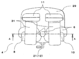
図2は、本実施の形態に係る手指刺激部4を詳細に説明するための図である。手指刺激部4は、被施療者の指および/あるいは掌に振動を付与するための1つ以上の振動体6と、振動体6を保持し、被施療者の指と掌がなす角度に合わせて角度を調節するための後述する第1の回転軸7を中心に独立して回転可能である指支持部材8および後述する第2の回転軸9を中心に独立して回転可能である掌支持部材10と、手背側から指と掌を前記振動体6に押し付けて固定するための押し付け部11と、指支持部材8と掌支持部材9の回転を同時に抑制するための固定手段12を備える。
FIG. 2 is a diagram for describing the
本実施の形態において、振動体6とは例えばモーターに偏心した錘を取り付けた偏心モーターや、圧電素子を用いた振動体である。振動体6は、指支持部材8と掌支持部材10それぞれに備えられている。振動体6の数はそれぞれ1つに限定されるものではなく、2つ以上であってもよい。また、振動体6を指支持部材8と掌支持部材10のいずれか1つに備えてもよい。
In the present embodiment, the vibrating
手指刺激部4は、土台29の下部に支持台35を備えている。支持台35の底面は、曲面形状になっており、机やベッドなどの設置面との設置面積が小さくなるようになっている。そのため、支持台35の底面と設置面との間の抵抗が少なくなるので、手指刺激部4を回転させやすくなり、手首の背屈を容易に行うことができる。また、土台29と支持台35の間には、弾性部材36を備えている。弾性部材36を備えていることで、振動体6の振動を弾性部材36が吸収し、支持台35や接地面に伝わる振動を減少させるので、騒音を低減することができる。このとき、支持台35と接地面との接地面積が小さいことも騒音低減に繋がる。
The
支持台35は押さえ部37を備えている。通常、手首を背屈した際は、背屈状態をもとに戻そうとする力が働き、弾性部材36が変形し、背屈角度が少し戻ってしまうが、支持台35に押さえ部37を備えていることで、弾性部材36の変形を防ぐことができる。
The
押し付け部11は、指と掌それぞれの手背に当接する当接面30と、指と掌を前記振動体6に押し付けた状態で固定するための固定具31を備えている。固定具31は、例えばベルトや面ファスナー、ゴム等である。固定具31は、指支持部材8と掌支持部材10それぞれに備える。固定具31の端は、指支持部材8と掌支持部材10のそれぞれの底面に接続されており、固定具31の中間部分は押し付け部11の手背への当接面30の反対側に接続され、固定具31の指支持部材8と掌支持部材10の底面に接続されていない他端は、面ファスナーなどが取り付けられており、前記振動体6に対して被施療者の手部を固定できるようになっている。
The
図3は本実施の形態に係る手指刺激部4を上側から見た図であり、図4は図3に示したA−A断面を矢印方向から見た図である。図4に示すように、指支持部材8は軸孔39を有する回転部13、掌支持部材10は軸孔40を有する回転部14を有している。回転部13は第1の回転軸7、回転部14は第2の回転軸9を中心に回転可能である。回転部13と回転部14とはそれぞれの軸孔39、40の位置が一致するように、回転部14が上側となるように設置されている。指支持部材8の回転部13は、下側に向けて開口した円筒状に構成されており、円筒形状の内側には中空状の軸棒15が軸棒15の中心が回転部13の軸孔39の中心に一致するように固定されている。回転部14の軸孔40、回転部13の軸孔39、軸棒15には軸棒18が挿入されており、軸棒18は回転部14の軸孔40に挿入固定されている。この構成により、回転部13と回転部14とは、軸棒18を同一の中心軸として回転するように構成されている。すなわち、本実施形態では第1の回転軸7と第2の回転軸9の位置は一致している。上記の構成により、指支持部材8と掌支持部材10は、回転軸の位置が一致していても、それぞれが独立して回転することが可能となっており、被施療者毎の手指の最大伸展位に合わせて、角度調節ができる。
FIG. 3 is a diagram of the
軸棒15の下部には駒16が接続されている。駒16は円盤状の上面の中心に開口を有し、開口に軸棒15が挿入されて固定されている。駒16の円盤状の上面の外周から下側に向けて突出部が設けられており、突出部には円周方向に一定の角度間隔で複数の孔17が備えられている。また、軸棒18の下部には円筒状の駒19が接続されており、駒19の外周上には一定の角度間隔で複数の穴20が備えられている。本実施形態においては、駒16の突出部の内側に駒19が位置する構成になっている。駒16は、軸棒15を通して指支持部材8(回転部13)に接続されているため、指支持部材8の回転に追従して回転することができる。また、掌支持部材10の回転部14は、軸棒18に接続されている。駒19は、軸棒18を通して掌支持部材10に接続されているため、掌支持部材10の回転に追従して回転することができる。
A
図5は本実施の形態に係る手指刺激部4を側面から見た図であり、図6は図5に示したB−B断面を矢印方向から見た図である。図6に示すように、前記1つの固定手段12によって、指支持部材8と掌支持部材10は、角度調節後に回転しないように同時に固定される。1つの固定手段12は、例えばプランジャ21等である。凹型の駒16と凹型内部に位置する駒19の外周上の複数の孔17と複数の穴20は、指支持部材8と掌支持部材10の回転に追従して回転し、一定角度(本実施例では15度毎)で位置が揃う構成になっている。一定角度で位置が揃った孔17と穴20に手指刺激部4の側面側からプランジャ21等のピンを、孔17を貫通して穴20に届くように挿し込むことで駒16、19の回転を同時に固定することができ、駒16、19と軸棒15、18を通して接続されている指支持部材8と掌支持部材10の回転も同時に固定することができる。図示しないが、プランジャ等21のピンの挿し込む方向は、装置の側面側からだけでなく、装置の上下面からでもよい。その場合、駒16の複数の孔17と駒19の複数の穴20の位置は、駒16、19の上面や下面に備え、複数の穴20は貫通孔となる。
前記駒16、19に有する複数の孔17と複数の穴20はスリット構造とし、前記固定手段12は板形状等の挿入部材などでもよい。
FIG. 5 is a diagram of the
The plurality of
なお本実施形態では固定手段12は指支持部材8と掌支持部材10の回転を禁止するが、これに限られるものではなく、振動刺激の施療中に両支持部材が容易に回転しない程度に回転を抑制することができればよい。図7は、さらに別の実施の形態に係る手指刺激部4を詳細に説明するための図である。図8は本実施の形態に係る手指刺激部4を上面から見た図であり、図9は図8に示したD−D断面を矢印方向から見た図である。図10は本実施の形態に係る手指刺激部4を側面から見た図であり、図11は図10に示したE−E断面を矢印方向から見た図である。なお、他の実施形態と重複する部分が多いことから、以下では本実施形態に特徴的な部分のみを説明し、その他の構成についての説明は省略する。図面の説明においては他の実施形態と同一要素には同一符号を付し、重複する説明を省略する。
In this embodiment, the fixing means 12 prohibits the rotation of the
本実施形態においては、指支持部材8の回転部41の軸孔43には、軸棒45が挿入接続されている。軸棒45の下部には駒47が接続されている。駒47は、軸棒45を介して指支持部材8に接続されているため、指支持部材8の回転に追従して回転する。
In the present embodiment, a
また、掌支持部材10の回転部42の軸孔44には、軸棒46が挿入接続されている。軸棒46の下部には駒48が接続されている。駒48は、軸棒46を通して掌支持部材10に接続されているため、掌支持部材10の回転に追従して回転する。本実施形態においては指支持部材8の回転部41の第1の回転軸7と掌支持部材10の回転部42の第2の回転軸9の位置は一致していない。
In addition, a
駒47の円周上には一定の角度間隔で複数の孔49が備えられている。駒47は、略扇形であり、厚みが厚い厚板部と厚板部の端面から突出する厚みが薄い薄板部51を有しており、薄板部51には円周方向に一定の角度間隔で複数の孔49が設けられている。厚板部の薄板部が突出している端面には、薄肉部51の突出部分と隣接して、端面を一部切り欠いた空洞部53が設けられている。
A plurality of
駒48は、略扇形であり、厚みが厚い厚板部と厚板部の端面から突出する厚みが薄い薄板部52を有しており、薄板部52には円周方向に一定の角度間隔で複数の孔50が設けられている。
The
図12に示すように、駒47の薄板部51と駒48の薄板部52は重なるように設置されており、薄板部51が、薄板部52の下部に位置する構成になっている。また、駒48を回転させた際に、薄板部51が駒47に接触するのを防ぐために、駒48を回転させた際に薄板部52が空洞部53を通る構成になっている。そのため、駒47と駒48が接触することなく指支持部材8と掌支持部材10は独立して回転することが可能となっており、被施療者毎の手指の最大伸展位に合わせて、角度調節ができる。また、必要以上に指支持部材8と掌支持部材10が回転しないように、一定角度(本実施例では45度)回転したところで駒47と駒48の板厚が厚い部分が接触し、それ以上回転しないような構成になっている。
As shown in FIG. 12, the
本実施形態に係る手指刺激部4は固定手段12を備え、前記1つの固定手段12によって、指支持部材8と掌支持部材10は、角度調節後に回転しないように同時に固定される。1つの固定手段12は、例えばプランジャ54等である。上述のように駒47の薄板部51と駒48の薄板部52は重なるようになっており、駒47の薄板部51と駒48薄板部52上のそれぞれの複数の孔49、50は、指支持部材8と掌支持部材10の回転に追従して回転し、一定角度(本実施例では15度毎)で孔49と孔50の位置が揃う構成になっている。一定角度で位置が揃った孔49、50に手指刺激部4の底面側からプランジャ54等のピンを、孔49を貫通して孔50に届くように挿し込むことで駒47、48の回転を同時に固定することができ、駒47、48と軸棒45、46を通して接続されている指支持部材8と掌支持部材10の回転も同時に固定することができる。図示しないが、プランジャ等54のピンを挿し込む方向は、装置の底面側からだけでなく、装置の上面側や側面側からでもよい。その場合、駒47、48の複数の孔49、50の位置は、駒47、48の上面や円周上に備える。側面からピンを挿し込む場合は、薄板部51、52のそれぞれの側面に上下で対となる半円の穴を備え、一定角度で対の半円が一致することで円を構成し、構成された円にピンを挿し込むことで固定することができる。
The
図示しないが、前記駒47、48に有する孔49、50はスリット構造、前記固定手段12は板形状等の挿入部材などでもよい。
Although not shown, the
なお本実施形態では固定手段12は指支持部材8と掌支持部材10の回転を禁止するが、これに限られるものではなく、振動刺激の施療中に両支持部材が容易に回転しない程度に回転を抑制することができればよい。
In this embodiment, the fixing means 12 prohibits the rotation of the
図13は、さらに別の実施の形態に係る手指刺激部4を詳細に説明するための図である。図14は本実施の形態に係る手指刺激部4を上面から見た図であり、図15は図14に示したF−F断面を矢印方向から見た図である。なお、他の実施形態と重複する部分が多いことから、以下では本実施形態に特徴的な部分のみを説明し、その他の構成についての説明は省略する。図面の説明においては他の実施形態と同一要素には同一符号を付し、重複する説明を省略する。
FIG. 13 is a diagram for describing the
本実施形態においては、前記固定手段12は、前記指支持部材8の回転部13の第1の回転軸7と前記掌支持部材10の回転部14の第2の回転軸9の位置が一致している状態で、固定手段25によって第1の回転軸7と第2の回転軸9に軸方向から押さえ付ける力を加えることで指支持部材8と掌支持部材10の回転を同時に抑制する。
In the present embodiment, the position of the
指支持部材8は軸孔39を有する回転部13、掌支持部材10は軸孔40を有する回転部14を有している。回転部13は第1の回転軸7、回転部14は第2の回転軸9を中心に回転可能である。回転部13と回転部14とはそれぞれの軸孔39、40の位置が一致するように、回転部14が上側となるように設置されている。指支持部材8の回転部13は、下側に向けて開口した円筒状に構成されており、円筒形状の内側には中空状の軸棒15が軸棒15の中心が回転部13の軸孔39の中心に一致するように固定されている。回転部14の軸孔40、回転部13の軸孔39、軸棒15には軸棒18が挿入されており、軸棒18は回転部14の軸孔40に挿入固定されている。この構成により、回転部13と回転部14とは、軸棒18を同一の中心軸として回転するように構成されている。すなわち、本実施形態では第1の回転軸7と第2の回転軸9の位置は一致している。上記の構成により、指支持部材8と掌支持部材10は、回転軸の位置が一致していても、それぞれが独立して回転することが可能となっており、被施療者毎の手指の最大伸展位に合わせて、角度調節ができる。
The
軸棒15の下部には駒55が接続されている。駒55は円盤状の底面の中心に開口を有し、開口に軸棒15が挿入されて固定されている。また、軸棒18の下部には円筒状の駒56が接続されている。本実施形態においては、駒55の下部に駒54が位置する構成になっている。駒55は、軸棒15を通して指支持部材8(回転部13)に接続されているため、指支持部材8の回転に追従して回転することができる。また、掌支持部材10の回転部14は、軸棒18に接続されている。駒56は、軸棒18を通して掌支持部材10に接続されているため、掌支持部材10の回転に追従して回転することができる。
A
押さえ付ける力を加える固定手段25は、例えばレバー26であり、レバー26の先には駒16、19程度の大きさの円盤形状などの押し付け部27を備えている。レバー26は回転軸28を備えており、レバー26を下げることで、押し付け部27が上がるようになっている。レバー26を下げることによって、押し付け部27が上がり、駒55に接触し、力が加わるため、第1の回転軸7と第2の回転軸9にも軸方向から力を加えることができる。第1の回転軸7と第2の回転軸9に軸方向から力が加わることで、駒55、56が軸方向に押し上げられ、駒55と手指刺激部4の土台29の間や駒55と駒56の間や押し付け部27と駒56の間で生じる摩擦力が大きくなり、摩擦力によって指支持部材8と掌支持部材10の回転を同時に抑制することができる。この場合、押し付けた際の各接触部には摩擦力を向上させるために、ゴム等の材料を使用しても良い。
The fixing means 25 for applying the pressing force is, for example, a
図16は、さらに別の実施の形態に係る手指刺激部4を詳細に説明するための図である。図17は本実施の形態に係る手指刺激部4を上面から見た図であり、図18は図17に示したG−G断面を矢印方向から見た図であり、図19は図17に示したH−H断面を矢印方向から見た図である。なお、他の実施形態と重複する部分が多いことから、以下では本実施形態に特徴的な部分のみを説明し、その他の構成についての説明は省略する。図面の説明においては他の実施形態と同一要素には同一符号を付し、重複する説明を省略する。
FIG. 16 is a diagram for describing the
本実施形態においては、前記固定手段12は、前記指支持部材8の回転部13の第1の回転軸7と前記掌支持部材10の回転部14の第2の回転軸9の位置が一致していない状態でも、固定手段25によって第1の回転軸7と第2の回転軸9に軸方向から押さえ付ける力を加えることで指支持部材8と掌支持部材10の回転を抑制する。指支持部材8の回転部41の軸孔43には、軸棒45が挿入接続されている。軸棒45の下部には扇形の駒57が接続されている。駒57は、軸棒45を介して指支持部材8に接続されているため、指支持部材8の回転に追従して回転する。また、掌支持部材10の回転部42の軸孔44には、軸棒46が挿入接続されている。軸棒46の下部には扇形の駒58が接続されている。駒58は、軸棒46を通して掌支持部材10に接続されているため、掌支持部材10の回転に追従して回転する。本実施形態においては指支持部材8の回転部41の第1の回転軸7と掌支持部材10の回転部42の第2の回転軸9の位置は一致していない。
In the present embodiment, the position of the
また、図20に示すように駒57と駒58の底面の高さは同じになっているが、それぞれの駒が扇形になっているため、一定角度(本実施例では45度)まで、指支持部材8と掌支持部材10は独立して回転することが可能となっており、被施療者毎の手指の最大伸展位に合わせて、角度調節ができる。
Also, as shown in FIG. 20, the heights of the bottom surfaces of the
押さえ付ける力を加える固定手段25は、例えばレバー26等であり、レバー26の先には駒57、58をあわせた程度の大きさの円盤形状などの押さえつけ部27を備えている。
The fixing means 25 for applying the pressing force is, for example, a
[装置の使用例]
図21〜23を用いて、本形態に係る振動刺激装置の使用例を説明する。
[Example of device use]
An example of use of the vibration stimulator according to the present embodiment will be described with reference to FIGS.
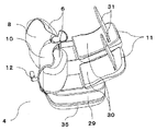
前記振動刺激装置1へ手指を装着する際は、図21に示すように、前記指支持部材8と前記掌支持部材10および指と掌の押し付け部11が開口状態である振動刺激装置に、屈曲した手指38を、指支持部材8と掌支持部材10に保持された前記振動体6に当接するように置く。
When a finger is attached to the
次に、前記押し付け部11の前記当接面30を指と掌のそれぞれの手背側に当接させた状態で、それぞれの前記固定具14のベルト等の前記指支持部材8と前記掌支持部材10に接続されていない方の端を引っ張り、押し付け部11を指と掌に押さえ付け、指と掌が振動体6に押し付けられた状態で面ファスナー等によって固定する。
Next, in a state where the
次に、前記指支持部材8と前記掌支持部材10の角度を、被施療者の最大伸展位まで角度変更し、最大伸展位状態で1つの前記固定手段6であるプランジャ21のピンを駒16の孔17と駒19の穴20に挿すことで指支持部材8と掌支持部材10の角度を固定する。
Next, the angle between the
最後に、手指刺激部4を角度調節機構33の回転軸34を中心に回転させ、手首を被施療者の最大背屈位まで背屈させる。
Finally, the
本装置は、前記指支持部材8と前記掌支持部材10および指と掌の押し付け部11が対称構造になっているため、左右どちらの手にも装着することができる。
Since the
本手法によれば、前記角度調節部を最大角度まで開いた状態で、屈曲状態の手指を装置に装着し、指と掌の前記角度調節部それぞれを調節した後、指と掌の角度を1つの固定部材によって同時に固定できることで、簡単に被施療者毎の手指の他動的関節可動域に合わせて装置を装着することが可能となる。 According to this method, with the angle adjustment unit opened to the maximum angle, a finger in a bent state is attached to the device, and after adjusting each of the angle adjustment units for the finger and the palm, the angle between the finger and the palm is set to 1 Since the fixing can be performed by the two fixing members at the same time, it becomes possible to easily mount the device in accordance with the movable range of the passive joint of the fingers of each user.
1 振動刺激装置
2 上腕刺激部
3 前腕刺激部
4 手指刺激部
5 前腕支持部
6 振動体
7 第1の回転軸
8 指支持部材
9 第2の回転軸
10 掌支持部材
11 押し付け部
12 固定手段
13 回転部(指)
14 回転部(掌)
15 軸棒(指)
16 駒(指)
17 複数の孔(指)
18 軸棒(掌)
19 駒(掌)
20 複数の穴(掌)
21 プランジャ
22 スリット(指)
23 スリット(掌)
24 板形状の挿入部材
25 固定手段
26 レバー
27 押さえつけ部
28 回転軸
29 手指刺激部4の手を乗せる土台
30 当接面
31 固定具
32 接続部
33 角度調節機構
34 回転軸
35 支持台
36 弾性部材
37 押さえ部
38 手指
39 軸孔(指)
40 軸孔(掌)
41 回転部(指)
42 回転部(掌)
43 軸孔(指)
44 軸孔(掌)
45 軸棒(指)
46 軸棒(掌)
47 駒(指)
48 駒(掌)
49 複数の孔(指)
50 複数の孔(掌)
51 薄板部(指)
52 薄板部(掌)
53 空洞部
54 プランジャ
55 駒(指)
56 駒(掌)
57 駒(指)
58 駒(掌)
DESCRIPTION OF
14 Rotating part (palm)
15 Shaft bar (finger)
16 pieces (finger)
17 Multiple holes (fingers)
18 Axle rod (palm)
19 pieces (palm)
20 multiple holes (palms)
21 plunger 22 slit (finger)
23 slit (palm)
Reference Signs List 24 Plate-shaped
40 shaft hole (palm)
41 Rotating part (finger)
42 Rotating part (palm)
43 Shaft hole (finger)
44 Shaft hole (palm)
45 Shaft bar (finger)
46 Axle (palm)
47 pieces (finger)
48 pieces (palm)
49 multiple holes (fingers)
50 multiple holes (palms)
51 Thin plate (finger)
52 Thin plate (palm)
53
56 pieces (palm)
57 pieces (finger)
58 pieces (palm)
Claims (4)
被施療者の掌を支持し、第2の回転軸を中心に独立して回転可能である掌支持部材と、
前記指支持部材及び/または前記掌支持部材に保持された振動体と、
手背側から前記被施療者の指及び/または掌を前記振動体に押し付けて固定するための押し付け部と、
前記指支持部材及び前記掌支持部材の回転を同時に抑制する固定手段と、を備えた振動刺激装置。 A finger support member that supports the user's finger and is independently rotatable about the first rotation axis;
A palm support member that supports the palm of the user and is independently rotatable about the second rotation axis;
A vibrator held by the finger support member and / or the palm support member;
A pressing portion for pressing the user's finger and / or palm against the vibrating body from the back of the hand to fix the same;
A vibration stimulating device comprising: fixing means for simultaneously suppressing rotation of the finger support member and the palm support member.
前記固定手段は、前記指支持部材及び前記掌支持部材の前記挿入部に挿入部材を挿入することで、前記指支持部材と前記掌支持部材の回転を抑制する、請求項1または2に記載の振動刺激装置。 The finger support member and the palm support member each include a plurality of insertion portions,
The said fixing means suppresses rotation of the finger support member and the palm support member by inserting an insert member into the insertion part of the finger support member and the palm support member. Vibration stimulator.
Priority Applications (1)
| Application Number | Priority Date | Filing Date | Title |
|---|---|---|---|
| JP2018184665A JP2020049179A (en) | 2018-09-28 | 2018-09-28 | Vibration stimulator |
Applications Claiming Priority (1)
| Application Number | Priority Date | Filing Date | Title |
|---|---|---|---|
| JP2018184665A JP2020049179A (en) | 2018-09-28 | 2018-09-28 | Vibration stimulator |
Publications (2)
| Publication Number | Publication Date |
|---|---|
| JP2020049179A true JP2020049179A (en) | 2020-04-02 |
| JP2020049179A5 JP2020049179A5 (en) | 2021-09-02 |
Family
ID=69994806
Family Applications (1)
| Application Number | Title | Priority Date | Filing Date |
|---|---|---|---|
| JP2018184665A Pending JP2020049179A (en) | 2018-09-28 | 2018-09-28 | Vibration stimulator |
Country Status (1)
| Country | Link |
|---|---|
| JP (1) | JP2020049179A (en) |
Cited By (1)
| Publication number | Priority date | Publication date | Assignee | Title |
|---|---|---|---|---|
| US11625994B2 (en) | 2014-05-16 | 2023-04-11 | Not Impossible, Llc | Vibrotactile control systems and methods |
Citations (6)
| Publication number | Priority date | Publication date | Assignee | Title |
|---|---|---|---|---|
| JP2000175946A (en) * | 1998-12-17 | 2000-06-27 | Toshio Sugawara | Finger orthodontic tool |
| JP2004313768A (en) * | 2003-04-01 | 2004-11-11 | Daisaku Tokunaga | Habiliment having auxiliary function for extension and flection |
| JP2013017718A (en) * | 2011-07-13 | 2013-01-31 | R-Techs:Kk | Rehabilitation apparatus for fingers |
| US20130116606A1 (en) * | 2010-07-12 | 2013-05-09 | Oregon Health & Science University | Method and device for reducing symptomatic relapse of spasticity |
| US9446288B1 (en) * | 2013-01-28 | 2016-09-20 | Steven E. Pazan | Exercise and therapy device having SPNRED material |
| CN206463444U (en) * | 2016-07-22 | 2017-09-05 | 绍兴文理学院 | A kind of patients with cerebral apoplexy wrist joint exerciser |
-
2018
- 2018-09-28 JP JP2018184665A patent/JP2020049179A/en active Pending
Patent Citations (6)
| Publication number | Priority date | Publication date | Assignee | Title |
|---|---|---|---|---|
| JP2000175946A (en) * | 1998-12-17 | 2000-06-27 | Toshio Sugawara | Finger orthodontic tool |
| JP2004313768A (en) * | 2003-04-01 | 2004-11-11 | Daisaku Tokunaga | Habiliment having auxiliary function for extension and flection |
| US20130116606A1 (en) * | 2010-07-12 | 2013-05-09 | Oregon Health & Science University | Method and device for reducing symptomatic relapse of spasticity |
| JP2013017718A (en) * | 2011-07-13 | 2013-01-31 | R-Techs:Kk | Rehabilitation apparatus for fingers |
| US9446288B1 (en) * | 2013-01-28 | 2016-09-20 | Steven E. Pazan | Exercise and therapy device having SPNRED material |
| CN206463444U (en) * | 2016-07-22 | 2017-09-05 | 绍兴文理学院 | A kind of patients with cerebral apoplexy wrist joint exerciser |
Cited By (1)
| Publication number | Priority date | Publication date | Assignee | Title |
|---|---|---|---|---|
| US11625994B2 (en) | 2014-05-16 | 2023-04-11 | Not Impossible, Llc | Vibrotactile control systems and methods |
Similar Documents
| Publication | Publication Date | Title |
|---|---|---|
| US10406065B2 (en) | Device for delivery of resonant frequencies to treated muscles | |
| Ma et al. | Comparing biofeedback with active exercise and passive treatment for the management of work-related neck and shoulder pain: a randomized controlled trial | |
| US6878122B2 (en) | Method and device for rehabilitation of motor dysfunction | |
| King et al. | Short-term effects of vibration therapy on motor impairments in Parkinson's disease | |
| RU2648860C2 (en) | Vibration system and method for stimulating human body by creating a proprioceptive resonance | |
| US20130116606A1 (en) | Method and device for reducing symptomatic relapse of spasticity | |
| EA034480B1 (en) | Neck training apparatus | |
| EP2370042B1 (en) | Method of passive mechanotherapy and exercise machine for implementation thereof | |
| JP2020049179A (en) | Vibration stimulator | |
| Xia et al. | A comparison of the effects of imposed extension and flexion movements on Parkinsonian rigidity | |
| US10195097B1 (en) | Neuromuscular plasticity apparatus and method using same | |
| US10799416B2 (en) | Self-treating upper neck system for therapeutic mobilization | |
| WO2018180399A1 (en) | Vibration stimulation device | |
| Lee et al. | Evaluating the differential electrophysiological effects of the focal vibrator on the tendon and muscle belly in healthy people | |
| Ribot-Ciscar et al. | Sensory training with vibration-induced kinesthetic illusions improves proprioceptive integration in patients with Parkinson's disease | |
| Gelber et al. | Clinical evaluation and management of spasticity | |
| US11576807B2 (en) | Method of treating pain | |
| WO2018180400A1 (en) | Vibratory stimulation device | |
| Komura et al. | Degree of muscle-and-tendon tonus effects on kinesthetic illusion in wrist joints toward advanced rehabilitation robotics | |
| Levine et al. | Proprioceptive facilitation of voluntary motion in man | |
| RU2408354C2 (en) | Method of treating infantile cerebral paralysis | |
| JP2020049179A5 (en) | ||
| RU2179009C2 (en) | Method and device for restoring nervous, muscular and motor coordination in patients suffering from central nervous system disorders | |
| CN219000786U (en) | Shoulder joint abduction support | |
| JP7339659B2 (en) | Relief device for the shoulder and neck region |
Legal Events
| Date | Code | Title | Description |
|---|---|---|---|
| A521 | Request for written amendment filed |
Free format text: JAPANESE INTERMEDIATE CODE: A523 Effective date: 20210706 |
|
| A621 | Written request for application examination |
Free format text: JAPANESE INTERMEDIATE CODE: A621 Effective date: 20210706 |
|
| A977 | Report on retrieval |
Free format text: JAPANESE INTERMEDIATE CODE: A971007 Effective date: 20220323 |
|
| A131 | Notification of reasons for refusal |
Free format text: JAPANESE INTERMEDIATE CODE: A131 Effective date: 20220329 |
|
| A521 | Request for written amendment filed |
Free format text: JAPANESE INTERMEDIATE CODE: A523 Effective date: 20220524 |
|
| A131 | Notification of reasons for refusal |
Free format text: JAPANESE INTERMEDIATE CODE: A131 Effective date: 20220913 |
|
| A02 | Decision of refusal |
Free format text: JAPANESE INTERMEDIATE CODE: A02 Effective date: 20230207 |