JP2020032994A - Travel support method and travel support device - Google Patents
Travel support method and travel support device Download PDFInfo
- Publication number
- JP2020032994A JP2020032994A JP2019061696A JP2019061696A JP2020032994A JP 2020032994 A JP2020032994 A JP 2020032994A JP 2019061696 A JP2019061696 A JP 2019061696A JP 2019061696 A JP2019061696 A JP 2019061696A JP 2020032994 A JP2020032994 A JP 2020032994A
- Authority
- JP
- Japan
- Prior art keywords
- point
- route
- vehicle
- line
- start point
- Prior art date
- Legal status (The legal status is an assumption and is not a legal conclusion. Google has not performed a legal analysis and makes no representation as to the accuracy of the status listed.)
- Granted
Links
- 238000000034 method Methods 0.000 title claims abstract description 95
- 238000004364 calculation method Methods 0.000 claims description 6
- 238000013459 approach Methods 0.000 claims description 5
- 238000010586 diagram Methods 0.000 description 17
- 238000012545 processing Methods 0.000 description 17
- 230000006870 function Effects 0.000 description 6
- 238000011156 evaluation Methods 0.000 description 4
- 238000003860 storage Methods 0.000 description 4
- 238000004590 computer program Methods 0.000 description 3
- 230000014509 gene expression Effects 0.000 description 3
- 238000004519 manufacturing process Methods 0.000 description 3
- 230000006399 behavior Effects 0.000 description 2
- 230000000694 effects Effects 0.000 description 2
- 230000009191 jumping Effects 0.000 description 2
- QNRATNLHPGXHMA-XZHTYLCXSA-N (r)-(6-ethoxyquinolin-4-yl)-[(2s,4s,5r)-5-ethyl-1-azabicyclo[2.2.2]octan-2-yl]methanol;hydrochloride Chemical compound Cl.C([C@H]([C@H](C1)CC)C2)CN1[C@@H]2[C@H](O)C1=CC=NC2=CC=C(OCC)C=C21 QNRATNLHPGXHMA-XZHTYLCXSA-N 0.000 description 1
- 241001465754 Metazoa Species 0.000 description 1
- 238000004891 communication Methods 0.000 description 1
- 238000012986 modification Methods 0.000 description 1
- 230000004048 modification Effects 0.000 description 1
- 238000003825 pressing Methods 0.000 description 1
- 230000008929 regeneration Effects 0.000 description 1
- 238000011069 regeneration method Methods 0.000 description 1
- 239000000725 suspension Substances 0.000 description 1
- 230000000007 visual effect Effects 0.000 description 1
Images


Landscapes
- Control Of Driving Devices And Active Controlling Of Vehicle (AREA)
- Traffic Control Systems (AREA)
Abstract
Description
この明細書における開示は、車両の走行を支援する走行支援方法および走行支援装置に関する。 The disclosure in this specification relates to a driving support method and a driving support device that support driving of a vehicle.
特許文献1には、移動ロボットを無人運転するために用いる軌道生成方法が開示されている。この軌道生成方法では、道路領域内の主要通過点を通るスプライン曲線を生成し、スプライン曲線が道路領域から出ていないか否かを評価する。この軌道生成方法において、スプライン曲線が道路領域から出ていない場合、そのスプライン曲線が軌道として採用される。
特許文献1の技術では、生成されるスプライン曲線は道路領域から出ていなければ軌道として採用される。このため、道路領域内で左右にぶれたスプライン曲線が生成された場合でも軌道として採用される場合がある。したがって、この技術を車両のカーブ走行時の走行支援に適用すると、走行に伴う車両の左右へのぶれが大きくなる虞がある。
In the technique of
開示される目的は、カーブ走行時の自車両のぶれを抑制可能な走行支援方法および走行支援装置を提供することである。 It is an object of the present disclosure to provide a driving support method and a driving support device capable of suppressing the shake of the host vehicle when traveling on a curve.
この明細書に開示された複数の態様は、それぞれの目的を達成するために、互いに異なる技術的手段を採用する。 The embodiments disclosed in this specification employ different technical means from each other in order to achieve the respective objects.
開示された走行支援方法のひとつは、コンピュータ(100)によって実施され、自車両の走行を支援する走行支援方法であって、少なくとも1つのプロセッサ(101)上において、自車両をカーブ走行させる経路の始点および終点を設定し(S21)、始点および終点を2頂点とする三角形を想定し(S22)、三角形の2辺上にそれぞれ制御点を設定することにより、制御点、始点および終点を4頂点とする四角形を想定し(S24)、四角形内に収まる経路線を算定し(S25)、経路線に沿った自車両のカーブ走行を支援する(S100)、というステップを含む。 One of the disclosed driving support methods is implemented by a computer (100), and is a driving support method for supporting the driving of the own vehicle. A starting point and an ending point are set (S21), a triangle having the starting point and the ending point as two vertices is assumed (S22), and control points are set on two sides of the triangle, so that the control point, the starting point and the ending point are four vertices. (S24), a route line that fits within the rectangle is calculated (S25), and the vehicle travels along a curve along the route line (S100).
開示された走行支援装置のひとつは、自車両をカーブ走行させる経路の始点および終点を設定し、始点および終点を2頂点とする三角形を想定する点設定部(S21、S22)と、三角形の2辺上にそれぞれ制御点を設定することにより、制御点、始点および終点を4頂点とする四角形を想定し、四角形内に収まる経路線を算定する経路線算定部(S24、S25)と、経路線に沿った自車両のカーブ走行を支援するカーブ走行支援部(S100)と、を備える。 One of the disclosed driving support devices sets a start point and an end point of a route that causes a vehicle to make a curve run, and sets a point setting unit (S21, S22) that assumes a triangle having the start point and the end point as two vertices; By setting a control point on each side, a quadrilateral having four vertices as the control point, the start point, and the end point is assumed, and a path line calculation unit (S24, S25) for calculating a path line falling within the rectangle; And a curve traveling support unit (S100) for supporting the vehicle traveling along a curve along the road.
これらの開示によれば、四角形内から逸脱する経路線の生成を抑制できる。以上により、カーブ走行時の自車両のぶれを抑制可能な走行支援方法および走行支援装置を提供することができる。 According to these disclosures, it is possible to suppress generation of a path line that deviates from within a rectangle. As described above, it is possible to provide a driving support method and a driving support device capable of suppressing the shake of the own vehicle when traveling on a curve.
図面を参照しながら、複数の実施形態を説明する。図1〜図24には、走行支援方法および走行支援装置100が開示されている。
A plurality of embodiments will be described with reference to the drawings. 1 to 24 disclose a driving support method and a
(第1実施形態)
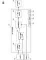
走行支援装置100は、例えば自車両の車載ECUによって提供される。車載ECUは、車両に搭載されるコンピュータであって、少なくとも1つのプロセッサ101と、RAM102と、メモリ装置103と、入出力インターフェイス104と、それらを接続するバスとを備えるマイクロコンピュータを主体として構成されている。より具体的な例として走行支援装置100は、自車両の自動運転走行を制御する自動運転ECUによって提供される。走行支援装置100は、図1に示すように、地図DB10、外界センサ20および車両制御ECU30に、車載ネットワークを介して通信可能に接続されている。
(1st Embodiment)
The
地図DB10は、不揮発性メモリを主体に構成されており、自動運転のために整備された高精度な地図データ(以下、「高精度地図データ」)を記憶している。地図DB10は、高精度地図データとして、道路形状および構造物の特徴点の点群からなる三次元地図情報や、走行区画線、停止線、横断歩道および交差点の中央標示等の形状情報および位置情報、道路の属性情報等を含んでいる。ここで道路の属性情報とは、道路の車線が直進車線のみか、右折専用車線もあるかなどの情報である。地図DB10は、例えばGNSS受信機によって自車両の現在位置を取得するロケータに搭載されている。 The map DB 10 mainly includes a non-volatile memory, and stores high-precision map data prepared for automatic driving (hereinafter, “high-precision map data”). The map DB 10 includes, as high-accuracy map data, three-dimensional map information composed of point groups of road shapes and feature points of structures, and shape information and position information such as lane markings, stop lines, pedestrian crossings, and center signs of intersections. , Road attribute information, and the like. Here, the attribute information of the road is information such as whether the lane of the road is only a straight lane or whether there is also a right turn lane. The map DB 10 is mounted on a locator that acquires the current position of the own vehicle using, for example, a GNSS receiver.
なお、地図DB10は、ナビゲーション装置による経路案内のための地図データを大量に記憶したデータベースであってもよい。 The map DB 10 may be a database that stores a large amount of map data for route guidance by the navigation device.
外界センサ20は、自車両の周辺環境を監視する自律センサである。外界センサ20は、路上の落下物、ガードレール、縁石、走行区画線等の路面表示、および樹木等の静止物体を検出する。外界センサ20は、歩行者、人間以外の動物、他車両等の移動物体を検出する。外界センサ20は、例えば前方カメラ、LIDAR、ミリ波レーダ等を含む。
The
車両制御ECU30は、自車両の挙動を制御するECUである。車両制御ECU30は、車載アクチュエータ群と直接的または間接的に電気接続されている。車載アクチュエータ群には、例えば、駆動用および回生用のモータジェネレータ駆動用モータ、ブレーキアクチュエータ、並びにステアリングアクチュエータ等を含む。車両制御ECU30は、走行支援装置100から出力された経路の情報に基づいて車載アクチュエータ群を制御し、生成された経路に沿った自車両の自動運転走行を実施する。
The
走行支援装置100は、地図DB10および外界センサ20等から出力された情報に基づいて自車両の走行する経路を生成し、経路に沿った自車両の自律的な運転操作を制御する。一態様として走行支援装置100は、交差点での右折経路を生成する。走行支援装置100は、短縮経路生成部110、大回り経路生成部120、経路選択部140、およびカーブ走行支援部150を機能ブロックとして有する。自動運転ECUの処理部であるプロセッサ101がRAM102へのアクセスによりその一時記憶機能を利用しつつ、メモリ装置103に記憶された走行支援プログラムを実行することにより、走行支援方法が実現される。より具体的には、走行支援装置100は、短縮経路(小回り経路)の生成と、短縮経路への右折待機位置の設定と、大回り経路の生成および右折待機位置の設定と、を実現する。
The
短縮経路生成部110は、短縮経路の生成のために、まず経路線の始点および終点に関する情報を取得する。短縮経路生成部110は、自車両の進入車線における交差点入口を始点、退出車線における交差点出口を終点とする。短縮経路生成部110は、交差点入口(始点)に関する位置情報、および角度情報を取得する。角度情報は、始点における進入車線の交差点への接続角度に関する情報である。加えて短縮経路生成部110は、交差点出口(終点)に関する位置情報、および角度情報を取得する。なお、これらの情報に加えて始点および終点それぞれの左右の白線までの距離情報を取得してもよい。また、短縮経路生成部110は、後述の右折待機位置の計算用に対向車線の始点、終点の位置情報、および角度情報(終点における退出車線の交差点への接続角度に関する情報)、左右の白線までの距離情報、属性情報を取得する。短縮経路生成部110は、これらの情報を、地図DB10から真値として取得する。
The short
または、短縮経路生成部110は、始点および終点に関して少なくとも一部の情報を前方カメラ等の外界センサ20から取得してもよい。例えば短縮経路生成部110は、始点に関する情報を画像認識により取得した停止線の位置、形状等の情報に基づき取得してもよい。または、短縮経路生成部110は、外界センサ20によって先行車がハンドルを切ったタイミングを検出することで始点の位置情報を取得してもよい。また、短縮経路生成部110は、終点に関する情報を退出車線の対向車線における停止線の情報に基づき取得してもよい。また、短縮経路生成部110は、始点および終点に関する情報を、地図DB10からの情報と前方カメラ等の外界センサ20からの情報とを合わせた混合情報として取得してもよい。なお短縮経路生成部110は、始点、終点の車線幅方向における位置を例えば車線の中央とする。
Alternatively, the shortened
また短縮経路生成部110は、交差点中央標示の中心位置情報および大きさ情報や、縁石などの走行不可エリアの中心位置情報および大きさ情報を取得する。走行不可エリアに関しては、多角形や、中心点および内接円または外接円により表現された領域情報として取得することができる。短縮経路生成部110は、これらの情報も、地図DB10、外界センサ20等から取得する。
Further, the shortened
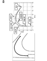
短縮経路生成部110は、点設定部としての機能により、自車両を右折走行させる経路の始点および終点を設定し、始点および終点を2頂点とする三角形を想定する。詳記すると、短縮経路生成部110は、地図DB10から取得した始点、終点の位置情報および角度情報を基に、交差点における進入車線と退出車線の交差領域内に交点Xを設定する。より具体的には、短縮経路生成部110は、図2Aに示すように、始点psから交差点への進入方向、すなわち進入車線の進行方向前方に延びる半直線と、終点pfから交差点からの退出方向の反対方向、すなわち退出車線の進行方向後方に延びる半直線とが交わる点を交点Xとして取得する。3点ps,pf,Xの位置情報の取得により、短縮経路生成部110は、始点ps、終点pfおよび交点Xを頂点とした三角形を想定する。
The shortened
次に短縮経路生成部110は、経路線算定部としての機能により、三角形の2辺上にそれぞれ制御点を追加で設定し、追加した制御点(以下、追加点と表記)、始点および終点を4頂点とする四角形を想定して、四角形内に収まる経路線を算定する。詳記すると、短縮経路生成部110は、三角形の頂点の位置情報に基づき、以下の数式(1)、(2)を満たす2点を追加点p1,p2とする。
![]()
![]()
![]()
![]()
次に短縮経路生成部110は、図2Cに示すように、[ps,p1,p2,pf]の4点を制御点として補間曲線を計算する。これにより、短縮経路生成部110は、想定した四角形内に収まる経路線を算定する。このとき短縮経路生成部110は、自車両やハンドル挙動が暴れないように、曲率連続性を持つ3次以上のパラメータ曲線を補間曲線として補間を行う。パラメータ曲線には、ベジエ曲線、B‐スプライン曲線等が使用される。短縮経路生成部110は、例えば3次のB‐スプライン曲線によって補間を行う場合、始点および終点をそれぞれ3点重複した制御点として扱う。これにより、短縮経路生成部110は、補間曲線として始点および終点を確実に通過するB‐スプライン曲線を算定する。
Then shortened
次に短縮経路生成部110は、曲線評価部として曲率、曲率変化率を基にB‐スプライン曲線を評価する。評価において、短縮経路生成部110はB‐スプライン曲線の最大曲率の大きさおよび曲率のプラスマイナス変化回数がそれぞれの閾値より小さくなるような曲線であるか否かを条件として設定する。短縮経路生成部110は、条件を満たすB‐スプライン曲線を経路線として採用する。短縮経路生成部110は、採用した経路線を短縮経路として経路選択部140に出力する。また、短縮経路生成部110は、短縮経路の始点および終点に関する情報を、大回り経路生成部120へと出力する。
Next, the shortened
一方で条件が満たされなければ、短縮経路生成部110は、図2Dに示すように、α,βの値を変更して追加点p1,p2の位置を変更し、再度B‐スプライン曲線を算定する。以上の繰り返しにより、短縮経路生成部110は、想定された三角形の辺上で追加点を自動的に探索する。
On the other hand, if the condition is not satisfied, the shortened
短縮経路生成部110は、条件を満たした経路線を目標経路(短縮経路)として出力する。以上のようにして、短縮経路生成部110は始点および終点の位置情報と、角度情報とに基づき右折経路を解析的に導出する。
The shortened
また短縮経路生成部110は、図6、図7に示すように、交差点に中央標示がある場合、中央標示に接近しつつも中央標示を走行不可エリアとして避けて走行可能な経路を生成する。ここで中央標示とは、交差点の中央付近に設けられた略菱形形状の標示物であり、車両の走行を誘導する必要のある場所を示す標示物の一例である。具体的に短縮経路生成部110は、まず中央標示からの距離の値を中央標示の大きさ、自車両の幅、予め設定された所定のマージン等に基づき定める。次に短縮経路生成部110は、2点の追加点による線分と中央標示との距離が定めた値になるように追加点位置の設定条件を定める。こうして定めた追加点に基づき、短縮経路生成部110は、上述と同様に経路を生成する(図5および図6参照)。また走行支援装置100は、中央標示に関する情報を、生成した補間曲線の評価時に使用してもよい。
In addition, as shown in FIGS. 6 and 7, when there is a center sign at an intersection, as shown in FIGS. 6 and 7, the shortened
さらに短縮経路生成部110は、走行不可エリアに関する情報を追加点の設定時、補間曲線の評価時等に使用してもよい。
Further, the shortened
また短縮経路生成部110は、交差点領域内において確実に通過する地点情報を取得し、始点および終点と同様に補間曲線が通過する点として、補間曲線の算定時に使用してもよい。
In addition, the shortened
短縮経路生成部110は、生成した短縮経路上に右折待機位置情報を設定する。短縮経路生成部110は、経路線における対向車線を跨ぐ部分よりも始点側に、右折待機位置を設定する。詳記すると、まず短縮経路生成部110は、図8に示すように対向車線の始点および終点に対応する右白線位置を繋いだ線分を計算する。
The short
次に短縮経路生成部110は、生成された短縮経路と上記の線分との交点X〜を取得する。ここで始点から右折待機位置までの経路長をsとおき、交点X〜までの経路長をs〜とする。短縮経路生成部110は、メモリ装置103等に予め記憶された自車両のサイズに基づき、0<s<s〜を満たし、経路上に自車両がいても線分と交差しない(車両が線分から前方側にはみ出さない)点で、且つ最大の経路長となる点を右折待機位置として設定する。
Next, the shortened
これにより短縮経路生成部110は、対向車の走行領域に進入することのない位置且つ車両前景をセンサおよびドライバが認識しやすい位置を右折待機位置として設定する。
Accordingly, the shortened
また短縮経路生成部110は、対向車線の始点および終点に対応する右白線位置を、線分ではなく補間曲線によって繋いでもよい。例えば、対向車線の始点および終点を、後述のLC経路と同様に、設定した通過点を介して補間曲線で繋ぎ、この補間曲線を右白線位置に合わせることで、右白線位置を繋ぐ補間曲線を生成できる。線分の代わりに補間曲線を用いることで、短縮経路生成部110は、より実際の対向車の走行領域に合わせた右折待機位置の設定が可能となる。
Further, the shortened
大回り経路生成部120は、図9〜図11に示すように、短縮経路よりも外側に膨らんで右折走行する経路として大回り経路を生成する。大回り経路生成部120は、まず短縮経路、短縮経路の始点psにおける右白線情報、対向車線の白線情報、自車両のサイズに基づいて、始点から直進走行する距離lを算出する。次に大回り経路生成部120は、始点から距離lだけ直進した地点p〜 sを以下の数式(3)によって算出する。
![]()
![]()
大回り経路は短縮経路の始点から距離lだけ直進した位置を右折待機位置として設定されているので、大回り経路を走行する自車両は、直進方向を向いた状態で右折待機することになる。このため、右折待機中における、自車両の対向車走行領域への飛び出しが抑制され得る。 Since the position of the large turn route that is straight ahead from the start point of the shortened route by the distance l is set as the right turn standby position, the own vehicle traveling on the large turn route waits for the right turn in the straight running direction. Therefore, it is possible to prevent the host vehicle from jumping into the oncoming vehicle traveling area while waiting for a right turn.
大回り経路生成部120は、大回り経路を制御点の追加によって算定してもよい。例えば始点psと追加点p1との間に新たな制御点を設定し、この制御点を通過するような補間曲線を算定することで、大回り経路を生成することができる。
The
大回り経路生成部120は、対向車線がないときには大回り経路を生成しない。また大回り経路生成部120は、対向車線に右折専用車線があるときにも大回り経路を生成しない。これにより大回り経路生成部120は、対向右折車によって対向直進車がセンサによって認識できなくなること、ドライバから視認できなくなること等を抑制できる。
The large turning
経路選択部140は、右折待機位置および角度情報がそれぞれ格納された短縮経路(小回り経路)および大回り経路のうち、実際に走行する右折経路を選択する。
The
経路選択部140は、交差点進入前に対向車の有無を検出してからのステートマシンによる判断と、ドライバの判断とのいずれかに従って走行経路を選択する。例えば経路選択部140は、ドライバが短縮経路を選択すると、短縮経路を右折待機なしで走行する。経路選択部140は、ドライバによる経路選択がなされなかった場合または経路選択機能がオフとなっていた場合で、且つ対向車がある場合には、大回り経路を選択し、右折待機位置にてドライバの許可が得られるまで待機する。一方対向車がない場合には、経路選択部140は短縮経路を選択し、ドライバの許可が得られるまで右折待機位置で待機する。経路選択部140は、ドライバによる進行許可が出るまで待機することで、センシングミスにより対向車を自車両が認識できなかった場合でもドライバの目視による判断に基づいた走行を可能とする。
The
カーブ走行支援部150は、選択された右折経路の情報を車両制御ECU30に出力し、自車両の自律走行を支援する。カーブ走行支援部150は、右折経路に進入後に対向車が検出されると、選択された右折経路の右折待機位置で自車両を停車させるための信号を車両制御ECU30に出力する。
The curve traveling
次に、ここまで説明した交差点右折シーンのカーブ走行支援を実現するため、走行支援装置100にて実施される一連の処理について、図12〜図16に示すフローチャートを参照して説明する。
Next, a series of processes performed by the driving
図12は、交差点右折シーンにおいて経路を生成し、生成した経路に沿った走行を実施する一連の走行支援処理の概要を示すフローチャートである。走行支援装置100は、図12に示す処理を、自車両の自動走行中に繰り返し実行する。
FIG. 12 is a flowchart showing an outline of a series of traveling support processing for generating a route in an intersection right-turn scene and performing traveling along the generated route. The driving
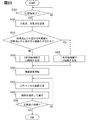
走行支援装置100は、まずステップS10にて、自車両の右折が必要な右折交差点に接近したか否かを判定する。ステップS10の判定処理は、自車両の現在位置と、目的地までの走行予定経路とに基づき実行される。ステップS10は、右折交差点に接近するまで繰り返し実施される。右折交差点に接近したと判定した場合は、ステップS20へと進む。ステップS20では、短縮経路を生成する。
First, in step S10, the driving
短縮経路の生成処理について図13を参照しつつ詳記すると、まずステップS21にて、始点および終点の位置情報、角度情報を取得し、ステップS22へと進む。ステップS22では、角度情報に基づいて交点Xを取得し、ステップS23へと進む。ステップS23では、進入不可エリアの情報から追加点p1,p2の位置の条件を設定する。
The generation process of the shortened route will be described in detail with reference to FIG. 13. First, in step S21, the position information and the angle information of the start point and the end point are obtained, and the process proceeds to step S22. In step S22, the intersection X is obtained based on the angle information, and the process proceeds to step S23. In step S23, it sets the conditions for the position of the
追加点p1,p2の位置の条件の設定について図14を参照しつつ詳記すると、まずステップS231にて、進入不可エリアに関する情報として中央標示情報を取得し、ステップS232へと進む。ステップS232では、中央標示情報に基づいて、中央標示からとるべき距離(例えば中央標示の中心点からの距離)を定め、ステップS233へと進む。ステップS233では、追加点同士を結ぶ線分と中央標示との距離がステップS232にて定めた距離となることを、追加点の位置の条件として設定し、図13のステップS24へと進む。 The setting of the conditions of the positions of the additional points p 1 and p 2 will be described in detail with reference to FIG. 14. First, in step S231, the center sign information is acquired as the information regarding the inaccessible area, and the process proceeds to step S232. In step S232, a distance to be taken from the center sign (for example, a distance from the center point of the center sign) is determined based on the center sign information, and the process proceeds to step S233. In step S233, the condition of the position of the additional point is set such that the distance between the line segment connecting the additional points and the center mark is the distance determined in step S232, and the process proceeds to step S24 in FIG.
ステップS24では、数式(1)、(2)と、ステップS23にて設定された条件とに基づき、追加点p1,p2を設定し、ステップS25へと進む。ステップS25では、始点ps、終点pf、および追加点p1,p2を制御点とし、B‐スプライン曲線を算定してステップS26へと進む。ステップS26では、算定した曲線の曲率と、曲率変化率とを算出してステップS27へと進む。
In step S24, equation (1), and (2), based on the conditions set in step S23, sets the
ステップS27では、算出した曲率および曲率変化率に基づき、曲線の最大曲率と、曲率の符号変化回数とがそれぞれ予め設定された閾値以下であるか否かを判定する。少なくとも一方が閾値を上回ると判定された場合、ステップS28へと進み、数式(1)、(2)におけるα,βの値を変更してステップS24へと戻る。一方で、ステップS27にて最大曲率および曲率の符号変化回数の両方がそれぞれの閾値以下であると判定されると、ステップS29へと進む。ステップS29では、算定した曲線を短縮経路として出力し、図12のステップS30に示す右折待機位置の設定処理へと進む。 In step S27, based on the calculated curvature and the curvature change rate, it is determined whether or not the maximum curvature of the curve and the number of sign changes of the curvature are each equal to or less than a preset threshold. If it is determined that at least one of them exceeds the threshold value, the process proceeds to step S28, changes the values of α and β in Expressions (1) and (2), and returns to step S24. On the other hand, when it is determined in step S27 that both the maximum curvature and the number of sign changes of the curvature are equal to or smaller than the respective thresholds, the process proceeds to step S29. In step S29, the calculated curve is output as a shortened route, and the process proceeds to a right turn standby position setting process shown in step S30 in FIG.
短縮経路上の右折待機位置の設定処理について図15を参照しつつ詳記すると、まずステップS31にて、対向車線の始点情報および終点情報を取得し、ステップS32へと進む。ステップS32では、対向車線の始点および終点に対応する右白線位置を繋いだ線分と短縮経路との交点Xcの位置を取得して、ステップS33へと進む。ステップS33では、交点Xcの位置および自車両のサイズに基づいて短縮経路上に右折待機位置を設定し、図12のステップS40へと進む。 The process of setting the right turn standby position on the shortened route will be described in detail with reference to FIG. 15. First, in step S31, start point information and end point information of the oncoming lane are acquired, and the process proceeds to step S32. In step S32, the position of the intersection Xc between the line segment connecting the right white line positions corresponding to the start point and the end point of the oncoming lane and the shortened route is acquired, and the process proceeds to step S33. In step S33, a right turn standby position is set on the shortened route based on the position of the intersection Xc and the size of the host vehicle, and the process proceeds to step S40 in FIG.
ステップS40では、地図DB10からの情報に基づき、進入車線に対する対向車線の有無を判定する。対向車線が有ると判定すると、ステップS50へと進む。ステップS50では、対向車線に右折専用車線が有るか否かを判定する。右折専用車線が無いと判定すると、ステップS60へと進む。ステップS60では、大回り経路の生成および大回り経路への右折待機位置の設定を行う。
In step S40, based on information from the
大回り経路に関する処理について図16を参照しつつ詳記すると、まず、ステップS61では、短縮経路の始点psから直線で走行する距離lを算出し、ステップS62へと進む。ステップS62では、始点psから距離lだけ直進した地点を、右折待機位置として設定し、ステップS63へと進む。ステップS63では、設定された右折待機位置と終点pfとをつなぐB‐スプライン曲線を、短縮経路の生成(ステップS21〜S29)と同様の方法で生成し、図12のステップS70へと進む。 When Shoki with reference to FIG. 16 for processing about the roundabout route, first, in step S61, and calculates the distance l traveling in a straight line from the starting point p s of shortcut path, the process proceeds to step S62. In step S62, a point which is straight from a starting point p s distance l, and set as the right turn waiting position, the process proceeds to step S63. In step S63, connecting the set right turn waiting position and the end point p f B- spline curve, generated in a similar manner to generate a shortcut path (step S21 to S29), the process proceeds to step S70 in FIG. 12.
ステップS70では、短縮経路および大回り経路のうちで実際の走行経路を選択するために、外界センサ20からの情報に基づき対向車の有無を判定する。対向車が有ると判定されると、ステップS80へと進み、大回り経路を走行経路として選択したのち、ステップS100へと進む。
In step S70, the presence or absence of an oncoming vehicle is determined based on information from the
一方で、ステップS40にて対向車線が無いと判定した場合、またはステップS50にて右折専用車線が有ると判定された場合には、ステップS90へと進む。これらの場合、ステップS90にて、大回り経路を生成することなく短縮経路を走行経路として選択したのち、ステップS100へと進む。 On the other hand, if it is determined in step S40 that there is no oncoming lane, or if it is determined in step S50 that there is a right turn-only lane, the process proceeds to step S90. In these cases, in step S90, after selecting the shortened route as the traveling route without generating the roundabout route, the process proceeds to step S100.
加えて、ステップS70にて対向車が無いと判定した場合にも、ステップS90へと進む。これにより、生成した短縮経路と大回り経路のうち、短縮経路を走行経路として選択し、ステップS100へと進む。 In addition, when it is determined in step S70 that there is no oncoming vehicle, the process proceeds to step S90. Thereby, the shortened route is selected as the traveling route from the generated shortened route and the large turning route, and the process proceeds to step S100.
ステップS100では、選択した経路への自車両の自律走行による進入を開始し、ステップS110へと進む。ステップS110では、経路への進入開始後に、対向車の有無を判定する。ステップS110の判定処理は、経路の右折待機位置に到達するまでの間に実行される。対向車が無いと判定すると、ステップS120へと進む。ステップS120では、右折待機位置で停止することなく、経路に沿った自車両の進行を継続させる。終点に到達して経路の走行が完了すると、一連の処理を終了する。 In step S100, the vehicle starts to enter the selected route by autonomous traveling, and proceeds to step S110. In step S110, it is determined whether there is an oncoming vehicle after entry into the route is started. The determination process in step S110 is performed until the vehicle reaches the right turn standby position on the route. If it is determined that there is no oncoming vehicle, the process proceeds to step S120. In step S120, the traveling of the host vehicle along the route is continued without stopping at the right turn standby position. When the end point is reached and the traveling of the route is completed, a series of processing ends.
一方で、ステップS110にて対向車が有ると判定した場合には、ステップS130へと進む。ステップS130では、対向車の通過を待機するため、選択した経路に設定された右折待機位置にて自車両を停車させ、ステップS140へと進む。 On the other hand, if it is determined in step S110 that there is an oncoming vehicle, the process proceeds to step S130. In step S130, in order to wait for the oncoming vehicle to pass, the host vehicle is stopped at the right turn standby position set on the selected route, and the process proceeds to step S140.
ステップS140では、右折待機位置から発進可能か否かを判定する。例えばステップS140では、外界センサ20の情報に基づき、対向車が検出されなくなった場合に、発進可能であると判定する。または、ステップS140では、ドライバが発進許可スイッチを押すなどして発進許可操作を行った場合に、発進可能であると判定してもよい。ステップS140の判定処理は、発進可能と判定されるまで繰り返し実行される。発進可能であると判定されると、ステップS150へと進む。ステップS150では、自車両を発進させて経路の走行を完了し、一連の処理を終了する。
In step S140, it is determined whether it is possible to start from the right turn standby position. For example, in step S140, when the oncoming vehicle is no longer detected based on the information from the
第1実施形態の走行支援装置100の構成がもたらす作用効果について説明する。
The operation and effect provided by the configuration of the driving
走行支援装置100は、自車両の交差点での右折走行の経路の始点および終点を設定し、始点および終点を2頂点とする三角形の2辺上に追加点を設定する。走行支援装置100は、始点、終点、2点の追加点を4頂点とする四角形に収まる経路線を算定し、経路線に沿った自車両のカーブ走行を支援する。これによれば、走行支援装置100は、四角形内から逸脱する経路線の生成を抑制できる。したがって走行支援装置100は、交差点の右折走行時に自車両のぶれを抑制できる。
The driving
また交差点では、直進路と異なり自車両の両側に車線がない場合が殆どであるため、車線に基づいて右折経路を生成することが困難である。走行支援装置は、これまで説明した方法で経路を生成することにより、交差点領域内における自車両が走行すべき地点情報を多数取得する必要がなくなるため、情報量を比較的抑制しつつ右折経路を生成できる。 In addition, at an intersection, unlike a straight-ahead route, there are almost no lanes on both sides of the own vehicle. Therefore, it is difficult to generate a right-turn route based on the lane. By generating the route in the manner described above, the driving support device does not need to acquire a large number of pieces of point information on which the vehicle should travel in the intersection area. Can be generated.
走行支援装置100は、始点から進入車線に沿う方向に延びる半直線と、終点から退出車線に沿う方向に延びる半直線との交点を三角形の第3の頂点とするので、交差点内において経路線が外側に膨らむようなカーブ形状となることを抑制できる。したがって走行支援装置100は、交差点内における自車両のぶれをより抑制したカーブ走行を支援できる。
The driving
走行支援装置100は、経路線における対向車線を跨ぐ部分よりも始点側に、自車両の右折待機位置を設定する。これによれば、走行支援装置100は、対向車の往来の妨げになることをより確実に回避可能な右折待機位置を設定することができる。
The driving
走行支援装置100は、追加点を結ぶ線分と進入不可エリアとの距離が閾値以上となるように追加点を設定するので、進入不可エリアを避けて経路線を算定することができる。これにより、走行支援装置100は、自車両の進入不可エリアへの進入を避けつつ、ぶれを抑制したカーブ走行の支援をすることができる。
The driving
走行支援装置100は、短縮経路の始点から直進した位置を右折待機位置とする大回り経路を生成する。このため走行支援装置100は、大回り経路での待機において、自車両が直進方向に向いた状態とすることができる。したがって、走行支援装置100は、右折待機中における自車両の対向車走行領域への飛び出しを抑制することができる。
The driving
走行支援装置100は、対向車が無い場合には短縮経路を選択し、対向車が有る場合には大回り経路を選択する。これによれば、走行支援装置100は、対向車が無い場合には、早急に右折を完了可能な走行距離の短い経路を優先でき、対向車が有る場合にはより安全性を確保した経路を優先できる。
The driving
以上に交差点での右折経路生成について説明したが、左折経路についても右折経路と同様の方法により生成することができる。 Although the generation of the right-turn route at the intersection has been described above, the left-turn route can be generated in the same manner as the right-turn route.
(第2実施形態)
第2実施形態では、第1実施形態における走行支援装置100の変形例について説明する。図17〜図24において第1実施形態の図面中と同一符号を付した構成要素は、同様の構成要素であり、同様の作用効果を奏するものである。第2実施形態において、走行支援装置100は、車線変更(レーンチェンジ)での走行経路(以下、LC経路)を生成する。走行支援装置100は、第1実施形態と同様の機能ブロックに加えて、LC経路生成部115およびキャンセル経路生成部130を有する。
(2nd Embodiment)
In the second embodiment, a modified example of the driving
第2実施形態において、LC経路生成部115は、まず車線変更シーンにおける出発点と到着点とを設定する。走行支援装置100は、出発点を自車両の現在位置に設定する。LC経路生成部115は、次に到着点の設定のために、外界センサ20および地図DB10等の情報に基づき車線変更先の車線(以下、変更先車線と表記)において自車両の進入対象とするスペースを決定する。LC経路生成部115は、スペース前後の先行車と後続車との間の車間距離が所定距離以上か否か、所定時間内にスペースへの到達が可能か否か等に基づいて、進入対象とするスペースを決定する。次にLC経路生成部115は、スペースに対する前後位置を調整するための自車両の目標速度を設定する。
In the second embodiment, first, the LC
次にLC経路生成部115は、車線変更の完了時間(例えば7秒)を設定する。完了時間は、周囲の他車両との距離や、車線変更後の走行経路、交通状況等によって決定される。LC経路生成部115は、変更先車線の先行車および後続車について、それぞれの車速、自車両との相対距離に基づき、車線変更時の自車両の速度(車線変更速度)を決定する。なおこのとき先行車および後続車の車速は一定と仮定される。LC経路生成部115は、車線変更速度と、車線変更の完了時間とに基づいて、到着点の位置を設定する。LC経路生成部115は、設定した出発点の位置情報、到着点の位置情報に基づき、LC経路を生成する。
Next, the LC
LC経路の生成について図18〜図22を参照して説明する。図18〜図22の例では、LC経路生成部115は、出発点から東に3m、北に50m進んだ地点を到着点とする。
The generation of the LC path will be described with reference to FIGS. In the examples of FIGS. 18 to 22, the LC
次にLC経路生成部115は、出発点と到着点とを結ぶ線分上に、以下の数式(4)を満たす通過点Xを設定する。
![]()
![]()
具体的には、LC経路生成部115は、まず出発点psと、通過点Xの射影点Bとを結ぶ線分上に補助点X2を設定する。射影点Bは、出発点から変更前車線の進行方向(南北方向)に延びる直線と、通過点からこの直線に下ろした垂線との交点である。これによりLC経路生成部115は、始点(出発点)ps、終点(通過点)Xおよび補助点X2を3頂点とした三角形を想定する。
Specifically, LC
次にLC経路生成部115は、始点psと補助点X2とを繋ぐ線分上、および補助点X2と通過点Xとを繋ぐ線分上に、それぞれ以下の数式(5)、(6)を満たす追加点p1,p2を設定する。LC経路生成部115は、追加点p1,p2、始点ps、通過点Xを4頂点とする四角形を想定する。
![]()
![]()
![]()
![]()
加えてLC経路生成部115は、通過点Xから到着点までの間に関しても同様に第2の補助曲線を算定する。具体的には、LC経路生成部115は、まず補助点X2および通過点Xを通る直線と、終点pfから変更先車線の後退方向に延びる半直線との交点X3を設定する。LC経路生成部115は、交点X3の位置情報を基に、以下の数式(7)、(8)を満たす追加点を設定する。
![]()
![]()
![]()
![]()
LC経路生成部115は、通過点Xおよび補助点X2の位置を変更することにより、LC経路の形状を変更可能である。ここで、出発点psから到着点pfまでの長さを1としたときの、出発点psから通過点Xまでの長さと通過点Xから到着点pfまでの長さの比率を通過点比率と表記する。また、出発点psから通過点Xの射影点Bまでの長さを1にしたときの出発点psから補助点X2までの長さと補助点X2から射影点Bまでの長さの比率を補助点比率と表記する。LC経路生成部115は、これら通過点比率と補助点比率とをそれぞれ変更することで、様々な形状のLC経路を表現可能であると言い換えることもできる。これによりLC経路生成部115は、最初にハンドルを大きく切るような走行を行うか、直線的に走行する区間を比較的長くとる走行を行うかなどの調整が可能である。
LC
例えばLC経路生成部115は、出発点psから通過点Xまでの長さを通過点Xから到着点pfまでの長さよりも小さくすることで、まず変更先車線側にハンドルを大きく切り、変更先車線に進入してからの徐々にハンドルを戻すような走行を行うLC経路を生成できる(図19、図21参照)。このLC経路は、より人間の操舵による車線変更時の走行経路に近い。
For example LC
また、LC経路生成部115は、出発点psから補助点X2までの長さを補助点X2から射影点Bまでの長さに対して小さくすることで、変更前車線から変更後車線への移行時に斜めに直線的に走行する区間を比較的長くとったLC経路を生成可能である(図19、図22参照)。
Furthermore, LC
キャンセル経路生成部130は、車線変更を中止して、LC経路上から変更前車線に沿った進行ルートに戻るための経路(LCキャンセル経路)を生成する。キャンセル経路生成部130は、生成したLC経路上において自車両に最も近い最近傍点を取得する。キャンセル経路生成部130は、この最近傍点をLCキャンセル経路の始点とする。キャンセル経路生成部130は、車線変更前の車線における、最近傍点から所定距離(例えば車速V[m/sec]×5[sec])だけ前方の地点を取得する。走行支援装置は、この地点をLCキャンセル経路の終点とする。キャンセル経路生成部130は、取得した始点と終点とを繋ぐように、LC経路と同様にしてLCキャンセル経路を生成する。キャンセル経路生成部130は、LCキャンセル経路を車線変更中に逐次生成する。LCキャンセル経路は、中止経路線の一例である。
The cancellation
経路選択部140は、車線変更中に、LC経路とLCキャンセル経路のどちらを選択するかを逐次判断する。カーブ走行支援部150は、経路選択部140にて選択された経路の情報を車両制御ECU30に出力する。
The
次に、ここまで説明した車線変更時のカーブ走行支援を実現するため、走行支援装置100にて実施される経路生成処理の詳細を、図23、図24に示すフローチャートを参照して説明する。
Next, details of the route generation processing performed by the driving
走行支援装置100は、ステップS310で、車線変更の要請の有無を判定する。要請ありと判定されるとステップS320へと進む。ステップS320では、出発点および到着点を設定し、ステップS330へと進む。
In step S310, the driving
ステップS330では、出発点から変更前車線の進行方向に延びる半直線と、到着点から変更先車線の後退方向に延びる半直線とが交わるか否かを判定する。ステップS330にて半直線同士が交わると判定した場合には、ステップS355へと進み、第1実施形態における短縮経路の生成と同様に、1本の経路線によるLC経路を生成し、ステップS360へと進む。 In step S330, it is determined whether or not a half line extending from the departure point in the traveling direction of the pre-change lane intersects a half line extending from the arrival point in the retreat direction of the destination lane. If it is determined in step S330 that the half-lines intersect, the process proceeds to step S355, in which an LC route using one route line is generated similarly to the generation of the shortened route in the first embodiment, and the process proceeds to step S360. And proceed.
一方でステップS330にて半直線同士が交わらないと判定した場合には、ステップS340へと進み、2本の経路線によるLC経路を生成する。 On the other hand, if it is determined in step S330 that the half straight lines do not intersect, the process proceeds to step S340 to generate an LC path using two path lines.
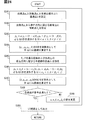
2本の経路線によるLC経路の生成処理について、図24を参照しつつ詳記すると、まずステップS341にて、出発点と到着点とを結ぶ線分上に、数式(4)に基づく通過点Xを設定し、ステップS342へと進む。ステップS342では、出発点から変更前車線の進行方向に延ばした半直線上に補助点X2を設定し、ステップS343へと進む。ステップS343では、数式(5)および数式(6)に基づく追加点p1,p2を設定し、ステップS344へと進む。ステップS344では、この4点[ps,p1,p2,X]を制御点として、B‐スプライン曲線を算定し、ステップS345へと進む。
The process of generating an LC route using two route lines will be described in detail with reference to FIG. 24. First, in step S341, a passing point based on the equation (4) is drawn on a line connecting the starting point and the arriving point. X is set, and the process proceeds to step S342. In step S342, the auxiliary point X2 is set on a semi-line extending from the departure point in the traveling direction of the pre-change lane, and the process proceeds to step S343. In step S343, it sets the
ステップS345では、補助点X3を設定し、ステップS346へと進む。ステップS346では、数式(7)および数式(8)に基づく追加点p3,p4を設定したのち、ステップS347へと進む。
In step S345, it sets the auxiliary point X 3, the process proceeds to step S346. At step S346, after setting the
ステップS347では、この4点[X,p3,p4,pf]を制御点としたB‐スプライン曲線を算定し、ステップS348へと進む。ステップS348では、2本のB‐スプライン曲線が、それぞれ走行経路の条件を満たしているか否かを判定する。条件を満たしていないと判定すると、ステップS349へと進み、a,α,β,α2,β2の値を変更し、ステップS341へと戻る。 In step S347, the four-point [X, p 3, p 4 , p f] was the control point B- calculated a spline curve, the process proceeds to step S348. In step S348, it is determined whether each of the two B-spline curves satisfies the condition of the traveling route. If it is determined that the condition is not satisfied, the flow proceeds to step S349, changes the values of a, α, β, α2, β2, and returns to step S341.
一方で、ステップS348にて各曲線が条件を満たすと判定すると、ステップS350へと進み、この2本の曲線からなる経路線をLC経路として出力し、図23のステップS360へと進む。 On the other hand, if it is determined in step S348 that each curve satisfies the condition, the process proceeds to step S350, a path line including the two curves is output as the LC route, and the process proceeds to step S360 in FIG.
ステップS360では、生成したLC経路への進行を開始してステップS370へと進む。ステップS370では、LCキャンセル経路を生成し、ステップS380へと進む。ステップS380では、LC経路とLCキャンセル経路のうち、自車両の進行する経路を選択し、ステップS390へと進む。ステップS390では、選択した経路の到着点(終点)に到着したか否かを判定する。終点に到着していない場合、ステップS370へと戻る。一方で、到着点に到着したと判定した場合には、一連の処理を終了する。 In step S360, the process proceeds to the generated LC path, and proceeds to step S370. In step S370, an LC cancellation route is generated, and the process proceeds to step S380. In step S380, a route in which the host vehicle travels is selected from the LC route and the LC cancel route, and the process proceeds to step S390. In step S390, it is determined whether or not the vehicle has arrived at the arrival point (end point) of the selected route. If not, the process returns to step S370. On the other hand, when it is determined that the vehicle has arrived at the arrival point, a series of processing ends.
第2実施形態の走行支援装置100は、車線変更の出発点と到着点とを結ぶ線分上に補助点を設定し、出発点を始点、補助点を終点とする補間曲線と、補助点を始点、到着点を終点とする補間曲線とを算定することにより、LC経路を生成する。これによれば、走行支援装置100は、変更前車線から変更先車線側へと向かってカーブ走行し、その後到着点に向かうにつれて直進走行へと復帰するような走行経路を生成できる。したがって、走行支援装置100は、車線変更により適したカーブ走行支援を実施できる。
The driving
走行支援装置100は、出発点から変更前車線に沿う方向に延ばした半直線と、終了点から変更先車線に沿う方向に延ばした半直線とが交わる場合には、出発点を始点、終了点を終点とした経路線を算定する。これによれば、走行支援装置100は、カーブ路等における車線変更に適した走行経路を生成可能である。
When the half-line extending from the starting point in the direction along the pre-change lane intersects with the half-line extending from the end point in the direction along the destination lane, the driving
走行支援装置100は、自車両が変更前車線に戻るLCキャンセル経路を算定するので、車線変更を中止して変更前車線に戻る場合に、より自車両のぶれを抑えつつ走行支援を行うことが可能となる。
The driving
(他の実施形態)
この明細書における開示は、例示された実施形態に制限されない。開示は、例示された実施形態と、それらに基づく当業者による変形態様を包含する。例えば、開示は、実施形態において示された部品および/または要素の組み合わせに限定されない。開示は、多様な組み合わせによって実施可能である。開示は、実施形態に追加可能な追加的な部分をもつことができる。開示は、実施形態の部品および/または要素が省略されたものを包含する。開示は、ひとつの実施形態と他の実施形態との間における部品および/または要素の置き換え、または組み合わせを包含する。開示される技術的範囲は、実施形態の記載に限定されない。開示されるいくつかの技術的範囲は、特許請求の範囲の記載によって示され、さらに特許請求の範囲の記載と均等の意味及び範囲内での全ての変更を含むものと解されるべきである。
(Other embodiments)
The disclosure in this specification is not limited to the illustrated embodiment. The disclosure includes the illustrated embodiments and variations based thereon based on those skilled in the art. For example, the disclosure is not limited to the combination of parts and / or elements shown in the embodiments. The disclosure can be implemented in various combinations. The disclosure may have additional parts that can be added to the embodiments. The disclosure encompasses embodiments that omit parts and / or elements. The disclosure encompasses the replacement or combination of parts and / or elements between one embodiment and another. The disclosed technical scope is not limited to the description of the embodiments. Some of the disclosed technical ranges are indicated by the description of the claims, and should be construed to include all modifications within the meaning and scope equivalent to the description of the claims. .
上述の実施形態において交差点右左折シーン、車線変更シーンについて説明したが、走行支援装置および走行支援方法は、自車両の旋回動作が必要となる種々のシーンで適用することができる。例えば走行支援装置および走行支援方法は、合流シーンにおける走行支援に適用してもよい。合流シーンにおける走行支援において、走行支援装置100は、例えば第2実施形態におけるLC経路の生成と同様に合流経路を生成すればよい。すなわち、走行支援装置100は、合流シーンを合流車線から本線への車線変更シーンとして走行経路を生成すればよい。なお、走行支援装置100は、本線の他車両同士の間隔が狭い等により、合流車線の終点に到着するまでに走行経路が生成できない場合、合流車線の他車両から所定距離離れており、且つ終点に近い地点にて自車両を停車させる。この場合走行支援装置100は、停車後に再度走行経路を生成する。
In the above embodiments, the intersection right / left turn scene and the lane change scene have been described. However, the driving support device and the driving support method can be applied to various scenes that require a turning operation of the own vehicle. For example, the driving support device and the driving support method may be applied to driving support in a merging scene. In the driving support in the merging scene, the driving
上述の実施形態において、走行支援方法は、車載ECUの処理部が実行するプログラムによって実現されるとした。これに代えて、例えば自車両を無線通信により管理するセンタによって処理の少なくとも一部が実行される構成であってもよい。また、複数の車載ECUが処理を分散して実行することにより走行支援方法を実現する構成であってもよい。 In the above-described embodiment, the driving support method is realized by a program executed by the processing unit of the vehicle-mounted ECU. Instead of this, for example, a configuration may be adopted in which at least a part of the processing is executed by a center that manages the own vehicle by wireless communication. Further, a configuration may be adopted in which a plurality of in-vehicle ECUs execute the processing in a distributed manner to realize the driving support method.
上述の実施形態において、走行支援装置および走行支援方法は、自動運転時のカーブ走行支援に適用されるとしたが、手動運転時のカーブ走行支援に適用されてもよい。例えば、走行が推奨される推奨経路をこれまで説明した方法で生成し、この推奨経路をHUD等によりドライバに提示することによってカーブ走行を支援してもよい。または、ドライバの運転による走行経路を評価する評価用経路をこれまで説明した方法により生成し、実際の走行経路が評価用経路から外れた場合にドライバに対してアドバイスを提示することによりカーブ走行を支援してもよい。 In the above-described embodiment, the driving support device and the driving support method are described as being applied to curve driving support during automatic driving, but may be applied to curve driving support during manual driving. For example, a recommended route for which traveling is recommended may be generated by the method described above, and the recommended route may be presented to the driver by using a HUD or the like to support curve driving. Alternatively, an evaluation route for evaluating the driving route by the driver's driving is generated by the method described above, and when the actual driving route deviates from the evaluation route, advice is provided to the driver to perform the curve driving, and You may help.
上述の実施形態のプロセッサは、1つまたは複数のCPU(Central Processing Unit)を含む処理部である。こうしたプロセッサは、CPUに加えて、GPU(Graphics Processing Unit)およびDFP(Data Flow Processor)等を含む処理部であってよい。さらにプロセッサは、FPGA(Field-Programmable Gate Array)、並びにAIの学習および推論等の特定処理に特化したIPコア等を含む処理部であってもよい。こうしたプロセッサの各演算回路部は、プリント基板に個別に実装された構成であってもよく、またはASIC(Application Specific Integrated Circuit)およびFPGA等に実装された構成であってもよい。 The processor according to the above-described embodiment is a processing unit including one or a plurality of CPUs (Central Processing Units). Such a processor may be a processing unit including a CPU (Graphics Processing Unit) and a DFP (Data Flow Processor) in addition to the CPU. Further, the processor may be a processing unit including an FPGA (Field-Programmable Gate Array) and an IP core specialized for specific processing such as AI learning and inference. Each arithmetic circuit unit of such a processor may be configured to be individually mounted on a printed board, or may be configured to be mounted on an ASIC (Application Specific Integrated Circuit), an FPGA, or the like.
制御プログラムを記憶するメモリ装置には、フラッシュメモリおよびハードディスク等の種々の非遷移的実体的記憶媒体(non-transitory tangible storage medium)が採用可能である。こうした記憶媒体の形態も、適宜変更されてよい。例えば記憶媒体は、メモリカード等の形態であり、車載ECUに設けられたスロット部に挿入されて、制御回路に電気的に接続される構成であってよい。 Various non-transitory tangible storage media such as a flash memory and a hard disk can be adopted as the memory device that stores the control program. The form of such a storage medium may be appropriately changed. For example, the storage medium may be in the form of a memory card or the like, and may be configured to be inserted into a slot provided in the in-vehicle ECU and electrically connected to the control circuit.
本開示に記載の制御部およびその手法は、コンピュータプログラムにより具体化された1つ乃至は複数の機能を実行するようにプログラムされたプロセッサを構成する専用コンピュータにより、実現されてもよい。あるいは、本開示に記載の装置およびその手法は、専用ハードウエア論理回路により、実現されてもよい。もしくは、本開示に記載の装置およびその手法は、コンピュータプログラムを実行するプロセッサと1つ以上のハードウエア論理回路との組み合わせにより構成された1つ以上の専用コンピュータにより、実現されてもよい。また、コンピュータプログラムは、コンピュータにより実行されるインストラクションとして、コンピュータ読み取り可能な非遷移有形記録媒体に記憶されていてもよい。 The control unit and the method thereof according to the present disclosure may be implemented by a dedicated computer configuring a processor programmed to execute one or more functions embodied by a computer program. Alternatively, the devices and techniques described in this disclosure may be implemented by dedicated hardware logic. Alternatively, the device and the technique described in the present disclosure may be realized by one or more dedicated computers configured by a combination of a processor executing a computer program and one or more hardware logic circuits. Further, the computer program may be stored in a computer-readable non-transitional tangible recording medium as instructions to be executed by a computer.
上述の実施形態における説明は、左側通行が法制化されている地域に対応したものであり、右側通行が法制化されている地域では、各走行シーンにおいて左右が逆になる。 The description in the above embodiment corresponds to an area where left-hand traffic is legislated, and in an area where right-hand traffic is legislated, left and right are reversed in each running scene.
100 走行支援装置(コンピュータ)、 101 プロセッサ、 S21、S22 ステップ(点設定部) S24、S25 ステップ(経路線算定部)、 S100 ステップ(カーブ走行支援部)。 100 Driving support device (computer), 101 processor, S21, S22 step (point setting unit) S24, S25 step (path line calculation unit), S100 step (curve driving support unit).
Claims (12)
少なくとも1つのプロセッサ(101)上において、
自車両をカーブ走行させる経路の始点および終点を設定し(S21)、
前記始点および前記終点を2頂点とする三角形を想定し(S22)、
前記三角形の2辺上にそれぞれ制御点を設定することにより、前記制御点、前記始点および前記終点を4頂点とする四角形を想定し(S24)、
前記四角形内に収まる経路線を算定し(S25)、
前記経路線に沿った自車両のカーブ走行を支援する(S100)、
というステップを含む走行支援方法。 A driving support method implemented by a computer (100) to support driving of the own vehicle,
On at least one processor (101),
The start point and the end point of the route on which the vehicle travels on a curve are set (S21).
Assuming a triangle having the start point and the end point as two vertices (S22),
By setting control points on two sides of the triangle, a quadrangle having the control point, the start point, and the end point as four vertices is assumed (S24).
A route line that fits within the rectangle is calculated (S25),
Assisting the vehicle to travel along a curve along the route line (S100);
A driving support method including the step of:
前記三角形を想定するステップでは、前記交差点への進入方向に前記始点から延びる半直線と、前記交差点からの退出方向の反対方向に前記終点から延びる半直線との交点に前記三角形の残りの頂点を設定する請求項1に記載の走行支援方法。 In supporting the travel of the own vehicle in turning right and left at an intersection,
In the step of assuming the triangle, the remaining vertices of the triangle at the intersection of a half line extending from the start point in the approach direction to the intersection and a half line extending from the end point in the direction opposite to the exit direction from the intersection. The driving support method according to claim 1, wherein the setting is performed.
前記経路線における対向車線を跨ぐ部分よりも前記始点側に、前記自車両の待機位置を設定する(S30)、というステップをさらに含む請求項1または請求項2に記載の走行支援方法。 In supporting the travel of the own vehicle in turning right and left at an intersection,
The driving support method according to claim 1 or 2, further comprising the step of: setting a standby position of the host vehicle at a position closer to the start point than a part of the route that straddles an oncoming lane (S30).
前記交差点内の進入不可エリアの位置情報を取得する(S231)、というステップをさらに含み、
前記四角形を想定するステップでは、各前記制御点を結ぶ線分と前記進入不可エリアとの距離が閾値以上となるように、前記制御点を設定する請求項1から請求項3のいずれか1項に記載の走行支援方法。 In supporting the travel of the own vehicle in turning right and left at an intersection,
Obtaining a position information of an inaccessible area in the intersection (S231);
4. The control point according to claim 1, wherein, in the step of assuming the quadrangle, the control point is set such that a distance between a line segment connecting the control points and the inaccessible area is equal to or greater than a threshold value. The driving support method described in the above.
前記経路線を第1の経路線とし、
前記始点を第1の始点とし、
前記第1の経路線における前記第1の始点から所定の距離直進した地点を第2の始点とし、
前記第2の始点を通る第2の経路線を算定し(S63)、
前記第1の始点と前記第2の始点との間の区間に、前記第2の経路線を走行する場合の待機位置を設定する(S62)、
というステップをさらに含む請求項1から請求項4のいずれか1項に記載の走行支援方法。 In supporting the travel of the own vehicle in turning right and left at an intersection,
The path line is a first path line,
The starting point is a first starting point,
A point on the first route that has traveled a predetermined distance straight from the first start point is defined as a second start point,
A second path line passing through the second start point is calculated (S63),
In a section between the first start point and the second start point, a standby position for traveling on the second route line is set (S62).
The driving support method according to any one of claims 1 to 4, further comprising the step of:
カーブ走行を支援するステップでは、前記対向車が無いと判定した場合に前記第1の経路線に沿ったカーブ走行を支援し、前記対向車が有ると判定した場合に前記第2の経路線に沿ったカーブ走行を支援する請求項5に記載の走行支援方法。 Determining the presence or absence of an oncoming vehicle,
In the step of supporting a curve traveling, when it is determined that the oncoming vehicle is not present, the vehicle assists the curve traveling along the first route line, and when it is determined that the oncoming vehicle is present, the vehicle travels along the second route line. The traveling support method according to claim 5, which supports traveling along a curved road.
前記対向車線が無いと判定した場合には、前記第2の経路線の算定を中断する(S90)、
というステップをさらに含む請求項5または請求項6に記載の走行支援方法。 It is determined whether there is an oncoming lane (S40),
When it is determined that the oncoming lane does not exist, the calculation of the second route is interrupted (S90).
7. The driving support method according to claim 5, further comprising the step of:
車線変更の出発点と到着点とを設定し(S320)、
前記出発点と前記到着点とを結ぶ線上に前記自車両の通過点を設定する(S341)、
というステップをさらに含み、
前記始点および前記終点を設定するステップでは、前記出発点を第1の始点、前記通過点を第1の終点且つ第2の始点に設定し、前記到着点を第2の終点に設定し、
前記三角形を想定するステップでは、前記第1の始点、前記第1の終点、および前記第1の始点から進行方向前方に延びる半直線上の点を3頂点とする第1の三角形と、前記第2の始点、前記第2の終点、および前記第2の終点から進行方向後方に延びる半直線上の点を3頂点とする第2の三角形とを想定し、
前記経路線を算定するステップでは、前記第1の始点と前記第1の終点との間の第1の経路線、および前記第2の始点と前記第2の終点との間の第2の経路線とを算定する請求項1から請求項4のいずれか1項に記載の走行支援方法。 In supporting the travel of the own vehicle that performs lane change,
The start point and the arrival point of the lane change are set (S320),
A passing point of the own vehicle is set on a line connecting the departure point and the arrival point (S341).
Further comprising the step of
In the step of setting the start point and the end point, the start point is set as a first start point, the passing point is set as a first end point and a second start point, and the arrival point is set as a second end point;
In the step of assuming the triangle, a first triangle having three vertices on a first straight line extending from the first start point, the first end point, and the first start point in a traveling direction; Assuming a second triangle having three vertices as a starting point of 2, the second end point, and a point on a semi-line extending rearward in the traveling direction from the second end point,
In the step of calculating the path line, a first path line between the first start point and the first end point, and a second path line between the second start point and the second end point The driving support method according to any one of claims 1 to 4, wherein a line is calculated.
前記半直線同士が交わると判定すると、前記出発点を前記始点、前記到着点を前記終点とした前記経路線を算定する(S355)、
というステップをさらに含む請求項8に記載の走行支援方法。 It is determined whether a ray extending forward from the departure point in the traveling direction intersects a ray extending rearward from the arrival point in the traveling direction (S330).
If it is determined that the half-lines intersect, the route line with the departure point as the start point and the arrival point as the end point is calculated (S355).
The driving support method according to claim 8, further comprising the step of:
前記三角形の2辺上にそれぞれ制御点を設定することにより、前記制御点、前記始点および前記終点を4頂点とする四角形を想定し、四角形内に収まる経路線を算定する経路線算定部(S24、S25)と、
前記経路線に沿った自車両のカーブ走行を支援するカーブ走行支援部(S100)と、
を備える走行支援装置。 A point setting unit (S21, S22) for setting a starting point and an ending point of a route on which the vehicle travels on a curve, and assuming a triangle having the starting point and the ending point as two vertices;
By setting a control point on each of two sides of the triangle, a route line calculation unit (S24) that assumes a square having the control point, the start point, and the end point as four vertices, and calculates a route line that falls within the square. , S25),
A curve traveling support unit (S100) for supporting a curve traveling of the own vehicle along the route line;
A driving assistance device comprising:
Priority Applications (1)
| Application Number | Priority Date | Filing Date | Title |
|---|---|---|---|
| US16/545,699 US11181920B2 (en) | 2018-08-28 | 2019-08-20 | Travel assistance method and travel assistance apparatus |
Applications Claiming Priority (2)
| Application Number | Priority Date | Filing Date | Title |
|---|---|---|---|
| JP2018159610 | 2018-08-28 | ||
| JP2018159610 | 2018-08-28 |
Publications (2)
| Publication Number | Publication Date |
|---|---|
| JP2020032994A true JP2020032994A (en) | 2020-03-05 |
| JP7192610B2 JP7192610B2 (en) | 2022-12-20 |
Family
ID=69666850
Family Applications (1)
| Application Number | Title | Priority Date | Filing Date |
|---|---|---|---|
| JP2019061696A Active JP7192610B2 (en) | 2018-08-28 | 2019-03-27 | Driving support method and driving support device |
Country Status (1)
| Country | Link |
|---|---|
| JP (1) | JP7192610B2 (en) |
Cited By (4)
| Publication number | Priority date | Publication date | Assignee | Title |
|---|---|---|---|---|
| US20200341466A1 (en) * | 2019-04-26 | 2020-10-29 | Nvidia Corporation | Intersection pose detection in autonomous machine applications |
| JP2021157591A (en) * | 2020-03-27 | 2021-10-07 | パイオニア株式会社 | Information processor |
| CN114495554A (en) * | 2021-12-31 | 2022-05-13 | 武汉中海庭数据技术有限公司 | Intersection guide information construction method and system for intelligent driving |
| JP7433091B2 (en) | 2020-03-10 | 2024-02-19 | 日産自動車株式会社 | Travel route setting method and travel route setting device |
Citations (9)
| Publication number | Priority date | Publication date | Assignee | Title |
|---|---|---|---|---|
| US20080255728A1 (en) * | 2005-12-09 | 2008-10-16 | Hella Kgaa Hueck & Co. | Path Planning |
| JPWO2011155030A1 (en) * | 2010-06-08 | 2013-08-01 | トヨタ自動車株式会社 | Travel model creation device and driving support device |
| JP2017010292A (en) * | 2015-06-23 | 2017-01-12 | 株式会社明電舎 | Agv orbit calculation device and method |
| JP2017033060A (en) * | 2015-07-29 | 2017-02-09 | トヨタ自動車株式会社 | Vehicle drive support control device |
| WO2017056726A1 (en) * | 2015-09-30 | 2017-04-06 | 日立オートモティブシステムズ株式会社 | Lane change system |
| WO2017077598A1 (en) * | 2015-11-04 | 2017-05-11 | 日産自動車株式会社 | Autonomous vehicle operation apparatus and autonomous vehicle operation method |
| JP2017165156A (en) * | 2016-03-14 | 2017-09-21 | 本田技研工業株式会社 | Vehicle control system, vehicle control method and vehicle control program |
| JP2018002082A (en) * | 2016-07-07 | 2018-01-11 | アルパイン株式会社 | Movement route generating apparatus and movement route generating method |
| JPWO2017014012A1 (en) * | 2015-07-22 | 2018-03-08 | 本田技研工業株式会社 | Route generation device, route generation method, and route generation program |
Family Cites Families (2)
| Publication number | Priority date | Publication date | Assignee | Title |
|---|---|---|---|---|
| JP2011155030A (en) | 2010-01-26 | 2011-08-11 | Disco Abrasive Syst Ltd | Wafer holding mechanism |
| JP6643921B2 (en) | 2015-07-02 | 2020-02-12 | オークラ輸送機株式会社 | Sorting device and article removal method |
-
2019
- 2019-03-27 JP JP2019061696A patent/JP7192610B2/en active Active
Patent Citations (9)
| Publication number | Priority date | Publication date | Assignee | Title |
|---|---|---|---|---|
| US20080255728A1 (en) * | 2005-12-09 | 2008-10-16 | Hella Kgaa Hueck & Co. | Path Planning |
| JPWO2011155030A1 (en) * | 2010-06-08 | 2013-08-01 | トヨタ自動車株式会社 | Travel model creation device and driving support device |
| JP2017010292A (en) * | 2015-06-23 | 2017-01-12 | 株式会社明電舎 | Agv orbit calculation device and method |
| JPWO2017014012A1 (en) * | 2015-07-22 | 2018-03-08 | 本田技研工業株式会社 | Route generation device, route generation method, and route generation program |
| JP2017033060A (en) * | 2015-07-29 | 2017-02-09 | トヨタ自動車株式会社 | Vehicle drive support control device |
| WO2017056726A1 (en) * | 2015-09-30 | 2017-04-06 | 日立オートモティブシステムズ株式会社 | Lane change system |
| WO2017077598A1 (en) * | 2015-11-04 | 2017-05-11 | 日産自動車株式会社 | Autonomous vehicle operation apparatus and autonomous vehicle operation method |
| JP2017165156A (en) * | 2016-03-14 | 2017-09-21 | 本田技研工業株式会社 | Vehicle control system, vehicle control method and vehicle control program |
| JP2018002082A (en) * | 2016-07-07 | 2018-01-11 | アルパイン株式会社 | Movement route generating apparatus and movement route generating method |
Cited By (4)
| Publication number | Priority date | Publication date | Assignee | Title |
|---|---|---|---|---|
| US20200341466A1 (en) * | 2019-04-26 | 2020-10-29 | Nvidia Corporation | Intersection pose detection in autonomous machine applications |
| JP7433091B2 (en) | 2020-03-10 | 2024-02-19 | 日産自動車株式会社 | Travel route setting method and travel route setting device |
| JP2021157591A (en) * | 2020-03-27 | 2021-10-07 | パイオニア株式会社 | Information processor |
| CN114495554A (en) * | 2021-12-31 | 2022-05-13 | 武汉中海庭数据技术有限公司 | Intersection guide information construction method and system for intelligent driving |
Also Published As
| Publication number | Publication date |
|---|---|
| JP7192610B2 (en) | 2022-12-20 |
Similar Documents
| Publication | Publication Date | Title |
|---|---|---|
| US11181920B2 (en) | Travel assistance method and travel assistance apparatus | |
| CN109583151B (en) | Method and device for predicting running track of vehicle | |
| JP7192610B2 (en) | Driving support method and driving support device | |
| US10459441B2 (en) | Method and system for operating autonomous driving vehicles based on motion plans | |
| JP6273976B2 (en) | Display control device for vehicle | |
| JP6819788B2 (en) | Driving support method and driving support device | |
| JP6809611B2 (en) | Driving support method and driving support device | |
| CN110758381B (en) | Method and device for generating steering track, storage medium and electronic equipment | |
| CN109823342B (en) | Vehicle intersection driving method, device and terminal | |
| JP2018138404A (en) | Vehicle driving assisting system and method | |
| JP2022502311A (en) | Feature point extraction method and equipment for environmental targets | |
| JP2018138402A (en) | Vehicle driving assisting system and method | |
| US20210188308A1 (en) | A qp spline path and spiral path based reference line smoothing method for autonomous driving | |
| JP6297482B2 (en) | Information processing device | |
| JP2020125988A (en) | Entrance lane estimation system, entrance lane estimation method, and entrance lane estimation program | |
| JP6607526B2 (en) | Vehicle driving support system and method | |
| JP7129495B2 (en) | Driving support method and driving support device | |
| JP2018138406A (en) | Vehicle driving assisting system and method | |
| JP6838769B2 (en) | Surrounding environment recognition device, display control device | |
| WO2021166425A1 (en) | Travel assistance device, travel assistance method, and travel assistance program | |
| EP3985641B1 (en) | Travel assistance method and travel assistance device | |
| JP7003512B2 (en) | Vehicle driving control method and equipment | |
| WO2022153701A1 (en) | Traveling assistance device and traveling assistance method | |
| JP7374722B2 (en) | Driving support method and driving support device | |
| JP7468783B2 (en) | On-board device, server, driving assistance implementation program, auxiliary sign utilization data transmission program, map data update program, and driving control method |
Legal Events
| Date | Code | Title | Description |
|---|---|---|---|
| A621 | Written request for application examination |
Free format text: JAPANESE INTERMEDIATE CODE: A621 Effective date: 20210716 |
|
| A977 | Report on retrieval |
Free format text: JAPANESE INTERMEDIATE CODE: A971007 Effective date: 20220427 |
|
| A131 | Notification of reasons for refusal |
Free format text: JAPANESE INTERMEDIATE CODE: A131 Effective date: 20220510 |
|
| A521 | Request for written amendment filed |
Free format text: JAPANESE INTERMEDIATE CODE: A523 Effective date: 20220628 |
|
| TRDD | Decision of grant or rejection written | ||
| A01 | Written decision to grant a patent or to grant a registration (utility model) |
Free format text: JAPANESE INTERMEDIATE CODE: A01 Effective date: 20221108 |
|
| A61 | First payment of annual fees (during grant procedure) |
Free format text: JAPANESE INTERMEDIATE CODE: A61 Effective date: 20221121 |
|
| R151 | Written notification of patent or utility model registration |
Ref document number: 7192610 Country of ref document: JP Free format text: JAPANESE INTERMEDIATE CODE: R151 |