JP2020031392A - Communication device, control method of the same, and program - Google Patents
Communication device, control method of the same, and program Download PDFInfo
- Publication number
- JP2020031392A JP2020031392A JP2018157447A JP2018157447A JP2020031392A JP 2020031392 A JP2020031392 A JP 2020031392A JP 2018157447 A JP2018157447 A JP 2018157447A JP 2018157447 A JP2018157447 A JP 2018157447A JP 2020031392 A JP2020031392 A JP 2020031392A
- Authority
- JP
- Japan
- Prior art keywords
- mfp
- access point
- wireless communication
- communication
- direct wireless
- Prior art date
- Legal status (The legal status is an assumption and is not a legal conclusion. Google has not performed a legal analysis and makes no representation as to the accuracy of the status listed.)
- Pending
Links
Images


Classifications
-
- Y—GENERAL TAGGING OF NEW TECHNOLOGICAL DEVELOPMENTS; GENERAL TAGGING OF CROSS-SECTIONAL TECHNOLOGIES SPANNING OVER SEVERAL SECTIONS OF THE IPC; TECHNICAL SUBJECTS COVERED BY FORMER USPC CROSS-REFERENCE ART COLLECTIONS [XRACs] AND DIGESTS
- Y02—TECHNOLOGIES OR APPLICATIONS FOR MITIGATION OR ADAPTATION AGAINST CLIMATE CHANGE
- Y02D—CLIMATE CHANGE MITIGATION TECHNOLOGIES IN INFORMATION AND COMMUNICATION TECHNOLOGIES [ICT], I.E. INFORMATION AND COMMUNICATION TECHNOLOGIES AIMING AT THE REDUCTION OF THEIR OWN ENERGY USE
- Y02D10/00—Energy efficient computing, e.g. low power processors, power management or thermal management
-
- Y—GENERAL TAGGING OF NEW TECHNOLOGICAL DEVELOPMENTS; GENERAL TAGGING OF CROSS-SECTIONAL TECHNOLOGIES SPANNING OVER SEVERAL SECTIONS OF THE IPC; TECHNICAL SUBJECTS COVERED BY FORMER USPC CROSS-REFERENCE ART COLLECTIONS [XRACs] AND DIGESTS
- Y02—TECHNOLOGIES OR APPLICATIONS FOR MITIGATION OR ADAPTATION AGAINST CLIMATE CHANGE
- Y02D—CLIMATE CHANGE MITIGATION TECHNOLOGIES IN INFORMATION AND COMMUNICATION TECHNOLOGIES [ICT], I.E. INFORMATION AND COMMUNICATION TECHNOLOGIES AIMING AT THE REDUCTION OF THEIR OWN ENERGY USE
- Y02D30/00—Reducing energy consumption in communication networks
- Y02D30/70—Reducing energy consumption in communication networks in wireless communication networks
Landscapes
- Facsimiles In General (AREA)
- Mobile Radio Communication Systems (AREA)
- Accessory Devices And Overall Control Thereof (AREA)
Abstract
Description
本発明は、通信装置及びその制御方法、並びにプログラムに関する。 The present invention relates to a communication device, a control method thereof, and a program.
無線通信を行う通信装置としてのMFP(Multifunction Peripheral)が知られている。MFPは、無線LANを構成する外部装置と所定のアクセスポイントを介して無線通信(以下、「無線LAN通信」という。)を行う。また、MFPは、上記所定のアクセスポイントを介すことなく、外部装置とWi−Fi Allianceによって定められたWi−Fi Direct規格によって無線通信(以下、「ダイレクト無線通信」という。)を行う(例えば、特許文献1参照)。ダイレクト無線通信では、MFPがアクセスポイントとして動作する。MFPでは、ユーザがMFPの操作部でダイレクト無線通信の有効化を設定すると、例えば、ユーザが所持する携帯端末とMFPとの間でダイレクト無線通信が開始される。また、ユーザが上記操作部でダイレクト無線通信の無効化を設定すると、上記携帯端末とMFPとの間のダイレクト無線通信が終了する。 An MFP (Multifunction Peripheral) is known as a communication device that performs wireless communication. The MFP performs wireless communication with an external device configuring the wireless LAN via a predetermined access point (hereinafter, referred to as “wireless LAN communication”). Further, the MFP performs wireless communication (hereinafter, referred to as "direct wireless communication") with an external device according to the Wi-Fi Direct standard defined by the Wi-Fi Alliance without passing through the predetermined access point. And Patent Document 1). In direct wireless communication, the MFP operates as an access point. In the MFP, when the user sets the activation of the direct wireless communication using the operation unit of the MFP, for example, the direct wireless communication is started between the portable terminal owned by the user and the MFP. When the user sets the invalidation of the direct wireless communication using the operation unit, the direct wireless communication between the portable terminal and the MFP ends.
ところで、MFPは、ダイレクト無線通信においてアクセスポイントとして動作する場合、無線通信の国際規格であるIEEE802.11で規定されたクライアント側の省電力動作を保障するために無線ビーコンを受信し続ける必要がある。これに対して、MFPは、ダイレクト無線通信の設定が有効化されてから無効化に切り替えられるまでの間、省電力状態に移行せず、通常状態を維持する。このようなMFPは、ダイレクト無線通信によるデータの送受信を完了しても、ユーザが無線ダイレクトの設定を無効化に切り替え忘れると、通常状態を維持し続け、電力を不要に消費してしまう。これに対し、従来では、MFPは、ダイレクト無線通信を開始してから予め設定された所定の時間が経過した際に当該ダイレクト無線通信を強制的に終了する(例えば、特許文献2参照)。 By the way, when the MFP operates as an access point in direct wireless communication, it is necessary to continuously receive a wireless beacon in order to guarantee a power saving operation on the client side defined by IEEE 802.11 which is an international standard for wireless communication. . On the other hand, the MFP does not shift to the power saving state and maintains the normal state from the time when the setting of the direct wireless communication is enabled to the time when the setting is switched to the invalidation. Even if the transmission and reception of data by direct wireless communication are completed, if the user forgets to switch the setting of wireless direct to invalid, the MFP continues to maintain the normal state and consumes power unnecessarily. On the other hand, conventionally, the MFP forcibly terminates the direct wireless communication when a predetermined period of time has elapsed since the start of the direct wireless communication (for example, see Patent Document 2).
しかしながら、上述したように、ダイレクト無線通信を開始してから上記所定の時間が経過した際に当該ダイレクト無線通信を強制的に終了すると、電力の不要な消費を防止できても、通信中にダイレクト無線通信を利用できなくなることがある。例えば、或る程度の送信時間を要する程データ量の大きい印刷データをダイレクト無線通信によって携帯端末から受信する場合、当該印刷データの受信を完了する前に上記所定の時間が経過してしまうことがある。この場合、印刷データの受信の途中でダイレクト無線通信が利用できなくなる。その結果、上記印刷データを用いたプリントジョブを実行できなくなるという問題が生じる。 However, as described above, if the direct wireless communication is forcibly terminated when the predetermined time has elapsed since the start of the direct wireless communication, even if unnecessary consumption of power can be prevented, the direct wireless communication is not performed during the communication. Wireless communication may not be available. For example, when print data having a data amount large enough to require a certain transmission time is received from a mobile terminal by direct wireless communication, the predetermined time may elapse before the reception of the print data is completed. is there. In this case, the direct wireless communication cannot be used during the reception of the print data. As a result, there arises a problem that a print job using the print data cannot be executed.
本発明の目的は、ダイレクト無線通信が途中で利用できなくなるのを防止することができる通信装置及びその制御方法、並びにプログラムを提供することにある。 An object of the present invention is to provide a communication device, a control method thereof, and a program capable of preventing direct wireless communication from being unavailable halfway.
上記目的を達成するために、本発明の通信装置は、アクセスポイントとして動作して外部装置とダイレクト無線通信を行う通信装置において、前記アクセスポイントとしての動作の開始に従って計時する計時手段と、前記計時手段による計時の結果が所定の条件を満たし且つ前記アクセスポイントを介する所定の通信が前記外部装置と行われていないことに基づいて前記アクセスポイントとしての動作を停止させる停止制御手段とを備えることを特徴とする。 In order to achieve the above object, a communication device of the present invention is a communication device that operates as an access point and performs direct wireless communication with an external device. Stopping control means for stopping the operation as the access point based on the result of the clocking by the means satisfying a predetermined condition and the predetermined communication via the access point not being performed with the external device. Features.
本発明によれば、ダイレクト無線通信が途中で利用できなくなるのを防止することができる。 According to the present invention, it is possible to prevent the direct wireless communication from becoming unavailable halfway.
以下、本発明の実施の形態について図面を参照しながら詳述する。なお、本実施の形態では、通信装置としてのMFPに本発明を適用した場合について説明するが、本発明は通信装置に限られず、ダイレクト無線通信によって各種データを送受信するプリンタやスキャナ等の画像形成装置に本発明を適用してもよい。 Hereinafter, embodiments of the present invention will be described in detail with reference to the drawings. In the present embodiment, a case will be described in which the present invention is applied to an MFP as a communication device. However, the present invention is not limited to a communication device, and an image forming apparatus such as a printer or a scanner that transmits and receives various data by direct wireless communication. The present invention may be applied to an apparatus.
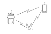
図1は、本発明の実施の形態に係る通信装置としてのMFP1による無線通信を説明するための図である。 FIG. 1 is a diagram illustrating wireless communication by MFP 1 as a communication device according to an embodiment of the present invention.
図1において、MFP1は、有線LANを構成する外部装置と有線LAN通信を行う。また、MFP1は、インフラストラクチャモードやアドホックモード等の無線通信機能を備える。インフラストラクチャモードでは、MFP1は、無線LANを構成する外部装置と無線アクセスポイント2を介して無線LAN通信を行う。アドホックモードでは、MFP1は、該MFP1をアクセスポイントとして動作させることで、無線アクセスポイント2を介すことなく、携帯端末3等とダイレクト無線通信を行う。アドホックモードでは、MFP1が「Group Owner」として機能し、ダイレクト無線通信におけるアクセスポイントとして動作する。また、携帯端末3が「Client」として機能し、ダイレクト無線通信におけるMFP1のクライアントとして動作する。なお、アドホックモードでの接続形態は、1対1若しくは1対複数の関係で、Group OwnerとClientとが接続可能なものとする。
In FIG. 1, an MFP 1 performs wired LAN communication with an external device configuring a wired LAN. Further, the MFP 1 has a wireless communication function such as an infrastructure mode or an ad hoc mode. In the infrastructure mode, the MFP 1 performs wireless LAN communication with an external device configuring the wireless LAN via the
図2は、図1のMFP1のハードウェア構成を概略的に示すブロック図である。図2において、MFP1は、コントローラ10、操作部109、スキャナ110、プリンタ111、及び電源部120を備える。コントローラ10は、操作部109、スキャナ110、プリンタ111、及び電源部120と接続されている。また、コントローラ10は、CPU101、RAM102、EEPROM103、RTC104(計時手段)、操作部I/F105、スキャナI/F106、プリンタI/F107、ネットワークI/F108、有線LAN制御部112、及び無線LAN制御部113を備える。なお、CPUは、Central Processing Unitの略称である。RAMは、Random Access Memoryの略称である。EEPROMは、Electrically Erasable Programmable Read−Only Memoryの略称である。RTCは、Real Time Clockの略称である。CPU101、RAM102、EEPROM103、RTC104、操作部I/F105、スキャナI/F106、プリンタI/F107、及びネットワークI/F108は、システムバス114を介して互いに接続されている。有線LAN制御部112及び無線LAN制御部113は、ネットワークI/F108と接続されている。
FIG. 2 is a block diagram schematically showing a hardware configuration of MFP 1 in FIG. 2, the MFP 1 includes a
CPU101は、MFP1全体の動作を制御する。CPU101は、EEPROM103に記憶されたプログラムに従って、システムバス114に接続される各デバイスを統括的に制御する。RAM102は、CPU101の主メモリ又はワークエリア等として機能する。また、RAM102は、画像情報の蓄積領域として用いられる。EEPROM103は、CPU101によって実行される制御プログラムや各種データを格納する。RTC104は、時計であり、MFP1の時間機能を制御する。操作部I/F105は、コントローラ10及び操作部109の間の通信を制御する。操作部109は、キーボード等の入力装置(不図示)やディスプレイ等の表示装置(不図示)を備える。
スキャナI/F106は、コントローラ10及びスキャナ110の間の通信を制御する。スキャナ110は、スキャナエンジンである。スキャナ110は、配置された原稿を読み取って画像データを生成する。プリンタI/F107は、コントローラ10及びプリンタ111の間の通信を制御する。プリンタ111は、プリンタエンジンである。プリンタ111は、スキャナ110が生成した画像データ等を用紙に印刷する。ネットワークI/F108は、有線LAN制御部112及び無線LAN制御部113による通信を制御する。有線LAN制御部112及び無線LAN制御部113は、NIC(Network Interface Controller)である。有線LAN制御部112は、外部装置との有線LAN通信を制御する。無線LAN制御部112は、インフラストラクチャモード及びアドホックモードの何れかによる外部装置との無線通信を制御する。
The scanner I / F 106 controls communication between the
電源部120は、コントローラ10、操作部I/F105、スキャナI/F106、及びプリンタI/F107といったデバイスへ電力を供給する。電源部120は、CPU101からの指示に応じて上記各デバイスへの電力の供給量を調整してMFP1の電力状態を制御する。例えば、電源部120は、MFP1の電源ON/OFF制御、通常状態から省電力状態への移行制御、省電力状態から通常状態への復帰制御を行う。なお、本実施の形態では、コントローラ10が、有線LAN制御部112及び無線LAN制御部113へ電力を供給する。
The
図3は、図1の操作部109に表示されるホーム画面300の一例を示す図である。ホーム画面300は、MFP1に搭載される複数の機能の中から利用する機能をユーザに選択させるための画面である。例えば、ホーム画面300において、ユーザが項目301を選択すると、MFP1は、ユーザに指定された携帯端末3と後述する図5の無線ダイレクト接続処理を実行する。無線ダイレクト接続処理により、携帯端末3とダイレクト無線通信を行うための無線ダイレクト接続を確立すると、MFP1は、図4の無線ダイレクト接続画面400を操作部109に表示する。
FIG. 3 is a diagram showing an example of the
無線ダイレクト接続画面400は、接続状態情報401、SSID(Service Set Identifier)402、ネットワークキー403、及び接続終了ボタン404で構成される。接続状態情報401は、無線ダイレクト接続の状態に関する情報である。無線ダイレクト接続画面400には、接続状態情報401として、例えば、無線ダイレクト未接続状態であることを示す「無線ダイレクト 端末接続待ち」や、無線ダイレクト接続状態であることを示す「無線ダイレクト 接続中」が表示される。SSID402は、携帯端末3がMFP1とダイレクト無線通信を行う際に必要となるMFP1の識別IDである。ネットワークキー403は、携帯端末3がMFP1とダイレクト無線通信を行う際に必要となるパスワード情報である。携帯端末3は、無線ダイレクト接続画面400におけるSSID402及びネットワークキー403の各値を指定することで、アクセスポイントとして機能するMFP1とダイレクト無線通信可能となる。接続終了ボタン404は、無線ダイレクト接続の終了を指示するためのボタンである。無線ダイレクト接続画面400において、ユーザが接続終了ボタン404を選択すると、MFP1は、携帯端末3との無線ダイレクト接続を切断する。さらに、MFP1は、操作部109に表示された無線ダイレクト接続画面400をホーム画面300に切り替える。
The wireless
図5は、図1のMFP1及び携帯端末3によって実行される無線ダイレクト接続処理の手順を示すシーケンス図である。図5の処理は、例えば、ホーム画面300においてユーザが項目301を選択した際に実行される。
FIG. 5 is a sequence diagram illustrating a procedure of the wireless direct connection process executed by the MFP 1 and the mobile terminal 3 in FIG. 5 is executed, for example, when the user selects the
図5において、まず、MFP1及び携帯端末3は、通信相手を検出するための機器探索を行う(ステップS501)。互いに通信相手を検出すると、MFP1は、MFP1及び携帯端末3の各々のダイレクト無線通信における役割を決定する(ステップS502)。具体的に、MFP1は、MFP1を「Group Owner」に決定し、携帯端末3を「Client」に決定する。次いで、MFP1は、Wi−Fi Allianceにより定められたWPS(Wi−Fi Protected Setup)を用いて、携帯端末3とダイレクト無線通信を行うためのパラメータの共有を行う(ステップS503)。上記パラメータは、例えば、無線ダイレクト接続画面400のSSID402の値やネットワークキー403の値を含む。これにより、MFP1をアクセスポイントとする無線ネットワークが構築される。
In FIG. 5, first, the MFP 1 and the mobile terminal 3 perform a device search for detecting a communication partner (step S501). Upon detecting the communication partner, the MFP 1 determines the roles of the MFP 1 and the portable terminal 3 in direct wireless communication (step S502). Specifically, the MFP 1 determines the MFP 1 as “Group Owner” and determines the mobile terminal 3 as “Client”. Next, the MFP 1 uses the WPS (Wi-Fi Protected Setup) defined by the Wi-Fi Alliance to share parameters for performing direct wireless communication with the mobile terminal 3 (step S503). The parameters include, for example, the value of the
次いで、MFP1は、共有したパラメータを用いて、携帯端末3とセキュア接続を行う(ステップS504)。次いで、MFP1は、DHCPサーバとして動作して、上記無線ネットワークにおける携帯端末3のIPアドレスを携帯端末3に付与する(ステップS505)。MFP1は、当該IPアドレスを指定することで、無線アクセスポイント2を介すことなく、上記無線ネットワークにおいて携帯端末3とダイレクト無線通信を行うことが可能となる。本実施の形態では、MFP1は、ダイレクト無線通信により、MFP1の消耗品の残量やMFP1の稼働状況等の状態情報を携帯端末3に送信する。また、MFP1は、ダイレクト無線通信により、プリントジョブを実行するための印刷データ(ジョブデータ)を携帯端末3から受信する。印刷データは、RFC2910やRFC2911で定められたIPP(Internet Printing Protocol)等のインターネット印刷プロトコルを使用して送受信されるデータである。印刷データでは、「Create−Job」でプリントジョブの開始が宣言され、「Close−Job」でプリントジョブの終了が宣言される。実際に印刷する描画データは、「Send−Documet」で送受信するものとし、MFP1がプリンタ111を介して印刷するタイミングは、IPP通信とは同期なしに行われる。
Next, the MFP 1 makes a secure connection with the mobile terminal 3 using the shared parameters (step S504). Next, the MFP 1 operates as a DHCP server, and gives the IP address of the mobile terminal 3 in the wireless network to the mobile terminal 3 (Step S505). By specifying the IP address, the MFP 1 can perform direct wireless communication with the portable terminal 3 in the wireless network without passing through the
図6は、図1のMFP1によって実行される省電力制御処理の手順を示すフローチャートである。図6の処理は、CPU101がEEPROM103に格納されたプログラムを実行することによって行われる。図6の処理は、MFP1が起動した後、所定の間隔で実行される。
FIG. 6 is a flowchart illustrating a procedure of power saving control processing executed by MFP 1 in FIG. 6 is performed by the
図6において、CPU101は、MFP1の省電力状態移行条件を満たしたか否かを判別する(ステップS601)。省電力状態移行条件は、例えば、予め設定された所定の期間の間に操作部109でオペレータによる操作を受け付けないこと、又は上記所定の期間の間にジョブが実行されないことである。
In FIG. 6, the
ステップS601の判別の結果、MFP1の省電力状態移行条件を満たし、さらに、MFP1が無線通信を行っているとき、CPU101は、上記無線通信が無線LAN通信及びダイレクト無線通信の何れであるかを判別する(ステップS602)。
As a result of the determination in step S601, when the power saving state transition condition of the MFP 1 is satisfied and the MFP 1 is performing wireless communication, the
ステップS602の判別の結果、上記無線通信がダイレクト無線通信であるとき、CPU101は、本処理を終了する。すなわち、MFP1は、当該MFP1がアクセスポイントとして動作する場合、省電力状態に移行しない。
If the result of determination in step S602 is that the wireless communication is direct wireless communication, the
ステップS602の判別の結果、上記無線通信が無線LAN通信であるとき、CPU101は、上記無線通信をパワーセーブモードで行うように制御する(ステップS603)。ステップS603では、CPU101は、ビーコンが送信されると予想されるタイミングの前後で受信機(不図示)を動作させ、そのタイミング以外では受信機への給電を停止することで、消費電力を低減させる。
If the result of determination in step S602 is that the wireless communication is wireless LAN communication, the
具体的に、ステップS603では、MFP1が、IEEE802.11で規定されたPMビットを用いて、無線アクセスポイント2にMFP1がパワーセーブモードへ移行することを通知する。その後、MFP1は、無線アクセスポイント2から受信したビーコンに含まれるTIM(Traffic Indication Map)を解析して、無線アクセスポイント2にMFP1宛てのデータがバッファリングされているか否かを判別する。無線アクセスポイント2にMFP1宛てのデータがバッファリングされている場合、MFP1は、無線LAN制御部113の給電を継続し、PS‐Pollパケットを無線アクセスポイント2に送信する。PS‐Pollパケットを受信した無線アクセスポイント2は、MFP1が受信可能な状態(Awake)であると判別し、バッファリングしているデータをMFP1に送信する。データパケットを受信したMFP1は、その旨を示すACKパケットを無線アクセスポイント2に送信する。MFP1は、受信したパケットのMACヘッダに含まれるMore Dataフラグに基づいてAwakeを維持するか否かを判別する。例えば、More Dataフラグが「1」である場合、MFP1はAwakeを維持する。一方、More Dataフラグが「0」である場合、MFP1は、無線LAN制御部113の給電を停止し、無線LAN制御部113を通信不可能な状態(Doze)に移行させる。
Specifically, in step S603, the MFP 1 notifies the
次いで、CPU101は、コントローラ10に含まれる一部のデバイスを省電力モードへ移行させる(ステップS604)。具体的に、CPU101は、電源部120から操作部I/F105、スキャナI/F106、及びプリンタI/F107への電力の供給を停止する。これにより、MFP1では、操作部109、スキャナ110、及びプリンタ111への電力の供給も停止される。次いで、CPU101は、コントローラ10を省電力モードへ移行させる(ステップS605)。具体的に、CPU101は、電源部120からコントローラ10への電力の供給量を減らす制御を行う。省電力モードに移行したコントローラ10は、通常動作時の1/3の周波数の動作クロックで動作することで、コントローラ10における消費電力を低減させる。ステップS604、S605の処理により、MFP1は、省電力状態に移行する。次いで、CPU101は、本処理を終了する。
Next, the
ステップS601の判別の結果、MFP1の省電力状態移行条件を満たさないとき、CPU101は、省電力状態への移行処理以外の処理を実行する(ステップS606)。省電力状態への移行処理以外の処理は、例えば、省電力状態からの復旧処理である。省電力状態からの復旧処理は、操作部109でユーザによる操作を受け付けた場合や、通信端末からMFP1にジョブが投入された場合等に実行される。次いで、CPU101は、本処理を終了する。
As a result of the determination in step S601, when the condition for shifting to the power saving state of the MFP 1 is not satisfied, the
MFP1では、省電力制御処理が所定の間隔で実行されることで、未使用時における消費電力が低減される。しかし、上述したように、MFP1は、アクセスポイントとして動作している間、省電力状態に移行しないため、例えば、ユーザが無線ダイレクト接続画面400で接続終了ボタン404を押し忘れていると、電力が不要に消費される。これに対し、MFP1には、ダイレクト無線通信の自動終了機能が設けられている。
In the MFP 1, the power saving control processing is executed at predetermined intervals, so that the power consumption when not in use is reduced. However, as described above, since the MFP 1 does not shift to the power saving state while operating as an access point, for example, if the user forgets to press the
図7は、図1の操作部109に表示される設定画面の一例を示す図である。図7(a)は、ダイレクト無線通信の自動終了に関する設定を行うための自動終了設定画面700の一例を示す。自動終了設定画面700は、ユーザがホーム画面300の設定ボタン302を選択した際に操作部109に表示される。自動終了設定画面700には、ダイレクト無線通信の自動終了に関する詳細設定に対応する複数の項目701、702が表示される。例えば、自動終了設定画面700においてユーザが項目701を選択すると、操作部109に表示された自動終了設定画面700が図7(b)の時間設定画面703に切り替わる。
FIG. 7 is a diagram illustrating an example of a setting screen displayed on the
時間設定画面703は、ダイレクト無線通信の自動終了時間を設定するための画面である。設定欄704に時間が入力された状態で、ユーザが決定ボタン705を選択すると、設定欄704に入力された時間がダイレクト無線通信の自動終了時間として設定される。MFP1は、例えば、携帯端末3とダイレクト無線通信を開始してから上記自動終了時間が経過すると、MFP1のアクセスポイントとしての動作を停止させ(停止制御手段)、携帯端末3とのダイレクト無線通信を強制的に終了する。このようにして、本実施の形態では、ユーザが無線ダイレクト接続画面400で接続終了ボタン404を押し忘れても、不要な電力の消費を抑制することができる。
The
しかし、ダイレクト無線通信を開始してから自動終了時間が経過した際に当該ダイレクト無線通信を強制的に終了させると、電力の不要な消費を抑制できても、通信中にダイレクト無線通信を利用できなくなることがある。例えば、或る程度の送信時間を要する程データ量の大きい印刷データをダイレクト無線通信によって携帯端末3から受信する場合、当該印刷データの受信を完了する前に自動終了時間が経過してしまうことがある。この場合、印刷データの受信の途中でダイレクト無線通信が利用できなくなる。その結果、上記印刷データを用いたプリントジョブを実行できなくなるという問題が生じる。 However, if the direct wireless communication is forcibly terminated when the automatic end time has elapsed after the start of the direct wireless communication, the direct wireless communication can be used during the communication even if unnecessary consumption of power can be suppressed. May disappear. For example, when print data having a data amount large enough to require a certain transmission time is received from the portable terminal 3 by the direct wireless communication, the automatic end time may elapse before the reception of the print data is completed. is there. In this case, the direct wireless communication cannot be used during the reception of the print data. As a result, there arises a problem that a print job using the print data cannot be executed.
これに対し、本実施の形態では、省電力状態移行条件を満たし且つダイレクト無線通信が外部装置と行われていないことに基づいてMFP1のアクセスポイントとしての動作を停止させる。 In contrast, in the present embodiment, the operation as the access point of MFP 1 is stopped based on the fact that the condition for shifting to the power saving state is satisfied and the direct wireless communication is not performed with the external device.
図8は、図1の操作部109に表示される延長設定画面800の一例を示す図である。延長設定画面800は、ダイレクト無線通信の自動終了の延長に関する設定(以下、「自動終了延長設定」という。)を行うための画面である。延長設定画面800は、自動終了設定画面700においてユーザが項目702を選択した際に操作部109に表示される。延長設定画面800には、項目として、プリントジョブ801及びプリントジョブ以外802が表示される。延長設定画面800においてプリントジョブ801が選択された状態でユーザが決定ボタン803を選択すると、自動終了延長設定として、印刷データの受信を完了するまでMFP1のアクセスポイントとしての動作を継続させる旨が設定される。プリントジョブ以外802が選択された状態でユーザが決定ボタン803を選択すると、自動終了延長設定として、プリントジョブ以外の後述する所定のジョブの実行を完了するまでMFP1のアクセスポイントとしての動作を継続させる旨が設定される。
FIG. 8 is a diagram showing an example of the
図9は、図1のMFP1によって実行されるダイレクト無線通信終了処理の手順を示すフローチャートである。図9の処理も、CPU101がEEPROM103に格納されたプログラムを実行することによって行われる。図9の処理は、例えば、MFP1が携帯端末3とダイレクト無線通信を開始した際に実行され、予め設定された所定の間隔で実行される。MFP1では、ダイレクト無線通信の開始に応じてRTC104が計時を開始する。また、図9の処理は、時間設定画面703の設定をユーザが既に行っていることを前提とする。
FIG. 9 is a flowchart showing the procedure of the direct wireless communication termination process executed by MFP 1 in FIG. The processing in FIG. 9 is also performed by the
図9において、まず、CPU101は、RTC104が計時した結果に基づいてダイレクト無線通信を開始してからダイレクト無線通信の自動終了時間に達したか否かを判別する(ステップS901)。
In FIG. 9, first, the
ステップS901の判別の結果、ダイレクト無線通信を開始してからダイレクト無線通信の自動終了時間に達しないとき、CPU101は、本処理を終了する。ステップS901の判別の結果、ダイレクト無線通信を開始してからダイレクト無線通信の自動終了時間に達したとき、CPU101は、延長設定画面800において自動終了延長設定が設定済みであるか否かを判別する(ステップS902)。
As a result of the determination in step S901, if the automatic end time of the direct wireless communication has not been reached since the start of the direct wireless communication, the
ステップS902の判別の結果、自動終了延長設定が設定済みであるとき、CPU101は、設定された自動終了延長設定はプリントジョブ801及びプリントジョブ以外802の何れであるかを判別する(ステップS903)。
If the result of determination in step S902 is that the automatic end extension setting has been set, the
ステップS903の判別の結果、設定された自動終了延長設定がプリントジョブ以外802であるとき、CPU101は、MFP1がプリントジョブ以外の所定のジョブを実行しているか否かを判別する(ステップS904)。所定のジョブは、プリントジョブ以外のダイレクト無線通信を用いるジョブである。所定のジョブは、例えば、FAX受信した画像をダイレクト無線通信によって外部装置へ転送する画像転送ジョブや、ダイレクト無線通信によって取得したデータに基づいてMFP1のファームアップデートを行うファームアップデートジョブである。このようなジョブでは、ダイレクト無線通信を行うタイミングがジョブの種別に応じて異なる。
As a result of the determination in step S903, when the set automatic end extension setting is other than the
ステップS904の判別の結果、MFP1が所定のジョブを実行しているとき、CPU101は、ダイレクト無線通信の終了を延長する(ステップS905)。具体的に、CPU101は、少なくとも、所定のジョブの実行を完了するまで、MFP1のアクセスポイントとしての動作を継続させる(停止制御手段)。次いで、CPU101は、本処理を終了する。
As a result of the determination in step S904, when the MFP 1 is executing a predetermined job, the
ステップS904の判別の結果、MFP1が所定のジョブを実行していないとき、CPU101は、ダイレクト無線通信を終了する(ステップS906)。ステップS906では、例えば、RFC793で定められたTCPプロトコルのFIN/ACKが装置間で送受信され、MFP1のアクセスポイントとしての動作が停止されて、ダイレクト無線通信が終了する。その後、CPU101は、本処理を終了する。
If the result of the determination in step S904 is that the MFP 1 is not executing a predetermined job, the
ステップS903の判別の結果、設定された自動終了延長設定がプリントジョブ801であるとき、CPU101は、印刷データの受信を完了したか否かを判別する(ステップS907)。ステップS907では、例えば、印刷データにおけるプリントジョブの終了を示す「Close−Job」の受信を完了した場合、CPU101は、印刷データの受信を完了したと判別する。一方、印刷データにおける「Close−Job」の受信を完了しない場合、CPU101は、印刷データの受信を完了しないと判別する。また、複数部の印刷を、1部/1印刷データの構成で携帯端末3から送信された場合、CPU101は、全ての印刷データの受信を完了するまで、印刷データの受信を完了しないと判別する。
As a result of the determination in step S903, when the set automatic end extension setting is the
ステップS907の判別の結果、印刷データの受信を完了しないとき、CPU101は、ダイレクト無線通信の終了を延長する(ステップS908)。具体的に、CPU101は、少なくとも、印刷データの受信を完了するまで、MFP1のアクセスポイントとしての動作を継続させる。次いで、CPU101は、本処理を終了する。ステップS907の判別の結果、印刷データの受信を完了したとき、又はステップS902の判別の結果、自動終了延長設定が設定済みでないとき、CPU101は、ダイレクト無線通信を終了し(ステップS909)、本処理を終了する。
If it is determined in step S907 that the reception of the print data has not been completed, the
上述した実施の形態によれば、省電力状態移行条件を満たし且つダイレクト無線通信が外部装置と行われていないことに基づいてMFP1のアクセスポイントとしての動作が停止する。これにより、消費電力を低減するためにデータ通信中にダイレクト無線通信を強制的に終了させるのを防止することができ、もって、ダイレクト無線通信が途中で利用できなくなるのを防止することができる。 According to the above-described embodiment, the operation of the MFP 1 as an access point stops based on the fact that the condition for shifting to the power saving state is satisfied and the direct wireless communication is not performed with the external device. Thereby, it is possible to prevent the direct wireless communication from being forcibly terminated during the data communication in order to reduce the power consumption, thereby preventing the direct wireless communication from becoming unavailable halfway.
また、上述した実施の形態では、MFP1のアクセスポイントとしての動作を停止させる停止基準である自動終了延長設定をユーザが設定する。これにより、MFP1のアクセスポイントとしての動作の停止について、ユーザの意図を反映させることができる。 In the above-described embodiment, the user sets the automatic end extension setting, which is a stop criterion for stopping the operation of the MFP 1 as an access point. Thus, the user's intention can be reflected in stopping the operation of MFP 1 as an access point.
上述した実施の形態では、MFP1は、ダイレクト無線通信により携帯端末3から受信した印刷データに基づいてプリントジョブを実行する画像形成装置である。これにより、ダイレクト無線通信により携帯端末3から送信された印刷データの受信を完了できずに、当該印刷データを用いたプリントジョブが実行できなくなる事態を回避することができる。 In the above-described embodiment, MFP 1 is an image forming apparatus that executes a print job based on print data received from portable terminal 3 by direct wireless communication. Accordingly, it is possible to avoid a situation in which the reception of the print data transmitted from the mobile terminal 3 by the direct wireless communication cannot be completed, and the print job using the print data cannot be executed.
上述した実施の形態では、プリントジョブを実行するための印刷データの受信を完了するまで、MFP1のアクセスポイントとしての動作が継続される。すなわち、プリントジョブを中断させないために完了しておくべきダイレクト無線通信による印刷データの受信を完了するまで、ダイレクト無線通信が強制的に終了することはない。これにより、消費電力を低減するためにプリントジョブが中断されるのを確実に防止することができる。 In the above-described embodiment, the operation as the access point of the MFP 1 is continued until the reception of the print data for executing the print job is completed. That is, the direct wireless communication is not forcibly terminated until the reception of the print data by the direct wireless communication which should be completed so as not to interrupt the print job. As a result, it is possible to reliably prevent the print job from being interrupted in order to reduce power consumption.
上述した実施の形態では、プリントジョブ以外の上記所定のジョブを実行している場合、当該所定のジョブの実行を完了するまで、MFP1のアクセスポイントとしての動作が継続される。これにより、如何なるタイミングでダイレクト無線通信を行うジョブに対しても、ダイレクト無線通信が利用できなくなることに起因するジョブの中断を防止することができる。 In the above-described embodiment, when the predetermined job other than the print job is being executed, the operation as the access point of the MFP 1 is continued until the execution of the predetermined job is completed. This makes it possible to prevent interruption of the job due to the inability to use the direct wireless communication for a job that performs the direct wireless communication at any timing.
図10は、図1のMFP1の省電力状態移行条件を満たした際の各デバイスへの電力供給制御を説明するための図である。図10において、操作部109、スキャナ110、及びプリンタ111は、MFP1において有線LAN通信、無線LAN通信、及びダイレクト無線通信の何れが行われていても、MFP1の省電力状態移行条件を満たした際に省電力モードに移行する。
FIG. 10 is a diagram for explaining power supply control to each device when the condition for shifting to the power saving state of the MFP 1 in FIG. 1 is satisfied. In FIG. 10, the
コントローラ10は、MFP1において有線LAN通信又は無線LAN通信が行われ且つMFP1の省電力状態移行条件を満たした際に省電力モードに移行する。一方、コントローラ10は、MFP1においてダイレクト無線通信が行われ且つMFP1の省電力状態移行条件を満たした際に省電力モードに移行せず、通常状態を維持する。
The
有線LAN制御部112には、MFP1において有線LAN通信が行われている場合に電力が供給され、また、MFP1において無線LAN通信又はダイレクト無線通信が行われている場合に電力が供給されない。有線LAN制御部112は、MFP1において有線LAN通信が行われ且つMFP1の省電力状態移行条件を満たした際にコントローラ10の省電力状態に従って省電力モードに移行する。
Wired
無線LAN制御部113には、MFP1において無線LAN通信又はダイレクト無線通信が行われている場合に電力が供給され、また、MFP1において有線LAN通信が行われている場合に電力が供給されない。無線LAN制御部113は、MFP1において無線LAN通信が行われ且つMFP1の省電力状態移行条件を満たした際に無線LAN通信の通信状況に応じて省電力モードに切り替わる。一方、無線LAN制御部113は、MFP1においてダイレクト無線通信が行われ且つMFP1の省電力状態移行条件を満たした際に省電力モードに移行せず、通常状態を維持する。
The wireless
上述した実施の形態では、説明を容易にするために、無線LAN通信、ダイレクト無線通信、及び有線LAN通信が別々に行われる構成について説明したが、これに限られない。例えば、MFP1は、複数の通信路を同時に使用して接続するマルチホーム接続の構成であっても良い。なお、マルチホーム接続では、例えば、無線LAN通信及びダイレクト無線通信を同時に使用する場合、ダイレクト無線通信に対応する省電力動作を行う。これにより、コントローラ10及び無線LAN制御部113が省電力モードに移行しないように制御される。
In the above-described embodiment, the configuration in which the wireless LAN communication, the direct wireless communication, and the wired LAN communication are separately performed is described for ease of description, but the present invention is not limited to this. For example, the MFP 1 may have a multi-home connection configuration in which connections are made using a plurality of communication paths simultaneously. In the multihome connection, for example, when the wireless LAN communication and the direct wireless communication are used simultaneously, a power saving operation corresponding to the direct wireless communication is performed. Thus, the
上述した実施の形態では、ダイレクト無線通信終了処理の実行タイミングは、MFP1が通信端末とダイレクト無線通信を開始したタイミングに限られない。例えば、通信装置が、MFP1と無線ダイレクト接続したタイミングや、通信端末がMFP1にダイレクト無線通信によってジョブを投入したタイミングであっても良い。 In the above-described embodiment, the execution timing of the direct wireless communication end processing is not limited to the timing at which MFP 1 starts direct wireless communication with the communication terminal. For example, the timing may be the timing when the communication device wirelessly connects to the MFP 1 or the timing when the communication terminal submits a job to the MFP 1 by direct wireless communication.
本発明は、上述の実施の形態の1以上の機能を実現するプログラムをネットワーク又は記憶媒体を介してシステム又は装置に供給し、該システム又は装置のコンピュータにおける1つ以上のプロセッサがプログラムを読み出して実行する処理でも実現可能である。また、本発明は、1以上の機能を実現する回路(例えば、ASIC)によっても実現可能である。 The present invention supplies a program for realizing one or more functions of the above-described embodiment to a system or an apparatus via a network or a storage medium, and one or more processors in a computer of the system or the apparatus read out the program and It can also be realized by executing processing. In addition, the present invention can be realized by a circuit (for example, an ASIC) that realizes one or more functions.
1 MFP
3 携帯端末
101 CPU
104 RTC
800 延長設定画面
1 MFP
3
104 RTC
800 Extension setting screen
Claims (7)
前記アクセスポイントとしての動作の開始に従って計時する計時手段と、
前記計時手段による計時の結果が所定の条件を満たし且つ前記アクセスポイントを介する所定の通信が前記外部装置と行われていないことに基づいて前記アクセスポイントとしての動作を停止させる停止制御手段とを備えることを特徴とする通信装置。 In a communication device that operates as an access point and performs direct wireless communication with an external device,
Timing means for timing according to the start of operation as the access point,
Stopping control means for stopping the operation as the access point based on the result of the time counting by the timing means satisfying a predetermined condition and the predetermined communication via the access point not being performed with the external device. A communication device characterized by the above-mentioned.
前記アクセスポイントとしての動作の開始に従って計時する計時ステップと、
前記計時ステップにおける計時の結果が所定の条件を満たし且つ前記アクセスポイントを介する所定の通信が前記外部装置と行われていないことに基づいて前記アクセスポイントとしての動作を停止させる停止制御ステップとを有することを特徴とする通信装置の制御方法。 In a control method of a communication device that operates as an access point and performs direct wireless communication with an external device,
A timing step of timing according to the start of operation as the access point,
A stop control step of stopping an operation as the access point based on a result of the timing in the timing step satisfying a predetermined condition and a predetermined communication via the access point not being performed with the external device. A method for controlling a communication device, comprising:
前記通信装置の制御方法は、
前記アクセスポイントとしての動作の開始に従って計時する計時ステップと、
前記計時ステップにおける計時の結果が所定の条件を満たし且つ前記アクセスポイントを介する所定の通信が前記外部装置と行われていないことに基づいて前記アクセスポイントとしての動作を停止させる停止制御ステップとを有することを特徴とするプログラム。
In a program that causes a computer to execute a control method of a communication device that operates as an access point and performs direct wireless communication with an external device,
The control method of the communication device,
A timing step of timing according to the start of operation as the access point,
A stop control step of stopping an operation as the access point based on a result of the timing in the timing step satisfying a predetermined condition and a predetermined communication via the access point not being performed with the external device. A program characterized by that:
Priority Applications (1)
| Application Number | Priority Date | Filing Date | Title |
|---|---|---|---|
| JP2018157447A JP2020031392A (en) | 2018-08-24 | 2018-08-24 | Communication device, control method of the same, and program |
Applications Claiming Priority (1)
| Application Number | Priority Date | Filing Date | Title |
|---|---|---|---|
| JP2018157447A JP2020031392A (en) | 2018-08-24 | 2018-08-24 | Communication device, control method of the same, and program |
Publications (1)
| Publication Number | Publication Date |
|---|---|
| JP2020031392A true JP2020031392A (en) | 2020-02-27 |
Family
ID=69624402
Family Applications (1)
| Application Number | Title | Priority Date | Filing Date |
|---|---|---|---|
| JP2018157447A Pending JP2020031392A (en) | 2018-08-24 | 2018-08-24 | Communication device, control method of the same, and program |
Country Status (1)
| Country | Link |
|---|---|
| JP (1) | JP2020031392A (en) |
-
2018
- 2018-08-24 JP JP2018157447A patent/JP2020031392A/en active Pending
Similar Documents
| Publication | Publication Date | Title |
|---|---|---|
| CN109218552B (en) | Communication apparatus and control method thereof | |
| JP7230124B2 (en) | Program, communication device, control method | |
| JP6224891B2 (en) | Wireless communication system, wireless communication device, communication method, control method, and program | |
| US9172548B2 (en) | Communication apparatus, control method and storage medium | |
| CN106325782B (en) | Information processing apparatus and control method thereof | |
| JP6873665B2 (en) | Printing device, control method of printing device, and program | |
| JP6121623B2 (en) | Electronic device, operation mode control method, and operation mode control system | |
| JP2010244464A (en) | Information processing apparatus, network interface device, control method thereof, and program | |
| US10725530B2 (en) | Information processing apparatus that sets a communication rate based on whether an energy efficient ethernet function is enabled, method of controlling the same, and storage medium | |
| JP2016213703A (en) | Image forming apparatus, control method of the same, and program | |
| JP5338737B2 (en) | COMMUNICATION SYSTEM, COMMUNICATION DEVICE, AND VOICE CALL DEVICE | |
| US10271368B2 (en) | Communication apparatus having parallel wireless connection, communication method, and non-transitory computer-readable storage medium | |
| JP2017022655A (en) | Information transmitter, control method, and program | |
| JP6494835B2 (en) | COMMUNICATION DEVICE AND ITS CONTROL METHOD | |
| JP2020031392A (en) | Communication device, control method of the same, and program | |
| JP2015141608A (en) | Image forming system, printing system, server for image forming system, and image forming method | |
| JP6730845B2 (en) | Communication device, control method thereof, and program | |
| JP2017144627A (en) | Image formation apparatus, control method, and program of the same | |
| JP2016201077A (en) | Information processing unit, control method thereof, and program | |
| JP6852124B2 (en) | Information processing device, control method, program | |
| JP2019161552A (en) | Communication device and control method therefor | |
| JP6562686B2 (en) | Facsimile apparatus, control method and program for facsimile apparatus | |
| JP5889257B2 (en) | Information processing system | |
| JP2014218003A (en) | Image forming system | |
| JP2010097481A (en) | Information processing system, information processor and information transmission device |